

Page 1

Operator’s Manual
SNOW THROWER
TRACK
IMPORTANT:
Read safety rules
and instructions
carefully.
TROY-BILT , P.O. BOX 1386, 97 KENT AVE., KITCHENER, ON N2G 4J1
PRINTED IN U.S.A.
772C0767
(5/2005)
Page 2

TABLE OF CONTENTS
Content Page
Customer Support 2
Important Safe Operation Practices 3
Assembly 5
Knowing Your Snow Thrower 6
Operating Your Snow Thrower 8
Adjustments 11
Content Page
Maintenance 13
Servicing 14
Off-Season Storage 17
Troubleshooting 18
Warranty 19
Illustrated Parts List 20
FINDING MODEL NUMBER
This Operator’s Manual is an important part of your new snow thrower. It will help you to assemble, prepare and
maintain the unit for best performance. Please read and understand what it says.
Before you start assembling your new snow thrower, please locate the model plate on the
equipment and copy the information from it in the space provided below. The information on the
model plate is very important if you need help from our Customer Support Department or an
authorized dealer or manufacturer’s website.
• You can locate the model number by standing behind the unit in the operating position and looking down at
the dash panel. A sample model plate is explained below. For future reference, please copy the model
number and the serial number of the equipment in the space below.
Model Number
Numéro de modèle
XXX-XXXXXX
Serial Number
Numéro de série
XXXXXXXXXXX
TROYBILT - CANADA
KITCHENER, ON N2G 4J1
Copy the model number here:
Copy the serial number here:
ENGINE INFORMATION
The engine manufacturer is responsible for all engine-related issues with regards to performance, power-rating,
specifications, warranty and service. Please refer to the engine manufacturer’s Owner’s/Operator’s Manual packed
separately with your unit for more information.
CALLING CUSTOMER SUPPORT
Please do NOT return the unit to the retailer from which it was purchased, without first contacting Customer Support.
If you have difficulty assembling this product or have any questions regarding the controls, operation or
maintenance of this unit, please call a Customer Support Representative: 1-800-668-1238
Please have your unit’s model number and serial number ready when you call. See previous section to
locate this information. You will be asked to enter the serial number in order to process your call.
2
Page 3

SECTION 1: IMPORTANT SAFE OPERATION PRACTICES
WARNING: This symbol points out important safety instructions which, if not followed, could endanger the
personal safety and/or property of yourself and others. Read and follow all instructions in this manual before
attempting to operate this machine. Failure to comply with these instructions may result in personal injury. When you
see this symbol—heed its warning.
DANGER: This machine was built to be operated according to the rules for safe operation in this manual. As with
any type of power equipment, carelessness or error on the part of the operator can result in serious injury. This
machine is capable of amputating hands and feet and throwing objects. Failure to observe the following safety
instructions could result in serious injury or death.
Training
1. Read, understand, and follow all instructions on the
machine and in the manual(s) before attempting to
assemble and operate. Keep this manual in a safe place
for future and regular reference and for ordering
replacement parts.
2. Be familiar with all controls and their proper operation.
Know how to stop the machine and disengage them
quickly.
3. Never allow children under 14 years old to operate this
machine. Children 14 years old and over should read and
understand the operation instructions and safety rules in
this manual and should be trained and supervised by a
parent.
4. Never allow adults to operate this machine without
proper instruction.
5. Thrown objects can cause serious personal injury. Plan
your snow throwing pattern to avoid discharge of material
toward roads, bystanders and the like.
6. Keep bystanders, helpers, pets and children at least 75
feet from the machine while it is in operation. Stop
machine if anyone enters the area.
7. Exercise caution to avoid slipping or falling, especially
when operating in reverse.
Preparation
1. Thoroughly inspect the area where the equipment is to
be used. Remove all door mats, newspapers, sleds,
boards, wires and other foreign objects which could be
tripped over or thrown by the auger/impeller.
2. Always wear safety glasses or eye shields during
operation and while performing an adjustment or repair to
protect your eyes. Thrown objects which ricochet can
cause serious injury to the eyes.
3. Do not operate without wearing adequate winter outer
garments. Do not wear jewelry, long scarves or other
loose clothing which could become entangled in moving
parts. Wear footwear which will improve footing on
slippery surfaces.
4. Use a grounded extension cord and receptacle for all
units with electric start engines.
5. Adjust collector housing height to clear gravel or crushed
rock surfaces.
6. Disengage the control handle before starting the engine.
7. Never attempt to make any adjustments while engine is
running, except where specifically recommended in the
operator’s manual.
8. Let engine and machine adjust to outdoor temperature
before starting to clear snow.
9. To avoid personal injury or property damage use extreme
care in handling gasoline. Gasoline is extremely
flammable and the vapors are explosive. Serious
personal injury can occur when gasoline is spilled on
yourself or your clothes which can ignite. Wash your skin
and change clothes immediately.
a. Use only an approved gasoline container.
b. Extinguish all cigarettes, cigars, pipes and other
sources of ignition.
c. Never fuel machine indoors.
d. Never remove gas cap or add fuel while the
engine is hot or running.
e. Allow engine to cool at least two minutes before
refueling.
f. Never over fill fuel tank. Fill tank to no more than
½ inch below bottom of filler neck to provide space
for fuel expansion.
g. Replace gasoline cap and tighten securely.
h. If gasoline is spilled, wipe it off the engine and
equipment. Move machine to another area. Wait 5
minutes before starting the engine.
i. Never store the machine or fuel container inside
where there is an open flame, spark or pilot light
(e.g. furnace, water heater, space heater, clothes
dryer etc.).
j. Allow machine to cool at least 5 minutes before
storing.
Operation
1. Do not put hands or feet near rotating parts, in the auger
housing or discharge chute. Contact with the rotating
parts can amputate hands and feet.
2. The auger control handle is a safety device. Never
bypass its operation. Doing so, makes the machine
unsafe and may cause personal injury.
3. The control handle must operate easily in both directions
and automatically return to the disengaged position when
released.
4. Never operate with a missing or damaged discharge
chute. Keep all safety devices in place and working.
5. Never run an engine indoors or in a poorly ventilated
area. Engine exhaust contains carbon monoxide, an
odorless and deadly gas.
6. Do not operate machine while under the influence of
alcohol or drugs.
7. Muffler and engine become hot and can cause a burn. Do
not touch.
8. Exercise extreme caution when operating on or crossing
gravel surfaces. Stay alert for hidden hazards or traffic.
3
Page 4

9. Exercise caution when changing direction and while
operating on slopes.
10. Plan your snow throwing pattern to avoid discharge
towards windows, walls, cars etc. To avoid property
damage or personal injury caused by a ricochet.
11. Never direct discharge at children, bystanders and pets
or allow anyone in front of the machine.
12. Do not overload machine capacity by attempting to clear
snow at too fast of a rate.
13. Never operate this machine without good visibility or
light. Always be sure of your footing and keep a firm hold
on the handles. Walk, never run.
14. Disengage power to the auger/impeller when
transporting or not in use.
15. Never operate machine at high transport speeds on
slippery surfaces. Look down and behind and use care
when in reverse.
16. If the machine should start to vibrate abnormally, stop the
engine, disconnect the spark plug and ground it against
the engine. Inspect thoroughly for damage. Repair any
damage before starting and operating.
17. Disengage the control handle and stop engine before you
leave the operating position (behind the handles). Wait
until the auger comes to a complete stop before
unclogging the discharge chute, making any
adjustments, or inspections.
18. Never put your hand in the discharge or collector
openings. Always use a clearing tool to unclog the
discharge opening.
19. Use only attachments and accessories approved by the
manufacturer. Carefully read, understand and follow the
instructions supplied with the approved accessories or
attachments.
20. If situations occur which are not covered in this manual,
use care and good judgment. Call customer assistance
for the name of your nearest servicing dealer.
DANGER
DANGER
HANDS AND FINGERS.
Maintenance And Storage
1. Never tamper with safety devices. Check their proper
operation regularly.
2. Disengage the control handle and stop engine. Wait until
the auger/impeller come to a complete stop. Disconnect
the spark plug wire and ground against the engine to
prevent unintended starting before cleaning, repairing, or
inspecting.
3. Check bolts, and screws for proper tightness at frequent
intervals to keep the machine in safe working condition.
Also, visually inspect machine for any damage.
4. Do not change the engine governor setting or over-speed
the engine. The governor controls the maximum safe
operating speed of the engine.
5. Snow thrower shave plates and skid shoes are subject to
wear and damage. For your safety protection, frequently
check all components and replace with original
equipment manufacturer’s (O.E.M.) parts only. “Use of
parts which do not meet the original equipment
specifications may lead to improper performance and
compromise safety!”
6. Check controls periodically to verify they engage and
disengage properly and adjust, if necessary. Refer to the
adjustment section in this operator’s manual for
instructions.
7. Maintain or replace safety and instruction labels, as
necessary.
8. Observe proper disposal laws and regulations for gas,
oil, etc. to protect the environment.
9. Prior to storing, run machine a few minutes to clear snow
from machine and prevent freeze up of auger/impeller.
10. Never store the machine or fuel container inside where
there is an open flame, spark or pilot light such as a water
heater, furnace, clothes dryer etc.
11. Always refer to the operator’s manual for proper
instructions on off-season storage.
Your Responsibility:
• Restrict the use of this power machine to persons who
read, understand and follow the warnings and
instructions in this manual and on the machine.
Do not modify engine
To avoid serious injury or death, do not modify engine in any
way. Tampering with the governor setting can lead to a
runaway engine and cause it to operate at unsafe speeds.
Never tamper with factory setting of engine governor.
Notice regarding Emissions
Engines which are certified to comply with California and
federal EPA emission regulations for SORE (Small Off Road
Equipment) are certified to operate on regular unleaded
gasoline, and may include the following emission control
systems: Engine Modification (EM) and Three Way Catalyst
(TWC) if so equipped.
STOP ENGINE AND AUGER BEFORE USING
CLEAN-OUT TOOL OR STICK.
NEVER PUT HAND IN CHUTE. CAN
AMPUTATE
ARRÊTEZ LE MOTEUR ET LA TARIÈRE AVANT
D'UTILISER L'OUTIL DE DÉGAGEMENT
NE PLACEZ JAMAIS VOS MAINS DANS LA
DE LA GOULOTTE OU UN BÂTON.
GOULOTTE. LES PIÈCES EN MOUVEMENT
PEUVENT AMPUTER MAINS ET DOIGTS.
4
Page 5

SECTION 2: ASSEMBLING YOUR SNOW THROWER
Loose Parts
The augers are secured to the auger shaft with two
shear pins and bow tie cotter pins. If you hit a foreign
object or ice jam, the snow thrower is designed so that
the pins may shear. Two replacement shear pins and
cotter pins are provided for your convenience. Store in
a safe place until needed. See Figure 1.
Bow Tie
Cotter Pins
Shear Pins
Figure 1
IMPORTANT:
standard hex pins. Any damage to the auger gearbox or
other components from using standard pins will not be
covered by your snow thrower’s warranty.
NEVER replace the auger shear pins with
Items Required For Assembly
1. Pair of pliers
2. Engine oil
3. Fresh gasoline
NOTE: If the connector is not properly assembled, the
shift rod will pivot and you will not be able to change
speeds or direction of movement.
Upper
Carriage
Bolt
Cupped
Washer
Wing
Nut
Carriage Bolt
Lower Chute Crank
Chute
Rod
Upper
Chute Crank
Bracket
Hairpin Clip
Before Assembly
• Disconnect spark plug wire and ground it against
the engine to prevent unintended starting.
NOTE: Reference to the right hand or left hand side of
machine are observed from the operating position.
Assembling Handle
For shipping purposes, the upper handle is secured
loosely to the lower handle with four wing nuts.
• Remove the lower plastic wing nut, cupped washer
and carriage bolt from each side of the lower
handle. See Figure 2.
• Raise the upper handle assembly until it locks over
the lower handle.
• Look at the lower rear of the snow thrower frame to
be sure all the cables are aligned with the cable
roller guides. Make sure the spring (found at the
end of each cable) is attached to its actuator
bracket.
• Secure the upper handle and lower handle with the
two plastic wing nuts, cupped washers and carriage
bolts previously removed. See Figure 2.
• Tighten the two wing nuts already in place on the
upper holes and secure the handles firmly.
• Slide the shift rod connector down over the end of
the lower shift rod. Tap the connector until it locks
over the lower shift rod. See Figure 2.
Figure 2
Attaching Chute Directional Control
• Remove the hairpin clip from the upper chute rod
and slide the upper chute rod through the upper
chute rod bracket and into the lower chute rod. A
pair of pliers may help in this job.
• Align the two holes on both chute rods and insert
the hairpin clip removed earlier, through these
holes. See Figure 2.
• With the flange locknuts loosened on the lower
chute crank bracket (see Figure 3) adjust the
bracket so that the spiral on the chute crank fully
engages the teeth on the chute assembly. Tighten
the nuts on the lower chute crank bracket securely.
Chute Directional
Control
Chute
Assembly
Lower Chute
Crank
Bracket
Figure 3
Flange Locknuts
5
Page 6
• If not already attached, slip the cables that run from
the handle panel to the chute assembly into the
cable guide located on top of the engine. See
Figure 4.
• If not already attached, unwrap the headlight wire
which is attached to the headlight, beneath the
handle panel. Wind the headlight wire around the
lower right handle until excess slack is removed.
See Figure 4.
Cables
Discharge
Chute
Cable
Guide
Figure 4
• Plug the wire from the headlight into the alternator
lead coming from the right side of the engine
underneath the fuel tank.
Alternator Lead
Alternator
Lead
Lamp Wire
NOTE:
Tracks are omitted from illustration for clarity.
Figure 5
Clean-Out Tool
• This tool, along with the electric cord, is fastened
with a cable tie to the rear of the auger housing for
shipping purposes. Cut the cable tie and remove
the electric cord before operating the snow thrower.
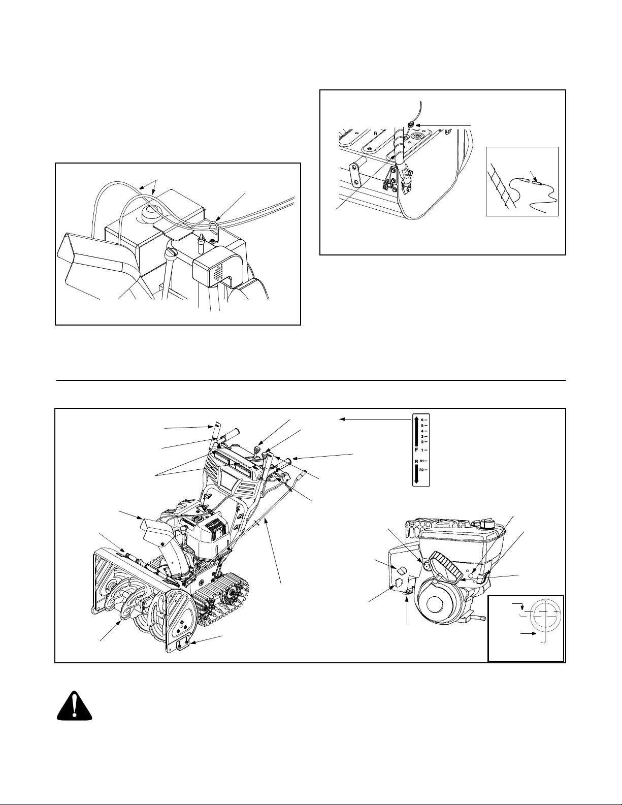
SECTION 3: KNOW YOUR SNOWTHROWER
Drive Control /
Auger Control Lock
Heated Handles
Switch†
Headlight†
Chute
Assembly
Clean-Out
Too l
Auger
Chute Directional
Control
Skid Shoe
Shift Lever
Chute Tilt
Control
Auger Drive Control
Track Steering
Control
† Optional
Figure 6
Heated Grip†
Primer
Choke
Safety
Ignition Key
Throttle
Control
Electric
Starter
Button
Switch
Box
Recoil
Starter
Handle
Closed
Open
Fuel Shut-Off Valve
*If Equipped
WARNING: Read, understand, and follow
all instructions and warnings on the machine
and in this manual before operating.
Drive Control / Auger Control Lock
The drive control is located on the right handle.
Squeeze the drive control to engage the wheel drive.
Release to stop. See Figure 6.
6
Page 7
The drive control also locks the auger control so you
can turn the chute directional control without
interrupting the snow throwing process. If the auger
control is engaged simultaneously with the drive
control, the operator can release the auger control (on
the left handle) and the augers will remain engaged.
Release both controls to stop the augers and track
drive.
IMPORTANT:
changing speeds.
Always release drive control before
Auger Drive Control
The auger drive control is located on
the left handle. Squeeze the control
grip to engage the augers. Release to
stop the snow throwing action. The
drive control must also be released in
order to stop auger. See Figure 6.
IMPORTANT:
to operating your snow thrower. Read and follow all
instructions carefully and perform all adjustments to
verify your snow thrower is operating safely and
properly.
Refer to Auger Control Test on page 10 prior
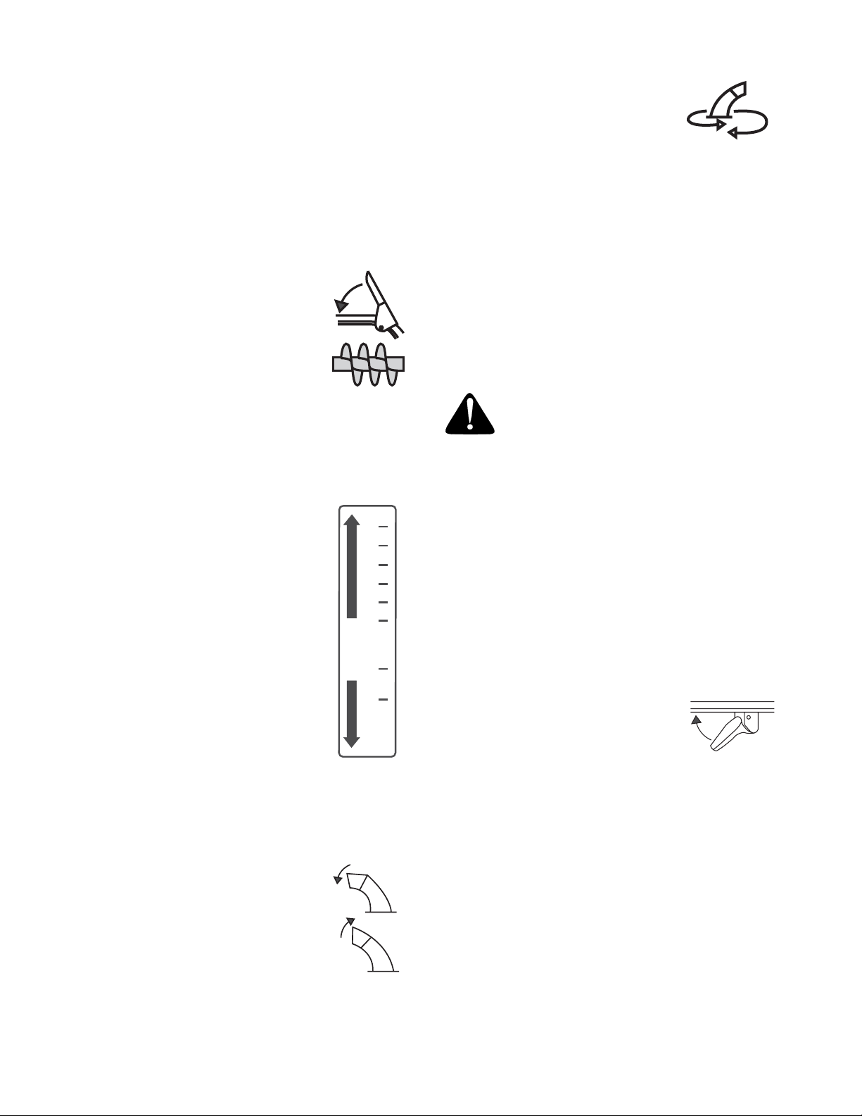
Shift Lever
F
R
6
5
4
3
2
1
R1
R2
The shift lever is located in the center of the handle panel and is used to
determine both ground speed and
direction of travel. It can be moved
into any of eight positions. See Figure 6.
IMPORTANT:
control before changing speeds.
Always release drive
Forward
Your snow thrower has six forward
(F) speeds, with position number
one (1) being the slowest speed,
and position number six (6) being
the fastest.
Reverse
Your snow thrower has two reverse (R) speeds, R1 is
the slower of the two.
Chute Tilt Control
The distance snow is thrown can be
changed by adjusting the angle of the
chute assembly. Move the chute tilt
control forward to decrease the
distance, toward the rear to increase.
Chute Crank
The chute crank is located on the left
side of the snow thrower. Use it to
change the direction in which snow is
thrown. Avoid targeting persons,
animals or cars and buildings.
CLOCKWISE TO
DISCHARGE LEFT
COUNTER CLOCKWISE
TO DISCHARGE RIGH
Skid Shoe
The space between the shave plate and the ground can
be adjusted by positioning the skid shoes. Refer to Skid
Shoe Adjustment on page 12.
Clean-Out Tool
The clean-out tool is designed to clear a clogged chute.
Refer to page 10 for instructions on how to properly use
it.
WARNING: Never use your hand to clear
a clogged chute. Shut off engine and remain
behind handles until all moving parts have
stopped before unclogging.
Heated Handles Switch (on some models)
This switch is located on the right side of the snow
thrower dash panel. To activate the heated handles,
toggle the switch to the right to generate heat within the
handle grips. Toggle the switch to the left to the OFF
position after using the snow thrower. See Figure 6.
NOTE: The heated handles grips are a compliment to,
not a substitute for, proper cold weather outerwear for
the operator’s hands. It is recommended that the snow
thrower operator wear gloves/mittens to avoid
extremities of winter while operating this equipment.
Track Steering Controls
The left and right track steering
controls are located on the underside
of the handles and they are used to
assist in steering the snow thrower. Squeeze the right
track control when turning right, squeeze the left control
when turning left. Operate your snow thrower in open
areas until you become familiar with these controls.
See Figure 6.
NOTE: It is easier to maneuver a non-running snow
thrower with both track steering controls held in
simultaneously.
Throttle Control
The throttle control is located on the engine. It regulates
the speed of the engine and will shut off the engine
when pushed down completely. See Figure 6.
T
7
Page 8

Fuel Shut-Off Valve (Optional Equipment)
On models so equipped, the fuel shut-off valve, located
under fuel tank, controls fuel-flow from the fuel tank to
the engine. See Figure 6.
for easy transport. May also be used on many gravel
driveways to clear snow while leaving gravel
undisturbed.
Normal Snow: Allows the tracks to be suspended
independently for continuous ground contact.
Safety Ignition Key
The safety ignition key must be fully inserted and
snapped in place before the unit will start. Remove the
ignition key to prevent unauthorized use of equipment.
See Figure 6.
IMPORTANT:
Do NOT attempt to turn the key.
Packed
Snow
Headlight
The headlight is on whenever the engine is running.
Track Lock Lever
The track lock lever is located on the right side of the
snow thrower and is used to select the position of the
auger housing and the method of track operation. Move
the lever to the right, then forward or backward to one of
the three positions. See Figure 7.
Transport: Keeps the front end of the snow thrower up
Packed Snow: Locks the front end of the snow thrower
down to the ground for hard-packed or icy snow
conditions.
Normal
Snow
SECTION 4: OPERATING YOUR SNOW THROWER
Track Lock
Lever
Transport
Figure 7
Before Starting
WARNING: Read, understand, and follow
all instructions and warnings on the machine
and in this manual before operating.
Gas And Oil Fill-up
Service the engine with gasoline and oil as
instructed in the separate engine manual packed with
your snow thrower. Read instructions carefully.
WARNING: Use extreme care when
handling gasoline. Gasoline is extremely
flammable and the vapors are explosive.
Never fuel machine indoors or while the
engine is hot or running. Extinguish
cigarettes, cigars, pipes and other sources of
ignition.
To Start Engine
NOTE: If unit shows any sign of motion (drive or
augers) with the clutch grips disengaged, shut engine
off immediately. Readjust as instructed in the Final
Adjustments in the Assembly Section.
• Attach spark plug wire to spark plug. Make certain
the metal loop on end of the spark plug wire (inside
the boot) is fastened securely over the metal tip on
the spark plug.
• Make certain the fuel shut-off valve, if so equipped,
is in the OPEN (vertical) position.
• Make certain the auger and drive controls are in the
disengaged (up) position.
• Move throttle control up to FAST position. Insert
ignition key into slot and snap in place. See Figure
6. Be certain it snaps into place. Do not turn key.
NOTE: Engine will not start unless ignition key is
inserted into ignition slot in carburetor cover.
Electric Starter (optional)
• Determine that your house wiring is a three-wire
grounded system. Ask a licensed electrician if you
are not certain.
• If your house wiring system is not a three-wire
grounded system, do not use this electric starter
under any conditions.
8
Page 9

WARNING: The electric starter is
equipped with a grounded three-wire power
cord and plug and is designed to operate on
120 volt AC household current. It must be
used with a properly grounded three-prong
receptacle at all times to avoid the possibility
of electric shock. Follow all instructions
carefully prior to operating the electric starter.
• If your home electrical system is grounded, but a
three-hole receptacle is not available, one should
be installed by a licensed electrician before using
the electric starter.
• If you have a grounded three-prong receptacle,
proceed as follows:
• Connect power cord to switch box on engine. Plug
the other end of power cord into a three-prong, 120volt, grounded, AC receptacle.
• Rotate choke knob to ON or FULL choke position
(cold engine start). If engine is warm, place choke
in OFF position instead of FULL.
• Push primer button three times for cold engine
start, making sure to cover vent hole in primer
button when pushing. DO NOT use primer to restart
a warm engine after a short shutdown.
• Push starter button to start engine.
• When engine starts, release starter button, and
move choke gradually to OFF. If engine falters,
move choke immediately to ON or FULL and then
gradually to OFF.
• When disconnecting the power cord, always unplug
from the three-prong receptacle first and then from
the snow thrower.
Recoil Starter
• Rotate choke knob to ON or FULL choke position
(cold engine start). If engine is warm, place choke
in OFF position instead of ON or FULL.
• Push primer button three times for cold engine
start. DO NOT use primer to restart a warm engine
after a short shutdown.
NOTE: Always cover vent hole in primer button when
pushing. Additional priming may be necessary for first
start if temperature is below 15°F (-9°C).
To Stop Engine
• Run engine for a few minutes before stopping to
help dry off any moisture on the engine.
• To help prevent possible freeze-up of starter,
proceed as follows:
Electric Starter:
• Connect power cord to switch box on engine, then
to 120 volt AC receptacle. With the engine running,
push starter button and spin the starter for several
seconds. The unusual sound made by spinning the
starter will not harm engine or starter. Disconnect
the power cord from receptacle first, and then from
switch box.
Recoil Starter
• With engine running, pull starter rope with a rapid,
continuous full arm stroke three or four times.
Pulling the starter rope will produce a loud clattering
sound, which is not harmful to the engine or starter.
• Move throttle control to “stop” or “off” position.
• Remove ignition key (DO NOT turn key) to prevent
unauthorized use of equipment.
• Disconnect the spark plug wire from the spark plug
to prevent accidental starting while equipment is
unattended.
NOTE: Do not lose ignition key. Keep it in a safe place.
Engine will not start without ignition key.
• Wipe all snow and moisture from the carburetor
cover in the area of the control levers. Also, move
control levers back and forth several times.
To Engage Drive
• With the engine running near top speed, move shift
lever to one of the eight positions to set desired
speed and direction. Select speed appropriate for
the snow conditions that exist.
NOTE: Use slower speeds in higher snow and/or until
you are familiar with the snow thrower operation.
• Squeeze drive control against the right handle to
move the snow thrower; release it to stop.
IMPORTANT:
releasing the drive control. Doing so will cause
premature wear on the drive system’s friction wheel.
NEVER move the shift lever without first
• Grasp starter handle and pull rope out slowly, until
it pulls slightly harder. Let rope rewind slowly.
• Pull starter handle rapidly. Do not allow handle to
snap back. Allow it to rewind slowly while keeping a
firm hold on the starter handle.
• Repeat the previous steps until engine starts.
• As engine warms up, rotate choke knob slowly to
OFF position. If engine falters, return to FULL
choke, then slowly move to OFF position
To Engage Augers
• To engage augers and start snow throwing,
squeeze the auger control against the left handle.
• To disengage power to the augers, release both the
auger control and the drive control, if engaged.
NOTE: The drive control also locks the auger control so
you can turn the chute directional control without
interrupting the snow throwing process. If the auger
control is engaged simultaneously with the drive
control, the operator can release the auger control (on
the left handle) and the augers will remain engaged.
Release both controls to stop the augers and track
drive.
9
Page 10

Auger Control Test
IMPORTANT:
operating your snow thrower for the first time and at the
start of each winter season.
Check the adjustment of the
auger control as follows:
• When the auger control is
released and in the
disengaged “up” position,
the cable should have
very little slack. It should
NOT be tight.
Perform the following test before
WARNING: Do not over-tighten the cable.
Over-tightening may prevent the auger from
disengaging and compromise the safety of
the snow thrower.
• In a well-ventilated area, start the snow thrower
engine as instructed earlier in this section under the
heading “Starting Engine”. Make sure the throttle is
set in the FAST position.
• While standing in the operator’s position (behind
the snow thrower), engage the auger.
• Allow the auger to remain engaged for
approximately ten (10) seconds before releasing
the auger control. Repeat this several times.
• With the engine running in the FAST position and
the auger control in the disengaged “up” position,
walk to the front of the machine.
• Confirm that the auger has completely stopped
rotating and shows NO signs of motion.
IMPORTANT:
immediately return to the operator’s position and shut
off the engine. Wait for ALL moving parts to stop before
re-adjusting the auger control.
• To readjust the control cable,
loosen the hex jam nut on the
auger control cable “Z” fitting.
• Thread the ferrule without turning
the cable onto the “Z” fitting until
there is no slack in the cable. See
Figure 8. Do not overtighten the
cable. Hold the flats on the ferrule
with pliers and tighten the jam nut
against the ferrule.
• Rotate the coupling end of the cable
counterclockwise to provide more slack.
• Retighten the hex jam nut. See Figure 8.
• Repeat Auger Control Test to verify proper
adjustment has been achieved.
If the auger shows ANY signs of rotating,
Hex Jam Nut
Hex Jam Nut
Flats
“Z” Fitting
Ferrule
Cable
Figure 8
Clean-Out Tool
The chute clean-out tool is conveniently fastened to the
rear of the auger housing with a mounting clip. Never
use your hand to clean a clogged chute or chute
opening; use this clean-out tool instead.
• Release both the Auger Control and the
Auger Control Lock.
• Stop the engine by moving the throttle to the stop
position.
• Remove the clean-out tool from the mounting clip.
See Figure 6.
• Use the shovel-shaped end of the clean-out tool to
dislodge and scoop any snow and ice which has
formed in and near the chute assembly.
Drive/
WARNING: Never use your hands to clean
snow and ice from the chute assembly or
auger housing.
• Refasten the clean-out tool to the mounting clip on
the rear of the auger housing, reinsert the ignition
key and start the snow thrower’s engine.
• While standing in the operator’s position (behind
the snow thrower), engage the auger control for a
few seconds to clear any remaining snow and ice
from the chute before continuing to clear snow.
Drift Cutters (If Equipped)
Drift cutters should be used when operating the snow
thrower in heavy drift conditions.
On models so equipped, drift cutters are assembled to
the auger housing inverted. Remove the carriage bolts
by unthreading the hex nuts which secure them, and
reinstall the drift cutters in their proper position before
operating the snow thrower. See Figure 9.
If your unit is not equipped with drift cutters, contact
Customer Support as instructed on page 2 for
information regarding price and availability.
Snow Thrower ModelDrift Cutter Kit
All models OEM-390-679
10
Page 11
Operating Tips
NOTE: Allow the engine to warm up for a few minutes.
The engine will not develop full power until it reaches
operating temperature.
NOTE: The temperature of the muffler and
the surrounding areas may exceed 150°F
(65°C).
Drift
Cutter
Carriage Screws
& Hex Nuts
Figure 9
SECTION 5: MAKING ADJUSTMENTS
WARNING: NEVER attempt to make any
adjustments while the engine is running,
except where specified in the operator’s
manual.
Chute Assembly
The distance snow is thrown can be adjusted by
adjusting the angle of the chute assembly. Refer to
“Know Your Snowthrower” for instructions.
The remote chute control cables have been preadjusted at the factory. Move the remote chute lever on
the control panel back and forward to adjust angle of
the chute assembly.
• For the most efficient snow removal, remove snow
immediately after it falls.
• Discharge the snow downwind whenever possible.
• Slightly overlap each previous path.
• Set the skid shoes 1/4" below the shave plate for
normal usage. The skid shoes may be adjusted
upward (to lower the shave plate) for hard-packed
snow. Adjust downward (to raise the shave plate)
when using on gravel or crushed rock.
• Be certain to follow the precautions found in the “To
Stop Engine” section to prevent possible freeze-up.
• Clean the snow thrower thoroughly after each use.
• Move the shift lever back to the fast reverse
position then all the way forward again. There
should be no resistance in the shift lever, and the
tracks should keep turning.
• If you have resistance when moving the shift lever
or the tracks stop when they should not, loosen the
jam nut on the drive control cable and unthread the
cable one turn.
• If the tracks do not stop when you engage the drive
control, loosen the jam nut on the drive control
cable and thread the cable in one turn.
• Recheck the adjustment and repeat as necessary.
Tighten the jam nut to secure the cable when
correct adjustment is reached.
Auger Control
Refer to Auger Control Test in the Operating Section to
adjust the auger control.
Drive Control and Shift Lever
To check the adjustment of the drive control and shift
lever, proceed as follows:
• With the engine off, move the shift lever all the way
forward to the highest speed. With the drive control
lever released, push the snow thrower forward. The
unit should roll forward. Then engage the drive
control. The tracks should stop turning.
• Now release the drive control and push the unit
again.
WARNING: Drain the gasoline out of the
snow thrower’s tank, or place a piece of
plastic film under the gas cap to avoid
spillage BEFORE making the adjustment.
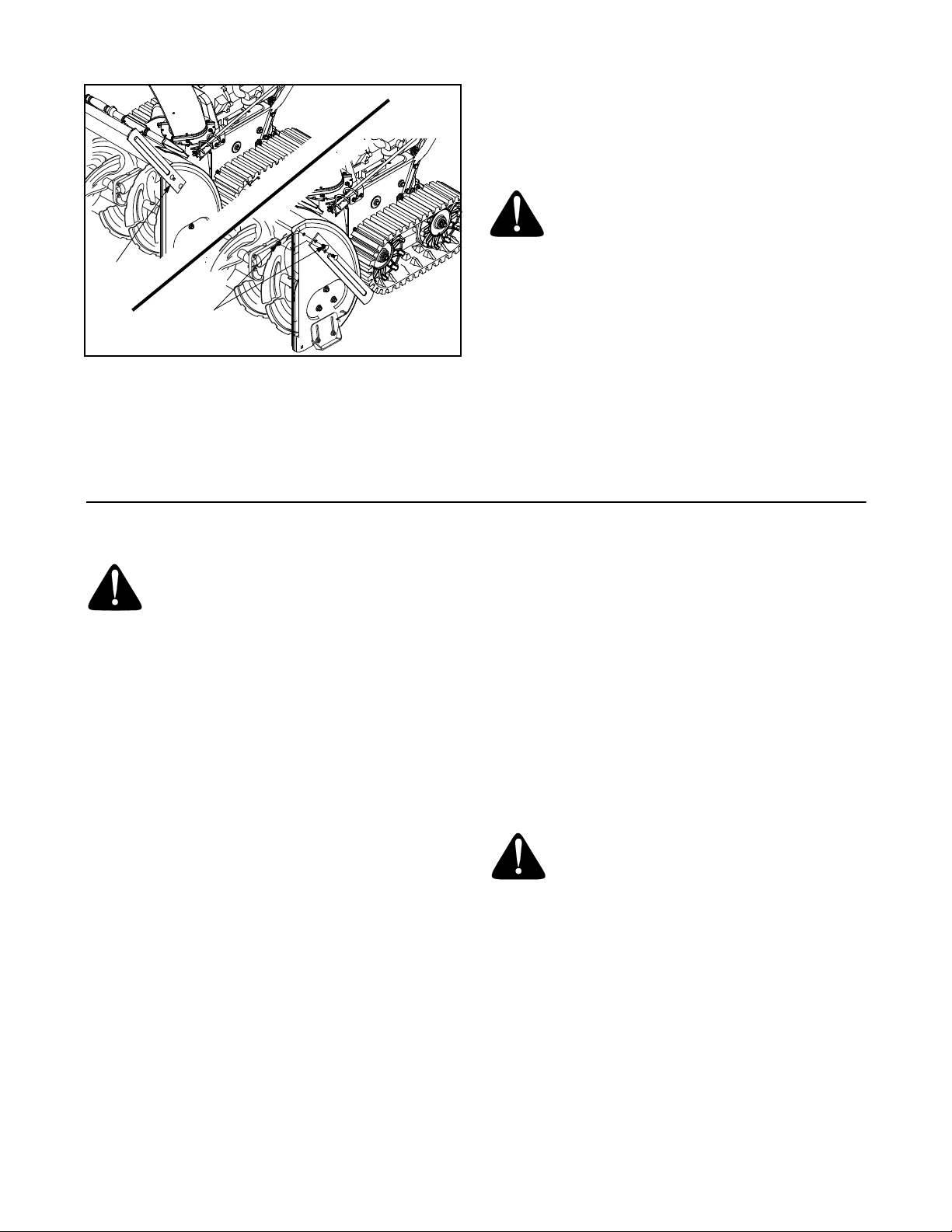
To test further for correct adjustment, if necessary,
proceed as follows:
• Tip the snow thrower forward, allowing it to rest on
the auger housing. See Figure 10.
• Remove the frame cover underneath the snow
thrower by removing the six self-tapping screws.
• With the drive control released, there must be
clearance between the friction wheel and the drive
plate in all positions of the shift lever. See Figure
11.
11
Page 12

Frame Cover
hole in the shift lever. See Figure 12.
• Insert ferrule from the left side of the snow thrower
into the upper hole.
• Reinstall the hairpin clip and the washer.
Shift Lever
Hairpin Clip
Auger
Housing
Figure 10
• With the traction control lever engaged, the friction
wheel must contact the drive plate. See Figure 11.
If adjustment is necessary:
• Loosen the jam nut on the traction cable and thread
the cable in or out as necessary.
• Retighten the jam nut to secure the cable when
correct adjustment is reached.
• Reassemble the frame cover.
Gear Shaft
Friction Wheel
Rubber
Drive
Cable
Pivot Rod
Drive
Plate
Figure 11
NOTE: If you placed plastic film under the gas cap, be
certain to remove it before operating the snow thrower.
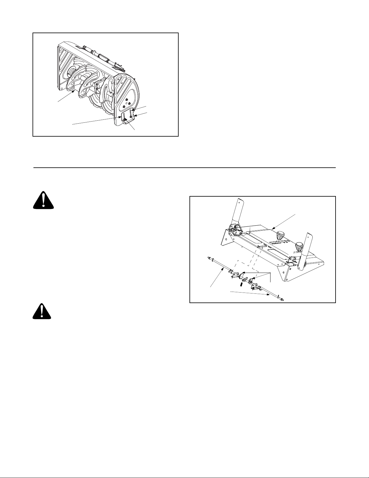
Shift Rod Adjustment
• Remove the hairpin clip and flat washer from the
shift handle under the handle panel. See Figure 12.
• Place shift lever in sixth (6) position or fastest
forward speed.
• Push shift arm assembly down as far as it will go.
• Rotate the ferrule up or down on the shift rod as
necessary until the ferrule lines up with the upper
Flat
Washer
Shift Rod
Connector
Lower Shift Rod
Shift Arm
Ferrule
Upper Shift Rod
Hairpin Clip
Figure 12
IMPORTANT:
Make certain to check for correct
adjustment of the shift rod as instructed under “Drive
Control and Shift Lever” on page 11, before operating
the snow thrower.
Skid Shoe
The space between the shave plate and the ground can
be adjusted by raising or lowering the skid shoes.
For close snow removal, as when using on a smooth
concrete or asphalt driveway, place the skid shoes in
the low position. Use the middle or high position when
the area to be cleared is uneven. When operating on
gravel, always put skid shoes in the high position.
See Figure 13.
Adjust skid shoes as follows:
• Loosen, but do not remove, the three hex nuts
which fasten the skid shoe to the auger housing.
• Raise or lower the skid shoe to desired position.
• Retighten the hex nuts loosened earlier.
• Repeat on the other side of the snow thrower.
NOTE: Make certain the bottom surface of skid shoe is
flat against the ground to avoid uneven wear.
12
Page 13
Carburetor
• Minor carburetor adjustment may be required to
compensate for differences in fuel, temperature,
altitude and load.
• Refer to the separate engine manual, packed with
your unit, for carburetor adjustment information.
Shave Plate
Skid
Shoe
Figure 13
High
Low
Flange Locknut
SECTION 6: MAINTAINING YOUR SNOW THROWER
WARNING: Before lubricating, repairing, or
inspecting, disengage all clutch levers and
stop engine. Wait until all moving parts have
come to a complete stop. Disconnect spark
plug wire and ground it against the engine to
prevent unintended starting. Always wear
safety glasses during operation or while
performing any adjustments or repairs.
Lubrication
Engine
Refer to the separate engine manual packed with the
snowthrower for detailed instructions regarding all
engine-related maintenance.
Control Rods
Handle Panel
Lube Cams Here
WARNING: If any adjustments need to be
made to the engine while the engine is
running (e.g. carburetor), keep clear of all
moving parts. Be careful of muffler, engine
and other surrounding heated surfaces.
Drive / Auger Control Lock
The cams on the ends of the control rods which
interlock the drive and auger controls must be
lubricated at least once a season or every 25 hours of
operation. The cams can be accessed beneath the
handle panel. Use a multi-purpose automotive grease.
See Figure 14.
Figure 14
Gear Case
The gear case is lubricated with grease at the factory
and it does not require checking. If disassembled for
any reason, lubricate with 2 ounces of Shell Alvania
grease EPR00, part number 737-0168. Before
reassembling, remove old sealant and apply new
sealant.
13
Page 14

Shear Pin
Plastic
Bearing
To check the level of grease in the gear case, remove
the vent plug. If your unit is equipped with a grease
fitting, you may, if necessary, add grease using a
grease gun and the grease fitting on the side of the gear
case.
IMPORTANT:
damage to the seals could result. Be sure the vent plug
is free of grease in order to relieve pressure.
Do not overfill the gear case, since
Vent Plug
Bearings
Figure 15
Auger Shaft
• At least once a season, remove the shear pins from
the auger shaft and spray lubricant inside the shaft.
See Figure 15.
• On certain models, grease fittings can be found at
either end of the auger shaft. Lubricate with a
grease gun once a season.
Auger Bearings
Every season lubricate the auger bearings and the
bearings on the side of the frame with light oil. See
Figure 15.
Drive and Shifting Mechanism
Lubricate at least once a season or after every 25 hours
of operation. Remove the rear cover, lubricate any
chains, sprockets, gears, bearings, shafts, and shifting
mechanism at least once a season. Use engine oil or a
spray lubricant. Avoid getting oil on the friction
wheel rubber and aluminum drive plate. Refer to
Figure 11.
There is a grease fitting on the top of the axle shaft
which drives the rear track drive wheels on both sides
of the unit. Grease these fittings every 25 hours or once
a season.
Gear Shaft
Lubricate the gear shaft with 6-n-1 grease at least once
a season or after every 25 hours of operation (available
at automotive stores, or order part number 737-0170).
Refer to Figure 11.
IMPORTANT:
friction wheel and aluminum drive plate.
Keep all grease and oil off of the rubber
Chute Directional Control
The worm gear on the chute directional control should
be greased with multipurpose automotive grease.
SECTION 7: SERVICING YOUR SNOW THROWER
WARNING: Before servicing, repairing, or
inspecting, disengage all controls and stop
engine. Wait until all moving parts have come
to a complete stop. Disconnect spark plug
wire and ground it against the engine to
prevent unintended starting. Always wear
safety glasses during operation or while
performing any adjustments or repairs.
Augers
• The augers are secured to the spiral shaft with
shear pins and bow tie cotter pins. If you hit a hard
foreign object or ice jam, the snow thrower is
designed so that the pins may shear. Refer to
Figure 17.
• If the augers will not turn, check to see if the pins
have sheared. Replacement shear pins and cotter
pins have been provided with the snow thrower.
14
When replacing pins, spray an oil lubricant into
shaft before inserting new pins.
IMPORTANT:
standard pins. Any damage to the auger gearbox or
other components as a result of doing so will NOT be
covered by your snow thrower’s warranty.
Shave Plate and Skid Shoes
• The shave plate and skid shoes on the bottom of
the snow thrower are subject to wear. They should
be checked periodically and replaced when
necessary.
NEVER replace the auger shear pins with
Page 15
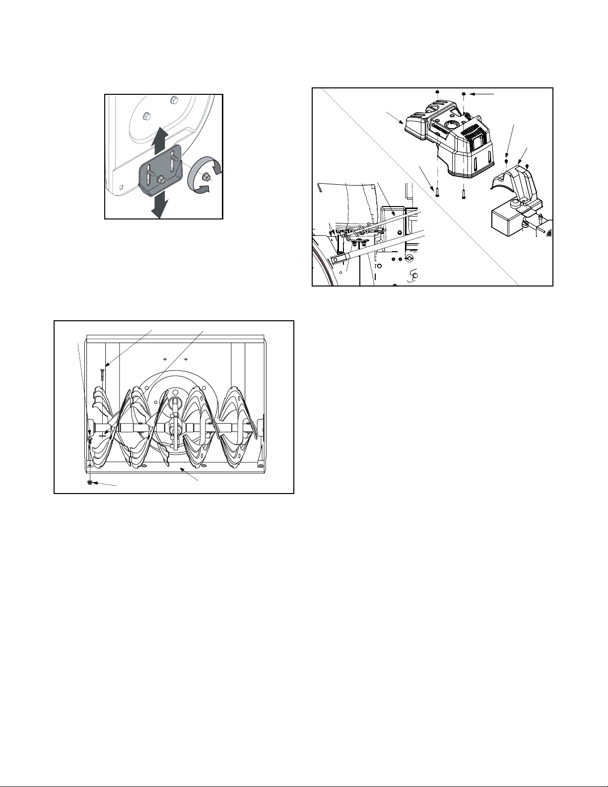
• Remove the carriage bolts and flange lock nuts
which attach the two skid shoes to the snow thrower
on two sides. See Figure 16.
Figure 16
• Reassemble new skid shoes with the hardware
removed earlier. Make certain the skid shoes are
adjusted to be level.
• To remove the shave plate, remove the carriage
bolts and flange lock nuts which attach the shave
plate to the snow thrower housing. See Figure 17.
Carriage
Bolt
Flange Lock
Nut
Shear Pin
Bow Tie Cotter Pin
Shave
Plate
Figure 17
• Reassemble the new shave plate, with heads of
carriage bolts to the inside of the housing. Tighten
securely.
• Disconnect the chute directional control at the
discharge chute end by removing the hairpin clip
and the flat washer. See Figure 18A.
A
Hairpin
Clip, Flat
Washer
Engine
Shroud
Chute
Directional
Control
Hex
Bolt
Lock Nut
Self-Tapping
Screw
Belt
Cover
B
Figure 18
• Remove the engine shroud by removing the lock
nuts and bolts securing it. See Figure 18B.
• Remove the plastic belt cover at the front of the
engine by removing the two self-tapping screws.
See Figure 18B.
• Drain the gasoline from the snow thrower, or place
a piece of plastic film under the gas cap.
• Tip the snow thrower up and forward so that it rests
on its auger housing. Refer to Figure 10.
• Remove the six self-tapping screws from the frame
cover underneath the snow thrower.
• Roll the front and rear auger belts off the engine
pulley. See Figure 19.
• Unhook the idler spring from the hex bolt on the
auger housing. See Figure 20.
• Back out the stop bolt until the support bracket
rests on the auger pulley. See Figure 21.
NOTE: Loosening the six nuts that connect the frame to
the auger housing may aid in belt removal.
Belt Removal And Replacement
Auger Belts
NOTE: It is necessary to remove both belts in order to
change either one. If changing just one belt, be certain
to check the condition of the other belt.
15
Page 16

Auger
Pulley
Idler
Pulley
Drive
Pulley
Drive
Belt
Idler
Pulley
• Slip the belt between the friction wheel and drive
disc. Remove and replace the belt. Reassemble
following the instructions in reverse order.
NOTE: The support bracket must rest on the stop bolt
after the new belt has been assembled. See Figure 21.
Friction
Wheel
Drive Plate
Auger
Belts
Frame
Figure 19
• Lift the auger belt from the auger pulley, and slip
belt between the support bracket and the auger
pulley. Repeat this step for the front auger belt. See
Figure 20.
• Replace both auger drive belts by following
instructions in reverse order.
NOTE: If you placed plastic film under the gas cap, be
certain to remove it before operating the snow thrower.
Support
Bracket
Auger
Pulley
Rear
Auger
Belt
Front
Auger Belt
Idler
Spring
Frame
Support
Bracket
Spring
Auger
Housing
Figure 20
Drive Belt
• Follow the first six steps of the instructions for
servicing the auger belts.
• Pull the idler pulley up and lift the belt off the engine
pulley and friction wheel disc. See Figure 19.
• Back out the stop bolt until the support bracket
rests on the auger pulley. See Figure 21.
Stop Bolt
Support Bracket
Auger Pulley
Figure 21
Replacing Friction Wheel Rubber
The rubber on the friction wheel is subject to wear and
should be checked after 25 hours of operation, and
periodically thereafter. Replace the friction wheel
rubber if any signs of wear or cracking are found.
• Drain the gasoline from the snow thrower.
• Tip the snow thrower up and forward, so that it rests
on the housing. Refer to Figure 10.
• Remove six self-tapping screws from the frame
cover underneath the snow thrower.
• Using a 7/8" wrench to hold the shaft, loosen, but
do not completely remove, the hex bolt and cupped
washer on the left end of gear shaft. See Figure 22.
• Lightly tap the hex nut to dislodge the ball bearing
from the right side of frame before removing the hex
nut and bell washer from left end of shaft.
• Move the gear shaft to the right and slide the friction
wheel assembly from the shaft. See Figure 23A.
• Remove the four screws from the friction wheel
assembly. See Figure 23B.
• Remove the friction wheel rubber from between the
friction wheel plates.
• Reassemble new friction wheel rubber to the
friction wheel plates and hub, tightening the four
screws in rotation and with equal force.
16
Page 17

A
Spacer
Support
Bracket
Track
Hex Bolt and
Cupped Washer
Figure 22
Sprocket
Shift Rod
Assembly
Friction Wheel
Assembly
Shaft
Pin
• Position the friction wheel assembly up onto the pin
of the shift rod assembly, and slide the shaft
through the assembly. Reassemble in reverse
order.
Engine
Refer to the separate engine manual packed with your
unit.
Off-Season Storage
WARNING: Never store the machine or
fuel container indoors where there is an open
flame, spark, or pilot light such as on water
heater, furnace, clothes dryer, or other gas
appliance.
If unit is to be stored over 30 days, prepare for storage
as instructed in the separate engine manual packed
with your snow thrower.
• Clean snow thrower thoroughly.
• Lubricate as instructed in the Maintaining Your
Snow Thrower section of this manual.
• Store the snow thrower in a clean, dry area.
NOTE: When storing any type of power equipment in a
poorly ventilated or metal storage shed, care should be
taken to rustproof the equipment, especially springs,
cables and all moving parts.
Screws
B
Friction Wheel
Plates
Friction Wheel Rubber
Hub
Figure 23
17
Page 18

SECTION 8: TROUBLESHOOTING
Problem Cause Remedy
Engine fails to start. 1. Fuel tank empty, or stale fuel.
2. Blocked fuel line.
3. Choke not in ON position
4. Faulty spark plug.
5. Safety key not in ignition switch on engine.
6. Spark plug wire disconnected.
7. Primer button not being used properly.
Engine runs erratic. 1. Unit running on CHOKE.
2. Blocked fuel line or stale fuel.
3. Water or dirt in fuel system.
4. Carburetor out of adjustment.
Loss of power. 1. Spark plug wire loose.
2. Gas cap vent hole plugged.
3. Exhaust port plugged.
Engine overheats. 1. Carburetor not adjusted properly. 1. Refer to the engine manual or have the
Excessive vibration. 1. Loose parts or damaged auger. 1. Stop engine immediately and disconnect
Unit fails
to propel itself.
Unit fails
to discharge snow.
1. Traction control cable in need of adjustment.
2. Drive belt loose or damaged.
1. Discharge chute clogged.
2. Foreign object lodged in auger.
3. Auger control cable in need of adjustment.
4. Auger belt loose or damaged.
5. Shear pin(s) sheared.
1. Fill tank with fresh gasoline.
2. Clean the fuel line.
3. Move switch to ON position
4. Clean, adjust gap or replace.
5. Insert the key fully into the switch.
6. Connect spark plug wire.
7. Refer to the engine manual.
1. Move choke lever to OFF position.
2. Clean fuel line and fill tank with clean, fresh
gasoline.
3. Drain fuel tank and carburetor. Refill with
fresh fuel.
4. Refer to the engine manual.
1. Connect and tighten spark plug wire.
2. Remove ice and snow from gas cap. Be
certain vent hole is clear.
3. Refer to the engine manual.
carburetor adjusted by an authorized
engine service dealer.
spark plug wire. Tighten all bolts and nuts. If
vibration continues, have unit serviced by
an authorized service dealer.
1. Adjust traction control cable. Refer to
Adjustments.
2. Replace drive belt.
1. Stop engine immediately and disconnect
spark plug wire. Clean discharge chute and
inside of auger housing.
2. Stop engine immediately and disconnect
spark plug wire. Remove object from auger.
3. Refer to Auger Control Test, Operating Your
Snowthrower Section.
4. Refer to Maintenance Section
5. Replace shear pin(s).
NOTE: For repairs beyond minor adjustments listed above, contact the local dealer.
18
Page 19

SECTION 9: TWO YEAR SUPREME WARRANTY:
For two years from date of retail purchase within Canada, MTD PRODUCTS LIMITED will, at its
option, repair or replace, for the original purchaser, free of charge, any part or parts found to be
defective in material or workmanship. This warranty covers units which have been operated and
maintained in accordance with the owner’s instructions furnished with the unit, and which have
not been subject to misuse, abuse, commercial use, neglect, accident improper maintenance or
alteration. Normal wear parts or components thereof are subject to special terms as noted
below in the NO FAULT Ninety Day Consumer Warranty clause.
The engine, starter motor or component parts thereof carry separate warranties from their
manufacturers. Please refer to the applicable manufacturer’s warranty policy for these items.
NO FAULT Ninety Day Consumer Warranty on Normal Wear Parts: All normal wear part
failures will be covered on this product for a period of 90 days regardless of cause. After 90 days
but within the two year warranty period, normal wear part failures will be covered if caused by
defects in material or workmanship of other component parts. Normal wear parts are defined as
batteries, belts, blades, blade adaptors, grass bags, rider deck wheels, seats, tires and clutch
parts (friction wheels).
Full Ninety Day Warranty on Battery: For ninety (90) days from the date of retail purchase, if
any battery included with this unit proves defective in material or workmanship and our testing
determines the battery will not hold a charge, MTD PRODUCTS LIMITED will replace the battery
at no charge to the original purchaser.
Additional Limited Thirty Day Warranty on Battery: After ninety (90) days but within one
hundred twenty (120) days from the date of purchase, MTD PRODUCTS LIMITED will replace
the defective battery, for the original purchaser, for a cost of one -half (½) of the current retail
price of the battery in effect at the date of return.
How to Obtain Service: Warranty service is available, with proof of purchase, through your
local MTD Authorized Service Dealer. If you do not know the dealer in your area, please write to
the Service Department of MTD PRODUCTS LIMITED, P.O. BOX 1386, KITCHENER,
ONTARIO N2G 4J1. The return of a complete unit will not be accepted by the factory unless
prior written permission has been extended by MTD PRODUCTS LIMITED.
Other Warranties: All other warranties, express or implied, including any implied warranty of
merchantability is limited in its duration to that set forth in this express limited warranty. The
provisions as set forth in this warranty provide the sole and exclusive remedy of MTD
PRODUCTS LIMITED obligations arising from the sale of its products. MTD PRODUCTS
LIMITED will not be liable for incidental or consequential loss or damage.
19
Page 20

1
11
19
5
6
17
7
22
11
27
21
8
13
25
4
9
3
24
20
14
26
11
19
30
29
32
34
38
39
40
41
42
9
11
45
45
46
47
48
49
50
51
52
53
54
54
55
56
57
58
59
60
40
61
62
63
64
65
9
67
68
69
9
70
71
72
53
40
16
74
75
76
77
9
64
81
68
79
43
78
28
23
10
75
75
16
15
12
75
66
70
44
2
73
18
11
37
33
80
31
35
84
36
80
83
82
8
5
87
17
SEC TION 10: PARTS LISTS/LISTE DE PIÈCES DÉTACHÉES
20
Page 21

REF PAR T
NO. NO.
N° DE N° DE
RÉF PIÈCE DE SCRIP TION DE SCRIP TION
1 684-0008A Shift Arm As sem bly Bras de commande
2 747-0737 Up per Chute Crank Manivelle de la bouche d’évacuation supérieur
3 710-0449 Car riage Bolt 5/16-18 x 2.25 Boulon ordi naire 5/16-18 x 2,25
4 710-0458 Car riage Bolt 5/16-18 X 1.75" Lg. Boulon à col let carré 5/16-18 X 1.75 po de lg
5 710-0643 Hex Screw 5/16-18 X 1.00 Spe cial Vis à tête hexagonale 5/16-18 X 1.00 Spéciale
6 710-0788 Hex Bolt 1/4-20 x 1.00 Vis à tête hex 1/4-20 x 1,00
7 710-1880 Hex Bolt 5/16-18 x 0.75 Boulon hex. 5/16-18 x 0,75
8 711-0677 Ad just ment Fer rule Virole de réglage
9 712-04063 Flange Locknut 5/16-18 Gr. F, Ny lon Contre-écrou à embase 5/16-18 Qual. F, ny lon
10 710-0703 Car riage Bolt 1/4-10 x .75 Boulon ordi naire 1/4-20 x 0,75
11 714-0104 Int. Cot ter Pin .072 x 1.13" Lg. Goupille fendue int. 0,072 x 1,13 po de lg.
12 720-0201A Knob 1.0 x 3.2 Bou ton 1,0 x 3,20
13 725-1757 Heated Grip Poignée chauffée
14 720-0284 Han dle Knob As sem bly Bou ton
15 726-0100 Push Nut 3/8" Rod Écrou pour tige de 3/8 po
16 710-0597 Hex Screw 1/4-20 x 1.00 Vis à tête hexagonale 1/4-20 x 1,00
17 736-0119 L-Wash 5/16 ID Rondelle frein 5/16 DI
18 736-0185 Flat Washer .406" I.D. x .75" O.D. Rondelle plate 0,406 DI x 0,75 DE
19 736-0275 Flat Washer .34 ID x .688 OD x .065 Rondelle plate 0,34 DI x 0,688 DE x 0,065
20 736-0451 Sad dle Wash. .320 ID x .937 OD Rondelle selle 0,320 DI x 0,937 DE
21 747-0620A Up per Shift Rod Tige de commande supérieur
22 747-0621 Lower Shift Rod Tige de commande inférieur
23 629-04007 Wire Har ness (Ht. grips & dual lights) Faisceau du fils
24 749-0951 Lower Han dle Guidon inférieur
25 749-0952A RH Up per Han dle Guidon supérieur - droite
26 749-0953A LH Up per Han dle Guidon supérieur - gauche
27 750-0963 Con nec tor - Shift Rod Raccord - tige de changement de la vitesse
28 710-0837 Oval HD C-Sunk Scr #10 x 5/8 Vis à tête goutte de suif n° 10 x 5/8
29 684-0036A En gage ment Han dle RH Red Poignée d’entraînement CD rouge
30 684-0037B En gage ment Han dle LH Red Poignée d’entraînement CG rouge
31 710-1003 Hex Wash B-Tapp Scr #10 x .62" Lg. Vis taraudée n°. 10 x 0,62 po de lg.
32 712-0271 Sems Hex Nut 1/4-20 Écrou Sems hex. 1/4-20
33 712-0693 Hex Nut Écrou à six pans
34 720-0232 Ball Knob Bou ton
35 725-1759 Halo gen lamp #886, 12 V, 50 watt Am poule à iode n°. 886, 12 V, 50 watt
36 725-1672 Lamp Hous ing Phare-carter
37 731-04068 Han dle Panel Panneau
38 684-0102 Han dle Panel Ass’y w/tilt Panneau
39 710-0459A Hex Scr 3/8-24 x 1.50 Vis à tête hexagonale 3/8-24 x 1,50
40 710-0599 Hex Wash S-Tapp Scr 1/4-20 x .50 Vis autotaraudeuse à rondelle hex. 1/4-20 x 0,50
41 711-0653 Clevis Pin .31 Dia. x 1.0" Lg. Axe d’attelage 0,31 dia. x 1,0 po de lg.
42 712-0116 Hex Nut 3/8-24 Écrou hex ag o nal 3/8-24
43 712-3010 Hex Nut 5/16-18 hd. (Gr. 5) Écrou hex ag o nal 5/16-18 Qual. 5
44 714-0145 Hair pin Cot ter Goupille fendue
45 714-0507 Cot ter Pin 3/32 x .75 Goupille fendue 3/32 x 0,75
46 732-0145 Com pres sion Spring .62 OD x 6.12" Lg. Ressort de com pres sion 0,62 DE x 6,12 po de lg.
47 732-0193 Com pres sion Spring .38 ID x .88 Lg Ressort de com pres sion 0,38 DI x 0,88 po de lg.
48 732-0746 Tor sion Spring Ressort de tor sion
49 735-0199A Rub ber Bumper Pare - chocs en caou tchouc
50 736-0105 Cupped Washer .375 ID x .870 ODx .063 Rondelle creuse 0,375 DI x 0,875 DE x 0,063
51 736-0509 Washer (spe cial) Rondelle - spéciale
52 746-0778 Z Fit ting Extrémité en «Z»
53 747-0877 Cam Rod Tige de came
54 748-0362 Cam Han dle Lock Came
55 748-0363 Cam Lock Pawl Cliquet
56 784-5619A Shift Le ver Lev ier de changement de la vitesses
57 784-5679 LH Han dle Sup port Brkt. Sup port de guidon-gauche
58 784-5680 RH Han dle Sup port Brkt. Sup port de guidon-droit
59 784-5681 LH Sup port Brkt. Sup port -gauche
60 784-5682 RH Sup port Brkt. Suppport -droit
61 710-0805 Hex Bolt 5/16-18 x 1,50" Lg. Gr. 5 Boulon hex. 5/16-18 x 1,50 po de lg Qual. 5
62 746-0901 Chute Con trol Ca ble w/clip Câble de la commande avec attache
21
Con tin ued on next page/Suite à la page prochaîne
Page 22

REF PAR T
NO. NO.
N° DE N° DE
RÉF PIÈCE DE SCRIP TION DE SCRIP TION
63 746-0896 Chute Con trol Ca ble Câble de la commande de la bouche d’évacuation
64 731-1313C Ca ble Guide Guide de la câble
65 784-5604 Chute Tilt Han dle Poignée de la bouche d’évacuation
66 705-5266 Up per Chute Crank Sup port Sup port de la manivelle de la goulotte
supérieure
67 736-0506A Con tour Washer Rondelle
68 710-0895 Hex Tapp Scr 1/4 x .75" Lg. Vis taraudée à tête hex de 1/4 x 0,75 po de lg
69 731-1379D Chute Adapter Adaptateur
70 741-0475 Plas tic Bush ing .380 ID Manchon en plastique de 0,38 po de D.I.
71 784-5647 Chute Crank Brkt. Sup port du bras de goulotte d’éjection
72 710-0451 Car riage Bolt 5/16-18 x .75 Boulon ordi naire 5/16-18 x 0,75
73 684-0053B Lower Chute Crank As sem bly Manivelle de la goulotte inférieure
74 731-0851A Chute Flange Keeper Guide de la goulotte
75 712-04064 Hex L-Flanged Nut 1/4-20 Gr. F Ny lon Contre-écrou à embase 1/4-20 Qual. F ny lon
76 731-1300C Lower Chute Partie inférieur de la bouche d’évacuation
77 731-04427A Up per Chute Goulotte supérieur
78 784-5594 Ca ble Bracket Chute Tilt Sup port de câble
79 710-04071 Car riage Screw 5/16-18 x 1.0 Vis ordi naire 5/16-18 x 1,0
80 716-0398 Lock Ring - Tog gle Switch Bague - commutateur à culbuteur
81 710-0262 Car riage Bolt 5/16-18 x 1.50 Gr. 2 Boulon ordi naire 5/16-18 x 1,50 Qual. 2
82 725-1756 Tog gle Switch - Sin gle Throw Commutateur à culbuteur
83 736-0226 Flat Washer .469 ID x .88 OD x .063 Rondelle plate 0,469 DI x 0,88 DE x 0,063
84 747-1136 Head light Re tainer Attache
87 629-0059 Halo gen Light Wire Har ness Faisceau de fil pour phare à iode
31A-701
5.10.05
22
Page 23

notes . . .
23
Page 24

10
43
47
44
38
46
19
32
45
17
9
20
31
36
49
23
18
48
50
25
16
33
34
35
15
28
26
22
27
21
12
14
11
16
5
6
3
7
16
8
4
2
28
13
16
30
37
52
1
41
40
39
24
29
42
16
16
34
24
Page 25

REF PAR T
NO. NO.
N° DE N° DE
RÉF PIÈCE DE SCRIP TION DE SCRIP TION
1 714-04040 Bow-Tie Cot ter Pin Goupille fendue
2 756-0178 Flat Idler Pul ley Poulie de tendeur plate
3 784-5632B Au ger Idler Bracket Sup port du tendeur
4 710-0347 Hex Screw 3/8-16 x 1.75 Vis à tête hex 3/8-16 x 1,75
5 738-0281 Shoul der Scr .625 Dia. x .170 Vis à épaulement dia. 0,625 x 0,170
6 736-0174 Wave Washer .660 ID x .88 OD x .010 Rondelle ondulée 0,660 DI x 0,88 DE x 0,010
7 732-0611 Ex ten sion Spring Ressort d’extension
8 712-3068 Hex Patch L-Nut 5/16-18 Écrou de blocage à six pans 5/16 - fil. 18
9 710-0642 Thd Form ing Scr. 1/4-20 x .75 Lg. Vis taraudée 1/4-20 x 0,75 lg.
10 711-04282 Au ger Axle (30") Arbre des tarières (30 po)
11 05931A Bear ing Plate Plaque de roulement
12 741-0309 Self-align ing bear ing Roulement auto-aligneur
13 710-0451 Car riage Bolt 5/16-18 x .75 Boulon ordi naire 5/16-18 x 0,75
14 705-5226 Chute Re in force ment Renfort de la bouche d’évacuation
15 684-04137A Au ger Hous ing Ass’y 30" Logement des tarières
16 712-04063 Flange Locknut 5/16-18 Gr. F, Ny lon Contre-écrou à embase 5/16-18 Qual. F, ny lon
17 714-0161 Wood ruff Key 3/16 x 5/8 HT Clavette Wood ruff 3/16 x 5/8
18 715-04021 Dowel Pin Goujon cheville
19 717-0528A Worm Gear Vis sans fin
20 717-0526 Im pel ler Shaft Arbre
21 731-2635 Mount ing Bracket Sup port de mon tage
22 731-2643 Chute Clean-Out Tool Outil de dégagement de la goulotte
23 718-04071 Thrust Col lar Bague de butée
24 790-00138A Bear ing Hous ing (w/Grease fit ting hole) Carter de la roulement (trou-raccord de graisse)
25 721-0325 Plug Bouchon
26 710-0726 Hex Wash HD AB Tap Scr 5/16-12 x .75 Vis taraudée 5/16-12 x 0,75
27 725-0157 Ca ble Tie Attache-câble
28 712-04065 Flange Lock-Nut 3/8-16 Gr. F Ny lon Contre-écrou à embase 3/8-16 Qual. F ny lon
29 741-0245 Hex. Flange Bear ing.751" ID Roulement à bride à six pans 0,751 DI
30 784-05580 Slide Shoe Sabot coulissant
31 721-0327 Oil Seal Disque de retenue d’huile
32 736-0351 Flat Washer .76 ID x 1.5 OD x .03 Rondelle plate 0,76 DI x 1,50 DE x 0,030
33 790-00119 Shave Plate (30") Lame plate (30 po)
34 710-0451 Car riage Bolt 5/16-18 x .75 Boulon ordi naire 5/16-18 x 0,75
35 684-0065 Im pel ler Ass’y Ventilateur
36 715-0114 Spring Pin Spirale 1/4" x 1.50" Lg. Goupille en spirale 1/4 po x 1,50 po de lg.
37 618-04234 Gear As sem bly Com plete, 30" Boîte d’assemblage complet, 30 po
38 684-04108 Spi ral As sem bly RH Tarière CD
39 736-0188 Flat Washer .760 ID x 1.49 OD Rondelle plate 0,760 DI x 1,49 DE
40 741-0493A Flange Bear ing Roulement à bride
41 684-04107 Spi ral As sem bly LH Tarière CG
42 738-04124A Shear Pin .25 x 1.50 Gr. 2 Goupille 0,25 x 1,50 Qual. 2
43 731-04870 Spacer Entretoise
44 618-0123 Re ducer Hous ing RH Carter de reducteur CD
45 721-0179 Oil Seal 3/4 ID Joint d’étanchéité d’huile 3/4 DI
46 741-0661A Flange Bear ing - RH Hous ing Roulement à bride - CD boîtier
46 741-0339 Flange Bear ing - LH Housing Roulement à bride - CG boîtier
47 618-0418 Re ducer Hous ing LH (w/gr. fit ting hole) Carter de reducteur CG (trou-raccord de graisse)
48 736-3084 Fl. Washer .510 x 1.120 x .060 Rondelle frein 0,510 x 1,120 x 0,060
49 741-0662 Flange Bear ing Roulement à bride
50 741-0663 Flange Bear ing Roulement à bride
51 731-04871 Spacer Entretoise
52 790-00181 Drift Cut ter Virole de réglage
25
31A-702
05.9.05
Page 26

1
2
3
4
5
6
7
4
8
9
10
11
12
13
14
15
16
18
19
19
16
16
16
20
21
22
23
24
25
26
27
32
33
31
30
28
29
35
36
37
34
26
Page 27

REF PAR T
NO. NO.
N° DE N° DE
RÉF PIÈCE DE SCRIP TION DE SCRIP TION
1 710-1652 Hex Wash Hd TT Scr. 1/4-20 x .625 Vis taraudée 1/4-20 x 0,625
2 731-1324 Belt Cover Couvercle courroie
3 732-0710 Ex ten sion Spring .38 OD x 2.68" Lg. Ressort d’extension 0,38 DE x 2,68 po de lg
4 710-0627 Hex L-Bolt 5/16-24 x .75 Gr. 5 Boulon hex. 5/16-24 x 0,75 Qual. 5
5 710-3005 Hex Bolt 3/8-16 x 1.25 Boulon hex. 3/8-16 x 1.25
6 05896A Drive Clutch Idler Bracket Sup port d’embrayage de l’entraînement
7 748-0234 Shoul der Spacer .25 THK Entretoise épaulée
8 756-0987 Pul ley Half Poulie - demi
9 754-0346 V-Belt Courroie
10 756-0986 Pul ley Half Poulie - demi
11 736-0270 Cupped Washer .265 ID x .75 OD x .062 Rondelle creuse 0,265 DI x 0,75 DE x 0,062
12 710-0230 Hex Screw 1/4-28 X .50 Vis à tête hexagonale 1/4-28 x 0,50
13 756-0313 Flat Idler 2.0 x 1.0 w/flange Tendeur de plate 2,0 x 1,0 avec col let
14 710-1245B Hex Bolt 5/16-24 x 0.875 Boulon hex. 5/16-24 x 0,875
15 712-0181 Hex Top L-Nut 3/8-16 Écrou hex ag o nal 3/8-16
16 756-0569 3/8 V-Pul ley Half 3/8 x 2.6 Poulie 3/8 x 2,6
18 736-0505 Flat Washer .34 x 1.50 x .150 Rondelle plate 0,34 x 1,50 x 0,150
19 754-0430B V-Belt 3V x 34.75 Matched Set Courroie trapézoïdale 3V x 34,75 po de lg
20 756-0967 Au ger Pul ley Poulie de la tarière
21 736-0247 Flat Washer .40 ID x 1.25 OD x .160 Rondelle plate 0,40 DI x 1,25 DE x 0,160
22 736-0331 Cupped Washer .39 ID x 1.12 OD12 OD Rondelle creuse 0,39 DI x 1,12 DE
23 710-0696 Hex Scr. 3/8-24 x .88" Lg. Grade 5 Vis à tête hexagonale 3/8-24 X .88 po de lg
24 748-0360 Adapter Pul ley Poulie adaptateur
25 710-0654A Hex Wash HD Tap Scr 3/8-16 x .88 Vis autotaraudée 3/8-16 x 0,88
26 629-0071 Ex ten sion Cord 10 Ft. Corde à ralonge de 10 pi de lg.
27 OEM-390-987 Elec tric Start Kit Trousse de démarreur électrique
28 751428974 Hex Screw #6-32 x 2.5 Vis à tête hex no. 6-32 x 2,50
29 75142896 Hex Screw 1/4-20 X .50 Vis à tête hex. 1/4-20 x 0,50
30 7511A173106 Elec tric Starter Démarreur d’électrique
31 684-04014A En gine Shroud Ass’y Capot
32 710-04082 Screw #10-16 x .75 Vis no. 10-16 x 0,75
33 712-3004A Flange Locknut 5/16-18 Contre-écrou à embase 5/16-18 Qual. F, ny lon
34 737-0318 Grease:Arc tic:EP NLGI 1-58F Graisse
35 712-04064 Hex L-Flanged Nut 1/4-20 Gr. F Ny lon Contre-écrou à embase 1/4-20 Qual. F ny lon
36 736-0173 Flat Washer .28 ID x .74 DE x .063 Rondelle frein 0,28 DI x 0,74 DE x 0,063
37 732-0705 Ca ble Con trol Wire Fil de commande de la câble
31A-703
05.9.05
27
Page 28

25
19
26
27
24
23
22
21
16
17
18
19
20
29
30
31
32
32
32
34
30
32
27
26
19
25
36
21
24
23
22
12
2
30
10
18
19
20
2
1
13
11
14
15
9
3
7
6
5
4
2
40
39
38
28
8
35
41
33
37
29
28
Page 29

REF PAR T
NO. NO.
N° DE N° DE
RÉF PIÈCE DE SCRIP TION DE SCRIP TION
1 784-5648 Frame Cover Track Couvercle de bâti
2 710-1652 Hex Wash Hd TT Scr. 1/4-20 x .625 Vis taraudée 1/4-20 x 0,625
3 748-0190 Spacer .513 ID x 1.0 Entretoise 0,513 DI x 1,0
4 732-0264 Ex ten sion Spring 3/8 OD x 2.50 Ressort d’extension 3/8 DE x 2,50
5 712-0711 Hex Nut 3/8-24 Écrou hex ag o nal 3/8-24
6 736-0105 Cupped Washer .375 ID x .870 OD x .063 Rondelle creuse 0,375 DI x 0,875 DE x 0,063
7 684-0021 Fric tion Wheel Sup port Brkt. Ass’y Sup port de roue du fric tion
8 746-0898B Drive Clutch Ca ble (w/"Z" fit ting) Câble d’entraînement (avec extrémité «Z»)
9 656-0012A Fric tion Wheel Disc As sem bly Disque de roue du fric tion
10 784-5689A Front Sup port Guide Bracket Sup port
11 713-0413 10T Sprocket #41 x .500 Pignon, 10 dents
12 746-0897 Au ger Clutch Ca ble (w/Z fit ting) Câble de tarière (avec extrémité en «Z»)
13 750-0997 Spacer .625 ID x 1.0 OD x .23 Entretoise 0,625 DI x 1,0 DE x 0,23
14 711-1042 Hex Track Shaft Arbre de la chenilles hex.
15 684-0042C Fric tion Wheel As sem bly En sem ble de roue du fric tion
16 736-0160 Flat Washer .531 ID X .930 OD Rondelle plate 0,531 DI x 0,930 DE
17 714-0474 Cot ter Pin Goupille fendue
18 741-0563 Ball Bear ing w/snap ring Roulement à billes avec bague
19 736-0242 Cupped Washer .345 ID x .88 OD x .060 Rondelle creuse 0,345 DI x 0,88 DE x 0,060
20 710-0538 Hex L-Bolt 5/16-18 X .62 Boulon hex 5/16-18 x 0,62
21 710-0875 Hex Wash TT-Tap Scr 1/4-20 X .75" Lg Vis taraudée hex. à rondelle 1/4-20 x 0,75 po de lg
22 736-0270 Cupped Washer .265 ID x .75 OD x .062 Rondelle creuse 0,265 DI x 0,75 DE x 0,062
23 736-0176 Flat Washer .25 ID x .93 OD x .125 Rondelle plate 0,25 DI x 0,93 DE x 0,125
24 741-1111 Hex Flange Bear ing Roulement à billes hex.
25 710-0643 Hex Screw 5/16-18 X 1.00 Spe cial Vis à tête hexagonale 5/16-18 x 1,00 Spéciale
26 748-0234 Shoul der Spacer .25 THK Entretoise épaulée
27 710-0726 Hex Wash HD AB Tap Scr 5/16-12 x .75 Vis taraudée 5/16-12 x 0,75
28 684-0031 Frame As sem bly Bâti
29 738-0924 Hex Shld.Scr.1/4-28 x .375 Vis à épaulement 1/4-28 x 0,375
30 756-0625 Ca ble Guide Roller Guide du câble
31 784-5688 Drive Ca ble Guide Bracket Sup port de câble d’entraînement
32 710-0599 Hex Wash S-Tapp Scr 1/4-20 x .50 Vis autotaraudeuse à rondelle hex. 1/4-20 x 0,50
33 784-5590 Shift Bracket Frame Bâti du commande
34 684-0014B Shift Rod As sem bly Tige de commande
35 784-5687A Au ger Clutch Ca ble Guide Bracket Sup port
36 710-0809 Hex Bolt 1/4-20 x 1.25 Boulon hex. 1/4-20 x 1,25
37 618-0063A Fric tion Wheel Bear ing As sem bly En sem ble de roulement
38 718-0301A Frictioin Wheel Hub Moyeu de roue du fric tion
39 735-0243B Fric tion Wheel Rub ber Roue de fric tion en caou tchouc
40 790-00011 Fric tion Plate Plaque de serrage
41 790-00010 Fric tion Plate Plaque de serrage
29
31A-704
04.20.05
Page 30

1
2
6
3
10
12
7
8
5
4
9
13
15
14
17
16
19
20
22
22
20
19
28
21
18
21
18
15
13
14
29
31
32
30
30
32
34
37
38
36
23
35
27
39
11
40
41
42
44
45
51
46
47
48
52
46
53
51
54
55
54
50
16
17
49
37
24
25
26
26
33
33
56
56
30
Page 31

REF PAR T
NO. NO.
N° DE N° DE
RÉF PIÈCE DE SCRIP TION DE SCRIP TION
1 720-0223 Grip Poignée
2 710-0604A Self-tap ping Screw 5/16-18 x .625 Vis autotaraudeuse 5/16-18 x 0,625 po
3 784-5642 Track Po si tion Plate Plaque po si tion de la che nille
4 710-0157 Hex Screw 5/16-24 x .75 Vis à tête hex. 5/16-24 x 0,75
5 736-0242 Cupped Washer .345 ID x .88 OD x .060 Rondelle creuse 0,345 DI x 0,88 DE x 0,060
6 684-0038 Track Lock Han dle As sem bly Poignée de blocage des che nille
7 710-0459A Hex Scr 3/8-24 x 1.50 Vis à tête hexagonale 3/8-24 x 1,50
8 712-0214 Hex Cent L-Nut 3/8-24 Contre écrou de blocage 3/8-24
9 748-0353A Lift Shaft Drive Arbre d’entraînement de la came
10 750-0547 Spacer Entretoise
11 784-5609 Steer ing Ca ble Bracket Sup port de câble de la di rec tion
12 684-0009 Track Pivot Rod As sem bly Tige de pivot de la che nille
13 712-0346 Hex Ins Jam Nut 1/2-20 Contre-écrou hex. 1/2-20
14 731-1292 Track Che nille
15 736-0272 Flat Washer .53 ID x 1.00 OD x .06 Rondelle plate 0,53 DI x 1,00 DE x 0,06
16 731-1538A Track Drive Wheel Roue motrice
17 631-0032 Track Idler Wheel Roue folle
18 750-0995 Spacer .51 ID x .75 OD x 1.67 Entretoise 0,51 DI x 0,75 DE x 1,67
19 738-0140 Shoul der Bolt .437 Dia x .180 Boulon à épaulement dia. 0,437 x 0,180
20 736-0406 Flat Washer .79 ID x 1.25 OD Rondelle plate 0,79 DI x 1,25 DE
21 750-0909 Spacer .51 ID x 1.0 OD x 1.0 Entretoise 0,51 DI x 1,0 DE x 1,0
22 712-04063 Flange Locknut 5/16-18 Gr. F, Ny lon Contre-écrou à embase 5/16-18 Qual. F, ny lon
23 618-0044 LH Dog As sem bly CG cliquet
24 684-0024 Idler Axle As sem bly Tendeur d’essieu
25 710-1231 Eyebolt 5/16-18 x 3.0" Lg. Boulon à oeil 5/16-18 x 3,0 po de lg.
26 784-5639 Track Side Plate Plaque latérale de la che nille
27 711-0911 Ac tu a tor Shaft Arbre
28 713-0233 #41 Chain .50 pitch X 30 links - End less Chaîne n°. 41, pas de 0,50 x 30 maillons
29 618-0169A Track/Steer ing Shaft Ass’y Arbre de che nille/di rec tion
30 683-0024 Track Hub Ass’y Moyeu de chenilles
31 713-0437 #420 Chain 32 Links End less Chaîne n°. 420, pas de 32 maillons end less
32 741-0339 Flange Bear ing 3/4 ID x 15/16" Lg Roulement à bride de 3/4 DI x 15/16 po de lg
33 736-0287 Flat Washer .79 ID x 1.25 OD x .06 Rondelle frein 0,79 DI x 1,25 DE x 0,06
34 611-0053 Axle As sem bly Essieu
35 750-0904 Split Spacer 1/2 x 5/8 x 1.77 Entretoise 1/2 x 5/8 x 1,77
36 618-0043 RH Dog As sem bly CD cliquet
37 750-0903 Split Spacer 1/2 x 5/8 x 2.69 Entretoise 1/2 x 5/8 x 2,69
38 732-0209 Ex ten sion Spring .47 OD x 2.03 Lg. Ressort d’extension 0,47 DE x 2,03 po de lg.
39 710-0602 Hex Wash Hd Tapp Scr 5/16-18 x 1.00 Vis auto-fileteuse à tête hex et rondelle 5/16-18
40 719-0295A Track Hous ing Ass’y Boîtier de la che nille
41 746-0948A Steer ing Ca ble Câble de la di rec tion
42 746-0950A Steer ing Trig ger Câble à chenilles de di rec tion
44 710-1233 Oval C-Sunk Hd Screw 10-24 x 1.375 Vis 10-24 x 1,375
45 716-0114 Snap Ring Jonc d’arrêt
46 618-0046B Car rier Ass’y Palier d’un arbre
47 717-1211B Ring Gear Engrenage
48 716-0115 Snap Ring .625" shaft Jonc d’arrêt pour arbre de 5/8
49 713-0414 13-Tooth Sprocket Pignon 13 dents
50 711-0912 Drive Shaft Arbre d’entraînement
51 736-0502 Flat Washer .57 ID x 1.12 OD x .020 Rondelle plate 0,57 DI x 1,12 DE x 0,020
52 736-0336 Flat Washer 5/8 ID x 1.0 OD x .030 Rondelle plate 5/8 DI x 1,0 DE x 0,030
53 715-0120 Spring Pin Roll 3/16 Dia. Goupille ronde à ressort de 5/16
54 717-1209A Gear 12T Engrenage 12 dents
55 717-1210A Gear 18T Engrenage 18 dents
56 725-0157 Ca ble Tie Attache-câble
31
31A-705
05.9.05
Page 32

21
pas responsable de toute perte ni de tout dommage indirect ou accidentel.
PRODUCTS LIMITED découlant de la vente de ses produits. MTD PRODUCTS LIMITED n’est
Les conditions stipulées dans cette garantie représentent les seules obligations de MTD
tacites de qualité marchande, se limitent à la durée stipulée dans la garantie limitée exprimée.
Autres garanties: Toutes les autres garanties, exprimées ou tacites, y compris les garanties
autorisation écrite préalable de MTD PRODUCTS LIMITED.
machine complète ne peut être retournée à l’usine que si elle est accompagnée d’une
après-vente, MTD PRODUCTS LIMITED, C. P. 1386, KITCHENER (ONTARIO) N2G 4J1. Une
connaissez pas le concessionnaire-réparateur de votre localité, adressez-vous au service
mesure d’assurer tout service sous garantie sur présentation d’une preuve d’achat. Si vous ne
Pour obtenir le service sous garantie: Tout concessionnaire-réparateur agréé par MTD est en
moitié (1/2) du prix de détail en vigueur de la batterie à la date du retour de celle-ci.
à compter de la date d’achat, à remplacer la batterie défectueuse à l’acheteur initial, pour la
de la période de quatre-vingt-dix (90) jours et avant la fin d’une période de cent vingt (120) jours
Garantie limitée supplémentaire de trente jours sur la batterie: MTD s’engage, à l’expiration
confirmé qu’elle ne peut maintenir une charge.
défectueuse en raison d’un vice de matière ou de fabrication et après que nos tests aient
gratuitement à l’acheteur initial toute batterie fournie avec cette machine qui s’avère
Garantie complète de quatre-vingt-dix jours sur la batterie: MTD s’engage à remplacer
sièges, les pneus et les pièces de l’embrayage (roues de frottement).
courroies, les lames, les adaptateurs de lames, les sacs à herbe, les roues des tondeuses, les
matière ou de fabrication d’une autre pièce. Par pièces courantes, on entend les batteries, les
garantie de deux ans, les pièces courantes sont protégées si leur défaillance résulte du vice de
cause de leur défaillance. À l’expiration du délai de 90 jours, mais avant la fin de la période de
courantes: Toutes les pièces courantes sont protégées pendant 90 jours, quelle que soit la
«Garantie sans défaut de quatre-vingt-dix jours au consommateur» des pièces
en ce qui concerne ces pièces.
séparée de leurs fabricants respectifs. Veuillez consulter les conditions de garantie du fabricant
Le moteur, le moteur de démarrage ainsi que ses composants font l’objet d’une garantie
«Garantie sans défaut de quatre-vingt-dix jours au consommateur».
Les pièces courantes font l’objet de conditions spéciales énumérées ci-dessous dans la clause
modification, qui n’ont pas été accidentées et qui n’ont pas été utilisées à des fins commerciales.
l’objet d’un emploi incorrect ou abusif, de négligence, d’un entretien inadéquat ou de
instructions publiées dans la notice d’utilisation accompagnant la machine, qui n’ont pas fait
s’applique seulement aux machines qui ont été utilisées et entretenues conformément aux
de fabrication dans les deux ans qui suivent la date d’achat au détail au Canada. Cette garantie
l’acheteur initial, la ou les pièces qui s’avèrent défectueuses en raison d’un vice de matière ou
MTD PRODUCTS LIMITED s’engage à réparer ou à remplacer gratuitement, à son choix, à
CHAPITRE 9: GARANTIE SUPRÈME DE DEUX ANS:
Page 33

20
5. Remplacez la goupille de cisaillement.
courroies.
4. Consultez le Remplacement de les
la tarière”.
3. Consultez le “Voir la Test de commande de
corps étranger de la tarière.
débranchez le fil de la bougie. Dégagez le
2. Arrêter immédiatement le moteur et
logement de la tarière.
goulotte d’évacuation et l’intérieur du
débranchez le fil de la bougie. Nettoyez la
1. Arrêtez immédiatement le moteur et
2. Remplacez la courroie d’entraînement.
Réglages.
1. Réglez le câble d’entraînement. Voir le
station technique agréée.
persistent, faites vérifier la machine par une
les boulons et écrous. Si les vibrations
débranchez le fil de la bougie. Serrez tous
1. Arrêtez immédiatement le moteur et
3. Adressez-vous à une station technique.
d’aération.
Assurez-vous de la propret du trou
2. Dégagez la glace et la neige du chapeau.
1. Branchez et serrez le fil de la bougie.
4. Adressez-vous à une station technique.
fraîche.
d’essence. Faites le plein avec une essence
carburateur pour vider le réservoir
3. Débranchez la canalisation d’essence au
une essence propre.
2. Nettoyez la canalisation; faites le plein avec
1. Ouvrez le volet de départ.
7. Adressez-vous à un station technique.
6. Branchez le fil de la bougie.
5. Mettez la clé.
la bougie.
4. Nettoyez, réglez l’écartement ou remplacez
3. Ouvrez le volet de départ.
2. La nettoyer.
fraîche.
1. Faite le plein avec une essence propre et
ayant du jeu.
jeu.
endommagée.
bouché.
éventée.
fermé.
correctement.
5. Goupille de cisaillement est cisaillé.
4. Courroie d’entraînement de la tarière abîmée ou
3. Câble d’entraînement de la tarière mal réglé.
2. Présence de corps étranger dans la tarière.
pas la neige
1. Goulotte d’évacuation bouchée.
2. Courroie d’entraînement abîmée ou ayant du
1. Câble d’entraînement mal réglé.
3. Le port déchappement est bouché.
2. Chapeau d’échappement du trou d’aération
4. Carburateur est mal réglé.
3. Eau ou saleté dans le système d’essence.
2. Canalisation de carburant bouchée ou essence
1. Machine fonctionnant avec le volet de départ
7. Bouton de l’amorceur n’étant pas employé
6. Fil de la bougie débranché.
5. La clé de contact du moteur n’est pas mise.
4. Bougie défectueuse.
3. Volet de départ fermé.
2. Canalisation de carburant bouchée.
1. Réservoir vide ou essence éventée.
La souffleuse n’évacue
pas
La souffleuse n’avance
Vibration excessives 1. Pièces desserrées ou vis sans fin
Moteur surchauffe 1. Carburateur est mal réglé. 1. Adressez-vous à une station technique.
Perte de puissance 1. Fil de la bougie desserré.
irrégulier
Fonctionnement
pas
Le moteur ne démarre
Problème Cause(s) Solution
CHAPITRE 8: GUIDE DE DÉPANNAGE
Page 34

19
Figure 23
roue de frottement
Plaques de la
de silicone.
roulements et câbles, d’une couche d’huile légère ou
machine en particulier les chaînes, ressorts,
de bien la protéger contre la rouille. Enduisez la
machine à moteur dans un abri métallique ou mal aéré,
REMARQUE: Prenez soin, avant de remiser une
propre.
• Entreposez la souffleuse dans un endroit sec et
page 15.
• Suivez les renseignements de lubrification à la
souffleuse.
• Enlevez tout les débris sur l’extérieur de la
accompagne votre souffleuse.
fournies dans la notice d’utilisation du moteur qui
jours, préparez-le de la façon selon les instructions
Si le moteur doit être entreposé pendant plus de 30
sêche-linge ou autre appareil à gaz.
chauffe-eau, un radiateur, un fourneau, un
une flamme ou une étincelle ou veilleuse d’un
de carburant peuvent venir en contact avec
ventilation n’est pas adéquate et si les vapeurs
l’intérieur ou dans des endroits fermés si la
le moteur avec du carburant dans le réservoir a
Arbre
frottement
Roue de
Goupille
roue de frottement
Caoutchouc de la
commande
Bras de
Moyeu
B
Vis
Support
Pignon
Entretoise
A
Figure 22
AVERTISSEMENT: N’entreposez jamais
l’ordre inverse.
de transmission dans la machine. Remontez dans
vitesse, comme à la figure 23A, et poussez l’arbre
frottement sur le mécanisme de changement de
Instructions de remisage
Consultez la notice d’utilisation du moteur .
Moteur
Chenille
Rondelle creuse
Boulon hex. et
• Faites glisser le nouvel ensemble de la roue de
Page 35

18
rotation et avec une force égale.
de frottement et le moyeu, serrez les quatre vis en
• Installez le caoutchouc sur les plaques de la roue
placé entre les plaques de la roue de frottement.
• Enlevez le caoutchouc de la roue de frottement
la Figure 23B.
• Retirez les quatre vis de la roue de frottement . Voir
de frottement de l’arbre. Voir la Figure 23A.
• Déplacez l’arbre vers la droite et dégagez la roue
creuse de l’extrémité gauche de l’arbre.
avant de retirer l’écrou à six pans et la rondelle
déloger le roulement à billes sur la droite du châssis
• Frappez doucement sur l’écrou à six pans pour
de l’arbre de transmission. Voir la Figure 22.
démonter), qui se trouvent sur l’extrémité gauche
des tarière
Habitacle
Figure 20
du tendeur
Ressort
frottement et le plaque d’entraînement. Retirez la
• Faites passer la courroie entre la roue de
repose sur la poulie des tarières. Voir la Figure 21.
• Dévissez le boulon d’arrêt jusqu’à ce que le support
frottement. Voir la Figure 19.
courroie de celle-ci et du disque de la roue de
• Redressez la poulie de tension et dégagez la
l’entretien des courroies.
• Suivez les 6 premières étapes pour effectuer
Courroie de transmission
avant
des tarière
Courroie
boulon hex. et la rondelle Belleville (sans les
• Tenez l’arbre avec une clé de 7/8 po et desserrez le
du châssis, sous la souffleuse
• Enlevez les six vis auto-taraudeuses du couvercle
arrière
des tarière
Courroie
reposer sur le logement. Voir la Figure 10.
• Basculez la souffleuse vers l’avant pour la faire
Ressort
morceau de plastique sous le bouchon d’essence.
tarière
Poulie de
• Videz l’essence de la souffleuse ou placez un
si vous apercevez des fendillements.
roue de frottement dès l’apparition de signes d’usure ou
périodique. Remplacez la bague en caoutchouc de la
Châssis
Support
heures de fonctionnement, et, par la suit, de façon
tendance à s’user et devrait être vérifiée après 25
La bague de caoutchouc de la roue de frottement a
frottement
Changement du caoutchouc de la roue de
Figure 21
Poulie de tarière
Support
d’utiliser la souffleuse.
que vous avez peut-être placé sous le bouchon avant
NOTE: N’oubliez pas de retirer le morceau de plastique
tarières en procédant dans l’ordre inverse.
• Remplacez les deux courroies de transmission des
la courroie de la tarière avant. Voir la Figure 20.
et la poulie. Répétez cette opération pour dégager
tarières et faites glisser la courroie entre le support
• Dégagez la courroie des tarières de la poulie des
Plaque d’entraînement
frottement
Roue de
Figure 19
Châssis
d’arrêt
Boulon
Figure 21.
après l’installation de la nouvelle courroie. Voir la
NOTE: Le support doit reposer sur le boulon d’arrêt
tarière
des
Courroie
tendeur
Poulie de
transmission
de
Courroie
Motrice
Poulie
tendeur
Poulie de
tarière
des
Poulie
inverse pour installer la courroie neuve.
courroie et remplacez-la. Procédez dans l’ordre
Page 36

B
17
faciliter la dépose de la courroie.
maintiennent le châssis sur l’habitacle des tarières peut
NOTE: Le fait de desserrer les six écrous qui
repose sur la poulie des tarières. Voir la Figure 21.
Lame plate
Figure 17
Contre-écrou à embase
Boulon ordinaire
• Dévissez le boulon d’arrêt jusqu’à ce que le support
tarières. Voir la Figure 20.
boulon hex. qui se trouve sur l’habitacle des
• Décrochez le ressort de la poulie de tension du
de la poulie motrice. Voir la Figure 19.
• Dégagez les courroies des tarières avant et arrière
du châssis, sous la souffleuse.
• Enlevez les six vis auto-taraudeuses du couvercle
reposer sur le logement. Voir la Figure 10.
• Basculez la souffleuse vers l’avant pour la faire
morceau de plastique sous le bouchon d’essence.
Goupille fendue
Goupille de cisaillement
• Videz l’essence de la souffleuse ou placez un
taraudeuses. Voir la Figure 18B.
devant du moteur en enlevant les deux vis auto-
• Retirez le couvre-courroie en plastique sur le
place. Voir la Figure 18B.
de blocage et les boulons qui le maintiennent en
• Retirez le capot du moteur en enlevant les écrous
Figure 18
goulotte
de la
Manivelle
l'intérieur de l'habitacle. Serrez à fond.
la tête des boulons ordinaires se trouve sur
• Installez la lame plate neuve en vous assurant que
Figure 17.
maintiennent sur l’habitacle de la souffleuse. Voir la
ordinaires et contre-écrous à embase qui la
• Pour démonter la lame plate, enlevez les boulons
au même niveau.
boulonnerie. Vérifiez que les patins sont bien tous
• Installez les patins neufs avec la même
la Figure 16.
embase qui les maintiennent sur la souffleuse. Voir
• Retirez les boulons ordinaires et contre-écrous à
Figure 16
hex/
Boulon
Courroie
Couvre
autotaraudeuse
Vis
Capot
rondelle plate
Goupille fendue,
A
Écrou de blocage
plate. Voir la Figure 18A.
goulotte en retirant la goupille fendue et la rondelle
• Débranchez la manivelle de la goulotte à la
qu'une.
régulièrement et remplacez-les au besoin.
souffleuse et ils risquent de s’user. Vérifiez-les
La lame plate et les patins sont installés sous la
Lame et patins
toujours l'état de l'autre courroie si vous n'en changez
courroies pour changer l'une ou l'autre. Vérifiez
NOTE: Il est nécessaire de démonter les deux
Courroies de la tarière
Remplacement de les courroies
Ne remplacez JAMAIS les goupilles de
par la garantie de votre souffleuse.
composants, en conséquences, ne sera PAS couvert
dommage à l’ensemble de la vis sans fin ou à d’autres
cisaillement avec des boulons ordinaire. Aucun
IMPORTANT:
Page 37

16
les goupilles.
un lubrifiant à base d'huile sur l'arbre avant d'installer
goupilles fendues de rechange sont fournis. Vaporisez
cisaillés. Deux goupilles de cisaillement et deux
Si les tarières ne tournent pas, vérifiez si les se sont
Figure 17.
souffleuse heurte un objet ou un bloc de glace.Voir la
goupilles sont sensés de peut être cisailler si la
maintiennent les tarières sur l’arbre de la tarière. Les
Goupilles de cisaillement et deux goupilles fendues
Tari ères
réglage ou une réparation.
utilisant la machine ou en effectuant un
Portez toujours des lunettes de sécurité en
pour empêcher tout démarrage accidentel.
bougie et mettez-le à terre contre le moteur
soient immobilisées. Débranchez le fil de la
souffleuse. Attendez que toutes les pièces se
lubrifier, de réparer ou d’inspecter la
commandes et arrêtez le moteur avant de
AVERTISSEMENT: Débrayez toutes les
CHAPITRE 7: ENTRETIEN
automobile à usages multiples.
sans fin de la manivelle de la goulotte avec une graisse
Il est aussi recommandé de graisser l’engrenage à vis
Manivelle de la goulotte
d’entraînement en aluminium.
frottement en caoutchouc et sur la plaque
Évitez de répandre de l’huile sur la roue de
IMPORTANT:
Figure 11.
automobiles ou commandez la pièce 737-0170). Voir la
fonctionnement (en vente dans les magasins d’articles
au moins une fois par saison ou toutes les 25 heures de
Lubrifiez l’arbre de transmission avec une graisse 6-n-1
Ne remplissez pas trop la carter de
Arbre de transmission
de fonctionnement ou une fois par saison.
la machine. Graissez ces raccords toutes les 25 heures
qui entraîne les roues des chenilles des deux côtés de
Un raccord graisseur se trouve sur le dessus l’essieu
11.
plaque d’entraînement en aluminium. Voir la Figure
sur la roue de frottement en caoutchouc et sur la
lubrifiant à vaporiser. Évitez de répandre de l’huile
fois par saison. Utilisez une huile à moteur ou un
mécanisme de changement de vitesse au moins une
chaînes, pignons, engrenages, roulements, arbres et le
ou toutes les 25 heures d’utilisation. Lubrifiez les
Démontez le capot arrière au moins une fois par saison
Figure 15
Roulement
trouvent sur l’une ou l’autre des extrémités de
• Sur certains modèles, les raccords graisseurs se
un lubrifiant à l’intérieur de l’arbre. Voir la Figure 15.
la tarière, au moins une fois par saison. Vaporisez
• Enlevez les goupilles de cisaillement sur l’arbre de
Arbre de la tarière
graisse pour pouvoir dégager la pression.
Vérifiez que le bouchon de l’évent ne contient pas de
l’engrenage car les joints pourraient être endommagés.
IMPORTANT:
carter d’engrenage.
pistolet graisseur par le raccord graisseur sur le côté du
pourrez, au besoin, ajouter de la graisse avec un
souffleuse est équipée d’un raccord graisseur, vous
d’engrenage, enlevez le bouchon d’aération. Si votre
Pour vérifier le niveau de graisse dans le carter
en plastique
Roulement
Mécanisme d’entraînement et de changement de vitesse
légère chaque saison. Voir la Figure 15.
roulements du côté de l’habitacle avec un huile
• Lubrifiez les roulements de les tarières et les
Roulements de les tarières
graisseur une fois par saison.
l’arbre des tarières. Lubrifiez avec un pistolet
Bouchon de l’évent
Goupille de cisaillement
Page 38

15
tout usage. Voir la Figure 14.
panneau du guidon. Utilisez une graisse automobile
atteindre facilement les cames en passant sous le
les 25 heures de fonctionnement. Vous pouvez
être lubrifiées au moins une fois par saison ou toutes
commandes de la transmission et des tarières doivent
Les cames des extrémités des tiges qui relient les
le mastic usagé et appliquez de nouveau mastic.
pièce numéro 737-0168. Avant de la remonter, enlevez
à nouveau avec 2,0 oz de graisse Shell Alvania EPR00,
est démontée pour une raison quelconque, lubrifiez-la
graisse à l’usine, et n’exige pas la vérification. Si elle
La carter de l’engrenage à vis sans fin a été remplie de
Carter d’engrenage
Figure 14
Lubrifiez les cames
Tiges
touchez pas les surfaces chaudes.
vous de toutes les pièces mobiles. Ne
qu’il tourne (par ex. au carburateur), éloignezdes réglages quelconques au moteur pendant
AVERTISSEMENT: Si vous devez faire
Blocage de la commande de la transmission et des tarières
l’entretien du moteur.
accompange la souffleuse pour tout ce qui concerne
Consultez la notice d’utilisation du moteur qui
Moteur
Lubrification
Panneau
réglage ou une réparation.
utilisant la machine ou en effectuant un
Portez toujours des lunettes de sécurité en
pour empêcher tout démarrage accidentel.
bougie et mettez-le à terre contre le moteur
soient immobilisées. Débranchez le fil de la
souffleuse. Attendez que toutes les pièces se
lubrifier, de réparer ou d’inspecter la
commandes et arrêtez le moteur avant de
AVERTISSEMENT: Débrayez toutes les
CHAPITRE 6: RÉGIME DE LA SOUFFLEUSE
Figure 13
Écrou à six pans
Patins
Basse
Haute
Lame Plate
au carburateur.
avec la souffleuse quant aux réglages à effectuer
• Consultez la notice d’utilisation du moteur fournie
et de charge.
différences de carburant, de température, d’altitude
mineur au carburateur pour compenser les
• Il peut être nécessaire d’effectuer un réglage
CARBURATEUR
Page 39

14
dans le trou du haut du levier de vitesses.
• Installez la virole du côté gauche de la souffleuse,
trou du haut du levier de vitesses. Voir la Figure 12.
besoin, jusqu’à ce que la virole soit alignée avec le
éviter leur usure inégale.
des patins est de niveau et en contact avec le sol pour
REMARQUE: Vérifiez que toute la surface inférieure
• Répétez l’ajustement sur l’autre patin.
• Serrez les écrous à six pans desserrés plus tôt.
• Relevez ou abaissez le patin à la position voulue.
mais ne les retirez pas.
maintiennent les patins sur l’habitacle de la tarière,
• Desserrez les trois écrous à six pans qui
• Filetez la virole sur la tige de commande selon le
plus rapide.
plus loin possible pour engager la marche avant la
• Abaissez brusquement le bras de commande le
marche avant la plus rapide.
• Placez le levier de vitesses à la 6e position ou
Figure 12.
levier de vitesses sous le panneau de bord. Voir la
• Retirez la goupille fendue et la rondelle plate du
Tige du levier de vitesses
Procédez comme suit pour ajuster les patins :
haute. Voir la Figure 13.
gravier, placez toujours les patins à la position la plus
dégager est irrégulière. Sur une surface recouverte de
Utilisez la position haute ou intermédiaire si la zone à
en goudron, placez les patins à la position basse.
Figure 11
maintenant.
sous le bouchon d’essence plus tôt, enlevez-le
NOTE: Si vous avez placé un morceau de plastique
Pour déblayer la neige d’une surface lisse en béton ou
en relevant ou en abaissant les patins.
L’espace entre la lame plate et le sol peut être modifié
Patin
d’entraînement
Plaque
frottement
Roue de
Virole
Figure 12
Bras de commande
inférieur
commande
Tige de
Goupille fendue
supérieur
commande
Tige de
Raccord
plate
Rondelle
Tige de pivot
transmission
Arbre de
l’entraînement
Câble de
Figure 10
tarière
de la
Habitacle
fendue
Gouipille
Levier de vitesses
avant d’utiliser la souffleuse.
la transmission et levier de vitesses» à la page 13,
suivant les instructions dans la section «Commande de
Vérifiez le bon ajustement de la tige en
IMPORTANT:
la goupille fendue.
• Maintenez le tout en place avec la rondelle plate et
Couvre-châssis
.
Page 40

de faire le réglage.
réservoir pour éviter tout débordement AVANT
morceau de plastique sous le bouchon du
d’essence de la souffleuse ou placez un
AVERTISSEMENT: Videz le réservoir
13
• Remontez le couvre-châssis.
lorsque l’ajustement voulu est obtenu.
• Resserrez le contre-écrou pour maintenir le câble
le besoin.
l’entraînement et vissez ou dévissez le câble selon
• Desserrez le contre-écrou sur le câble de
Sinon, faites l’ajustement suivant :
d’entraînement. Voir la Figure 11.
si la roue de frottement touche la plaque
• Embrayez la commande de l’entraînement, vérifiez
les positions du levier de vitesses. Voir la Figure 11.
de frottement et la plaque d’entraînement, à toutes
vérifiez s’il y a suffisamment d’espace entre la roue
• Débrayez la commande de l’entraînement et
taraudeuses.
souffleuse en enlevant les six vis auto-
• Retirez le couvre-châssis du dessous de la
sur l’habitacle des tarières. Voir la Figure 10.
• Basculez la souffleuse vers l’avant pour la reposer
comme suit :
Pour vérifier le bon réglage, si nécessaire, procédez
la position voulue.
Serrez l’écrou de blocage pour maintenir le câble à
• Vérifiez à nouveau le réglage et répétez au besoin.
d’un tour.
commande de la transmission et vissez le câble
desserrez l’écrou de blocage sur le câble de la
commande de la transmission est enclenchée,
• Si les chenilles ne s’arrêtent pas quand la
d’un tour.
commande de la transmission et dévissez le câble
desserrez l’écrou de blocage sur le câble de la
de vitesses ou si les chenilles cessent de tourner,
• En cas de résistance lors du déplacement du levier
vitesses et les chenilles doivent continuer à tourner.
devriez sentir aucune résistance dans le levier de
rapide, puis à nouveau à fond vers l’avant. Vous ne
• Placez le levier de vitesses en marche arrière
poussez à nouveau la souffleuse.
• Lâchez la commande de la transmission et
doivent s’arrêter.
commande de la transmission. Les chenilles
souffleuse. Elle doit avancer. Enclenchez la
Lâchez la manette de la transmission et poussez la
fond à la position de la vitesse la plus rapide.
• Le moteur à l’arrêt, poussez le levier de vitesses à
vitesses.
de la commande de la transmission et du levier de
Procédez comme suit pour vérifier le bon ajustement
de vitesses
Commande de la transmission et levier
la tarière à la page 11.
Consultez les instructions pour ajuster la commande de
Commande de la tarière
pour ajuster l’angle de la goulotte.
distance d’avant en arrière sur le tableau de commande
ont été réglés à l’usine. Déplacez la commande à
Les câbles de la commande à distance de la goulotte
vous au chapitre «Commandes de la souffleuse».
neige en modifiant l’inclinaison de la goulotte. RéférezIl est possible d’ajuster la distance de projection de la
Goulotte d’éjection
spécifiques dans la notice d’utilisation.
que le moteur tourne, à moins d’instructions
d’effecteur un réglage quelconque pendant
AVERTISSEMENT: N’essayez JAMAIS
CHAPITRE 5: RÉGLAGES
• Nettoyez la souffleuse après chaque utilisation.
gel possible de la machine.
chapitre précédent «Arrêt du moteur» pour éviter le
• Suivez les mesures préventives figurant dans le
Abaissez-les sur les allées recouvertes de gravier.
relever les patins en cas de neige tassée.
lame plate pour un déblaiement normal. On peut
• Réglez les patins à 1/4 de po en dessous de la
150°F (65°C). Évitez de les toucher.
silencieux et des zones voisines peut dépasser
AVERTISSEMENT: La température du
• Chevauchez légèrement les passages successifs.
le sens du vent.
• Dans la mesure du possible, projetez la neige dans
de temps après une chute de neige.
• Le déblaiement sera plus facile s’il est effectué peu
Page 41

12
Voir la Figure 6.
fonctionnement normale.
puissance que lorsqu’il atteint sa température de
quelques minutes, car il ne développe toute sa
REMARQUE: Laissez le moteur tourner pendant
Conseils d’utilisation
Figure 9
et contre-écrou
Boulon ordinaire
sa position sur l’arrière de l’habitacle de la tarière.
• Détachez l’outil de dégagement de la goulotte de
• Arrêtez le moteur et retirez la clé de contact.
commande de blocage de l’entraînement /tarière.
• Débrayez la commande de la tarière et la
dégagement.
goulotte bouchée à la main. Utilisez toujours cet outil de
tarière par une attache. Ne dégagez jamais une
Cet outil est maintenu sur l’arrière de l’habitacle de la
GOULOTTE
de coupe
OUTIL DE DÉGAGEMENT DE LA
Barre
Figure 8
Câble
en «Z»
Raccord
Tous les modèles OEM 390-679
Modèle de souffleuse/Barres de coupe
stock.
renseignement concernant les prix et la disponibilité en
coupe, adressez-vous au service après-vente pour tout
Si votre souffleuse n’est pas équipée de barres de
souffleuse. Voir la Figure 9.
place et positionnez-les correctement avant d’utiliser la
à six pans qui maintiennent les barres de coupe en
Enlevez les boulons ordinaires en dévissant les écrous
assemblées à l’envers sur l’habitacle des tarières.
Sur les modèles équipés, les barres de coupe sont
neige.
Elles servent en cas d’accumulation importante de
blocage
Écrou de
Virole
Méplats
Barres de coupe (le cas échéant)
reste de neige ou de glace de la goulotte d’éjection.
pendant quelques secondes pour dégager tout
souffleuse) et embrayez la commande de la tarière
• Tenez-vous au poste de conduite (derrière la
de contact et faites démarrer la souffleuse.
l’arrière de l’habitacle de la tarière. Remettez la clé
• Replacez l’outil de dégagement sur l’attache à
goulotte à la main.
neige ou la glace près de la tarière ou dans la
AVERTISSEMENT: Ne dégagez jamais la
dans la goulotte.
et retirer la neige ou la glace qui s’est accumulée
• Utilisez l’extrémité en forme de pelle pour déloger
Si la tarière n’est pas complètement
vérifier que l'ajustement est satisfaisant.
• Répétez le test de commande de la tarière pour
six pans
Écrou à
pince et serrez l’écrou de blocage contre la virole.
câble. Tenez les méplats de la virole avec une
Ne tendez pas excessivement le
tendu, sans mou. Voir la Figure 8.
jusqu’à ce que le câble soit bien
câble, sur le raccord en «Z»
• Filetez la virole, sans tordre le
commande de la tarière.
sur le raccord en «Z» du câble de
blocage à six pans qui se trouve
commande, desserrez l'écrou de
• Pour ajuster le câble de
nouveau le câble de la tarière.
pièces se soient immobilisées avant d’ajuster à
conduite et arrêtez le moteur. Attendez que toutes les
immobile, retournez immédiatement à la position de
IMPORTANT:
qu’aucune pièce ne bouge.
• Vérifiez que la tarière est totalement immobilisée et
«relevée». Placez-vous devant la machine.
la commande de la tarière à la position débrayée et
• Laissez tourner le moteur à plein régime et gardez
la tarière. Répétez cette opération plusieurs fois.
• Attendez environ dix secondes avant de débrayer
Page 42

11
souffleuse) et enclenchez la tarière.
• Tenez-vous à la position de conduite (derrière la
réglé à la position rapide.
marche du moteur” . Vérifiez que l’obturateur est
la souffleuse selon les instructions de la “Mise en
• Choisissez un endroit bien aéré et faites démarrer
compromettre votre sécurité.
empêcher le débrayage de la tarière et
excessivement le câble car ceci pourrait
AVERTISSEMENT: Ne serrez pas
sans toutefois être tendu.
«relevée». Le câble doit présenter très peu de jeu
placez-la en position
• Débrayez la commande et
suivante:
commande de la façon
Vérifiez le réglage de cette
tarière
Test de la commande de la
arrêter les tarières et les chenilles.
tarière enclenchée. Lâchez les deux commandes pour
de la tarière (sur la poignée gauche) et de garder la
simultanément, il est possible de lâcher la commande
la commande de l’entraînement sont embrayées
projection de la neige. Si la commande de la tarière et
la manivelle de la goulotte sans interrompre la
commande de la tarière, ce qui permet de manœuvrer
NOTE: Cette même manette sert aussi à bloquer la
l’entraînement/tarière, si engagé.
la tarière et la commande de blocage de la
• Pour arrêter les tarières, relâchez la commande de
tarière contre le guidon gauche.
projeter la neige, pressez la commande de la
• Pour engager les tarières et pour commencer de
Embrayage de les tarières
Ne déplacez JAMAIS le levier de vitesses
de frottement de système.
des roues. Ceci causera l'usage prématuré sur la roue
sans avoir d’abord lâché l’embrayage de l’entraînement
IMPORTANT:
déplacer la souffleuse; relâchez-la pour arrêter.
l’entraînement/tarière contre le guidon droite pour
• Pressez la commande de blocage de
que vous connaissiez mieux la souffleuse.
NOTE: Servez-vous des vitesses plus lentes jusqu’à ce
conditions.
Choisissez la vitesse la mieux adaptée aux
MARCHE AVANT ou MARCHE ARRIÈRE.
placez le levier de vitesses à l’une des positions de
• Quand le moteur tourne presque à plein régime,
Embrayage de l’entraînement
celles-ci plusieurs fois.
carburateur et près de les commandes. Déplacez
• Enlevez toute la neige et l’humidité du couvercle du
faire démarrer le moteur sans la clé.
Rangez-la dans un endroit sûr. Il n’est pas possible de
REMARQUE: Ne perdez pas la clé de contact.
surveillée.
démarrage accidentel lorsque la machine n’est pas
Débranchez le fil de la bougie pour éviter tout
• Enlevez la clé de contact sans la tourner.
«STOP» ou «OFF».
• Placez la commande de l’obturateur à la position
démarreur.
qui ne risque pas d’endommager le moteur ni le
trois ou quatre reprises. Vous entendrez un claquement
rapidement et fermement sur la corde du démarreur à
Démarreur à lanceur: Quand le moteur tourne, tirez
commutateur.
le fil électrique de la prise de courant d’abord, puis du
d’endommager le moteur ni le démarreur. Débranchez
particulier émis par le démarreur ne risque pas
démarreur pendant quelques secondes. Le bruit
appuyez sur le bouton du démarreur et faites tourner le
courant de 120 volts C.A. Quand le moteur tourne,
boîte d'interrupteur, du moteur, puis à une prise de
Démarreur électrique: Branchez le fil électrique sur la
procédez comme suit:
• Pour empêcher le démarreur à lanceur de geler,
s’y accumuler.
minutes pour sécher toute l’humidité qui aurait pu
• Laissez tourner le moteur pendant quelques
POUR ARRÊTER LE MOTEUR
position SANS VOLET.
VOLET PLEIN, puis revenez lentement à la
à nouveau le bouton du volet de départ à la position
position SANS VOLET. Si le moteur hésite, tournez
lentement le bouton du volet de départ vers la
commence à tourner régulièrement, tournez
• Au fur et à mesure que le moteur chauffe et quand il
démarre.
• Répétez les instructions jusqu’à ce que le moteur
du démarreur.
corde s’enrouler lentement en retenant la poignée
la poignée claquer contre la souffleuse. Laissez la
• Tirez à nouveau, mais rapidement. Ne laissez pas
Laissez la corde s’enrouler lentement.
jusqu’à ce que vous sentiez une légère résistance.
• Tirez lentement sur la poignée du démarreur
température est inférieure à 15°F (-9°C).
peut être nécessaire lors du premier démarrage si la
l’amorceur en appuyant. Un amorçage supplémentaire
NOTE: Couvrez toujours l’évent du bouton de
Page 43

10
L’évent du bouton
Amorceur
chaud apès un bref arrêt.
l’amorceur pour remettre en marche un moteur un
d'utilisation du moteur. N’UTILISEZ PAS
l’amorceur, en suivant les instructions de la notice
• Appuyez deux ou trois fois sur le bouton de
position SANS VOLET.
chaud, tournez le bouton du volet de départ à la
ON ou FULL (démarrage à froid). Si le moteur est
• Tournez le bouton du volet de départ à la position
Démarreur à lanceur
de la souffleuse.
courant à trois trous d'abord, puis débranchez le fil
• Débranchez toujours le fil électrique de la prise de
graduellement à la position OFF.
position ON ou FULL, puis déplacez-le
replacez le volet de départ immédiatement à la
OFF (arrêt). Si le moteur hésite,
volet de départ jusqu’à la position
déplacez progressivement le
le bouton du démarreur et
• Quand le moteur démarre, lâchez
pour faire tourner le moteur.
• Enfoncez le bouton du démarreur
l’amorceur en apuyant.
moteur. Couvrez toujours l’évent du bouton de
suivant les instructions de la notice d'utilisation du
• Appuyez trois fois sur le bouton de l’amorceur, en
OUVERT.
bouton du volet de départ à la position VOLET
ON ou FULL. Si le moteur est chaud, tournez le
• Tournez le bouton du volet de départ à la position
mise à la terre.
une prise de courant de 120 volts C.A. à trois trous,
le moteur. Branchez l’autre extrémité du fil dans
• Branchez le fil électrique dans le commutateur, sur
reliés à la terre, procédez comme suit:
Si vous avez une prise de courant à trois trous
par un électricien qualifié.
doit normalement être utilisé, faites-en installer une
pas de prise à trois trous à l’endroit où le démarreur
• Si votre système est relié à la terre, mais s’il n’y a
électrique.
instructions avant d’employer le démarreur
conducteur. Suivez soigneusement toutes les
décharge électrique qui pourrait blesser le
relié à la terre pour éviter la possibilité d’une
courant de 120 volts, C.A. Il doit toujours être
fils et il est conçu pour fonctionner sur un
équipé d’un fil et d’une prise électrique à trois
AVERTISSEMENT: Ce démarreur est
démarreur électrique.
à trois fils reliés à la terre, n’utilisez en aucun cas ce
• Si le câblage de votre maison n’est pas un système
renseignez-vous auprès d’un électricien.
trois fils reliés à la terre. Si vous n’êtes pas certain,
• Vérifiez que le câblage de votre maison comporte
Démarreur électrique (en option)
carburateur.
clé de contact dans la fente du couverture de
REMARQUE: Le moteur ne peut pas démarrer sans la
pas la clé.
vous qu’elle se met bien en position. Ne tournez
RAPIDE. Enfoncez la clé dans la fente. Assurez-
• Placez la commande de l’obturateur à la position
la Figure 6.
de l’entraînement sont débrayées (relâchées). Voir
• Assurez-vous que les commandes de la tarière et
trouve à la position verticale (ouverte).
• Assurez-vous que la soupape d’arrêt éventuelle se
attachée à l’embout métallique de la bougie.
la bougie (dans la gaine en caoutchouc), est bien
• Vérifiez que la boucle métallique, au bout du fil de
chapitre «Montage».
instructions dans la section «Derniers réglages»dans le
immédiatement. Ajustez à nouveau selon les
les commandes débrayées, arrêter le moteur
signe de mouvement (l’entraînement ou tarières) avec
REMARQUE: Si la machine montre n’importe quel
Mise en marche du moteur
source incandescente.
cigarettes ou pipe, tout cigare ou toute autre
quand le moteur est chaud. Éteignez toute
l’intérieur, pendant que le moteur tourne ou
explosif. Ne faites jamais le plein d’essence à
extrêmement inflammable et les vapeurs sont
en manipulant de l'essence. L'essence est
AVERTISSEMENT: Faites très attention
accompagne la souffleuse.
la notice d’utilisation du moteur qui
au besoin. Suivez les instructions fournies dans
• Vérifiez le niveau d’huile et d’essence et ajouter
Pleins d’essence et d’huile
machine et dans ce notice avant le fonctionnement.
suivez toutes les instructions et les consignes sur la
Avant de commencer le moteur, lisez, comprenez et
Avant le démarrage
CHAPITRE 4: UTILISATION DE LA SOUFFLEUSE
Page 44

9
complètement abaissée. Voir la Figure 6.
vitesse du moteur et d’arrêter celui-ci quand elle est
Elle se trouve sur le moteur et permet de régler la
Manette de l’obturateur
Le phare s’allume quand le moteur tourne.
Phares
Déplacement
chenilles
blocage des
Manette de
Figure 7
normale
Neige
tassée
Neige
direction en même temps.
fonctionne pas en serrant les deux commandes de
Il est plus facile de manœuvrer une souffleuse qui ne
6.
vous familiariser avec ces commandes. Voir la Figure
Utilisez la souffleuse dans des zones dégagées pour
droite ou celle de gauche pour tourner à gauche.
la commande de droite pour tourner à
servent à diriger la souffleuse. Serrez
trouvent en dessous du guidon et
chenilles de droite et de gauche se
Les commandes de direction des
Commandes de direction des chenilles
de l’utilisation de la souffleuse.
Nous recommandons le port de gants ou moufles lors
cas de neige tassée ou verglassée.
de la souffleuse en contact avec le sol pour travailler en
Neige tassée - Cette position permet de bloquer l’avant
un contact continu avec le sol.
de fonctionner de façon indépendante pour conserver
Neige normale - Cette position permet aux chenilles
toucher le gravier.
recouvertes de gravier pour déblayer la neige sans
position peut également être utilisée en cas d’allées
souffleuse pour en faciliter les déplacements. Cette
Déplacement - Position soulevant l’avant de la
l’une des 3 positions. Voir la Figure 6.
manette vers la droite, puis vers l’avant ou l’arrière à
méthode de fonctionnement des chenilles. Déplacez la
choisir la position de l’habitacle des tarières et la
Elle est située sur la droite de la souffleuse et sert à
Manette de blocage des chenilles
goulotte.
immobilisées avant d’essayer de dégager la
ce que toutes les pièces se soient
moteur et restez derrière les guidons jusqu’à
une goulotte bouchée à la main. Arrêtez le
AVERTISSEMENT: Ne dégagez jamais
conjonction avec des gants ou moufles appropriés.
NOTE: Les poignées chauffées sont à utiliser en
6.
«Arrêt», après avoir utilisé la souffleuse. Voir la Figure
Poussez le commutateur vers la gauche, à la position
poignées, poussez le commutateur vers la droite.
souffleuse. Voir la Figure 6. Pour chauffer les
Il se trouve sur la droite du tableau de commande de la
(en option)
Commutateur de chauffage des poignées
N’essayez PAS de tourner la clé.
IMPORTANT:
la Figure 6 .
Retirez la clé quand la souffleuse n’est pas utilisée. Voir
commutateur pour que la machine puisse démarrer.
Elle doit être complètement enfoncée dans le
Clé d’allumage de sécurité
moteur. Voir la Figure 6 .
d’essence et permet de contrôler l’arrivée d’essence au
Le cas échéant, elle se trouve sous le réservoir
T
DROITE.
JETER VERS LA
MONTRE POUR PROAIGUILLES D’UNE
CONTRAIRE DES
DANS LE SENS
GAUCHE.
JETER VERS LA
TO DISCHARGE RIGH
MONTRE POUR PRO-
COUNTER CLOCKWISE
AIGUILLES D’UNE
DISCHARGE LEFT
CLOCKWISE TO
DANS LE SENS DES
(Équipement en option)
Commande de la soupape d’arrêt
quant à son utilisation.
bouchée. Veuillez lire les instructions à la page 12
Il sert à dégager une goulotte
goulotte
Outil de dégagement de la
animaux, véhicles ou bâtiments.
vers des spectateurs, des
neige. Évitez de diriger la neige
direction de la projection de la
souffleuse et elle sert à changer la
Elle se trouve sur la gauche de la
Manivelle de la goulotte
Page 45

R1
1
2
3
4
5
6
R2
R
F
8
projeter plus loin.
la neige moins loin. Déplacez-la vers l’arrière pour
l’inclinaison vers l’avant pour projeter
Déplacez la commande de
modifiant l’angle de la goulotte.
de la projection de la neige en
Il est possible de changer la distance
Figure 5.
placé à l’une quelconque de huit positions. Voir la
la vitesse et la direction de déplacement. Il peut être
Il se trouve au milieu du tableau de bord et sert à choisir
Levier de vitesses
de la goulotte
Commande de l’inclinaison
page 14.
paragraphe “Réglages» Patin à la
peut être modifié. Consultez le
Voyez le test de la commande des tarières
L’espace entre la lame plate et sol
Patin
la plus lente des deux.
deux marches arrière (R2), R1 étant
Marche arrière: La souffleuse a
rapide.
la plus lente et la position 6 la plus
marches avant (F). La position 1 est
Marche avant: La souffleuse a six
de changer de vitesse.
commande de l’entraînement avant
Débrayez toujours la
IMPORTANT:
avant le fontionnement.
consignes sur la machine de dans ce notice
suivez toutes les instructions et les
AVERTISSEMENT: Lisez, comprenez et
sécurité.
souffleuse fonctionne correctement et en toute
effectuer tous les réglages pour vous assurer que la
suivre attentivement toutes les instructions et veuillez
à la page 9 avant d’utiliser la souffleuse. Veuillez lire et
IMPORTANT:
6.
pour arrêter la tarière. Voir la Figure
commande doit aussi être débrayée
projection de la neige. Cette
la tarière. Lâchez-la pour arrêter la
Serrez la commande pour embrayer
Elle se trouve sur la poignée gauche.
Commande de la tarière
* Le cas échéant)
soupape d’arrêt
Commande de la
Ouvert
Fermé
démarreur
Poignée de
d’interrupteur
Boîtier
démarreur
Bouton de
l’obturateur
Manette de
†
Amorçeur
contact
Clé de
de depart
Volet
Figure 6
† en option
des chenilles
Commande de direction
de la tarière
Poignée de l’embrayage
Chauffage des poignée
de la goulotte
Commande d’inclinaison
Levier de vitesses
Patin
la goulotte
Manivelle de
Tarière
de la goulotte
dégagement
Outil de
d’éjection
Goulotte
Phares †
des poignées †
Commutateur chauffage
de la tarière
Blocage de la commande
Commande de l’entraînement des roues/
Page 46

7
neige. Si la commande de la tarière et la commande de
de la goulotte sans interrompre la projection de la
de la tarière, ce qui permet de manœuvrer la manivelle
l’entraînement avant de changer de vitesses.
Débrayez toujours la commande de
IMPORTANT:
et les chenilles.
Lâchez les deux commandes pour arrêter les tarières
poignée gauche) et de garder la tarière enclenchée.
possible de lâcher la commande de la tarière (sur la
l’entraînement sont embrayées simultanément, il est
Cette même manette sert aussi à bloquer la commande
la pour les arrêter. Voir la Figure 6.
Serrez la commande pour embrayer les roues. LâchezCette commande se trouve sur la poignée droite.
de la commande de la tarière
Commande de l’entraînement /Blocage
CHAPITRE 3: COMMANDES DE LA SOUFFLEUSE
plus de renseignements concernant cet outil.
goulotte. Consultez le chapitre «Utilisation», pour
accumulations de neige et de glace dans la
Servez-vous de cet outil pour éliminer les
l’arrière de l’habitacle de la tarière par une attache.
• Cet outil est maintenu (avec la corde électrique) sur
Outil de dégagement de la goulotte
Figure 5
Pour plus de clarté les chenilles sont retirés.
de l’alternateur
Fil conducteur
de l’alternateur
Fil conducteur
Figure 4
de la goulotte
Fil de commande
Câbles
REMARQUE:
phare
Fil du
d’essence.
conducteur de l’alternateur, sous le réservoir
jusqu’à ce que le fil puisse être branché dans le fil
• Enroulez le fil du phare autour du guidon droit
d’éjection
Goulotte
moteur. Voir la Figure 4.
commande de la goulotte qui se trouve sur le
allant du tableau de bord à la goulotte, dans le fil de
• S'il ne sont pas déjà installés, insérez les câbles,
Figure 3
Contre-écrou à embase
la goulotte
manivelle de
Support de la
goulotte
de la
Assemblage
Manivelle de la goulotte
support de la manivelle inférieure.
dents de la goulotte. Serrez les écrous sur les
hélicoïdale de la manivelle s’engrène bien avec les
celui-ci (voir la Figure 3) de manière que la partie
manivelle de la goulotte étant desserés, et ajustez
• Les contre-écrous à embase du support de la
la position voulue.
oreilles pour maintenir la commande de direction à
la tige ne touche pas le moteur. Resserrez l’écrou à
commande de direction de la goulotte de façon que
besoin est) pour ajuster le boulon à œil sur la
• Déplacez l’écrou à six pans contre le guidon (si
précédemment. Voir laFigure 2.
en place avec la goupille fendue enlevé
• Alignez les trous sur les manivelles et maintenez
Page 47

6
inférieure. Des pinces peut aider dans ce travail.
dans la bague d’écartement sur la manivelle
manivelle supérieure dans le trou du support, puis
manivelle supérieure de la goulotte. Enfoncez la
• Dégagez la goupille fendue de l’extrémité de la
Montage de la manivelle de la goulotte
de changer de vitesse ou de direction.
tige du levier de vitesses pivotera et il sera impossible
REMARQUE: Si le raccord n’est pas bien installé, la
levier de vitesses inférieure. Voir la Figure 2.
raccord jusqu’à ce qu’il s’emboîte sur la tige du
du levier de vitesses inférieure. Frappez sur le
• Abaissez le tuyau raccord sur l’extrémité de la tige
les trous supérieurs et fixez les guidons fermement.
• Serrez les deux écrous à oreilles déjà en place sur
précédemment. Voir la Figure 2.
creuses et les boulons ordinaires enlevés
deux écrous à oreilles en plastique, les rondelles
• Attachez les guidons supérieur et inférieur avec les
son support.
(trouvé à l’extrémité de chaque câble) est attaché à
les galets de guidage. Assurez-vous que le ressort
pour être sûr que tous les câbles sont alignés avec
• Regardez à l’arrière de le châssis de la souffleuse
Figure 2
Manivelle inférieur
Boulon ordinaire
Goupille fendue
supérieur
Manivelle
Aucun
Ne remplacez JAMAIS les goupilles de
Figure 1
cisaillement
Boulons de
fendues
Goupille
s’emboîte sur le guidon inférieur.
• Relevez le guidon supérieur jusqu’à ce qu’il
inférieur. Voir la Figure 2.
ordinaires inférieurs de chaque côté du guidon
deux rondelles creuse et les deux boulons
• Enlevez les deux écrous à oreilles en plastique, les
oreilles.
maintenu sur le guidon inférieur avec quatre écrous à
Pour l’expédition, le guidon supérieur est légèrement
Montage du guidon
derrière la souffleuse.
souffleuse sont déterminés du poste de conduite,
REMARQUE: Les côtés droit et gauche de la
démarrage accidentel.
masse contre le moteur, pour empêcher tout
• Débranchez le fil de la bougie et mettez le à la
Avant l’assemblage
3. Essence fraîche
2. Huile à moteur
1. Pinces
Articles requis pour l’assemblage
couvert par la garantie de votre souffleuse.
composants par utiliser des boulons ordinaires ne sera
dommage à l’ensemble de la vis sans fin ou à d'autres
cisaillement avec des boulons ordinaires.
IMPORTANT:
un endroit sûr. Voir la .
creuse
Rondelle
supérieur
manivelle
de la
Support
oreilles
Écrous à
ordinaire
Boulon
remplacement sont fournis à cet effet. Gardez-les dans
cisaillement et deux goupilles fendues de
un objet ou un bloc de glace. Deux goupilles de
goupilles sont sensés de cisailler si la souffleuse heurte
goupilles de cisaillement et deux goupilles fendues. Les
Les tarières sont fixées sur l’arbre à l’aide de deux
Boulons de cisaillement
CHAPITRE 2: MONTAGE
Page 48

DE LA GOULOTTE OU UN BÂTON.
D'UTILISER L'OUTIL DE DÉGAGEMENT
ARRÊTEZ LE MOTEUR ET LA TARIÈRE AVANT
PEUVENT AMPUTER MAINS ET DOIGTS.
GOULOTTE. LES PIÈCES EN MOUVEMENT
NE PLACEZ JAMAIS VOS MAINS DANS LA
CLEAN-OUT TOOL OR STICK.
STOP ENGINE AND AUGER BEFORE USING
AMPUTATE
HANDS AND FINGERS.
NEVER PUT HAND IN CHUTE. CAN
5
DANGER
échéant.
Modification (EM) et Three WayCAtalyst (TWC) le cas
contrôle des émissions de gaz suivants : Engine
plomb ordinaire et peuvent être dotés des systèmes de
sont certifiés pour fonctionner avec de l'essence sans
fédérales pour SORE (petit équipement hors route)
régulatrices de la Californie et de l'agence EPA
Les moteurs certifiés conformes aux normes
Avis concernant les émissions de gaz
du régulateur.
dangereuses. Ne modifiez jamais le réglage de l'usine
entraîner son fonctionnement à des vitesses
régulateur peut provoquer l'emballement du moteur et
pas du tout le moteur. Toute modification du réglage du
Pour éviter toute blessure grave ou fatale, ne modifiez
Ne modifiez pas le moteur.
figurent dans cette notice et sur la machine.
respecter les avertissements et instructions qui
personnes qui peuvent lire, comprendre et
• Cette machine ne doit être utilisée que par des
Votre responsabilité:
instructions de remisage hors-saison.
11. Consultez toujours la notice d’utilisation quant aux
appareil à gaz).
radiateur, un fourneau, un sèche-linge ou autre
étincelle ou une veilleuse (d’un chauffe-eau, un
DANGER
d’essence à l’intérieur s’il y a une flamme, une
10. Ne remisez jamais la machine ou les bidons
avant de remiser la souffleuse.
que l’ensemble de la tarière et de la turbine ne gèle
minutes pour éliminer la neige de la tarière et éviter
9. Laissez la machine fonctionner pendant quelques
nature et à l’environnement.
des déchets et liquides qui risquent de nuire à la
8. Respectez les règlements concernant l’élimination
d’instructions et remplacez-les au besoin.
7. Prenez soin des étiquettes de sécurité et
dans la notice d’utilisation de la machine.
nécessaires. Consultez le chapitre «Réglages»
fonctionnent bien et faites les réglages
6. Vérifiez fréquemment que les commandes
l’utilisateur.
performances et compromettre la sécurité de
d’origine peuvent donner lieu à de mauvaises
conformes aux spécifications de l’équipement
seulement. L’utilisation de pièces qui ne sont pas
remplacez-les par des pièces authentiques
sécurité, vérifiez souvent tous les composants et
souffleuse s’usent avec l’usage. Par mesure de
5. Les plaques de raclage et les patins de la
dangereux.
laissez pas le moteur s’emballer, ce qui peut être
4. Ne modifiez pas le réglage du régulateur et ne
vous assurer qu’elle n’est pas endommagée.
Page 49

4
marche. Examinez soigneusement la machine pour
bien serrés et maintenez la machine en bon état de
3. Vérifiez régulièrement que les boulons et vis sont
quelconque ou d’examiner la machine.
goulotte d’éjection, de faire un ajustement
complètement immobilisée avant de déboucher la
Attendez que la tarière/turbine se soit
moteur avant de quitter le poste de conduite.
2. Débrayez toutes les commandes et arrêtez le
Vérifiez souvent qu’ils fonctionnent correctement.
1. Ne modifiez jamais les dispositifs de sécurité.
ENTRETIEN ET REMISAGE
concessionnaire le plus proche de chez vous.
après-vente pour obtenir le nom du
notice d’utilisation. Adressez-vous au service
situations qui n’ont pas été abordées par cette
20. Faites toujours preuve de bon sens dans des
avec les accessoires homologués.
bien comprendre et suivre les instructions fournies
fabricant de la machine. Veuillez lire attentivement,
19. N’utilisez que des accessoires homologués par le
l’ouverture de la goulotte.
un l’outil de dégagement pour déboucher
d’éjection ou près de l’admission. Utilisez toujours
18. Ne placez jamais vos mains dans la goulotte
quelconque ou d’examiner la machine.
goulotte d’éjection, de faire un ajustement
complètement immobilisée avant de déboucher la
Attendez que la tarière/turbine se soit
moteur avant de quitter le poste de conduite.
17. Débrayez toutes les commandes et arrêtez le
marche.
tout dégât éventuel avant de la remettre en
que la machine n’est pas endommagée. Réparez
commence à vibrer de façon anormale. Vérifiez
mettez-le à la terre contre le moteur si la machine
16. Arrêtez le moteur, débranchez le fil de la bougie et
reculant.
des surfaces glissantes. Soyez prudent en
15. Ne déplacez jamais rapidement la souffleuse sur
lorsqu’elle n’est pas utilisée.
et de la turbine pour transporter la machine et
14. Débrayez la commande de l’ensemble de la tarière
guidon.
toujours un bon équilibre et tenez fermement le
mauvaise ou si la lumière est insuffisante. Gardez
13. N’utilisez pas la machine si la visibilité est
déblayer la neige trop rapidement.
12. Ne fatiquez pas la machine en essayant de
machine.
permettez jamais à quiconque de se tenir devant la
spectateurs et des animaux de compagnie et ne
11. Ne dirigez jamais la neige vers des enfants, des
graves ou des dégâts matériels.
débris peuvent ricocher et causer des blessures
neige vers des fenêtres, murs, voitures, etc. car les
10. Prévoyez de travailler en évitant de projeter la
en travaillant sur une pente.
9. Faites très attention en changeant de direction et
circulation.
attention aux dangers non évidents et à la
routes, allées ou chemins en gravier. Faites
8. Soyez extrêmement prudent à proximité des
pas.
et peuvent causer des brûlures. Ne les touchez
7. Le silencieux et le moteur deviennent très chauds
médicaments.
des boissons alcoolisées ou après avoir pris des
6. Ne vous servez pas de la machine après avoir bu
un gaz inodore très dangereux.
du moteur contiennent du monoxyde de carbone,
local clos ou mal aéré car les gaz d’échappement
5. Ne faites jamais fonctionner la machine dans un
bon état.
de sécurité en place et assurez-vous qu’ils sont en
elle est endommagée. Laissez tous les dispositifs
4. Ne travaillez jamais sans la goulotte d’éjection ou si
débrayage lorsqu’elles sont relâchées.
revenir automatiquement à la position de
fonctionner facilement dans les deux directions et
3. Toutes les manettes de commande doivent
causer des blessures corporelles.
dangereux l’emploi de la machine et pourrait
Ne contournez jamais son rôle ce qui rendrait
tarière et de la turbine est un dispositif de sécurité.
2. La manette de commande de l’ensemble de la
amputer mains et pieds.
d’éjection. Les pièces en mouvement peuvent
tarière ou de la turbine ou dans la goulotte
d’une pièce en mouvement, dans l’habitacle de la
1. Ne placez jamais vos mains ou vos pieds près
UTILISATION
moins 5 minutes avant de la remiser.
j. Laissez la machine refroidir pendant au
linge ou autre appareil à gaz).
eau, un radiateur, un fourneau, un sècheune étincelle ou une veilleuse (d’un chauffed’essence à l’intérieur s’il y a une flamme,
i. Ne remisez jamais la machine ou les bidons
avant de la remettre en marche.
Déplacez la machine et attendez 5 minutes
éclaboussure sur le moteur et la machine.
h. En cas de débordement, essuyez toute
g. Resserrez bien le capuchon d’essence.
pour permettre l’expansion du carburant.
Laissez un espace d’un demi-pouce environ
f. Ne faites jamais déborder le réservoir.
deux minutes avant de faire le plein.
e. Laissez le moteur refroidir pendant au moins
moteur tourne.
n’ajoutez pas d’essence pendant que le
d. N’enlevez jamais le capuchon d’essence et
Page 50

3
projetés par la tarière/turbine.
vous pourriez trébucher ou qui risquent d’être
c. Ne faites jamais le plein à l’intérieur.
ou toute autre source incandescente.
b. Éteignez toute cigarette ou pipe, tout cigare
homologués seulement.
a. Remisez le carburant dans des bidons
vêtements.
votre peau et changez immédiatement de
peau ou sur vos vêtements s’enflammaient. Rincez
grièvement blessé si des éclaboussures sur votre
vapeurs risquent d’exploser. Vous pouvez être
d’un produit extrêmement inflammable et les
très attention en manipulant de l’essence. Il s’agit
9. Pour éliminer tout risque de blessure grave, faites
déblayer.
température extérieure avant de commencer à
8. Laissez le moteur et la machine s’habituer à la
du fabricant).
tourne (à moins d’indications contraires de la part
7. N’essayez jamais de régler le moteur pendant qu’il
moteur en marche.
6. Débrayez toutes les commandes avant de mettre le
concassée.
contact avec les surfaces en gravier ou en pierre
5. Réglez la hauteur de la tarière pour éviter tout
d’un moteur à démarreur électrique.
mises à la terre avec toutes les machines équipées
4. Utilisez une rallonge à 3 fils et une prise de courant
surfaces glissantes.
chaussures qui améliorent votre stabilité sur des
prendre dans les pièces en mouvement. Portez des
longues ou de vêtements amples qui risquent de se
adéquats. Ne portez pas de bijoux, d’écharpes
3. Ne travaillez pas sans porter des vêtements d’hiver
ricocher et vous blesser aux yeux.
réparation. Un objet peut en effet être projeté,
la machine ou en effectuant un réglage ou une
2. Portez toujours des lunettes de sécurité en utilisant
de bois, fils de fer et autres objets sur lesquels
enlevez tous les paillassons, traîneaux, morceaux
1. Examinez soigneusement la zone à déblayer et
Préparation
tomber, surtout en reculant.
7. Soyez toujours prudent pour ne pas glisser ou
machine si quelqu’un s’approche.
de la machine quand elle est en marche. Arrêtez la
et les enfants à une distance d’au moins 75 pieds
6. Gardez les spectateurs, les animaux de compagnie
spectateurs, etc.
évitant de projeter la neige vers la route, des
des blessures graves. Prévoyez de travailler en
5. Les objets projetés par la machine peuvent causer
servir.
pas bien le fonctionnement de la machine de s’en
4. Ne permettez jamais à des adultes ne connaissant
la surveillance étroite d’un adulte.
apprendre à utiliser la machine et s’en servir sous
respecter les consignes de sécurité. Ils doivent
comprendre le fonctionnement de la machine et
plus âgés doivent lire la notice d’utilisation, bien
ans de se servir de la machine. Des adolescents
3. Ne permettez jamais à des enfants de moins de 14
rapidement les commandes.
servir. Apprenez à arrêter la machine et à débrayer
utilisation de cette machine avant de vous en
2. Familiarisez-vous avec les commandes et la bonne
commander des pièces de rechange.
pour toute consultation ultérieure et pour
Conservez cette notice d’utilisation à un endroit sûr
la notice d’utilisation avant de la mettre en marche.
les instructions qui figurent sur la machine et dans
1. Assurez-vous de lire et de bien comprendre toutes
Formation
graves et même mortelles.
des débris. Par conséquent, le non-respect de ces consignes peut causer des blessures corporelles
l’utilisateur peut entraîner des blessures graves. Cette machine peut amputer mains et pieds et projeter
notice d’utilisation. Comme avec tout appareil motorisé, une négligence ou une erreur de la part de
DANGER: Cette machine doit être utilisée conformément aux consignes de sécurité qui figurent dans la
blessures corporelles. Respectez l’avertissement qui accompagne ce symbole.
d’essayer de vous servir de cette machine. Le non-respect de ces instructions peut entraîner des
mais aussi ceux d’autrui. Prière de lire toutes les instructions figurant dans cette notice d’utilisation avant
si elles ne sont pas respectées, peuvent mettre en danger non seulement votre personne et vos biens,
AVERTISSEMENT: Ce symbole attire votre attention sur des consignes de sécurité importantes qui,
CHAPITRE 1: IMPORTANT CONSIGNES DE SÉCURITÉ
Page 51

2
consultation.
importants, vous ne devrez enregistrer que le numéro de série avant de pouvoir poursuivre votre
Préparez vos numéros de modèle et de série avant de téléphoner. Bien que les deux numéros soient
1-800-668-1238
commandes, le fonctionnement ou l’entretien de la machine, appelez le service après-vente au:
Si l’assemblage de cette machine vous pose des problèmes ou pour toute question concernant les
Veuillez retourner la machine au détaillant qui vous l’a vendue, sans vous adresser d’abord au service après-vente.
SERVICE APRÈS-VENTE
moteur empaqueté séparément avec votre souffleuse.
puissance, caractéristique, garantie et service. Pour plus de renseignements, consultez votre notice d’utilisation du
Le fabricant du moteur est responsable pour tout questions relié au moteur en ce qui concerne la perfomance,
INFORMATION DE MOTEUR
KITCHENER, ON N2G 4J1
Recopiez ici le numéro de série:
TROYBILT - CANADA
Recopiez ici le numéro de modèle:
XXXXXXXXXXX
Numéro de série
Serial Number
XXX-XXXXXX
Numéro de modèle
Model Number
web du fabricant et/ou vous devez vous addresser au service après-vente ou concessionnaire local.
l’arrière de le châssis de la souffleuse. Ces renseignements s’avèront très importants si vous utilisez le site
• Pour localiser la plaque signalétique, placez-vous derrière la souffleuse à la poste de conduite et regardez à
prévus ci-dessous. La plaque signalétique apparait comme ci-dessous.
signalétique sur la souffleuse et recopier le numéro de modèle et la numéro de série aux endroits
Avant de procéder à l’assemblage de votre nouvelle souffleuse, localiser la plaque
lire attentivement et vous assurer de bien comprendre toutes les instructions.
renseignements nécessaires à l’assemblage, à la préparation et à l’entretien de votre machine. Veuillez donc la
Cette notice d’utilisation est une pièce importante de votre nouvelle souffleuse. Elle vous fournit les
POUR TROUVER LE NUMÉRO DE MODÈLE
Garantie 21
20 de la version anglaise.)
Liste de pièces détachées (voir la page
Guide de dépannage 20
Instructions de remisage 19
Entretien 16
Régime de la souffleuse 15
Contenu Page
Réglages 13
Utilisation de la souffleuse 10
Commandes de la souffleuse 7
Montage 6
Importantes consignes de sécurité 3
Service après-vente 2
Contenu Page
TABLE DES MATIÈRES
Page 52

(5/2005)
772C0767
IMPRIMÉ AUX ÉTATS-UNIS
TROY-BILT , P.O. BOX 1386, 97 KENT AVE., KITCHENER, ON N2G 4J1
en marche la machine.
instructions avant de mettre
règles de sécurité et les
Lisez attentivement les
IMPORTANT:
À CHENILLE
À NEIGE
SOUFFLEUSE
Notice d’utilisation
 Loading...