

Troybilt 41BDT20C711 Owner’s Manual

Operator's Manual
v®
2-Cycle Gasoline
Trimmer
Model TB20CS
IMPORTANT: READ SAFETY RULES AND INSTRUCTIONS CAREFULLY
P/N 769-02172 (10/05)
THANK YOU
Thank you for buying this quality product. This modern
outdoor power tool will provide many hours of useful
service. You will find it to be a great labor-saving device.
This operator's manual provides you with easy-to-
understand operating instructions. Read the whole
manual and follow all the instructions to keep your new
outdoor power tool in top operating condition.
PRODUCT REFERENCES, ILLUSTRATIONS
AND SPECIFICATIONS
All information, illustrations, and specifications in this
manual are based on the latest product information
available at the time of printing. We reserve the right to
make changes at any time without notice.
Copyright© 2004 MTD SOUTHWEST INC, All Rights
Reserved.
TABLE OF CONTENTS
Service Information ......................... 2
Rulesfor Safe Operation ..................... 3
Know Your Unit ............................ 6
Assembly Instructions ....................... 7
Oil and Fuel Information ...................... 8
Starting/Stopping Instructions ................. 9
Operating Instructions ...................... 10
Maintenance and Repair Instructions ........... 12
Cleaning and Storage ....................... 16
Troubleshooting Chart ...................... 17
Specifications ............................. 18
SERVICE INFORMATION
Service on this unit both within and after the warranty
period should be performed only by an authorized and
approved service dealer.
For service call 1-800-520-5520 to obtain a list of
authorized service dealers near you. For more details
about your unit, visit our website at www.troybilt.com.
DO NOT RETURN THE UNIT TO THE RETAILER.
PROOF OF PURCHASE WILL BE REQUIRED FOR
WARRANTY SERVICE.
Before beginning, locate the unit's model plate. It lists
the model and serial numbers of your unit. Refer to the
sample plate below and copy the information for future
reference.
Serial Nnmber
==_ \ ParentPartNumber
"_ _LMOpEL: /
Model Number
SIN : ITEM : !
Warranty Information ....................... 20
Parts List .................... Inside Back Cover
SPARK ARRESTOR NOTE
NOTE: For users on U.S. Forest Land and in the
states of California, Maine, Oregon and Washington.
All U.S. Forest Land and the state of California (Public
Resources Codes 4442 and 4443), Oregon and
Washington require, by law that certain internal
combustion engines operated on forest brush and/or
grass-covered areas be equipped with a spark arrestor,
maintained in effective working order, or the engine be
constructed, equipped and maintained for the prevention
of fire. Check with your state or local authorities for
regulations pertaining to these requirements. Failure to
follow these requirements could subject you to liability or
a fine. This unit is factory equipped with a spark
arrestor. If it requires replacement, ask your LOCAL
SERVICE DEALER to install the Accessory Muffler
Assembly, Part #753-05169 (replaces Part #753-04618).
CALIFORNIA PROPOSITION 65 WARNING
Copy the model and parent
part number here:
Copy the serial number
here:
Make sure you carefully read and understand this manual
before starting or operating this equipment.
THIS PRODUCT IS COVERED BY ONE OR MORE U.S.
PATENTS. OTHER PATENTS PENDING.
THE ENGINE EXHAUST FROM THIS
PRODUCT CONTAINS CHEMICALS
KNOWN TO THE STATE OF CALIFORNIA
TO CAUSE CANCER, BIRTH DEFECTS
OR OTHER REPRODUCTIVE HARM.
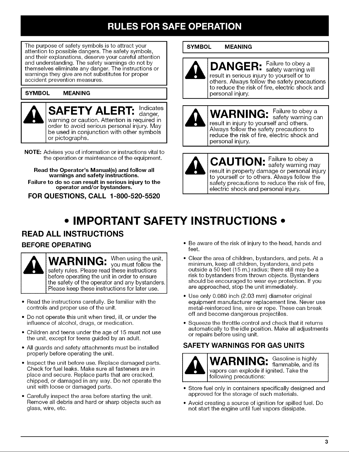
The purpose of safety symbols is to attract your
attention to possible dangers. The safety symbols,
and their explanations, deserve your careful attention
and understanding. The safety warnings do not by
themselves eliminate any danger. The instructions or
warnings they give are not substitutes for proper
accident prevention measures.
SYMBOL MEANING
I SYMBOL MEANING I
DANGER: Failure to obey a
result in serious injury to yourself or to
others. Always follow the safety precautions
to reduce the risk of fire, electric shock and
personal injury.
safety warning will
SAFETY ALERT: Indicates
warning or caution. Attention is required in
order to avoid serious personal injury. May
be used in conjunction with other symbols
or pictographs.
NOTE: Advises you of information or instructions vital to
the operation or maintenance of the equipment.
Read the Operator's Manual(s) and follow all
warnings and safety instructions.
Failure to do so can result in serious injury to the
operator and/or bystanders.
danger,
FOR QUESTIONS, CALL 1-800-520-5520
• IMPORTANT SAFETY INSTRUCTIONS •
READ ALL INSTRUCTIONS
BEFORE OPERATING
WARNING: When using the unit,
safety rules. Please read these instructions
before operating the unit in order to ensure
the safety of the operator and any bystanders.
Please keep these instructions for later use.
• Read the instructions carefully. Be familiar with the
controls and proper use of the unit.
• Do not operate this unit when tired, ill, or under the
influence of alcohol, drugs, or medication.
• Children and teens under the age of 15 must not use
the unit, except for teens guided by an adult.
• All guards and safety attachments must be installed
properly before operating the unit.
• Inspect the unit before use. Replace damaged parts.
Check for fuel leaks. Make sure all fasteners are in
place and secure. Replace parts that are cracked,
chipped, or damaged in any way. Do not operate the
unit with loose or damaged parts.
• Carefully inspect the area before starting the unit.
Remove all debris and hard or sharp objects such as
glass, wire, etc.
you must follow the
WARNING: Failure to obey a
result in injury to yourself and others.
Always follow the safety precautions to
reduce the risk of fire, electric shock and
personal injury.
CAUTION: safety warning may
result in property damage or personal injury
to yourself or to others. Always follow the
safety precautions to reduce the risk of fire,
electric shock and personal injury.
Be aware of the risk of injury to the head, hands and
feet.
Clear the area of children, bystanders, and pets. At a
minimum, keep all children, bystanders, and pets
outside a 50 feet (15 m.) radius; there still may be a
risk to bystanders from thrown objects. Bystanders
should be encouraged to wear eye protection. If you
are approached, stop the unit immediately.
Use only 0.080 inch (2.03 mm) diameter original
equipment manufacturer replacement line. Never use
metal-reinforced line, wire or rope. These can break
off and become dangerous projectiles.
Squeeze the throttle control and check that it returns
automatically to the idle position. Make all adjustments
or repairs before using unit.
safety warning can
Failure to obey a
SAFETY WARNINGS FOR GAS UNITS
WARNING: Gasoline is highly
vapors can explode if ignited. Take the
following precautions:
• Store fuel only in containers specifically designed and
approved for the storage of such materials.
• Avoid creating a source of ignition for spilled fuel. Do
not start the engine until fuel vapors dissipate.
flammable, and its
• Alwaysstoptheengineandallowittocoolbeforefilling
thefueltank.Neverremovethecapofthefueltank,or
addfuel,whentheengineishot.Neveroperatetheunit
withoutthefuelcapsecurelyinplace.Loosenthefuel
tankcapslowlytorelieveanypressureinthetank.
• Mixandaddfuelinaclean,well-ventilatedoutdoorarea
wheretherearenosparksorflames.Slowlyremovethe
fuelcaponlyafterstoppingengine.Donotsmokewhile
fuelingormixingfuel.Wipeupanyspilledfuelfromthe
unitimmediately.Alwayswipeunitdrybeforeusing.
• Movetheunitatleast30feet(9.1m)fromthefueling
sourceandsitebeforestartingtheengine.Donot
smokeorallowsparksandopenflamesnearthearea
whileaddingfueloroperatingtheunit.
WHILE OPERATING
• Never start or run the unit inside a closed room or
building. Breathing exhaust fumes can kill. Operate
this unit only in a well ventilated outdoor area.
• Wear safety glasses or goggles that are marked as
meeting ANSI Z87.1-1989 standards. Also wear
ear/hearing protection when operating this unit. Wear
a face or dust mask if the operation is dusty. Long
sleeve shirts are recommended.
• Wear heavy, long pants, boots and gloves. Do not
wear loose clothing, jewelry, short pants, sandals or
go barefoot. Secure hair above shoulder level.
• The cutting attachment shield must always be in place
while operating the unit. Do not operate unit without
both trimming lines extended, and the proper line
installed. Do not extend the trimming line beyond the
length of the shield.
• This unit has a clutch. The cutting attachment remains
stationary when the engine is idling. If it does not, have
the unit adjusted by an authorized service technician.
• Adjust the D-handle to your size to provide the best
grip.
• Be sure the cutting attachment is not in contact with
anything before starting the unit.
• Use the unit only in daylight or good artificial light.
• Avoid accidental starting. Be in the starting position
whenever pulling the starter rope. The operator and
unit must be in a stable position while starting. See
Starting/Stopping Instructions.
• Use the right tool. Only use this tool for the purpose
intended.
• Do not overreach. Always keep proper footing and
balance.
• Always hold the unit with both hands when operating.
Keep a firm grip on both the front and rear handle or
grips.
Keep hands, face, and feet at a distance from all
moving parts. Do not touch or try to stop the cutting
attachment when it is rotating.
Do not touch the engine or muffler. These parts get
extremely hot from operation. They remain hot for a
short time after you turn off the unit.
Do not operate the engine faster than the speed
needed to cut, trim or edge. Do not run the engine at
high speed when you are not cutting.
Always stop the engine when cutting is delayed or
when walking from one cutting location to another.
If you strike or become entangled with a foreign
object, stop the engine immediately and check for
damage. Do not operate before repairing damage. Do
not operate the unit with loose or damaged parts.
Stop and switch the engine to off for maintenance,
repair, or for changing the cutting attachment or other
attachments.
Use only original equipment manufacturer
replacement parts and accessories for this unit. These
are available from your authorized service dealer. Use
of any unauthorized parts or accessories could lead to
serious injury to the user, or damage to the unit, and
void your warranty.
Keep unit clean of vegetation and other materials.
They may become lodged between the cutting
attachment and shield.
• To reduce fire hazard, replace faulty muffler and spark
arrestor, keep the engine and muffler free from grass,
leaves, excessive grease or carbon build up.
OTHER SAFETY WARNINGS
• Never store the unit, with fuel in the tank, inside a
building where fumes may reach an open flame or
spark.
• Allow the engine to cool before storing or transporting.
Be sure to secure the unit while transporting.
• Store the unit in a dry area, locked up or up high
to prevent unauthorized use or damage, out of the
reach of children.
Never douse or squirt the unit with water or any other
liquid. Keep handles dry, clean and free from debris.
Clean after each use. See the Cleaning and Storage
instructions.
• Keep these instructions. Refer to them often and use
them to instruct other users. If you loan someone this
unit, also loan them these instructions.
SAVE THESE
INSTRUCTIONS
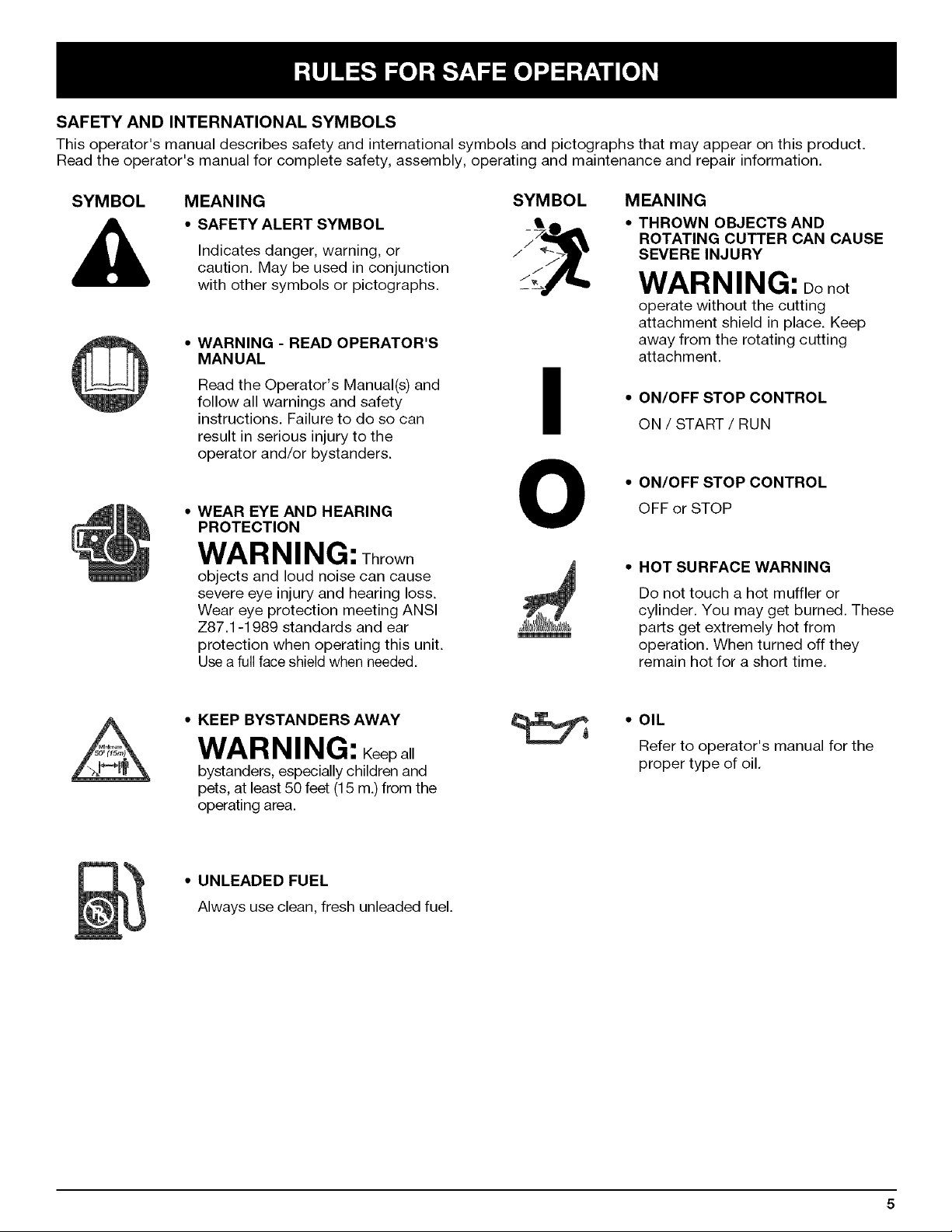
SAFETY AND INTERNATIONAL SYMBOLS
This operator's manual describes safety and international symbols and pictographs that may appear on this product.
Read the operator's manual for complete safety, assembly, operating and maintenance and repair information.
SYMBOL MEANING SYMBOL
• SAFETY ALERT SYMBOL •
Indicates danger, warning, or
caution. May be used in conjunction
with other symbols or pictographs. /_
• WARNING - READ OPERATOR'S
MANUAL
Read the Operator's Manual(s) and
follow all warnings and safety
instructions. Failure to do so can
result in serious injury to the
operator and/or bystanders.
WEAR EYE AND HEARING
PROTECTION
I
O
WARNING: Thrown
objects and loud noise can cause
severe eye injury and hearing loss.
Wear eye protection meeting ANSI
Z87.1-1989 standards and ear
protection when operating this unit.
Use a full face shield when needed.
MEANING
• THROWN OBJECTS AND
ROTATING CUTTER CAN CAUSE
SEVERE INJURY
WARNING: Do not
operate without the cutting
attachment shield in place. Keep
away from the rotating cutting
attachment.
• ON/OFF STOP CONTROL
ON / START / RUN
• ON/OFF STOP CONTROL
OFF or STOP
• HOT SURFACE WARNING
Do not touch a hot muffler or
cylinder. You may get burned. These
parts get extremely hot from
operation. When turned off they
remain hot for a short time.
• KEEP BYSTANDERS AWAY
WARNING: Keep all
bystanders, especially children and
pets, at least 50 feet (15 m.) from the
operating area.
• UNLEADED FUEL
Always use clean, fresh unleaded fuel.
• OIL
Refer to operator's manual for the
proper type of oil.

APPLICATIONS
Asatrimmer:
• Cuttinggrassandlightweeds.
• Edging
• Decorativetrimmingaroundtrees,fences,etc.
Otheroptionalaccessoriesmaybeusedwiththe
TB20CS.RefertoOperating the EZ-Link System for
a list of add-ons.
Air Filter/Muffler Blue Choke
Cover Lever
Blue Choke Lever
Fuel Cap
Starter Ro
Muffler
Spark Plug
Engine Muffler
Stand Spark Plug Primer Bulb
On/Off Stop
Control
D-Handle
Cutting Attachment
Shield
Shaft Grip
Throttle
Control
Shaft Housing
EZ-Link TM
Line Cutting Blade
\
Cutting Attachment
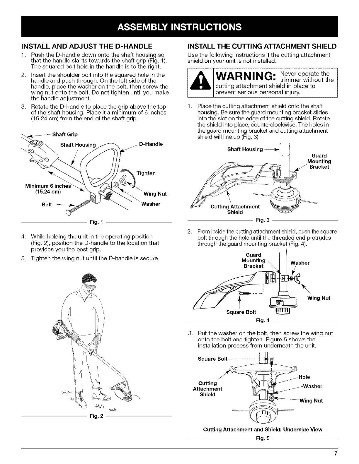
INSTALL AND ADJUST THE D-HANDLE
1. Push the D-handle down onto the shaft housing so
that the handle slants towards the shaft grip (Fig. 1).
The squared bolt hole in the handle is to the right.
2. Insert the shoulder bolt into the squared hole in the
handle and push through. On the left side of the
handle, place the washer on the bolt, then screw the
wing nut onto the bolt. Do not tighten until you make
the handle adjustment.
3. Rotate the D-handle to place the grip above the top
of the shaft housing. Place it a minimum of 6 inches
(15.24 cm) from the end of the shaft grip.
D-Handle
Tighten
Minimum
(15.24 cm) Wing Nut
INSTALL THE CUI-I'ING ATI'ACHMENT SHIELD
Use the following instructions if the cutting attachment
shield on your unit is not installed.
IAIAD I 11 • Never operate the
I • • rim • n• mn• _ • trimmer without the
cutting attachment shield in place to
prevent serous persona njury.
Place the cutting attachment shield onto the shaft
housing. Be sure the guard mounting bracket slides
into the slot on the edge of the cutting shield. Rotate
the shield into place, counterclockwise. The holes in
the guard mounting bracket and cutting attachment
shield will line up (Fig. 3).
Shaft Housing
Guard
Mounting
Bracket
Bolt _ Washer
Fig. 1
4. While holding the unit in the operating position
(Fig. 2), position the D-handle to the location that
provides you the best grip.
5. Tighten the wing nut until the D-handle is secure.
Cutting Attachment
Shield
Fig. 3
.
From inside the cutting attachment shield, push the square
bolt through the hole until the threaded end protrudes
through the guard mounting bracket (Fig. 4).
Guard
Mounting
Bracket
isher
Wing Nut
f
Square Bolt
Fig. 4
3. Put the washer on the bolt, then screw the wing nut
onto the bolt and tighten. Figure 5 shows the
installation process from underneath the unit.
Square Bo_
Fig. 2
Cutting //\ II r , .
Attachment //_ _ L,_ wasner
Shield _- It =
-/ _J _-_Win- Nut
Cutting Attachment and Shield: Underside View
Fig. 5
 Loading...