

Troybilt TB90BC, 41BDT90C063, 41ADT90C063 Owner’s Manual

n n mm m mum
Operator's Manual
2 -Cycle Gasoline
Brushcutter
Model TB90BC
IMPORTANT: READ SAFETY RULES AND INSTRUCTIONS CAREFULLY
P/N 769-00662 (3/03)
PRINTED IN USA

Content Page
Calling Customer Support .....................................................
Rules for Safe Operation ..................................................... 3
Z,now Your Unit ........................................................... 7
Assembly Instructions ....................................................... 8
Oil and Fuel Information ..................................................... 11
Starting/Stopping Instructions ............................................ 12
Operating Instructions ...................................................... 13
Maintenance and Repair Instructions .......................................... 16
Cleaning and Storage ....................................................... 21
Accessories and Replacement Parts ........................................... 21
Troubleshooting Chart ...................................................... 22
Specifications ........................................................... 23
Warranty Information ....................................................... 26
Parts Dst .................................................... Inside Back Cover
NOTE: For users on U.S. Forest Land and in the states of California, Maine, Oregon and Washington. All U.S. Forest Land and the state of
California (Public Resources Codes 4442 and 4443), Oregon and Washington require_ by law that certain internal combustion engines operated
on forest brush and/or grass-covered areas be equipped with a spark arrestor, maintained in effective working order, or the engine be
constructed, equipped and maintained for the prevention of fire. Check with your state or local authorities for regulations pertaining to these
requirements. Failure to follow these requirements could subject you to liability or a fine, This unit is factory equipped with a spark arrestor, !f
it requires replacement, Accessory Part #182747 Spark Arrestor Screen is available by contacting the service department.
This operator's manual is an important part of your new trimmer. It will help you assemble, prepare and maintain the unit
for best performance. Please read and understand what it says.
Before you start assembling your new equipment, please locate the model plate on the equipment and copy the
information from it in the space provided below. This information is very important if you need help from our Customer
Support Department or an authorized dealer.
Serial Numb Model Number
ParentPertNumber
Copy the model and parent
part number here:
S/N: ITEM:
lilllllllllllBIllllHBIIIIIIIllllllll€opy,h0s0,,0,n0mborher0:
If you have difficulty assembling this product or have any questions regarding the controls, operation or maintenance of
this unit, please call the Customer Support Department.
Call 1-800-520-5520 to reach a Customer Support representative. Please have your unit's model number
f/_ and serial number ready when you call. See the previous section to locate this information. You will be asked
to enter the serial number in order to process your call.
2
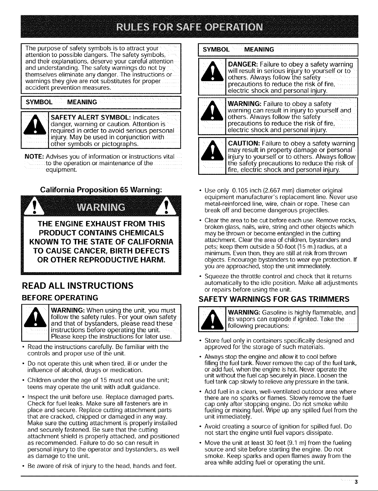
The purpose of safety symbols is to attract your
attention to possible dangers. The safety symbols,
and their explanations, deserve your careful attention
and understanding. The safety warnings do not by
themselves eliminate any danger. The instructions or
warnings they give are not substitutes for proper
accident prevention measures.
SYMBOL MEANING
_ I L SAFETY ALERT SYMBOL: Indicates
NOTE: Advises you of information or instructions vital
danger, warning or caution. Attention is
required in order to avoid serious personal
injury. May be used in conjunction with
other symbols or pictographs.
to the operation or maintenance of the
equepment.
SYMBOL MEANING
_;L DANGER: Failure to 0bey a safetywaming
_L WARNING: Failureto obey a safety
4Bli
_ ' L CAUTION: Failure to 0bey a safety warning
will result in serious injury to yourself or to
others. Always follow the safety
precautions to reduce the risk of fire,
electric shock and personal injury.
warning Can result in injury to yourself and
others. Always follow the safety
precautions to reduce the risk of fire,
electric shock and personal injury.
may result in property damage or personal
injury to yourself or to others. Always follow
the safety precautions to reduce the risk of
fire, electric shock and personal injury.
California Proposition 65 Warning:
THE ENGINE EXHAUST FROM THIS
PRODUCT CONTAINS CHEMICALS
KNOWN TO THE STATE OF CALIFORNIA
TO CAUSE CANCER, BIRTH DEFECTS
OR OTHER REPRODUCTIVE HARM.
READ ALL INSTRUCTIONS
BEFORE OPERATING
A WARNING:When usingthe unit, you must I
A_I, follow the safety rules.For your own safety
and that of bystanders, please read these I
I instructions before operating the unit. I
P ease keep the nstruct ons for ater use. J
• Read the instructions carefully. Be familiar with the
controls and proper use of the unit.
• Do not operate this unit when tired, ill or under the
influence of alcohol, drugs or medication.
• Children under the age of 15 must not use the unit;
teens may operate the unit with adult guidance.
• Inspect the unit before use. Replace damaged parts.
Check for fuel leaks. Make sure all fasteners are in
place and secure. Replace cutting attachment parts
that are cracked, chipped or damaged in any way.
Make sure the cutting attachment is properly installed
and securely fastened. Be sure that the cutting
attachment shield is properly attached, and positioned
as recommended. Failure to do so can result in
personal injury to the operator and bystanders, as well
as damage to the unit.
• Be aware of risk of injury to the head, hands and feet.
• Use only 0.105 inch (2.667 mm) diameter original
equipment manufacturer's replacement line. Never use
metal-reinforced line, wire, chain or rope. These can
break off and become dangerous projectiles.
• Clear the area to be cut before each use. Remove rocks,
broken glass, nails, wire, string and other objects which
may be thrown or become entangled in the cutting
attachment. Clear the area of children, bystanders and
pets; keep them outside a 50-foot (15 m.) radius, at a
minimum. Even then, they are still at risk from thrown
objects. Encourage bystanders to wear eye protection. If
you are approached, stop the unit immediately.
• Squeeze the throttle control and check that it returns
automatically to the idle position. Make all adjustments
or repairs before using the unit.
SAFETY WARNINGS FOR GAS TRIMMERS
i_I WARNING: Gasoline is highly flammable, and ]
• Store fuel only in containers specifically designed and
approved for the storage of such materials.
• Always stop the engine and allow it to cool before
filling the fuel tank. Never remove the cap of the fuel tank,
or add fuel, when the engine is hot. Never operate the
unit without the fuel cap securely in place. Loosen the
fuel tank cap slowly to relieve any pressure in the tank.
• Add fuel in a clean, well-ventilated outdoor area where
there are no sparks or flames. Slowly remove the fuel
cap only after stopping engine. Do not smoke while
fueling or mixing fuel. Wipe up any spilled fuel from the
unit immediately.
• Avoid creating a source of ignition for spilled fuel. Do
not start the engine until fuel vapors dissipate.
• Move the unit at least 30 feet (9.1 m) from the fueling
source and site before starting the engine. Do not
smoke. Keep sparks and open flames away from the
area while adding fuel or operating the unit.
its Vapors Can explode if ignited. Take the |
following precautions: ]
3

WHILE OPERATING
• Never start or run the unit inside a closed room or
building. Breathing exhaust fumes can be fatal.
Operate this unit only in a well-ventilated outdoor area.
• Wear safety glasses or goggles that meet ANSI Z87.1
standards and are marked as such. Wear ear/hearing
protection when operating this unit. Wear a face or
dust mask if the operation is dusty.
• Wear heavy long pants, boots, gloves and a long
sleeve shirt. Do not wear loose clothing, jewelry, short
pants, sandals or go barefoot. Secure hair above
shoulder level.
• The cutting attachment shield must always be in place
while operating the unit as a trimmer. Do not operate
unit without both trimming lines extended, and the
proper line installed. Do not extend the trimming line
beyond the length of the shield.
• This unit has a clutch. The cutting attachment remains
stationary when the engine is idling. If it does not, have
the unit adjusted by an authorized service technician.
• Adjust the J-handle to your size in order to provide the
best grip.
• Be sure the cutting attachment is not in contact with
anything before starting the unit.
• Use the unit only in daylight or good artificial light.
• Avoid accidental starting. Be in the starting position
whenever pulling the starter rope. The operator and
unit must be in a stable position while starting. Refer
to Starting/Stopping Instructions.
• Use the right tool. Only use this tool for its intended
purpose.
• Do not overreach. Always keep proper footing and
balance.
• Always hold the unit with both hands when operating.
Keep a firm grip on both handles or grips.
• Keep hands, face, and feet at a distance from all
moving parts. Do not touch or try to stop the cutting
attachment when it rotates.
• Do not touch the engine, gear housing or muffler.
These parts get extremely hot from operation, even
after the unit is turned off.
• Do not operate the engine faster than the speed
needed to cut, trim or edge. Do not run the engine at
high speed when not cutting.
• Always stop the engine when cutting is delayed or
when walking from one cutting location to another.
• If you strike or become entangled with a foreign
object, stop the engine immediately and check for
damage. Do not operate before repairing damage. Do
not operate the unit with loose or damaged parts.
• Stop the unit, switch the engine to off, and disconnect
the spark plug for maintenance or repair.
• Use only original equipment manufacturer replacement
parts and accessories for this unit. These are available
from your authorized service dealer. Use of any
unauthorized parts or accessories could lead to
serious injury to the user, or damage to the unit, and
void your warranty.
• Keep unit clean of vegetation and other materials.
They may become lodged between the cutting
attachment and shield.
• To reduce fire hazard, replace a faulty muffler and
spark arrestor. Keep the engine and muffler free from
grass, leaves, excessive grease or carbon build up.
WHILE OPERATING WITH CUTTING BLADE
• Read and understand all safety warnings before
operating this unit.
• Always use the shoulder harness when using the
brush blade accessory.
• Keep the J-handle between the operator and cutting
attachment or blade at all times.
• NEVER cut when the cutting blade is 30 inches
(76 cm) or more above the ground level.
• Blade thrust may occur when the spinning blade
contacts an object that it does not immediately cut.
Blade thrust can be violent enough to propel the unit
and/or operator in any direction, possibly causing a
loss of control. Blade thrust can occur without warning
if the blade snags, stalls or binds. This is more likely to
occur in areas where it is difficult to see the material
being cut.
• For operation with the brush blade, do not cut
anything thicker than 1/2 inch or a violent kickback
could occur.
• Do not attempt to touch or stop the blade when it is
rotating.
• A coasting blade can cause injury while it continues to
spin after the engine is stopped or the throttle trigger
is released. Maintain proper control until the blade has
completely stopped rotating.
4

• Do not run the unit at high speed when not cutting.
• if you strike or become entangled with a foreign
object, stop the engine immediately and check for
damage. Have any damage repaired before attempting
further operations. Do not operate unit with a bent,
cracked or dull blade. Discard blades that are bent,
warped, cracked or broken.
• Do not sharpen the cutting blade. Sharpening the blade
can cause the blade tip to break off while in use. This
can result in severe personal injury. Replace the blade.
• Do not use the cutting blade for edging or as an edger;
severe personal injury to yourself or others may incur.
Use the cutting blade only for the purpose described
in this manual.
• Stop the engine IMMEDIATELY if you feel excessive
vibration. Vibration is a sign of trouble. Inspect
thoroughly for loose nuts, bolts or damage before
continuing. Repair or replace affected parts as
necessary.
After Use
• Clean cutting blades with a household cleaner to
remove any gum buildup. Oil the blade with machine
oil to prevent rust.
• Lock up and store the cutting blade _nan appropriate
area to protect the blade from unauthonzed use or
damage.
OTHER SAFETY WARNINGS
• Never store a fueled unit inside a building where fumes
may reach an open flame or spark.
• Allow the engine to cool before storing or transporting.
Be sure to secure the unit while transporhng.
• Store the unit in a dry area, ocked up or up high to
prevent unauthorized use or damage, out of the reach
of children.
Never douse or squirt the unit with water or any other
iquid. Keep handles dry, clean and free from debris
Clean after each use see Cleaning and Storage
nstructlons
• Keep these instruct_ons. Refer to them often and use
them to instruct other users. If you loan someone this
Jnit also loan them these instructions.
SAVE THESE INSTRUCTIONS
5

SAFETY AND INTERNATIONAL SYMBOLS
This operator's manual describes safety and international symbols and pictographs that may appear On this product.
Read the operator's manual for complete safety, assembly, operating and maintenance and repair information.
SYMBOL MEANING SYMBOL MEANING
• ON/OFF STOP CONTROL
Indicates danger, warning or caution.
• SAFETY ALERT SYMBOL O
May be used in conjunction with other
symbols or pictographs.
• WARNING - READ - Y,ilk_
OFF or STOP
• THROWN OBJECTS AND
ROTATING CUTTER CAN
CAUSE SEVERE INJURY
O OPERATOR'S MANUAL / _-
I
Read the operator's manual(s) and follow _/
all warnings and safety instructions.
Failureto do so can result in serious injury
to the operator and/or bystanders.
• WEAR EYE AND HEARING
WARNING: Thrown objects and loud
noise can cause severe eye injury and
PROTECTION
hearing loss. Wear eye protection
meeting ANSI Z87.1 standards and ear
protection when operating this unit.
Use a full face shield when needed.
• KEEP BYSTANDERS AWAY
WARNING: Keep all bystanders,
especially children and pets, at least
50 feet (15 m) from the operating area.
• UNLEADED FUEL
Always use clean, fresh unleaded fuel.
• OIL
Refer to operator's manual for the
proper type of oil.
• ON/OFF STOP CONTROL
ON /START / RUN
WARNING: Do not operate without
the cutting attachment shield in place.
Keep away from the rotating cutting
attachment.
• HOT SURFACE WARNING
Do not touch a hot muffler, gear housing
or cylinder. You may get burned. These
parts get extremely hot from operation.
They remain hot for a short time after the
unit is turned off.
• SHARP BLADE
WARNING: Sharp blade on cutting
attachment shield. To prevent serious
injury, do not touch line cutting blade.
• BRUSHCUTTERS • REPLACE
DULL BLADE
Do not sharpen the cutting blade.
Sharpening the blade can cause the
blade tip to break off while in use. This
can result in severe personal injury.
oTRIMMER/BRUSHCUTTER
SAFETY
WARNING: Thrown objects and
rotating cutter can cause severe injury.
Keep bystanders, especially children
and pets, at least 50 feet (15 m) away
from the cutting area. The cutting
attachment shield must be used when
using the trimmer cutting attachment.
6
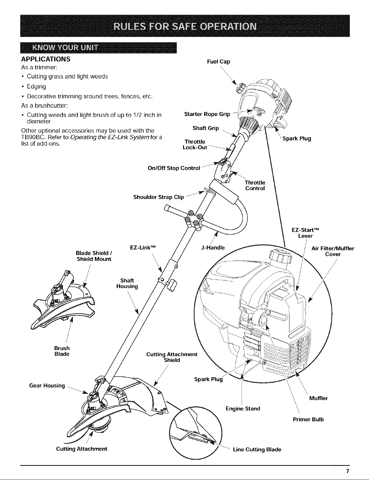
APPLICATIONS
As a trimmer:
• Cutting grass and light weeds
• Edging
• Decorative trimming around trees, fences, etc.
As a brushcutter:
• Cutting weeds and light brush of up to 1/2 inch in
diameter
Other optional accessories may be used with the
TB90BC. Refer to Operating the EZ-Link System for a
list of add-ons.
Shoulder Strap Clip
Fuel Cap
\\\\
\\
Starter Rope Grip
Shaft Grip -_
Throttle
Lock-Out
Throttle
Control
EZ.Start TM
Lever
Brush
Blade
Gear Housing ._
Blade Shield /
Shield Mount
EZ.Link TM
Shaft
Housing
\
'\
\
\
\
\
Cutting Attachment
Shield
J-Handle
Spark Plug
Engine Stand
Air Filter/Muffler
\ Muffler
\
\
Primer Bulb
Cover
Cutting Attachment
Line Cutting Blade
7
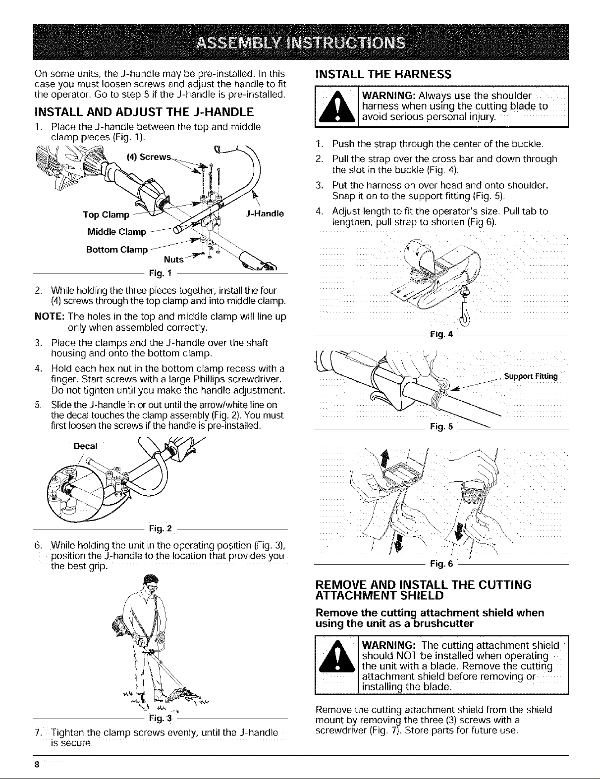
On some units, the J-handle may be pre-installed. In this
case you must loosen screws and adjust the handle to fit
the operator. Go to step 5 if the J-handle is pre-installed.
INSTALL AND ADJUST THE J-HANDLE
1. Place the J-handle between the top and middle
clamp pieces (Fig. 1).
(4)
Top Clamp J-Handle
Middle Clamp
INSTALL THE HARNESS
WARNING: Always use the shoulder I
harness when using the cutting blade to
avo d serous persona njury. J
1. Push the strap through the center of the buckle.
2. Pull the strap over the cross bar and down through
the slot in the buckle (Fig. 4).
3. Put the harness on over head and onto shoulder.
Snap it on to the support fitting (Fig. 5).
4.
Adjust length to fit the operator's size. Pull tab to
lengthen, pull strap to shorten (Fig 6).
Bottom Clamp Nuts_,_,
Fig. 1
2. While holding the three pieces together, install the four
(4) screws through the top clamp and into middle clamp.
NOTE: The holes in the top and middle clamp will line up
only when assembled correctly.
3. Place the clamps and the J-handle over the shaft
housing and onto the bottom clamp.
4. Hold each hex nut in the bottom clamp recess with a
finger. Start screws with a large Phillips screwdriver.
Do not tighten until you make the handle adjustment.
5. Slide the J-handle in or out until the arrow/white lineon
the decal touches the clamp assembly (Fig. 2).You must
first loosen the screws if the handle is pre-installed.
Fig. 2
6. While holding the unit in the operating position (Fig. 3),
position the J-handle to the location that provides you
the best grip.
)
Fig. 4
_ Support Fitting
Fig. 6
REMOVE AND INSTALL THE CUTTING
ATTACHMENT SHIELD
Fig. 3
7. Tighten the clamp screws evenly, until the J-handle
is secure.
8
Remove the cuttingattachment shield when
using the unit as abrushcutter
A WARNING: The cutting attachment shield
_,lh, should NOT be installed when operating I
the unit with a blade. Remove the cutting
attachment shield before removing or
installing the blade. I
Remove the cutting attachment shield from the shield
mount by removing the three (3)screws with a
screwdriver (Fig. 7). Store parts for future use.
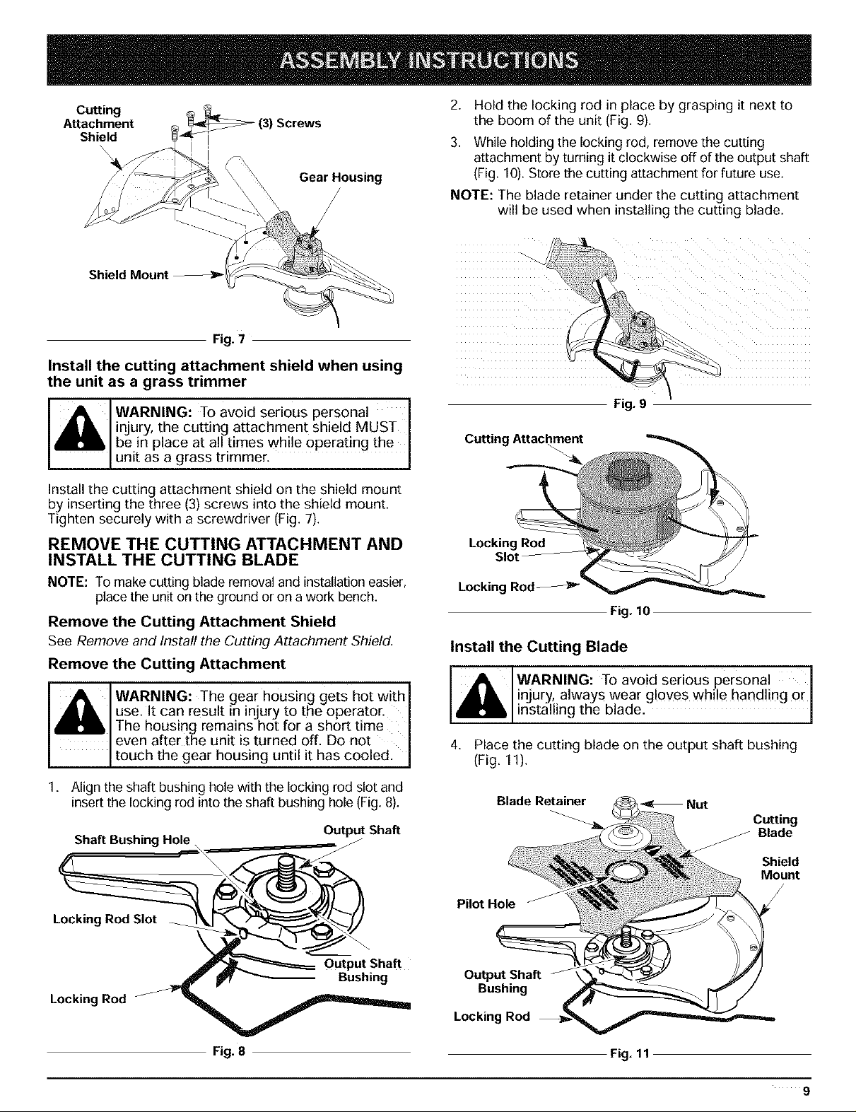
Cutting
Attachment
Shield
Shield
Fig. 7
Screws
Gear Housing
Install the cutting attachment shield when using
the unit as a grass trimmer
WARNING: To avoid serious personal 1
injury, the cutting attachment shield MUST
be in place at all times while operating the I
unit as a grass trimmer. J
Install the cutting attachment shield on the shield mount
by inserting the three (3) screws into the shield mount.
Tighten securely with a screwdriver (Fig. 7).
REMOVE THE CUTTING ATTACHMENT AND
INSTALL THE CUTTING BLADE
NOTE: To make cutting blade removal and installation easier,
place the unit onthe ground or on a work bench.
Remove the Cutting Attachment Shield
See Remove and Install the Cutting Attachment Shield.
Remove the Cutting Attachment
WARNING: The gear housing gets hot with 1
use. It can result in injury to the operator. I
The housing remains hot for a short time
even after the unit is turned off. Do not I
touch thegear hous!ng until !thas coo!ed: J
2. Hold the locking rod in place by grasping it next to
the boom of the unit (Fig. 9).
3. While holding the locking rod, remove the cutting
attachment by turning it clockwise off of the output shaft
(Fig. 10). Store the cutting attachment for future use.
NOTE: The blade retainer under the cutting attachment
will be used when installing the cutting blade.
Fig. 9
Cutting Attachment
Locking Rod
Slot
Locking Rod
Fig. 10
Install the Cutting Blade
WARNING: TOavoid serious personal
injury, always wear gloves while handling or
installing the blade. I
4. Place the cutting blade on the output shaft bushing
(Fig. 11).
1. Align the shaft bushing hole with the locking rod slot and
insert the locking rod into the shaft bushing hole (Fig. 8).
Output Shaft
Shaft Bushing Hole
LOC , RodS,ot
Output Shaft
Locking Rod
Fig. 8
Blade Retainer _ Nut
Cutting
Blade
Shield
Mount
Pilot Hole
Output Shaft
Bushing
Locking Rod
Fig. 11
9
 Loading...