

Page 1

TRnV:BILT
m iwm m mmm r®
Operator's Manual
4-Cycle Gasoline
Trimmer / Brushcutter
Model TB490BC
IMPORTANT:READ SAFETY RULES AND INSTRUCTIONS CAREFULLY
NOTE: For users on U,S, Forest Land and in the states of California. Maine, Oregon and Washington. All U.S, Forest Land and the state of California
(Public Resources Codes 4442 and 4443), Oregon and Washington require, by Iaw that certain internal combustion engines operated on forest brush
and/or grass-covered areas be equipped with a spark arrestor, maintained in effective working order, or the engine be constructed, equipped and
maintained for the prevention of fire, Check with your state or local authorities for regulations pertaining to these requirements, Failure to follow these
requirements could subject you to liability or a fine. This unit is factory equipped with a spark arrestor, If it requires replacement, Accessory Part 791-
180890 Spark Arrestor Screen is available by contacting the service department at Troy-Biff LLC, P.O. Box 36t 131 Cleveland, Ohio 44I 36-0019.
TROY-BILT LLC, P.O. BOX 361131, CLEVELAND, OH 44136-0019
P!N 771-10661 (11/01 rev. P00)
PRINTED IN USA
Page 2

Content Page
Calling Customer Support .................................................... 2
Rules for Safe Operation ..................................................... 3
Know Your Unit ............................................................ 7
Assembly Instructions ....................................................... 8
Oil and Fuel Information ..................................................... 11
Starting/Stepping Instructions ................................................. 13
Operating Instructions ....................................................... 14
Maintenance and Repair Instructions ........................................... 17
Accessories and Replacement Parts ........................................... 24
Cleaning and Storage ....................................................... 25
Troubleshooting Chart ....................................................... 26
Specifications ............................................................. 27
Warranty Information ........................................................ 32
This Operator's Manual is an important part of your new Trimmer/Brushcutter. It will help you assemble, prepare and
maintain the unit for best performance. Please read and understand what it says.
Before you start assembling your new equipment, please locate the model plate on the equipment and copy the information
from it in the space provided below. This information is very important if you need help from our Customer Support
Department or an authorized dealer.
• You can locate the model number by looking at the side of the engine housing. A sample model plate is explained
below. For future reference, please copy the model number and the serial number of the equipment in the space
below
Serial Number Model/Parent Part Number
Copy the model / parent part
number here:
Copy the serial number here:
lllllill!,H%r!l!llL,LtL
If you have difficulty assembIing this product or have any questions regarding the controls, operation or maintenance of this
unit, please call the Customer Support Department.
Call 1- (330) 558-7220 or 1- (866) 840-6483 to reach a Customer Support representative. Please have your
unit's model number and serial number ready when you call. See previous section to locate this information.
You will be asked to enter the serial number in order to process your call.
Page 3
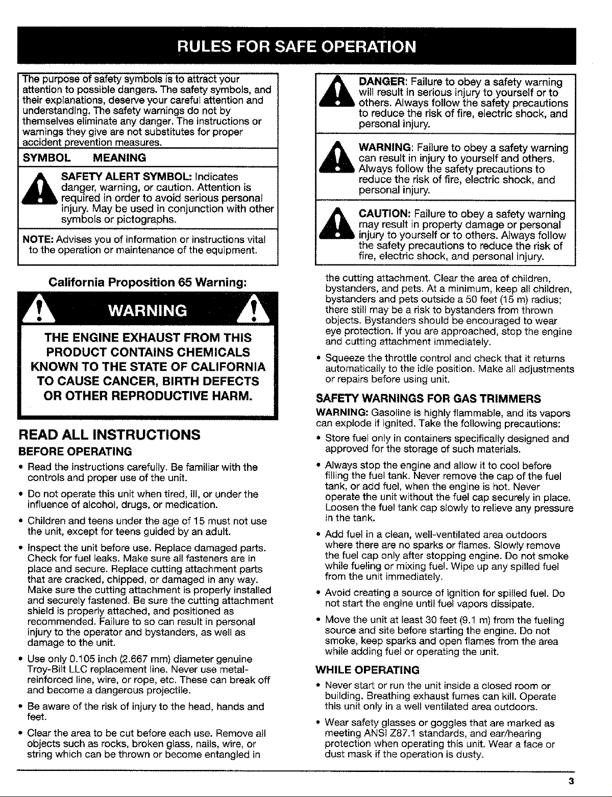
Thepurposeofsafetysymbolsistoattractyour
attentiontopossibledangers.Thesafety symbols, and
their explanations, deserve your careful attention and
understanding. The safety warnings do not by
themselves eliminate any danger. The instructions or
warnings they give are not substitutes for proper
accident prevention measures.
SYMBOL MEANING
SAFETY ALERT SYMBOL: Indicates
danger, warning, or caution. Attention is
required in order to avoid serious personal
injury. May be used in conjunction with other
symbols or pictographs.
NOTE: Advises you of information or instructions vital
to the operation or maintenance of the equipment.
DANGER: Failure to obey a safety warning
will result in serious injury to yourself or to
others. Always follow the safety precautions
to reduce the risk of fire, electric shock, and
personal injury.
WARNING: Failure to obey a safety warning
can result in injury to yourself and others.
Always follow the safety precautions to
reduce the risk of fire, electric shock, and
personal injury.
CAUTION: Failure to obey a safety warning
may result in property damage or personal
injury to yourself or to others. Always fellow
the safety precautions to reduce the risk of
fire, electric shock, and personal injury.
California Proposition 65 Warning:
READ ALL INSTRUCTIONS
BEFORE OPERATING
• Read the instructions carefully. Be familiar with the
controls and proper use of the unit.
• Do not operate this unit when tired, ill, or under the
influence of alcohol, drugs, or medication.
• Children and teens under the age of 15 must not use
the unit, except for teens guided by an adult.
• Inspect the unit before use. Replace damaged parts.
Check for fue! leaks. Make sure all fasteners are in
place and secure. Replace cutting attachment parts
that are cracked, chipped, or damaged in any way.
Make sure the cutting attachment is properly installed
and securely fastened. Be sure the cutting attachment
shield is properly attached, and positioned as
recommended. Failure to so can result in personal
injury to the operator and bystanders, as well as
damage to the unit.
• Use only 0.105 inch (2.667 mm) diameter genuine
Troy-BiIt LLC replacement line. Never use metal-
reinforced line, wire, or rope, etc. These can break off
and become a dangerous projectile.
• Be aware of the risk of injury to the head, hands and
feet.
• Clear the area to be cut before each use. Remove all
objects such as rocks, broken glass, nails, wire, or
string which can be thrown or become entangled in
the cutting attachment. Clear the area of children,
bystanders, and pets. At a minimum, keep all children,
bystanders and pets outside a 50 feet (15 m) radius;
there sdll may be a risk to bystanders from thrown
objects. Bystanders should be encouraged to wear
eye protection. If you are approached, stop the engine
and cutting attachment immediately.
• Squeeze the throttle control and check that it returns
automatically to the idle position. Make all adjustments
or repairs before using unit.
SAFETY WARNINGS FOR GAS TRIMMERS
WARNING: Gasoline is highly flammable, and its vapors
can explode if ignited. Take the following precautions:
• Store fuel only in containers specifically designed and
approved for the storage of such materials.
• Always stop the engine and allow it to cool before
filling the fue_tank. Never remove the cap of the fuel
tank, or add fuel, when the engine is hot. Never
operate the unit without the fuel cap securely in place.
Loosen the fuel tank cap slowly to relieve any pressure
in the tank.
,, Add fueI in a clean, well-ventilated area outdoors
where there are no sparks or flames. Slowly remove
the fuel cap only after stopping engine. Do not smoke
while fueling or mixing fue!. Wipe up any spilled fuel
from the unit immediately,
• Avoid creating a source of ignition for spilled fuel. Do
not start the engine until fuel vapors dissipate.
• Move the unit at least 30 feet (9.1 m) from the fueling
source and site before starting the engine. Do not
smoke, keep sparks and open flames from the area
while adding fuel or operating the unit.
WHILE OPERATING
• Never start or run the unit inside a closed room or
building. Breathing exhaust fumes can kilt. Operate
this unit only in a well ventilated area outdoors.
• Wear safety glasses or goggles that are marked as
meeting ANSI Z87.1 standards, and ear/hearing
protection when operating this unit. Wear a face or
dust mask if the operation is dusty.
3
Page 4

• Wear heavy, long pants, boots, gloves and a long
sleeve shirt. Do not wear loose clothing, jewelry, short
pants, sandals or go barefoot. Secure hair above
shoulder level.
• The cutting attachment shield must always be in place
while operating the unit. Do not operate unit without
both trimming lines extended, and the proper line
installed. Do not extend the trimming line beyond the
length of the shield.
• This unit has a clutch. The cutting attachment remains
stationary when the engine is idling. If it does not, have
the unit adjusted by an authorized service technician.
• Adjust the J-Handle to your size to provide the best
grip.
• Be sure the cutting attachment is not in contact with
anything before starting the unit.
• Use the unit only in daylight or good artificial light.
. Avoid accidental starting. Be in the starting position
whenever pulling the starter rope. The operator and
unit must be in a stable position while starting. See
Starting!Stopping Instructions.
• Use the right tool. Only use this tool for the purpose
intended.
• Do not overreach. Always keep proper footing and
balance.
• Always hold the unit with both hands when operating.
Keep a firm grip on both the front and rear handle or
grips.
,, Keep hands, face, and feet at a distance from all
moving parts. Do not touch or try to stop the cutting
attachment when it is rotating.
• Do not touch the engine, gear housing or muffler,
These parts get extremely hot from operation. When
turned off they remain hot for a short time.
• Do not operate the engine faster than the speed
needed to cut, trim or edge. Do not run the engine at
high speed when not cutting.
• Always stop the engine when cutting is delayed or
when walking from one cutting location to another.
• If you strike or become entangled with a foreign
object, stop the engine immediately and check for
damage. Do not operate before repairing damage. Do
not operate the unit with loose or damaged parts.
• Stop and switch the engine to off for maintenance,
repair, or for changing the cutting attachment or other
attachments.
• Use only genuine manufacturer's replacement parts
and accessories for this unit. These are available from
your authorized service dealer. Use of any non Troy-
Bilt LLC parts or accessories could lead to serious
injury to the user, or damage to the unit, and void your
warranty.
• Keep unit clean of vegetation and other materials.
They may become lodged between the cutting
attachment and shield.
• To reduce fire hazard, replace faulty muffler and spark
arrestor, keep the engine and muffler free from grass,
leaves, excessive grease or carbon build up.
WHILE OPERATING WITH CUTTING BLADE
• Read and understand all safety warnings before
operating this unit.
• Always use the shoulder harness when using the
brush blade accessory.
• Keep the J-handle between the operator and cutting
attachment or blade at all times.
• NEVER cut with the cutting blade located over 30
inches (76 cm) or more above the ground level.
• Blade thrust may occur when the spinning blade
contacts an object that it does not immediately cut.
Blade thrust can be violent enough to cause the unit
and/or operator to be propelled in any direction, and
possibly lose control of the unit. Blade thrust can
occur without warning if the blade snags, stalls or
binds. This is more likely to occur in areas where it is
difficult to see the material being cut.
• For operation with the brush blade, do not cut
anything thicker than 1/2 inch or a violent kickback
could occur.
• Do not attempt to touch or stop the blade when it is
rotating.
A coasting blade can cause injury while it continues to
spin after the engine is stopped or the throttle trigger
is released. Maintain proper control until the blade has
completely stopped rotating.
• Do not run the unit at high speed when not cutting,
• If you strike or become entangled with a foreign
object, stop the engine immediately and check for
damage. Have any damage repaired before attempting
further operations. De not operate unit with a bent,
cracked or dull blade. Discard blades that are bent,
warped, cracked or broken.
• Do not sharpen the cutting blade. Sharpening the
blade can cause the blade tip to break off while in use.
This can result in severe personal injury. Replace the
blade.
• Do not use the cutting blade for edging or as an
edger, severe personal injury to yourself or others can
occur. Use the cutting blade only for the purpose as
described in this manual.
• Stop the engine IMMEDIATELY if you feel excessive
vibration. Vibration is a sign of trouble. Inspect
thoroughly for loose nuts, bolts or damage before
continuing. Repair or replace affected parts as
necessary.
AFTER USE
• Clean cutting blades with a household cleaner to
remove any gum buildup. Oil the blade with machine
oil to prevent rust.
• Lock up and store the cutting blade in an appropriate
area to protect the blade from unauthorized use or
damage.
Page 5

OTHER SAFETY WARNINGS
• Never store the unit, with fuel in the tank, inside a
building where fumes may reach an open flame or
spark.
• Allow the engine to cool before storing or transporting.
Be sure to secure the unit while transporting.
• Store the unit in a dry area, locked up or up high
to prevent unauthorized use or damage, out of the
reach of children.
SAFETY AND INTERNATIONAL SYMBOLS
This operator's manual describes safety and international symbols and pictographs that may appear on this product.
Read the operator's manual for complete safety, assembly, operating and maintenance and repair information.
SYMBOL MEANING
• SAFETY ALERT SYMBOL
Indicates danger, warning, or caution, May be used in conjunction with other
symbols or pictographs.
• WARNING - READ OPERATOR'S MANUAL
Read the Operator's Manual(s) and follow all warnings and safety instructions.
Failure to do so can result in serious injury to the operator and/or bystanders.
• Never douse or squirt the unit with water or any other
liquid. Keep handles dry, clean and free from debris.
Clean after each use, see Cleaning and Storage
instructions.
• Keep these instructions. Refer to them often and use
them to instruct other users. If you loan someone this
unit, also loan them these instructions+
SAVE THESE INSTRUCTIONS
i
e
5-7x
• FOR SERVICE INFORMATION, CALL:
1-866-840-6483 or
1-330-558-7220
• WEAR EYE AND HEARING PROTECTION
WARNING: Thrown objects and loud noise can cause severe eye injury and hearing loss.
Wear eye protection meeting ANSI Z87.1 standards and ear protection when
operating this unit.
• KEEP BYSTANDERS AWAY
WARNING: Keep all bystanders, especially children and pets, at least 50 feet (15 m)
from the operating area.
• PRIMER BULB
Push primer bulb, fully and slowly, 5 to 7 times.
• UNLEADED FUEL
Always use clean, fresh unleaded fue!.
5
Page 6
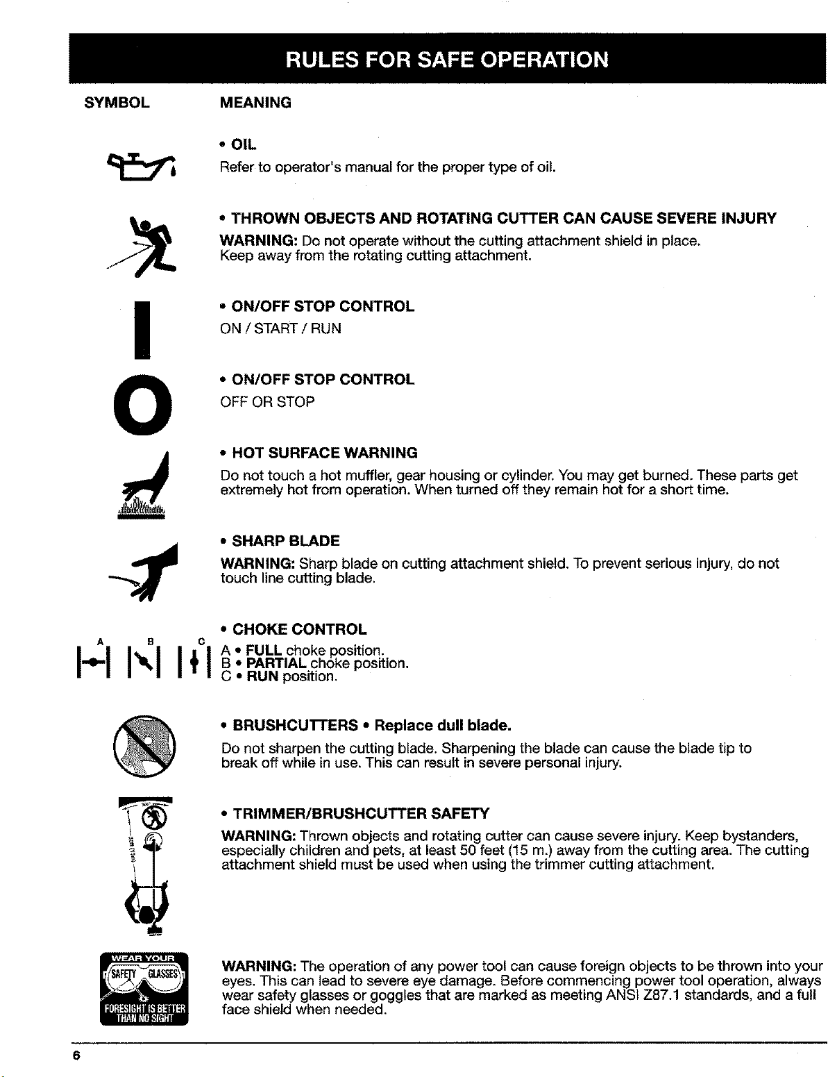
SYMBOL MEANING
• OIL
Refer to operator's manual for the proper type of oil.
* THROWN OBJECTS AND ROTATING CUTTER CAN CAUSE SEVERE INJURY
WARNING: Do not operate without the cutting attachment shield in place,
Keep away from the rotating cutting attachment.
• ON/OFF STOP CONTROL
ON / START / RUN
• ON/OFF STOP CONTROL
OFF OR STOP
• HOT SURFACE WARNING
Do not touch a hot muffler, gear housing or cylinder. You may get burned. These parts get
extremely hot from operation. When turned off they remain hot for a short time.
• SHARP BLADE
WARNING: Sharp blade on cutting attachment shield. To prevent serious injury, do not
touch line cutting blade.
A B C
I+1I'qI+1
• CHOKE CONTROL
A ° FULL choke position.
B • PARTIAL choke position.
C ° RUN position,
• BRUSHCUTTERS • Replace dull blade.
Do not sharpen the cutting blade. Sharpening the blade can cause the blade tip to
break off while in use. This can result in severe personal injury.
• TRIMMER/BRUSHCUTTER SAFETY
WARNING: Thrown objects and rotating cutter can cause severe injury. Keep bystanders,
especially children and pets, at least 50 feet (15 m.) away from the cutting area. The cutting
attachment shield must be used when using the trimmer cutting attachment.
WARNING: The operation of any power tool can cause foreign objects to be thrown into your
eyes. This can lead to severe eye damage. Before commencing power tool operation, always
wear safety glasses or goggles that are marked as meeting ANSI Z87.1 standards, and a full
face shield when needed+
Page 7
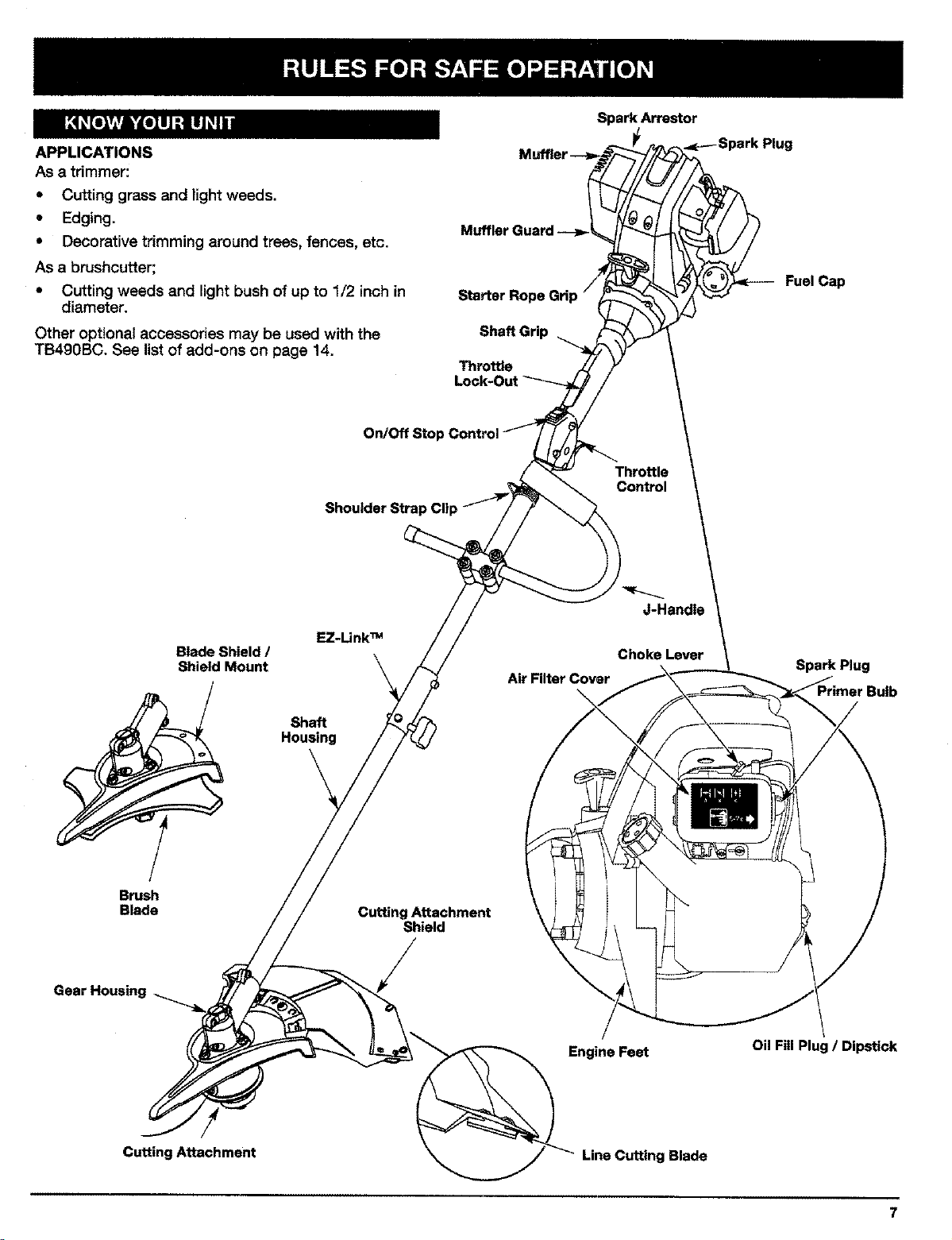
APPLICATIONS
AS a trimmer:
• CuRing gross and light weeds.
• Edging.
• Decorative trimming around trees, fences, etc.
AS a brushcu_er;
• Cutting weeds and light bush of up to 1/2 inch in
diameter.
Other optional accessories may be used with the
TB490BC. See list of add-ons on page 14,
On/Off Stop
Shoulder Strap Clip
Spark Arrestor
•=p---Spark Plug
Muffler Guard -->
Fuel Cap
Starter Rope
Shaft Grip
Throt'de
Throttle
Control
Brush
Blade
Gear Housing
Blade Shield /
Shield Mount
EZ-Unk TM
Shaft
Housing
Cutting Attachment
Shield
/
Air Filter Cover
\
Engine Feet
J-Handle
Choke Lever
Spark Plug
Oil Fill Plug / Dipstick
Cutting Attachment
Line Cuffing Blade
7
Page 8
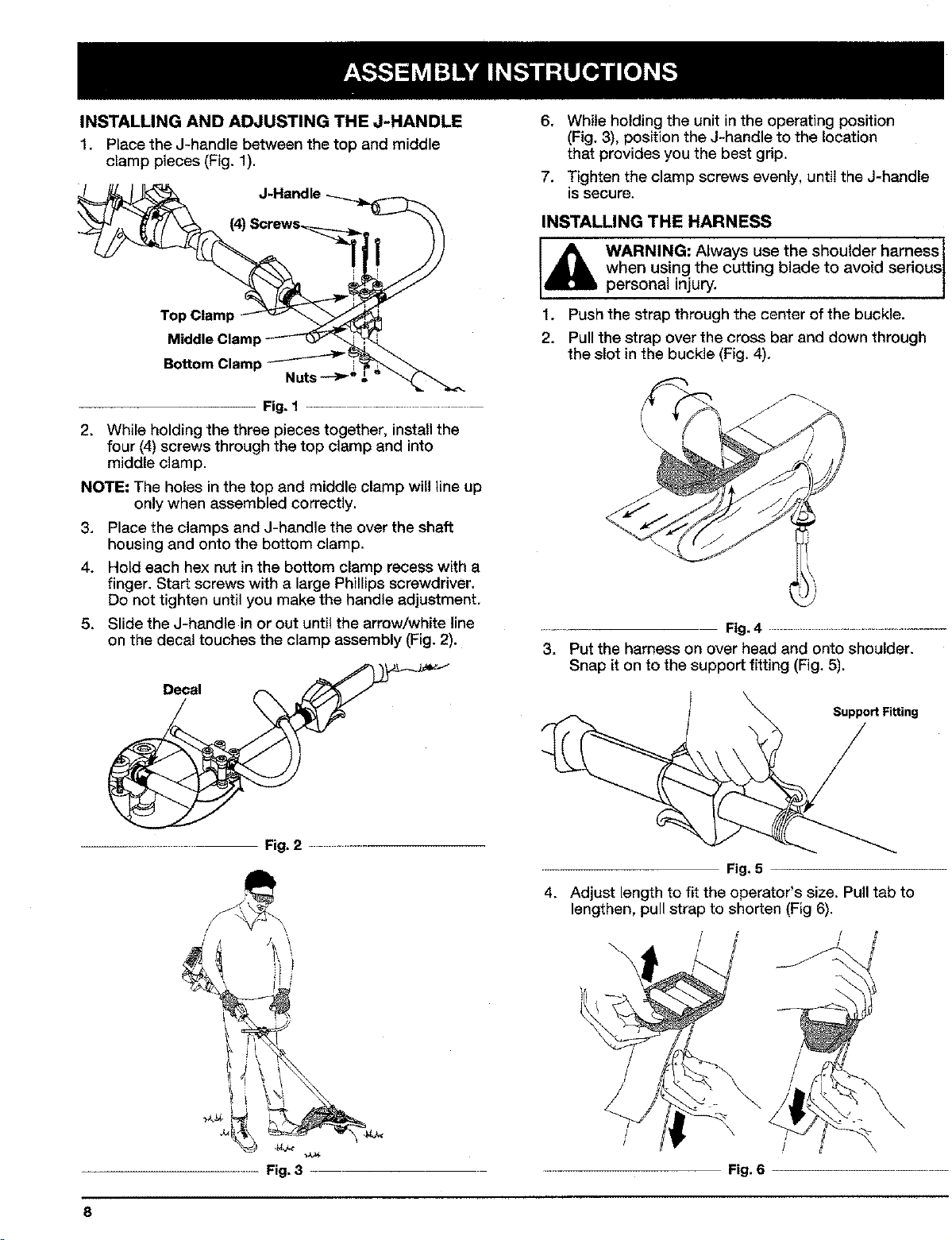
INSTALLINGANDADJUSTINGTHEJ-HANDLE
1. Place the J-handle between the top and middle
clamp pieces (Fig. 1).
J-Handle
(4)
6, While holding the unit in the operating position
(Fig. 3), position the J-handle to the location
that provides you the best grip.
7. Tighten the clamp screws evenly, until the J-handle
is secure.
INSTALLING THE HARNESS
Top Clamp
Middle Clamp
Bottom Clamp
Nuts
Fig, 1 .....................................
2. While holding the three pieces together, install the
four (4) screws through the top clamp and into
middle clamp.
NOTE: The holes in the top and middle clamp will tine up
only when assembled correctly.
3. Place the clamps and J-handle the over the shaft
housing and onto the bottom clamp.
4. Hold each hex nutin the bottom clamp recess with a
finger. Start screws with a large Phillips screwdriver.
Do not tighten until you make the handle adjustment.
5. Slide the J-handle in or out until the arrow/white line
on the decal touches the clamp assembly (Fig. 2).
IA WARNING: Always use the shoulder harness
personalwhenus nginjury.thecutt ng bade to avo d ser cue
1. Push the strap through the center of the buckle.
2. Pull the strap over the cross bar and down through
the slot in the buckle (Fig. 4).
\
\
Fig,4 ................................
3. Put the harness on over head and onto shoulder.
Snap it on to the support fitting (Fig. 5).
Support Fitting
\
S
Fig. 3
Fig, 5
4. Adjust length to fit the operator's size. Pull tab to
lengthen, pull strap to shorten (Fig 6).
#
\
Fig. 6
Page 9
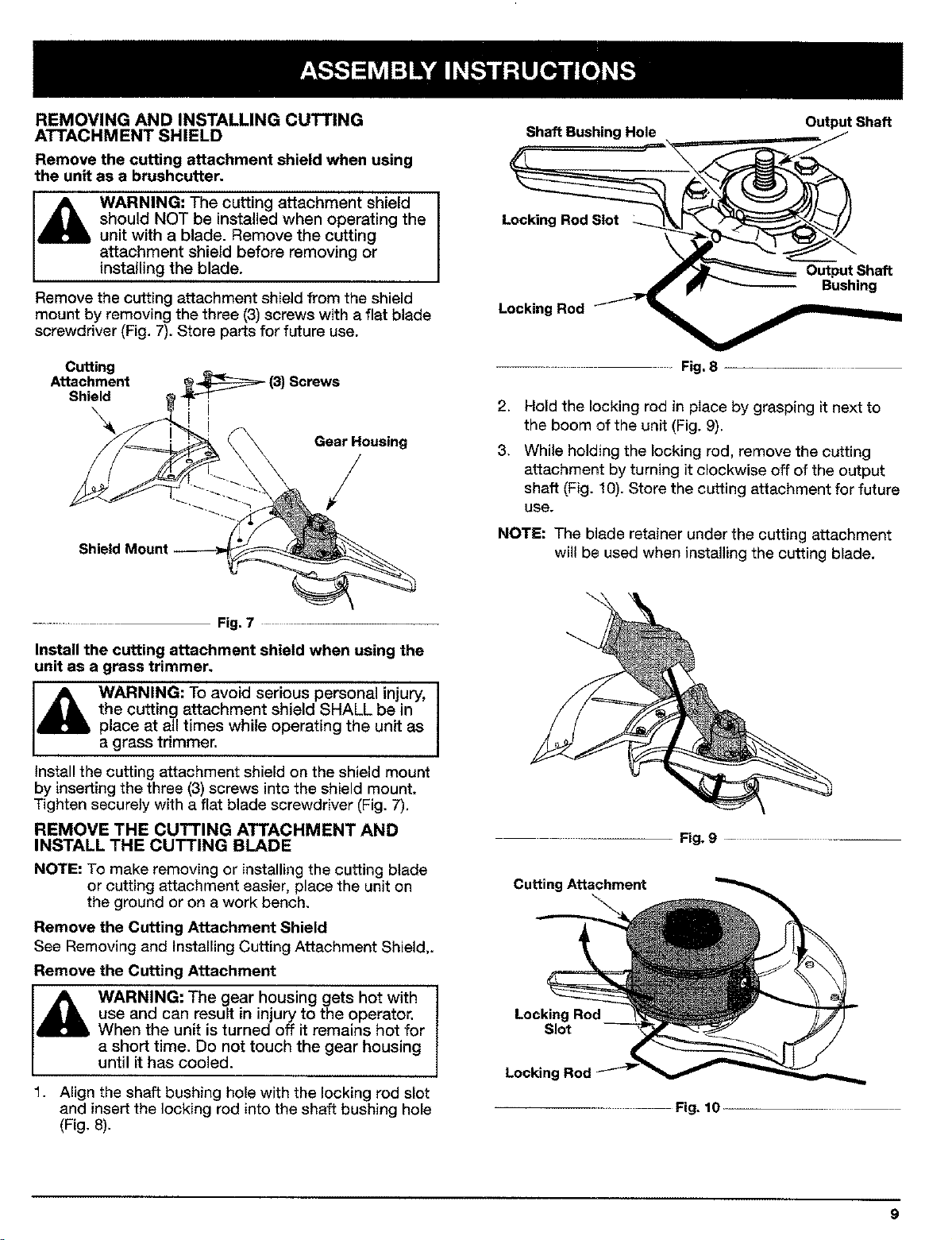
REMOVING AND INSTALLING CUTTING
ATTACHMENT SHIELD
Remove the cutting attachment shield when using
the unit as a brushcutter.
WARNING: The cutting attachment shield I
should NOT be installed when operating the
unit with a blade. Remove the cutting
attachment shield before removing or
installing the blade.
Remove the cutting attachment shield from the shield
mount by removing the three (3) screws with a flat blade
screwdriver (Fig. 7). Store parts for future use.
OutputShaft
I
j OutputSh
• _ | Bushing
Locking Rod i _ _dl_m_mmm.__
Cutting
Attachment
Shield
Shield Mount
............ Fig. 7
Install the cutting attachment shield when using the
unit as a grass trimmer.
WARNING: To avoid serious personal injury,
the cutting attachment shield SHALL be in
place at all times while operating the unit as
a grass trimmer.
Install the cutting attachment shield on the shield mount
by inserting the three (3) screws into the shield mount.
Tighten securely with a flat blade screwdriver (Fig. 7).
REMOVE THE CUTTING ATTACHMENT AND
INSTALL THE CUTTING BLADE
NOTE: To make removing or installing the cutting blade
or cutting attachment easier, place the unit on
the ground or on a work bench.
Remove the Cutting Attachment Shield
See Removing and Installing Cutting Attachment Shield,.
Remove the Cutting Attachment
WARNING: The gear housing gets hot with
use and can result in injury to the operator.
When the unit is turned off it remains hot for
a short time. Do not touch the gear housing
until it has cooled.
1. Align the shaft bushing hole with the locking rod slot
and insert the locking rod into the shaft bushing hole
(Fig. 8).
Screws
Gear Housing
........ Fig, 8
2. Hold the locking rod in place by grasping it next to
the boom of the unit (Fig. 9).
3, While holding the locking rod, remove the cutting
attachment by turning it clockwise off of the output
shaft (Fig. 10). Store the cutting attachment for future
use.
NOTE: The blade retainer under the cutting attachment
wil! be used when installing the cutting blade.
Fig. g .......
Cutting Attachment
Locking Rod
Slot
r
Locking Rod
....... Fig. 10
9
Page 10
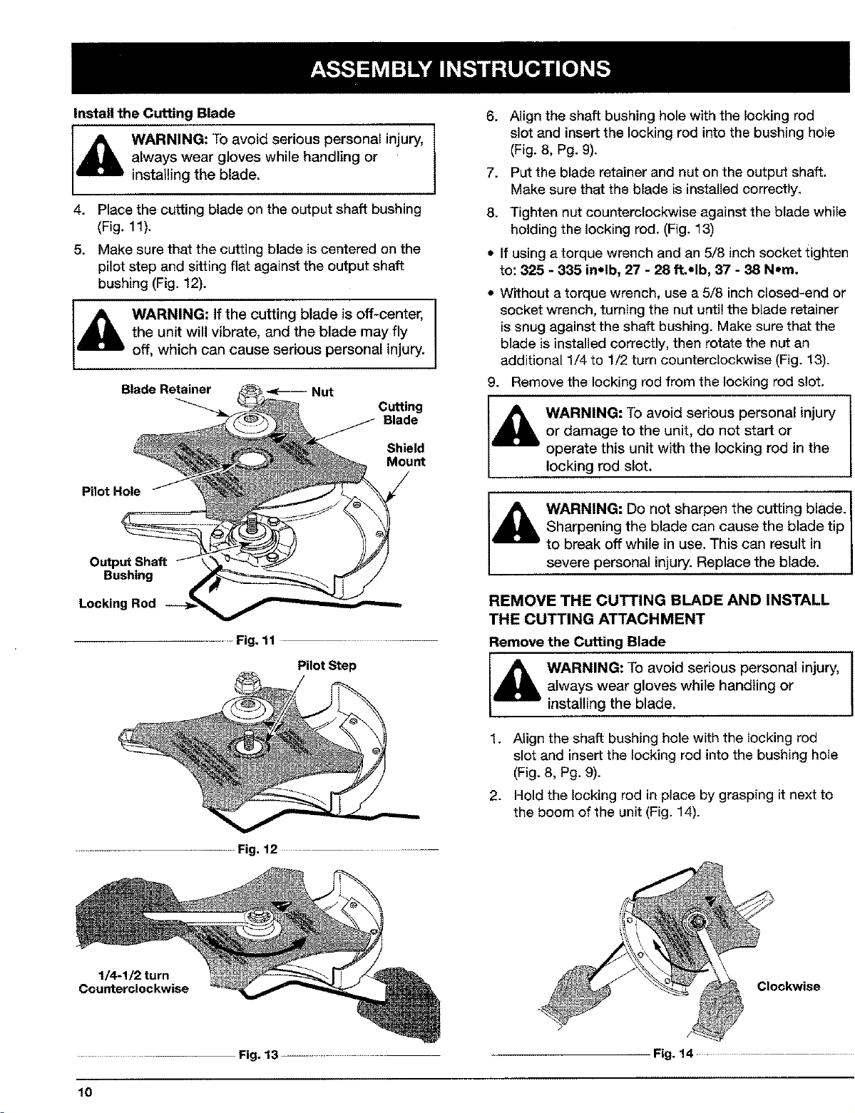
Install the Cutting Blade
WARNING: To avoid serious personal injury,
always wear gloves while handling or
installing the blade.
4. Place the cutting blade on the output shaft bushing
(Fig. 11).
5. Make sure that the cutting blade is centered on the
pilot step and sitting flat against the output shaft
bushing (Fig. 12).
WARNING: If the cutting blade is oft-center,
the unit will vibrate, and the blade may fly
off, which can cause serious personal injury.
Blade Retainer
Pilot Hole
Nut
Cutting
Blade
Shield
Mount
I
6. Align the shaft bushing hole with the locking rod
slot and insert the locking rod into the bushing hole
(Fig. 8, Pg. 9).
7. Put the blade retainer and nut on the output shaft.
Make sure that the blade is installed correctly.
8. Tighten nut counterclockwise against the blade while
holding the locking rod. (Fig. 13)
• If using a torque wrench and an 5/8 inch socket tighten
to: 325 - 335 inolb, 27 - 28 ft.-Ib, 37 - 38 Nora.
• Without a torque wrench, use a 5/8 inch closed-end or
socket wrench, turning the nut until the blade retainer
issnug against the shaft bushing. Make sure that the
blade is installed correctly, then rotate the nut an
additional 1/4 to 1/2 turn counterclockwise (Fig. 13).
9, Remove the locking rod from the locking rod slot.
WARNING: To avoid serious personal injury I
or damage to the unit, do not start or
operate this unit with the locking rod in the
locking rod slot.
I
Output Shaft
Bushing
Locking Rod __--
Fig. 11 .............
Pilot Step
Fig. 12 ..............
Sharpening the blade can cause the blade tip I
l,_ WARNING: Do not sharpen the cutting blade. I
REMOVE THE CUTTING BLADE AND INSTALL
THE CUTTING ATTACHMENT
Remove the Cutting Blade
[,_ ARNING: To avoid serious personal injury,
1, Align the shaft bushing hole with the locking rod
2. Hold the locking rod in place by grasping it next to
to break off while in use. This can result in
severe personal injury. Rep ace the bade.
always wear gloves while handling or
installing the blade.
slot and insert the locking rod into the bushing hole
(Fig, 8, Pg. 9).
the boom of the unit (Fig. 14).
1/4-1/2 turn
Counterclockwise
10
Clockwise
Fig. 13 ...... Fig. !4
Page 11

3. While holding the locking rod, loosen the nut on
the blade by turning it clockwise with a 5/8 inch
closed-end or socket wrench (Fig. 14).
4. Remove the nut, blade retainer, and blade. Store the
nut and blade together for future use in a secure
place. Store out of reach of children.
Install the Cutting Attachment
5. Align the shaft bushing hole with the locking rod slot
and insert the locking rod into the shaft bushing hole.
(Fig. 8, Pg. 9). Place the blade retainer on the output
shaft with the flat surface against the output shaft
bushing as shown in Fig. 15. Screw the cutting
attachment counterclockwise onto the output shaft.
Tighten securely.
NOTE: The blade retainer must be installed on the
output shaft in the position shown for the cutting
attachment to work correctly.
6. Remove the locking rod,
7. Install the cutting attachment shield. See Removing
and Installing Cutting Attachment Shield, Pg. 9.
Cutting Attachment
\
Blade Retainer
Output Shaft
Bushing
Locking Rod
......... Fig. 15 .....
WARNING: To avoid serious personal injury,
the cutting attachment shield SHALL be in
place at all times while operating the unit as
a grass trimmer.
DANGER: OVERFILLING OIL CRANKCASE
MAY CAUSE SERIOUS PERSONAL INJURY!
The importance of checking and maintaining
the proper oil level in the crank case cannot
be overemphasized. Check oil before each
use and change as needed. See Changing
the Oil.
RECOMMENDED OIL TYPE
_ Using the proper type and weight of oil in the
crankcase is extremely important. Check the
oil before each use and change the oil
regularly. Failure to use the correct oil, or
using dirty oil, can cause premature engine wear and
failure.
Use a high-quality SAE 30 weight oil of API (American
Petroleum Institute) service class SF, SG, SH.
ADDING OIL TO CRANKCASE - INITIAL USE
NOTE: This unit is shipped without being filled with oil tn
order to avoid damage to the unit, put oil in the
crankcase before attempting to start unit.
Your unit is supplied with one 3.4 fluid oz. (100 ml.)
bottle of SAE 30 SF, SG, SH oil (Fig. 16).
NOTE: Save the bottle to measure the correct amount
for future oil changes. See Changing the Oil.
1. Unscrew the top of the bottle of oil and remove the
paper seal covering the opening. Replace top. Cut
the tip off the funnel spout (Fig. 16).
2. Place the unit on a flat level surface.
3. Remove the oil plug / dipstick from the crankcase
(Fig. 17).
........ Fig. 16 ........
O-Ring
Oil Fill
Oil Fill Hole
..... Fig, 17 ........
11
Page 12

4. Pour the entire bottle of oil into the oil fill hole
(Fig, 18),
FUELING UNIT
and its vapors can explode if ignited. To
avoid serious personal injury, always stop the
engine and allow it to cool before filling the
I4_ ARNING: Gasoline is extremely flammable
fuel tank. Do not smoke while filling the tank.
Keep sparks and open flames away from the
area.
1. Remove fuel cap (Fig. 19).
J
Oil F
LJ
...... Fig.18 ..........
NOTE: Never add oil to the fuel or fuel tank.
5. Wipe up any oil that may have spilled and reinstall
the oiI fill plug / dipstick.
RECOMMENDED FUEL TYPE
Old fuel is the primary reason for the unit not running
properly. Be sure to use fresh, clean, unleaded Gasoline.
NOTE: This is a four cycle engine. In order to
avoid damage to the unit, do not mix oil with
Gasoline.
Definition of Blended Fuels
Today's fuels are often a blend of gasoline and
oxygenates such as ethanol, methanol or MTBE (ether).
Alcohol-blended fuel absorbs water. As littleas t %
water in the fuel can make fuel and oil separate orform
acids when stored. Use fresh fuel (less than 60 days
old), when using alcohol-blended fuel.
Using Blended Fuels
If you choose to use a blended fuel, or its use is
unavoidable, follow recommended precautions.
• Always use fresh unleaded gasoline
• Use the fuel additive STA-BIL ® or an equivalent.
• Drain tank and run the engine dry before storing unit.
Using Fuel Additives
The use of fuel additives, such as STA-BIL ® Gas
Stabilizer or an equivalent, will inhibit corrosion and
minimize the formation of gum deposits. Using a fuel
additive can keep fueI from forming harmful deposits in
the carburetor for up to six (6) months. Add 0.8 oz.
(23 mL) of fuel additive per gallon of fuel according to the
instructions on the container. NEVER add fuel additives
directly to the unit's gas tank.
_ WARNING: Remove fuel cap slowly to avoid
njury from gaso ne spray.
Gas Can S _r_
FuelCap _ Fuel Tank
Fig. 19 ....
2. Place spout of gas container into the fill hole on the
fuel tank (Fig. 19) and fill tank,
ventilated area outdoors. Avoid creating a
[_lb WARNING: Add gasoline in a clean, well
source of ignition for spilt fuel.
NOTE: Do not overfill tank.
3. Wipe up any gasoline that may have spilled
4. Reinstallthe fuel cap.
WARNING: Never operate the unit without
the fuel cap securely in place.
5. Move the unit at least 30 ft. (9.1 m) from the fueling
source and site before starting the engine.
NOTE: Dispose of the old gasoline in accordance to
Federal, State, and Local regulations.
12
Page 13

STARTING INSTRUCTIONS
Cold Start - First Start of the Day or Engine Ran Out
of Fuel
WARNING: Operate this unit only in a well
ventilated area outdoors. Carbon monoxide
exhaust fumes can be lethal in a confined
area.
1. Check oil level in crankcase. See Checking the Oil
LevelPg. 19.
2. Fill the fuel tank with fresh, clean, unleaded gasoline
(see page 12).
3. Put the Start/Stop Engine Control in the START [I]
position (Fig. 20).
9. PulI the starter rope 1 to 3 pulis until the engine
starts. Run for 15-30 seconds, if the unit fails to start
return to step 7.
10. Move the choke lever to the RUN (C) I{ I position and
run at full throttle for 30 seconds.
WARNING: Avoid accidental starting. Be in I
the starting position whenever pulling the
starting rope. To avoid serious personal
injury, the operator and unit must be in a
stable position while starting.
J
Stop Control
START {1)
....... Fig. 20
4. Place the choke lever in the FULL choke (A) H
position (Fig. 21)•
NOTE: Slide the choke lever directly above the
appropriate symbol on air filter cover decal
(Fig. 2!).
5,
Fully press and release the primer bulb slowly 7
times. Gasoline should be felt and visible in the bulb
(Fig. 21). If gasoline has not entered the bulb, press
three more times, or until it does.
Choke Lever
Primer Bulb
Fig. 21 .......
6. While pressing the throttle lock-out, squeeze the
throttle control to the wide open (full throttle)
position (Fig. 20).
7. With the unit in the starting position (Fig. 21) pull the
starter rope briskly 5 times in the FULL choke (A)H
position. If the engine attempts to run before the
fifth pull, proceed to step 8.
8. Move the choke lever to the PARTIAL (B) I'*'l position
(Fig. 21).
NOTE: The engine will not run in the FULL choke (A)_-I
position.
Starter Rope
Throttle Control
............... Fig,22 .......
11. Release the throttle control to the idle position and
begin operation.
NOTE: If the engine does not start using these
procedures, repeat steps 5 through 11 using
TWO (2) pulls in the FULL choke (A) H position.
Engine Re-Start - Warm Engine With Fuel
1. Put the Start/Stop Engine Control in the START [I]
position (Fig. 20).
2, Move the choke lever to the PARTIAL (B) I*'-Iposition
(Fig. 21).
3, Fully press and release the primer bulb slowly 7
times, Gasoline should be felt and visible in the bulb
(Fig. 21). If gasoline has not entered the bulb, press
three more times, or until it does.
4. While pressing the throttIe lock-out, squeeze the
throttle control to the wide open (full throttle)
position (Fig. 20).
5. With the unit in the starting position (Fig. 22), pull the
starter rope briskly until the engine starts.
6. When the engine starts, move the choke lever to the
RUN (C) I {I position, and run at full throttle for 30
seconds.
NOTE: if the engine does not start using the Engine
Re-start procedures, revert to the Cold Start
procedures.
NOTE: 4-stroke engines, like cars, are able to start in
the idle position. As an alternate method, you
may want to start your unit in the idle position
when the unit is warm. With the Start/Stop
control in the START position, puii the starter
rope briskly. When the engine starts, run at full
throttle for 30 seconds, if the unit fails to start or
dies, revert to the Engine Re-Start procedure.
13
Page 14

STOPPINGINSTRUCTIONS
1. Release your hand from the throttle control (Fig. 22).
Allow the engine to idle.
2. To stop the engine, put the Start!Stop Engine
Control in the STOP [O] position (Fig. 20).
OPERATING THE EZ-LINK TM SYSTEM
The EZ-LInk TM system enables the use of these
optional add-ons.
Blower/Vacuum .......................... BV720r
Cultivator ............................... GC720r
Edger .................................. LE720r
Hedge Trimmer .......................... HS720r
Snow Thrower ........................... ST720r
Straight Shaft Trimmer ..................... SS725r
Sweeper/Blower .......................... SB720r
Tree Pruner .............................. TP720r
Turbo Blower ............................ TB720r
WARNING: Read and understand operator's I
manual for add-on prior to operation.
Removing the Cutting Attachment or Add-Ons:
1. Turn the knob counterclockwise to loosen (Fig. 23).
2. Press and hoId the release button (Fig. 23).
3, While firmly holding the upper shaft housing, pull
the cutting attachment or add-on straight out of the
EZ-LInk TM coupler (Fig, 24).
Installing the Cutting Attachment or Add-Ons:
l_hL ARNING: TO avoid serious personal injury
NOTE: To make installing or removing the add-on easier,
1. Turn knob countercIockwise to loosen (Fig. 23).
and damage to the unit, shut unit off before
removing or installing add-ons.
place the unit on the ground or on a work bench.
EZ-Link TM Coupler
Release Button
I
2. While firmly holding the add-on, push it straight into
the EZ-Link TM coupler (Fig. 24).
NOTE: Aligning the release button with the guide recess
will help instalIation (Fig. 23).
EZ-LinkTM Coupler
"_'_s_ Primary Hole
Release Button
\-
UpperShaft Housing Lower Shaft Housing
........ Fig. 24
3. Turn the knob clockwise to tighten (Fig. 25).
,_ CAUTION: Lock the release button in the I
90°EdgingHole _'-J_
(Trimmer only)'_ \
.... Fig. 25 ........
primary hole and securely tighten the knob
before operating this unit.
Hole
(Trimmer only)
!
L<___Knob
J
CAUTION: The cutting attachment and
add-ons with the EZ-LInk TM system are to be
used in the primary hole unless stated
otherwise in the specific add-ons operator's
manuaI, Using the wrong hole could lead to
personal injury, or damage to the unit.
I
I
14
Guide Recess
.... Fig. 23 .........
Foredging when using the line head cutting attachment
with EZ-Link TM modeIs, lock the release button of the
cutting attachment into the 90° edging hole or the 180 °
edging hole (Fig. 25).
_ll ARNING: Do not use the cutting blade for I
edging or as an edger, severe personal injury
to yourse f or ethers can occur.
I
I
Page 15

HOLDING THE TRIMMER
WARNING: Always wear eye, hearing, foot, I
body protection and strap to reduce the risk
of injury when operating this unit.
Before operating the unit, stand in the operating position
(Fig. 26), Check for the following:
• The operator is wearing eye protection and proper
clothing.
• The right arm is slightly bent, and the hand is holding
the shaft grip.
• The left arm is straight, and the hand is holding the
J-handle,
• The unit is at waist level.
• The cutting attachment is parallel to the ground and
easily contacts the vegetation to be cut without the
operator having to bend over.
........... Fig. 26
ADJUSTING TRIMMING LINE LENGTH
The Bump HeadTM cutting attachment allows you to
release trimming line without stopping the engine. To
release more line, lightly tap the cutting attachment on
the ground (Fig. 27) while operating the trimmer at high
speed.
NOTE: Always keep the trimming line fully extended.
Line release becomes more difficult as cutting
line becomes shorter
\
I
Each time the head is bumped, about 1 inch (25.4 mm,)
of trimming line is released. A blade in the cutting
attachment shield will cut the line to the proper length if
excess line is released.
For best results, tap the Bump Head TM on bare ground
or hard soil. If line release is attempted in tall grass, the
engine may stall. Always keep the trimming line fully
extended. Line release becomes more difficult as the
cutting line becomes shorter.
NOTE: Do not rest the Bump Head TM on the ground
while the unit is running.
CAUTION: Do not remove or alter the line
cutting blade assembly. Excessive line length I
will make the clutch overheat. This may lead I
to serious personal in ury or damage to the
unt.
Some line breakage will occur from:
• Entanglement with foreign matter
• Normal line fatigue
- Attempting to cut thick, stalky weeds
• Forcing the line into objects such as walls or fence
posts
TIPS FOR BEST TRIMMING RESULTS
• Keep the cutting attachment parallel to the ground.
• Do not force the cutting attachment. Allow the tip of
the line to do the cutting, especially along walls.
Cutting with more than the tip will reduce cutting
efficiency and may overload the engine.
• Cut grass over 8 inches (200 mm) by working from
top to bottom in small increments to avoid
premature line wear or engine drag.
• Cut from left to right whenever possible. Cutting to
the right improves the unit's cutting efficiency.
Clippings are thrown away from the operator.
• Slowly move the trimmer into and out of the cutting
area at the desired height. Move either in a forward-
backward or side-to-side motion. Cutting shorter
lengths produces the best results.
• Trim only when grass and weeds are dry.
• The life of your cutting line is dependent upon;
• Following the previous trimming techniques
• What vegetation is being cut
• Where it's being cut
For example, the line will wear faster when trimming
against a foundation wall as opposed to trimming
around a tree.
............. Fig. 27 ...........
15
Page 16

DECORATIVE TRIMMING
Decorative trimming is accomplished by removing all
vegetation around trees, posts, fences, etc.
Rotate the whole unit so that the cutting attachment is at
a 30° angle to the ground (Fig. 28).
........ Fig. 28 ......
USING THE CUTTING BLADE
WARNING: Always wear eye, hearing, foot, I
body protection and the strap to reduce the
WARNING: Do not use the cutting blade for
edging or as an edger, severe personal injury
to yourself or others can occur. I
Before operating the unit with the cutting blade stand in
the operating position (Fig. 29).
Cutting Blade Operating Tips:
To establish a rhythmic cutting procedure:
• Plant feet firmly, comfortably apart.
• Bring the engine to full throttle before entering the
material to be cut. The blade has maximum cutting
power at full throttle and is less likely to bind, stall, or
cause blade thrust, which can result in serious
personal injury to the operator or others.
WARNING: The blade continues to spin after!
the engine is turned off. The coasting blade
can seriously cut you if accidentally touched.
• Swing the unit inthe same direction as the blade
spins, which increases the cutting action.
• Move forward to the next area to be cut after the
return swing and plant feet again.
•' The cutting blade is designed with a second cutting
edge, which can be used by removing the blade,
turning it upside down, and reinstalling it.
WARNING: Do not sharpen the cutting
blade. Sharpening the blade can cause the
blade tip to break off while in use. This can
result in severe personal injury to yourself or
others. Replace the blade.
To reduce the chance of material wrapping around the
blade, follow these steps:
• Cut at full throttle.
• Swing the unit into material to be cut from your right to
your left (Fig. 30).
• Avoid the material just cut as you make the return
Irisk of injury when operating this unit.
swing.
WARNING: De not clear away cut material
with the engine running or blade turning. To
avoid serious personal injury, turn off engine.
Allow the blade to stop before removing
materials wrapped around the blade shaft.
i
WARNING: Blade thrust may occur when the
spinning blade contacts an object that it
does not immediately cut. Blade thrust can
be violent enough to cause the unit and/or
operator to be propelled in any direction, and
possibly lose control of the unit. Blade thrust
can occur without warning if the blade snags,
stalls or binds. This is more likely to occur in
areas where it is difficult to see the material
being cut.
• Cut while swinging the upper part of your body from
right to left.
• Always release the throttle trigger and allow the engine
to return to idle speed when not cutting.
', When done always unsnap unit from harness before
taking harness off.
16
........ Fig. 29
Page 17

NOTE: Some maintenance procedures may require
special tools or skills. If you are unsure about
these procedures take your unit to an authorized
service dealer.
MAINTENANCE SCHEDULE
These required maintenance procedures should be
performed at the frequency stated in the table. They
should also be included as part of any seasonal tune-up.
FREQUENCY MAINTENANCE REQUIRED REFER TO:
Before Starting Engine Fill fuel tank with fresh fuel Page 12
Check oil Page 19
Every 10 Hours Clean and re-oil air filter. Page 21
1st Change at 10 Hours Change oil Page 19
Every 25 Hours there after Change oil Page 19
Every 25 Hours Clean Spark Arrestor Page 24
10 hours on new engine Check rocker arm to valve clearance and adjust as required Page 23
Every 25 Hours Check rocker arm to valve clearance and adjust as required Page 23
Every 25 Hours Check spark plug condition and gap Page 24
LINE INSTALLATION 4. Use a clean cloth to clean the the inner reel, spring,
This section covers both SpIitLine TM and standard single
line installation.
Always use geniune Troy-Bilt TM 0.105 in. (2.667 mm)
replacement line. Line other than specified may make the
engine overheat or fail.
WARNING: Never use metal-reinforced line, I
wire, chain, or rope, etc. These can break off
and become dangerous projectiles.
I
r
5. Check the indexing teeth on the inner reel and outer
WARNING: To prevent serious injury, never
do maintenance or repairs with unit running.
Always do maintenance and repairs on a
cool unit. Disconnect spark plug wire to
ensure the unit will not start.
shaft, and inner surface of the outer spool (Fig. 32).
spool for wear (Fig. 33). If necessary, remove burrs or
replace the reel and spool.
There are two methods to replace the trimming line.
• Wind the inner reel with new line
• Install a prewourtd inner reel
Winding the Existing Inner Reel
1. Hold the outer spool with one hand and unscrew the
Bump Knob clockwise (Fig. 31). Inspect the bolt
inside the bump knob to make sure it moves freely.
Replace the bump knob if damaged.
2. Remove the inner reel from the outer spool (Fig. 31).
3. Remove spring from the inner reel (Fig. 31).
Spring
Inner Reel _-
Bump Knob _
Fig. 31 ..............
Bolt
Fig. 32
Indexing Teeth
- Fig. 33
NOTE: SplitLine TM can only be used with the inner reel
with the slotted holes. Single line can be used on
either type of inner ree!. Use Figure 30 to identify
the inner reel you have.
NOTE: Always use the correct line length when installing
trimming line on the unit. The line may not
release properly if the line istoo long.
17
Page 18

ForUsewithSingle
LineONLY
Slotted _
Holes
Fig. 34
ForUsewithSplitLineTM
or Single Line
Single Line Installation
Go To Step 8 for SplitLine TM Installation
6. Take approximately 30 feet (9.14 m/ of new trimming
line, loop it into two equal lengths, Insert each end of
the line through one of the two holes in the inner reel
(Fig. 35). Pull the line through the inner reel so that
the loop is as small as possible.
/
Fig. 35 .........
7. Wind the lines intight even layers, onto the reel
(Fig. 36). Wind the line in the direction indicated on
the inner reel. Place your index finger between the
two lines to stop the lines from overlapping. Do not
overlap the ends of the line. Proceed to step 11.
Loop
Fig. 37
10. Before winding, split the line back about 6 inches.
11. Wind the line in tight even layers in the direction
indicated on the inner reel.
NOTE: Failure to wind the line in the direction indicated
wilt cause the cutting attachment to operate
incorrectly.
12. Insert the ends of the line into the two holding slots
(Fig. 38).
13. Insert the ends of the line through the eyelets in the
outer spool and place inner reel with spring inside the
outer spool (Fig. 39), Push the inner reel and outer
spool together. While holding the inner reel and outer
spool, grasp the ends and pull firmly to release the
line from the holding slots in the reel.
NOTE: The spring must be assembled on the inner reel
before reassembling the cutting attachment.
14. Hold the inner reel in place and installthe bump knob
by turning counterclockwise, Tighten securely.
Fig. 36 ......
SplitLine TM Installation
8. Take approximately 15 feet (4,57 m) of new trimming
line. Insert one end of the line through one of the two
holes in the inner reel (Fig. 37). Pull the line through
the inner reel until only about 4 inches is left out.
9. Insert the end of the line into the open hole in the
inner reel and pull the linetight to make the loop as
small as possible (Fig. 37).
18
Holding Slots
...... Fig. 38 ......
Fig. 39 .................
Page 19

INSTALLING A PREWOUND REEL
1. Hold the outer spool with one hand and unscrew the
bump knob clockwise (Fig. 15, Pg. 11). Inspect the
bolt inside the bump knob to make sure it moves
freely. Replace the bump knob if damaged.
2. Remove the old inner reel from the outer spool
(Fig. 31),
3. Remove the spring from the old inner reel
(Fig. 31),
4, Place the spring in the new inner reel.
NOTE: The spring must be assembled on the inner reel
before reassembling the cutting attachment.
5. Insert the ends of the line through the eyelets in the
outer spool (Fig. 39, Pg. 18),
6. Place the new inner reel inside the outer spool. Push
the inner reel and outer spool together. While holding
the inner reeI and outer spool, grasp the ends and
pull firmly to release the line from the holding slots in
the spool.
7. Hold the inner reel in place and installthe bump knob
by turning counterclockwise. Tighten securely, Fig, 41
Replacement Parts: plug/dipstick when checking and changing the
See Accessories / Replacement Parts. oil (Fig. 42).
5, Remove the oil fill plug/dipstick and check oil level,
Oil should be up to the top of the dipstick (Fig. 40).
6. If the level is low, add a small amount of oil to the oil
fill hole and recheck (Fig, 41), Repeat until the oil level
reaches the top of the dipstick.
NOTE: Do not overfill the unit.
Oil Fill Hole
NOTE: Make sure the O-ring is in place on the oil fill
CHECKING THE OIL LEVEL I _I_ DANGER: OVERFILLING OIL CRANKCASE
and damage to the unit, always maintain the the proper oil level in the crank case cannot
I_k CAUTION: To prevent extensive engine wear { The importance of checking and maintaining
The importance of checking and maintaining the proper
oil level in the crankcase cannot be overemphasized.
Check oil before each use:
1. Stop engine and allow oit to drain into the crankcase,
2. Place the unit on a flat, level surface to get a proper
3. Keep dirt, grass clippings, etc., cut of the engine.
4. Remove the oil fill plug/dipstick and wipe off oil.
proper oil level in the crankcase, Never be overemphasized, Check oil before each
bottom°perateofthetheUnitdipstick.Withthe 0 eve be ow the theUseOil.andchange as needed. See Changing
oil level reading,
Clean the area around the oil fill plug/dipstick before
removing it.
Reinsert it all the way back in.
I_k MAY CAUSE SERIOUS PERSONAL INJURY!
L
Fig. 42
Full _
Add 1.4-1.5 Oz.
141-44 ml)
Top of Dipstick
Fig. 40
19
Page 20

CHANGING THE OIL
For a new engine, change the oil after the first 10 hours
of operation. Change the oil while the engine is still
warm. The oil will flow freely and carry away more
impurities.
4. Wipe up any oil residue on the unit and clean up any
oil that may have spilled. Dispose of the oil
according to Federal, State and local regulations.
5. Refill the crankcase with 3.4 fluid ounce (100 ml) of
SAE 30 SF, SG, SH oil.
_k AUTION: Wear gloves to prevent injury
1. Unplug spark plug boot to eliminate starting
2. Remove the oil fill plug/dipstick.
3. Pour the oil out of the oil fill hole and into a container
when handling the unit.
by tipping the unit to a vertical position (Fig. 43).
Allow ample time for complete drainage.
I
NOTE: Use the bottle and spout saved from initial use to
measure the correct amount. 3.4 ounce (100 mt)
is approximately to the top of the label on the
bottle (Fig. 44) Check the level with the dipstick.
If the level is low, add a small amount of oil and
recheck (Fig. 40). Do net overfill.
-<-- Fill Level
OW
4-Cycle Motor Oil
i
............. Fig.44
6. Replace the oil fill plug/dipstick.
7. Reconnect spark plug boot.
2O
Page 21

AIR FILTER MAINTENANCE
Cleaning the Air Filter
WARNING: To avoid serious personal injury, t
always turn your trimmer off and allow it to I
cool before you clean or do any maintenance
on it,
Clean and re-oil the air filter every 10 hours of operation,
It is an important item to maintain, Not maintaining the
air filter will VOID the warranty,
1. Open the air filter cover. Push the tab on the right
side of the cover in, pull the air filter cover out and to
the left (Fig. 45),
NOTE: It may be necessary to remove the fuel cap to
completely remove the air filter cover
2. Remove the air filter (Fig, 45).
Choke Lever
Air Filter
Air Filter Cover
Fig,47
5. Squeeze the filter to spread and remove excess oil
(Fig. 48).
Tab
Fig, 45
3. Wash the filter in detergent and water (Fig, 46). Rinse
the filter thoroughly and allow it to dry,
<
Fig. 46 ...............
4, Apply enough clean SAE 30 motor oil to lightly coat
the filter (Fig. 47),
Fig. 48
6. Replace the filter (Fig, 49),
NOTE: If the unit is operated without the air filter, you
will VOID the warranty.
Back Plate
Back Plate Slot
Slots
Fig,49
7. Reinstall the air filter cover. Position the hooks on
the left side of the air filter cover into the slots at the
left side of the back plate (Fig. 49),
NOTE: It may be necessary to remove the fuel cap to
reinstall the air filter cover
8, Swing the cover to the right until the tab on the air
filter cover snaps into place in the slot on the back
plate (Fig. 49).
9. Replace the fuel cap, if removed,
21
Page 22

CARBURETOR ADJUSTMENT
The idle speed of the engine is adjustable. An idle
adjustment screw is reached though a hole in the top of
the engine cover (Fig 50).
NOTE: Careless adjustments can seriously damage your
unit. An authorized service dealer should make
carburetor adjustments.
Check Fuel
Old fuel is usually the main reason for the unit not
running properly. Drain and refill the tank with clean,
fresh unleaded fuel prior to doing any adjustments. Refer
to Oil and Fuel Information.
Clean Air Filter
The condition of the air filter is important to the
operation of the unit. A dirty air filter will restrict air flow
and change the airifueI mixture. This is often mistaken
for an out of adjustment carburetor. Check the condition
of the air filter before adjusting the idle speed screw.
Refer to Air Filter Maintenance.
Adjust Idle Speed Screw
WARNING: The cutting attachment may be
spinning during idle speed adjustment. Wear
protective clothing and observe all safety
instructions to prevent serious personal
injury.
If after checking the fuel and cleaning the air
filter the engine still will not idle, adjust the idle speed
screw as follows.
1. Start the engine and let it run at a high idlefor a
minute to warm up.
2. Release the throttle trigger and let the engine idle. If
the engine stops, insert a small phillips or flat blade
screwdriver into the hole in the engine cover
(Fig. 50). Turn the idle speed screw in, clockwise,
1/8 of a turn at a time (as needed) until the engine
idles smoothly.
NOTE: The cutting attachment should not rotate when
the engine idles.
3. If the cutting attachment rotates when the engine
idles, turn the idle speed screw counterclockwise 1/8
of e turn at a time (as needed), to reduce idle speed.
Checking the fuel, cleaning the air filter, and adjusting
the idle speed screw should solve most engine
problems.
If not and:
• The engine will not idle,
• The engine hesitates or stalls on acceleration,
• There is a loss of engine power,
have the carburetor adjusted by an authorized service
dealer.
WARNING: When the unit is turned off make I
sure the cutting attachment has stopped [
before the unit is set down to prevent serious
persona njury.
ROCKER ARM CLEARANCE
This requires disassembly of the engine. If you feel
unsure or unqualified to perform this, take the unit to an
authorized service center.
NOTE: Inspect the valve to rocker arm clearance with a
feeler gauge after the first 10 hours of operation
and then every 25 hours of operation thereafter.
• The engine must be cold when checking or adjusting
the valve clearance.
• This task shouId be performed inside, in a clean, dust
free area.
1. Remove the muffler cover by pressing down on the
comer with a flat blade screwdriver (Fig. 51). Slide
the notches on the sides of the muffler cover over
the tabs on the engine cover and remove
/
..... Fig.51
2, Remove the two (2) screws on top of the engine cover
with a flathead or T-20 Torx screwdriver (Fig. 52).
22
idle Adjustment Screw
Engine Cover
Top View Of
The Engine
Muffler
Fig. 52
Page 23

3. Remove the screw on back of the engine cover
(Fig. 53).
Rocker Arms
Nuts
Fig. 53
4. Clean dirt from around the spark plug. Remove the
spark plug from the cylinder head by turning a 5/8 in.
socket counterclockwise.
5. Disconnect the spark plug wire.
6. Remove the engine cover.
7. Clean dirt from around the rocker arm cover.
Remove the screw holding the rocker arm cover with
a large flat blade screwdriver or Torx T25 bit
(Fig. 54). Remove the rocker arm cover and gasket.
Rocker Arm Cover
Spark Plug Hole
Fig. 54
8. Pullthe starter rope slowly to bring the piston to the
top of its travel, (known as top dead center). Check
that:
', The piston is at the top of its travel while looking in
the spark plug hole (Fig, 54),
• Both rocker arms move freely, and both valves are
closed.
If not, repeat this step,
9. Slide the feeler gauge between the rocker arm and
the valve return spring. Measure the clearance
between the valve stem and rocker arm (Fig 55),
Do both intake and exhaust valves.
The recommended clearance for both intake and
exhaust is .003- .006 in. (,076- 0.152 mm). Use a
standard automotive .005 in. (0,127 mm) feeler gauge,
The fee_ergauge should sl{de between the rocker arm
and valve stem with a slight amount of resistance,
without binding (Fig. 56),
Feeler Gauge
Gasket
Fig, 55 .............
Adjustinl
Rooker Arm
.003-,006 in.
(,076-0.152 ram)
J
Valve Stem
Fig. 56
10. If the clearance is not within specification:
a. Turn the adjusting nut using a 5/16 inch (8 mm)
wrench or nut driver (Fig. 55).
To increase clearance, turn the adjusting nut
counterclockwise,
• To decrease clearance, turn the adjusting nut
clockwise.
b. Recheck both clearances, and adjust as necessary.
11. Reinstall the rocker arm cover using a new gasket.
Torque the screw to 20-30 in.lb (2.2-3.4 N.m).
NOTE: A rocker arm cover gasket, Part # 182099 can be
purchased from your local authorized dealer.
12. Reinstall the engine cover, Check alignment of the
cover before tightening the screws. Tighten screws.
13. Replace the muffler cover. Slip the long tabs on the
muffler cover into the engine cover. Stide the
notches on the side of the muffler cover over the
tabs on the engine cover and snap into place
(Fig. 51).
14. Check the spark plug and reinstall See Replacing
the Spark Plug,
15. Replace the spark plug wire.
23
Page 24

REPLACING THE SPARK PLUG
Use only Champion RDZ19H spark plug or equivelent. The
correct air gap is 0.025 in. (0.655 mm). Remove the plug
after every 25 hours of operation and check its condition.
1. Stop the engine and allow it to coo]. Grasp the plug
wire firmly and pull the cap from the spark plug.
2. Clean dirt from around the spark plug. Remove
the spark plug from the cylinder head by turning
counterclockwise using a 5/8 inch deep socket.
3. Replace cracked, fouled or dirty spark plug. Set the
air gap at 0.025 in. (0.655 mm) using a feeler gauge
(Fig, 57).
SPARK ARRESTOR MAINTENANCE
1. Remove the muffler cover. See Rocker Arm
Clearance, Pg. 22.
2. With a flat blade screwdriver or Torx T20 bit, remove
the screw attaching the spark arrestor cover to the
muffler (Fig, 56).
Muffler
Spark Arrestor Screen
Tab Screw
Spark Arrestor Cover
Slot
0.025 in.
(0.655 mm.)
Fig.57 ...........
CAUTION: Do notsand blast, scrape, or clean
electrodes. Gdt inthe engine could damage the
cylinder,
4. install a correctly gaped spark plug in the cylinder
head. Tighten by turning the 5/8 inch deep socket
clockwise until snug.
If using a torque wrench torque to;
110-120 in.olb. (12.3-13.5 N*m).
Do not over tighten.
........... Fig.58 .................................
3. Pull the tab on the spark arrestor cover out of the
muffler. Remove the spark arrestor cover.
4. Remove the spark arrestor screen from the spark
arrestor cover.
5. Clean the spark arrestor screen with a wire brush, or
replace.
6. Reinstall the spark arrestor screen, spark arrestor
cover, and screw.
ACCESSORIES/REPLACEMENT PARTS
4-Cycle Oil ......................... 753-1249
Oil Fill Plug / Dipstick ................. 791-182378
Spark Plug ......................... 791-180852B
Spark Arrestor Screen ................ 791-180890
Replacement Line ............... 0.105in (2,667mm)
Replacement Line Cartridge ........... 753-1160
Inner Reel Spring .................... 791-610636B
Outer Spool ........................ 791-683301
Inner Reel .......................... 791-147495
Bump Knob TM ...................... 791-!80814B
Fuel Cap .......................... 791-181083
Shoulder Harness ................... 791-682075B
24
These replacement parts can be purchased from your
local authorized dealer or by calling 1-330-558-7220 or
1-866-840-6483.
Page 25

CLEANING
WARNING: To avoid serious personal injury,
always turn your trimmer off and allow it to
cool before you clean or do any maintenance
on it.
Use a small brush to clean off the outside of the unit. Do
not use strong detergents. Household cleaners that
contain aromatic oils such as pine and lemon, and such
as kerosene, can damage plastic housing or handle.
Wipe off any moisture with a soft cloth.
STORAGE
• Never store the unit with gasoline in the tank where
fumes may reach an open flame or spark.
• Allow the engine to cool before storing.
• Store the unit locked up to prevent unauthorized use
or damage.
• Store the unit in a dry, well ventilated area.
• Store the unit out of the reach of children.
Store the unit in one of three (3) positions:
1. The unit hanging by the cutting attachment end.
2, The unit hanging by the engine.
3. The unit setting upright on the cutting attachment
shield and engine feet.
LONG TERM STORAGE
If the unit wilBbe stored for an extended time,
1. Drain all gasoline from the gas tank into a container.
Do not use gas that has been stored for more than
60 days. Dispose of the old gasoline in accordance
with Federal, State, and Local regulations.
2. Start the engine and allow it to run until it stalls. This
ensures that all gasoline has been drained from the
carburetor.
3.
Allow the engine to cool. Remove the spark plug and
put 1 oz. (30 ml) of high quality motor oil into the
cylinder. Pull the starter rope slowly to distribute the
oil. Reinstall the spark plug.
NOTE: Remove the spark plug and drain all of the oil
from the cylinder before attempting to start the
trimmer after storage.
4. Change the oil. See Changing the Oi!. Dispose of
the old oil in accordance with Federal, State, and
Local regulations.
5. Thoroughly clean the unit and inspect for any loose
or damaged parts. Repair or replace damaged parts
and tighten loose screws, nuts or bolts. The unit is
ready for storage.
TRANSPORTING
• Allow the engine to cool before transporting.
• Secure the unit while transporting.
• Drain the gas tank before transporting.
• Tighten gas cap before transporting.
25
Page 26

CAUSE
IgnitionswitchisOFF
Empty fuel tank
Primer bulb wasn't pressed enough
Engine flooded
Old Gasoline
Fouled spark plug
ACTION
Turn switch to ON
FillfueI tank
Press primer bulb fully and slowly 5-7 times
Use starting procedure with choke lever in the
RUN position, Pg+13
Drain fuel tank/Add fresh Gasoline
Replace or clean the spark plug
CAUSE
Air Filter is Plugged
Old Gasoline
improper carburetor adjustment
CAUSE
Old Gasoline
improper carburetor adjustment
Cutting head bound with grass
Dirty air filter
Clogged Spark Arrestor Screen
CAUSE
Old Gasoline
improper carburetor adjustment
Clogged Spark Arrestor Screen
ACTION
Replace or clean the air filter
Drain fuel tank / Add fresh Gasoline
Adjust per instruction Pg. 22
ACTION
Drain gas tank / Add fresh Gasoline
Take to an authorized service dealer for
carburetor adjustment
Stop the engine and clean the cutting attachment
Clean or replace the air filter
Clean or Replace. See Pg. 24
ACTION
Drain fuel tank / Add fresh Gasoline
Take to an authorized service dealer for
carburetor adjustment
Clean or Replace. See Pg. 24
CAUSE
Cutting head bound with grass
Cutting head out of line
Inner reel bound up
Cutting head dirty
Line welded
Line twisted when refilled
Not enough line is exposed
if further assistance is required, contact your authorized service dealer.
26
ACTION
Stop the engine and clean cutting attachment
Refill with new line
Replace the inner reel
Clean inner reel and outer spool
Disassemble, remove the welded section
and rewind the line
Disassemble and rewind the line
Push the Bump Knob and pull out line until
4 inches (102 mm) of line is outside of the
cutting attachment
Page 27

Engine Type ................................................................. Air-Cooled, 4-Cycle
Displacement ................................................................. 1.6 cu. in. (26.2 cc)
Clutch Type ......................................................................... Centrifugal
Operating RPM (Trimmer) ......................................................... 7,200-8,300 rpm
Operating RPM (Brushcutter) ...................................................... 7,200-9,800 rpm
Idle Speed RPM ................................................................. 3,000-3,600 rpm
Ignition Type ......................................................................... Electronic
Ignition Switch .................................................................... Rocker Switch
Valve clearance (intake and exhaust) ...................................... 003-.006 in. (.076-.0152 mm)
Spark Plug Gap ............................................................ 0.025 inch (0.655 mm)
Lubrication .......................................................................... SAE 30 Oil
Crankcase Oil Capacity ............................................................ 3.4 oz (100 ml)
Fuel ................................................................................ Unleaded
Carburetor ................................................................ Diaphragm, All-Position
Starter ............................................................................ Auto Rewind
Muffler ....................................................................... Baffled with Guard
Throttle .................................................................... Manual Spring Return
Fuel Tank Capacity ................................................................. 20 oz (591 ml)
Fuel Tank ....................................................................... HD Polyethylene
Drive Shaft Housing ...................................................... Aluminum Tube (EZ-Link TM)
Throttle Control ................................................................. Finger-Tip Trigger
Unit Weight (No Fuel, with J-handle, Cutting attachment shield and Cutting attachment) ....... 13.5 Ibs (6.13 kg)
Cutting Mechanism ..................................... 4-Tooth Cutting Blade, Dual String Cutting Head
Line Spool ................................................................... Bump Line Releaser
Line Spool Diameter .......................................................... 4 inches (101.6 mm)
Trimming Line Diameter ....................................................... 0.105 inch (2.66 ram)
Cutting Path Diameter, Cutting Attachment ......................................... 18 inches (45.7 cm)
Cutting Path Diameter, Cutting Blade ............................................... 8 Inches (204 ram)
Shoulder Harness .............................................................. Single Quick-Snap
27
Page 28

ENGINE PARTS - MODEL TB490BC
4-CYCLE GAS TRIMMER
(ppn - 41ADT49C063) (Serial Number 011 ...... and greater)
Part Numbers On Following Page
22B
%
/
@
28 Reissued12/01
Page 29

ENGINE PARTS - MODEL TB490BC
4-CYCLE GAS TRIMMER
(ppn - 41ADT49C063) (Serial Number 011 ...... and greater)
!_m Part_Lo_
1 79!-182338
2 791-182339
3 791-!8!925
4 791-!82098
5 791-182099
8 791-182340
7 791-182101
8 791-182100
9 791-!82341
10 791-182103
11 791-181038
12 791-182102
13 791-181033
14 791-182700
15 791-182344
16 791-182345
17 791-182749
18 791-181034
19 791-182347
20 791-182348
21 791-182732
22A 791-182654
22B 753-1225
23 791-181751
24 753-1227
25 791-182097
26 791-181750
27 791-181757
28 753-1228
29 753-1229
30 791-182352
31 791-182353
32 791-181080
33 791-182354
34 753-1230
35 791-182356
36A 753-1234
36B 753-1231
37 791-182358
38 791-181045
39 791-182359
40 791-180890
41 791-181845
42 791-181046
43 791-182360
44 791-182361
45 791-182362
46 791-182804
Engine Cover
Engine Cover Screws
Valve Cover Screw
Valve Cover
Valve Cover Gasket
Rocker Adjustment Nut
Rocker Arm Pivot
Rocker Arm
Rocker Arm Stud
Valve Spring Retainer
Valve Spring
Push Rod Guide
Push Rod
Cylinder Head (includes 9 & 12)
Cylinder Screw
intake Baffle
Carburetor Mount Gasket
Nut
Carburetor Mount (includes t8)
Carburetor Mount Screw
Carburetor Gasket
Carburetor with Primer
Carburetor with Primer
O-Ring, Carburetor
Air Filter/Choke Cover Assembly
(includes 27 & 28)
Breather Tube
Air Filter Mounting Screw
Air Filter
Air Filter Cover
FueI Cap
Fuel Return Line
FueI Pick-Up Line with Filter
Screw
Washer
Fuel Tank Assembly (includes 29-31)
Fuel Tank Shield
Throttle Cable
Throttle Cable
Muffler Baffle
Muffler Gasket
Muffler (includes 40, 42-44)
Spark Arrestor Screen
Screen Cover
Screw
Muffler Shield
Muffler Mounting Screw
Muffler Cover
Switch Wire Assembly
IJ,_m _:t _L_.
47 791-18t247 Painut
48 753-1199 Recoil Pulley
49 791-613102 Recoil Spring
50 791-182366 Nut Clip
51 791-181079 Pull Handle
52 791-611061 Rope Guide
53 791-613103 Rope
54 791-181020 Starter Housing Screw
55 753-1237 Starter Housing Assembly
(includes 49-56)
55 791-182368 Clutch Washer
57 753-1238 C_utch with Spacer
58 791-153592 Clutch Drum
59 753-1239 Clutch Cover
60 791-145569 Anti-Rotation Screw
61 753-1240 Screw
82 753-1241 Nut
63 791-181345 Clutch Cover Screw
64 79!-182725 Ignition Module with Screws
65 791-181065 Spacer
66 791-181867 Flywheel
67 791-182743 Shroud Assembly with Screws
68 753-1244 Crankcase Assembly
(includes 69-73)
69 791-610309 Oil Seal
70 791-!82372 Bearing
71 791-182380 Crankshaff
72 791-182375 90 ° EIbow
73 791-182379 Breather Hose
74 791-181015 Cam Gear
75 753-1242 Cam Fo!_ower Set
76 791-181013 Cam Bracket
77 791-181012 Cam Bracket Screw
78 791-181040 Valves, Intake and Exhaust
79 791-182374 Cylinder Gasket
80 791-181018 Oi_Pan Gasket
81 791-182377 Oil Pan (incIudes 80 & 82)
82 791-181020 Oil Pan Screw
83 791-182378 Dipstick Assembly (includes 84)
84 791-182290 O-Ring
85 791-181009 Connecting Rod
86 791-181008 Wdst Pin Bu_on
87 753-1243 Piston
88 791-181006 Wnst Pin
89 791-182295 Piston Ring Set
90 791-182409 Washer
91 791-181851 Screw
92 791-612468 Compression Spnng
93 791 -I 82537 Grommet
791-180852B Spark P_ug
753-1245 Short Block Assembly
(includes 3-7, 68-89)
791-182745 Cylinder Assembly
(includes 9, 12, 14 & 79)
791-180142 Starter Pawl Repair Kit
791-182156 Carburetor Repair Kit
753-1248 Gasket Diaphragm Repair Kit
Parts not shown
Reissued 12/01 29
Page 30

BOOM AND TRIMMER PARTS - MODEL
TB490BC
4-CYCLE GAS TRIMMER
®(
1 791-00040
2 791-00041
3 791-00042
4 791-182690
5 791-182673
6 791-6!0327
7 753-1247
8 79!-!81099
9 791-612831
10 79t-612021
11 791-683296
12 791-181811
13 791-181812
14 791-181813
15 791-181814
16 791-181815
17 791-145569
18 753_1190
19 791-182057
20 791-181617
21 791-181981
22 791-181886
23 791-182541
24 791-613300
25 791-182200
26 791-182193
27 791-182195
28 791-145569
29 791-147492
30 791-182196
31 791-683304
32 753-1191
33 791-68206I
34 791-147490
35 791-612483
36 791-683301
37 791-612026
38 791-610636B
39 791-147495
40 791-180814B
41 791-145873B
42 791-181699
791-180014B
791-613226
791-682075B
Descrij_tion
Throttle Housing and Tdgger
Assembly (includes 2-4) (_'
Throttle Trigger Lock-Out _Throttle Trigger
Throttle Trigger Spring
Switch Assembly
Harness Clip
Upper Drive Shaft Housing Assembly
J-Handle Assembly (includes 9 & 1(3)
Grip
Tube Closure
Handle Bracket Assembly (includes 12-!7)
Screw
Upper Handle Clamp
Middle Handle Clamp
Lower Handle Clamp
Nut
Anti-Rotation Screw
Click-Link Coupler (includes 18-22)
Screw
Bott
Adjustment Knob
Knob Retaining Nut
Lower Drive Shaft Housing Assembly
Lower Flexible Drive Shaft
Shield Mount Screw Assembly
2 piece Gearbox Assembly
(includes 25, 97 & 28)
Gearbox Screw
Anti-Rotation Screw
Blade Shield/Shield Mount
Blade Driver
Shield Mounting Screw
Shield and Blade Assembly (includes 33)
Blade Assembly
Retaining Washer
Spool Shaft
Outer Spool and
Eyelet Assembly
Retainer
Spring
Inner Reel
Bump Head Knob Assembly
4-Tooth Blade
Nut
Blade Retaining Kit
(includes 34 & 42)
Locking Rod Tool
_Shoulder Harness
2 Pjec_e Gearbox Assembly Parts - IJLe_ _ __
43 791-182191 Left Housing _ _ )_
44 791-182192 Right Housing __
45 791-182194 Pinion Gear Assembty _ _
46 791-182199 Output Shaft Bushing
47 791-182198 Output Shaft Gear
46 791-182197 Output Shaft Assembly
49 753-1159 O-Ring
_ptional Accessories
753-1160 Reel and Line Assembly
753-1161 Bump Head Assembly
753_1249 4-Cycle Oil
@
[J
(includes 46 & 47)
(includes 35-40)
Items Not Shown
30 Reissued 12/01
Page 31

31
Page 32

MANUFACTURER'S LIMITED WARRANTY FOR:
O _ +glIIIIIIL _ ,llmllllV _mmm
The limited warranty set forth below is given by Troy-Bilt
LLC with respect to new merchandise purchased and
used in the United States, its possessions and territories.
Troy-Bilt LLC warrants this product against defects in
material and workmanship for a period of two (2) years
commencing on the date of original purchase and will, at
its option, repair or replace, free of charge, any part found
to be defective in material or workmanship. This limited
warranty shall only apply if this product has been operated
and maintained in accordance with the Operator's Manual
furnished with the product, and has not been subject to
misuse, abuse, commercial use, neglect, accident,
improper maintenance, alteration, vandalism, theft, fire,
water or damage because of other peril or natural disaster.
Damage resulting from the installation or use of any
accessory or attachment not approved by Troy-Bilt LLC
for use with the product(s) covered by this manual will void
your warranty as to any resulting damage. This warranty is
limited to ninety (90) days from the date of original retail
purchase for any Troy-BUt product that is used for rental or
commercial purposes, or any other income-producing
purpose.
HOW TO OBTAIN SERVICE." Warranty service is
available, WITH PROOF OF PURCHASE THROUGH
YOUR LOCAL AUTHORIZED SERVICE DEALER. To
locate the dealer in your area, visit our website at
www.troybiit.com, check for a listing in the Yellow Pages,
call 1 (866) 840-6483 or 1 (330) 558-7220 or write to P.O.
Box 361131, Cleveland, OH 44136-0019.
This limited warranty does not provide coverage in
the following cases:
A. Tune-ups - Spark Plugs, Carburetor Adjustments,
Filters
TRO RILT °
entity, including a dealer or retailer, with respect to
any product shall bind Troy-Bilt LLC During the period
of the Warranty, the exclusive remedy is repair or
replacement of the product as set forth above. (Some
states do not allow limitations on how long an implied
warranty lasts, so the above limitation may not apply to
you.)
The provisions as set forth in this Warranty provide
the sole and exclusive remedy arising from the sales.
Troy-Bilt LLC shall not be liable for incidental or
consequential loss or damages including, without
limitation, expenses incurred for substitute or
replacement lawn care services, for transportation or
for related expenses, or for rental expenses to
temporarily replace a warranted product. (Some states
do not allow limitationson how long an implied warranty
lasts, so the above limitation may not apply to you.)
In no event shall recovery of any kind be greater than the
amount of the purchase price of the product sold.
Alteration of the safety features of the product shall void
this Warranty. You assume the risk and liability for loss,
damage, or injury to you and your property and/or to
others and their property arising out of the use or misuse
or inability to use the product.
This limited warranty shall not extend to anyone other
than the original purchaser, original lessee or the person
for whom it was purchased as a gift.
How State Law Relates to this Warranty: This warranty
gives you specific legal rights, and you may also have
other rightswhich vary from state to state.
To locate your nearest service deaier dial
1 (877) 282-8684
B. Wear items - Bump Knobs, Outer Spools, Cutting
Line, Inner Reels, Starter Pulley,Starter Ropes, Drive
Belts
C. Troy-Bilt LLC does not extend any warranty for
products sold or exported outside of the United
States of America, its possessions and territories,
except those sold through Troy-Bilt's authorized
channels of export distribution.
Trey-Bilt LLC reserves the right to change or improve the
design of any Troy-Bilt Product without assuming any
obligation to modify any product previously
manufactured.
No implied warranty, including any implied warranty
of merchantability or fitness for a particular purpose,
applies after the applicable period of express written
warranty above as to the parts as identified. No other
express warranty or guaranty, whether written or oral,
except as mentioned above, given by any person or
32
Troy-Bilt LLC
P.O. Box 361131
Cleveland, OH 44136-0019
 Loading...