

Troy-Bilt 34020C, 34022C, 34322C, 34311, 34328 Owner's/operator's Manual
...
iiiiili
ii_ii!i_i_!i!iiiiiiii!i_iii_i_i;;iiiii!iiiiiiiiiiiiiiiii_i_!i!iiii!ii;iiii
.........................!!ii_ili
...._i_'_i_i_ii!ii_!i!iiiiiiiiii;!ii¸¸¸
ili!i;iiiiiiiii!!Liiiiiii!ii!ii!_iiiii!_iii_!_¸
ii!iiiiiii_i!iiiiili!iii!i!ii!!ii!ii!!!ii!iiiiii_,...........
:!iii_iiii)i!_iii_iiiiiiiiiiiiiiii!!iliiiiiiiiiiiiiii!!iiiii!iiii!iii
!i_iliiiiiiii_iiiiiiiiiiiii!ii!iiii!iiii_iiiiilili!iiiiiiii!_iiiii_z_
!ii!!ii_!!iiiiiii_iii_iiiii!iii_ii_iii_i_iiiiiiiiiiiii!iii!_iiiiii_i¢_i_i_i;
Dear Owner:
You now own one of the finest
mulching mowers. Your new mower
provides superior mowing performance
because of a multi-pitch blade, deep
dome-shaped deck, and single-lever
adjustment of cutting height. The self-
propelled units have front wheel drive for
easier handling. All models have
comfortable, easy-to-use controls, and
extra wide radial tires for superior traction.
Please carefully read this Manual which
tells you how to safely and easily unpack,
operate, and maintain your mower.
Be sure that you or any other user care-
fully follows the recommended safely
practices at all times. Failure to do so
could result in personal injury or property
damage.
Of course, if you should ever have any
problems or questions, or for a free
replacement copy of this Manual, please
call us Toll-Free. Our telephone numbers
are listed on the Page 2 and on the back
cover of this Manual.
Please remember, we want to make sure
that you are completely satisfied at all
times.
This product is certified to comply with ANSI
Standard B71.1-1990. All products in this
manual meet the latest CPSC blade safety
requirements.
TROY-BILTFACTORY
DIRECT30-DAY TRIAL
iii!!!iiiiiiiiiiiiiiii!iii!iiii_!ii
i!ii_iiiiiiiiii_iiiil
WARNING:
SERVICE INFORMATION ......................................... 2
SECTION 1: SAFETY.............................................. 3
Training...............................................................................................3
Preparation..........................................................................................3
Operation.............................................................................................4
Maintenanceand Storage....................................................................5
Decals..................................................................................................6
SECTION2: ASSEMBLY.......................................... 7
SECTION3: FEATURESAND CONTROLS...................... 9
Featuresand Controls Identification ....................................................9
All Models.......................................................................................... 10
Models 34020, 34020C,34320 and 34320C(Push Model)...............11
Models 34021, 34021C,34321 and 34321C(Single Speed).............12
Models 34022, 34022C,34322 and 34322C (VariableSpeed)..........13
Models 34023, 34323 and 34323C(Variable Speed/ElectricStart)...14
Models 34311, 34313 and 34328
(Variable Speed/BladeBrakeControl)...........................................15
SECTION4: OPERATION ....................................... 16
Pre-Start Checklist.............................................................................16
FillFuelTank......................................................................................17
Adjust Cutting Height.........................................................................17
Adjust HandlebarPosition .................................................................18
Safety Interlock System.....................................................................18
Models 34020, 34020C, 34320 and34320C (Push Model)...............19
Models 34021,34021C, 34321 and 34321C (Single Speed).............20
Models 34022, 34022C, 34322 and34322C (VariableSpeed)..........21
Models 34023, 34323 and 34323C (VariableSpeed/ElectricStart)...23
Models 34311, 34313 and 34328
(VariableSpeed/BladeBrake Controls) .........................................25
Mowing Tips...................................................................................... 27
Using the OptionalGrass Catcher......................................................28
SECTION 5: MAINTENANCE/REPAIRS........................ 29
Required MaintenanceSchedule (AllModels) ...................................29
WheelSpeedAdjustment (Models 34021, 34021C, 34321
and 34321C) .................................................................................30
WheelTraction Adjustment (All Models ExceptPushModel) ............31
WheelDrive BeltReplacement(All Models Except Models 34311,
34313 and 34328) ........................................................................34
WheelDrive Belt Replacement(Models 34311 and 34328)...............35
BladeMaintenance (ExceptModels 34311, 34313 and 34328).........38
BladeMaintenance (Models34311, 34313 and 34328) ....................38
BladeSharpening and Balancing ......................................................39
CleaningUnderDeck and Under Mower Cover..................................39
OperatorPresenceControls Test (ExceptModels 34311,
34313 and 34328) ........................................................................40
BladeBrakeControls Test (Models34311, 34313 and 34328)..........40
BatteryCharging (Electric Start Models) ...........................................41
EngineMaintenance(All Models) ......................................................42
Off-SeasonStorage (All Models) .......................................................42
Troubleshooting (All Models) ............................................................43
INDEX ........................................................... 45
WARRANTY ........................................... Back Cover
If you have any
Questions or
Problems...
...Please contact your local Mulching Mower authorized
dealer or call or write the Factory. When calling or writing,
please be sure to provide the Model and Serial Numbers of
your machine (refer to Page 1).
IF YOU NEEDENGINE
SERVICE:
If your engine should ever require
service, repair, or
parts, contact ,-=_"=''"_
your nearest
authorized
engine ser- i................................../
vice dealer.
To find the name of
your nearest authorized engine
service dealer, look in the Yellow
Pages of the telephone book under
"Engines-Gasoline." Call us if
you need assistance in obtaining
engine service or parts.
Please remember that your
engine is covered by the engine
manufacturer's Limited Warranty.
Any unauthorized work performed
on the engine during the warranty
period may void the warranty. For
full details on the engine manufac-
turer's Limited Warranty, refer to
the separate Engine Owner's
Manual.
IF YOUNEEDPARTS:
Factory specified replace-
ment parts for your machine
(other then engine parts) are
available from either your
Mulching Mower authorized
dealer or directly from
the Factory.
To order a part, refer
to your separate Parts
Catalog to find the part
number, description, and quantity
of the part you need. Then, con-
>tact your authorized dealer or call
or write our Parts Department
_t the Factory, being sure to
provide the Model and Serial
Numbers of your machine.
Our trained parts
_ specialists will gladly assist
you if you have any difficulty
in identifying the exact part that
you need.
WARNINGTO ALLCALIFORNIA
'_ ANDOTHERPOWEREQUIPMENTOPERATORS
Under California law, and under the laws of several other states,
you are not permitted to operate an internal combustion engine
using hydrocarbon fuels on any forest covered, brush cov-
ered, or grass covered land, or on land covered with grain,
hay, or other flammable agricultural crop, without an
engine spark arrester in continuous effective working order.
The engine on your power equipment, like most outdoor power equipment, is an
internal combustion engine that burns gasoline, a hydrocarbon fuel. Therefore,
your power equipment must be equipped with a spark arrester muffler in continu-
ous effective working order. The spark arrester must be attached to the engine
exhaust system in such a manner that flames or heat from the system will not
ignite flammable material. Failure of the owner/operator of the equipment to com-
ply with this regulation is a misdemeanor under California law, and may also be a
violation of other state and/or federal regulations, laws, ordinances, or codes.
Contact your local fire marshal or forest service for specific information about
what regulations apply in your area. Contact your authorized engine dealer for
information about obtaining a spark arrester.
TRAINING PREPARATION
1. Read this Owner/Operator
Manual and the separate Engine
Owner's Manual carefully before
operating this equipment. Be com-
pletely familiar with the controls
and the proper use of this
equipment.
2. Never allow children or
untrained adults to operate this
equipment.
3. Keep the area of operation clear
of all persons, particularly small
children, and pets. Keep by-
standers at least 25 feet away from
the area of operation.
l. Thoroughly inspect the area
where the mower is to be used.
Remove all stones, sticks, wires,
bones, nails, and other foreign
objects before mowing.
2. Do not operate the mower
when barefoot or wearing open
sandals. Always wear substantial
footwear which will protect your
feet and improve traction.
3. Make sure that the Wheel Drive
Lever (self-propelled models ex-
cept Models 34311 and 34328) is
in the DISENGAGE
position before starting the engine.
4. Never attempt to make a
cutting height adjustment while
the engine is running.
g. Do not operate this equipment
if you are under the influence of
alcohol, medication, or when tired
or ill.
6. Check the fuel before starting
the engine. Do not fill the gaso-
line tank indoors, when the engine
is running, or until the engine has
been allowed to cool for several
minutes after running. The gas
cai5 shall never be removed nor
fuel added while the engine is run-
ning. Clean off any spilled gaso-
line before starting the engine.
7. Mow only in daylight or in
good artificial light.
8. Never operate this mower in
wet grass. Always be sure of your
footing; keep a firm hold on the
handle and walk, never run.
9. Never operate the mower with-
out guards and all safety devices
in place.
10. Never attempt to disconnect
any safety devices or to defeat the
purpose of these safety devices.
11. Gasoline is highly flammable
and its vapors are explosive.
Handle gasoline with extreme
care. Use an approved fuel con-
tainer.
12. Keep smoking materials,
sparks, or flame away from the
fuel tank and fuel container.
13. Move the mower away from
any gasoline fumes before starting
the engine.
14. Batteries (on electric start
model) produce explosive gases.
Keep sparks, flame, or cigarettes
away. Ventilate the area when
charging the battery.
15. Do not charge the battery
(electric start model) in an airtight
space.
16. When charging the battery (on
electric start model), do not use a
battery charger other than the one
provided with the mower.
17. The battery (on electric start
model) contains toxic materials.
Do not damage the battery case.
If the case is broken or damaged,
avoid contact with the battery con-
tents.
18. Properly dispose of a dam-
aged or worn out battery. Check
with local authorities for proper
disposal methods.
OPERATION
1. For all models except Blade
Brake Control Models 34311 and
34328, check the operation of the
Operator Presence Control Bar
before each use. See the
Maintenance Section of this
Manual for instructions. If the
blade rotates longer than three
seconds after you release the
Operator Presence Control Bar,
stop the engine, disconnect the
spark plug wire, and prevent the
wire from touching the spark plug.
Immediately contact your local
service dealer or our Technical
Service Department for instruc-
tions. Do not use the mower until
the mechanism is repaired.
2. For Blade Brake Control
Models 34311 and 34328, check
the operation of the Blade Brake
Control Bar and Lever before each
use. See the Maintenance Section
of this Manual for instructions. If
the blade rotates longer than three
seconds after you release the
Blade Brake Control Bar, stop the
engine, disconnect the spark plug
wire, and prevent the wire from
touching the spark plug.
Immediately contact your local
service dealer or our Technical
Service Department for instruc-
tions. Do not use the mower until
the mechanism is repaired.
3. Do not put hands or feet near or
under any rotating parts. Keep
clear of the mower blade at all
times.
4. Do not tamper with the engine
governor settings. The governor
controls the maximum safe operat-
ing speed and protects the engine
and all moving parts from damage
caused by excessive speed.
Authorized service should be
sought if a problem exists.
5. Stop the mower blade when
crossing gravel drives, walks, or
roads. Wait for the blade to stop
rotating.
6. Watch for traffic when operat-
ing near, or when crossing road-
ways.
7. Never attempt to carry children
or other passengers on the mower.
They could fall off and be seri-
ously injured, or they could inter-
fere with the safe operation of the
mower.
8. Keep children out of the mow-
ing area. Keep them under the
watchful eye of an adult other than
the person operating the mower.
Never assume that children will
remain where you last saw them.
9. After striking a foreign object,
stop the engine, disconnect the
spark plug wire and prevent the
wire from touching the spark plug.
Thoroughly inspect the mower for
any damage, and repair the dam-
age before restarting and operating
the mower.

10. If the mower should start to
vibrate abnormally, stop the en-
gine, disconnect the spark plug
wire and prevent it from touching
the spark plug. Also, remove the
engine ignition key on electric
start model. Check immediately
for the cause. Vibration is gener-
ally a warning of trouble.
11. Never leave the mower unat-
tended when the engine is running.
Disconnect the spark plug wire
and move the wire away from the
spark plug to prevent accidental
starting. Remove the key on elec-
tric start model to prevent unau-
thorized use.
12. The mower is equipped with a
safety interlock system which pre-
vents the engine from starting or
running unless the discharge cover
or grass catcher is properly in-
stalled. Never attempt to discon-
nect or otherwise defeat this sys-
tem. If the interlock system is not
operating properly, shut off the
engine and do not use the mower
until the interlock has been
repaired.
13. When cleaning, repairing, or
inspecting, make certain the blade
and all moving parts have stopped.
Disconnect the spark plug wire
and keep the wire away from the
plug to prevent accidental starting.
Also, remove the key on the elec-
tric start model.
14. Do not run the engine in an
enclosed area. Engine exhaust
contains carbon monoxide, a
deadly gas that is odorless, color-
less, and tasteless. Always run the
engine outdoors and make sure
there is adequate ventilation.
15. Before installing or emptying
the optional grass catcher, shut en-
gine off, remove the key (electric
start model), wait until the blade
comes to a complete stop, discon-
nect spark plug wire and prevent it
from touching spark plug.
16. When using the optional grass
catcher, do not operate the mower
if the grass catcher is not securely
attached.
17. Empty the grass catcher bag
after each use. Decomposing de-
bris could generate enough heat to
catch fire.
18. Do not touch engine parts
which may be hot from operation.
Allow parts to cool completely be-
fore inspecting, cleaning, or re-
pairing the mower.
19. Mow across the face of slopes,
never up and down. Exercise
extreme caution when changing
direction on slopes. Avoid slopes
greater than 15° . Do not mow
excessively steep slopes.
MAINTENANCEAND
STORAGE
1. Check the blade and the engine
mounting bolts at frequent inter-
vals for proper tightness.
2. Keep all nuts, bolts, and screws
tight to ensure that the mower is in
safe working condition.
3. To access the underside of the
mower, tip the mower rearward.
Do not tip the mower forward or
on either of its sides, unless
specifically advised to do so in
this manual.
4. When equipment is stopped for
servicing, inspection, storage, or
to empty or install the grass
catcher, disconnect the spark plug
wire and remove the key on the
electric start model. Allow the en-
gine to cool.
5. Never store the mower with
gasoline in its tank inside a build-
ing where fumes may reach an
open flame or spark. Allow the
engine to cool before storing it in
any enclosure.
6. To reduce fire hazard, keep the
engine free of grass, leaves, or ex-
cessive grease.
7. Store gasoline in a cool, well-
ventilated area, safely away from
any spark- or flame-producing
equipment. Store gasoline in an
approved container, safely out of
the reach of children.
8. Do not allow children to be
near you when you are working on
the mower.
9. Store equipment where chil-
dren will not have access to it.
Disconnect the spark plug wire
and remove the key on the electric
start model.
10. Use only original-equipment
replacement parts. Parts manufac-
tured by others could present
safety hazards even though they
may fit on this mower.
11. Maintain or replace safety and
instructional decals as necessary.
(See the mower's Parts Catalog for
location of decals and replacement
information.)
12. Remember, the end of the
mowing season is a good time to
inspect your mower and order any
replacement parts.

SAFETYDECALS
Make certain that all safety decals on this equipment are kept clean and in good condition. The decals are shown
(at reduced sizes) below. If you need a replacement decal, please refer to the Parts Catalog that accompanied this
Manual.
OnRear Cover
Rear RightSide of Deck
UnderFrontCover
(Self-propelled Models)
UnderDischargeCover
On Left Side ofDeck
INSPECTIONAFTERDELIVERY
After delivery, immediately in-
spect your mower. Make sure that
neither the carton nor the contents
has been damaged.
If you find or suspect any damage,
contact the carrier (trucking com-
pany) right away. Inform them of
the specific damage and that you
wish to file a claim. To protect
your rights, be sure to put this in
writing to the carrier within 15
days after your machine arrives.
The carrier will let you know how
to proceed with your claim.
Please let us know if you need any
assistance with this matter.
STEP1: Unpack Mower
A. The mower is shipped fully
assembled with the handlebars
folded compactly for shipment.
B. After unpacking the mower,
follow Steps 2 through 7 to ready
the mower for use.
IMPORTANT: Motor oil must
be added to the engine before
it is started. See Step 6 of this
Section.
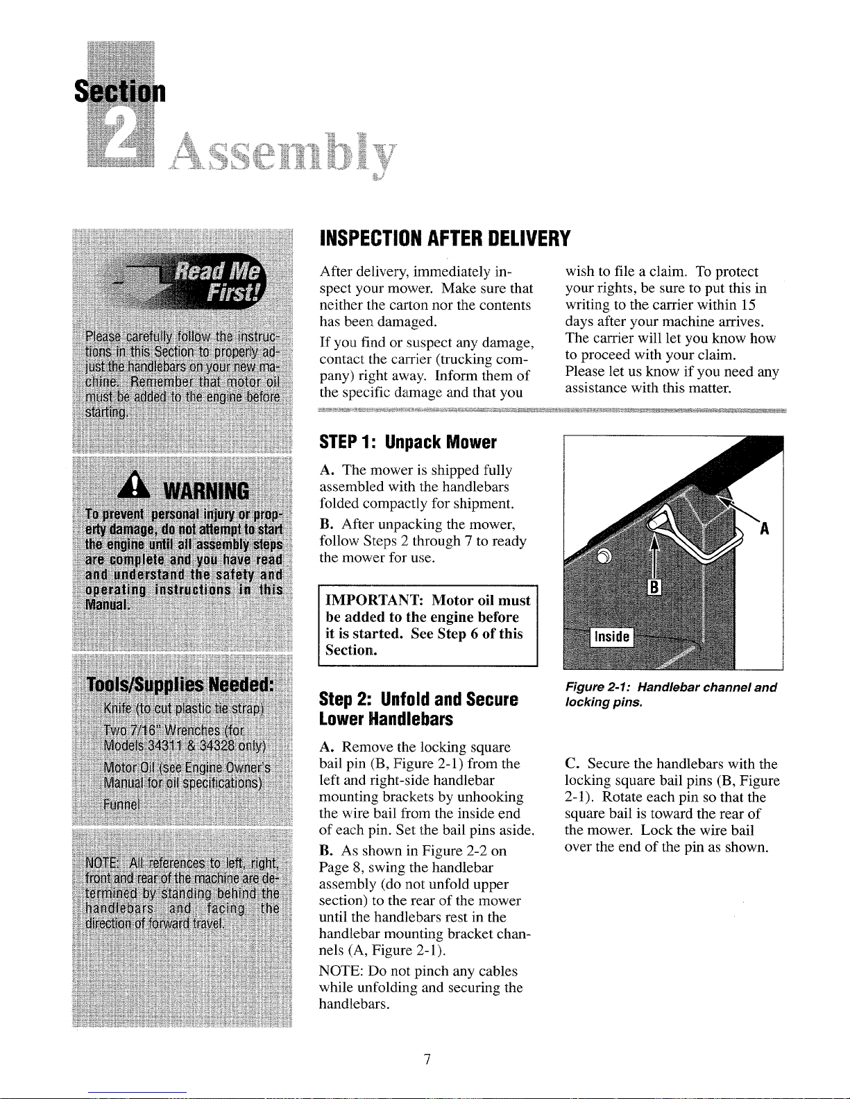
Step 2: Unfold and Secure
Lower Handlebars
A. Remove the locking square
bail pin (B, Figure 2-1) from the
left and right-side handlebar
mounting brackets by unhooking
the wire bail from the inside end
of each pin. Set the bail pins aside.
B. As shown in Figure 2-2 on
Page 8, swing the handlebar
assembly (do not unfold upper
section) to the rear of the mower
until the handlebars rest in the
handlebar mounting bracket chan-
nels (A, Figure 2-1).
NOTE: Do not pinch any cables
while unfolding and securing the
handlebars.
Figure 2-1: Handlebar channel and
locking pins.
C. Secure the handlebars with the
locking square bail pins (B, Figure
2-1). Rotate each pin so that the
square bail is toward the rear of
the mower. Lock the wire bail
over the end of the pin as shown.
Assembi.y
Figure 2-2: Unfold lower handlebar
assembly.
Step 3: Unfold and Secure
Upper Handlebars
NOTE: On some models the
upper adjustment knobs (A, Figure
2-3) are located on the inside of
the handlebars.
A. Loosen the upper adjustment
knobs (A, Figure 2-3) until the
adjustment teeth are disengaged.
Push outward on the sides of the
upper handlebars, and swing the
handlebars upward to the desired
height setting.
B. Align the adjustment teeth and
tighten the knobs.
C. Remove the plastic tie strap
and any cardboard wrapping from
the handlebars.
Figure 2-3: Handlebar position
adjustment (Model 34022 shown).
CAUTION
Sharp cutting blades can
cause serious personal in-
jury. When working near the
mower blade, wear heavy
leather gloves to protect
yourself from the sharp
edges.
Step 4: Connect Battery
Wires and Charge Battery
(Models 34023, 34023C,
34323 and 34323C)
A. Carefully lift right side of
mower so mower rests on left side.
B. Two wires (A and B, Figure 2-
4) are located inside the right rear
corner of the deck.
NOTE: Be sure both wires are
above wheel axle before snapping
the two connectors together.
C. Connect wire lead from battery
(A, Figure 2-4) to wire lead from
main wire harness (B). Position
wires toward top of deck.
D. Gently lower mower to the
ground.
E. Initially charge battery for 24
hours before using electric starter.
See battery charging instructions
on Page 41.
/,
/
\
Figure 2-4: Battery wiring harness
connection.
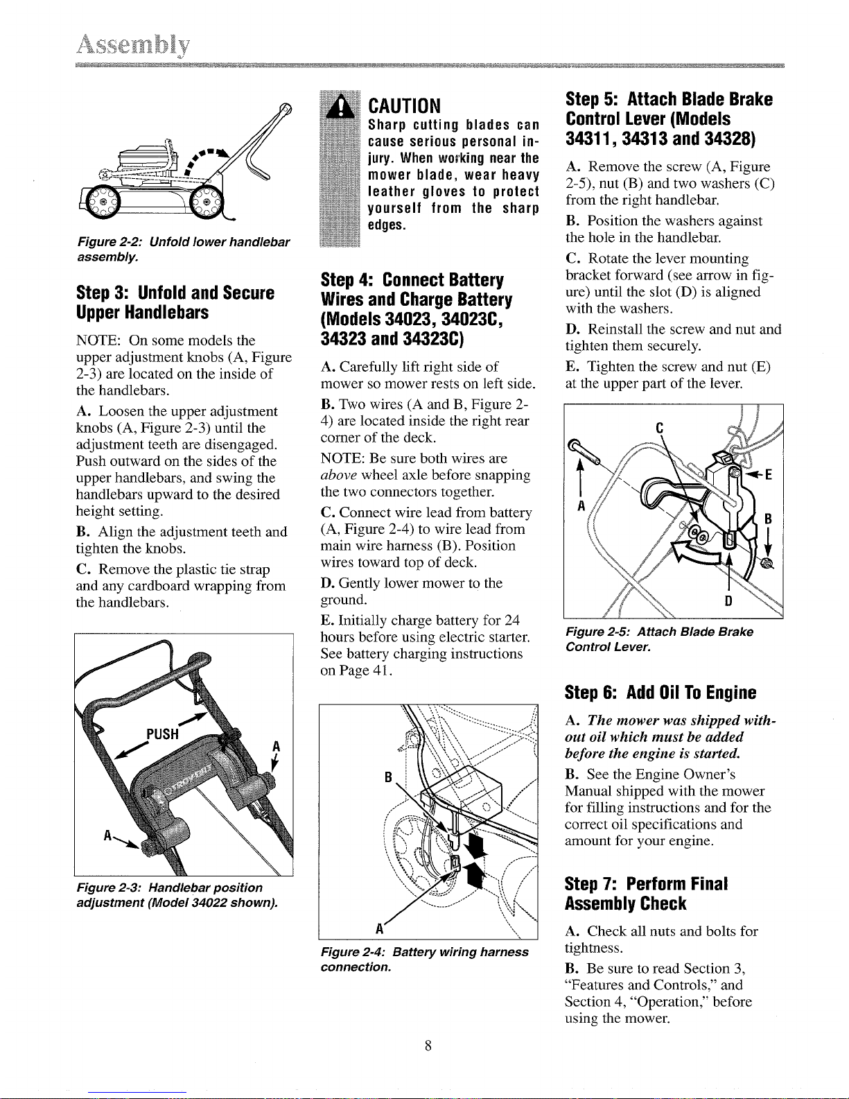
Step 5: Attach Blade Brake
Control Lever (Models
34311,34313 and 34328)
A. Remove the screw (A, Figure
2-5), nut (B) and two washers (C)
from the right handlebar.
B. Position the washers against
the hole in the handlebar.
C. Rotate the lever mounting
bracket forward (see arrow in fig-
ure) until the slot (D) is aligned
with the washers.
D. Reinstall the screw and nut and
tighten them securely.
E. Tighten the screw and nut (E)
at the upper part of the lever.
D
Figure 2-5: Attach Blade Brake
Control Lever.
Step 6: Add Oil To Engine
A. The mower was shipped with-
out oil which must be added
before the engine is started.
B. See the Engine Owner's
Manual shipped with the mower
for filling instructions and for the
correct oil specifications and
amount for your engine.
Step 7: Perform Final
Assembly Check
A. Check all nuts and bolts for
tightness.
B. Be sure to read Section 3,
"Features and Controls," and
Section 4, "Operation," before
using the mower.

FEATURESANDCONTROLSIDENTIFICATION
The following are features and controls found on the various models of the
Mulching Mower. Note that some are common features or controls with
the same location on all models, whereas others are specific to one or more
models. First, read the description and location of features on all models
(Page 10). Then, look for your Model Number for a short description of
the features and controls specific to your model.
All Models (see Page 10)
Engine Recoil Starter
Cover Interlock Switch
Cutting Height Adjustment Handle
Upper Handlebar Position Adjustment Knobs
Locking Square Bail Pins (for Lower Handlebar Release)
In addition to the features mentioned above, each model has the specific
features listed be!ow:
Push Models 34020, 34020C, 34320 & 34320C (see Page 11)
Operator Presence Control Bar (controls operation of engine & blade)
Engine Speed Lever
Single Speed Models 34021, 34021C, 34321 & 34321C (see Page 12)
Operator Presence Control Bar (controls operation of engine & blade)
Engine Speed Lever
Wheel Drive Lever
Variable Speed Models 34022, 34022C, 34322 & 34322C (see Page 13)
Operator Presence Control Bar (controls operation of engine & blade)
Engine Speed Lever
Wheel Drive Lever (variable speed on panel)
Variable Speed/Electric Start Models 34023, 34323 & 34323C (see
Page 14)
Operator Presence Control Bar (controls operation of engine & blade)
Engine Speed Lever (on panel)
Wheel Drive Lever (variable speed on panel)
Ignition Keyswitch (on panel)
Variable Speed/Blade Brake Control Models 34311, 34313 & 34328
(see Page 15)
Blade Brake Control Bar (controls operation of blade)
Engine Speed Lever
Wheel Drive Control Bar (conlrols operation of wheels)
Wheel Speed Adjustment Knob (controls forward wheel speeds)
FEATURESANDCONTROLSONALLMODELS
HandlebarPosition
AdjustmentKnob
EngineRecoil StarterRope
(Handle BehindPanel)
Cuttin_
Height
Adjustment
LockingSquareBail Pin
CoverInterlockSwitch
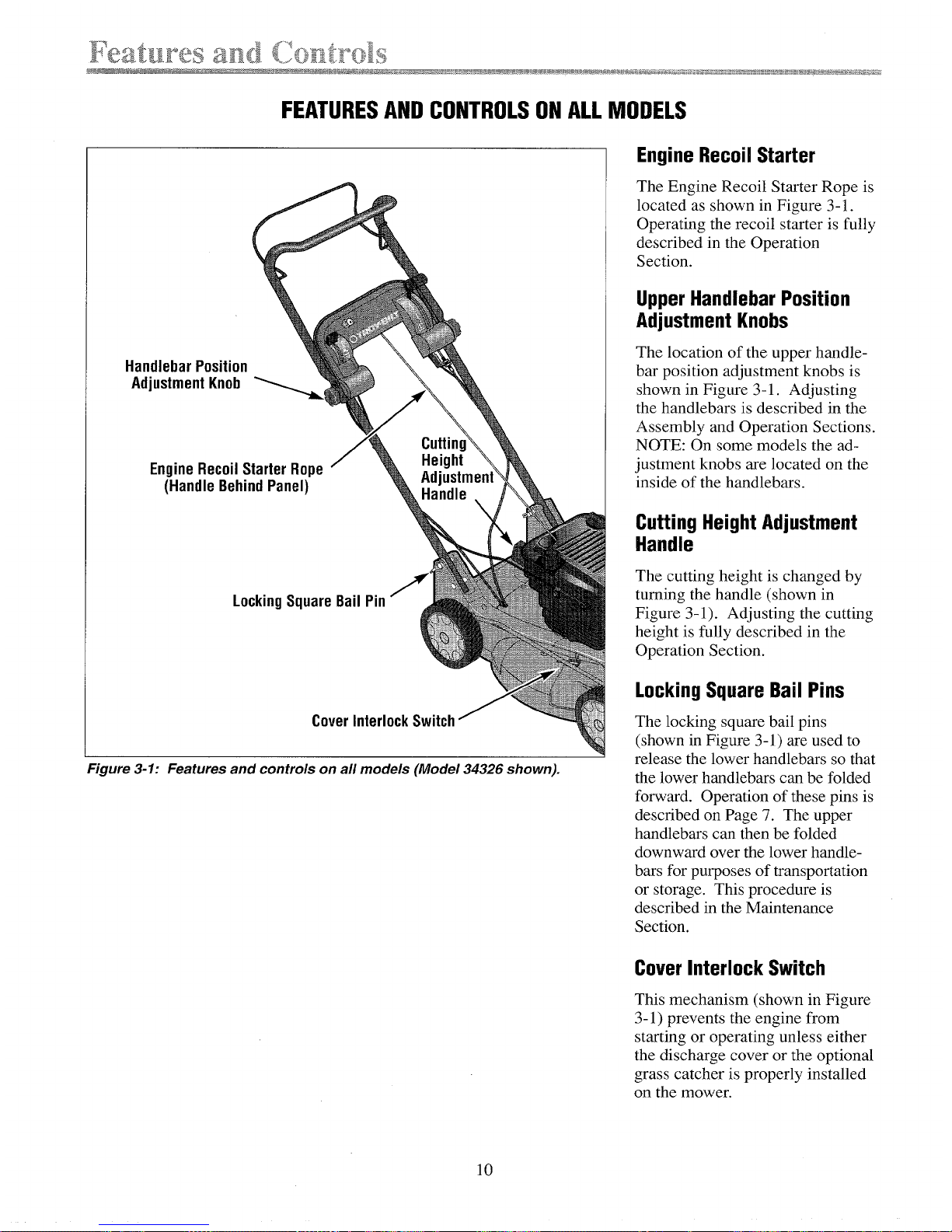
Figure 3-1: Features and controls on all models (Model 34326 shown).
Engine Recoil Starter
The Engine Recoil Starter Rope is
located as shown in Figure 3-1.
Operating the recoil starter is fully
described in the Operation
Section.
Upper Handlebar Position
Adjustment Knobs
The location of the upper handle-
bar position adjustment knobs is
shown in Figure 3-1. Adjusting
the handlebars is described in the
Assembly and Operation Sections.
NOTE: On some models the ad-
justment knobs are located on the
inside of the handlebars.
Cutting Height Adjustment
Handle
The cutting height is changed by
turning the handle (shown in
Figure 3-1). Adjusting the cutting
height is fully described in the
Operation Section.
Locking Square Bail Pins
The locking square bail pins
(shown in Figure 3-1 ) are used to
release the lower handlebars so that
the lower handlebars can be folded
forward. Operation of these pins is
described on Page 7. The upper
handlebars can then be folded
downward over the lower handle-
bars for purposes of transportation
or storage. This procedure is
described in the Maintenance
Section.
CoverInterlock Switch
This mechanism (shown in Figure
3-1) prevents the engine from
starting or operating unless either
the discharge cover or the optional
grass catcher is properly installed
on the mower.
10
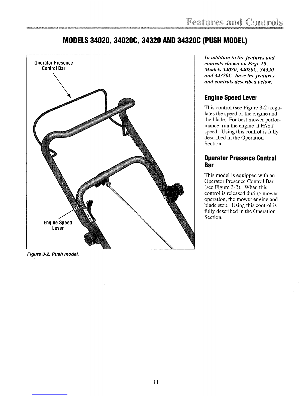
MODELS34020, 34020C, 34320 AND34320C (PUSHMODEL)
Operator Presence
ControlBar
EngineSpeed
Lever
In addition to the features and
controls shown on Page 10,
Models 34020, 34020C, 34320
and 34320C have the features
and controls described below.
Engine Speed Lever
This control (see Figure 3-2) regu-
lates the speed of the engine and
the blade. For best mower perfor-
mance, run the engine at FAST
speed. Using this control is fully
described in the Operation
Section.
Operator Presence Control
Bar
This model is equipped with an
Operator Presence Control Bar
(see Figure 3-2). When this
control is released during mower
operation, the mower engine and
blade stop. Using this control is
fully described in the Operation
Section.
Figure 3-2: Push mode!.
11
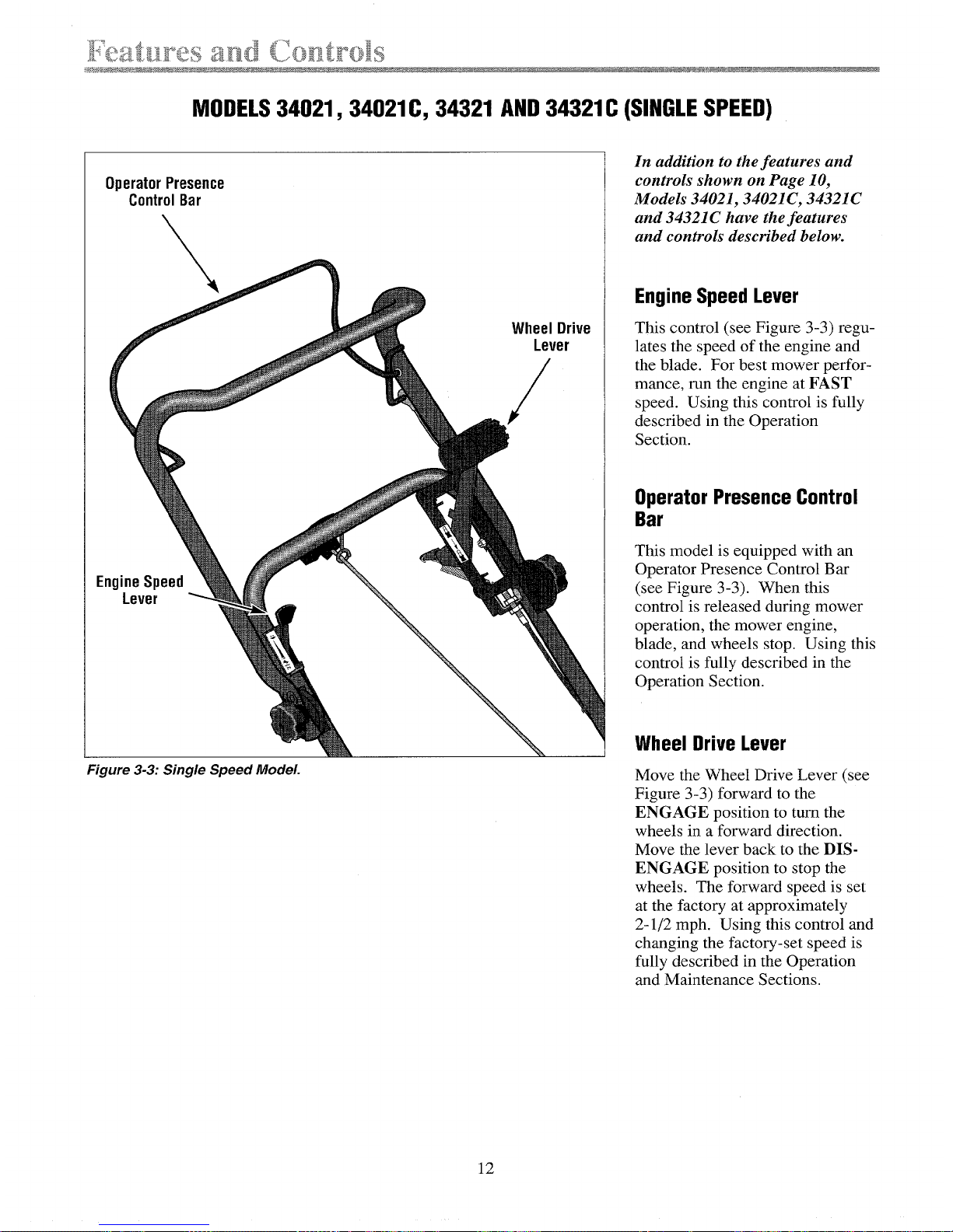
MODELS34021, 34021C, 34321 AND34321C (SINGLESPEED)
Operator Presence
ControlBar
EngineSpeed
Lever
Figure 3-3: Single Speed Model.
Wheel Drive
Lever
/
In addition to the features and
controls shown on Page 10,
Models 34021, 34021C, 34321C
and 34321C have the features
and controls described below.
Engine Speed Lever
This control (see Figure 3-3) regu-
lates the speed of the engine and
the blade. For best mower perfor-
mance, run the engine at FAST
speed. Using this control is fully
described in the Operation
Section.
OperatorPresenceControl
Bar
This model is equipped with an
Operator Presence Control Bar
(see Figure 3-3). When this
control is released during mower
operation, the mower engine,
blade, and wheels stop. Using this
control is fully described in the
Operation Section.
Wheel Drive Lever
Move the Wheel Drive Lever (see
Figure 3-3) forward to the
ENGAGE position to turn the
wheels in a forward direction.
Move the lever back to the DIS-
ENGAGE position to stop the
wheels. The forward speed is set
at the factory at approximately
2-1/2 mph. Using this control and
changing the factory-set speed is
fully described in the Operation
and Maintenance Sections.
12
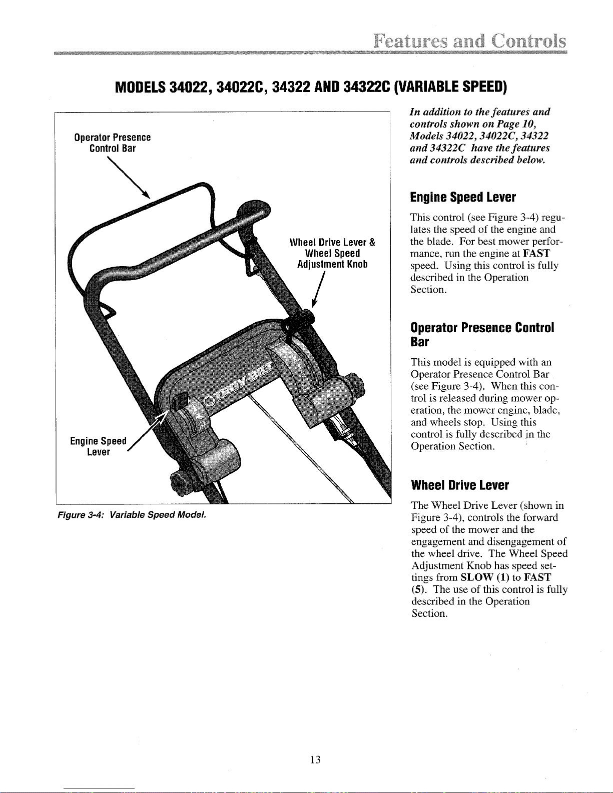
MODELS34022, 34022C, 34322 AND34322C (VARIABLESPEED)
Operator Presence
ControlBar
EngineSpeed
Lever
Wheel Drive Lever&
Wheel Speed
AdjustmentKnob
In addition to the features and
controls shown on Page 10,
Models 34022, 34022C, 34322
and 34322C have the features
and controls described below.
Engine Speed Lever
This control (see Figure 3-4) regu-
lates the speed of the engine and
the blade. For best mower perfor-
mance, run the engine at FAST
speed. Using this control is fully
described in the Operation
Section.
Operator Presence Control
Bar
This model is equipped with an
Operator Presence Control Bar
(see Figure 3-4). When this con-
trol is released during mower op-
eration, the mower engine, blade,
and wheels stop. Using this
control is fully described jn the
Operation Section.
Wheel Drive Lever
Figure 3-4: Variable Speed Model
The Wheel Drive Lever (shown in
Figure 3-4), controls the forward
speed of the mower and the
engagement and disengagement of
the wheel drive. The Wheel Speed
Adjustment Knob has speed set-
tings from SLOW (1) to FAST
(5). The use of this control is fully
described in the Operation
Section.
13
 Loading...