

Page 1
o
$7 50
If-BIL
Owner/Operator
Manual
TRAIL BLAZER
Sickle Bar Mower
« Safety
Models
• Assembly
« Controls
• Operation
• Maintenance
3V2 HP
4 HP
Page 2
ADANGER
Awarning
The mower’s cutter bar can cause serious
personal injury. Read this Owner/Operator Manual thoroughly for precautions you must follow
when operating the mower. Always follow these
precautions.
PLEASE NOTE
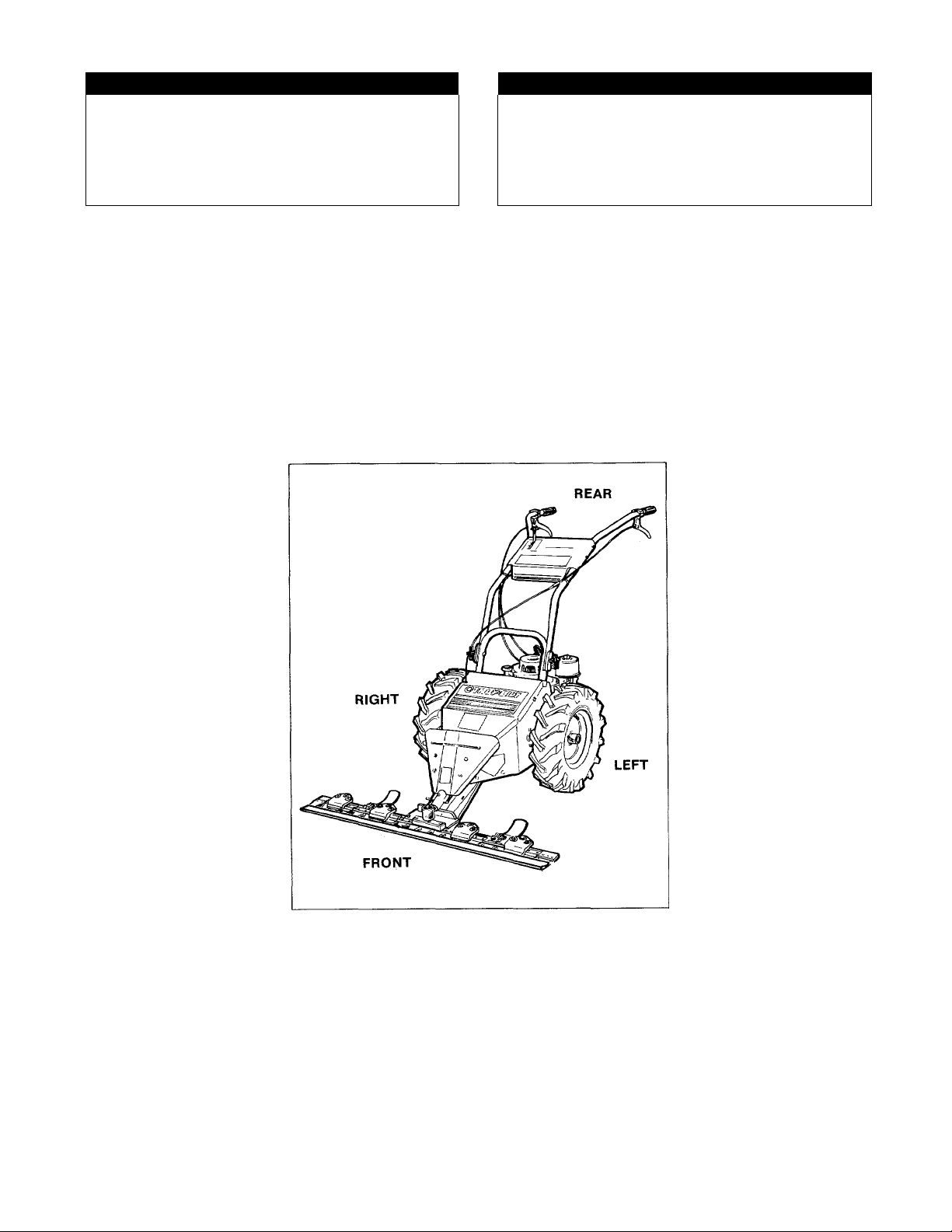
All directions in this Manual are determined from the
operator’s position, standing behind the handlebars
and facing forward. Please refer to the figure below.
Avoid fires due to sparks.
Do not operate engine if spark arrester screen is
loose or damaged.
IMPORTANT!
If you notice any freight damage either at the time of
delivery or later during assembly, make sure that you
notify the truck terminal that delivered your mower that
you intend to file a claim. If you have any problems
with this procedure, please call us so that we can help
you get satisfaction. Our phone numbers are listed on
Page 3 and on the back cover of this manual.
Page 3

TABLE OF CONTENTS
Page
Section 1: Safety.................................................................... 4
Training ............................................................................. 4
Preparation ....................................................................... 4
Operation .......................................................................... 4
Disconnecting the Spark Plug Wire ................................ 5
Maintenance and Storage
Decals ............................................................................... 5
.........................................
Section 2: Easy Assembly
Section 3: Engine and Mower Controls
Blade Drive Lever
Wheel Drive Lever
Cutting Height Adjusters
Handlebar Height Adjustment ........................................13
Engine Throttle Lever .....................................................14
Engine Choke ..................................................................14
Recoil Starter
Engine Ignition Switch
(Electric Start Models)
...........................................................
..........................................................
................................................
...................................................................
.......................................
.........................
... 14
12
12
12
13
14
Section 4: Mower Operation ........................................15
Filling the Engine’s Gas Tank.........................................15
Starting the Mower ..........................................................16
Mowing
Stopping
General Mowing Tips.......................................................17
............................................................................
..........................................................................
16
17
Page
Sections; Maintenance............................................18
Engine Maintenance ...........................................18
Checking the Engine Oil Level and
Adding Oil to the Engine ..............................18
Changing the Engine Oil
5
Air Filter Maintenance
.................................
.....................................
19
19
Spark Arrester .................................................20
Air Cooling System Maintenance
.....................
21
Carburetor Adjustment (Engine
Speed & Mixture) ..........................................21
Engine Ignition System
..................................
21
Spark Plug.......................................................21
Liquid Lock
Mower Maintenance
Lubrication
Removing and Reinstalling the Wheels
.....................................................
...........................................
.......................................................
...........
21
22
22
23
Wheel Drive Belt Removal and
Installation
Wheel Drive Adjustment (General)
...................................................
..................
23
27
Wheel Drive Check.......................................27
Wheel Drive Initial Setting
Wheel Drive Main Adjustment
...........................
.....................
28
28
Cutter Bar Drive Belt Removal and
Installation
Cutter Bar Drive Adjustment (General)
Cutter Bar Drive Check
Cutter Bar Drive Initial Setting
...................................................
...........
...............................
.....................
29
32
32
32
Cutter Bar Drive Main Adjustment ...............33
Cutter Bar Maintenance
...................................
34
Removal and Installation of the
Cutter Bar Assembly.................................34
Blade Guide Maintenance ...........................35
Blade Guide Adjustment...........................36
Removing and Installing the Cutter
Blade Assembly .......................................36
Tightening a Loose Individual Blade
Replacing Individual Blades
.........................
Electric Starting System Maintenance
Battery Charging
.........................................
...........
............
37
38
40
40
Seasonal Charging ......................................40
Battery Removal & Installation
...................
41
Storage....................................................................42
Maintenance Schedule
...........................................
42
Troubleshooting Chart ............................................43
Alphabetical Index
Specifications
.............................
...................................
inside rear cover
inside rear cover
Page 4

Dear Owner:
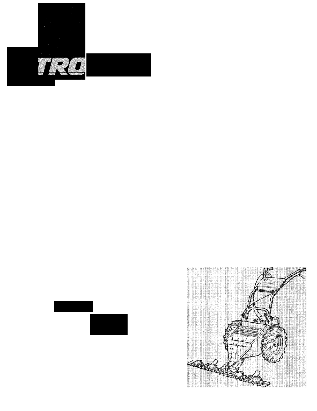
Congratulations on the purchase of your TROY-BILT TRAIL BLAZER® Sickle Bar Mower. You will find this mower
to be a unique and useful piece of equipment that can be used for many projects on your property. You can
use this mower for numerous tasks, such as taming those unsightly areas on your property that you never had
the time to mow, cleaning up any badly overgrown spots that are threatening to surround your out-buildings,
making an occasional pass over the edges of your property to keep your property lines clear, or making a single
path through head-high weeds and saplings to make a nature trail or a cross country trail that can be enjoyed all
year long.
Because of the TROY-BILT TRAIL BLAZER® Mower’s ease of operation and well-balanced build, you can do all
of the above-mentioned projects easily with little more effort than simply walking behind the mower. The mower’s
cutter bar has induction hardened teeth that slice through weeds and small saplings in a single pass, leaving a
wide swath behind.
To help you get the most value from your mower, we’ve prepared this Owner/Operator Manual for your use.
This Manual will tell you how to easily assemble your mower and operate its controls. It also provides you with
easy-to-follow procedures for performing required maintenance.
And, of course, we are never more than a phone call away. If you should ever have any questions about your
mower, or need to order any parts, please call us. Our phone numbers are listed on Page 3 and on the back cover
of this Manual. One of our helpful, friendly Technical Service people will be glad to assist you.
Sincerely,
Dean Leith, Jr.
Sales Manager
RECORD YOUR MOWER’S SERIAL AND
MODEL NUMBERS
The arrow in the photo shows the location of the
serial number and model number decals on your
TRAIL BLAZER® Mower. Please record these numbers
in the spaces below. If you should ever need any
replacement parts, or if you have any questions for
us, we will need to know these numbers. Also please
be sure to tell us if you have an electric start or a
standard start model.
MY TRAIL BLAZER® MOWER IS (CHECK ONE);
□ AN ELECTRIC START MODEL.
□ A STANDARD START MODEL.
ITS SERIAL NUMBER IS
ITS MODEL NUMBER IS
ITS DATE OF DELIVERY WAS.
_____________________________
_____________________________
RECORD YOUR MOWER ENGINE’S
IDENTIFICATION NUMBERS
Please refer to the Briggs & Stratton Operating and
Maintenance Instructions Manual that was included in
the literature package. This manual will show you the
location of the engine’s identification numbers. If you
ever need any engine parts, you will need to provide
its identification numbers.
To obtain engine parts or service, please look in
the yellow pages of your telephone book under
“ENGINES-GASOLINE” or “GASOLINE ENGINES”.
Then look for the name of the nearest Authorized
Briggs & Stratton Service Center. If you have trouble
finding a service shop, please feel free to call us and
we will provide you with the name, telephone number,
and address of the service center nearest you.
Please record the important engine information in
the blank spaces below. This will give you a handy
reference for later use.
ENGINE HORSEPOWER RATING
ENGINE MODELATYPE/
CODE NUMBER
________
_____________________
Page 5

FOR SERVICE OR PARTS:
If you should ever need service assistance or
replacement parts for your mower, call us at the
numbers listed below:
TROY-BILT MANUFACTURING CO.
102nd St. & 9th Ave., Troy, New York 12180
For Technical Service, call Toll-Free: 1-800-833-6990
For Parts Sales, call Toll-Free: 1-800-648-6776
M-F 8 a.m. to 7 p.m.
Sat. 9 a.m. to 4:00 p.m.
GARDEN WAY BRANCH CANADA
1515 Matheson Blvd. E, Unit B11
Mississauga, Ontario L4W 2P5
Call Toll-Free: 1-800-225-3585
M-F 8 .m. to 4:30 p.m.
If you are ordering parts for your mower, please
give us the following information:
1. The serial number of your mower.
2. Whether you have an electric start model or a
standard start model.
3. The PART NUMBER of the part you need (from
the TRAIL BLAZER® Mower Parts Catalog).
4. The PART DESCRIPTION of the part you need
(from the TRAIL BLAZER® Mower Parts Catalog).
5. The QUANTITY of that particular part that you
need.
(Please remember that you can get many of the
common hardware items from a nearby well-stocked
hardware store as well as from us.)
AWARNING TO ALL CALIFORNIA MOWER OPERATORS
Under California Law, you are not permitted to operate an internal combustion engine using hydrocarbon
fuels on any forest-covered, brush-covered, or grass-covered land, or land covered with grain, hay, or other
flammable agricultural crop, without an engine spark arrester in continuous effective working order. The
engine on your mower, like most lawn or garden equipment, is an internal combustion engine that burns
gasoline (a hydrocarbon fuel); therefore it must be equipped with a spark arrester muffler in proper working
order. The spark arrester must be attached to the engine exhaust system in such a manner that flames or heat
from the system will not ignite flammable material. Failure of the operator to comply with this regulation is a
misdemeanor under California Law. Other states may have similar laws. Federal laws apply on Federal lands.
The TRAIL BLAZER® Mower is equipped with a
screen-type spark arrester on its muffler.
Please refer to Page 20 in this Manual and to the
Briggs & Stratton Operating and Maintenance Instruc
tions Manual for specific inspection and maintenance
procedures for the spark arrester.
Page 6

SECTION 1: SAFETY
IMPORTANT—Safe Operation Practices for Sickle Bar Mowers
When operating or servicing the mower always
follow the safe operating practices described in this
Section. If you should ever lend this mower to another
person, make sure that he or she understands the
safe operation of the mower.
TRAINING
1. Read this Owner/Operator Manual, the separate
engine owner’s manual, and any other literature you
may have received before you use the mower. Be
thoroughly familiar with the controls and proper use
of the mower. Know how to stop the mower and
disengage its controls quickly in case of an emergency.
2. Never allow children to operate the mower. Do not
allow adults to operate the mower without proper
instruction. Do not allow irresponsible adults to oper
ate the mower.
3. Keep the area of operation clear of all persons,
particularly small children, and pets.
PREPARATION
1. Thoroughly inspect the area where the mower is to
be used. Remove all metal debris, limbs, and other
hazards. Also inspect this area for holes, ruts, or
bumps. Uneven terrain could overturn the mower. Be
aware that tall vegetation can hide many hazards.
2. Do not operate the mower when barefoot or when
wearing open sandals. Always wear substantial foot
wear which will protect your feet and help improve
traction.
3. Do not wear loose fitting clothing or jewelry that
could get caught in moving parts. Also be aware that
vines, branches, etc. can snag loose fitting clothing or
jewelry.
4. Remove any rings or other metal jewelry when
working on or near the electric starting system.
5. Before starting the engine, make sure that the
plastic blade protector is removed from the blade and
that both handlebar levers are disengaged (released).
Also check the muffler’s spark arrester screen for
security and damage.
6. Mow only in daylight.
7. Never operate the mower in wet grass. Always be
sure of your footing; keep a firm hold on the handle
bar grips, and walk, never run.
8. Never operate the mower without the weed deflec
tor and all guards in place (except for the plastic
blade protector, which should be removed before
starting the engine).
9. Never attempt to disconnect or remove guards or
other safety devices, or to defeat the purpose of
these safefy devices.
10. Gasoline is highly flammable and its vapors are
explosive. Handle it with extreme care. Use an
4 approved fuel container.
If you should ever have any questions about oper
ating or servicing your TRAIL BLAZER® Mower, please
call us immediately. One of our trained technical
service representatives will be happy to assist you.
Our phone numbers are listed on Page 3 and on the
back cover of this Manual.
11. Check the gas level in the gas tank before starting
the engine. Do not fill the gas tank when the mower is
indoors, when the mower’s engine is running, or when
the mower’s engine is hot. Allow the mower’s engine
to cool for several minutes before filling the gas tank.
Reinstall the gas tank cap securely and clean up any
spilled gasoline before starting the engine.
12. Keep smoking materials, sparks, and flame away
from the gas tank and the fuel container.
13. Move the mower away from gas fumes before
starting the engine.
14. If you are mowing in a dry area, do not smoke.
Do not smoke while mowing.
15. Do not charge the battery (on electric start mod
els) in an airtight space.
16. When charging the (electric start) mower’s bat
tery, do not use a battery charger other than the one
provided with the mower.
17. The electric start mower’s battery contains toxic
materials. Do not damage the battery case. If the case
is broken or damaged, avoid contact with the battery
contents.
18. Dispose of the battery properly. Check with local
authorities for proper disposal methods.
19. Do not operate the mower if the cutter bar assem
bly is not securely installed.
OPERATION
1. Before each use, check the operation of the han
dlebar levers. See Page 16 in this Manual for specific
instructions. Do not use the mower if either handlebar
lever is not functioning properly.
2. Do not put hands or feet near or under any moving
parts. Keep clear of the cutter bar at all times when
the engine is running.
3. Keep the plastic blade protector on the blade until
you are ready to start the engine.
4. Before removing or installing the plastic blade
protector: shut the engine off, disconnect the spark
plug wire and prevent it from touching the spark plug.
On electric start models, also remove the Engine
Ignition key from the keyswitch.
5. Do not change the engine governor settings or
overspeed the engine.
6. Stop the cutter bar blade when crossing gravel
drives, walks, or roads.
7. Watch for traffic when operating near, or when
crossing roadways.
Page 7

SAFETY
8. Stop both the cutter bar blade and the wheel drive
when you are approached by any child, inattentive
person, or pet.
9. Before inspecting, cleaning, adjusting, or repairing
the mower or cutter bar: stop the engine, disconnect
the spark plug wire and prevent it from touching the
spark plug, wait for all moving parts to stop, and
reinstall the plastic blade protector on the blade. On
electric start models, also remove the Engine Ignition
key from the keyswitch.
10. Never leave the operator’s position while the
mower’s engine is running. Stop the engine, discon
nect the spark plug wire and prevent it from touching
the spark plug to help prevent accidental starting. Also,
remove the Engine Ignition key from the keyswitch on
electric start models to help prevent accidental starting
or unauthorized use.
11. If the mower should start to vibrate abnormally,
stop the engine, disconnect the spark plug wire and
prevent it from touching the spark plug. Also, remove
the Engine ignition key from the keyswitch on electric
start models. Wait for ail moving parts to completely
stop and then inspect the mower for damage. Repair
the damage before restarting the engine and operating
the mower.
12. Do not run the engine in an enclosed area.
Engine exhaust contains carbon monoxide gas,
a deadly poison that is odorless, colorless and
tasteless.
13. Do not mow excessively steep slopes.
14. Keep all movements on a slope slow and gradual.
Do not make sudden changes in speed or direction.
15. Do not touch engine parts which may be hot from
operation. Allow parts to cool before inspecting,
cleaning, or repairing.
16. Whenever you pull the mower rearward, release
both handlebar levers. Always check behind you for
hazards when backing up.
17. If you’re not mowing, disengage the blade drive.
18. Do not operate the mower while under the influ
ence of alcohol or drugs.
19. Do not mow near drop-offs, ditches, or embank
ments. If the mower’s wheel goes over the edge, or if
the edge caves in, the mower could suddenly overturn.
20. Keep children out of the mowing area. Keep them
under the watchful eye of an adult other than the
person operating the mower. Never assume that chil
dren will remain where you last saw them.
21. Before you back the mower up, and while you’re
backing it up, be sure to look behind you for small
children.
22. Never attempt to carry children on the mower.
They could fall off and be seriously injured, or they
could interfere with the safe operation of the mower.
23. Use extra care when approaching blind corners,
shrubs, trees, and any other object that may obscure
vision.
24. When removing the cutter bar blade from the
cutter bar assembly, wear sturdy leather gloves to
help prevent the blades from accidentally pinching or
cutting your fingers or hands.
Disconnecting the Spark Plug Wire
Whenever you perform any type of cleaning, inspec
tion, or maintenance on the mower, shut the engine
off and then disconnect the spark plug wire from the
spark plug. Then prevent the wire from touching the
spark plug by placing the spark plug wire’s boot on
the V-shaped holder that is on the rear of the engine.
See the photo below.
Preventing the spark plug wire from touching the
spark plug helps to prevent the engine from being
accidentally started.
Preventing the spark plug wire from touching the spark plug.
MAINTENANCE AND STORAGE
1. Keep all nuts, bolts, and screws tight to be sure
that the equipment is in safe working condition.
2. If the mower has gasoline in its gas tank, do not
store it inside a building where fumes from the gaso
line could reach an open flame or spark.
3. Allow the engine to cool before storing the mower
in any enclosure.
4. To reduce fire hazard, keep the engine free of
grass, leaves, or excessive grease.
5. Store gasoline in a cool, well-ventilated area, safely
away from any spark- or flame-producing equipment.
Store gasoline in an approved container, safely out of
the reach of children.
6. Before inspecting, cleaning, adjusting, or repairing
the mower: Stop the engine, disconnect the spark
plug wire and prevent it from touching the spark plug,
wait for all moving parts to stop, and reinstall the
plastic blade protector on the blade. On electric start
models, also remove the Engine Ignition key from the
keyswitch.
7. Do not allow children to be around you when you
are working on the mower.
DECALS
We’ve placed operating and safety decals on the
mower to help you when operating the mower or to
warn you of any hazards. If any of these decals is
missing, iilegible, or damaged, please contact us
immediately for replacements. Please refer to your
TRAIL BLAZER® Parts Catalog for decal location and
replacement information.
Page 8

SECTION 2: EASY ASSEMBLY
Please follow the assembly steps given in this Sec
tion to properly assemble your mower. These steps
will not take very long and they will assure you of
having assembled your mower correctly.
To assemble the mower, you’ll need the following
items:
1. One pair of scissors.
2. One flat-tipped screwdriver.
3. One quart of high quality engine oil. (See “Specifi
cations” on the inside rear cover of this Manual for
recommended types of oil.)
4. One 3/8-inch wrench.
5. A piece of wood (to tap the handle onto the
Throttle Lever).
Step 1: Check your Parts
We’ve carefully packed your mower here at the
factory. After unpacking it, compare the contents of
the cartons to Photo 2-1 to make sure that you have
the necessary parts to assemble your mower. If any
parts are missing, please call us for replacements.
The following list of components is keyed to the
callouts in Photo 2-1.
1. The upper handlebar assembly.
2. The mower body/engine assembly.
Before you begin assembly, please read this Sec
tion all the way through to familiarize yourself with the
assembly steps. Then gather the necessary tools.
6.
A 13 MM (millimeter) wrench. (You can substitute
a V2-inch wrench).
7.
A clean funnel.
8.
For electric start mowers, you’ll also need a
13/16-inch wrench (you can substitute a large
adjustable wrench).
9.
An assistant to help steady the mower.
10.
Grease, multi-purpose type.
The mower hardware packages.
3.
4.
The cutter bar assembly, which consists of;
a. The ledger bar.
b. The cutter blade.
c. The plastic blade protector.
5.
The drive socket.
6.
The drive pin.
7.
Two forward height adjuster halves.
Two rear height adjuster halves.
8.
m .
Photo 2-1: The contents of the shipping cartons.
Page 9

Open the hardware packages. Compare their con
tents with Photo 2-2 and the following list. If any
pieces are missing, call us for replacements.
1. Two handlebar lock clamps.
2. Two handlebar knobs.
3. Two handlebar star washers.
4. Tie straps (four for electric start models; two for
standard start models).
5. Two curved head handlebar bolts.
6. Two #10 lockwashers.
7. Two 10-32 nuts.
8. Two 10-32 X Va-inch slotted head screws.
9. One keyswitch (with nut and lockwasher).*
10. One pair of keys.*
11. One battery charger.*
12. Two 8 MM X 20 MM hex head screws.
13. Two 5/16-inch lockwashers.
14. Four 5/16-18 X iy4-inch carriage bolts.
15. Four 5/16-18 locknuts.
16. Throttle Lever knob.
17. Height adjuster hardware (not shown):
a. Two U-bolts.
b. Four U-bolt nuts.
c. Four flat washers for U-bolts.
d. Four 8MM X 30MM carriage bolts.
e. Four 8MM flat washers.
f. Four 8MM lock nuts.
* Electric start models only.
EASY ASSEMBLY
6,8
9
10
^ mm
12
13
O
c>
15
Photo 2-2: The contents of the hardware packages.
14
16
Step 2: Attaching the Handlebars
1. Slide the upper handlebars into position over the
lower handlebars and align the holes.
NOTE
Use the upper set of holes (in the lower handle
bars) for the higher handlebar height position.
Use the lower set of holes for the lower handle
bar height position.
2. From the inner side, push one of the curved head
handlebar bolts through these holes.
3. Place a handlebar lock clamp over the end of this
bolt. The curved side of the lock clamp faces in.
4. Place a lockwasher on the bolt.
5. Install a handlebar knob on the bolt.
6. Repeat Steps 2 through 5 for the other side of the
handlebars. Very securely tighten both handlebar
knobs.
NOTE
The lower handlebars are rubber mounted at
their lower end to help reduce vibration to the
operator. This may make them feel somewhat
loose, however this is normal.
Photo 2-3: Attaching the handlebars.
Page 10
EASY ASSEMBLY
Step 3: Installing the Throttle Lever
1. The throttle cable is already attached to the Throt
tle Lever and the carburetor. Unwrap the throttle cable
and lever from the mower.
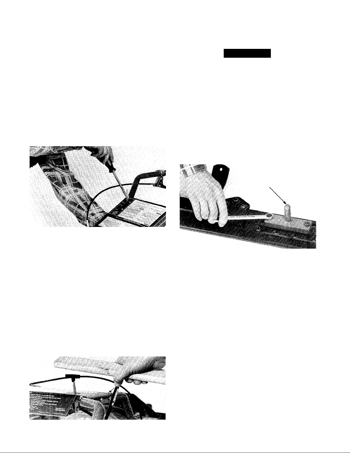
2. From underneath the control panel, insert the
Throttle Lever’s handle up, through the small rectan
gular cut-out in the control panel.
3. From above the control panel, insert one of the
#10-32 X Vz-inch screws down through one of the
cut-outs in the control panel decal. Make sure that
this screw goes through the hole in the base of the
Throttle Lever. Loosely install one of the #10 lockwashers and one of the #10-32 nuts on this screw.
4. Install the second screw, lockwasher, and nut in
the remaining hole. Then tighten both nuts with a
%-inch wrench and screwdriver.
Step 4: Assembling and Installing the Cutter Bar
À CAUTION
The cutter blades are sharp. Keep the plastic
blade protector on the cutter bar when working
on or near the cutter bar.
Failure to do so could result in personal injury
or property damage.
1. If the drive pin is not installed on the cutter blade,
place it on top of the blade. Align the holes in the
base of the drive pin with the holes in the cutter bar.
Secure the drive pin in place with two 8 MM x 25 MM
bolts and two 8 MM lockwashers. Use a 13 MM (or a
Vz-inch) wrench to evenly and securely tighten both
bolts. See Photo 2-6.
APPLY
GREASE
Photo 2-4: Installing the throttle lever.
5. Move the Throttle Lever forward and backward
several times. If the lever binds or does not have full
travel, loosen both nuts that you installed in Steps 3
and 4. From underneath the control panel, push the
base of the Throttle Lever slightly to the right.
Retighten both nuts and again check the Throttle
Lever for free movement. If the Throttle Lever should
still not move, push the carburetor's throttle arm
(where the lower end of the Throttle Lever cable is
secured) to the left. (Occasionally dried paint on the
throttle arm pivot keeps it from moving.)
6. Place the Throttle Lever knob on top of the Throttle
Lever handle. Use a piece of wood to gently tap the
knob onto the Throttle Lever handle.
Photo 2-6: Installing the drive pin.
2. Grasp the drive pin with one hand. Steady the cut
ter bar with your other hand. Try to move the cutter
blade from side to side. Occasionally dried paint will
prevent the blade from moving. If you can’t move the
blade, rap the side of the drive pin with a rubber mal
let to break the cutter blade free of the dried paint.
3. Place the drive socket on the drive pin. Place the
cutter bar assembly in front of the mower's nose
piece.
4. Lubricate the drive pin with multi-purpose grease.
5. Have an assistant push down on the handlebars to
very slightly raise the nose of the mower.
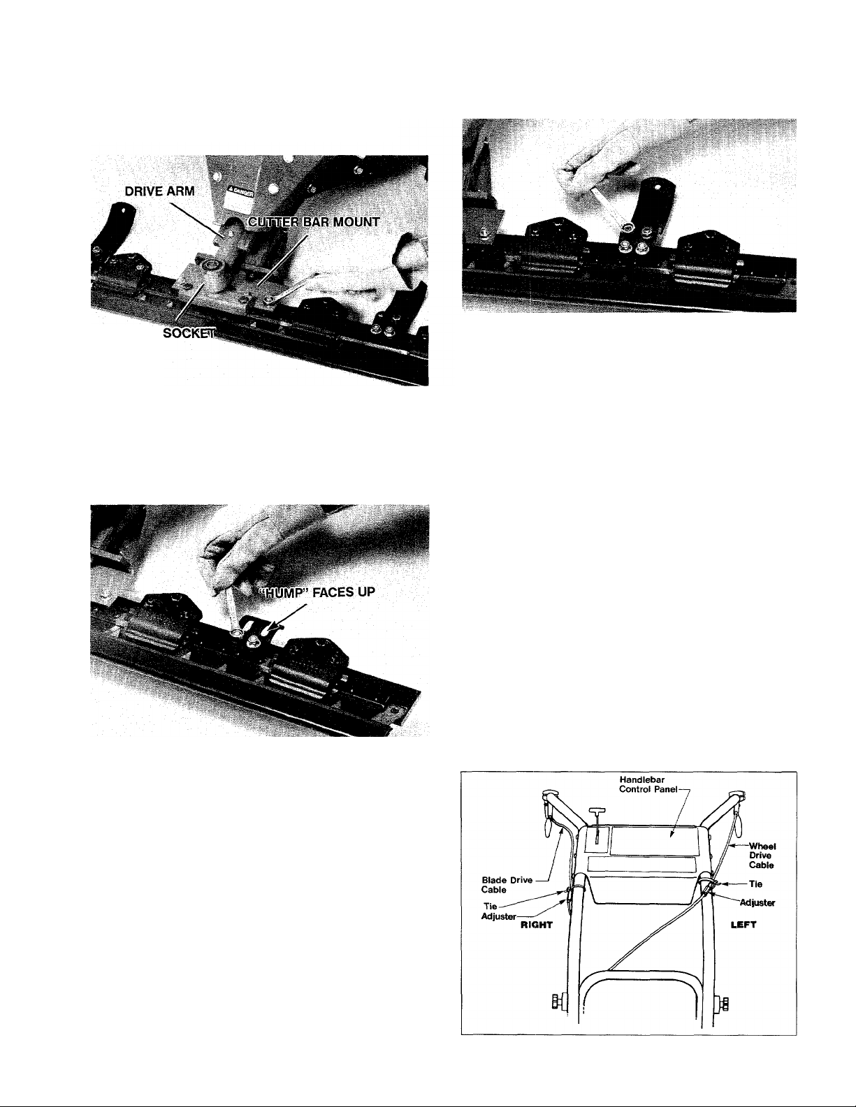
6. Slowly slide the cutter bar assembly rearward.
Make sure that; a) the cutter bar mount rests on top
of the cutter bar and its four holes align with the four
(square) holes in the cutter bar mount, and b) the
shaft on the drive socket enters the hole in the front
of the drive arm.
8 Photo 2-5; Installing the throttle lever knob.
7. From underneath, insert a 5/16-18 x VA-inch car
riage bolt up through one of the holes in the cutter
bar. Loosely install a 5/16-18 nut on this bolt. Repeat
Page 11
this for the remaining three holes. Then tighten ail
four nuts.
EASY ASSEMBLY
DRIVE
Photo 2-7: Installing the cutter bar assembly
8. Place the forward (shorter) half of one of the height
adjusters beneath the rear of the cutter bar. Make sure
that the “hump” on the height adjuster faces up. Align
the two holes in this half of the height adjuster with
the two holes in the rear of the cutter bar. See Photo 2-8.
Photo 2-8: Installing the forward half of the height adjuster.
Photo 2-9: Installing the rear half of the height adjuster.
12. Repeat Steps 8 through 11 for the remaining side
of the cutter bar and height adjuster halves.
13. Flave your assistant lower the nose of the mower.
NOTE
To adjust the height adjusters for blade cutting
height, piease refer to “Cutting Fleight Adjusters”
in Section 3 of this Manual.
Step 5: Attach the Tie Straps (Standard Start
Models Only)
NOTE
If you have an electric start model, the tie straps
wiil be installed in Step 9.
1. On the right-hand handlebar, loop a tie strap
(serrated side faces in) around the handiebar, the
biade drive lever control cable and the throttle cable.
Make sure that the strap is located ABOVE the adjuster
assembly on the control cable. See Figure 2-10.
Tighten the strap and trim off any excess iength.
2. Use a second tie to attach the wheel drive lever
control cable to the left-hand handlebar. Again, make
sure that the strap is located ABOVE the adjuster
assembly on the cable.
9. From underneath, insert two 8MM x 30MM car
riage bolts up through the holes in the height adjuster
and blade. Place an 8MM flat washer and an 8MM
lock nut on each of these carriage bolts. Use a 13MM
(or a Va-inch) wrench to evenly and securely tighten
both of these nuts.
NOTE
Use care to not use the 5/16-18 nuts on the
8MM carriage bolts. Although it is possibie to
make them fit, you will ruin the bolt.
10. Place the rear (longer) half of the height adjuster
(again, with its “hump” facing up) beneath the for
ward half of the height adjuster.
11. From underneath, insert a U-bolt through the two
holes in the height adjuster halves. Place a flat washer
and a locknut on each of the threaded ends of the U-bolt.
Use a Vainch wrench to evenly tighten the nuts.
Figure 2-10: Attaching the tie straps (standard start models
only).
Page 12

EASY ASSEMBLY
Step 6: Add Oil to the Engine
1. Push the mower to a level area.
2. Unscrew the dipstick from the engine. Wipe the
dipstick clean.
3. Insert a clean funnel into the oil fill tube as shown
in Photo 2-11.
4. Pour the oil into the engine. The engine will hold
approximately Vk pints. See Photo 2-11.
NOTE
Please refer to “Specifications” on the inside
rear cover of this Manual to determine the type
of oil to add to the engine.
5. Remove the funnel. Screw the dipstick back into
the oil fill tube. Unscrew the dipstick and check the
oil level. It should be up to the FULL mark on the
dipstick.
If it is not up to this level, re-insert the funnel into
the oil fill tube. Then slowly add more oil until the oil
level is correct. While you’re adding the oil, frequently
pause and check the oil level with the dipstick to
prevent overfilling.
Photo 2-11: Adding oil to the engine.
Step 7: Check Tire Air Pressure
Use an automotive-type tire pressure gauge to
check the air pressure in both tires. The tires may
have been over-inflated for shipping purposes. Make
sure that the air pressure in both tires is the same or
the mower could pull to one side. The correct tire
pressure is from 10 to 20 pounds per square inch (PSI).
If you have a standard start TRAIL BLAZER® Mower, you
have now finished assembling it. Before you begin opera
tion, review Section 1: Safety, and read Sections 3 and 4 to
make sure that you know how to properly and safely operate
your new mower.
If you have an electric start TRAIL BLAZER® Mower, you
will have a few additional assembly steps to complete to
assemble some of the electric starting system parts on the
mower. Please go on to these following steps.
Step 8: Installing the Keyswitch
1. Unscrew the large nut off the keyswitch. Remove
the large toothed lockwasher from the keyswitch.
2. From underneath the mower’s control panel, insert
the threaded end of the keyswitch into the hole in the
rear of the control panel. (The hole for the keyswitch is
marked “ENGINE IGNITION’’.)
3. Place the large toothed lockwasher back onto the
keyswitch. Reinstall the nut on the keyswitch. Use a
13/16-inch wrench (or a large adjustable wrench) to
securely tighten the nut.
NUT LOCKWASHER
10
Photo 2-12: Installing the keyswitch.
Page 13
EASY ASSEMBLY
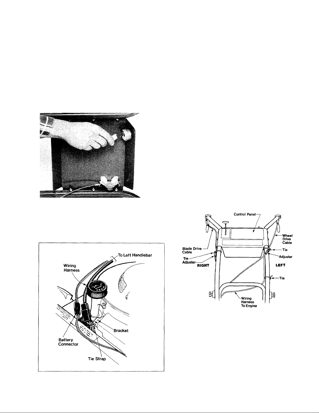
Step 9: Connecting the Wiring Harness
1. Unwrap the wiring harness from the mower.
2. Route the wiring harness beneath the left-hand
handlebar tube. Plug the connector at the top of the
wiring harness into the back of the keyswitch. (You can
attach the connector to the two keyswitch terminals
either way.)
3. For now, leave the plug on the lower end of the
wiring harness disconnected. You’ll connect it later,
after you’ve charged the battery.
5. Move the lower part of the wiring harness to the
right and secure it to the engine’s bracket with the tie
strap as shown in Figure 2-14. Make sure that the
large connector on the wiring harness is ABOVE the tie
strap. Be certain that the battery connector wires are
NOT secured to the engine’s bracket with the tie strap.
6. Secure the upper part of the wiring harness to the
left-hand handlebar tube (above the lock clamp) with
a wide tie strap as shown in Figure 2-15. Make sure
that the serrated side of the strap faces in when you
loop it around the handlebar. After tightening the strap,
snip off any excess length.
7. Use another wide tie strap to secure the Wheel
Drive Cable and the wiring harness to the left-hand
handlebar tube below the handlebar’s control panel
as shown in Figure 2-15. Make sure that the tie strap
is located ABOVE the cable adjuster.
8. Use another wide tie strap to secure the Blade
Drive Cable and the throttle cable to the right-hand
handlebar tube as shown in Figure 2-15. Make sure
that the tie strap is located ABOVE the cable adjuster.
Photo 2-13: Attaching the Wiring Harness to the Keyswitch.
4. Insert the narrow plastic tie strap into the hole in
the bracket that is located on the front part of the
engine housing (to the left of the oil fill tube).
See Figure 2-14.
Figure 2-14: Secure the lower end of the wiring harness to
the engine bracket (electric start models).
Handlebar
Figure 2-15: Attaching the tie straps (electric start models).
Step 10: Charge the Battery
Charge the mower’s battery by following the battery
charging instructions given on Page 40 of this Manual.
After you’ve charged the battery, you’ve finished
assembling the mower. Before operating the mower,
be sure to review Section 1: Safety, and read Sec
tions 3 and 4 to make sure that you know how to
properly and safely operate your new mower.
11
Page 14
SECTION 3: ENGINE AND MOWER CONTROLS
This Section shows the location and describes the
function of the various mower and engine controls
you will need to use when operating the mower.
After reading this Section and familiarizing yourself
with the various controls, please refer to “Section 4:
Operation” for step-by-step engine starting and
mower operation instructions.
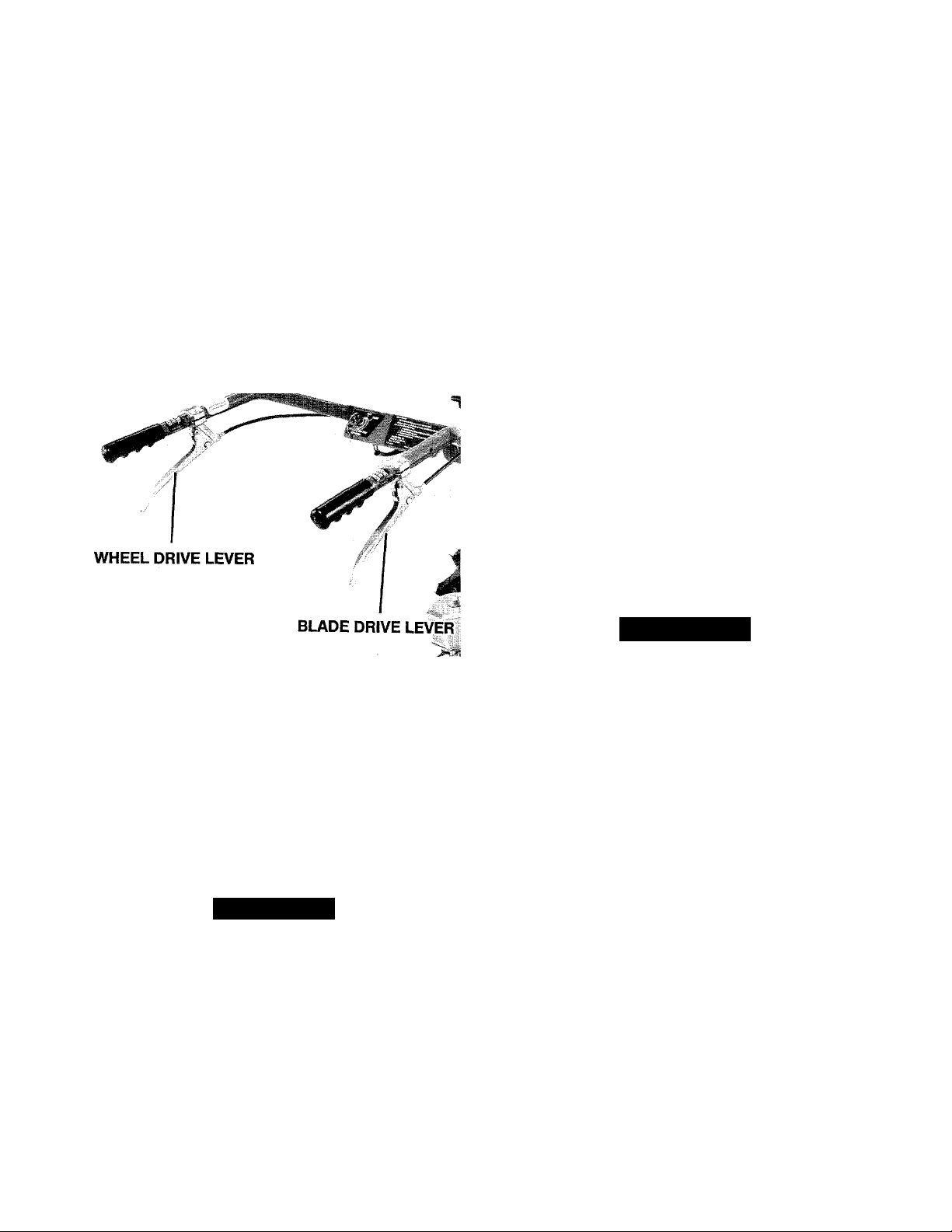
Wheel Drive Lever
This lever is located beneath the left-hand handle
bar grip. To make the mower’s wheels turn (when the
engine is running) you simply rest your left hand on
the left-hand handlebar grip and squeeze the lever
upward. The wheels will begin turning and will
continue to turn as long as you are squeezing the
Wheel Drive Lever.
To stop the wheels from turning, simply release the
Wheel Drive Lever.
Photo 3-1: The handlebar control levers.
Blade Drive Lever
This lever is located beneath the right-hand handle
bar grip. To operate the cutter bar (when the engine is
running) you simply rest your right hand on the
right-hand handlebar grip and squeeze the lever
upward. The cutter bar will begin oscillating (moving
back and forth) and will continue to do so as long as
you are squeezing the Blade Drive Lever.
To stop the cutter bar from oscillating, simply
release the Blade Drive Lever.
ADANGER
If the cutter bar does not stop oscillating when
you release the Blade Drive Lever, or if it oscillates
before you squeeze this lever, shut the mower’s
engine off, wait until it cools, disconnect the spark
plug wire and prevent it from touching the spark
plug. Do not use the mower until the cutter bar
drive mechanism is repaired so that the cutter
bar stops oscillating when the Blade Drive Lever
is released. See “Cutter Bar Drive Adjustment
(General)” in Section 5 of this Manual.
^WARNING
If the wheels do not stop turning when you release
the Wheel Drive Lever, shut the mower’s engine
off, wait until the engine cools, disconnect the
spark plug wire and prevent it from touching the
spark plug. Do not use the mower until the wheel
drive mechanism is repaired so that the wheeis
stop turning when the Wheel Drive Lever is re
leased. See “Wheel Drive Adjustment (General)”
in Section 5 of this Manual.
Failure to do so could result in personal injury or
property damage.
12
Failure to follow this instruction could result in
personal injury or property damage.
Page 15

MOWER CONTROLS
Cutting Height Adjusters
There are two cutting height adjusters, one on each
side of the rear end of the cutter bar. These adjusters
are used to raise or lower the blade’s cutting height.
You can adjust the blade’s cutting height from approx
imately 11/4-inch to 5-inches.
To prevent excessive wear on the blade, set both
height adjusters so that the blade is raised off the
ground and will not dig into the ground.
To change the cutter bar’s cutting height;
A CAUTION
Before changing the cutter bar’s cutting height,
shut the engine off, disconnect the spark plug
wire and prevent it from touching the spark plug,
and reinstall the plastic blade protector on the
front of the cutter bar. On electric start models,
also remove the Engine Ignition key from the
key switch.
Failure to do so could result in personal injury or
property damage.
1. Move the mower to a flat area such as a paved
driveway or a garage floor.
2. Use a 13 MM wrench (or a '/2-inch or an adjustable
wrench) to loosen the two nuts that hold the halves of
the height adjusters together.
3. Move the rear half of the height adjuster rearward
to raise the cutting height. Move the rear half of the
height adjuster forward to lower the cutting height.
Handlebar Height Adjustment
You can adjust the handlebars on your mower to
either of two positions. The lower handlebar height is
approximately 36 inches high and the higher handle
bar height is approximately 38 inches high.
NOTE
The lower handlebars are rubber mounted at
their lower end (to help reduce vibration to the
operator). This may make them feel somewhat
loose, however this is normal.
To adjust the handlebar height:
Acaution
Before adjusting the handlebar height, shut the
engine off, allow it to cool, disconnect the spark
plug wire and prevent it from touching the spark
plug. For electric start models, also remove the
Engine Ignition key from the keyswitch.
Failure to do so could result in personal injury or
property damage.
1. Unscrew the handlebar knobs from both sides of
the lower handlebars. Then remove the lockwashers
and handlebar lock clamps.
2. Remove one of the handlebar bolts by pushing it
inward.
3. Use one hand to hold the upper handlebars while
you push the remaining handlebar bolt inward all the
way.
LOWER CUTTING X
HEIGHT HIGHER CUTTING
HEIGHT
Photo 3-2: Adjusting the blade height
4. Hold the rear half of the height adjuster in place
while you tighten the two nuts that you loosened in
Step 2.
5. Repeat Steps 1 through 4 for the height adjuster
on the other side of the cutter bar. Visually check the
blade to make sure it is parallel to the driveway or
garage fioor. Otherwise the cutting height will be
uneven and you’ll get a sloping cut when you mow.
4. Slide the upper handlebars up or down to align
the holes in their ends with the holes in the lower
handlebar.
5. Reinstall the two handlebar bolts, two handlebar
lock clamps, and the two lockwashers.
6. Place the two handlebar knobs on the handlebar
bolts and very securely tighten them.
&
Photo 3-3: Adjusting the handlebar height
13
Page 16

ENGINE CONTROLS
Engine Throttle Lever
The Engine Throttle Lever is attached to the righthand side of the handlebar control panel. This lever
controls the speed of the engine (which in turn con
trols the speed of both the cutter bar and the wheels
when you have those handlebar levers engaged).
Moving the Engine Throttle Lever forward increases
the engine speed. Moving the Engine Throttle Lever
rearward decreases the engine speed. Moving it all
the way to the rear (to its STOP position) will shut the
engine off.
Recoil Starter
The recoil starter rope is located on top of the
engine. It is used to “pull-start” the engine. To use the
recoil starter rope, stand in back of the mower and
place your left hand on the left handlebar (to stabilize
the mower while you pull the recoil starter rope).
Grasp the black plastic starter rope handle with your
right hand, and slowly pull the rope until you feel
some resistance. Then rapidly pull the rope to start
the engine.
If you have an electric start mower, you can also
use the recoil starter rope to start the engine if the
electric starting system should malfunction. You can
start the electric start mower with the recoil starter
rope regardless of whether or not the Engine Ignition
key is in the keyswitch. [Please refer to “Engine Igni
tion Switch (Electric Start Models)” in this Section for
additional information.]
Photo 3-4: The Engine Throttle Lever.
Engine Choke
The engine on your mower does not have a sepa
rate manually operated choke lever. The START posi
tion of the Engine Throttle Lever automatically sets
the choke on the engine’s carburetor.
Photo 3-5: Starting the engine with the recoil starter rope.
Engine Ignition Switch (Electric Start Models Only)
The Engine Ignition Switch is located on the left
hand side of the rear lip of the handlebar control
panel. This switch enables you to easily start your
mower’s engine by simply turning the key to the
START position. When the engine starts, release the
key and it will automatically return to the RUN positon.
The Engine Ignition key will not shut the mower
engine off. Use the Engine Throttle Lever to stop the
engine.
14
NOTE
You can use the recoil starter rope to start the
engine on your electric start mower. It doesn’t
matter if the Engine Ignition key is in the
keyswitch or not.
Page 17

SECTION 4i MOWER OPERATION
This Section of the Manual provides step-by-step
starting and operating procedures. Before you start
your mower’s engine, please review all of the Safety
Instructions given in “Section 1: Safety”.
When first operating the mower, it is a good idea to
practice using it on a clear, level area. This way you’ll
Filling the Engine’s Gas Tank
Use clean, fresh lead-free gasoline which has a
minimum octane rating of 77.
Do not add any type of oil to the gas.
A DANGER
Gasoline and its fumes are highly flammable.
Before filling the gas tank, shut the engine off,
allow it to cool, disconnect the spark plug wire
and prevent it from touching the spark plug. On
electric start models, also remove the Engine Igni
tion key from the keyswitch.
Failure to do so could result in personal injury or
property damage.
comfortably familiarize yourself with the location and
operation of all the mower’s controls.
If you should ever lend your mower to another
person, please lend him or her this Manual to read.
Make sure that he or she knows how to safely oper
ate, and quickly stop the mower.
To add gas to the mower’s gas tank:
1. Unscrew the cap from the gas tank.
2. Insert a clean funnel into the gas tank (or use a
fuel container that has a flexible pour spout).
3. Very slowly pour gas into the tank. Pause fre
quently while you’re pouring, remove the funnel, and
check the level of the gas in the gas tank. Do not fill
the gas tank to the point of overflowing—allow some
air space in the gas tank for the gas to expand.
4. Securely reinstall the gas tank cap.
5. Wipe any spilled gas off the mower before you
start the engine.
ACAUTION
• Check the gas level in the mower’s gas tank
before starting the engine.
• Do not fill the gas tank indoors, when the engine
is running, or when the engine is hot. Allow the
engine to cool for several minutes before fill
ing the gas tank.
• Reinstall the gas tank cap securely, and clean
up any spilled gas before starting the engine.
• Keep gas and its vapors away from all sources
of sparks and flame.
• Move the mower away from gas fumes before
starting the engine.
• Never run the engine indoors; always run the
engine outdoors and make sure there is ade
quate ventilation.
Failure to follow these instructions could result in
personal injury or property damage.
Photo 4-1: Filling the gas tank.
15
Page 18

OPERATION
ENGINE
THROTTLE
LEVER
BLADE
DRIVE
LEVER
RECOIL
STARTER
ROPE
WHEEL DRIVE
LEVER
ELECTRIC
START
KEYSWITCH
Photo 4-1: Mower Controls.
Starting the Mower
^WARNING
Do not operate the mower when children or others
are around.
Failure to follow this instruction could result in
personal injury or property damage.
1. Before starting the mower, thoroughly inspect the
area where you’ll be using the mower. Remove all
metal debris and other hazards from this area. Aiso
inspect this area for hidden hazards, holes, ruts, or
bumps.
2. Before you start the mower’s engine, be sure to per
form the following pre-start checklist:
a. Check to make sure that there is gas in the
mower’s gas tank. See Page 15 for gas tank filling
instructions and safety cautions.
b. Check the engine oil level.
c. Check the spark arrester screen (on the muffler)
for looseness and damage.
Awarning
Avoid fires due to sparks.
Do not operate engine if spark arrester screen is
loose or damaged.
d. Make sure that both handlebar levers are not
engaged (make sure that they are released).
e. Check to make sure the blade cutting height is
adjusted to the desired cutting height.
f. Remove the plastic cutter bar protector from the
front of the blade.
g. Reconnect the spark plug wire to the spark
plug.
3. Start the engine as follows:
For electric start engines:
a. Stand behind the mower in the operator’s position.
b. Move the Engine Throttle Lever to START.
c. Grasp the right-hand handlebar grip with your
right hand.
d. Turn the Engine Ignition key to START
NOTE
Do not continuously crank the engine with the
Engine Ignition key. Use the key only for 15
seconds. If the engine doesn’t start, allow it to
rest for 45 seconds before again trying to start
the engine.
e. When the engine starts, release the key. It will
automatically return to its RUN position.
For standard start engines:
a. Stand behind the mower in the operator’s posi
tion. (See Photo 3-5 on Page 14.)
b. Move the Engine Throttle Lever to START
c. Place your left hand on the left handlebar to
stabilize the mower when you pull the recoil starter
rope.
d. Grasp the black plastic starter rope handle with
your right hand. Slowly pull the rope until you feel
some resistance. Then rapidly pull the rope to start
the engine. Repeat this step as necessary until the
engine starts.
16
Page 19

OPERATION
Mowing
1. Stand behind the mower in the operator’s position
and place both hands on the handlebar grips.
2. To engage the cutter bar drive, squeeze the righthand handlebar lever (the Blade Drive Lever). The
cutter bar blade should begin to oscillate (move from
side to side) rapidly.
3. To make sure that the cutter bar drive mechanism
is working correctly, release the right-hand handlebar
lever. The cutter bar blade should stop oscillating.
ADANGER
If the cutter bar does not stop oscillating when
you release the Blade Drive Lever, or if it oscillates
before you squeeze this lever, shut the mower’s
engine off, wait until it cools, disconnect the spark
plug wire and prevent it from touching the spark
plug. Do not use the mower until the cutter bar
drive mechanism is repaired so that the cutter
bar stops oscillating when the Blade Drive Lever
is released. See “Cutter Bar Drive Adjustment
(General)’’ in Section 5 of this Manual.
Failure to follow this instruction could result in
personal injury or property damage.
4. To engage the wheel drive, squeeze the left-hand
handlebar lever (the Wheel Drive Lever). The wheels
should begin turning.
5. To make sure that the wheel drive mechanism is
working correctly, release the left-hand handlebar
lever. The wheels should stop turning.
Awarning
If the wheels do not stop turning when you release
the Wheel Drive Lever, shut the mower’s engine
off, wait until the engine cools, disconnect the
spark plug wire and prevent it from touching the
spark plug. Do not use the mower until the wheel
drive mechanism is repaired so that the wheels
stop turning when the Wheel Drive Lever is re
leased. See “Wheel Drive Adjustment (General)’’.
Failure to do so could result in personal injury or
property damage.
6. If both the cutter bar drive mechanism and the
wheel drive mechanism are operating correctly, re
engage the lever(s).
NOTE
If you only want to move the mower (and not
mow), don’t engage the Blade Drive Lever, just
engage the Wheel Drive Lever.
Stopping
To stop the mower:
1. Release both handlebar levers (this will stop the
wheels and cutter bar).
2. Move the engine throttle lever to STOP (to stop
the engine).
3. After the engine cools, disconnect the spark plug
wire from the spark plug. Prevent it from touching the
spark plug by placing the boot on the end of the
spark plug wire onto the V-shaped holder on the
back of the engine (see Page 5).
4. Reinstall the plastic blade protector on the cutter
bar.
General Mowing Tips
1. Before mowing, be sure to inspect the area
thoroughly. Remove all metal debris and other haz
ards. Remember that tall grass or vegetation can hide
these hazards. Also note the location of any hidden
obstacles, such as gullies or brush-covered posts,
holes, bumps, etc.
2. If the area to be mowed has small trees, it is best
to saw down any that are over V2 -inch in diameter.
Make sure that the trees are sawed off low enough so
that the mower’s blade won’t catch on them. This will
prevent excessive cutter bar wear or blade breakage.
3. If the blade should clog, release the handlebar
levers, pull the mower rearward for a few feet, push
down on the handlebars so that the blade is raised
slightly off the ground, and re-engage the Blade Drive
Lever. This should “shake” any excess material off the
cutter bar. Then you can go forward and resume
mowing. Never unclog any part of the mower with
your hands or feet when the engine is running.
4. If you should accidentally hit an object that stops
the forward motion of the mower, immediately disen
gage (release) the Wheel Drive Lever to help prevent
any damage to the wheel drive mechanism.
5. If taller vegetation tends to wrap around the mower
between the wheels and the side frame, shut the
engine off and remove the vegetation by referring to
“Removing and Reinstalling the Wheels”. After remov
ing this excess vegetation, check to make sure that
both weed guards are in place between the rear
inner surface of the tires and the engine deck.
17
Page 20

SECTIONS: MAINTENANCE
Engine Maintenance
Checking the Engine Oil Level and Adding Oil to the Engine
Before starting the mower’s engine, check its oil
level. If you run the engine while it’s low on oil, you
risk causing damage to the engine. While mowing,
frequently stop the engine and check its oil level (at
least every 5 hours of operation).
If you’re mowing slopes, the oil can slant away from
internal engine parts, so it is extremely important to
keep the oil level correct. While mowing slopes, check
the engine oil level every 30 minutes of operation and
keep the oil level up to the FULL mark on the dipstick.
(Be sure to move the mower to a flat area before
checking the engine oil level.)
To check the engine oil level;
A CAUTION
5. Firmly screw the dipstick all the way back into the
oil filler tube.
6. Unscrew the dipstick and check the engine oil level.
The level should be between the ADD and the FULL
marks on the dipstick.
7. If you have to add oil to the engine, please use the
following instructions:
a. Insert a clean funnel into the oil filler tube.
b. Select a clean, high-quality detergent oil using
the viscosity and temperature recommendations
given in “Specifications” on the inside rear cover of
this Manual.
c. Slowly pour the oil into the funnel, pausing fre
quently to check the engine oil level with the dipstick
(see the previous instructions).
Before checking the engine oil level, shut the
mower’s engine off, allow the engine to cool, dis
connect the spark plug wire and prevent it from
touching the spark plug. For electric start mod
els, also remove the Engine Ignition key from the
keyswitch.
Failure to do this could result in personal injury
or property damage.
1. Move the mower to a level area.
2. Shut the engine off.
3. Clean any debris away from the area around the oil
dipstick so that no debris can fall into the engine when
the dipstick is removed.
4. Unscrew the dipstick and use a clean, lint-free rag
to wipe the dipstick clean.
NOTE
DO NOT overfill the engine with oil. Overfilling
the engine with oil could make the engine smoke
excessively or appear to be seized.
d. When the engine oil level is correct, securely
reinstall the dipstick.
18 Figure 5-1: Checking the engine oil level.
Photo 5-2: Adding oil to the engine.
Page 21

MAINTENANCE
Changing the Engine Oii
After the very first five hours that you operate your
new mower, change the engine oil. Thereafter, change
the engine oii every twenty-five hours of operation. If
you operate your mower in very dusty or dirty condi
tions, change the engine oil even more frequently.
Use the following instructions when changing the
engine oil:
1. Run the mower engine until it is warm. Then SHUT
THE ENGINE OFF.
A CAUTION
Before changing the engine oii, shut the engine
off, disconnect the spark plug wire and prevent it
from touching the spark plug. For electric start
models, also remove the Engine Ignition key from
the keyswitch.
Failure to do this could result in personal injury
or property damage.
2. Place a drain pan with a minimum capacity of 2
quarts beneath the engine’s drain plug.
3. Use a pair of pliers to firmly grip the engine oil
drain tube as shown in Photo 5-3. This prevents the
drain tube from accidentally being unscrewed from
the base of the engine when you remove the drain
plug in the next step.
4. Use a 13/16-inch wrench (or a large adjustable
wrench) to unscrew the drain plug from the drain
tube. See Photo 5-3.
Air Cleaner Maintenance
The engine on your mower uses one of two types
of air filters. The 3V2-horsepower engine has a single
element oil foam air cleaner. The 4-horsepower engine
has a dual element air cleaner (a replaceable paper
cartridge with an oiled foam pre-cleaner).
Before each use, always make sure that the air
cleaner is securely attached to the engine. A loose or
ill-fitting air cleaner assembly could allow dust or
dirt into the engine. This could shorten the life of
the engine.
Every 25 hours of engine operation (more frequently
if operating the mower in a very dusty or dirty envi
ronment) clean and inspect the engine’s air cleaner
element(s).
To service the 3V2-horsepower engine air cleaner:
1. Clean any excess dirt, dust, or chaff off the air
cleaner.
2. Remove the screw that secures the air cleaner
assembly to the engine. Lift the air cleaner assembly
up, off the engine.
3. Separate the body halves of the air cleaner assem
bly and remove the foam element.
4. Clean this foam element as follows:
a. Thoroughly wash the element in a solution of
liquid detergent and water.
b. Wrap the element in a clean towel and squeeze
it dry.
c. Apply clean engine oil to the ends and sides of
the foam element. Knead the foam element to
evenly distribute the oil.
d. Squeeze any excess oil out of the foam element.
5. Thoroughly clean both halves of the air cleaner
body.
Photo 5-3: Draining the engine oil.
5. Allow all of the old oil to flow out of the engine.
6. Again grip the drain tube with the pliers and reinstall
the drain plug on the oil drain tube. Very securely
tighten the drain plug.
7. Refill the engine with fresh oil. See “Checking the
Oil Level and Adding Oil to the Engine” on Page 18 for
specific instructions.
6. Reinstall the foam element in the bottom half of the
body.
7. Place the air cleaner’s cup into the foam element
as shown in Figure 5-4.
8. Place the top half of the body onto the bottom half.
Insert the screw into the top half of the air cleaner
and reinstall the air cleaner assembly onto the engine.
Figure 5-4: The 3 %-hor^power engine’s air cleaner as^nbly: 19
Page 22

MAINTENANCE
To service the 4-horsepower engine air cleaner:
1. Clean any excess dirt, dust, or chaff from the air
cleaner and carburetor.
2. Unscrew the knob from the top of the air cleaner
and lift the cover off.
3. Remove the foam pre-cleaner by sliding it upward,
off the paper cartridge.
4. Unscrew the wing nut from the stud in the center
of the paper filter. Lift the cartridge and base plate up,
off the stud.
5. Clean the foam pre-cleaner as follows:
a. Wash it in a solution of warm water and non
sudsing detergent.
b. Wrap it in a towel and squeeze it dry.
c. Apply clean engine oil to it and then knead it to
evenly distribute the oil. Squeeze any excess oil
out of the pre-cleaner.
6. Clean the paper cartridge by tapping it on a flat
surface to remove any loose dirt. If the cartridge is
very dirty, either replace it with a new one or wash it
in a solution of low- or non-sudsing detergent and
warm water. Then rinse the cartridge thoroughly from
the Inside out until the water flowing through the
cartridge is clear. Allow the cartridge to dry very
thoroughly before reinstalling it.
7. Clean the base plate and the inside of the air
cleaner cover.
8. Place the base plate over the stud. Then place the
paper cartridge over the stud and secure it in place
with the wing nut.
9. Slide the foam pre-cleaner down over the cartridge.
10. Place the cover over the stud. Secure the cover
in place with the knob.
Spark Arrester
The muffler on the mower’s engine is equipped
with a screen-type spark arrester to help keep stray
sparks from accidentally escaping.
Before each use, check the spark arrester for
looseness and damage. If the spark arrester is
damaged or missing, do not use the mower until the
spark arrester is replaced with an original-equipment
spark arrester (available from us or your local Briggs
& Stratton dealer).
^WARNING
Avoid fires due to sparks.
Do not operate engine if spark arrester screen is
loose or damaged.
A WARNING TO ALL CALIFORNIA
MOWER OPERATORS
Under California Law, you are not permitted to
operate an internal combustion engine using hy
drocarbon fuels on any forest-covered, brushcovered, or grass-covered land, or land covered
with grain, hay, or other flammable agricultural
crop, without an engine spark arrester in contin
uous effective working order. The engine on your
mower, like most lawn or garden equipment, is an
internal combustion engine that burns gasoline (a
hydrocarbon fuel); therefore it must be equipped
with a spark arrester muffler in proper working
order. The spark arrester must be attached to the
engine exhaust system in such a manner that
flames or heat from the system will not ignite flam
mable material. Failure of the operator to comply
with this regulation is a misdemeanor under Cali
fornia Law. Other states may have similar laws.
Federal laws apply on Federal lands.
L
BASE PLATE FOAM PRECLEANER
20 Photo 5-5: The 4-horsepower engine’s air cleaner assembly
KNOB-
Photo 5-6: The engine spark arrester.
Also, please refer to the Briggs & Stratton Operat
ing and Maintenance Instructions Manual for periodic
spark arrester maintenance information.
Page 23

MAINTENANCE
Air Cooling System Maintenance
As you mow, dry grass or chaff can clog the engine’s
cooling fins and shrouds. Clean any debris from the
engine as often as needed to avoid engine over
heating and damage.
If the accumulation of debris and dirt is especially
heavy, it may be necessary to remove the engine
shroud every few hours and clean the engine parts
located beneath the shroud. When removing and
replacing the engine shroud, be very careful not to
bend or damage the governor vanes, linkages, or
any wires.
After approximately 100 hours of engine operation
(more often if necessary), take the mower to an
Authorized Briggs & Stratton Service Center so that
its cooling fins and shrouds can be properly cleaned.
This will help prevent engine overspeeding, over
heating, or other damage.
Carburetor Adjustment (Engine Speed & Mixture)
We have adjusted the carburetor on your mower’s
engine to give you the best possible performance
from your mower.
The rated speed for the engine is 3100 RPM to
3300 RPM. Do not attempt to make any adjustments to
the carburetor that would allow the engine to exceed
this speed. The idle speed for the engine is 1750
RPM.
If you believe that the engine’s carburetor is out of
adjustment, please refer to the Briggs & Stratton Oper
ating and Maintenance Instructions Manual for the
correct procedure for carburetor adjustments.
After you clean and inspect an old spark plug, or if
you are installing a new spark plug, be sure to set the
gap to 0.030 inch.
Liquid Lock
When a vertical crankshaft engine (such as on your
mower) is tipped so that the spark plug points down
ward for several hours, there is a chance that oil can
leak into the space between the top of the piston and
the cylinder head. If the piston is on its compression
stroke, the oil can prevent it from moving. This situa
tion is called “liquid lock’’, because the oil isn’t com
pressible and it “locks” up the engine.
You will notice when you have an engine in this
condition. You will be able to pull the recoil starter
rope out only a short distance. Then you won’t be
able to pull it out any farther. If you’re using the
Engine Ignition key to try to start the engine and you
think the engine is locked up, don't turn the key to
start until you’ve cleared the engine as follows, or you
could damage the starter.
Liquid lock is corrected as follows;
1. Remove the spark plug from the cylinder.
2. Slowly pull the recoil starter rope by hand until no
more oil comes out of the spark plug hole.
3. Thoroughly clean the spark plug. Reinstall the
spark plug. Reconnect the spark plug wire to the
spark plug.
4. Check the engine oil level.
Engine Ignition System
Your mower’s engine is equipped with an electronic
ignition system. This type of system eliminates the
traditional set of points and condenser. With this
newer type of electronic ignition system, you no
longer have to perform any scheduled ignition system
maintenance (other than cleaning or replacing the
spark plug as discussed next).
If you ever suspect that the engine’s ignition sys
tem is malfunctioning, contact an Authorized Briggs &
Stratton Service Center for repairs.
Spark Plug
Every 100 hours of engine operation you should
remove, clean, and inspect (or simply replace) the
spark plug.
Inspect the spark plug for stripped threads, exces
sive combustion deposits on the electrodes and the
interior of the spark plug, cracked porcelain, or other
damage. If the spark plug is damaged, replace it.
Refer to “Specifications” on the inside back cover of
this Manual for replacement types of spark plugs.
Whenever you clean a spark plug, don’t blast clean
it. Scrape it or wire brush it clean.
5. Again try to start the engine.
21
Page 24

Mower Maintenance
Lubrication
Please refer to Photo 5-7 and the list of items that
follow it to see which items on your mower should be
lubricated. Keeping these items lubricated helps your
mower to perform better.
Photo 5-7: Mower lubrication points.
NOTES
• Use fresh automotive grease when grease is
called for.
• Use clean automotive type oil when oiling the
blade.
1. Lubricate the handlebar levers’ pivot points—
Approximately every 25 hours of mower operation (or
if either handlebar lever should bind or if the lever's
action should become rough) apply oil or a silicone
spray to the pivot points of both handlebar levers.
Use care not to get any lubricant on the levers, so
that your fingers won’t slip off the lever during
operation.
2. Grease the wheel shaft and clevis pin-Whenever
you remove the wheels (or every 25 hours of engine
operation, whichever comes first), you should apply a
thin coating of grease to both the wheel shaft and
clevis pin. This helps prevent corrosion from forming
and allows you to more easily remove the clevis pin
and wheel.
3. Grease the back channel of the drive arm—Every
25 hours of engine operation, clean any dirt from the
top of the flywheel and from the back channel of the
drive arm. Disconnect the spark plug wire and rotate
the flywheel by hand until the bearing is all the way
forward in the back channel. (The hole in the flywheel
will be underneath the drive arm.) Then use your
finger to apply fresh grease to the inside of the back
22
channel.
•
4. Grease the cutter bar mount and the drive arm—
Every 25 hours of operation use a grease gun to
apply grease to the three fittings shown in Photo 5-7.
Each fitting will require four or five complete pumps
with the grease gun to make sure that it is lubricated
properly. This ensures that your blade will easily pivot
to follow the contours of the land you’re mowing. It
also ensures that cutter bar removal will be easier.
5. Oil the cutter bar—Every 5 hours of operation you
should liberally apply oil to the cutter bar. Liberally
apply oil to all the friction points on the cutter bar
blades, the blade guides, and the ledger bar. You can
use a squirt-type oil can, or you can simply pour oil
onto the cutter bar directly from the can.
6. Oil the jackshaft chain—Every 25 hours of opera
tion use a squirt-type oil can to sparingly oil the
jackshaft chain. Use care not to get any oil on the
cutter bar drive belt.
7. Grease the drive pin—Every 10 hours of operation
remove the drive socket and apply fresh grease to
the drive pin.
Page 25

MAINTENANCE
Removing and Reinstaliing the Wheels
The mower’s wheels are secured to the wheel shaft
by a clevis pin and a clinch pin. Removing the wheels
is a simple matter. Occasionally, especially when
you’re mowing taller vegetation, you might find that
this vegetation tends to wrap around the wheels. To
remove this vegetation, take the wheel off by following
the instructions below. Then pull the vegetation off
and reinstall the wheel.
A CAUTION
Before removing or reinstalling a wheel, shut the
engine off, allow it to cool, disconnect the spark
plug wire and prevent it from touching the spark
plug, and reinstall the plastic blade protector on
the front of the blade. For electric start models,
also remove the Engine Ignition key from the keyswitch.
Failure to do this could result in personal injury
or property damage.
To remove a wheel;
NOTE
If you had a difficult time removing the clevis pin
or the wheel, inspect the wheel shaft, clevis pin,
and inside surface of the wheel hub for corro
sion or dirt. Clean any dirt away from these
areas. If there is any corrosion, use a fine grade
of sandpaper to remove it. Then apply grease to
the wheel shaft and clevis pin to prevent further
corrosion and to make future wheel removal
easier.
To reinstall the wheel:
1. Align the wheel hub with the wheel shaft and slide
the wheel onto the wheel shaft.
2. Rotate the wheel on the wheel shaft until the holes
in the wheel hub align with the hole in the wheel
shaft.
3. Insert the quick release pin through these holes.
4. Move the quick release pin’s round wire bail over
the wheel hub.
Removing and Installing the Wheel Drive Beit
1. Prop up the mower so that the wheel is supported
off the ground. Do this by placing a 5 or 6-inch thick
block of wood beneath the mower.
Photo 5-8: Removing the wheel.
2. Move the quick release pin’s round wire bail over
the wheel hub.
3. Insert your finger in the round wire bail. Pull the
pin out of the wheel hub. A small twisting motion
while you pull is helpful.
4. Carefully slide the wheel outward until it is off the
wheel shaft.
A CAUTION
Before removing or installing the wheel drive belt,
shut the engine off, allow it to cool, disconnect
the spark plug wire and prevent it from touching
the spark plug, and reinstall the plastic blade pro
tector on the front of the blade. For electric start
models, also remove the Engine Ignition key from
the keyswitch.
Failure to do so could result in personal injury or
property damage.
You’ll need the following items to change the wheel
drive belt:
1.
A replacement original equipment wheel drive
belt (if the old belt is bad).
2.
(Recommended) A new IVz-inch long by 3/16inch thick cotter pin.
Several 6-inch thick blocks of wood (used to
raise both wheels off the ground).
4.
Two V2-inch wrenches.
5.
A Yi6-inch wrench.
A hammer.
6.
7.
A V4-inch straight punch.
8.
A %2- or Vs-inch straight punch.
9.
A pair of water pump or channel lock pliers.
10.
A medium-sized flat tip screwdriver (long or
medium length).
11.
A soft-faced hammer may be needed.
12.
A large straight punch may be needed.
13.
Safety glasses or goggles.
23
Page 26

MAINTENANCE
To remove the wheel drive belt:
1. Use the V2 -inch wrench to remove the two bolts
that attach the top of the hood to the rear hood. Then
loosen the four bolts (two on each side) that attach
the hood to the left and right frame plates. Lift the
hood up, off the mower.
Photo 5-9: Removing the hood.
2. Remove the battery and battery bracket on electric
start models.
Photo 5-11: Removing the wheel shaft sprocket bolt
6. Remove the clinch pin and the clevis pin from the
right-hand wheel. Then slide the wheel off the wheel
shaft.
A CAUTION
3. Use the hammer and the Vs - or 5/32-inch straight
punch to drive the spirol pin from the small sprocket
on the left-hand side of the jackshaft.
Photo 5-10: Removing the spirol pin.
4. Place the wooden blocks beneath the mower so
that both wheels are raised off the ground.
5. Use the two y2-inch wrenches to remove the nut
and boit that secures the large sprocket to the wheel
shaft. (If the bolt seems to be stuck in place, use the
large straight punch and hammer to gently drive the
bolt out of the hole—remember, don’t hammer the
threaded part of the bolt.)
When prying the klip-ring off the wheel shaft, wear
safety glasses to protect your eyes.
Failure to do this couid result in personal injury.
WHEEL SPACER
Photo 5-12: Removing the klip-ring from the wheel shaft.
24
7. Use the screwdriver to carefully pry the klip-ring off
the wheel shaft. Use care not to lose the klip-ring if it
should fly off the shaft.
Page 27

8. Slide the wheel spacer and shims (if any) off the
wheel shaft. Be sure not to lose the shims.
Photo 5-13; Moving the wheel shaft and jackshaft.
9. Move the wheel drive belt off the jackshaft pulley.
Make sure that it is moved to the right hand side of
the pulley.
10. Slide the jackshaft and the wheel shaft to the left
until the right-hand ends of both shafts are free. A
bushing and spacer(s) will fall off the right-hand side
of the jackshaft. Save them, since you’ll need to
reinstall them later.
HINT: Use a soft-faced hammer on the righthand end of the wheel shaft if it is tough to
remove. Use the hammer and the large straight
punch to tap the jackshaft to the left if you
cannot easily move it by hand.
11. Use the 5/16-inch wrench to remove the bolts
that secure the wheel drive belt cover to the mower.
MAINTENANCE
J
Photo 5-15: Removing the PTO pulley’s cotter pin.
12. Use the pliers to remove the cotter pin that
secures the engine Power Take Off (PTO) pulley to
the engine’s PTO shaft.
13. Slide the PTO belt guide, the wheel drive belt, and
the PTO pulley off the engine’s PTO shaft. Take the belt off
the pulley.
14. Move the wheel drive belt around the right-hand
end of the jackshaft and the wheel shaft. Push the
wheel drive belt to the rear and remove it from the
mower.
To install the wheel drive belt:
NOTE
If you’re installing a new belt, close up the
adju.ster in the middle of the wheel drive control
cable. Also screw in the adjuster on the lower
end of the control cable. Refer to Steps 1 through
4 of "Wheel Drive Initial Setting”.
Photo 5-14: Removing the wheel drive belt cover.
1. Check the engine PTO shaft to make sure that
there is a felt washer installed on the PTO shaft.
Replace the felt washer if necessary (See the Parts
Catalog for replacement information.)
2. Push the front end of the wheel drive belt beneath
the wheel drive idler pulley and then forward into the
mower’s chassis. Loop the wheel drive belt around
the PTO pulley and then slide the PTO pulley onto the
engine’s PTO shaft.
3. Rotate the PTO pulley on the engine PTO shaft
until the PTO pulley cotter pin holes align with the
cotter pin hole through the engine PTO shaft. We
recommend that you install a new cotter pin through
the holes. Use the pliers to bend the legs of the cotter
pin around the PTO pulley hub so that the cotter pin
can’t come out. See Photo 5-16.
25
Page 28

MAINTENANCE
7. Place the shims (if any) and the wheel spacer onto
the right-hand end of the wheel shaft. Slide them
inward ail the way.
8. Use the pair of pliers to snap the klip-ring into the
groove in the right-hand side of the wheel shaft.
V-
r'
Photo S-16: Installing the Cotter Pin.
4. Inside the mower’s chassis, loop the forward end
of the wheel drive belt around the large pulley on the
right-hand side of the jackshaft. Make sure that the
wheel drive belt is above the belt guide pin. See
photo 5-17.
5. Then slide the wheei shaft to the right, through the
loop of the belt, into its respective hole in the righthand frame plate. Make sure that you push the wheel
shaft to the right, as far as it will go.
6. Reinstall the spacer and shim(s) (if any) on the
right-hand end of the jackshaft. Slide the jackshaft to
the right into its bushing in the right-hand frame plate.
iv.. -
Photo 5-18: Reinstalling the klip-ring on the axle shaft.
9. Reinstall the wheel on the right-hand side of the
wheei shaft.
10. Remove the wooden blocks from beneath the
mower’s chassis.
11. Align the holes in the hub of the large sprocket
with the hole through the left-hand side of the wheel
shaft. Insert the bolt through these holes and place
the nut on the end of the bolt. Use the two V2-inch
wrenches to very securely tighten the nut.
Photo 5-17: Reinserting the wheel shaft and jackshaft into
the right-hand frame plate.
26
Photo 5-19: Reinstalling the sprocket on the jackshaft.
Page 29

MAINTENANCE
12. Align the holes in the hub of the small sprocket
with the hole through the left-hand side of the jackshaft. Insert the spirol pin into these holes and use
the V4-inch straight punch and hammer to drive the
spirol pin back into these holes.
Photo 5-20: DrMng the spirol pin back into the jackshaft
sprocket/jackshaft.
13. Adjust the wheel drive system. See “Wheel Drive
Adjustment (General)”.
Wheel Drive Adjustment (General)
If you have replaced any of the wheel drive system
components (belt, control cable, control lever, idler
arm spring, etc.) you wili need to perform the Initial
Setting (described on Page 28) prior to performing
the Wheel Drive Check (described below).
If you have not replaced any of the wheel drive
system components and the wheel drive system is
not operating properly, perform the Wheel Drive Check
prior to making the Main Adjustment (described on
Page 28).
Wheel Drive Check
^WARNING
You are about to perform an operational check.
Be sure that:
• You perform this check outdoors.
• The plastic blade protector is installed on the
blade.
• No children or other bystanders are nearby.
• You perform this check in an open area, such
as a driveway.
• The mower is pointed is a safe direction.
Failure to follow these instructions could result in
personal injury or property damage.
14. Reinstall the wheel drive belt cover to the righthand side of the mower. Use the 5/16-inch wrench to
securely tighten the bolts that secure the pulley cover
in place.
15. Reinstall the hood to the side plates and rear
hood. Securely tighten the six bolts that secure it in
place.
16. After several hours of operation you may have to
adjust the wheel drive system again (due to the belt’s
having become seated on the pulleys). Refer to “Wheel
Drive Adjustment (General)”.
1. Move the mower to a hard-surfaced, clean, level
area (such as a driveway). Point the mower in a safe
direction.
2. Start the mower’s engine and allow it to warm up.
3. Quickly squeeze and release the Wheel Drive
Lever. The wheels should begin to turn when you
squeeze the lever. They should stop when you release
the lever. If they don’t stop, the tension on the wheel
drive cable is too high.
Awarning
If the wheels do not stop turning when the Wheel
Drive Lever is released, shut the engine off, dis
connect the spark plug wire, and do not operate
the mower until this problem has been repaired.
Failure to do so could result in personal injury or
property damage.
4. Re-engage the Wheel Drive Lever while you pre
vent the mower from moving forward by firmly holding
the handlebars. The wheels should spin on the drive
way. If they do not spin, the tension on the wheel drive
cable is too low.
5. If the mower fails this Check, proceed to the Main
Adjustment on the next page.
27
Page 30

MAINTENANCE
Wheel Drive Initial Setting
1. Using two %-inch open-end wrenches, loosen the
jam nut on the wheel drive cable upper adjuster. Turn
the jam nut all the way up the threaded barrel on the
main adjuster. Then turn the barrel up the threaded
barrel until it is approximately Vs-inch away from the
jam nut as shown in Photo 5-21. This decreases
tension on the wheel drive cable.
JAM NUT!
■ABBROX.
' INCH
THREADED
BARREL
5. Push the mower forward and backward approxi
mately 4 to 5 feet to make sure that the wheels turn
freely. (Don’t engage the Wheel Drive Lever.)
6. Gradually open the upper adjuster by turning its
barrel clockwise (as viewed from above) one com
plete turn. Then perform Step 5. If the wheels turn
freely, turn the barrel another complete turn and again
repeat Step 5. Keep doing this until you lose free
wheel (the wheels won’t turn freely). After you lose
free wheel, turn the adjuster barrel counterclockwise
until your mower freewheels when you repeat Step 5.
7. When you obtain freewheel, tighten the lower jam
nut on the lower adjuster. Then tighten the jam nut on
the upper adjuster against the adjuster barrel.
8. Perform the Wheel Drive Check (on Page 27) to
make sure that your adjustment is correct.
9. Reinstall the hood.
Wheel Drive Main Adjustment
1. Perform the Wheel Drive Check.
2. Use two %-inch open-end wrenches to loosen the
jam nut on the wheel drive cable’s upper adjuster.
Photo 5-21: Setting the upper adjuster.
2. Remove the two bolts that attach the hood to the
rear hood. Loosen the four bolts that secure the sides
of the hood to the side frames. Take the hood off the
mower.
3. Use a V2-inch wrench to loosen the lower jam nut
on the lower wheel drive cable adjuster. (The lower
jam nut is located beneath the cable holder that is
welded to the inside of the right-hand side frame.)
4. Turn the upper jam nut on the adjuster until you
get a dimension of approximately 1-inch between the
top of the upper jam nut and the top of the adjuster
as shown in Photo 5-22.
^PROXIMATELY
1-INCH
28 Photo 5-22; Setting the lower adjuster.
..j.:.
3. If, during the Wheel Drive Check, you found that
you could keep the wheels from spinning on the
driveway, there is not enough tension on the cable.
Increase its tension as follows:
a. Open the upper adjuster by turning the adjuster
barrel clockwise (as viewed from above) approxi
mately one-half of a turn.
b. Perform the Wheel Drive Check to see if this
adjustment is correct.
c. Repeat Steps 3a and 3b until the mower passes
the Wheel Drive Check.
NOTE
If you’ve unscrewed the upper adjuster as far as
you can and you can still prevent the mower’s
wheels from turning during the Wheel Drive
Check, repeat the Wheel Drive Initial Setting.
However, this time increase the dimension shown
in Photo 5-22 as necessary to take up the
excess slack in the system.
4. If, during the Wheel Drive Check, you found that
the wheels rotated before you engaged the Wheel
Drive Lever, or that they continued to rotate after you
released the Wheel Drive Lever, there is too much
tension on the cable. Reduce the tension as follows:
a. Close the upper adjuster by turning the adjuster
barrel counterclockwise (as viewed from above)
approximately one-half a turn.
b. Perform the Wheel Drive Check to see if this
adjustment is correct.
c. Repeat Steps 3a and 3b until the mower passes
the Wheel Drive Check.
Page 31

Cutter Bar Drive Belt Removal and Installation
MAINTENANCE
A CAUTION
Before removing or installing the cutter bar drive
belt, shut the engine off, allow it to cool, discon
nect the spark plug wire and prevent it from touch
ing the spark plug, and reinstall the plastic blade
protector on the front of the blade. For electric
start models, also remove the Engine Ignition key
from the keyswitch.
Failure to do this could result in personal injury
or property damage.
You’ll need the following items to change the cutter
bar drive belt. You should have all these items close
at hand before beginning belt removal.
1. A replacement original equipment cutter bar drive
belt (if the old belt is bad).
2. A 100 foot-pound torque wrench.
3. A 15/16-inch socket and aVa-inch or%-inch drive
breaker bar.
4. A 1-inch box end wrench.
5. A Va-inch wrench.
6. Clean automotive-type grease.
To remove the cutter bar drive belt:
1. Use the Va-inch wrench to remove the three bolts
that attach the weed deflector support to the drive
arm. (The heads of these three bolts are located
beneath the drive arm.)
-.'7
Photo 5-24: Removing the hood.
3. Remove the nut from the drive arm pivot bolt by
placing the 1 -inch box end wrench on the head of the
bolt (beneath the mower) and loosening the nut with
the breaker bar and 15/16-inch socket.
NOTES
• This nut is installed very tightly at the factory
(100 foot-pounds of torque).
• If the nut is difficult to remove, apply pene
trating oil to the nut and bolt threads. Allow it
to work in for a few minutes. Then try to
remove the nut.
It is easier to have an assistant helping you
when removing the nut. The assistant holds
1-inch box end wrench in place while you
the
loosen the nut. If you don’t have an assistant,
brace the left end of the cutter bar against a
solid object to prevent the mower from turn
ing when you loosen the nut.
?
V .
Photo 5-23: Removing the weed defíector.
2. Use the Va-inch wrench to remove the two bolts
that attach the rear of the hood to the rear hood. Then
loosen the four (two on each side) bolts that secure
the hood to the right and left frame plates. Remove
the hood from the mower.
Photo 5-25: Loosening the drive arm pivot bolt nut
29
Page 32

MAINTENANCE
4. Lift the washer off the upper end of the pivot bolt.
5. Lift the drive arm off the mower. When you lift
the drive socket off the drive pin (on the cutter bar),
the drive socket is free to slip out of the end of the
drive arm.
TE-
. . SOCKEf^
V-.. AND CUTTER
BAR NOT
SHOWN.
Photo 5-26; Removing the drive arm.
6. Use the V2-inch wrench to remove the nine bolts
that secure the cutter bar belt cover to the rear of the
mower.
HINT: Placing wooden blocks beneath both
wheels will raise the rear of the mower so that
you will have more room when you are removing
the lower bolts.
9. Remove the forward belt guide pin as shown in
Photo 5-28.
Photo 5-28: Removing the forward belt guide pin.
10. Lift the cutter bar drive belt off the flywheel and
then off the engine pulley. Remove the belt from the
mower.
To install the cutter bar drive belt:
1. Take the cutter bar drive belt and place it in the
grooves in the flywheel and engine pulley. Make sure
that the belt goes to the inside (right-hand side) of the
idler pulley. Also make sure that the belt goes to the
inside of the rear belt guide pin.
7. Remove the two bolts that attach the wire-form belt
guide to the bottom of the engine deck plate. Take the
belt guide off the mower.
WIRE FORM
BELT GUIDE ■ .
Photo 5-27: Removing the wire-form belt guide.
8. To get more slack in the wheel drive system, close
up both adjusters on the cutter bar drive cable.
30
' |(B§öl^^iiE^ljLLEY
Photo 5-29; Placing the cutter bar drive belt on the engine
pulley.
Page 33

2. Place the wire-form belt guide over the cutter bar
belt as shown in Photo 5-30. Secure the wire-form
belt guide in place with the previously removed bolts.
MAINTENANCE
EQUAL DISTANCE WHEN
J’USHiNG IDLER,.oULLEY
d-O RIGHT -
Photo 5-30: Reinstalling the wire-form belt guide.
3. Push the idler pulley to the right so that it applies
tension to the cutter bar drive belt. Check the wireform belt guide to make sure that there is an equal
gap on both sides of the belt between the “legs” of
the wire-form belt guide and the outer surfaces of the
cutter bar drive belt. See Photo 5-30. If the gaps are
not equal, check the wire-form belt guide for damage.
Replace It with a new one if necessary.
CHANNEL'
KmTi
6CENTRIC
EARING».
13*^
Photo 5-31: Reinstalling the drive arm.
4. Reinstall the forward belt guide pin.
5. Remove the wooden blocks from beneath the
mower’s wheels.
6. Clean any dirt or old grease off the flywheel and
the back channel of the drive arm. Apply fresh auto
motive-type grease to the inside surfaces of the back
channel.
7. Make sure that the drive socket is in place in the
forward end of the drive arm. Place the drive arm onto
the drive arm pivot bolt, making sure that:
a. The drive socket on the front of the drive arm
goes onto the cutter bar drive pin.
b. The back channel on the drive arm goes over
the eccentric bearing on the top of the flywheel. If
necessary, rotate the flywheel by hand to line up
the eccentric bearing with the back channel.
8. Place the washer onto the drive arm pivot bolt.
Then screw the nut onto the drive arm pivot bolt until
it’s finger tight.
9. Place the 1 -inch box end wrench on the head of
the drive arm pivot bolt. Put the 15/16-inch socket on
a 100 foot-pound torque wrench and tighten the nut
on the drive arm pivot bolt to 100 foot-pounds.
Photo 5-31 A: Torqueing the nut on the drive arm pivot bolt.
NOTE
It is easier if you have an assistant to help when
you torque this nut. If you don’t have an assis
tant, brace the right-hand end of the cutter bar
against a solid object to prevent the mower from
moving when you tighten the nut.
10. Adjust the cutter bar drive system. Refer to
“Cutter Bar Drive Adjustment (Generai)”.
11. Install the cutter bar belt cover in place beneath
the engine deck. Use the V2-inch wrench to evenly
tighten all nine bolts that secure it in place. Note that
the single, Va-inch long bolt goes into the middle hole
at the rear of the cover.
12. Reinstall the hood to the side frame plates and
rear hood. Use the Va-inch wrench to evenly tighten
the six bolts that secure the hood in place.
13. After several hours of operation, you may have to
repeat the cutter bar drive adjustment procedure due
to the new belt’s having become seated in the grooves
in the engine driven pulley and flywheel.
31
Page 34

MAINTENANCE
Cutter Bar Drive Adjustment (General)
If you have replaced any of the cutter bar drive
system components (belt, control cable, control lever,
idler arm spring, etc.) you will need to perform the
Initial Setting prior to performing the Cutter Bar Drive
Check.
If you have not replaced any of the cutter bar drive
system components and the cutter bar drive system
is not operating properly, perform the Cutter Bar Drive
Check prior to making the Main Adjustment.
Cutter Bar Drive Check
Awarning
You are about to perform an operational check.
Be sure that:
• You remove the plastic blade protector before
starting the engine.
• No children or other bystanders are nearby.
• You start the engine and perform this check
outdoors.
• The mower is pointed is a safe direction.
Failure to follow these instructions could result in
personal injury or property damage.
Cutter Bar Drive Initial Setting
NOTE
You must perform this procedure after replacing
any of the cutter bar drive components (belt,
control lever, cable, idler arm spring, etc.).
1. Use two %-inch open-end wrenches to loosen the
jam nut on the adjuster that is in the middle of the
cutter bar drive control cable. Turn the jam nut all the
way up the threaded barrel on the adjuster. Then turn
the barrel up the threaded barrel until it is approxi
mately Vs-inch from the jam nut as shown in Photo
5-32. This decreases tension on the cutter bar drive
cable.
JAM NUT
THREADED
ÍARRÉÍT
1. Start the engine and allow it to warm up.
2. Quickly squeeze and release the Blade Drive Lever.
The cutter bar should begin to oscillate when you
squeeze the lever. It should stop oscillation when you
release the lever.
ADANGER
If the cutter bar does not stop oscillating when
you release the Blade Drive Lever, or if it oscillates
before you squeeze this lever, shut the mower’s
engine off, wait until it cools, disconnect the spark
plug wire and prevent it from touching the spark
plug. Do not use the mower until the cutter bar
drive mechanism is repaired so that the cutter
bar stops oscillating when the Blade Drive Lever
is released. See “Cutter Bar Drive Adjustment
(General)” in Section 5 of this Manual.
Failure to follow this instruction could result in
personal injury or property damage.
3. If the cutter blade doesn’t oscillate, the cable ten
sion is too low. If the cutter blade oscillates before
you squeeze the Blade Drive Lever, or if it continues
to oscillate after you release this lever, the cable
tension is too high.
Photo 5-32: Setting the upper adjuster.
2. Use a V2-inch wrench to remove the eleven bolts
that secure the cutter bar belt cover and cable pro
tector beneath the engine deck. Take the cutter bar
belt cover off the mower.
3. Use a V2-inch open-end wrench to loosen the
forward jam nut on the lower cutter bar drive cable
adjuster. (This forward jam nut is located in front of
the cable holder that is welded to the bottom of the
right-hand side of the engine deck.)
4. If the mower fails this check, proceed to the Cutter
Bar Drive Main Adjustment.
32
Photo 5-33: Loosening the forward jant nut.
Page 35

MAINTENANCE
4. Turn the rear jam nut on the adjuster until you get
a dimension of approximately 1V4-inch between the
rear of the jam nut and the top of the adjuster as
shown in Photo 5-34.
Photo 5-34: Setting the Lower Adjuster.
5. Use a Vz-inch open-end wrench to hold the rear
jam nut in place while you tighten the forward jam nut
with another Vz-inch open-end wrench. Don’t over
tighten the jam nut or you could break the threaded
end of the control cable.
6. Perform the Cutter Bar Drive Check. If the mower
passes this check, you are finished. If the mower
doesn’t pass, go on to perform the Cutter Bar Drive
Main Adjustment.
7. Reinstall the cutter bar belt cover and cable
protector beneath the engine deck.
Cutter Bar Drive Main Adjustment
^WARNING
You are about to perform an operational check.
Be sure that:
• You remove the plastic blade protector before
starting the engine.
• No children or other bystanders are nearby.
• You start the engine and perform this check
outdoors.
• The mower is pointed in a safe direction.
Failure to follow these instructions could result in
personal injury or property damage.
3. If, during the Cutter Bar Drive Check, you found
that the cutter blade did not oscillate when you
engaged the Blade Drive Lever, there is not enough
tension on the cable. Increase it as follows:
a. Start the mower’s engine and allow it to warm
up.
b. Open the upper adjuster by turning the barrel
clockwise (as viewed from above) until the cutter
bar blade just begins to oscillate.
NOTE
If you’ve unscrewed the upper adjuster as far as
you can and the cutter bar still does not oscil
late when you engage the Blade Drive Lever, shut
the engine off and repeat the Cutter Bar Drive
Initial Setting. However this time increase the
dimension shown in Photo 5-34 as necessary to
take up the excess slack in the system.
c. Then turn the adjuster barrel counterclockwise
(as viewed from above) until the cutter bar blade
stops oscillating.
d. Shut the engine off.
e. Hold the barrel in place while you tighten the
jam nut.
f. Perform the Cutter Bar Drive Check to make sure
that the adjustment is correct.
4. If, during the Cutter Bar Drive Check, you found
that the cutter bar oscillated before you engaged the
Blade Bar Drive Lever or that the cutter bar continued
to oscillate after you released the Blade Drive Lever,
there is too much tension on the cutter bar drive
cable. Reduce tension as follows:
a. Start the mower’s engine and allow it to warm
up.
b. Close the upper adjuster by turning the barrel
counterclockwise (as viewed from above) until the
cutter bar just stops oscillating.
c. Shut the engine off.
d. Hold the adjuster barrel in place dnd tighten the
jam nut.
e. Perform the Cutter Bar Drive Check to make
sure that the adjustment is correct.
1. Perform the Cutter Bar Drive Check.
2. Use two %-inch open-end wrenches to loosen the
jam nut on the cutter bar drive cable’s upper adjuster.
33
Page 36

MAINTENANCE
Cutter Bar Maintenance
Removal and Installation of the Cutter Bar Assembly
A CAUTION
Before removing or installing the cutter bar assem
bly, shut the engine off, allo\w it to cool, discon
nect the spark plug wire and prevent it from touch
ing the spark plug, and reinstall the plastic blade
protector on the front of the blade. For electric
start models, also remove the Engine Ignition key
from the keyswitch.
Failure to do this could result in personal injury
or property damage.
To remove the cutter bar assembly:
1. Remove the crank pin from the right-hand side of
the frame by pushing downward on the crank pin’s
“handle” until it snaps free of its retaining clip. Then
pull the crank pin to the right, out of the hole.
3. Use both hands (one on each side of the cutter
bar) to pull the cutter bar assembly forward, off the
mower. You may find it helpful to wiggle the ends of
the cutter bar assembly up and down as you’re pull
ing it forward.
Photo 5-36: Removing the cutter bar assembly
4. Have your assistant slowly lower the mower’s han
dlebars until the mower rests on the bottom of its
engine deck. The mower’s nose will be tilted upward.
5. So that you don’t misplace it, reinstall the crank
pin in the side of the mower frame and make sure
that it’s snapped into its retaining clip.
- ''’ V-
Photo 5-35: Removing the cutter bar crank pin.
2. Have an assistant hold the handlebars while you’re
removing the cutter bar assembly (in Step 3). Without
the cutter bar assembly installed, the mower could tip
rearwards.
34
To reinstall the cutter bar assembly:
1. Remove the crank pin from the right-hand side of
the mower.
2. Have an assistant grasp the handlebars to steady
the mower while you’re reinstalling the cutter bar
assembly.
3. Move the drive arm from side to side until it is
above, and parallel with the cutter bar mount.
HINT: If you find the drive arm difficult to turn:
1) make sure that the spark plug wire is discon
nected from the spark plug, 2) squeeze the
cutter bar drive lever, and 3) very slowly pull the
engine recoil starter rope.
As you pull the recoil starter rope, the drive arm will
move from side to side. When it lines up with the
cutter bar mount, stop pulling the recoil starter rope.
4. Clean any dirt, rust, or old grease off the mounting
shaft and the shaft on the cutter bar drive socket.
Apply fresh grease to them.
5. Place the drive socket onto the cutter bar drive
pin.
Page 37

DRIVE ARM IS
ABOVE AND
PARALLEL TO CUTTER
BAR HOLDER
DRIVE SOCKET
SHAFT IS ABOVE
AND PARALLEL
TO CUTTER
BAR MOUNTING!
SHAFT
Photo 5-37: Positions for instaiiing cutter bar.
6. Slide the cutter bar sideways until the shaft on the
drive socket is above and parallel to the cutter bar
mounting shaft.
7. Lift the cutter bar assembly off the floor. Insert the
shaft on the end of the cutter bar mount into the hole
in the forward end of the cutter bar holder. Slowly
begin pushing the cutter bar assembly rearward. Align
the shaft on the drive socket with the hole in the
forward end of the drive arm and continue slowly
pushing the cutter bar assembly rearward. You may
find it helpful to wiggle the ends of the cutter bar
assembly up and down while you’re pushing the
shafts on the cutter bar assembly into their holes.
MAINTENANCE
9. Try to pull the cutter bar assembly forward, off the
mower. If you can pull it off the mower, it wasn’t
pushed in far enough when you installed the crank
pin. You’ll have to remove the crank pin, push the
cutter bar assembly all the way in, and then reinstall
the crank pin.
Blade Guide Maintenance
 CAUTION
Before performing any maintenance on or near
the blade guides, shut the mower’s engine off,
disconnect the spark plug wire and prevent it from
touching the spark plug, and reinstall the plastic
blade protector on the front of the cutter bar blade.
Failure to do so could result in personal injury or
property damage.
Through normal usage, the blade guides will tend
to loosen or wear. You may notice that the blade
guides are loose when the cutter bar has a difficult
time cutting thinner vegetation such as lawn grass.
Also, when the cutter bar is oscillating, you may notice
that it makes more noise than usual.
Every 10 hours of mower operation you should
check the blade guides for adjustment. If they are out
of adjustment, perform the Blade Guide Adjustment
procedure.
Photo 5-38: instaiiing the cutter bar.
8. Make sure that you push the cutter bar all the way
to the rear. Then insert the longer “leg” of the crank
pin into the hole in the right-hand side of the frame.
Push the crank pin all the way through until its end
comes out of the hole in the left-hand side frame.
Rotate the “handle” of the crank pin counterclock
wise until it snaps under the clip.
BEVELED EDGE
Figure 5-39: Side view of the adjustable cutter bar blade
guide.
35
Page 38

MAINTENANCE
Blade Guide Adjustment
The object of adjusting the cutter bar assembly’s
four blade guides is to make the cutter blade assem
bly as snug as possible in the blade guides without
having it bind when it moves from side to side.
A CAUTION
• Before adjusting the blade guides, shut the
engine off, disconnect the spark plug wire and
prevent it from touching the spark plug. Also,
on electric start models, remove the Engine
Ignition key.
• When working on or near the cutter bar, wear
heavy leather gloves to protect hands and
fingers.
Failure to do this could result in personal injury
or property damage.
1. Remove the cutter bar assembly from the mower.
Refer to Page 34 for instructions.
2. Lift the drive socket off the cutter blade drive pin.
3. Move the cutter blade assembly sideways until its
four wear plates are centered beneath the four blade
guide assemblies. See Photo 5-40.
4. Loosen the rear adjustment bolt on each of the
four blade guide assemblies. Then loosen the two
clamp nuts on each of the four blade guide assemblies.
NOTE
For best results, remove the two clamp nuts, lift
the blade guide and blade guide support up, off
the bolts, and brush or scrape off any dried
grass or other debris. When you reinstall the
blade guide support, make certain that the bev
eled edge on its front is facing up.
Thoroughly oil the blade.
5.
Begin the adjustment with the inner right-hand
6.
blade guide assembly. Push forward on the blade
guide support and rearward on the blade guide while
you evenly and securely tighten the two clamp nuts.
7. Slide the cutter blade back and forth to make sure
that the cutter blade assembly doesn’t bind. If it binds,
tap the blade guide forward slightly until you can just
slide the cutter blade assembly from side to side.
PUSH FORWARD ON BACK OF SUPPORT
8. Repeat Steps 6 and 7 on the left-hand inner, the
right-hand outer, and finally on the left-hand outer
blade guide assembly.
9. Move the cutter blade assembly from side to side
until its four wear plates are again centered beneath
the four blade guide assemblies.
10. Slowly tighten the rear adjustment bolt on the
right-hand inner biade guide until you can no longer
move the cutter blade assembly from side to side.
Then slowly loosen the rear adjustment bolt until you
can just move the cutter blade assembly from side to
side.
11. Repeat Steps 9 and 10 for the left-hand inner, the
right-hand outer, and the left-hand outer blade guide
assemblies.
Photo 5-41: Adjusting the rear adjustment bolt.
12. Place the drive socket on the drive pin and reinstall
the cutter bar assembly on the mower. See Page 34
for instructions.
Removing and Installing the Cutter Blade Assembly
A CAUTION
Before removing or installing the cutter blade
assembly, shut the engine off, disconnect the
spark plug wire and prevent it from touching
the spark plug. On electric start models, also
remove the Engine Ignition key from the key-
switch.
When removing or installing the cutter bar
blade assembly, wear heavy leather gloves to
help preventthe blades from accidentally pinch
ing or cutting your fingers or hands.
WEAR PLATES
CENTERED BENEATH
BLADE GUIDES PUSH REARWARDTREREI
36 Photo 5-40: Tightening the clamp nuts.
Failure to do so could result in personal injury.
To remove the cutter blade assembly from the cutter
bar assembly:
1. Use a 13 MM (or a V2-inch) wrench to remove the two
bolts that secure the cutter bar drive pin to the top of the
cutter blade assembly.
Page 39

MAINTENANCE
Tightening a Loose Individuai Blade Section or Ledger Plate
NOTES
• A “ledger plate” is a single “knife” blade on
the ledger bar (the lower stationary bar).
• A “blade section” is a single “knife” blade on
the cutter bar assembly (the upper bar that
oscillates when you engage the Blade Drive
Lever).
• Although the term “blade section” appears
throughout this instruction, the same proce
dure is used when tightening a ledger plate.
Photo 5-42: Removing the drive pin retaining bolts.
2. Slide the cutter blade assembly sideways through
the blade guides and out of the cutter bar.
Photo 5-43: Removing the cutter bar.
To install the cutter blade assembly:
1. From either side, slide the cutter blade assembly
into the cutter bar assembly.
You’ll need a hammer and either a center punch or
a flat punch to tighten a loose individual blade section.
1. Remove the cutter bar assembly from the mower.
See Page 34 for instructions.
ACAUTION
When working on or near the cutter bar blade
assembly, wear heavy leather gloves to help pre
vent the blades from accidentally pinching or cut
ting your fingers or hands.
Failure to do this could result in personal injury.
2. Remove the cutter blade assembly from the cutter
bar assembly. See Page 36 for instructions.
3. Place the portion of the blade that has the loose
rivet onto a very sturdy and secure steel object. You’ll
be using this steel object as an anvil, so it will need to
be extremely sturdy and secure.
À CAUTION
HINTS
• Thoroughly oiling the cutter blade assembly
before installing it in the cutter bar assembly
will help it slide into place more smoothly.
• When pushing the cutter blade assembly into
the outter bar assembly, frequently check to
make sure that neither the end of the cutter
blade assembly nor the cutter blade assem
bly’s wear plates are hanging up and pre
venting the cutter blade assembly from sliding
into place.
2. Place the drive pin on top of the cutter blade
assembly. Align the bolt holes in the drive pin’s base
with the two bolt holes in the cutter blade assembly.
3. Install the two 8 MM x 20 MM bolts and lockwashers
into the holes. Very securely tighten the two bolts with
the 13 MM (or the ’/i-inch) wrench.
Wear safety glasses or safety goggles to protect
your eyes when tightening the blade’s rivets.
Failure to do so could result in personal injury.
4. Position the punch in the middle of the counter
sunk part of the rivet as shown in Photo 5-44.
5. Strike the punch with the hammer.
37
Page 40

MAINTENANCE
A ,•
To remove a damaged blade:
1. If you’re replacing a ledger plate, remove the cut
ter bar assembly from the mower. If you’re replacing a
blade section, proceed to Step 2.
2. Remove the cutter blade assembly from the cutter
bar assembly.
3. File, grind, or saw off the rounded heads of the
two rivets that attach the damaged blade section to
the bar.
Photo 5-44: Tightening an individuai blade section.
6. Check the blade section for tightness. Repeat
Steps 3, 4, and 5 if necessary.
7. If the blade section is still loose, try tightening the
second rivet that attaches the blade section to the
bar.
8. If the blade section cannot be tightened by foilowing this instruction, the loose blade section and rivets
should be replaced with new ones.
Replacing an Individual Blade Section or Ledger Plate
NOTES
• A "ledger plate’’ is a single "knife” blade on
the ledger bar (the lower stationary bar).
• A “blade section” is a single “knife” blade on
the cutter bar assembly (the upper bar that
oscillates when you engage the Blade Drive
Lever).
• Although the term “blade section” appears
throughout this instruction, the same proce
dure is used when replacing a ledger plate.
A CAUTION
• Before working on or near the cutter bar, shut
the engine off, allow it to cool, disconnect the
spark plug wire and prevent it from touching
the spark plug. For electric start models, also
remove the Engine Ignition key from the keyswitch.
A CAUTION
If you’re using a grinding wheel to remove the
rivets, wear safety glasses or goggles to protect
your eyes.
Failure to do so could result in personal injury or
property damage.
/
- -A
V
Photo 5-45: Removing the rivet heads.
4. Place the cutter blade assembly on a very sturdy
and secure steel object such as an anvil or vise. The
steel object must be extremely sturdy and secure.
Allow the portion of the blade that you will be driving
the rivet out of to extend over the edge of this steel
object as shown in Photo 5-46.
5. Place a 3/16-inch punch on the shank of the rivet.
Use a hammer to drive the rivet out of the bar.
6. Move the blade so the second rivet being removed
is positioned as shown in Photo 5-46. Use the ham
mer and punch to drive this rivet out of the bar.
38
• When working on or near the cutter bar blades,
wear heavy leather gloves to help prevent the
blades from accidentally pinching or cutting
your fingers or hands.
Failure to do so could result in personal injury
or property damage.
Photo 5-46: Removing the Rivets From the Blade.
Page 41

MAINTENANCE
To replace a damaged blade:
NOTES
Three different iengths of rivets are used to
attach the various blade sections or ledger
plates to the bars:
a. The 18 millimeter rivets are used to attach
the iedger plates to the ledger bar on the
38-inch bar only.
b. The 16 millimeter rivets are used to attach
both an individuai blade section and a
wear plate to the cutter bar. The 16 milli
meter rivets are also used to attach a
ledger plate to the ledger bar on the 34inch bar.
c. The 14 miilimeter rivets are used on both
the 34-inch bar and the 38-inch bar to
attach only a blade section to the cutter
bar.
Use the three-hole blade to replace either of
the (broken) three-hole blades that are located
underneath the cutter bar drive pin. Use a
two-hole blade to replace any of the other
(broken) blades.
• Ledger plates are not interchangeable with
the cutter bar blade sections.
3. Use a heavy hammer (preferably a ball peen ham
mer) to pound the protruding shanks of the rivets into
heads.
A CAUTION
When pounding the rivet shanks into heads, wear
safety glasses or goggles to prevent any stray
chips from hitting your eyes.
Failure to do so could result in personal injury or
property damage.
HEAD FORMED
ORIGINAL PROTRUDING HAMMER
FACTORY SHANK OF
HEAD RIVET
Photo 5-48: Forming the rivet shanks into heads.
1. Piace the blade section on the bar. Then insert the
correct length rivet (see Notes above) through the
holes in the biade section and bar.
0 0<b èOOOO
1 fi
Figure 5-47: Placing a new biade section and rivets on the
bar.
2. Place the portion of the bar with the new blade
and rivets onto the steel object you used when driv
ing the rivets out of the blade.
4. Check the other end (the countersunk end) of the
newiy instalied rivets. Make sure that these ends are
flush with the blade section. If they are not flush, file
the countersunk ends until they are flush with the
blade section.
5. Slide the cutter bar back into the cutter blade
assembly. Move the cutter bar back and forth to make
sure that the newly installed rivets don’t hang up
anywhere. If the newly installed rivets do hang up,
use a file to slowly remove any excess metal from the
rivet heads until the cutter bar can be moved back
and forth without any interference.
6. Reinstall the drive pin on top of the cutter bar. Use
a 13 MM (or a %-inch) wrench to evenly and securely
tighten the two bolts that hold it in piace.
7. Place the drive socket on the drive pin and reinstall
the cutter bar assembly on the mower. Refer to Page 34
in this Manual for instructions.
39
Page 42

MAINTENANCE
Electric Starting System Maintenance
Battery Charging
The engine on the electric start mower is equipped
with an alternator to provide continuous battery
charging whenever the engine is running. However, to
extend the battery life and to ensure that the battery
is always ready for use, we recommend that you
follow the battery charging schedule given in “Sea
sonal Charging” on this page.
A CAUTION
• Before charging the battery, shut the engine
off, allow it to cool, disconnect the spark plug
wire and prevent it from touching the spark
plug, and remove the Engine Ignition key ifrom
the keyswitch.
• Do not use a battery charger other than the
one that was provided with the TRAIL BLAZER®
Mower.
• Do not short circuit the battery wires. (Don’t
touch the wires together, or touch metal objects
from a bare wire or connector to another bare
wire or connector.)
• Do not place the battery in an air tight con
tainer when charging it.
• Remove all rings and other metal jewelry when
working on or near the battery or the electrical
system.
Failure to follow these instructions could result in
personal injury or property damage.
1. Disconnect the wiring harness plug that is located
between the engine and the rear hood.
2. Connect the plug on the battery leads to the plug
on the battery charger wires.
3. Plug the battery charger into a 110-volt wall outlet.
Allow the battery to charge for 10 hours before you
try to start the engine with the Engine Ignition key.
4. After this 10-hour charge, unplug the battery
charger from the wall outlet. Then disconnect the
battery charger plug from the battery plug.
5. Reconnect the wiring harness that you discon
nected in Step 1.
Photo 5-50: Reconnecting the wiring harness plug.
6. After you’ve finished charging the battery, be sure
to store the charger in an easily-remembered loca
tion. You will need it to periodically recharge the
battery during the mowing season (See “Seasonal
Charging”.)
Seasonal Charging
To extend the battery’s life and to ensure that your
electric starting system will always be ready to start
the mower’s engine, you should periodically charge
the battery for 10 hours (each time) as follows:
1. Charge the battery at the beginning of your mow
ing season.
2. During the mowing season, fully charge the bat
tery at least one time.
FROM BATTERY
CHARGER
Photo 5-49: Connecting the Battery Charger to the Battery
Leads.
40
3. At the end of your mowing season, fully charge the
battery.
You should give the battery a 10-hour charge as
part of the steps you take to store the mower. (See
“Storage” on Page 42 of this Manual for additional
storage steps.)
Page 43

Battery Removal and Installation
A CAUTION
• Before working on, or near, the electrical sys
tem, shut the engine off, allow it to cool, dis
connect the spark plug wire and prevent it from
touching the spark plug. Remove the Engine
Ignition key from the keyswitch.
• Remove all rings or other metal jewelry.
Failure to do this could result in personal injury
or property damage.
MAINTENANCE
ACAUTION
The mower’s battery contains sulphuric acid and
other toxic materials.
• Do not damage the battery case. If the case
is broken or damaged, avoid contact with
battery contents.
• Dispose of battery properly. Check with local
authorities for proper disposal methods.
Failure to follow these instructions could result in
personal injury or property damage.
To remove the battery:
1. Use a 1/2-inch wrench to remove the two bolts that
attach the rear of the hood to the rear hood. Then
loosen the four bolts (two on each side) that secure
the sides of the hood to the right and left frame
plates. Remove the hood.
2. From behind the rear hood, disconnect the plug
on the battery leads from the plug on the mower
wiring harness.
Photo 5-52: Removing the battery clamp bolt
5. Carefully remove the top battery vibration pad.
6. Lift the battery and bottom vibration pad up, out of
the mower.
To install the battery:
1. Inspect both of the battery’s vibration pads for
damage and deterioration. Replace them if necessary.
Also inspect the hole (in the left-hand side of the rear
hood) that the battery wires go through—there should
be a plastic grommet in this hole to prevent the bat
tery wires from chafing and then short circuiting.
2. Fold the larger battery vibration pad around the
battery as shown in Photo 5-53.
3. Fold the smaller vibration pad over the top and
forward side of the battery as shown in Photo 5-53.
4. Place the battery in the battery bracket. Make sure
that the battery’s leads are on the left-hand side.
Insert the leads through the hole in the left-hand side
of the rear hood.
Photo 5-51: Disconnecting the plugs.
3. Push the battery leads and the plug forward,
through the hole in the left-hand side of the rear
hood.
4. Use a 5/16-inch wrench to remove the bolt that
secures the lower front end of the battery clamp to
the front of the battery bracket. Take the battery clamp
off the mower.
5. Place battery clamp over battery. Secure it to the
front of battery bracket with previously removed bolt.
6. If the battery needs to be charged, please refer to
“Battery Charging” on Page 40 of this Manual.
7. After the battery has been charged, reconnect the
plug on the end of the battery leads to the plug on the
mower’s wiring harness.
8. Reinstall the hood on the mower. Use a %-inch
wrench to securely tighten all six bolts that secure it.
41
Page 44

MAINTENANCE
Storage
Whenever the mower will not be used for more than
90 days, you should perform the following steps to
ensure that the mower will be ready the next time you
use it.
1. Install the plastic blade protector on the blade.
2. Remove all fuel from the tank.
3. Change the engine oil. See Page 19 for instructions.
4. Remove the spark plug and squirt approximately
V2-ounce of engine oil into the spark plug hole. Slowly
pull the recoil starter rope to crank the engine. Then
reinstall the spark plug.
5. Clean any dirt, grass, or chaff from the recoil
housing screen and other parts of the engine.
6. Clean the air cleaner elements.
7. Lubricate the mower. See Page 22 for instructions.
8. Thoroughly inspect the mower for any loose, bro
ken, or missing components. Repair them as neces
sary. Check all bolts to make sure they are tight.
9. Check the tire pressure and adjust as necessary.
10. For electric start models, fully charge the battery.
11. For electric start models, remove the Engine Igni
tion key from the keyswitch.
12. Disconnect the spark plug wire from the spark
plug. Prevent the spark plug wire from touching the
spark plug by placing the spark plug wire’s boot on
its holding tab on the rear of the engine.
13. Don’t store the mower in a “nose-up” position.
Keep the mower level.
14. Remember, the end of the mowing season is a
good time to inspect your mower and order any spare
or replacement parts you’ll need for the next mowing
season.
42
MAINTENANCE
SCHEDULE
Adjust Carburetor.
Check for Oil Leaks.
Check Engine Oil Level.
Check Operation of
Handlebar Levers.
Clean Air Filter Elements.
Change Engine Oil.
Check (and Adjust if
necessary) Wheel Drive
Mechanism and Blade
Drive Mechanism.
Lubricate Grease Fittings.
Lubricate Mower.
Oil Cutter Bar Blade.
Check & Adjust (if
necessary) Blade Guides.
Check Air Pressure in Tires
(10-20 psi).
Check All Fasteners.
Inspect Spark Plug.
Recharge Battery.
Inspect Spark Arrester on
Muffler.
Clean Engine and Engine’s
Cooling System.
^More frequently if you’re operating the mower in a very dusty or dirty environment.
^See aiso “Seasonai Charging” in the Maintenance Section of this Manuai.
3Refer to the Briggs & Stratton Engine Operating and Maintenance Instructions Manuai.
■•Aiso do this after the initiai five hours of engine operation.
^You’ll also have to perform this maintenance item after the initiai 5 hours of mower operation. Also, whenever a belt has been replaced, you'll
have to perform this maintenance item after several hours of operation due to the new belt's having become seated on the pulley grooves.
Before
Each
Use
v'
v'
Every 5
Hours of
Operation
1^
Every 10
Hours of
Operation
>/•
1^
Every 25
Hours of
Operation
v'
I/'
Every 100
Hours of
Operation
t/' 3
As
Required
1^
1/^ 2
As
Noted
3
3
1
1,4
5
1
3
Before
Storage
Page 45

Engine does not start.
TROUBLESHOOTING CHART
ENGINE PROBLEMS
TROUBLE POSSIBLE PROBLEM
Spark plug wire disconnected.
Engine Throttle Lever in STOP position.
Engine flooded.
Fuel tank empty.
Air cleaner elements(s) excessively dirty.
MAINTENANCE
SOLUTION
Reconnect spark plug wire to spark plug.
Move lever to correct starting position.
Move Engine Throttle Lever to STOP. Pull recoil starter
rope several times. Move Engine Throttle Lever to
START & try to start engine again.
Fill fuel tank.
Remove & clean air cleaner element(s).
Engine Throttle Lever improperly adjusted.
NOTE: If you have an electric start mower that won’t start, please refer
to the electric start troubleshooting information at the end of this chart.
Engine does not start Engine appears to be frozen. Can
only pull recoil starter rope out a short distance.
Engine runs poorly.
Black smoke com es out of muffler when engine is Excessively clogged air cleaner element(s).
running.
White smoke comes out of muffler when engine is
running.
Engine overheats. Paint may be discolored on rear
of engine.
Crankcase oil has seeped into cylinder, creating a
“liquid lock” situation.
Fouled spark plug.
Excessively clogged air cleaner element(s).
Engine Throttle Lever mechanism not adjusted
correctly.
Carburetor is out of adjustment.
Stale fuel.
Incorrect carburetor adjustment.
Engine has too m uch oil in its crankcase.
Mowing up and down a steep slope. (Oil can seep into
cylinder.)
Mower was stored with nose up-oil seeped into
cylinder & is being burned.
Air cooling system clogged.
MOWER PROBLEMS
TROUBLE
Uneven or poor cut.
Sloping cut.
Cutter bar does not oscillate when right-hand handlebar
lever is engaged (squeezed).
Cutter bar still oscillates when right-hand handlebar
lever is released.
Excessive hand pressure required to engage (squeeze)
handlebar lever.
Dull or damaged blade sections.
Blade guides not adjusted properly.
Height adjusters not set at equal heights.
Too little tension on cutter bar cable.
Broken or kinked cutter bar drive cable.
Disconnected cutter bar drive engagement spring.
Broken or bent blade section or ledger plate.
Object wedged in blade.
Broken or worn blade drive engagement spring. Replace spring.
Worn or broken blade drive belt.
Too much tension on cutter bar drive cable.
Belt guide (on bottom of engine deck) has loosened or
is bent.
Broken or excessively worn idler return spring.
Kinked cutter bar drive cable.
Cable tension is too tight.
Kinked cable. Replace cable.
POSSIBLE PROBLEM
Readjust Engine Throttle Lever.
Remove spark plug. Pull recoil starter rope several
times. Clean & reinstall spark plug. Check engine oil
level. Try to start engine again.
Remove, clean, check, (or replace), re-gap and reinstall
spark plug.
Remove & clean (or replace) air cleaner element(s).
Check & readjust Engine Throttle Lever mechanism.
Refer to Briggs & Stratton Operating & Maintenance
Instructions for adjustment procedures.
Drain fuel tank. Add fresh fuel.
Remove, clean, (or replace), and reinstall element(s).
Refer to Briggs & Stratton Operating & Maintenance
Instructions for adjustment procedures.
Check engine oil level. Adjust as necessary.
Don’t mow steep slopes.
When all oil in cylinder is burned up, engine exhaust
will be normal. Check oil level.
Clean recoil starter screen. Remove recoil shroud and
clean fins.
SOLUTION
Replace any dull or damaged blade sections.
Readjust blade guides.
Re-set height adjusters.
Readjust tension. [See Cutter Bar Drive Adjustment
(General).]
Replace cutter bar drive cable.
Reconnect spring to end of idler arm/ end of blade
drive cable.
Replace bent blade section or ledger plate.
Shut off engine. Remove wedged object.
Replace belt.
Readjust tension on blade drive cable. [See “Cutter Bar
Drive (General)j.
Securely tighten bolts that attach it to bottom of engine
deck. It guide is bent, replace it.
Replace spring.
Replace cable.
Readjust cable tension. [Refer to “Cutter Bar Drive
(General) or to Wheel Drive (General).]
43
Page 46

MAINTENANCE
TROUBLE
Wheels do not rotate when left-hand handlebar lever Is
engaged (squeezed).
Wheels continue to rotate when left-hand handlebar
lever Is released.
Mower pulls to one side while mowing.
Excessive noise and/or vibration.
Cutter bar does not cut well.
TROUBLESHOOTING CHART (continued)
MOWER PROBLEMS (continued)
POSSIBLE PROBLEM
Not enough tension on wheel drive cable.
Worn or broken wheel drive belt.
Broken or kinked wheel drive cable.
Disconnected wheel drive engagement spring.
Broken or worn wheel drive engagement spring.
Broken or missing cotter pin on engine PTO pulley.
Wheel shaft sprocket bolt missing.
Broken jackshaft chain.
Too much tension on wheel drive cable.
Broken or excessively worn idler return spring.
Kinked wheel drive cable.
Unevenly inflated tires.
Blade guides out of adjustment
Blade section(s) or ledger plate(s) on blade are loose.
Loose weed deflector.
Loose cutter bar mount.
Cracked weed deflector.
Loose channel (on drive arm).
Loose nut on drive arm pivot bolt.
Channel (on drive arm) dry.
Worn drive socket rubber bushing/ cutter bar mount
Frozen or broken convex bearing (on top of flywheel).
Loose frame bolts.
Loose flywheel nut.
Engine speed is set too high.
Flywheel bearing is broken or frozen.
Object jammed in cutter bar.
Too little tension on cutter bar drive cable.
Readjust tension. See Wheel Drive Adjustment
(General).
Replace belt.
Replace cable.
Reconnect spring to idler arm/end of wheel drive cable.
Replace spring.
Replace cotter pin.
Replace bolt and nut.
Replace jackshaft chain.
Readjust tension on wheel drive cable. [See Wheel
Drive Adjustment (General).]
Replace spring.
Replace cable.
Check tire pressures. Make sure they are inflated to an
equal amount (10-20 PSI).
Adjust blade guides.
Use ham mer and punch to tighten loose rivets.
Tighten the four weed deflector retaining bolts and the
three weed deflector support bolts.
Tighten the four cutter bar mount retaining nuts & bolts.
Replace weed deflector.
Check channel for looseness. If loose, remove drive
arm, tighten channel, and reinstall drive arm.
Re-torque nut to 100 ft.-lbs.
Lubricate channel with automotive type grease.
Replace drive socket and/or cutter bar mount.
Remove drive arm from m ower. Replace bearing.
Check & tighten all bolts.
Re-torque nut to 200 ft.-lbs.
Top engine speed should be 3200 RPM. Have Briggs &
Stratton Service Center adjust speed.
Replace bearing.
Shut off engine. Remove object from cutter bar.
Increase tension on cutter bar drive cable. See “Cutter
Bar Drive Adjustment (General)”.
SOLUTION
Keyswitch does not operate starter.
If, in fhe course of your troubleshooting, you find that
the battery will not charge from engine operation.
Battery charger does not charge battery.
44
TROUBLE
ELECTRIC START SYSTEM TROUBLESHOOTING
POSSIBLE PROBLEM
Engine does not turn over well when Engine Ignition
Switch is actuated.
Wiring harness loose.
Corroded connections.
Discharged battery.
Broken wires in wiring harness.
Malfunctioning keyswitch.
Malfunctioning starter motor.
Loose connections on starter motor.
Also refer to “Liquid Lock” on Page 21 of this Manual.
Broken wire in engine recharging circuit.
Dead battery.
Malfunctioning engine recharging system.
Broken battery lead.
Broken battery charger wire.
Malfunctioning battery charger.
Dead battery.
Pull starter rope to make sure engine is not seized and
that problem is in starting system.
Check wiring harness plugs for tightness.
Disconnect wiring harness plugs. Check for and remove
corrosion.
Charge battery (with supplied charger) for 10 hours.
Use continuity tester (or test light) to check for broken
wires. Replace wiring harness if wire is broken.
Use continuity tester (or test light) on terminals on back
of keyswitch to determine if keyswitch is not working.
Take mower to authorized Briggs & Stratton Service
Outlet.
Take mower to authorized Briggs & Stratton Service
Outlet.
Take mower to an authorized Briggs & Stratton Service
Center for repairs.
Replace battery.
Take mower to an authorized Briggs & Stratton Service
Center for repairs.
Replace battery.
Replace battery charger with new original-type battery
charger.
Replace battery charger with new original-type battery
charger.
Replace battery.
SOLUTION
Page 47

Air Filter...................................................19
Air Pressure, Tires
Arrester, Spark........................................20
Assembly Steps.........................................6
Battery, Removal & Inst..........................41
Charging .............................................40
Seasonal Charging..............................40
Belt, Cutter Bar, Removal & Inst
Belt, Wheel Drive, Removal & Inst..........23
Blade, Cutter Bar, Replacing
Tightening............................................37
Blade Drive Lever
Blade Guides, Adjustment
Carburetor Adjustment
Cutter Bar Assembly, Removal & Inst
Removing Cutter Blade
Cutter Bar Drive, Adjustment
Decals.........................................................5
Drive Arm, Lubrication .............................22
Engine,
Adding Oil............................................18
Air Filter
Carburetor Adj
Changing Oil .......................................19
Checking Oil Level
Choke
..................................................
Controls
Filling Gas Tank
Identification No
Ignition System
Oil Spec.’s
.............
inside rear cover
B
.............
.................
...................................
......................
...........................
......................
E
...............................................
....................................
..............................
...............................................
..................................
....................................
...................................
......................
Inside rear cover
......
..................
29
38
12
36
21
36
32
19
21
18
14
14
15
21
INDEX
Parts Ordering
Service
Spark Arrester
Spark Plug
Starting
Air Cooling System
Stopping
Storage................................................42
Engine Ignition Key
Freight Damage
Frozen Engine
Fuel..............................inside rear cover, 15
Gasoline
Grease, Lube, points...............................22
Guides, Blade..........................................35
34
Handlebar Height
Height, Cutter Bar
Ignition S\«itch, Engine
Ignition System, Engine..........................21
Key switch...............................................14
Levers, Handlebar, Control Wheel Drive ...12
Liquid Lock
Lubrication...............................................22
Maintenance............................................18
2
Maintenance Schedule
Motor Oil,
.......................................
..................................................
.....................................
.........................................
...............................................
..............................................
.............................
.................................
F
...............
..................
......................
.............................................
inside front cover
(see Liquid Lock)
G
inside rear cover, 15
H
....................................
..................................
I
...........................
K
L
M
....................................
...........................
2
2
20
21
16
21
17
14
13
13
14
21
45
(See “Oil”)
MAINTENANCE
Off-Season Storage
Oil, Engine
Adding
................................................
Changing
Checking engine oil level
Type..........................................inside rear cover
Operation
Ordering parts
Parts Ordering
Mower....................................................3
Engine
Pre-start checklist
Recoil Starter
Repairs & Adjustments
Safety Instructions
Seasonal Charging, Battery
Serial Numbers
Spark Arrester ........................................20
Spark Plug .............................................21
Spark Plug Wire, disconnecting
Specifications, Mower &
Engine
Starting & Stopping Engine ...............16,17
Stopping Mower
Storage
Throttle Lever, Engine
Tires, Air Pressure
Troubleshooting Chart
Wheel Drive Lever
Wheel Drive Adjustment
Wheels, Removal & Inst..........................23
Wire Form Belt Guide
.............................................
...............................................
...................................................
......................................
...................................................
O
.................................
....................
...........................................
P
...................................
R
.........................................
......................
S
...................................
...................
.........................................
......................................
T
.............................
.......................
............................
W
..................................
........................
.............................
18-42
...............
inside rear cover
inside rear cover
42
18
19
18
15
3
2
16
14
4
40
2
5
17
42
14
43
12
27
31
MOWER
Height:
With handlebars in low position,
approximately 36 inches.*
With handlebars in high position,
approximately 38 inches.*
Without handlebars, 22% inches.*
•height of cutter bar height adjusters can
affect mower height.
Length:
With handlebars in high position,
60V2 inches.
Without handlebars, 41'/2 inches.
Width:
At wheels, 25% inches.
Bar width (actual cutting width):
34 inches/38 inches.
Cutting height:
Adjustable, from 1 ’/4 inch to 5 inches.
Tires:
4:00 X 8 Bar Tread, tubeless.
Tir6 PrSSSUr©!
10 PSI to 26 PSI. (Make sure that tires
are inflated evenly or the mower will tend
to pull to one side.)
Wheel Drive:
Kevlar (heavy-duty) V-belt and chain drive.
Use only an original equipment belt pur
chased through Troy-Bilt.
SPECIFICATIONS
Blade Drive:
Kevlar (heavy-duty) V-belt with flywheel
and eccentric drive arm. Use only an
original equipment belt purchased
through Troy-Bilt.
Handlebars:
Two position with rubber isolation mounts
on lower ends of handlebars.
Cutting capacity:
Up to V2-inch thick saplings.
ENGINE
Briggs & Stratton air-cooled, single hori
zontal cylinder, 372 or 4 horsepower,
vertical crankshaft.
Oil Capacity:
Approximately 1 ’A pints (However, always
check the engine oil level with the dip
stick rather than adding a given amount
of oil.)
Recommended Oil:
A high-quality detergent oil classified “For
Service SF, SE, orSG”.
Recommended Oil Viscosity
Grades:
AO^FtolOO^F: SAE SOW
0° F to 40° F: SAE 5W30 or SAE 10W30
-20° F to 40° F: Synthetic 5W-20 or 5W-30
Spark Plug Type:
Short Plug
Long Plug
Resistor Short Plug
Resistor Long Plug
NOTE: if your mower was originally
equipped with a resistor spark plug, you
should use only a resistor type spark
plug for a replacement.
Spark Plug Gap:
0.030” (.76 MM)
Speeds:
Idle, 1750 RPM.
Maximum speed, 3200 ^
Fuel Recommendations:
Clean, fresh lead-free gasoline with a
minimum octane rating of 77. (Leaded
gasoline may be used if lead-free is not
available.)
DO NOT mix oil with the gasoline!
Air filter:
4 HP cleanable paper filter cartridge with
a cleanable foam pre cleaner.
3’/2 HP cleanable foam filter.
Battery (electric start models only):
12 volt, 5.0 Ah
Champion Autolite
CJ-8 235
J-8C 295
RCJ-8 245
RJ-8C 306
100RPM.
Page 48

Full No-TIme-LlmIt Warranty
What is Covered:
Your TROY-BILT TRAIL BLAZER® Sickle Bar Mower is
warranted by Garden Way Incorporated to be free from defects in
materials and workmanship. This warranty will remain in effect for
the life of the machine and will be transferred automatically to any
and all subsequent owners.
We or your authorized dealer will repair or replace, at no cost to
you, any part we find to be defective with the exception of the
engine, which is warranted separately by the engine manufacturer.
Garden Way Incorporated does, however, extend the length of the
engine manufacturer’s warranty, providing you with coverage for a
total of three (3) years. (Call or write to us for a FREE copy of the
engine warranty.)
This FULL NO-TIME-LIMIT WARRANTY also applies to all
non-powered attachments. Powered attachments are warranted
separately by their manufacturers.
If we determine them defective, even parts that wear in normal
use, such as belts, bearings, blades, tires, and tines are covered
under this warranty and will be replaced or repaired without
charge. Failures or malfunctions caused by normal wear and tear,
use of unauthorized accessories or attachments, misuse, or
accident are not covered.
FULL ONE-YEAR COMMERCIAL USE WARRANTY: If used
for commercial, institutional, industrial, rental or demonstrator
purposes, the warranty on this product is limited in duration to one
(1) year from date of purchase. The engine warranty for
commercial use is a LIMITED WARRANTY also in effect for one
(1) year from date of purchase. Proof of purchase is required to
obtain commercial warranty service.
How to Get Service:
Your Rights Under
State Law:
To obtain warranty service, contact Garden Way Incorporated at
102nd Street and 9th Avenue, Troy, New York 12180, or call us
TOLL-FREE at 1 -800-833-6990, or consult your Yellow Pages for
the name of the authorized TROY-BILT product dealer nearest you.
This warranty gives you specific legal rights, and you may also
have other rights which vary from state to state.
o
 Loading...