

Page 1
Safe Operation Practices • Set-Up • Operation • Maintenance • Service • Troubleshooting • Warranty
Op e r a t O r ’s Ma n u a l
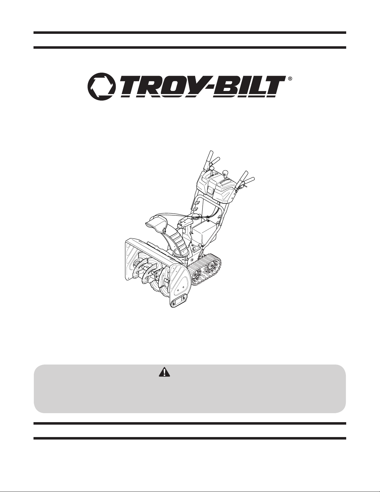
Snow Tracker 2690
WARNING
READ AND FOLLOW ALL SAFETY RULES AND INSTRUCTIONS IN THIS MANUAL
BEFORE ATTEMPTING TO OPERATE THIS MACHINE.
FAILURE TO COMPLY WITH THESE INSTRUCTIONS MAY RESULT IN PERSONAL INJURY.
TROY-BILT LLC, P.O. BOX 361131 CLEVELAND, OHIO 44136-0019
Printed In USA
Form No. 769-04054
(April 28, 2007)
Page 2

To The Owner
Thank You
Thank you for purchasing a Snow Thrower manufactured by
Troy-Bilt LLC. It was carefully engineered to provide excellent
performance when properly operated and maintained.
Please read this entire manual prior to operating the equipment.
It instructs you how to safely and easily set up, operate and
maintain your machine. Please be sure that you, and any other
persons who will operate the machine, carefully follow the
recommended safety practices at all times. Failure to do so could
result in personal injury or property damage.
All information in this manual is relative to the most recent
product information available at the time of printing. Review
this manual frequently to familiarize yourself with the machine,
its features and operation. Please be aware that this Operator’s
Manual may cover a range of product specifications for various
models. Characteristics and features discussed and/or illustrated
in this manual may not be applicable to all models. Troy-Bilt LLC
reserves the right to change product specifications, designs and
equipment without notice and without incurring obligation.
Table of Contents
Safe Operation Practices ........................................ 3
Assembly & Set-Up .................................................. 7
Controls ...................................................................12
Operation ................................................................15
Maintenance & Adjustment..................................17
1
If you have any problems or questions concerning the machine,
phone a authorized Troy-Bilt service dealer or contact us directly.
Troy-Bilt’s Customer Support telephone numbers, website
address and mailing address can be found on this page. We want
to ensure your complete satisfaction at all times.
Throughout this manual, all references to right and left side of the
machine are observed from the operating position
Engine Maintenance ............................................. 20
Service .................................................................... 23
Troubleshooting .................................................... 27
Replacement Parts ................................................ 28
Warranty ..................................................Back Cover
Record Product Information
Before setting up and operating your new equipment, please
locate the model plate on the equipment and record the
information in the provided area to the right. You can locate the
model plate by standing at the operator’s position and looking
down at the rear of the frame. This information will be necessary,
should you seek technical support via our web site, Customer
Support Department, or with a local authorized service dealer.
MO d e l nu M b e r
se r i a l nu M b e r
Customer Support
Please do NOT return the machine to the retailer or dealer without first contacting our Customer Support Department.
If you have difficulty assembling this product or have any questions regarding the controls, operation, or maintenance of
this machine, you can seek help from the experts. Choose from the options below:
Visit us on the web at www.troybilt.com◊
Call a Customer Support Representative at (800) 828-5500 or (330) 558-7220◊
Write us at Troy-Bilt LLC • P.O. Box 361131 • Cleveland, OH • 44136-0019◊
2
Page 3
Important Safe Operation Practices
WARNING! This symbol points out important safety instructions which, if not followed,
could endanger the personal safety and/or property of yourself and others. Read and follow
all instructions in this manual before attempting to operate this machine. Failure to comply
with these instructions may result in personal injury.
When you see this symbol. HEED ITS WARNING!
CALIfORNIA PROPOSITION 65
WARNING! Engine Exhaust, some of its constituents, and certain vehicle components
contain or emit chemicals known to State of California to cause cancer and birth defects
or other reproductive harm.
DANGER: This machine was built to be operated according to the safe operation practices in
this manual. As with any type of power equipment, carelessness or error on the part of the
operator can result in serious injury. This machine is capable of amputating fingers, hands,
toes and feet and throwing foreign objects. Failure to observe the following safety
instructions could result in serious injury or death.
2
Training
Read, understand, and follow all instructions on the 1.
machine and in the manual(s) before attempting to
assemble and operate. Keep this manual in a safe place for
future and regular reference and for ordering replacement
parts.
Be familiar with all controls and their proper operation. 2.
Know how to stop the machine and disengage them
quick ly.
Never allow children under 14 years of age to operate this 3.
machine. Children 14 and over should read and understand
the instructions and safe operation practices in this manual
and on the machine and be trained and supervised by an
adult.
Never allow adults to operate this machine without proper 4.
instruction.
Thrown objects can cause serious personal injury. Plan 5.
your snow-throwing pattern to avoid discharge of material
toward roads, bystanders and the like.
Keep bystanders, pets and children at least 75 feet from the 6.
machine while it is in operation. Stop machine if anyone
enters the area.
Exercise caution to avoid slipping or falling, especially 7.
when operating in reverse.
Preparation
Thoroughly inspect the area where the equipment is to be used.
Remove all doormats, newspapers, sleds, boards, wires and other
foreign objects, which could be tripped over or thrown by the
auger/impeller.
Always wear safety glasses or eye shields during operation 1.
and while performing an adjustment or repair to protect
your eyes. Thrown objects which ricochet can cause serious
injury to the eyes.
Do not operate without wearing adequate winter outer 2.
garments. Do not wear jewelry, long scarves or other loose
clothing, which could become entangled in moving parts.
Wear footwear which will improve footing on slippery
surfaces.
Use a grounded three-wire extension cord and receptacle 3.
for all machines with electric start engines.
Adjust collector housing height to clear gravel or crushed 4.
rock surfaces.
Disengage all control levers before starting the engine. 5.
Never attempt to make any adjustments while engine is 6.
running, except where specifically recommended in the
operator’s manual.
Let engine and machine adjust to outdoor temperature 7.
before starting to clear snow.
3
Page 4

Safe Handling of Gasoline
To avoid personal injury or property damage use extreme care
in handling gasoline. Gasoline is extremely flammable and the
vapors are explosive. Serious personal injury can occur when
gasoline is spilled on yourself or your clothes which can ignite.
Wash your skin and change clothes immediately.
Use only an approved gasoline container.a.
Extinguish all cigarettes, cigars, pipes and other b.
sources of ignition.
Never fuel machine indoors. c.
Never remove gas cap or add fuel while the engine is d.
hot or running.
Allow engine to cool at least two minutes before e.
refueling.
Never over fill fuel tank. Fill tank to no more than ½ f.
inch below bottom of filler neck to provide space for
fuel expansion.
Replace gasoline cap and tighten securely.g.
If gasoline is spilled, wipe it off the engine and h.
equipment. Move machine to another area. Wait 5
minutes before starting the engine.
Never store the machine or fuel container inside i.
where there is an open flame, spark or pilot light
(e.g. furnace, water heater, space heater, clothes
dryer etc.).
Allow machine to cool at least 5 minutes before j.
storing.
Never fill containers inside a vehicle or on a truck k.
or trailer bed with a plastic liner. Always place
containers on the ground away from your vehicle
before filling.
If possible, remove gas-powered equipment from l.
the truck or trailer and refuel it on the ground. If this
is not possible, then refuel such equipment on a
trailer with a portable container, rather than from a
gasoline dispenser nozzle.
Keep the nozzle in contact with the rim of the fuel m.
tank or container opening at all times until fueling is
complete. Do not use a nozzle lock-open device.
Operation
Do not put hands or feet near rotating parts, in the auger/1.
impeller housing or chute assembly. Contact with the
rotating parts can amputate hands and feet.
The auger/impeller control lever is a safety device. Never 2.
bypass its operation. Doing so makes the machine unsafe
and may cause personal injury.
The control levers must operate easily in both directions 3.
and automatically return to the disengaged position when
released.
Never operate with a missing or damaged chute assembly. 4.
Keep all safety devices in place and working.
Never run an engine indoors or in a poorly ventilated area. 5.
Engine exhaust contains carbon monoxide, an odorless
and deadly gas.
Do not operate machine while under the influence of 6.
alcohol or drugs.
Muffler and engine become hot and can cause a burn. Do 7.
not touch. Keep children away.
Exercise extreme caution when operating on or crossing 8.
gravel surfaces. Stay alert for hidden hazards or traffic.
Exercise caution when changing direction and while 9.
operating on slopes.
Plan your snow-throwing pattern to avoid discharge 10.
towards windows, walls, cars etc. Thus, avoiding possible
property damage or personal injury caused by a ricochet.
Never direct discharge at children, bystanders and pets or 11.
allow anyone in front of the machine.
Do not overload machine capacity by attempting to clear 12.
snow at too fast of a rate.
Never operate this machine without good visibility or light. 13.
Always be sure of your footing and keep a firm hold on the
handles. Walk, never run.
Disengage power to the auger/impeller when transporting 14.
or not in use.
Never operate machine at high transport speeds on 15.
slippery surfaces. Look down and behind and use care
when backing up.
If the machine should start to vibrate abnormally, stop 16.
the engine, disconnect the spark plug wire and ground it
against the engine. Inspect thoroughly for damage. Repair
any damage before starting and operating.
Disengage all control levers and stop engine before you 17.
leave the operating position (behind the handles). Wait
until the auger/impeller comes to a complete stop before
unclogging the chute assembly, making any adjustments,
or inspections.
Never put your hand in the discharge or collector 18.
openings. Always use the clean-out tool provided to
unclog the discharge opening. Do not unclog chute
assembly while engine is running. Shut off engine and
remain behind handles until all moving parts have stopped
before unclogging.
Use only attachments and accessories approved by the 19.
manufacturer (e.g. wheel weights, tire chains, cabs etc.).
When starting engine, pull cord slowly until resistance 20.
is felt, then pull rapidly. Rapid retraction of starter cord
(kickback) will pull hand and arm toward engine faster than
you can let go. Broken bones, fractures, bruises or sprains
could result.
If situations occur which are not covered in this manual, use 21.
care and good judgment. Contact Customer Support for
assistance and the name of your nearest servicing dealer.
4 se c t i O n 2 — iM p O r t a n t sa f e Op e r a t i O n pr a c t i c e s
Page 5

Maintenance & Storage
Never tamper with safety devices. Check their proper 1.
operation regularly. Refer to the maintenance and
adjustment sections of this manual.
Before cleaning, repairing, or inspecting machine 2.
disengage all control levers and stop the engine. Wait until
the auger/impeller come to a complete stop. Disconnect
the spark plug wire and ground against the engine to
prevent unintended starting.
Check bolts and screws for proper tightness at frequent 3.
intervals to keep the machine in safe working condition.
Also, visually inspect machine for any damage.
Do not change the engine governor setting or over-speed 4.
the engine. The governor controls the maximum safe
operating speed of the engine.
Snow thrower shave plates and skid shoes are subject to 5.
wear and damage. For your safety protection, frequently
check all components and replace with original equipment
manufacturer’s (OEM) parts only. “Use of parts which do
not meet the original equipment specifications may lead to
improper performance and compromise safety!”
Check control levers periodically to verify they engage 6.
and disengage properly and adjust, if necessary. Refer
to the adjustment section in this operator’s manual for
instructions.
Maintain or replace safety and instruction labels, as 7.
necessa ry.
Observe proper disposal laws and regulations for gas, oil, 8.
etc. to protect the environment.
Prior to storing, run machine a few minutes to clear snow 9.
from machine and prevent freeze up of auger/impeller.
Never store the machine or fuel container inside where 10.
there is an open flame, spark or pilot light such as a water
heater, furnace, clothes dryer etc.
Always refer to the operator’s manual for proper 11.
instructions on off-season storage.
Check fuel line, tank, cap, and fittings frequently for cracks 12.
or leaks. Replace if necessary.
Do not crank engine with spark plug removed.13.
According to the Consumer Products Safety Commission 14.
(CPSC) and the U.S. Environmental Protection Agency (EPA),
this product has an Average Useful Life of seven (7) years,
or 60 hours of operation. At the end of the Average Useful
Life have the machine inspected annually by an authorized
service dealer to ensure that all mechanical and safety
systems are working properly and not worn excessively.
Failure to do so can result in accidents, injuries or death.
Do not modify engine
To avoid serious injury or death, do not modify engine in any
way. Tampering with the governor setting can lead to a runaway
engine and cause it to operate at unsafe speeds. Never tamper
with factory setting of engine governor.
Notice Regarding Emissions
Engines which are certified to comply with California and federal
EPA emission regulations for SORE (Small Off Road Equipment)
are certified to operate on regular unleaded gasoline, and
may include the following emission control systems: Engine
Modification (EM), Oxidizing Catalyst (OC), Secondary Air
Injection (SAI) and Three Way Catalyst (TWC) if so equipped.
Spark Arrestor
WARNING! This machine is equipped with an
internal combustion engine and should not be used
on or near any unimproved forest-covered, brush
covered or grass-covered land unless the engine’s
exhaust system is equipped with a spark arrester
meeting applicable local or state laws (if any).
If a spark arrester is used, it should be maintained in effective
working order by the operator. In the State of California the
above is required by law (Section 4442 of the California Public
Resources Code). Other states may have similar laws. Federal laws
apply on federal lands.
A spark arrester for the muffler is available through your
nearest engine authorized service dealer or contact the service
department, P.O. Box 361131 Cleveland, Ohio 44136-0019.
5se c t i O n 2 — iM p O r t a n t sa f e Op e r a t i O n pr a c t i c e s
Page 6
Safety Symbols
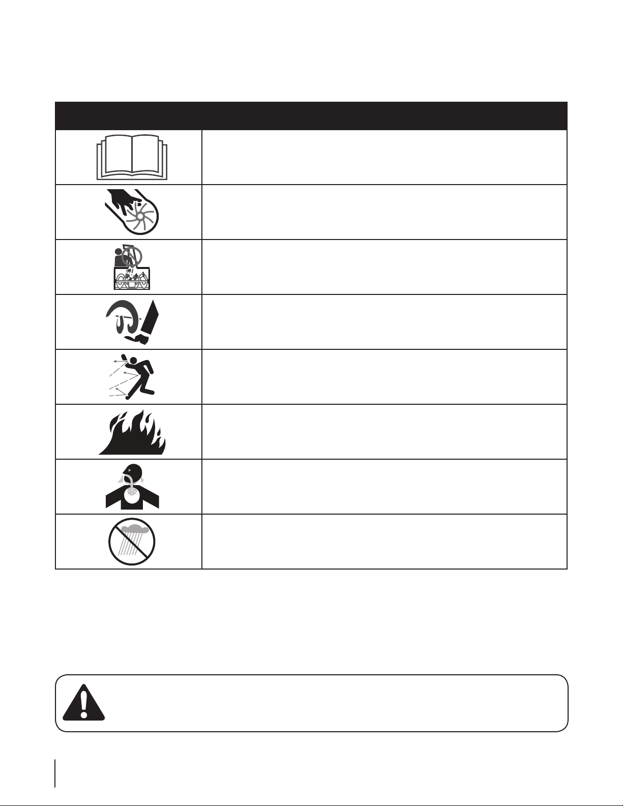
This page depicts and describes safety symbols that may appear on this product. Read, understand, and follow all instructions on the
machine before attempting to assemble and operate.
Symbol Description
READ THE OPERATOR’S MANUAL(S)
Read, understand, and follow all instructions in the manual(s) before attempting to
assemble and operate
WARNING— ROTATING BLADES
Keep hands out of inlet and discharge openings while machine is running. There are rotating
blades inside
WARNING— ROTATING BLADES
Keep hands out of inlet and discharge openings while machine is running. There are rotating
blades inside
WARNING— ROTATING AUGER
Do not put hands or feet near rotating parts, in the auger/impeller housing or chute
assembly. Contact with the rotating parts can amputate hands and feet.
WARNING—THROWN OBJECTS
This machine may pick up and throw and objects which can cause serious personal injury.
WARNING—GASOLINE IS FLAMMABLE
Allow the engine to cool at least two minutes before refueling.
WARNING— CARBON MONOXIDE
Never run an engine indoors or in a poorly ventilated area. Engine exhaust contains carbon
monoxide, an odorless and deadly gas.
WARNING— ELECTRICAL SHOCK
Do not use the engine’s electric starter in the rain
WARNING! Your Responsibility—Restrict the use of this power machine to persons who read, understand and
follow the warnings and instructions in this manual and on the machine.
6 se c t i O n 2 — iM p O r t a n t sa f e Op e r a t i O n pr a c t i c e s
SAVE THESE INSTRUCTIONS!
Page 7
1
1
2
Assembly & Set-Up
Contents of Carton
Two Ignition Keys• One Snow Thrower• One Chute Assembly•
One 110V Extension Cord• One Snow Thrower Operator’s •
Manual
3
Assembly
Handle
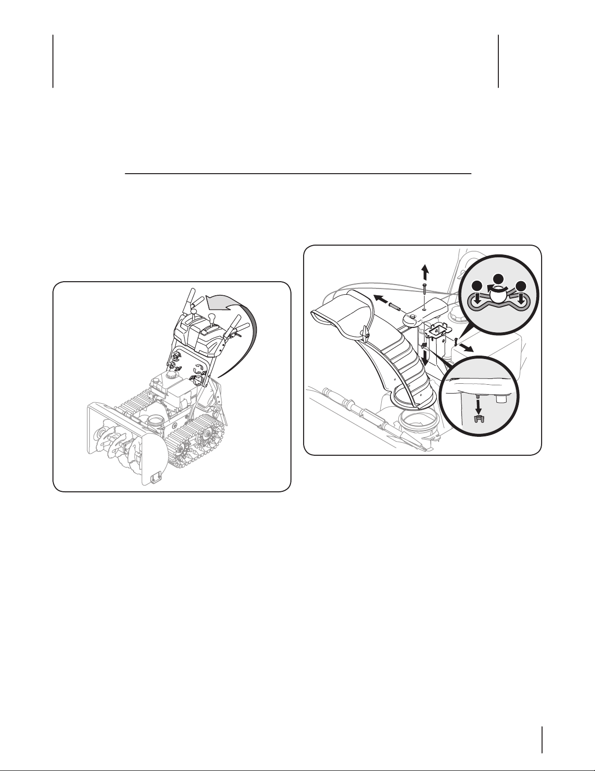
Place the shift lever in the Forward-6 position1.
Remove the lower plastic wing nut and carriage bolt from 2.
each side of the upper handle; then raise the upper handle
assembly until it snaps over the lower handle. See Figure
3-1 .
Chute Assembly
Remove wing nut and hex screw from chute control 1.
assembly and clevis pin and cotter pin from chute support
bracket. Position the chute assembly (forward-facing) over
the chute base. See Fig. 3-2.
Figure 3-2
Figure 3-1
Looking beneath the handle panel, check that all of the 3.
cables (steering, auger, shift, and drive) are properly routed
and not pinched or kinked.
NOTE: Make certain the upper ends of each cable are
seated properly in the proper brackets.
Secure the handle by tightening the plastic knob located 4.
on both the left and right sides of the handle. Remove
and discard any rubber bands, if present. They are for
packaging purposes only.
7
Page 8
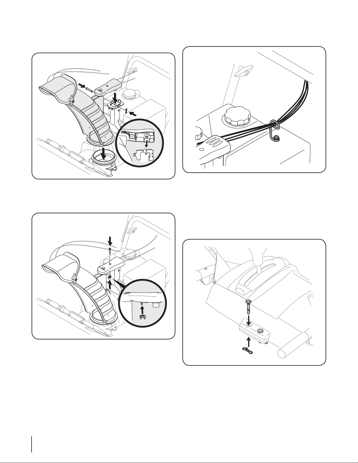
Place chute assembly onto chute base and secure chute 2.
control assembly to chute support bracket with clevis pin
and cotter pin removed earlier. See See Fig. 3-3.
Figure 3-3
Finish securing chute control assembly to chute support 3.
bracket with wing nut and hex screw removed earlier.
See Fig. 3-4.
Check that all cables are properly routed through the cable 4.
guide on top of the engine. See Fig. 3-5.
Figure 3-5
Set-Up
Shear Pins
A pair of replacement auger shear pins and bow tie cotter pins
are included with your snow thrower. Store them in your snow
thrower’s dash panel until needed. See Fig. 3-6.
Figure 3-4
8 se c t i O n 2— as s e M b l y & se t -up
Figure 3-6
Page 9
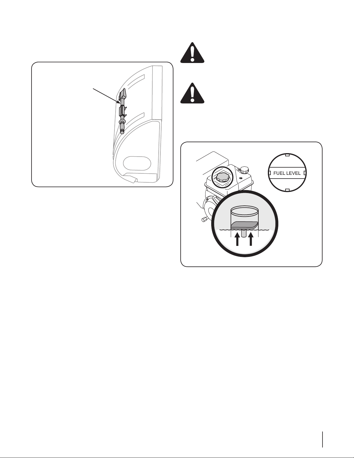
Chute Clean-Out Tool
Chute Clean-Out Tool
Fuel Level Indicator
Top View
The chute clean-out tool is fastened to the top of the auger
housing with a mounting clip and a cable tie at the factory. Cut
the cable tie before operating the snow thrower. See Fig. 3-7.
Figure 3-7
Adding Fuel
WARNING! Use extreme care when handling
gasoline. Gasoline is extremely flammable and the
vapors are explosive. Never fuel the machine
indoors or while the engine is hot or running.
Extinguish cigarettes, cigars, pipes and other
sources of ignition.
WARNING! Always keep hands and feet clear of
the equipment’s moving parts. Do not use a
pressurized starting fluid. Vapors are flammable.
Clean around the fuel fill before removing the cap to fuel.1.
A fuel level indicator is located in the fuel tank. Fill the tank 2.
until the fuel reaches the fuel level indictor, Fig. 3-8. Be
careful not to overfill.
Fuel Recommendations
Use automotive gasoline (unleaded or low leaded to minimize
combustion chamber deposits) with a minimum of 87 octane.
Gasoline with up to 10% ethanol or 15% MTBE (Methyl Tertiary
Butyl Ether) can be used. Never use an oil/gasoline mixture or
dirty gasoline. Avoid getting dirt, dust, or water in the fuel tank.
DO NOT use E85 gasoline.
Refuel in a well-ventilated area with the engine stopped. •
Do not smoke or allow flames or sparks in the area where
the engine is refueled or where gasoline is stored.
Do not overfill the fuel tank. After refueling, make sure the •
tank cap is closed properly and securely.
Be careful not to spill fuel when refueling. Spilled fuel or •
fuel vapor may ignite. If any fuel is spilled, make sure the
area is dry before starting the engine.
Avoid repeated or prolonged contact with skin or •
breathing of vapor.
Figure 3-8
9se c t i O n 2 — as s e M b l y & se t -up
Page 10
Checking Oil Level
Fill
between
high
and low
marks
CAUTION: The engine is shipped with oil in the
engine. You must, however, check the oil level prior
to operating the snow thrower. Running the engine
with insufficient oil can cause serious engine
damage and void the engine warranty.
NOTE: Be sure to check the engine on a level surface with the
engine stopped.
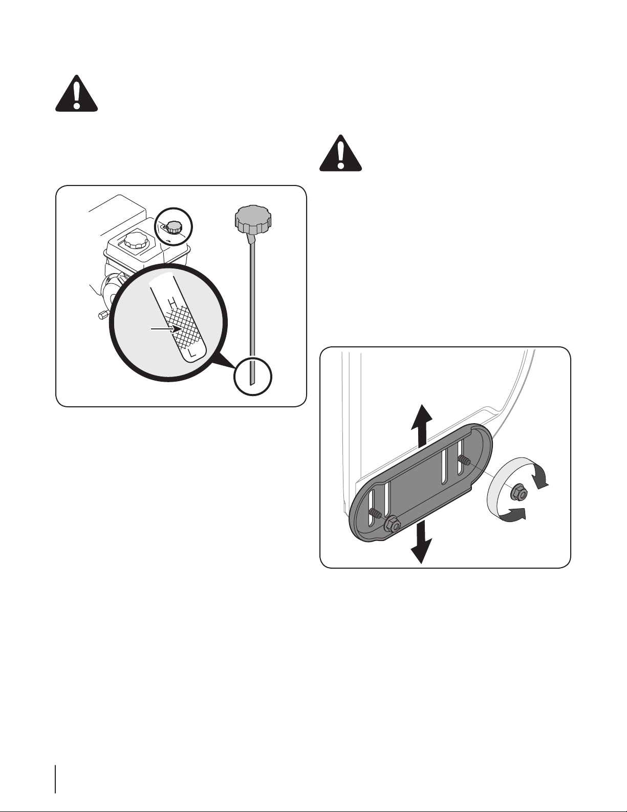
Remove the oil filler cap/dipstick and wipe the dipstick 1.
clean. See Fig. 3-9.
Adjustments
Skid Shoes
The snow thrower skid shoes are adjusted upward at the factory
for shipping purposes. Adjust them downward, if desired, prior
to operating the snow thrower.
CAUTION: It is not recommended that you operate
this snow thrower on gravel as it can easily pick up
and throw loose gravel, causing personal injury or
damage to the snow thrower and surrounding
property.
For close snow removal on a smooth surface, raise the skid shoes
higher on the auger housing.
Use a middle or lower position when the area to be cleared is
uneven, such as a gravel driveway
NOTE: If you choose to operate the snow thrower on
a gravel surface, keep the skid shoes in position for
maximum clearance between the ground and the shave
plate.
To adjust the skid shoes:
Loosen the four hex nuts (two on each side) and carriage 1.
bolts. Move the skid shoes to the desired position. See Fig.
3-1 0.
Figure 3-9
Insert the cap/dipstick into the oil filler neck, but do 2. not
screw it in.
Remove the oil filler cap/dipstick. If the level is low, slowly 3.
add oil until the oil level registers between high (H) and low
(L), Fig. 3-9. Refer to the Engine Maintenance section for
the correct oil viscosity and engine oil capacity.
NOTE: Do not overfill. Overfilling with oil may result in
engine smoking, hard starting or spark plug fouling.
Replace and tighten the cap/dipstick firmly before starting 4.
the engine.
Figure 3-10
Make certain the entire bottom surface of the skid shoe is 2.
against the ground to avoid uneven wear on the skid shoes.
Retighten the nuts and bolts securely.3.
10 se c t i O n 2— as s e M b l y & se t -up
Page 11
Auger Control
“J” Bolt
Flange Lock Nut
Track Side Plate
WARNING! Prior to operating your snow thrower,
carefully read and follow all the instructions below.
Perform all adjustments to verify your snow thrower
is operating safely and properly.
Check the adjustment of the auger control as follows:
When the auger control is released and in the disengaged 1.
“up” position, the cable should have very little slack. It
should NOT be tight.
In a well-ventilated area, start the snow thrower engine. 2.
Refer to Starting the Engine on page 15. Make sure the
throttle is set in the FAST position.
While standing in the operator’s position (behind the snow 3.
thrower), engage the auger.
Allow the auger to remain engaged for approximately ten 4.
(10) seconds before releasing the auger control. Repeat this
several times.
With the throttle control in the FAST (rabbit) position and 5.
the auger control in the disengaged “up” position, walk to
the front of the machine.
Confirm that the auger has completely stopped rotating 6.
and shows NO signs of motion.
IMPORTANT: If the auger shows ANY signs of rotating,
immediately return to the operator’s position and shut off the
engine. Wait for ALL moving parts to stop before readjusting the
auger control.
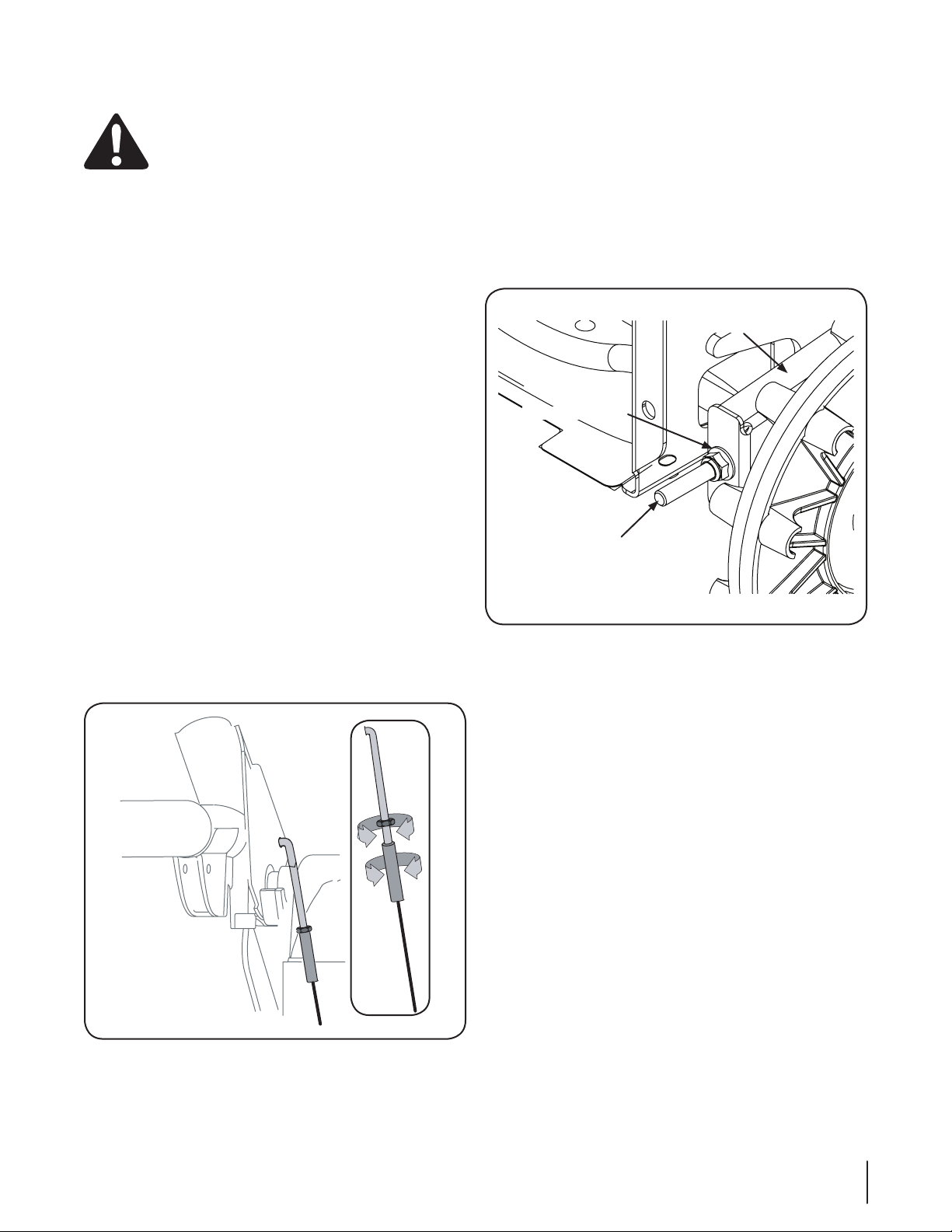
To readjust the control cable, loosen the hex jam nut on the 7.
auger control cable “Z” fitting.
Thread the ferrule without turning the cable onto the “Z” 8.
fitting until there is no slack in the cable. See Fig. 3-11. Do
not overtighten the cable. Hold the flats on the ferrule with
pliers and tighten the jam nut against the ferrule.
Rotate the coupling end of the cable counterclockwise to 9.
provide more slack.
Retighten the hex jam nut. See Fig. 3-11.10.
Repeat Auger Control Test to verify proper adjustment has 11.
been achieved.
Track Tension
Over time the track can stretch. To adjust the track tension turn
the flange lock nut on the front of the track side plate. This pulls
the “J” bolts attached to the axle and tightens the tracks. See Fig.
3-12.
Figure 3-12
Figure 3-11
11se c t i O n 2 — as s e M b l y & se t -up
Page 12
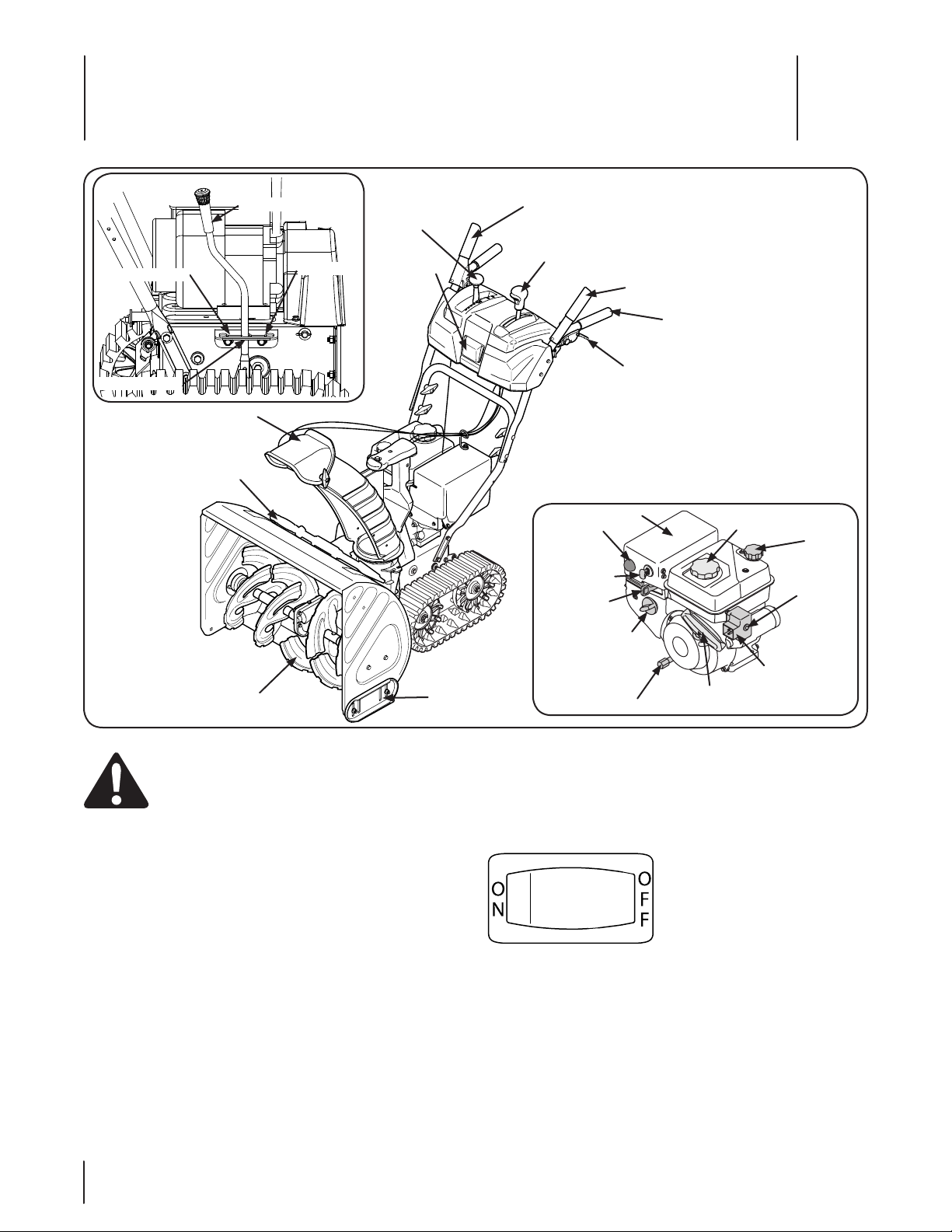
Ignition Key
Oil Fill
Primer
Gasoline
Cap
Electric
Starter
Outlet
Recoil
Starter
Oil Drain
Choke
Control
Throttle
Control
Electric
Starter
Button
Muffler
Track Drive
Control/Auger
Control Lock
Headlight
Chute Assembly
Chute
Cleanout
Tool
Auger
Skid Shoe
Shift Lever
Chute Directional Control
Auger Control
Track Steering Control
Heated Grips
Track Lock Lever
Normal Snow
Packed Snow
Transport
Controls and Features
4
12
WARNING! Read, understand, and follow all
instructions and warnings on the machine and in
this manual before operating.
Figure 4-1
Shift Lever
The shift lever is located in the right side of the handle panel and
is used to determine both the ground speed and direction of
travel. It can be moved into any of eight positions.
Forward
Your snow thrower has six forward (F) speeds, with position
number one (1) being the slowest.
Reverse
Your snow thrower has two reverse (R) speeds, with position
number one (1) being the slowest.
NOTE: Always release the drive control before changing
speeds.
Headlight
The headlight is on whenever the engine is running.
Heated Grip
To activate the heated grips, move the switch found on the rear
of the dash panel into the ON position.
Skid Shoe
The space between the shave plate and the ground can be
adjusted by positioning the skid shoes. Refer to Skid Shoe
Adjustment on page 10.
Page 13
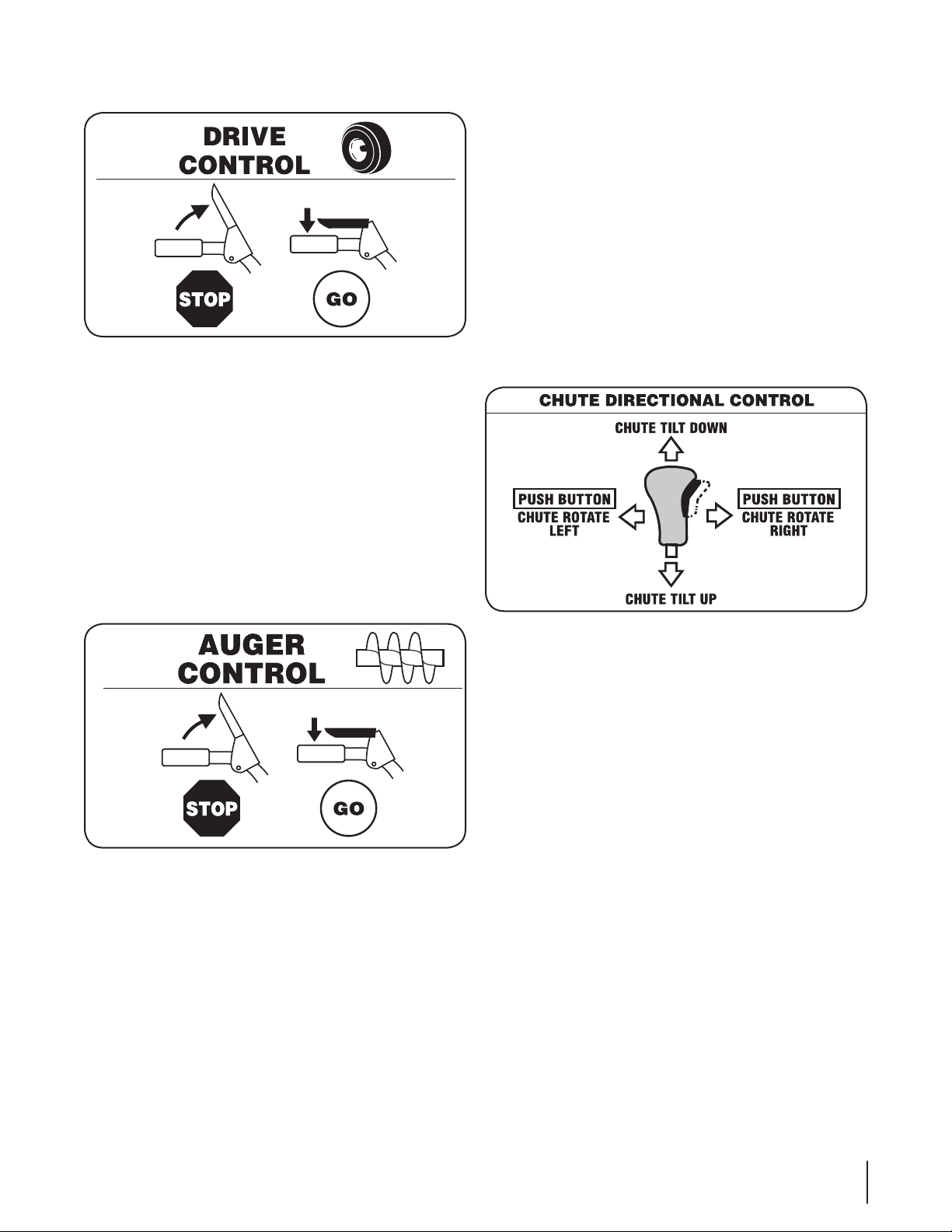
Track Drive Control / Auger Clutch Lock*
The track drive control is located on the right handle. Squeeze
the control grip against the handle to engage the track drive.
Release to stop.
Note: Always release the drive control before changing speeds.
Failure to do so will result in increased wear on your machine’s
drive system.
*On this model, the drive control also locks the auger control
so that you can operate the chute control handle without
interrupting the snow throwing process. If the auger control is
engaged simultaneously with the drive control, the operator can
release the auger control (on the left handle) and the augers will
remain engaged. Release both controls to stop the augers and
the wheel drive.
Skid Shoes
Position the skid shoes based on surface conditions. Adjust
upward for hard-packed snow. Adjust downward when
operating on gravel or crushed rock surfaces.
Track Steering Controls
The left and right track steering controls are located on the
underside of the handles and they are used to assist in steering
the snow thrower. Squeeze the right track control when turning
right, squeeze the left control when turning left. Operate your
snow thrower in open areas until you become familiar with these
controls.
NOTE: It is easier to maneuver a non-running snow thrower
with both track steering controls held in simultaneously.
Chute Directional Control
Auger Control
The auger control is located on the left handle. Squeeze the
control grip against the handle to engage the augers and start
snow throwing action. Release to stop.
Augers
When engaged, the augers rotate and draw snow into the auger
housing.
Chute Assembly
Snow drawn into the auger housing is discharged out the chute
assembly.
Recoil Starter Handle
This handle is used to manually start the engine.
The chute directional control is located on the left side of the
dash panel.
To change the direction in which snow is thrown, squeeze •
the button on the joy-stick and pivot the joy-stick to the
right or to the left.
To change the angle/distance which snow is thrown, pivot •
the joy-stick forward or backward.
Track Lock Lever
The track lock lever is located on the right side of the snow
thrower and is used to select the position of the auger housing
and the method of track operation. Move the lever to the right,
then forward or backward to one of the three positions.
Transport
Raises the front end of the snow thrower for easy transport.
Using proper caution, this position may also be used on many
gravel driveways to clear snow while leaving gravel undisturbed.
Normal Snow
Allows the tracks to be suspended independently for continuous
ground contact.
Packed Snow
Locks the front end of the snow thrower down to the ground for
hard-packed or icy snow conditions.
13se c t i O n 4 — cO n t r O l s a n d fe a t u r e s
Page 14
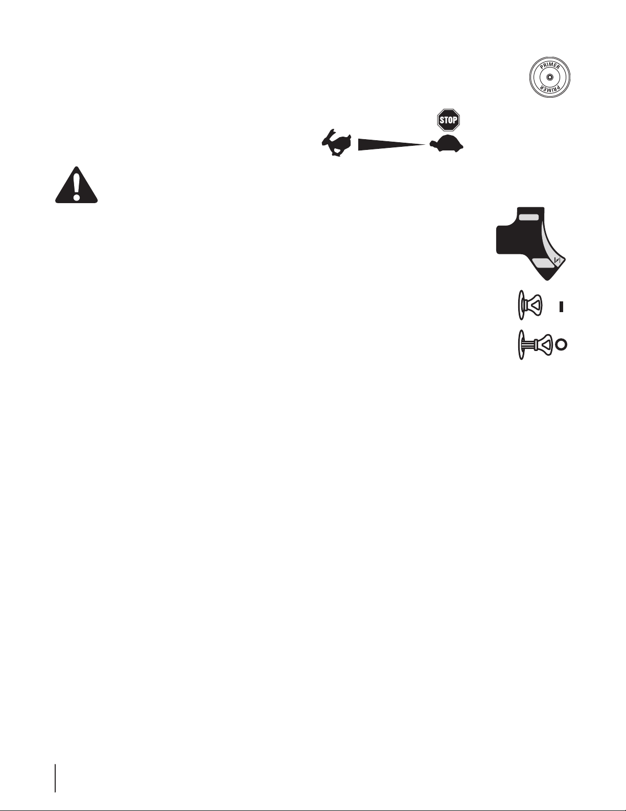
Oil Fill
RUN
MAR CHE
CHOKE
VOLET DE
DÉPART
Engine oil level can be checked and oil added through the oil fill.
Oil Drain
Engine oil can be drained through the oil drain.
Muffler
Engine exhaust exists the engine via the muffler.
WARNING! Do not touch the muffler while the
engine is hot or running. The muffler is hot and can
cause a severe burn.
Electric Starter Outlet
Requires the use of a three-prong outdoor extension cord and a
120V power source/wall outlet.
NOTE: The electric starter is mounted to the plastic shroud and is
shown in Fig. 4-1 attached to the engine for easier reference.
Primer
Pressing the primer forces fuel directly into the
engine’s carburetor to aid in cold-weather starting.
Throttle Control
The throttle control is located on the engine. It regulates the
speed of the engine and will shut off the engine when pushed
into the stop position.
Choke Control
The choke control is found on the rear fo
the engine and is activated by rotating the
knob clockwise. Activating the choke control
closes the choke plate on the carburetor and
aids in starting the engine.
Electric Starter Button
Pressing the electric starter button engages the engine’s electric
starter when plugged into a 120V power source.
Gas Cap
Unthread the gas cap to add gasoline to the fuel tank.
Ignition Key
The safety ignition key must be fully inserted
and snapped in place before the engine will
start. Remove the ignition key to prevent any
unauthorized use of the equipment.
NOTE: Do NOT attempt to turn the key.
14 se c t i O n 4 — cO n t r O l s a n d fe a t u r e s
Page 15
Operation
5
Starting the Engine
WARNING! Always keep hands and feet clear of
moving parts. Do not use a pressurized starting
fluid. Vapors are flammable.
NOTE: Allow the engine to warm up for a few minutes after
starting. The engine will not develop full power until it reaches
operating temperatures.
Electric Starter
WARNING! The electric starter is equipped with a
grounded three-wire power cord and plug, and is
designed to operate on 120 volt AC household
current. It must be used with a properly grounded
three-prong receptacle at all times to avoid the
possibility of electric shock. Follow all instructions
carefully prior to operating the electric starter.
DO NOT use the electric starter in rain.
Determine that your home’s wiring is a three-wire 1.
grounded system. Ask a licensed electrician if you are
unsure. If you have a grounded three-prong receptacle,
proceed as follows. If you do not have the proper house
wiring, DO NOT use the electric starter under any
conditions.
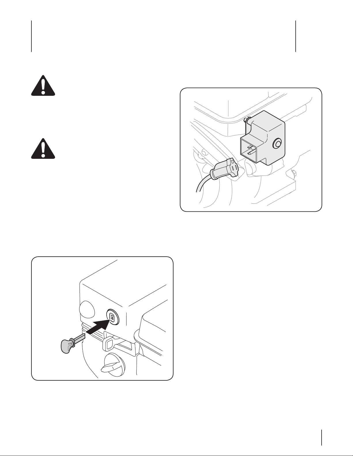
Insert the ignition key fully into the slot, Fig. 5-1. Make 2.
sure it snaps into place. DO NOT turn the ignition key. The
engine cannot start unless the key is inserted into the
ignition switch.
Figure 5-1
Plug the extension cord into the electric outlet located on 3.
the plastic shroud. Plug the other end of extension cord
into a three-prong 120-volt, grounded, AC outlet in a well-
ventilated area. See Fig. 5-2.
Figure 5-2
Move the throttle control to the FAST (rabbit) position.4.
Move the choke to the ON position (cold engine start). If 5.
the engine is warm, place the choke in the OFF position.
Push the primer three to five (3-5) times, making sure to 6.
cover the vent hole when pushing. If the engine is warm,
push the primer only once. Always cover the vent hole
when pushing. Cool weather may require priming to be
repeated.
Push the starter button to start the engine. 7. Once the
engine starts, immediately release the starter button.
The electric starter is equipped with thermal overload
protection; the system will temporarily shut-down to
allow the starter to cool if the electric starter becomes
overloaded.
As the engine warms, slowly rotate the choke control to 8.
the OFF position. If the engine falters, restart the engine
and run with the choke at half-choke position for a short
period of time, and then slowly rotate the choke into the
OFF position.
After the engine is running, disconnect the power cord 9.
from the electric starter. When disconnecting, always
unplug the end at the wall outlet before unplugging the
opposite end from the engine.
15
Page 16

Recoil Starter
CAUTION! Do not pull the starter handle while the
engine running.
WARNING! To avoid unsupervised engine
operation, never leave the engine unattended while
running. Turn the engine off after use and remove
ignition key
Insert the ignition key fully into the slot, Fig. 5-1. Make 1.
sure it snaps into place. DO NOT turn the ignition key. The
engine cannot start unless the key is inserted into the
ignition switch.
Move the throttle control to the FAST (rabbit) position.2.
Move the choke to the ON position (cold engine start). If 3.
the engine is warm, place the choke in the OFF position.
Push the primer three to five (3-5) times, making sure to 4.
cover the vent hole when pushing. If the engine is warm,
push the primer only once. Always cover the vent hole
when pushing. Cool weather may require priming to be
repeated.
Pull gently on the starter handle until it begins to 5.
resist, then pull quickly and forcefully to overcome the
compression. Do not release the handle and allow it to
snap back. Return the rope SLOWLY to the original position.
If required, repeat this step.
WARNING! Rapid retraction of the starter cord
(kickback) will pull your hand and arm toward
engine faster than you can let go. Broken bones,
fractures, bruises or sprains could result.
As the engine warms, slowly rotate the choke control to the 6.
OFF position. If the engine falters, restart the engine and
run with the choke at the half-choke position for a short
period of time, and then slowly rotate the choke into OFF
position.
To Engage Drive
With the throttle control in the Fast (rabbit) position, move 1.
the shift lever into one of the six forward (F) positions or
two reverse (R) positions. Select a speed appropriate for
the snow conditions and a pace you are comfortable with.
Squeeze the drive control against the handle and the snow 2.
thrower will move. Release it and the drive motion will
stop.
To Engage Augers
To engage the augers and start throwing snow, squeeze 1.
the auger control against the left handle. Release to stop
the augers.
Stopping the Engine
WARNING! To avoid unsupervised engine
operation, never leave the machine unattended
with the engine running. Turn the engine off after
use and remove the ignition key
Run the engine for a few minutes before stopping to help dry off
any moisture on the engine.
Move the throttle control to the STOP position.1.
Remove the ignition key. Removing the key will reduce the 2.
possibility of any unauthorized starting of the engine while
the equipment is not in use. Keep the key in a safe place.
The engine cannot start without the ignition key.
Wipe any moisture away from the controls on the engine.3.
16 se c t i O n 5— Op e r a t i O n
Page 17
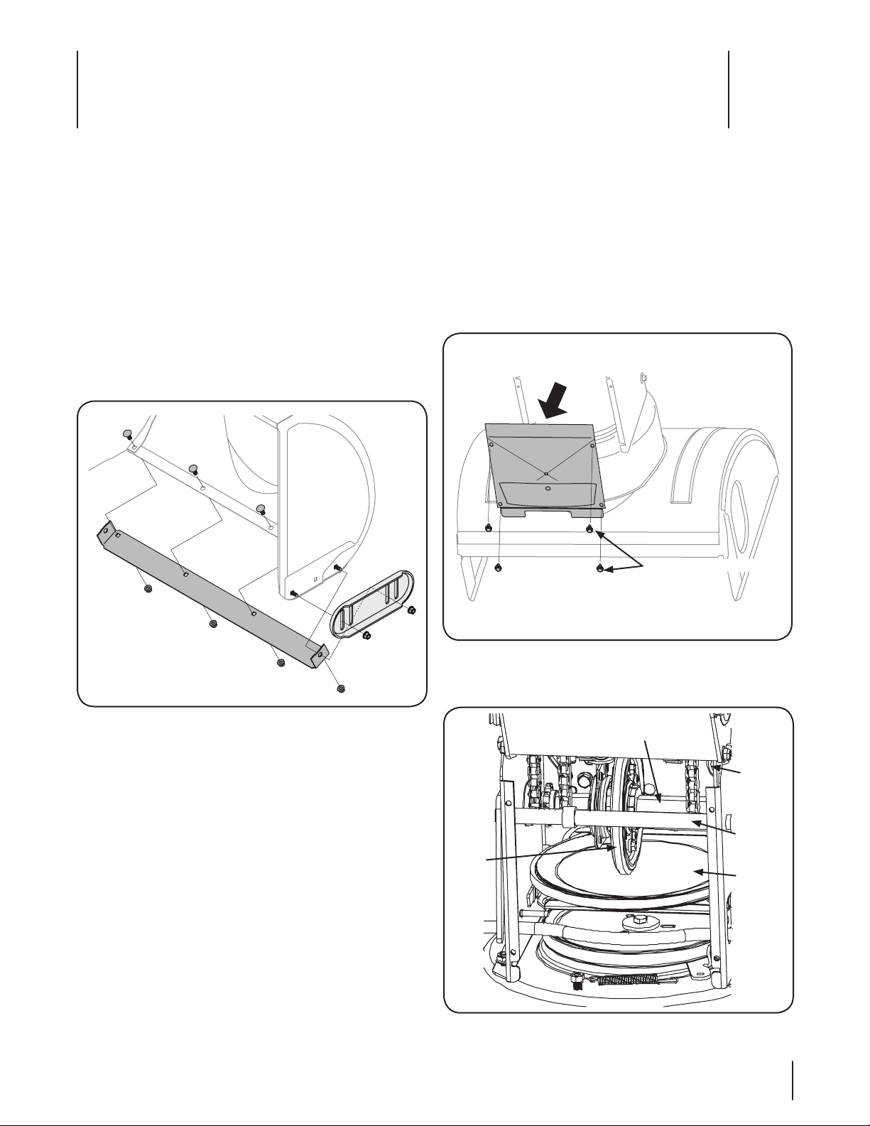
Self-Tapping Screws
Gear Shaft
friction
Wheel
Rubber
Drive
Cable
Pivot Rod
Drive
Plate
Maintenance & Adjustments
6
Maintenance
Engine
Refer to the Engine Maintenance section.
Shave Plate and Skid Shoes
The shave plate and skid shoes on the bottom of the snow
thrower are subject to wear. They should be checked periodically
and replaced when necessary.
To remove the skid shoes:
Remove the four carriage bolts and hex flange nuts which 1.
secure them to the snow thrower.
Reassemble the new skid shoes with the four carriage bolts 2.
(two on each side) and hex flange nuts. Refer to Fig. 6-1.
Lubrication
Gear Shaft
The gear (hex) shaft should be lubricated at least once a season
or after every twenty-five (25) hours of operation.
Carefully pivot the snow thrower up and forward so that it 1.
rests on the auger housing.
Remove the frame cover from the underside of the snow 2.
thrower by removing the four self-tapping screws which
secure it. Refer to Fig 6-2.
Figure 6-2
Apply a light coating of engine oil (or 3-in-1 oil) to the hex 3.
shaft. See Fig. 6-3.
Figure 6-1
To remove the shave plate:
Remove the carriage bolts and hex nuts which attach it to 1.
the snow thrower housing.
Reassemble new shave plate, making sure heads of 2.
carriage bolts are to the inside of housing. Tighten securely.
Refer to Fig. 6-1.
Figure 6-3
17
Page 18
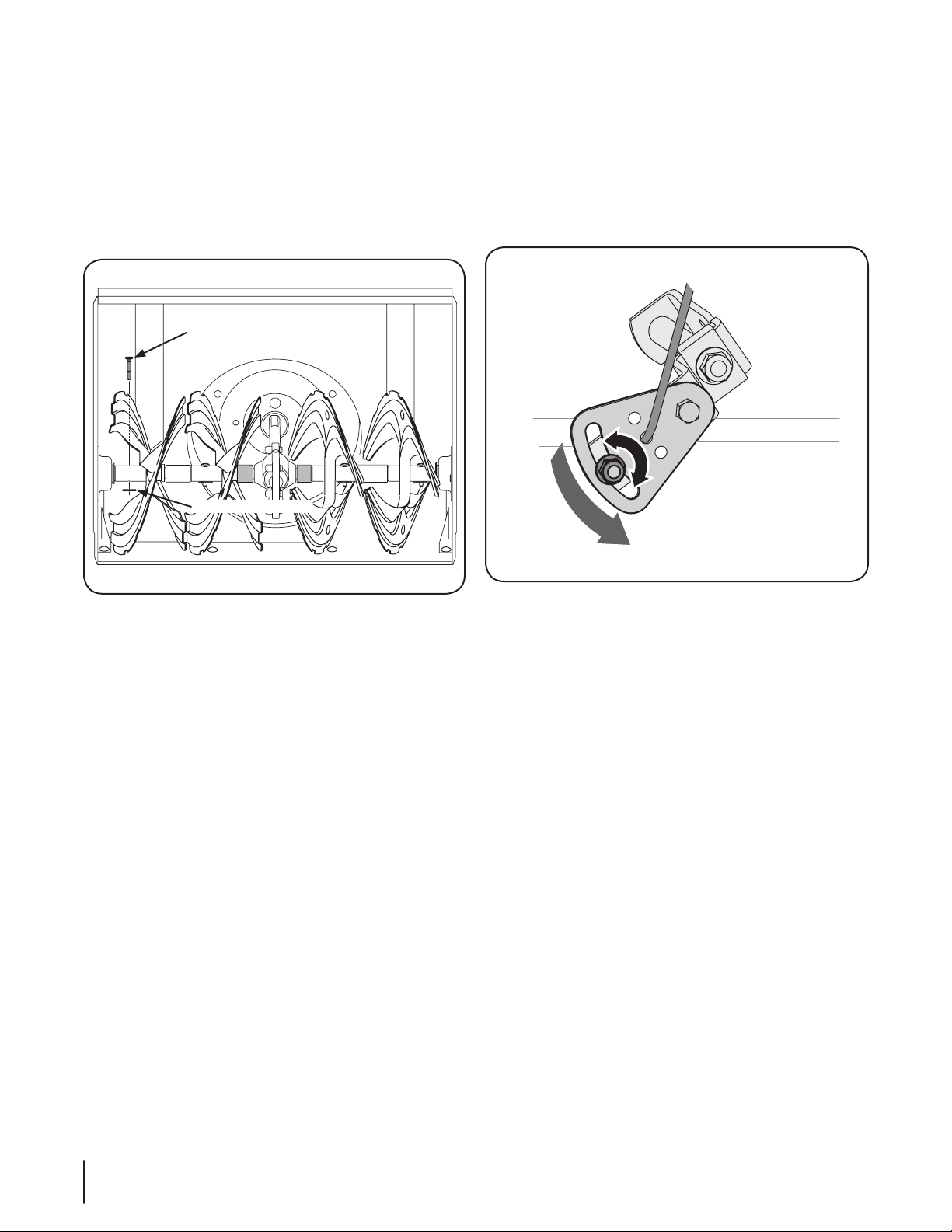
NOTE: When lubricating the hex shaft, be careful not to get
Shear Pin
Bow-Tie Cotter Pin
any oil on the aluminum drive plate or the rubber friction
wheel. Doing so will hinder the snow thrower’s drive
system. Wipe off any excess or spilled oil.
Auger Shaft
At least once a season, remove the shear pins from the auger
shaft. Spray lubricant inside the shaft and around the spacers and
the flange bearings found at either end of the shaft.
See Fig. 6-4.
Adjustments
Shift Cable
If the full range of speeds (forward and reverse) cannot be
achieved adjust the shift cable as follows:
Place the shift lever in the fastest forward speed position.1.
Loosen the hex nut on the shift cable index bracket. See 2.
Fig. 6-5.
Figure 6-4
Figure 6-5
Pivot the bracket downward to take up slack in the cable. 3.
Retighten the hex nut.4.
Auger Control
Refer to the Assembly and Set-up section for instructions on
adjusting the auger control cable.
Chute Assembly
Refer to the Assembly and Set-up section for instructions on
adjusting the chute assembly.
Skid Shoes
Refer to the Assembly and Set-up section for instructions on
adjusting the skid shoes.
18 se c t i O n 6— Ma i n t e n a n c e & ad j u s t M e n t s
Page 19
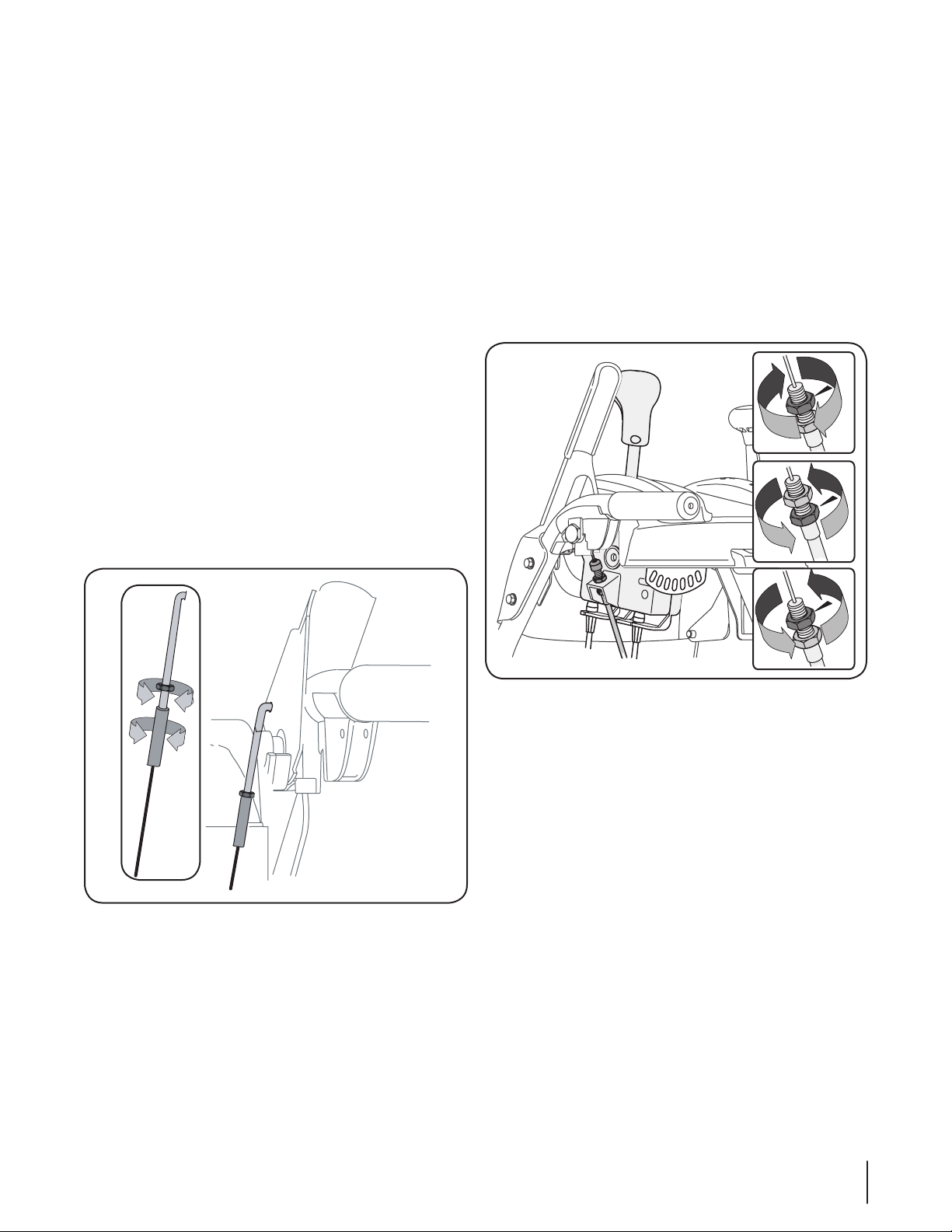
Drive Control
When the drive control is released and in the disengaged “up”
position, the cable should have very little slack. It should NOT be
tight.
NOTE: If excessive slack is present in the drive cable or if the snow
thrower’s drive is disengaging intermittently during operation,
the cable may be in need of adjustment.
Check the adjustment of the drive control as follows:
With the drive control released, push the snow thrower 1.
gently forward. The snow thrower should roll freely.
Engage the drive control and gently attempt to push the 2.
snow thrower forward. The track should not turn. The snow
thrower should not roll freely.
With the drive control released, move the shift lever back 3.
and forth between the R2 position and the F6 position
several times. There should be no resistance in the shift
lever.
If any of the above tests failed, the drive cable is in need of 4.
adjustment. Proceed as follows:
To readjust the drive, loosen the hex jam nut on the auger 5.
control cable “Z” fitting.
Thread the ferrule without turning the cable onto the “Z” 6.
fitting until there is no slack in the cable. See Fig. 6-6. Do
not overtighten the cable. Hold the flats on the ferrule with
pliers and tighten the jam nut against the ferrule.
Chute Directional Control
If the chute assembly does not have full range from left-to-right,
the chute control cables can be adjusted to take up slack:
NOTE: When making any adjustments to the chute directional
control cables be sure that the handle is in the center positon to
ensure proper adjustment.
Using a ½” wrench, loosen the upper and lower hex nuts 1.
found on one cable adjuster.
Grasp the metal cable housing and gently pull downward 2.
to take up slack (usually no more than 1⁄4-inch) in the cable
before retightening both hex nuts.
Repeat on the other cable adjuster until the chute 3.
assembly has full range from left-to-right. See Fig. 6-7.
Rotate the coupling end of the cable counterclockwise to 7.
provide more slack.
Retighten the hex jam nut. See Fig. 6-6.8.
Repeat Auger Control Test to verify proper adjustment has 9.
been achieved.
Figure 6-6
Figure 6-7
Off-Season Storage
If the snow thrower will not be used for 30 days or longer, follow
the storage instructions below.
Lubricate the machine as instructed earlier in this section.1.
Store in a clean, dry area.2.
If storing the snow thrower in an unventilated area, 3.
rustproof the machine using a light oil or silicone to coat
the snow thrower.
Clean the exterior of the engine and the snow thrower.4.
NOTE: Refer to the Engine Maintenance section for information
on storing your engine.
19se c t i O n 6 — Ma i n t e n a n c e & ad j u s t M e n t s
Page 20
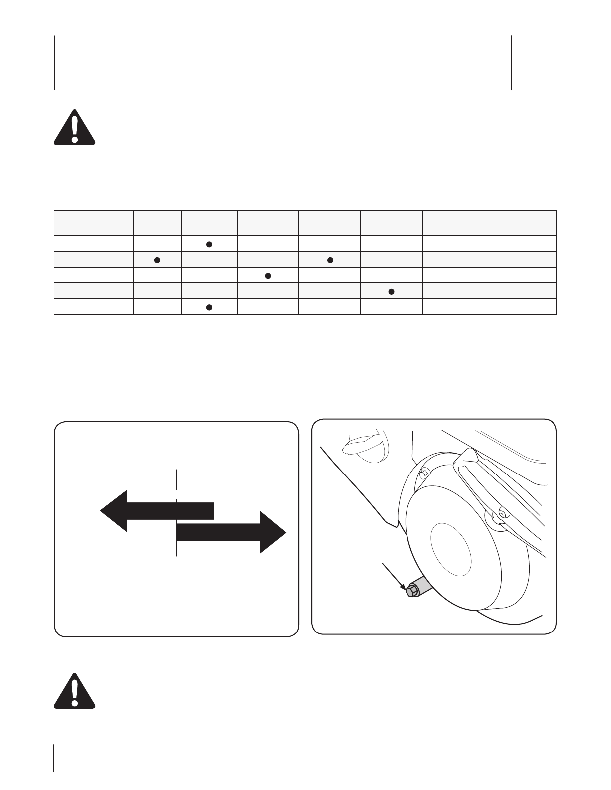
5W-30
0W-30
(°f)
(°C)
-40° -20° 0° 20° 40°
-30° -20° -10 ° 0°
0W-30
5W-30
Synthetic
Oil Plug
Engine Maintenance
7
WARNING! To prevent accidental start-up, shut off
the engine and remove the ignition key before
performing any type of engine maintenance.
Maintenance Schedule
TasksFirst 5 Hrs.Each Use or
Every 5 Hrs.
Check engine oil
Change engine oil
Check spark plug
Service spark plug
Clean exhaust area
Every Season
or 25 Hrs.
Oil Recommendations
When adding oil to the engine, refer to the viscosity chart
below (Fig. 7-1). Engine oil capacity is 600 ml (approx. 20
oz.). Do not over-fill. Use a 4-stroke, or an equivalent high
detergent, premium quality motor oil certified to meet or
exceed U.S. automobile manufacturer’s requirements for service
classification SG, SF. Motor oils classified SG, SF will show this
designation on the container.
Periodic inspection and adjustment of the engine is essential if
high level performance is to be maintained. Regular maintenance
will also ensure a long service life. The required service intervals
and the type of maintenance to be performed are described
in the table below. Follow the hourly or calendar intervals,
whichever occur first. More frequent service is required when
operating in adverse conditions.
Every Season
or 50 Hrs.
Every Season
or 100 Hrs.
Service Dates
Changing Engine Oil
NOTE: Check the oil level before each use and after every five
hours of operation to be sure the correct oil level is maintained.
Refer to Checking Oil Level in the Assembly & Set-Up Section.
Place a suitable oil collection container under the oil drain 1.
plug.
Remove the oil drain plug, Figure 7-2.2.
CAUTION: DO NOT use nondetergent oil or
2-stroke engine oil. It could shorten the engine’s
service life.
20
Figure 7-1
Figure 7-2
Tip the engine to drain oil into the container. Used oil must 3.
be disposed of at a proper collection center.
Reinstall the drain plug and tighten it securely. 4.
Refill with the recommended oil and check the oil level, 5.
refer to Assembly & Set-Up Section for instructions.
Page 21
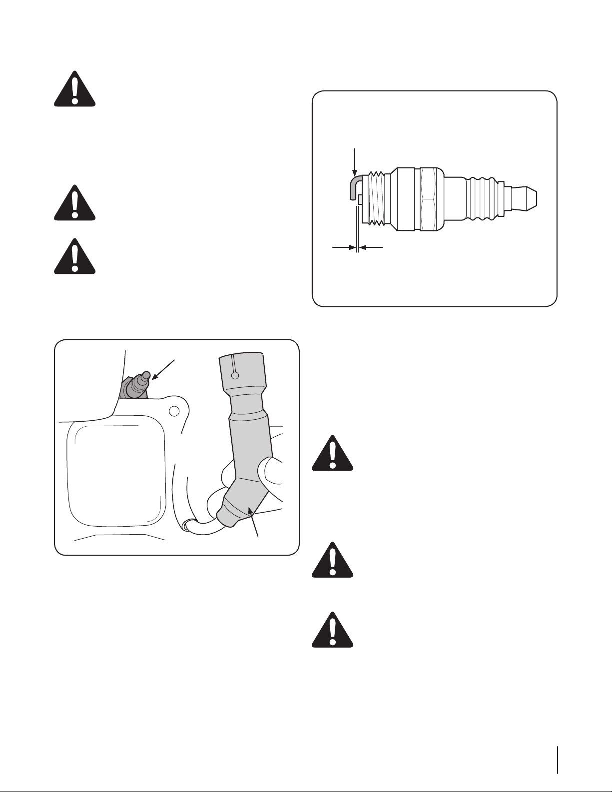
Reinstall the oil filler cap/dipstick securely.6.
Spark Plug
Spark Plug Boot
.02-.03 in.
(0.60-0.80 mm)
Electrode
CAUTION! Thoroughly wash your hands with soap
and water as soon as possible after handling
used oil.
NOTE: Please dispose of used motor oil in a manner that is
friendly to the environment. Take it to a recyling center or other
collection center.
Spark Plug
WARNING! DO NOT check for a spark with the
spark plug removed. DO NOT crank the engine with
the spark plug removed.
WARNING! If the engine has been running, the
muffler will be very hot. Be careful not to touch the
muffler.
To ensure proper engine operation, the spark plug must be
properly gapped and free of deposits.
Remove the spark plug boot and use a spark plug wrench 1.
to remove the plug, Fig. 7-3.
Measure the plug gap with a feeler gauge. Correct as 3.
necessary by bending the side electrode, Fig. 7-4. The gap
should be set to .02-.03 inches (0.60-0.80 mm).
Figure 7-4
Check that the spark plug washer is in good condition 4.
and thread the spark plug in by hand to prevent crossthreading.
After the spark plug is seated, tighten with a spark plug 5.
wrench to compress the washer.
NOTE: When installing a new spark plug, tighten ⁄-turn
after the spark plug seats to compress the washer. When
reinstalling a used spark plug, tighten ⁄- to ⁄-turn after
the spark plug seats to compress the washer.
Figure 7-3
Visually inspect the spark plug. Discard the spark plug if 2.
there is any apparent wear, or if the insulator is cracked or
chipped. Clean the spark plug with a wire brush if it is to be
reused.
CAUTION! The spark plug must be tightened
securely. A loose spark plug can become very hot
and can damage the engine.
Cleaning the Engine
If the engine has been running, allow it to cool for at least a half
an hour before cleaning. Periodically remove dirt build-up from
engine.
CAUTION! Do not spray the engine with water to
clean it because the water could contaminate the
fuel. Using a garden hose or pressure washing
equipment can also force water into the muffler
opening. Water that passes through the muffler can
enter the cylinder and cause damage.
WARNING! Accumulation of debris around the
muffler could cause a fire. Inspect and clean before
every use.
21se c t i O n 7 — en g i n e Ma i n t e n a n c e
Page 22

Off-Season Storage
Engines stored over 30 days need to be drained of fuel to
prevent deterioration and gum from forming in the fuel
system or on essential carburetor parts. If the gasoline in your
engine deteriorates during storage, you may need to have the
carburetor, and other fuel system components, serviced or
replaced.
Remove all fuel from the tank by running the engine until 1.
it stops.
NOTE: A fuel stabilizer (such as STA-BIL™ or ULTRA-FRESH™)
is an acceptable alternative in minimizing the formation
of fuel gum deposits during storage. Add stabilizer to
gasoline in fuel tank or storage container. Always follow
mix ratio found on stabilizer container. Run engine at least
10 minutes after adding stabilizer to allow it to reach the
carburetor.
Change the engine oil.2.
Remove the spark plug and pour one (1) ounce (30 ml) of 3.
clean engine oil through the spark plug hole and into the
cylinder. Cover spark plug hole with a rag and crank the
engine several times to distribute the oil. Replace spark
plug.
Clean debris from around the engine, and under, around, 4.
and behind the muffler. Apply a light film of oil on any
areas that are susceptible to rust.
Store in a clean, dry and well ventilated area away from any 5.
appliance that operates with a flame or pilot light, such as a
furnace, water heater or clothes dryer. Avoid any area with
a spark producing electric motor, or where power tools are
operated.
If possible, avoid storage areas with high humidity.6.
Keep the engine level in storage. Tilting the engine can 7.
cause fuel or oil leakage.
22 se c t i O n 7— en g i n e Ma i n t e n a n c e
Page 23
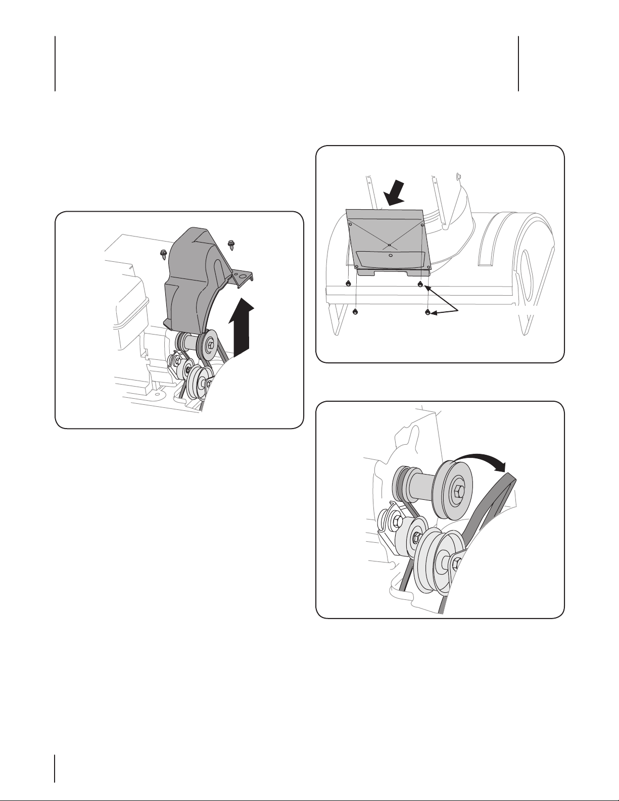
Self-Tapping Screws
Service
8
Belt Replacement
Auger Belt
NOTE: It is not necessary to remove both belts in order to change
either one. If changing just one belt, be certain to check the
condition of the other belt.
Remove the plastic belt cover at the front of the engine by 1.
removing the two self-tapping screws. See Fig. 7-1.
Remove the frame cover from the underside of the snow 4.
thrower by removing self-tapping screws which secure it.
See Fig. 7-2.
Figure 7-2
Roll the auger belt off the engine pulley. See Fig. 7-3.5.
Figure 7-1
Drain the gasoline from the snow thrower, or place a piece 2.
of plastic film under the gas cap.
Tip the snow thrower up and forward so that it rests on its 3.
auger housing.
Figure 7-3
23
Page 24
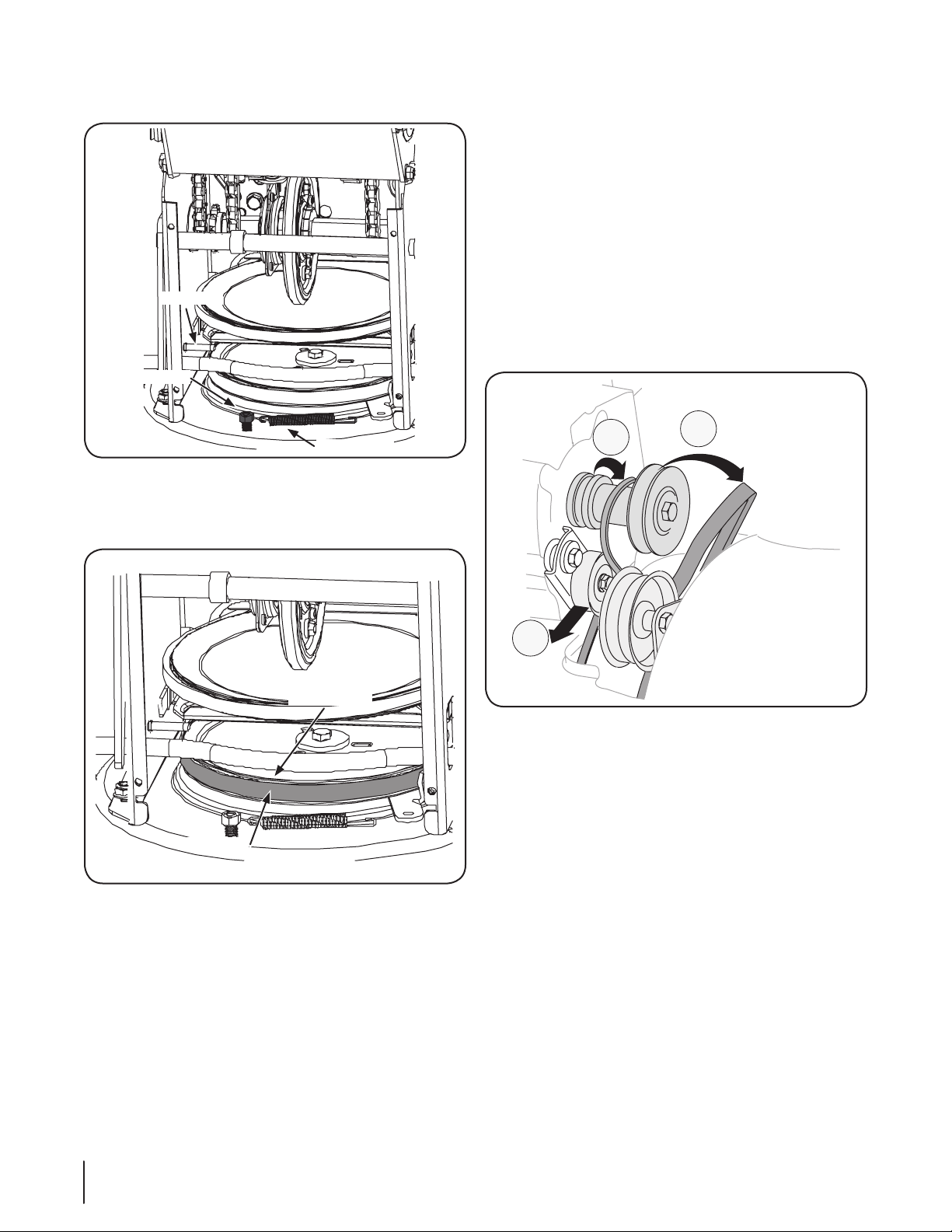
Unhook the idler spring from the hex bolt on the auger 6.
A
B
C
Auger Belt
Auger Pulley
Idler Spring
Hex Bolt
Stop Bolt
housing. See Fig. 7-4.
Figure 7-4
Lift the auger belt from the auger pulley, and slip belt 7.
between the support bracket and the auger pulley. Repeat
this step for the front auger belt. See Fig. 7-5.
Drive Belt
To remove and replace your snow thrower’s auger belt, proceed
as follows:
Remove the plastic belt cover on the front of the engine by 1.
removing the two self-tapping screws. Ref. Fig. 7-1.
Drain the gasoline from the snow thrower.2.
Carefully pivot the snow thrower up and forward so that it 3.
rests on the auger housing.
Remove the frame cover from the underside of the snow 4.
thrower by removing self-tapping screws which secure it.
Ref. Fig. 7-2.
To remove the belt from the pulleys procede as follows:5.
Use a wrench to pivot the idler pulley toward the a.
right. See Fig. 7-6.
Replace auger drive belt by following instructions in 8.
reverse order.
24 se c t i O n 8— se r v i c e
Figure 7-6
Roll the auger belt off the engine pulley.b.
Lift the drive belt off engine pulley.c.
Back out the stop bolt until the support bracket rests on 6.
the auger pulley. See Fig. 7-4.
Figure 7-5
Page 25
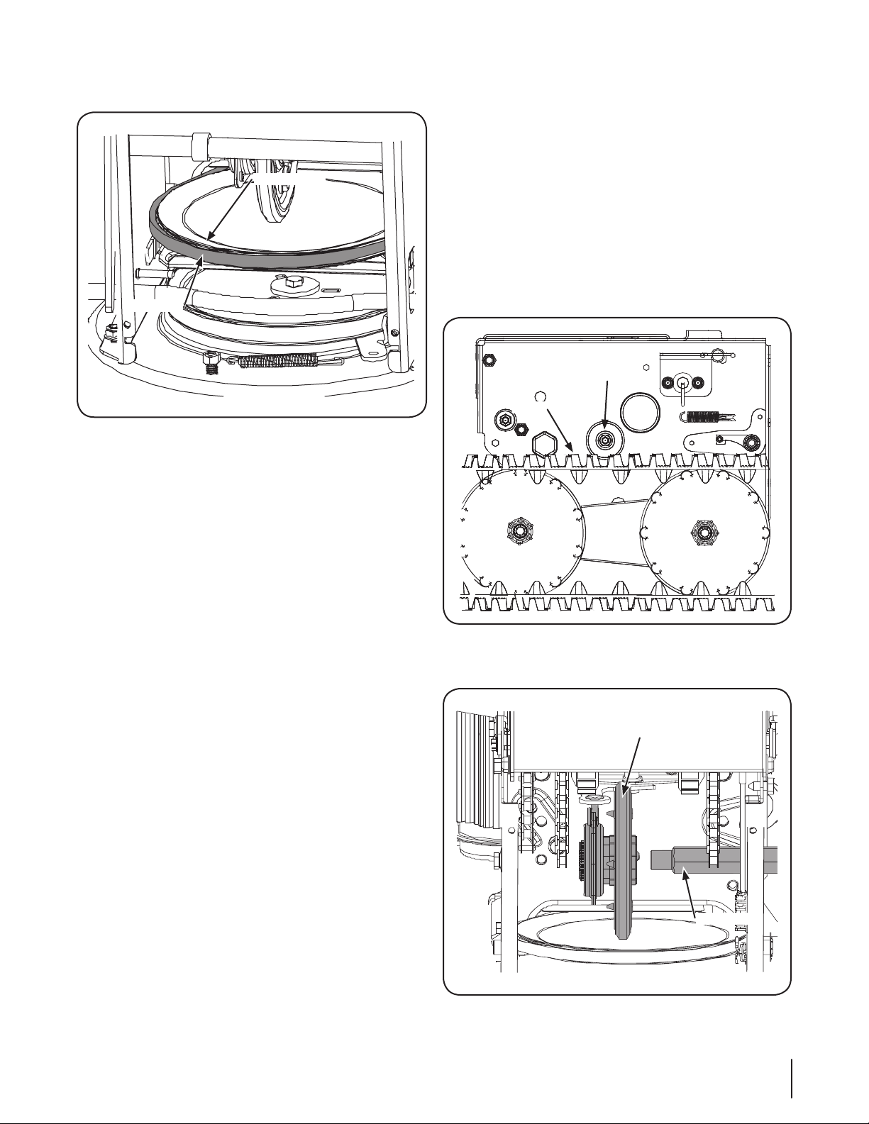
Slip the drive belt off the pulley and between friction 6.
Drive Pulley
Drive Belt
Hex Screw &
Bell Washer
Tra ck
Gear Shaft
Friction Wheel
Assembly
wheel and drive pulley. See Fig. 7-7.
Figure 7-7
Remove and replace belt in the reverse order.7.
NOTE: Engaging the drive control will ease re-assembly of
the belt.
Friction Wheel Removal
The rubber on the friction wheel is subject to wear and should be
checked after 25 hours of operation, and periodically thereafter.
Replace the friction wheel rubber if any signs of wear or cracking
are found.
Drain the gasoline from the snow thrower.1.
Tip the snow thrower up and forward, so that it rests on the 2.
housing.
Remove the self-tapping screws from the frame cover 3.
underneath the snow thrower.
Using a 4. ⁄” wrench to hold the gear shaft, remove the hex
bolt and bell washer on the left end of gear shaft. See Fig.
7-8 and 7-9.
Figure 7-8
Move the gear shaft to the right and slide the friction wheel 5.
assembly from the shaft. See Fig. 7-9.
Figure 7-9
25se c t i O n 8 — se r v i c e
Page 26
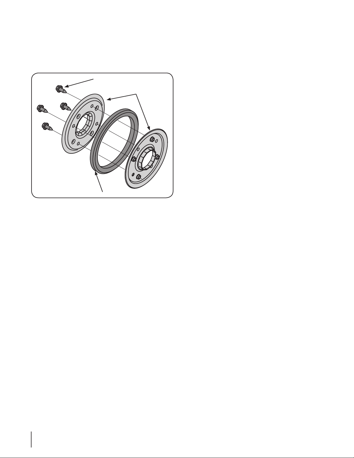
If repacing the entire assembly, put the new friction wheel 6.
Screws
Side Plates
Rubber Ring
assembly in place and follow the steps in reverse to reassemble. If you only want to replace the friction wheel
rubber continue with step 7.
Remove the four screws from the friction wheel assembly. 7.
See Fig. 7-11.
Figure 7-11
Remove the friction wheel rubber from between the 8.
friction wheel plates.
Reassemble new friction wheel rubber to the friction wheel 9.
plates and hub, tightening the four screws in rotation and
with equal force (between 6 ft.-lbs. and 9 ft.-lbs.).
Position the friction wheel assembly up onto the pin of 10.
the shift rod assembly, and slide the shaft through the
assembly. See Fig. 7-9. Reassemble in reverse order.
26 se c t i O n 8— se r v i c e
Page 27

Troubleshooting
Problem Cause Remedy
9
Engine fails to start Fuel tank empty, or stale fuel. 1.
Blocked fuel line.2.
Choke not in the ON position.3.
Faulty spark plug.4.
Safety key not in ignition switch on engine.5.
Spark plug wire disconnected.6.
Primer button not being used properly.7.
Engine runs erratic Engine running on CHOKE.1.
Blocked fuel line or stale fuel. 2.
Water or dirt in the fuel system.3.
Loss of power Spark plug wire loose.1.
Gas cap vent hole plugged.2.
Excessive vibration Loose parts or damaged auger.1. Stop the engine immediately and disconnect 1.
Snow Thrower fails to
propel itself
Snow Thrower fails to
discharge snow
Drive control cable in need of adjustment. 1.
Drive belt loose or damaged. 2.
Friction wheel worn.3.
Chute assembly clogged. 1.
Shear pin(s) sheared.2.
Foreign object lodged in auger. 3.
Auger control cable in need of adjustment. 4.
Auger belt loose or damaged.5.
Fill tank with clean, fresh gasoline. Fuel 1.
becomes stale after thirty days.
Clean the fuel line.2.
Move switch to the ON position3.
Clean, adjust gap or replace.4.
Insert the key fully into the switch.5.
Connect spark plug wire.6.
Refer to the Operation Section.7.
Move the choke lever to OFF position.1.
Clean the fuel line; fill the tank with clean, 2.
fresh gasoline.
Drain the fuel tank and carburetor. Refill with 3.
fresh fuel.
Connect and tighten spark plug wire.1.
Remove ice and snow from gas cap. Be 2.
certain vent hole is clear.
the spark plug wire. Tighten all bolts and
nuts. If vibration continues, have the snow
thrower serviced by an authorized service
dealer.
Adjust drive control cable. Refer to 1.
Maintenance & Adjustments Section.
Replace drive belt. Refer to the Service 2.
Section.
Replace the friction wheel.3.
Stop engine and disconnect spark plug wire. 1.
Clean chute and inside of auger housing with
clean-out tool or a stick.
Replace shear pin(s).2.
Stop engine immediately and disconnect 3.
spark plug wire. Remove object from auger.
Adjust auger control cable. Refer to the 4.
Maintenance & Adjustments Section.
Refer to Service Section.5.
27
Page 28
Replacement Parts
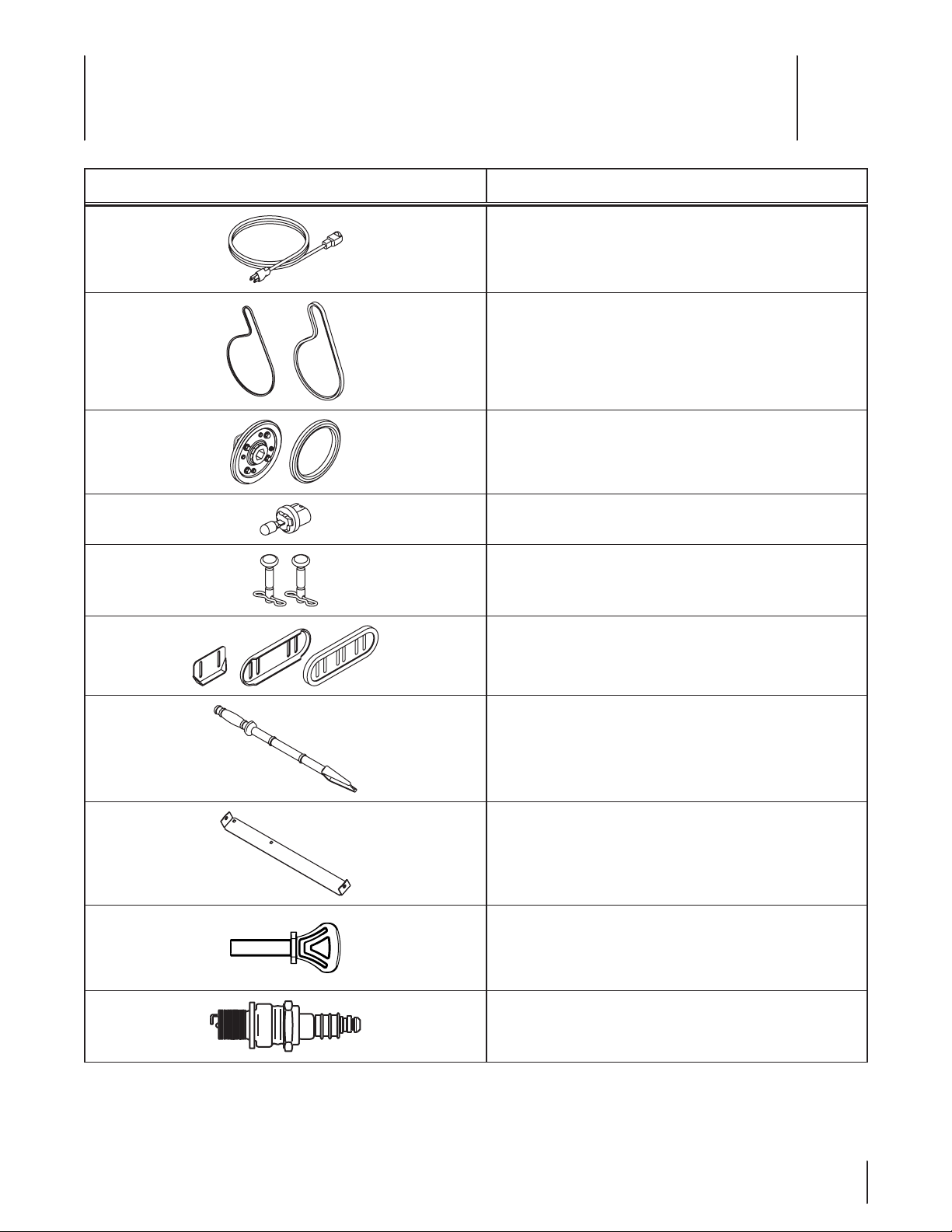
Component Part Number and Description
10
929-0071 Extension Cord, 110V
954-04050 Auger Drive Belt
954-0367 Wheel Drive Belt
684-04159 Friction Wheel Assembly
935-04054 Friction Wheel Rubber
725-1629 Lamp, 1141
738-04124A Shear Pin, 1.50
714-04040 Bow-tie Cotter Pin
784-5580 Skid Shoe, Standard
790-00091 Skid Shoe, Deluxe
731-05984A Skid Shoe, Polymer
731-2643 Chute Clean-out Tool
790-00121 Shave Plate, 26”
731-05632 Key
951-10292 Spark Plug
Phone (800) 800-7310 to order replacement parts or a complete Parts Manual (have your full model number and serial number ready).
Parts Manual downloads are also available free of charge at www.mtdproducts.com.
28
Page 29

Notes
11
29
Page 30

Troy-Bilt LLC (Troy-Bilt) and The United States Environment Protection Agency (U. S. EPA)
Emission Control System Warranty Statement
(Owner’s Defect Warranty Rights and Obligations)
The U. S. EPA and Troy-Bilt are pleased to explain the emissions control system warranty on your model year 2005 and later small off-road engine.
New small off-road engines must be designed, built and equipped to meet the stringent anti-smog standards. Troy-Bilt must warranty the emission
control system on your engine for the period of time listed below, provided there has been no abuse, neglect or improper maintenance of your small
off-road engine.
Your emission control system may include parts such as the carburetor, air cleaner, ignition system, exhaust system, and other associated emission-related components.
Where a warrantable condition exists, Troy-Bilt will repair your small off-road engine at no cost to your including diagnosis, parts and labor.
MANUFACTURER’S WARRANTY COVERAGE:
This emissions control system is warranted for two years. If any emission-related part on your engine is defective, the part will be repaired or
replaced by Troy-Bilt.
OWNER’S WARRANTY RESPONSIBILITIES:
As the small off-road engine owner, you are responsible for the performance of the required maintenance listed in your Owner’s Manual. Troy-Bilt
recommends that you retain all your receipts covering maintenances on your small off-road engine, but Troy-Bilt can not deny warranty solely for the
lack of receipts or for your failure to ensure the performance to all scheduled maintenance.
As the small off-road engine owner, you should however be aware that Troy-Bilt may deny your warranty coverage if your small off-road engine or
part has failed due to abuse, neglect, improper maintenance or unapproved modifications.
You are responsible for presenting your lawn mower to Troy-Bilt LLC’s distribution center or service center as soon as the problem exists. The warranty repairs should be completed in a reasonable amount of time, not to exceed 30 days. If you have a question regarding your warranty coverage,
you should contact your local Troy-Bilt dealer. To reach the Troy-Bilt Customer Dealer Referral Line, please call (866) 840-6483.
DEFECTS WARRANTY REqUIREMENTS FOR 1995 AND LATER SMALL OFF-ROAD ENGINES:
This section applies to 1995 and later small off-road engines. The warranty period begins on the date the engine or equipment is delivered to an
ultimate purchaser.
(a) General Emissions Warranty Coverage
Troy-Bilt must warrant to the ultimate purchaser and each subsequent purchaser that the engine is:
(1) Designed, built, and equipped so as to conform with all applicable regulations adopted by the Air Resources Board pursuant to its authority in
Chapters 1 and 2,Part 5, Division 26 of the Health and Safety Code; and
(2) Free from defects in materials and workmanship that cause the failure of a warranted part to be identical in all material respects to the part as
described in the engine manufacturer’s application for certification for a period of two years.
(b) The warranty on emissions-related parts will be interpreted as follows:
(1) Any warranted part that is not scheduled for replacement as required maintenance in the written instructions required by Subsection (c)
must be warranted for the warranty period defined in Subsection (a)(2). If any such part fails during the period of warranty coverage, it must be
repaired or replaced by Troy-Bilt according to Subsection (4) below. Any such part repaired or replaced under the warranty must be warranted
for the remaining warranty period.
(2) Any warranted part that is scheduled only for regular inspection in the written instructions required by Subsection (c) must be warranted for
the warranty period defined in Subsection (a)(2). A statement in such written instructions to the effect of “repair or replace as necessary” will
not reduce the period of warranty coverage. Any such part repaired or replaced under warranty must be warranted for the remaining warranty
period.
(3) Any warranted part that which is scheduled for replacement as required maintenance in the written instructions required by Subsection (c)
must be warranted for the period of time prior to the first scheduled replacement point for that part. If the part fails prior to the first scheduled
replacement, the part must be repaired or replaced by Troy-Bilt according to Subsection (4) below. Any such part repaired or replaced under
warranty must be warranted for the remainder of the period prior to the first scheduled replacement point for the part.
(4) Repair or replacement of any warranted part under the warranty provisions of this article must be performed at no charge to the owner at a
warranty station.
(5) Notwithstanding the provisions of Subsection (4) above, warranty services or repairs must be provided at all Troy-Bilt distribution centers that
are franchised to service the subject engines.
(6) The owner must not be charged for diagnostic labor that leads to the determination that a warranted part is in fact defective, provided that
such diagnostic work is performed at a warranty station.
Page 31

(7) The engine manufacturer is liable for damages to other engine components proximately caused by a failure under warranty of any warranted
part.
(8) Throughout the engine’s warranty period defined in Subsection (a)(2), Troy-Bilt will maintain a supply of warranted parts sufficient to meet
the expected demand for such parts.
(9) Any replacement part may be used in the performance of any warranty maintenance or repairs and must be provided without charge to the
owner. Such use will not reduce the warranty obligations of Troy-Bilt.
(10) Add-on or modified parts that are not exempted by the Air Resources Board may not be used. The use of any non-exempted add-on or
modified parts shall be grounds for disallowing a warranty claim made in accordance with this article. The engine manufacturer shall not be
liable under this article to warrant failures of warranted parts caused by the use of non-exempted add-on or modified part.
(c) Troy-Bilt will include a copy of the following emission warranty parts list with each new engine, using those portions of the list applicable to
the engine.
(1) Fuel Metering System
•Coldstartenrichmentsystem(softchoke)
•Carburetorandinternalparts
•FuelPump
(2) Air Induction System
•Aircleaner
•Intakemanifold
(3) Ignition System
•Sparkplug(s)
•MagnetoIgnitionSystem
(4) Exhaust System
(5) Miscellaneous Items Used in Above System
•Vacuum,temperature,position,timesensitivevalvesandswitches
•Connectorsandassemblies
GDOC-100171 Rev. A
Page 32

MANUFACTURER’S LIMITED WARRANTY FOR
The limited warranty set forth below is given by Troy-Bilt LLC with
respect to new merchandise purchased and used in the United States
and/or its territories and possessions, and by MTD Products Limited
with respect to new merchandise purchased and used in Canada
and/or its territories and possessions (either entity respectively,
“Tro y-Bilt”).
“Troy-Bilt” warrants this product (excluding its Normal Wear Parts
and Attachme nts as described below) against defects in material and
workmanship for a period of two (2) years commencing on the date
of original purchase and will, at its option, repair or replace, free of
charge, any part found to be defective in materials or workmanship.
This limited warranty shall only apply if this product has been
operated and maintained in accordance with the Operator’s Manual
furnished with the product, and has not been subject to misuse,
abuse, commercial use, neglect, accident, improper maintenance,
alteration, vandalism, theft, fire, water, or damage because of other
peril or natural disaster. Damage resulting from the installation or
use of any part, accessory or attachment not approved by Troy-Bilt
for use with the product(s) covered by this manual will void your
warranty as to any resulting damage.
Normal Wear Parts are warranted to be free from defects in material
and workmanship for a period of thirty (30) days from the date of
purchase. Normal wear parts include, but are not limited to items
such as: batteries, belts, blades, blade adapters, tines, grass bags,
wheels, rider deck wheels, seats, snow thrower skid shoes, friction
wheels, shave plates, auger spiral rubber and tires.
Attachments — Troy-Bilt warrants attachments for this product
against defects in material and workmanship for a period of one (1)
year, commencing on the date of the attachment’s original purchase
or lease. Attachments include, but are not limited to items such as:
grass collectors and mulch kits.
HOW TO OBTAIN SERVICE: Warranty service is available, WITH
PROOF OF PURCHASE, through your local authorized service dealer.
To locate the dealer in your area:
In the U.S. A.
Check your Yellow Pages, or contact Troy-Bilt LLC at P.O. Box 361131,
Cleveland, Ohio 44136-0019, or call 1-866-840-6483,
1-330-558-7220 or log on to our Web site at www.troybilt.com.
In Canada
Contact MTD Products Limited, Kitchener, ON N2G 4J1, or call 1-800668-1238 or log on to our Web site at www.mtdcanada.com.
This limited warranty does not provide coverage in the following
cases:
a. Log splitter pumps, valves, and cylinders have a separate one-
year warranty.
b. Routine maintenance items such as lubricants, filters, blade
sharpening, tune-ups, brake adjustments, clutch adjustments,
deck adjustments, and normal deterioration of the exterior finish
due to use or exposure.
c. Service completed by someone other than an authorized service
deal er.
d. Troy-Bilt does not extend any warranty for products sold or
exported outside of the United States and/or Canada, and their
respective possessions and territories, except those sold through
Troy-Bilt’s authorized channels of export distribution.
e. Replacement parts that are not genuine Troy-Bilt parts.
f. Transportation charges and service calls.
g. Troy-Bilt does not warrant this product for commercial use.
No implied warranty, including any implied warranty of
merchantability of fitness for a particular purpose, applies after
the applicable period of express written warrant y above as to the
parts as identified. No other express warranty, whether written or
oral, except as mentioned above, given by any person or entity,
including a dealer or retailer, with respect to any product, shall
bind Troy-Bilt. During the period of the warranty, the exclusive
remedy is repair or replacement of the product as set for th above.
The provisions as set forth in this warranty provide the sole and
exclusive remedy arising from the sale. Troy-Bilt shall not be liable
for incidental or consequential loss or damage including, without
limitation, expenses incurred for substitute or replacement lawn
care services or for rental expenses to temporarily replace a
warranted product.
Some states do not allow the exclusion or limitation of incidental
or consequential damages, or limitations on how long an implied
warranty lasts, so the above exclusions or limitations may not apply
to you.
In no event shall recovery of any kind be greater than the amount of
the purchase price of the product sold. Alteration of safety features of
the product shall void this warranty. You assume the risk and liability
for loss, damage, or injury to you and your property and/or to others
and their property arising out of the misuse or inability to use the
product.
This limited warranty shall not extend to anyone other than the
original purchaser or to the person for whom it was purchased as a
gift.
HOW STATE LAW RELATES TO THIS WARRANT Y: This limited
warranty gives you specific legal rights, and you may also have other
rights which vary from state to state.
IMPORTANT: Owner must present Original Proof of Purchase to
obtain warranty coverage.
Troy-Bilt LLC, P.O. BOX 361131 CLEVELAND, OHIO 44136-0019; Phone: 1-866-840-6483, 1-330-558-7220
MTD Canada Limited - KITCHENER, ON N2G 4J1; Phone 1-800-668-1238
GDOC-100166 REV. A
 Loading...