

Page 1

i.'V', jVv,'
OWNER/OPERATOR MANUA
:insfi)^iE3[№i'5 ,'
- -' ,-','•*/,f;*'.' _'!■ •' ;..■«■ /i“,- ''’^.%-V>r^--iii -'!i^.-‘-':«-."r'*.'v_-"j,:-' ■■*'
«m«p M ;■ ■ve^-'-f--;i^v---
uir::i-i ii7I-ie:i:i
Assembly, Safety, Operating and Maintenance Instructtons.
PLEASE READ CAREFULLY!
Page 2

TABLE OF CONTENTS
Page
INTRODUCTION 1
FOR SERVICE OR PARTS 1
MOWER IDENTIFICATION NUMBERS 1
SECTION 1: RULES FOR
SAFE OPERATION
Training................................................................................. 2
Preparation
Operation.............................................................................. 3
Maintenance and Storage
Safety Decals....................................................................... 4
SECTION 2: ASSEMBLY INSTRUCTIONS
Check For Shipping Damage
Toois Needed For Assembiy
Mower Assembly Steps .................................................... 5
Electric Start Assembly Steps
SECTION 3: MOWER AND
ENGINE CONTROLS
Blade Drive Controls......................................................... 15
Wheel Drive Controls
Handlebar Height Adjustment ........................................ 16
Height of Cut Adjustment................................................. 16
Engine Throttie Control
Fuel Shut-Off Valve............................................................ 17
Engine Recoii Starter
Key Switch Starter ............................................................ 17
SECTION 4: OPERATING INSTRUCTIONS
Preparation Before Starting............................................. 18
To Start the Engine............................................................ 19
To Engage the Blade
To Engage the Wheels
To Stop the Engine............................................................ 20
Operating the Mower......................................................... 20
..........................................................................
................................................
...........................................
............................................
.......................................
........................................................
...................................................
........................................................
........................................................
......................................................
2
4
5
5
10
16
16
17
19
20
SECTION 5: MAINTENANCE AND
ADJUSTMENTS
Maintenance Chart
Adjusting Wheei Drive Traction
Height of Cut Adjustment
Handlebar Height Adjustment ....................................
Sharpening or Repiacing the Mower Biade ..
Clean the Mower Housing and Discharge
Chute............................................................................
Check Tire Pressure......................................................
Check Bolts, Screws and Nuts....................................
Lubrication......................................................................
Wheel Drive Belt Tension.............................................
Repiacing the Wheel Drive Belt
Blade Drive Belt Tension
Replacing the Blade Drive Belt ..................................
Wheel Drive Chain Tension
Replacing the Blade Brake Band
Battery Care In Service ................................................
Battery Storage
Battery Removal and Replacement
Starting the Electric Start
Engine With the Recoil Starter
Engine Crankcase Oil
Engine Air Cleaner
Carburetor Adjustments...............................................
Air Cooling Service........................................................
Spark Plug.......................................................................
Throttle Cable Adjustments ........................................
Off-Season Storage
Engine Identification Numbers
Blade Brake Control Test Procedure
SECTION 6: TROUBLESHOOTING
Swivel Wheel Kit
........................................................
..................................
............................................
..................................
............................................
........................................
...............................
..............................................................
...........................
...............................
...................................................
........................................................
.......................................................
...................................
.......................
......................
............................................................
MAINTENANCE RECORD . Inside Back
Page
21
22
23
23
24
25
25
25
25
25
26
27
28
29
29
30
31
31
32
32
33
33
33
33
33
33
33
34
35
36
Cover
MODEL IDENTIFICATION
22" Push Model. 5HP
Recoil Start Engine.
NOTE: Optional swivel wheels are available for your TUFF-CUT® Mower. Please refer to Page 36 for additional details.
22"Self-Propelled Model.
5HP Recoil Start or
optional Electric Start Engine.
24" Self-Propelled Model.
8HP Recoil Start or
optional Electric Start Engine.
P
Page 3

INTRODUCTION
Dear Owner:
Vi/e at Garden Wa/ want to thank you for purchasing our TROY-BILT TUFF-CUT® High
Wheei Mower.
Your new mower is a professionai-quaiity, rugged machine that wiii handie most ter
rain and perform dependabiy for many iong hours of heavy use. The big rear wheeis
roii smoothly through tall grass, and over uneven ground and rough areas with ease. Its
perfect balance makes it much more responsive and maneuverable than conventional
mowers. And its wide mowing path, extra horsepower, and easy trimming abilities
mean you’ll get your mowing chores done in as little time as possible.
We have prepared this Manual to assist you in the safe operation and care of your
new TUFF-CUT High Wheel Mower. BEFORE YOU OPERATE THE MOWER PLEASE
READ THIS WHOLE MANUAL CAREFULLY! Most importantly, please follow all of the
safety instructions given in Section 1, “Rules for Safe Operation.’’ Failure to do so could
result in serious injury or damage to equipment or property.
It is our sincere hope that you enjoy using your mower. It is designed and con
structed to give you superior results and dependable service. Of course, if you have
any questions or problems in operating or servicing your mower, please remember that
we are here to serve you. We want to do everything we can to make sure that you are
completely satisfied 100 percent of the time.
Thank you.
Dean Leith, Jr.
Sales Manager
FOR SERVICE OR PARTS
For service or operating questions, or replacement
parts, you can either contact the factory or see your
local servicing dealer. Our addresses and telephone
numbers are listed below for your convenience.
Our telephone numbers are:
In the U.S.A.:
For Technical Service call Toll-Free: 1-800-833-6990
For Parts Service call Toll-Free: 1-800-648-6776
In Canada:
Call Toll-Free: 1-800-225-3585
Send correspondence to:
In the U.S.A.:
Troy-Bilt Mfg. Company
102nd St. & 9th Ave.,
Troy, New York 12180
In Canada:
Garden Way Canada, Inc.,
1515 Matheson Blvd., EUnitBII
Mississauga, Ontario L4W 2P5
For engine service, contact an Authorized Briggs &
Stratton Service Dealer. Look in the Yellow Pages of
your telephone directory, under "Engines-Gasoline."
Your Service Dealer can handle all parts, repairs, and
warranty service for problems concerning the engine
alone. For full details on the engine manufacturer's
limited warranty, please see the separate engine
owner's pamphlet that was included with this Manual.
(If you have any difficulty in locating an authorized
dealer or in obtaining warranty service, please contact
our Technical Service Department for assistance.)
RECORD YOUR MODEL
AND SERIAL NUMBERS
The arrow in the photo below shows the location of
the Model and Serial Number decal on your mower.
We will need these numbers if you call or write us for
parts or service assistance. For ready reference,
please record these numbers in the spaces provided
below.
MODEL NUMBER:.
SERIAL NUMBER:
DATE OF DELIVERY:
Page 4
SECTION 1
A Rules for Safe Operation
Safe Operation is So Important...
Read the following rules carefully, and pay particular
attention to safety instructions printed elsewhere in this
manual. Failure to comply with safety instructions could
endanger your personal safety and the equipment and
property of yourself and others.
SAFETY ALERT SYMBOL
This symbol is used to alert you to important safety
messages in this manuai. When you see this
A
symbol, carefully read the message that follows.
The TUFF-CUT® Mower conforms to the CPSC
(Consumer Product Safety Commission) safety
standard 16 CFR Part 1205 for walk-behind pow
er lawn mowers. The CPSC is an agency of the
Federal Government, established and empowered
by Congress in 1972, to make and enforce safety
standards for consumer products sold in the Unit
ed States. All rotary walk-behind power lawn mow
ers manufactured after June 30, 1982 are
required to meet CPSC federally-mandated stan
dards. Accordingly, the TUFF-CUT® Mower meets
the standards in effect at the time of manufacture.
The TUFF-CUT® Mower also meets voluntary
safety standard B-71.1-1986, which is sponsored
by the Outdoor Power Equipment Institute and is
published by the American National Standards
Institute.
TRAINING:
1. Read both this Owner/Operator Manuai and the sep
arate engine owner’s pamphlet completely before using
the mower. Be thoroughly familiar with the controls and
proper use of the mower. Know how to stop the mower
and disengage the controls quickly in an emergency.
2. Never allow children to operate the mower. Do not
allow adults to operate the mower without proper
instruction.
3. Keep the area of operation clear of all persons, par
ticularly small children, and pets.
4. Under California law, and under the laws of several
other states, you are not permitted to operate an inter
nal combustion engine using hydrocarbon fuels on any
forest-covered, brush-covered, or grass-covered land, or
on land covered with grain, hay, or other flammable
agricultural crop, without an engine spark arrester in
continuous effective working order.
The engine on your power equipment, like most out
door power equipment, is an internal combustion engine
that burns gasoline, a hydrocarbon fuel. Therefore, your
power equipment must be equipped with a spark arrester
muffler in continuous effective working order. The spark
arrester must be attached to the engine exhaust system
in such a manner that flames or heat from the system will
not ignite flammable material. Failure of the owner/operator of the equipment to comply with this regulation is a
misdemeanor under California law, and may also be a
violation of other state and/or federal regulations, laws,
ordinances, or codes. Contact your local fire marshall or
forest service for specific information about what regula
tions apply in your area.
PREPARATION:
1. Thoroughly inspect the area where the mower is
to be used and remove all stones, sticks, wires,
bones, nails and other foreign objects.
2. Do not operate the mower when barefoot or
wearing open sandals. Always wear substantial
footwear. The operation of any powered machine can
result in foreign objects being thrown by high speed
rotating parts. Always wear approved safety glasses
or other eye protection when using the mower.
3. Do not wear loose-fitting clothing that could get
caught in moving parts.
4. Mow only in daylight, or in good artificial light.
5. Disengage the blade drive mechanism, and the
self-propelled mechanism on units so equipped,
before starting the engine.
6. Never operate the mower in wet grass. Always be
sure of your footing; keep a firm hold on the
handlebar and walk; never run.
Disengage Blade
and Wheel Drive
Controls Before
Starting
Page 5
7. Never attempt to make a wheel height adjustment
while the engine is running.
8. Never operate the mower without the grass dis
charge deflector and all guards in place.
9. Never attempt to disconnect any safety devices or
to defeat the purpose of these safety devices.
10. Gasoline is highly flammable and its vapors are
explosive. Handle with extreme care. Use an approved
fuel container.
11. Check the fuel before starting the engine. Do not
fill the gasoline tank indoors, when the engine is run
ning or until the engine has been allowed to cool for
several minutes after running. Replace the fuel cap
securely and clean off any spilled gasoline before start
ing the engine.
12. Keep smoking materials, sparks and flame away
from the fuel tank or fuel container.
13. Move machine away from gasoline fumes before
starting engine.
14. Poison/Danger — Causes Severe Burns. The bat
tery on electric start models contains sulfuric acid. Avoid
contact with skin, eyes or clothing. Antidote: EXTER
NAL - Flush immediately with lots of water. INTERNAL
- Drink large quantities of water or milk. Follow with
milk of magnesia, beaten egg or vegetable oil. Call
physician immediately. Eyes - Flush with water for 15
minutes and get prompt medical attention. Keep out of
reach of children.
15. Batteries produce explosive gases. Keep sparks,
flame, or cigarettes away. Ventilate when charging or
using in an enclosed space. Always shield eyes when
working near batteries.
16. At the start of each season and every 10 operating
hours, perform the Blade Brake Control Test Procedure
described on Page 34.
OPERATION:
1. Do not put hands or feet near or under any rotating
parts. Keep clear of the mower blade and discharge
opening at all times.
2. Do not change the engine governor settings or over
speed the engine.
Stop The Blade
Before Crossing
Gravel Areas
5. Stop the engine, disconnect the spark plug wire,
and wait for all moving parts to stop before inspecting,
cleaning, adjusting or repairing the mower.
6. Never leave the mower unattended with the engine
running. Disconnect the spark plug wire and keep the
wire away from the spark plug to prevent accidental
starting. Remove the key on electric start models to
prevent unauthorized use.
7. Shut off the engine, disconnect the spark plug wire
and keep the wire away from the spark plug to prevent
accidental starting. Make sure that rotating parts have
completely stopped before cleaning out the discharge
opening.
Disconnect Spark Plug
Wire To Avoid
Accidental Starts
8. If the mower should start to vibrate abnormally, stop
the engine, disconnect the spark plug wire, and wait
for all moving parts to stop. Then, check immediately
for the cause. Vibration is generally a warning of
trouble.
9. After striking a foreign object, stop the engine and
disconnect the spark plug wire. Keep the spark plug
wire away from the plug to prevent accidental starting.
Wait for all moving parts to completely stop and then
inspect the mower for damage. Repair the damage
before restarting and operating the mower.
10. Do not run the engine indoors. Exhaust gases
contain carbon monoxide, a deadly gas that is odor
less and colorless. Always run the engine outdoors
and make sure there is adequate ventilation.
11. The Outdoor Power Equipment Institute recom
mends that you mow across the face of slopes; never
up and down. Exercise extreme caution when chang
ing direction on slopes. Do not mow excessively steep
slopes.
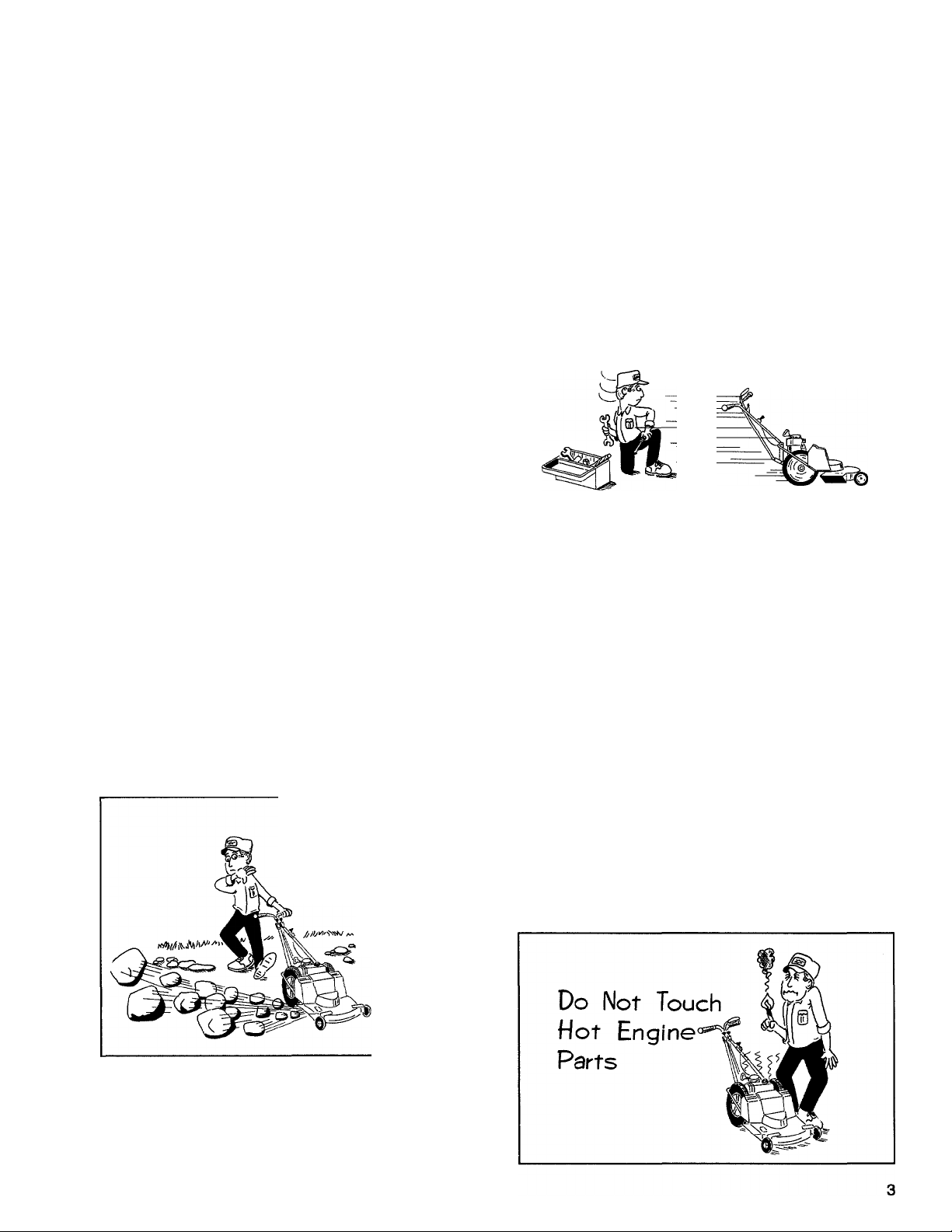
12. Do not touch engine parts which may be hot from
operation. Allow parts to cool before inspecting, clean
ing or repairing.
3. Stop the blade when crossing gravel drives, walks,
or roads where thrown objects would be a hazard.
4. Stop the blade when you are approached by any
child, pet, or inattentive person. (Curious toddlers can
too quickly endanger themselves.)
Page 6

MAINTENANCE AND
STORAGE:
1. Check the blade and the engine mounting bolts at
frequent intervals for proper tightness.
2. Keep all nuts, bolts, and screws tight to be sure the
equipment is in safe working condition.
3. Never store the mower with gasoline in the tank in
side a building where fumes may reach an open flame
or spark.
4. Allow the engine to cool before storing in any
enclosure.
^SAFETY DECALS
Safety decals are located near any area of potential
danger. Please contact us for replacement decals if
5. To reduce fire hazard, keep the engine free of
grass, leaves, or excessive grease.
6. Store gasoline in a cool, well-ventilated area, safely
away from any spark or flame-producing equipment.
Store in an approved container, safely out of the reach
of children.
7. Stop the engine, disconnect the spark plug wire,
and wait for ail moving parts to stop before inspecting,
cleaning, adjusting or repairing the mower. If the engine
has been running, allow the hot muffler to cool before
working near it.
they are missing, illegible, or damaged. See your Parts
Catalog for Part Number identification.
GRASP HANDLE GRIP WHEN
PULLING RECOIL STARTER.
1240263 (10/87)
ROTATING BLADE OR THROWN 0BJE(H^ CAN RESULT IN SERIOUS INJURY.
DO NOT OPERATE MOWER WITHOUT GRASS
DISCHARGE DEFLECTOR OR GUARD IN PLACE.
DO NOT PUT HANDS OR FEET NEAR OR UNDER
ROTATING PARTS. KEEP CLEAR OF THE DIS
CHARGE OPENING AT ALL TIMES.
Awarning
FAILURE TO FOLLOW SAFE OPERATING PROCEDURES MAY RESULT IN
INJURY. TO HELP REDUCE RISK:
1. READ OWNER/OPERATOR MANUAL.
2. KEEP ALL SAFETY GUARDS AND SHIELDS IN PLACE.
3. KEEP AREA OF OPERATION CLEAR OF ALL PERSONS AND PETS.
4. STOP ENGINE, DISCONNECT SPARK PLUG WIRE, AND WAIT FOR
ALL MOVEMENT TO STOP BEFORE CLEANING, INSPECTING OR
REPAIRING MACHINE.
For replacemenl Manual write lo: GARDEN WAY MFG. CO., TROY, N.Y. 1Z180 eooTBO/a?) J
ADANGER
80073 (9/87)
ACAUTION
DO NOT START ENGINE OR RUN MOWER UNLESS
BELT/PULLEY SAFETY COVER IS SECURELY FAS
TENED IN PLACE.
FAILURE TO INSTALL COVER CAN RESULT IN
INJURY FROM MOVING PARTS SUCH AS BELTS,
PULLEYS, CHAINS, ETC. T240226<9/87,
Page 7
SECTION 2
Assembly Instructions
Your TUFF-CUT® Mower is shipped partially unassembled for safe shipment to you. You’ll find all the
loose parts and necessary hardware packed inside the shipping carton. Please follow the simple steps in
this Section for quick, easy and complete mower and engine preparation. After your mower is assembled,
carefully read and follow all of the safety and operating instructions in this manual and in the separate
engine owner’s pamphlet.
IMPORTANT
The engine on your mower was shipped without oil in
the crankcase. See Step 6 for oil filling instructions.
CHECK FOR SHIPPING DAMAGE
If you notice any freight damage or missing parts
either at the time of delivery or later during assembly,
make sure that you put it in writing, within 15 days, that
you intend to file a claim. Tell the driver, or phone the
truck terminal, that you intend to file a written claim.
They will advise you on how to proceed. However, if you
have any problems with this procedure, please call us
so that we can help you to get satisfaction.
Also, be sure to notify us if you find any parts are miss
ing or damaged. We will arrange to replace damaged
or missing parts as quickly as possible.
TOOLS NEEDED FOR ASSEMBLY
All Models:
• Two each of 7/16", 9/16", or Adjustable-Style
Wrenches
• Small Adjustable Pliers
• Phillips Head Screwdriver
• Oil Funnel
• Tire Pressure Gauge (pocket-type)
Electric Start Models:
• 1/2" or Adjustable-Style Wrench
E. Remove any protective wrapping from the upper and
lower ends of the handlebars. Also, there may be a plas
tic protective cap on the outer ends of the two rear wheel
mounting studs. If so, remove and discard the caps.
F. For shipping purposes only, a cardboard sleeve was
placed underneath the mower deck. Using care to avoid
cutting yourself on the sharpened blade (wear thick
gloves for extra protection), raise the front of the mower
and remove the cardboard sleeve.
HARDWARE PACKAGE
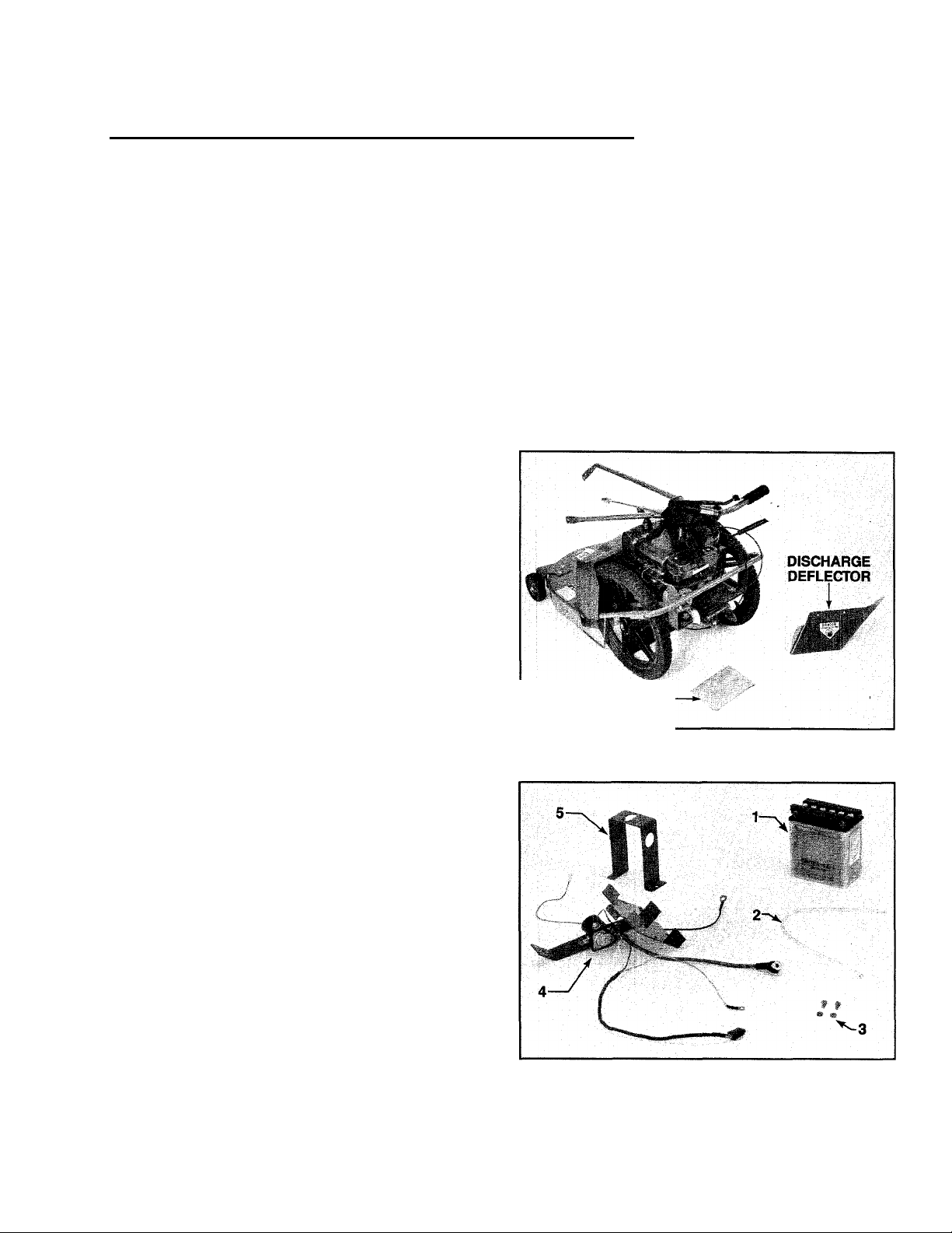
Photo 2-1: Remove mower, discharge deflector and
hardware package.
MOWER ASSEMBLY STEPS:
NOTE: All references to “Left” and “Right” are given
from the operator's position behind the handlebars.
STEP 1: Unpacking and Loose Parts
A. Remove the mower, discharge deflector, and hard
ware package from the shipping carton (lift carton off
base to remove mower). See Photo 2-1.
B. If you ordered an electric start model, also remove
the battery carton (containing battery, vent tube, and bat
tery bolts and nuts), the battery mounting bracket
assembly, and the battery hold-down clamp. See Photo
2-2.
C. The contents of the hardware bag can be identified
by referring to the separate “Hardware Bag Contents”
sheet that is included in your literature package.
D. Assembly should be done on a clean, level surface.
If you need to move the mower, be careful not to severely
bend or stretch any wires or cables.
Photo 2-2: Loose parts for electric start models include:
1. Battery
2. Vent Tube
3. Two Bolts and Nuts
4. Battery Mounting Bracket Assembly
5. Battery Hold-Down Clamp
Page 8
STEP 2: Attach Handlebars
A. Parts Needed: (3) 3/8"-16x3/4" long Hex Hd.
Screws, (3) 3/8" Lockwashers, (3) 3/8"-16 Hex Nuts,
(1) Plastic Tie (for 22" Mower Only).
B. Gently fold back the handlebars from their shipping
position atop the mower and align the holes in the
ends of the left and right handlebars with the holes in
the mower frame handlebar mounting brackets. See
Photo 2-3. Note that the ends of the handlebars can be
positioned to either the inside or the outside of the
mounting brackets (make certain that both ends are
positioned the same way: either both inside or both
outside).
E. Select a hole combination according to the chart
below, then temporarily insert a 3/4" long screw through
the brace and bracket from right to left. Check that the
handlebars are set at a comfortable operating height
and readjust the setting if necessary. When you are
satisfied with the height setting, add a 3/8" lockwasher
and 3/8" hex nut and tighten securely using two 9/16"
wrenches.
USE HOLES
1-4
1-3 & 2-4
2-3
LOWEST HANDLEBAR HEIGHT
MEDIUM HANDLEBAR HEIGHT
HIGHEST HANDLEBAR HEIGHT
TO OBTAIN:
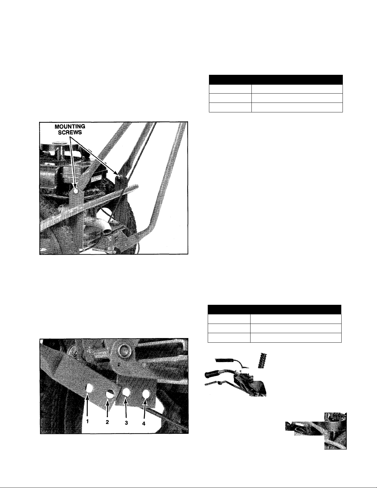
F. Securely tighten the two upper handlebar mounting
screws that you finger-tightened in Step C.
G. On the 22" mower (5HP engine) only, use a plastic
tie to secure the blade drive control cable (the thick
black cable attached to the blade drive control on the
left handlebar) to the center handlebar brace. Locate
the tie 3" to 4" above the bend at the lower end of the
center brace.
NOTE: For future handlebar height adjustments, refer
to the instructions found in Section 5.
Photo 2-3: Attach left and right handlebars.
C. Install two 3/4" long screws through the mounting
holes with the screw heads facing outside. Add 3/8"
lockwashers and hex nuts and tighten both screws
finger-tight.
D. There are two height adjustment holes at the bottom
of the center handlebar brace and two adjustment
holes in the height adjustment bracket which is welded
to the mower frame. See Photo 2-4. The four holes
allow you to choose three different handlebar height
positions: LOW, MEDIUM and HIGH.
STEP 3: Attach Wheel Drive Control Rod (Self-Propelled Models Only)
A. Parts Needed: (1) Clevis Pin, (1) Spring Clip.
B. One end of the upper wheel drive control rod is
already attached to the wheel drive lever located on
the right side of the handlebars. See Photo 2-5. The
clevis at the bottom of the control rod must be attached
to the bellcrank located at the rear of the mower. See
Photo 2-6.
C. There are three positioning holes in the bellcrank
that are identified in Photo 2-6 with the letters “H”, “M”
and “L”. As shown in the chart below, the clevis must
be installed in the correct bellcrank hole, relative to the
height setting of the handlebars.
USE HOLE
“H”
“M”
iilJl
IF HANDLEBARS ARE IN:
HIGHEST HEIGHT SETTING
MEDIUM HANDLEBAR SETTING
LOWEST HANDLEBAR SETTING
ff -«-WHEEL DRIVE LEVER
'i.'
Photo 2-4: Handlebar height adjustment holes. (Bell-
crank plate on self-propelled model has been rotated
upward for photo clarity.)
WHEEL DRIVE
CONTROL ROD
1
Photo 2-5: Wheel drive lever and upper control rod.
Page 9
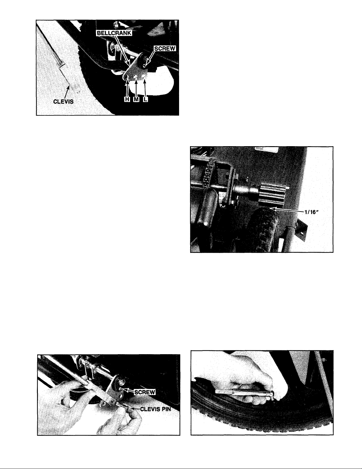
Photo 2-6: Clevis attaches to bellcrank. Do not remove
alignment screw and nut during attachment steps.
IMPOFnANT
Whenever the handlebar height is changed, the posi
tion of the control rod clevis must be changed accord
ingly. Moving the handlebars changes the tension on the
upper control rod and this tension must be adjusted by
relocating the clevis in the appropriate bellcrank hole.
Refer to the “Handlebar Height Adjustment" instructions
in Section 5 for the correct procedure to follow.
D. Before the mower left the factory, the bellcrank was
rotated upward and secured in place with a #10-24 x
5/8" long Phillips head screw and #10 lockwasher/nut.
See Photo 2-6. This aligns the bellcrank. The bellcrank
must be aligned in this manner every time the control
rod clevis is relocated to a different bellcrank position
ing hole. Do not remove the screw and lockwasher/nut
at this time.
NOTE: If the screw and lockwasher/nut has been
removed, rotate the bellcrank upward and reinstall the
screw and lockwasher/nut.
E. Slide the arms of the clevis over the bellcrank, push
ing the clevis forward as far as it will go.
F. Pull the handle on the wheel drive lever all the way
back into its most reanward position and, while holding
the lever in this position, try to align the clevis hole with
the appropriate bellcrank hole. Do not let the wheel
drive lever move from its most rearward position while
you are moving the clevis.
G. If the holes line up, insert the clevis pin through the
right side of the clevis and secure it with the spring
clip. See Photo 2-7. If the holes do not line up, remove
the clevis from the bellcrank and adjust the clevis by
rotating it up or down the control rod.
H. Repeat Steps E, F and G until the holes are
aligned.
I. Remove the screw and lockwasher/nut (shown in
Photos 2-6 & 2-7) from the bellcrank alignment holes.
You may have to jiggle the bellcrank slightly to free
them. Be sure to save the screw and lockwasher/nut
for any future readjustments of the upper wheel drive
control rod.
J. At this time, check to see that the wheel drive rollers
are not touching the rear tires. See Photo 2-8. With the
wheel drive lever in the upward, NEUTRAL position,
there should be a minimum clearance of 1/16" be
tween the rollers and the tires. This clearance ensures
that the rollers will not drive the wheels when the wheel
drive lever is in NEUTRAL. If there is not at least 1 /16"
of clearance, an adjustment must be made before the
engine is started. Please refer to Section 5, “Adjusting
Wheel Drive Traction” for the necessary adjustment
procedure.
Photo 2-8: Check for minimum clearance of 1/16"
between rollers and tires. (Belt/pulley safety cover re
moved for photo clarity.)
STEP 4: Check Tire Pressure
A. Use a pocket-type tire pressure gage to check the
inflation pressures in the rear tires. See Photo 2-9. The
tires should be equally inflated to between 25-30 psi.
B. Incorrect or unequal air pressure can result in ab
normal tire wear and difficult steering. On self-propelled
models, it can result in poor traction between the wheel
drive rollers and the tires. For best results, check the
inflation pressures after every 10 hours of operation or
once a week, whichever occurs sooner.
Photo 2-7: Secure clevis with clevis pin and spring clip. Photo 2-9: Check tire pressures in rear tires.
Page 10
STEP 5: Attach Mower Discharge Deflector
CAUTION
• The discharge deflector must be installed before
operating the mower.
• Before installing the deflector, disconnect the
spark plug wire and keep the wire away from
the spark plug to prevent accidental starting.
• It will be necessary to reach below the blade
housing to install the discharge deflector.
Before doing so. put on heavy gloves to protect
your hands from the sharpened mower blade.
A. Parts Needed: (1) Discharge Deflector, (4) 1/4"-20
X 5/8" long Carriage Bolts, (4) 1/4" Lockwashers,
(4) 1 /4"-20 Hex Nuts.
B. It will be easier to install the deflector if you raise
the front of the mower a few inches off the ground and
then block the rear wheels.
C. Place the discharge deflector on the right side of
the mower deck so that the two square holes on the top
of the deflector are aligned with the square holes in the
top of the mower deck. Make sure that the right side of
the deflector overlaps the front wrap of the mower deck
and the left side of the deflector overlaps the rear mount
ing bracket. See Photo 2-10.
D. Insert two 5/8" carriage bolts down through the
holes in the top of the deflector and loosely attach 1 /4"
lockwashers and hex nuts. See Photo 2-10.
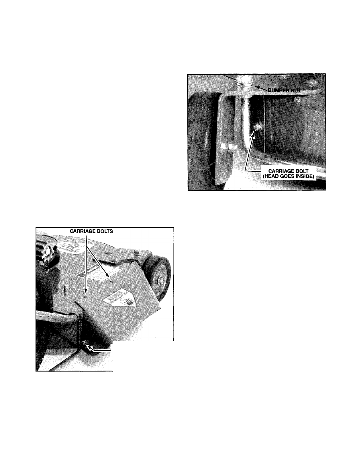
side of the mower deck out through the holes in the
front wrap and the deflector. Loosely attach a 114" lockwasher and hex nut. See Photo 2-11. If necessary, loosen
the bumper nut (shown in Photo 2-11) to gain clearance
for the carriage bolt and nut. After adding the bolt and
nut, securely tighten the bumper nut.
G. Using a 7/16" wrench, tighten all four carriage bolts
securely.
Photo 2-11: Location of fourth carriage bolt.
STEP 6: Add Oil to Engine Crankcase
CARRIAGE BOLT
(HEAD GOES INSIDE)
Photo 2-10: Location of three carriage bolts. (Belt/pulley
safety cover removed for photo clarity.)
E. Insert a 5/8" carriage bolt from the inside of the
mower deck out through the holes in the bottom, left
side of the mounting bracket and the deflector. Loosely
attach a 114" lockwasher and hex nut. See Photo 2-10.
F. On the bottom, right side of the deflector (behind
the front wheel), insert a 5/8" carriage bolt from the in
CAUTION: The engine was shipped to you
“dry", and oil must be added to the crank
O
case before the engine is started to avoid damag
ing the engine.
A. Make sure that the engine is level.
B. Use a high quality detergent oil classified "For
Service; SE, SF, or SG." Above 40°F, use SAE 30.
From 0° to 40°F, use 5W-30 or 10W-30. (See the
engine owner's pamphlet for synthetic oil
recommendations.) No special additives should be
added to the oil. DO NOT MIX OIL WITH
GASOLINE.
C. The 5HP engine (22" mower) requires
approximately 20 ounces; the 8HP engine (24"
mower) requires approximately 36 ounces.
D. Clean the area around the oil fill hole before
removing the oil fill plug or dipstick.
IMPORTANT: Always stop engine before adding oil.
E. 8 HP ENGINE: Remove the dipstick by rotating it
counterclockwise. See Photo 2-12. Using a clean funnel,
slowly pour oil into the filler neck. While adding oil, fre
quently check the level by replacing the dipstick and
rotating the cap until it is secure. Then remove the dip
stick and check the oil level by reading the dipstick
markings (wipe the dipstick with a clean rag each time
before replacing it). Stop adding oil when the level
reaches the FULL mark. Do not overfill. ALWAYS MAIN
TAIN THE OIL LEVEL AT THE FULL MARK ON THE
DIPSTICK.
8
Page 11
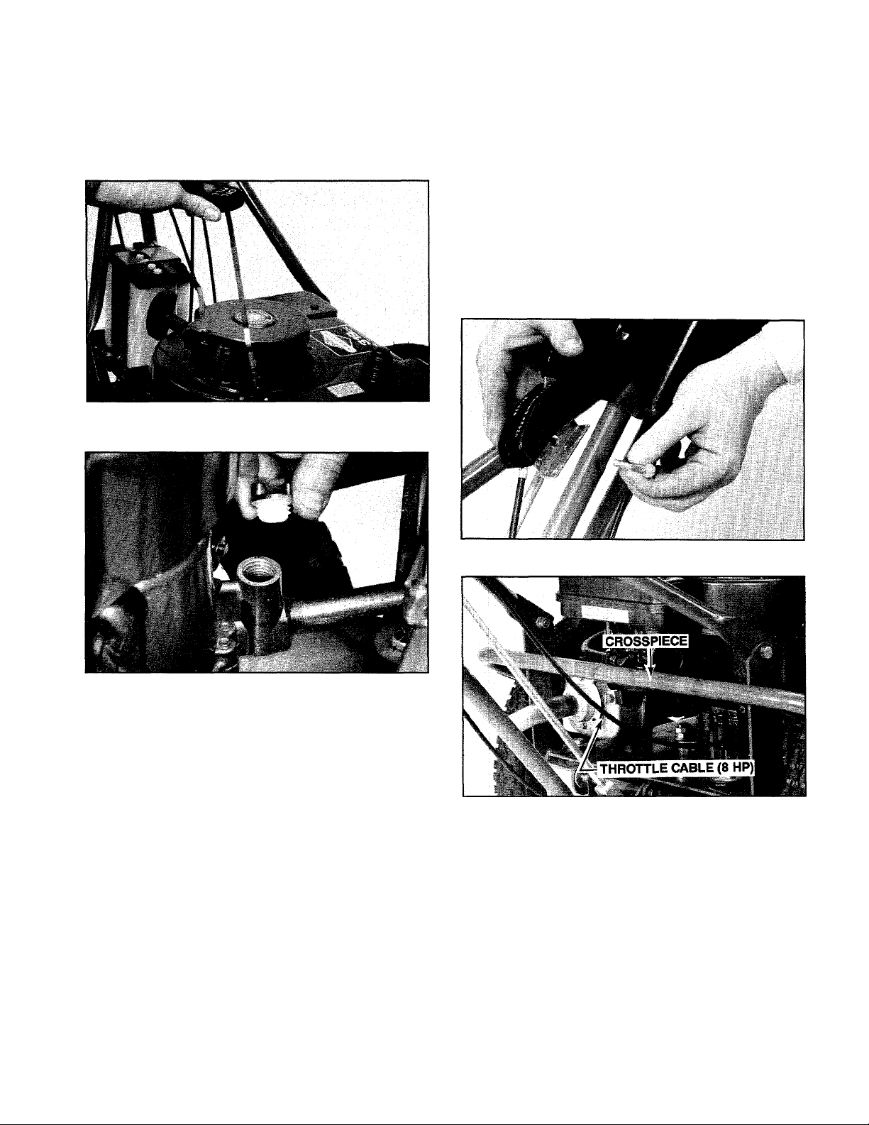
F. 5 HP ENGINE: Remove the oil fill cap by rotating it
counterclockwise. See Photo 2-13. Using a clean fun
nel, slowly add oil until it reaches the point of overflow
ing at the oil fill hole. ALWAYS MAINTAIN THE OIL
LEVEL AT THE POINT OF OVERFLOWING.
G. After adding oil, securely replace the oil fill cap or
the dipstick.
Photo 2-12: Oil fill hole on 8 HP engine.
NOTE: On the 22" mower (5 HP engine) the throttle
cable should be routed above the tubular frame cross
piece located behind the engine; on the 24" mower {8
HP engine) the cable should be below the crosspiece.
See Photo 2-15.
C. Insert a 1 1/2" long screw through the handlebar
and into the metal clamp that is attached to the throttle
control. Add a 1/4" lockwasher and hex nut and
tighten securely using two 7/16" wrenches.
D. On the 24" mower only, use a plastic tie to secure
the throttle control cable and the blade control cable
(the thick, black cable that is attached to the blade drive
control on the left handlebar) to the center handlebar
brace. Locate the tie approximately in the middle of the
center brace.
Photo 2-13: Oil fill hole on 5 HP engine.
IMPORTANT
Check the oil level each time before starting the
engine and after each 5 hours of continuous opera
tion.
Change the oil after the first 5 operating hours and
every 25 hours thereafter. Change the oil more fre
quently in extremely dusty or dirty conditions.
Clean the air cleaner after every 25 operating hours,
or sooner under extremely dusty or dirty operating
conditions.
STEP 7: Attach Engine Throttle Control
A. Parts Needed: (1) 1/4"-20 x 1 1/2" long Hex Hd.
Screw, (1) 1 /4" Lockwasher, (1) 1 /4"-20 Hex Nut, (1)
Plastic Tie (for 24" Mower Only).
B. Uncoil the throttle cable and position the throttle
control on the inside edge of the left handlebar as
shown in Photo 2-14.
Photo 2-14: Install engine throttle control.
Photo 2-15: Throttle cable goes below crosspiece on 8
HP engine (as shown above), and above crosspiece
on 5 HP engine.
IMPORTANT
This completes the mower assembly steps if you have a
recoil (rope pull) starting engine. If you have an electric
(key switch) starting engine, please continue with the
following electric start assembly steps.
CAUTION: To avoid personal injury, carefully
read and follow all of the Safety, Controls,
B
and Operating instructions in this manual and in
the separate engine owner's pamphlet before
attempting to start the engine or operate the mower.
Page 12

ELECTRIC START ASSEMBLY STEPS:
IMPORTANT
Your new battery must be activated with eiectroiyte and
fuiiy charged before placing it in service.
The optional electric start system includes a 12-volt
side-vented battery, a key switch ignition system, a
solenoid, a starter motor (attached to the engine), and
the cables and wires that connect the electrical
system. A built-in recharging circuit automatically
recharges the battery during mower operation.
The following steps explain how to activate and
charge the battery, and how to assemble the electric
start system. For your safety, please follow each step
carefully and observe all of the accompanying Safety
Warnings and Cautions.
DANGER — POISON -
A.
■ CAUSES SEVERE BURNS!
• Electrolyte is a sulfuric acid solution.
• Avoid contact with skin, eyes or clothing.
• To prevent accidents and avoid personal injury,
wear protective clothing, rubber gloves, and
shield eyes with safety goggles.
• Neutralize acid spills with baking soda and
water solution. Neutralize empty container with
baking soda and rinse with watei.
ANTIDOTE: External — Flush with water. Eyes
— Flush with water for 15 minutes ana get prompt
medical attention.
ANTIDOTE: Interna! — Drink large quantities of
water or milk. Follow with milk of magnesia, beat
en eggs, or vegetable oil. Call physician immedi-
KEEP OUT OF REACH OF CHILDREN.
DANGER — BATTERIES PRODUCE
B
• Keep sparks, fiame. cigarettes away.
• Ventilate area when charging or using battery
in enclosed space.
• Make sure venting path of battery is alv/ays
open once battery is filled with acid.
EXPLOSIVE GASES!
B. There may be a sealed plastic tube covering the
vent fitting on the positive (-i-) side of the battery. Be
sure to remove and discard this tube before activating
the battery. See Photo 2-16.
C. Piace battery on level surface and remove all filler
caps. Leave caps off during filling and charging
procedures.
POSITIVE
(+)POST
VENT.
Photo 2-16: Add electrolyte to UPPER LEVEL line.
NEGATIVE
(-)POST
UPPER
LEVEL
LINE
WARNING: Remove metal jev,ielry before
working near the battery or any pari of the
n
electrical system. Failure to do so can cause a
short circuit that could result in electrical burns,
an elect'ical shock, or an explosion of battery
D. Carefully fill the cells with battery grade electrolyte
(1.265 Specific Gravity sulfuric acid) until it reaches
the UPPER LEVEL LINE that is marked on the outside
of the battery case. See Photo 2-16. The temperature of
the battery and the electrolyte should be between 60°F
to 80°F for best results. No water or other liquid should
be added to the battery during this initial activation.
E. Allow the battery to stand for 30 minutes. Then
check each cell and, if necessary, add more electro
lyte until it reaches the UPPER LEVEL LINE. DO NOT
overfill with electrolyte as this may cause electrolyte to
flood over during battery charging.
STEP 1: Activate and Charge the Battery
A. The battery is shipped to you “dry”, and it cannot
be used until it has been activated with electrolyte (bat
tery grade sulfuric acid) and given a proper start-up
charge. Activating a battery with electrolyte is danger
ous work (the acid can eat through clothing and burn
skin) and we therefore strongly recommend that you
take the battery to a reliable service station, battery
store, or farm/outdoor power equipment center where
a trained battery technician can complete the job safe
ly. PLEASE DO NOT ATTEMPT TO ACTIVATE THE
BATTERY YOURSELF UNLESS YOU ARE FULLY EX
PERIENCED IN BATTERY SERVICE WORK!
10
DANGER
A
Batteries generate explosive gases Keep sparks
and flames away from battery at all times.
Ventilate area when charging or using battery
in enclosed space.
We recommend that the battery not be left on
charge while unattended (the charging time
need not be continuous).
Carefully follow charging instructions and
Safety Rules provided by the manufacturer of
the charging equipment being used.
Page 13

F. To obtain maximum starting capacity and longest
life, the battery must be fully charged at a rate of 1 to 2
amperes until all cells are gassing freely. (To determine
this, WEAR SAFETY GOGGLES and use a flashlight
to look down into each cell while the battery is being
charged. When gassing freely, the surface of the liquid
electrolyte should be covered with tiny bubbles). The
total charging time should not exceed 12 hours.
CAUTION: Do not charge the battery at a
rate higher than 1 to 2 amperes. Higher
®
amperages can generate excessive heat and gas
sing, permanently damaging the battery.
G. When the battery is fully charged, turn off the
charger and then disconnect the cables. Check the
electrolyte levels, and if necessary add distilled or
demineralized water until it just reaches the UPPER
LEVEL LINE.
H. Replace the filler caps and use a baking soda and
water solution to wash off any electrolyte which may
have spilled on the battery.
Photo 2-17: Install battery mounting bracket.
IMPORTANT
When the battery will not be used for extended periods
(such as during the winter months), the foiiowing
charging scheduie should be followed:
a. Charge the battery before prolonged storage.
b. Charge the battery after prolonged storage.
Please refer to Section 5 of this manual for battery
maintenance and recharging instrucdons.
STEP 2: Install Battery Mounting Bracket
A. Parts Needed: (2) 1 /4"-20 x 1 1 /4" long Hex Hd.
Screws, (2) 1/4"-20" Locknuts, (1) Battery Mounting
Bracket.
B. The battery mounting bracket must be attached to
the mower’s frame and engine mounting platform at
the three locations shown in Photo 2-17.
C. Using two 9/16" wrenches, remove the 1 7/8" long
hex hd. screw, 3/8" lockwasher, and 3/8" hex nut from
the right side of the engine mounting platform. See
Photo 2-17. Save this hardware.
D. Align the two holes in the top, front of the mounting
bracket with the two holes in the mower frame cross
piece. Insert the two 1 1 /4" long screws down through
the bracket and frame and loosely attach the two 1 /4"
locknuts.
E. Align the hole at the bottom of the battery bracket
support leg with the hole in the bottom of the engine
mounting platform (leg goes below platform). Replace
the 1 7/8" long screw, add the lockwasher and nut,
and tighten securely.
F. Now return to the two upper mounting screws and
tighten them securely using two 7/16" wrenches.
STEP 3: Connect Battery Recharging Line
A. Parts Needed: (1) Plastic tie.
B. The battery recharging line is a thin red wire, approx
imately 12" long. One end is already connected to the
upper stud on the solenoid (the solenoid is a black,
can-like device that is mounted on the battery bracket
support leg). On the unattached end of the line there is
a white plastic bayonet terminal.
C. Bring the recharging line over to the right side of
the engine and plug the white terminal into the red term
inal that is attached to the engine with black wires. Push
the terminals firmly together. See Photo 2-18 or 2-19.
Photo 2-18: Connect recharging line on 22" (5HP
engine) mower.
11
Page 14

Photo 2-19: Connect recharging line on 24" (8HP en
gine) mower. (Wheel removed for photo clarity).
D. Use a plastic tie to secure the recharging line to the
strut. See Photo 2-20.
Photo 2-21: Attach starter motor cable to lower stud oh
solenoid.
STEP 5: Attach Ignition Ground Wire
A. The ignition ground wire is a thin green wire that
leads from the key switch wiring harness (the wiring
harness also contains a red and a white wire).
B. At the rear of the engine, remove the nut from the
engine ground stud, attach the wire terminal, and re
place the nut securely. See Photo 2-22 or 2-23.
Photo 2-20: Add plastic tie to recharging line (wheel
removed for clarity).
STEP 4: Attach Starter Motor Cable
A. Parts Needed: (1) 5/16"-24 Hex Nut, (1) 5/16" Lock-
washer.
B. The starter motor cable is a thick red cable, approx
imately 20" long. One end is already attached to the
starter motor at the front, right side of the engine.
C. Bring the cable terminal over to the solenoid that is
mounted on the battery bracket support leg. As shown
in Photo 2-21, attach the cable terminal to the lower
stud on the solenoid and add the 5/16" lockwasher and
5/16" hex nut. Tighten the hex nut securely to ensure a
good electrical contact.
12
Photo 2-22: Attach ignition ground wire on 22" (5HP
engine) mower.
Photo 2-23: Attach ignition ground wire on 24" (8HP
engine) mower.
Page 15

STEP 6: Attach Vent Tube to Battery
A. Parts Needed; (1) Vent Tube (shipped in battery
carton).
B. Attach the long, clear plastic vent tube over the
vent fitting on the positive ( + ) side of the battery. See
Photo 2-24.
Photo 2-24: Attach vent tube to battery. Photo 2-25: Install battery and hold-down clamp.
STEP 7: Install Battery and Hold-Down Clamp
A. Parts Needed: (1) Hold-Down Clamp, (2) 1/4"-20 x 1"
long Hex Hd. Screws, (2) 1/4"-20 Locknuts.
B. Place the battery on the mounting bracket exactly
as shown in Photo 2-25. Make sure that the positive (-t-)
post on the battery is facing the engine.
C. Run the plastic vent tube straight down the side of
the battery so that the end is pointing toward the ground.
D. Position the hold-down clamp over the battery ex
actly as shown in Photo 2-25, making sure that the large
hole in one side of the clamp is on the left side of the
battery.
E. Fasten the two sides of the clamp to the bracket by
inserting the two 1" long screws up through the mount
ing holes. Add 1/4" locknuts and tighten securely using
two 7/16" wrenches. The clamp should be tight enough
to prevent the battery from moving, but do not overtigh
ten the screws, which would bend the tabs on the clamp.
WARNING
ik
• Do not touch the positive (+) battery post and
any other surrounding metal with tools, jewelry,
or other metal objects. Doing so can cause a
short circuit that could result in electrical burns,
an electrical shock, or an explosion of battery
STEP 8: Attach Positive (-f) Battery Cabie
A. Parts Needed: (1) 1/4"-20 x 1/2" long Battery Bolt,
(1) 1/4"-20 Hex Nut (shipped in battery carton). Note;
Battery bolts and nuts are metric sizes. The sizes given
above are in U.S. size equivalents.
B. The positive ( + ) battery cabie is a thick red cable,
approximately 14" long. One end is already attached
to the upper stud on the solenoid. There is a rubber in
sulating boot located on the cable.
C. Place the battery nut on the inside of the battery
positive (-i-) post and the cable terminal on the outside
of the post. Install the battery bolt securely using a Phil
lips head screwdriver. See Photo 2-26.
D. Slide the rubber boot over the battery post, making
sure that it covers the post completely. If necessary,
use a screwdriver with a wide, flat tip to help seat the
boot between the battery nut and the battery case.
• Install the battery exactly as shown in Photo
2-25. If the battery is installed in reverse, the
battery and other electrical system parts will
be damaged.
• Make certain that the vent tube is not crimped,
pinched, or folded anywhere along its length.
Improper venting could result in a battery ex
plosion.
Photo 2-26: Attach positive (-i-) battery cable.
13
Page 16

STEP 9: Attach Negative (-) Ground Wire and Negative (-) Battery Cabie
A. Parts Needed: (1) Va”-20 x Уг" long Battery Bolt, (1)
1/4 "-20 Hex Nut (shipped in battery carton).
B. The negative (-) ground wire is a thin black wire,
approximately 11" long. One end is already connected
to the upper bolt that secures the solenoid to the battery
bracket support leg.
C. The negative (-) battery cable is a thick black cable,
approximately 22" long. One end is already connected
to the engine mounting screw on the left side, rear of
the engine.
D. Place the battery nut on the inside of the battery
negative (-) post and position the wire and cable ter
minals on the outside of the post. Install the battery
bolt securely using a phillips head screwdriver. See
Photo 2-27.
Photo 2-28: Connect receptacle to key switch.
Photo 2-27: Attach negative (-) wire and cable.
STEP 10: Connect Wire Harness Receptacle
to Key Switch
CAUTION: Remove the ignition key from
the key switch before connecting the wire
B
harness receptacle to the switch.
A. Parts Needed: (1) Plastic Tie.
B. Connect the wire harness receptacle (which has
three wires leading out of it) to the bottom of the key
switch assembly. See Photo 2-28. Make certain that the
connection is good and tight.
C. Use a plastic tie to secure the wire harness to the
negative (-) ground wire and negative battery cable as
shown in Photo 2-29.
D. Do not replace the ignition key in the key switch until
you have read all of the Safety, Controls and Operating
instructions in this manual and in the separate engine
owner’s pamphlet.
Photo 2-29: Secure wire, cable and harness with tie.
WARNING
A
Never br.ng a gasoline can near the battery
posts. A short c.rcuit caused oy touching the
positive (■+ ) post and any meta'. could cause
an explosion of the gasoline or of battery gases.
Never attempt to “jump start" the battery with
an automobile battery or its charging system.
Doing so could result in serious personal injury
or property damage from such causes as a
battery explosion, or acid or electrical burns.
To avoid personal injury, always remove the key
from tne switch, disconnect the spark plug v,riro.
and keep the wire away from the spark plug
v;hen leaving the mower unattended or when
the mower is not in use.
To avoid personal injury when servicing the
mower or engine, alv^ays remove the spark plug
w.re from the spark plug and keep the wire away
from the plug. Then disconnect the negative
I -) cable from the battery post and bend it
safely aviay from the battery post.
14
Page 17

SECTION 3
Mower and Engine Controls
Before operating your mower, familiarize yourself with all mower and engine controls. Taking the time now
to understand fully the location, function, and operation of these controls will greatly increase your ability to
operate your mower efficiently and safely.
IMPORTANT
This mower is equipped with a blade brake which is
designed to stop the mower blade within three seconds
after release of the blade control handle. This feature is
required to meet the federally mandated safety stan
dards described in Section 1 of this Manual. Never
tamper with, or attempt to defeat the purpose of this
safety device. Doing so may result in personal injury
through contact with the rotating blade. Check that the
Blade Brake Control System is operating properly. See
the Blade Brake Control Test Procedure described on
Page 34.
MOWER CONTROLS
NOTE: Ail references to “Left” and “Right” are given
from the operator’s position behind the handlebars.
Because the blade brake system stops the blade but
not the engine, you can disengage the biade drive at
anytime without having to stop and then restart the
engine. This feature is particularly useful when you
need to cross gravel drives or rough terrain and you do
not want the rotating blade to throw stones or strike
hidden obstacies.
WHEEL DRIVE LEVER
(Self-Propelled Model)
Photo 3-1: Location of mower controls.
BLADE DRIVE CONTROLS
The blade control handle and blade control are
located on the left handlebar of your mower. See Photo
3-1. These controls are used to engage and disengage
the mower blade.
To engage the blade drive mechanism, first pull the
blade control handle down and hold it against the han
dlebar grip. Then, set the blade control by pushing the
control forward until a distinct “click” is heard. See
Photo 3-2. This action tightens the blade drive belt,
allowing the blade to begin rotating. It also resets a
friction brake mechanism located on the blade spindle
which will stop the blade within three seconds after
you release the biade control handle.
The blade control handle must be depressed against
the handlebar grip in order to keep the blade rotating.
Releasing the blade control handle will disengage the
blade control and stop the blade within the three se
cond safety limit.
BLADE CONTROL HANDLE
WHEEL DRIVE HANDLE
(Self-Propelled Model)
BLADE CONTROL
Photo 3-2: Operation of blade control handle and blade
control.
CAUTION: When starting the engine, the
blade control handle should be in the fully
released position. This position ensures that the
H
blade will not start rotating when the engine starts.
To avoid personal injury, do not engage the blade
drive controls until you are ready to begin mowing.
WARNING: If the blade brake system is dam
aged or maladjusted, the blade may continue
to rotate after you have released the blade control
H
handle. If the blade does not stop within 3 seconds
of release of the blade control handle, move the
engine throttle control to the STOP position.
Immediately refer to the Blade Brake Control
System Test Procedure on Page 34. To avoid per
sonal injury, do not operate the mower until the
Blade Brake Control System is operating properly.
15
Page 18

WHEEL DRIVE CONTROLS (Self-Propelled Models Only)
The wheel drive handle is located below the left side
handlebar grip and the wheel drive lever is located
toward the right side of the handlebars. See Photo 3-1.
These controls are used to engage and disengage
traction drive to the wheels on self-propelled models.
To engage the wheel drive mechanism, first pull the
wheel drive handle up and hold it against the
handlebar grip. Then, push the wheel drive lever all
the way forward until it latches in the fonward position.
See Photo 3-3. This action pulls back the lower wheel
drive control rod which is connected to the wheel fric
tion drive rollers. The rollers then push against the
wheels to propel the mower forward.
The wheel drive handle must be depressed against
the handlebar grip in order to keep the wheels turning.
Releasing the wheel drive handle will disengage the
wheel drive lever, which then disengages the rollers
from the wheels.
For trimming or maneuvering in tight places, you
can disengage the wheel drive (by releasing the wheel
drive handle), and then “creep” the mower forward by
gradually pushing the wheel drive lever forward until
the wheel friction drive rollers contact the wheels. To
stop the fonward motion, simply pull back on the wheel
drive lever.
HEIGHT OF CUT ADJUSTMENT
The cutting height can be adjusted to any of four dif
ferent settings: 1-5/8", 2-1/4", 2-7/8", and 3-1/2".
The cutting height has been set at the factory at the
2-7/8" setting. This cutting height is recommended for
initial mowing in rough terrain as it will minimize the
chances of the blade hitting rocks or other hidden
obstructions (see CAUTION statement below).
To change the cutting height to a higher or lower set
ting, refer to the “Height of Cut Adjustment” instruc
tions in Section 5.
CAUTION: Before mowing, thoroughly in
spect the area where the mower is to be used
B
and remove all stones, sticks, wires, bones, nails
and other foreign objects, to prevent personal in
jury caused by throv^n objects.
ENGINE CONTROLS
The following are descriptions of the controls of your
5 HP or 8 HP Briggs & Stratton Engine. Additional in
formation on the safe, efficient operation of your
engine is given in the engine owner’s pamphlet which
was included in your mower literature package. Please
read that pamphlet carefully.
Photo 3-3: Operation of wheel drive handle and wheel
drive lever.
CAUTION: When starting the engine, the
wheel drive lever should be in the upward.
H
NEUTRAL position. This postion ensures that
the wheels will not starl turning when the engine
starts. To avoid personal injury, do not engage the
wheel orive lever uniti you are reaoy to move the
CAUTION: To avoid personal injury, do not
attempt to start your engine at this time.
B
Complete starting instructions for your mowe' are
provided in Section 4. ■ 'Operating Instructions.”
ENGINE THROTTLE CONTROL
On all models, the engine throttle control is located
on the left handlebar. See Photo 3-4. This control
operates a full range of engine speeds. It also activates
the engine choke control when starting the engine,
and stops the engine by grounding out the ignition.
HANDLEBAR HEIGHT ADJUSTMENT
The handlebars can be adjusted to any of three dif
ferent height settings; LOW, MEDIUM and HIGH.
To change the handlebar height, refer to the “Han
dlebar Height Adjustment” instructions found in Sec
tion 5.
16
Photo 3-4: Engine throttle control settings.
Page 19

There are three operating positions identified on the
throttle control: CHOKE, F-S (Fast-Slow), and STOP.
The Fast and Slow settings are provided with detent
type stops that “catch” the lever when those settings
are engaged. To move the lever out of the detent stops,
push the lever a short distance to the right.
Before starting the engine, always make sure that
the blade drive and wheel drive controls are disengag
ed. Then, move the throttle lever all the way forward
(past the Fast detent stop) to the CHOKE position. As
soon as the engine starts, gradually pull the lever back
to the Slow detent stop. Do not leave the throttle in the
choke position. Doing so could harm your engine.
NOTE: A warm engine requires less choking than a
cold engine.
Once the engine is sufficiently warm, move the lever
to the desired engine speed for your particular mowing
task. The engine is designed to be operated at full
speed to give you the best cut and fastest traction drive
(on self-propelled models). However, if preferred,
slower speeds can be used.
To stop the engine, release the blade and wheel
drive control handles, put the engine throttle lever in
the Slow position, and then pull the throttle lever all the
way back to the STOP position.
FUEL SHUT-OFF VALVE
(8 HP Engine Only)
The 8 HP (24" mower) engine is equipped with a
fuel shut-off valve. The valve is located on the back of
the engine below the air cleaner assembly. See Photo
3-5.
To shut off the fuel flow to the carburetor, turn the
valve clockwise until it stops turning. To open, turn the
valve counterclockwise several turns. Always remember
to open the fuel valve before attempting to start the
engine.
NOTE: Close the fuel shut-off valve when the engine is
transported to prevent fuel leakage.
Photo 3-6: Engine recoil starter rope (5 HP engine
shown).
To start the engine, first place your left hand on the
right side handlebar grip to help stabilize the mower.
Then grasp the starter rope handle with your right
hand and pull the rope out slowly until it is harder to
pull because of engine compression. Next, pull the
rope with a rapid, continuous, full-arm stroke. Do not
let the starter rope snap back against the rope guide.
Let the rope rewind slowly.
KEY SWITCH STARTER (Electric Start Engine Only)
The key switch starter for electric start engines is
located on the right handlebar. See Photo 3-7. There
are three operating positions identified on the switch:
OFF, RUN, and START.
Photo 3-5: Fuel shut-off valve (8 HP engine).
ENGINE RECOIL STARTER
On all models, the recoil starter rope handle is
located on top of the engine, on the right side as view
ed from the operator’s position behind the handlebars.
See Photo 3-6.
Photo 3-7: Key switch starter
To start the engine, first insert the key firmly into the
slot. Then, turn the key to the START position. Do not
hold the key in the start position for longer than a few
seconds. Prolonged cranking can damage the starter
motor if cranked more than 15 seconds per minute.
When the engine starts, release the key and It will
automatically return to the RUN position.
There are two ways to stop the electric start engine:
1. Release the blade control and wheel drive handles,
put the engine throttle lever in the SLOW position, and
then pull the throttle lever all the way back to the STOP
position. Turn the key to the OFF position and remove
the key.
2. Release the blade control and wheel drive handles,
then put the engine throttle lever in the SLOW posi
tion. Turn the key to the OFF position and remove the
key.
17
Page 20

SECTION 4
Operating Instructions
Your TUFF-CUT Mower is very easy to operate and in this Section you wiii find not oniy detaiied operating
instructions, but aiso tips and suggestions to heip you get the greatest possible satisfaction from your mower.
Please read this Section thoroughly before you attempt to start the engine. Then, find a clear area where you
can safely learn to start, stop and maneuver your mower.
IMPORTANT
Before operating your mower, be sure that you have
carefully read and fully understand the “Rules for Safe
Operation” given in Section 1 of this manual, in addition
to those presented in this Section.
PREPARATION BEFORE
STARTING
A. CHECK ENGINE OIL LEVEL. Check the oil level in
the engine crankcase. Do not run the engine unless
the proper oil level is maintained. Refer to Section 2 for
instructions.
IMPORTANT
Check oil level before each use and after each five hours
of continuous operation. Change oil after first five oper
ating hours and every 25 operating hours thereafter.
B. FILL FUEL TANK
1. Remove fuel tank cap and check fuel level (see
Photo 4-1 or 4-2). Clean area around fuel cap before
removing to prevent the entrance of dust, dirt and mois
ture.
2. Use clean, fresh, lead-free, automotive gasoline.
Leaded gasoline may be used if lead-free is not avail
able. (The use of lead-free gasoline results in fewer
combustion deposits and longer valve life.) A minimum
of 77 octane is recommended. DO NOT MIX OIL WITH
GASOLINE.
Photo 4-1: Fuel tank on 5HP engine (22" mower).
Photo 4-2: Fuel tank on 8HP engine (24" mower).
3. Do not fill the fuel tank to the point of overflowing.
Fill to within V2" of top of fuel tank to prevent spills and
to allow for fuel expansion. The fuel tank capacity is 2
quarts on the 5HP engine and 3 quarts on the 8HP
engine.
4. Replace the fuel cap securely before starting the
engine.
DANGER: Gasoline is highly flammable and
its vapors are explosive. Handle with extreme
n
care. Never fill tank when engine is running or
still hot from operation. Do not allow open flame,
matches or smoking in area. Do not fill tank in
doors or in poorly ventilated area. Wipe any spills
and move mower away from gasoline fumes before
starting engine. Use an approved container.
C. CHECK AIR CLEANER. Check the cleanliness of
the oil foam air cleaner and service it if necessary. Refer
to the engine owner’s pamphlet for instructions.
D. CHECK NUTS AND BOLTS FOR TIGHTNESS.
Check all nuts and bolts for tightness and keep them
tightened securely at all times.
E. CHECK TIRE PRESSURE. Make sure that the rear
tires are inflated equally to between 25-30 psi.
F. CHECK CUTTING HEIGHT. Check that the wheels
are adjusted for the desired cutting height as described
in Section 5.
G. ATTACH SPARK PLUG. Be sure that the spark plug
wire is securely attached to the spark plug.
18
Page 21

H. CHECK BATTERY (Electric Start Models). Check
that the battery is properly filled and that all electrical
connections are clean and tight. Refer to Section 5 for
instructions.
IMPORTANT
At the start of each season and after every 10 operating
hours, perform the Blade Brake Control Test Procedure
described on Page 34.
TO START THE ENGINE
WARNING: Never run the engine in an en
closed or poorly ventilated area Engine ex
H
haust contains carbon monoxide, an odorless and
deadly gas.
A. Be certain that the blade control handle and the
wheel drive handle (on self-propelled models) are in the
disengaged (reieased) position. See Photo 4-3.
for longer than a few seconds. Prolonged cranking can
damage the starter motor if cranked more than 15
seconds per minute. Release the key when the engine
starts.
NOTE: If necessary, the electric start engine can be
started with the recoil starter rope. See Section 5 for
detailed instructions.
F. If your engine does not start in four or five tries, let
the engine set for 10 minutes and then repeat the start
ing procedure.
G. As soon as the engine starts, move the engine throt
tle lever gradually to the SLOW (S) setting and allow
the engine to warm up. Then, move the lever to the
desired speed for your mowing task.
IMPORTANT
Do not leave the throttle lever in the CHOKE position.
Doing so could harm your engine.
TO ENGAGE THE BLADE
A. When you are ready to begin mowing, first pull the
blade control handle down and hold it against the han
dlebar grip. Then push the blade control forward until a
distinct “click” is heard. See Photo 4-4.
Photo 4-3: Release blade control and wheel drive han
dles before starting engine.
B. On 8HP engines (24" mower), open the fuel shut
off valve.
C. Set the engine throttle lever at the CHOKE position.
NOTE: A warm engine requires less choking than a
coid engine.
D. For recoil start engines, place your left hand on the
right side handlebar grip to help stabilize the mower.
Then grasp the starter rope handle with your right hand
and pull the rope out slowly until it is harder to pull be
cause of engine compression. Next, pull the rope with
a rapid, continuous, fuil-arm stroke. Do not let the starter
rope snap back against the rope guide. Let the rope
rewind slowly.
CAUTION: To avoid personal injury, be sure
that there are no obstacles behind you when
O
you pull out the starter rope handle
E. For electric start engines, turn the key switch to the
START position. Do not hold the key in the start position
Photo 4-4: To engage the blade drive.
DANGER: To avoid personal injury from
rotating blade and thrown objects, keep
B
face, hands and feet clear of the mower blade
and discharge opening at all times.
B. Increase or decrease the engine speed to adjust
the blade speed. For best cutting results, the blade
should be operated with the engine at full or nearly full
throttle.
C. TO STOP THE BLADE, release the blade control
handle completely from its position against the handle
bar grip.
IMPORTANT
At the start of each season and after every 10 operating
hours, perform the Blade Brake Control Test Procedure
described on Page 34.
19
Page 22

CAUTION: To avoid personal injury, disen
gage the cutting blade before crossing gravel
B
drives, roads, or sidewalks to prevent the blade
from throwing stories or other hazardous objects.
TO ENGAGE THE WHEELS
(Self-Propelled Models Only)
A. Pull the wheel drive handle up and hold it against
the handlebar grip. Then push the wheel drive lever
forward until it latches in the forward position. See Photo
4-5.
Photo 4-5: To engage the wheel drive on self-propelled
models.
B. Increase or decrease the engine speed to adjust the
ground speed.
C. TO STOP THE WHEELS, release the wheel drive
handle from its position against the handlebar grip.
TO STOP THE ENGINE
A. Release the blade control handle and the wheel
drive handle (on self-propelled models).
B. Put the engine throttle lever in the Slow (S) posi
tion.
C. Pull the engine throttle lever all the way back to the
STOP position (and turn the key to OFF on electric start
models).
CAUTION: To prevent injury from accidental
or unauthorized starting, disconnect the
^
spark plug wire and move the wire away from tho
olug when leaving the mower unattended or Vi/hen
the mower is not in use. Always remove the key
from the switch on electric start models.
OPERATING THE MOWER
Use the following tips to help you in getting the best
possible use from your TUFF-CUT® Mower.
A. Although your TUFF-CUT® Mower is wider and
longer than ordinary mowers, its large rear wheels and
perfect balance make it surprisingly easy to maneuver.
Become familiar with your mower by first practicing
with it in a clear, level section of your property, with the
engine throttle control set at a slower engine speed
setting. Practice engaging and disengaging the con
trols until you are completely comfortable with their
ease and manner of operation. Remember, with the
self-propelled model, let the powered wheels do the
work while you simply guide the mower along.
B. Making turns is exceptionally easy because the
weight of the engine is centered over the rear wheels.
Thus, you need only apply light downward pressure on
the handlebars to tip up the front of the mower prior to
making a turn. On self-propelled models, it’s easier to
make a turn if you first disengage the powered wheels
by releasing the wheel drive handle. With the wheel
drive disengaged, the inside wheel will pivot in place
while the outside wheel rolls freely. After completing
your turn, simply reengage power to the wheels and
continue with your mowing.
WARNING*
TO HELP AVOID PERSONAL INJURY:
Exercise extreme caution when changing direc
tion on slopes to prevent loss of control, slip
ping or falling.
When mowing or turning on a slope with a self-
propelled mower, keep the wheel drive lever
ENGAGED until you aie sure that you have
complete control of the mower. Failure to do so
could result in loss of control of the mower.
Do not mow excessively steep slopes.
C. For precision trimming with the self-propelled mower,
simply disengage the powered wheels by releasing the
wheel drive handle. Then inch the mower forward by
gradually pushing the “feather-touch” wheel drive lever
forward until the drive cogs contact the wheels. To stop,
pull back on the wheel drive lever.
D. When cutting tall growth, or if you are on uneven
terrain, use the highest cut setting. Then gradually
reduce to the desired cutting height over the course of
2 or 3 mowings. Go easy in extra tough grass or weeds
as forcing the mower tends to make it slow down or stall.
E. Keep the blade sharp. A dull blade will tear, bruise
and split the ends of grass.
F. Vary your cutting pattern from week to week. This
helps to prevent matting and graining of the grass.
G. Always trim using the left side of the mower, as the
discharge deflector is on the right side of the machine.
Mow around obstacles in a counterclockwise direction
(viewed from the operator’s position). Also, mow with the
discharge deflector pointed away from the obstacles on
the first two passes. Then, reverse the direction. This
will reduce the chances of damage to property from
any thrown objects.
H. When mowing alongside a street or walk, mow with
the discharge deflector pointed onto your own property
(away from the street or walk). This will eliminate the
need to sweep clippings from the sidewalks, etc.
i. Mow ditches in the direction of the ditch. This will
result in debris and clippings being discharged into
the ditch. Mow both sides of the ditch first, and then
mow the bottom. When mowing ditches, watch out for
cans, bottles, or other debris which could become dan
gerous high-speed projectiles.
J. While mowing, never point the discharge deflector
at any person at any time.
20
Page 23

SECTION 5
Maintenance and AcMustments
CAUTION; To avoid personal injury stop
the engine, disconnect the spark plug wire,
S
keep the wire away from the soark plug, and let
tne engine ana muffler cool down before inspect
ing O’’ servicing the mower or engine.
RECOMMENDED MAINTENANCE INTERVALS
Every 10
Maintenance
Procedure:
Check blade for tightness
Inspect nuts & bolts for tightness
Inspect operator controls
Clean underside of mower and inside of
discharge chute
Inspect blade for sharpness
Inspect electric start wires and cables
Inspect electrolyte level in battery
Recharge battery
Lubricate traction drive chain, linkages,
pivot points, throttle control cable, and
wheel mounting bolts and studs
Check tension on wheel drive belt and
chain
Check tension on blade drive belt
Check tire pressure
Perform the Blade Brake Control
3-second Stop Test described on
Page 34
Sharpen or replace blade
ENGINE
Inspect engine crankcase oil level
Inspect throttle cable
Clean air filter
Change engine crankcase oil I
Adjust carburetor
Cooling system maintenance
Clean engine !
Clean and reset spark plug
Every
Use
•
•
•
•
•
•
•
•
Operating
Hours
•
•
•
•
•
•
As
Noted
Before and after prolonged storage
Or once a week, whichever is sooner.
At the start of each season and after
every 10 operating hours.
Whenever damaged, out of
balance, or dull
And after every 5 hours of continuous
operation
At least every 25 operating hours —
see engine owner’s pamphlet.
After 5 break-in operating hours
and every 25 hours thereafter
As required — see engine
owner’s pamphlet
See engine owner’s pamphlet
See engine owner’s pamphlet
See engine owner’s pamphlet
21
Page 24

MOWER MAINTENANCE
ADJUSTING WHEEL DRIVE TRACTION (Self-Propelled Models Only)
On self-propelled mowers, there are two friction
drive rollers located in front of the rear wheels. See
Photo 5-1 or 5-2. These rollers propel the mower for
ward by pressing against the tires.
When the wheel drive lever is in the upright,
NEUTRAL position, the rollers on 22" mowers should
be approximately 3/16" away from the crown (highest
point) of the tires. On 24" mowers, the clearance should
be approximately 1 /8". These two settings should pro
vide adequate tire deflection (3/8" and 7/16" respec
tively) for most mowing conditions. However, if extra
traction is ever needed, the clearance between the
rollers and the tires can be adjusted to a MINIMUM of
1/16", which will result in a tire deflection of 1/2".
NOTE: Use the minimum amount of tire deflection that
will ensure adequate traction for the job at hand. Doing
so will result in less wear on the tires and the rollers.
Follow the simple steps on this page to adjust the
wheel drive rollers.
CAUTION: To avoic persona! injury, stop tne
engine, disconnect the spark plug wire, keep
B
the v/ire away from the spark plug, and allow the
engine and muffler :o cool before making reoairs
or adjustments.
A, Make certain that each tire is equally inflated to
between 25-30 psi. Tire pressure is very important in
maintaining correct friction roller tension.
B. Firmly grasp the threaded end of the lower drive
control rod with one hand (to prevent it from springing
forward when you release the clevis pin) and remove
the spring clip and clevis pin that secures the traction
adjustment block to the mounting bracket. See Photo
5-3.
Photo 5-1: Clearance should be 3/16" for 22" mowers.
Photo 5-3: Hold control rod when removing clevis pin.
C. Rotate the adjustment block in a clockwise direc
tion to reduce the clearance between the rollers and
the wheels, or counterclockwise to increase the
distance. See Photo 5-4. A few turns in either direction
is usually all that will be needed for most adjustments.
Photo 5-4: Thread adjustment block clockwise to
reduce roller clearance, or counterclockwise to in
crease clearance.
Photo 5-2: Clearance should be 1 /8" for 24" mowers.
22
D. Align the hole in the top of the adjustment block
with the hole in the mounting bracket and replace the
clevis pin and spring clip.
E. Engage and disengage the wheel drive lever
several times to verify that the correct clearance is ob
tained. If not, repeat Steps B, C and D.
Page 25

HEIGHT OF CUT ADJUSTMENT
The cutting height of your mower has been set at the
factory to the third highest cutting position. This gives
a cutting height of 2-7/8". The cutting height can be
adjusted within a range of 1-5/8" to 3-1/2" (see table
below). To change the cutting height, change the posi
tion of the rear and front wheels according to the follow
ing instructions.
height adjustment holes (A, B, C or D) on both sides.
Be sure that the front and rear wheels are located in
the same relative settings (A, B, C or D).
F. Replace the lockwashers and nuts on the front
wheels, and tighten securely.
G. Remove the props from beneath the blade housing.
H. On self-propelled models only, you must readjust
the wheel friction drive rollers to ensure that the
clearance between the rollers and tires is correct
TOOLS NEEDED: 9/16" and 3/4" Wrenches.
A. Prop up both sides of the mower below the blade
housing, high enough to raise all four wheels off the
ground.
B. On self-propelled models only, disconnect the lower
drive control rod by following Step B of the previous
“Adjusting Wheel Drive Traction” instructions.
C. Using a 9/16" wrench, loosen, but do not remove,
the inside and outside flanged lock nuts that secure
the rear wheels in place. See Figure 5-5. Remove the
wheels and replace them in the same corresponding
slots (A, B, C or D) on both sides.
TOOLS NEEDED: Two 9/16" Wrenches.
A. Install the Phillips screw into the alignment holes
on the bellcrank and bellcrank mounting plate and
attach the nut. This aligns the bellcrank. See Photo 5-6.
Photo 5-6: Align bellcrank with screw and nut.
B. Disconnect the upper drive control rod by removing
the spring clip and clevis pin that secures the control
rod clevis to the bellcrank. See Photo 5-7.
Figure 5-5: Wheel height adjustment positions.
D. Position the inside and outside wheel retaining clips
so that the bent legs are against the unslotted edge of
the height adjustment brackets. Then tighten the in
side and outside flanged lock nuts securely.
E. Using 9/16" and 3/4" wrenches, remove the nut
and lockwasher from each front wheel, leaving the
mounting bolts in place. See Figure 5-5. Remove the
wheels and replace them in the same corresponding
Photo 5-7: Disconnect clevis from bellcrank.
23
Page 26

C. Adjust the handlebars to the desired height by
following Steps D and E of the “Attach Handlebars” in
structions on Page 6.
D. Whenever the handiebar height is changed, the
position of the control rod clevis must be changed accordingiy, reiative to the height position of the handle
bars. To change the clevis to the correct bellcrank hoie,
follow Steps B, C, E, F, G and H of the “Attach Wheel
Drive Control Rod” instructions on Pages 6 and 7.
E. After securing the control rod clevis to the bellcrank
with the clevis pin and spring clip, remove the screw
and nut from the bellcrank alignment holes. Be sure to
save the screw and nut for any future handlebar height
adjustments.
F. With the wheel drive lever in the upright, NEUTRAL
position, check that the clearance between the rollers
and the tires is correct. See “Adjusting Wheel Drive
Traction” on Page 22.
cause excessive vibration which could result in engine
damage, or personal injury if the blade should break.
Photo 5-8: Remove screw and conical washer.
SHARPENING OR REPLACING THE MOWER BLADE
Check the condition of the mower blade before each
use. If it is dull or slightly nicked, it should be sharpened
as explained below. A deformed, cracked, or badly nick
ed blade should be replaced with a new one. While
checking the blade, also check that the blade mounting
screw is tightened securely.
.CAUTION
A<
To avoid porsonni injury, stop the engine, dis
connect the spar< plug wire, keep the wire
away from the spark plug, and allow the engine
and muffler :o coo' before inspecting or servic
ing the blade.
To avoid personal injury from contact with the
sharpened blade, wear heavy gloves or wrap
the blade with ‘.hick rags before working neat it.
To prevent a potential fi''e hazard from possible
gasoline spills, make certain that the area iS
well ventilated and that you keep smokincj
materials, soarks or Fame away.
TOOLS NEEDED: 9/16" Wrench, Flat Metal File.
A. Raise the front of the mower by anchoring the han
dlebars securely or by propping up the mower with stur
dy blocks. On the 8 HP engine only, turn the fuel valve
to the OFF position before tilting the mower back.
B. To remove the blade, hold the blade with one hand
and remove the screw and conical (belleville) washer
using a 9/16" wrench. See Photo 5-8.
C. If the blade needs sharpening, use a file to sharpen
the cutting edge at both ends of the blade. Sharpen
along the original cutting angle, filing in the direction of
the cutting edge only. To maintain proper blade balance,
be sure to remove the same amount of material from
both cutting edges. Check the blade for balance by
balancing it on the round shaft of a pen or pencil. If the
blade cannot be balanced properly, it should be
replaced with a new blade. An unbalanced blade can
D. To reinstall the blade, first place the conical washer
on the mounting screw, making certain that the con
cave side (hollowed side) of the washer is facing away
from the head of the screw. See Figure 5-9.
IMPORTANT
Do not apply lubricant of any kind to the screw threads.
The screw must be dry in order to work properly.
E. Place the blade in the support channel of the blade
mounting bracket, making certain that the two air lifts
at each end of the blade are pointing upward, toward
the top of the mower deck.
F. Using your fingers only, tighten the screw finger-
tight while gently rocking the blade up and down to
properly seat the blade.
G. Tighten the screw to 38 to 42 ft. lbs. torque. If you
do not have a torque wrench, use the following method
to ensure that the screw is tightened correctly:
1. Using chalk, a grease marker, or paint, draw a
thin line across one-half of the screw head as
shown in Figure 5-10. Draw a similar reference
line on the washer, directly opposite the line on
the screw.
2. Be sure that the screw is tightened finger-tight
as explained in Step F above. Then using the two
lines as reference marks, tighten the screw VA
turns.
24
Page 27

CHECK BOLTS, SCREWS AND NUTS
Before each use, check all bolts, screws and nuts for
tightness and keep them tightened securely at all times.
LUBRICATION
Clean and add several drops of light oil to the follow
ing points after every 10 operating hours:
1. All linkages and pivot points.
2. Drive chain on self-propelled models.
3. Both ends of the throttle control cable.
4. Wheel mounting bolts and studs.
5. The spring-loaded dowel pin found on the inside
edge of the two friction drive rollers (see Ref. Nos. 100
and 98 in your Parts Catalog for the location of these
two parts). After oiling, rotate the friction drive roilers to
help spread the oil on the pins.
Figure 5-10: If you do not have a torque wrench, tighten
mounting screw as shown above.
H. Remove any rags you may have used to cover the
blade and then lower the front of the mower to the
ground.
I. Reconnect the spark plug wire (and open the fuel
valve on the 8 HP engine) before attempting to start
the engine.
NOTE: Use only a “GRADE 8” screw to mount the
blade. Refer to your Parts Catalog if a replacement
screw is needed.
CLEAN THE MOWER HOUSING AND
DISCHARGE CHUTE
Clean the underside of the mower housing and the
discharge chute after every mowing. More frequent
cleaning may be necessary under heavy cutting con
ditions.
CAUTION: To avoid personal injury, stop the
engine, disconnect the spark plug wire, keep
B
the wire away from the spark plug, and allow the
engine and muffler to cool before cleaning the
mower housing or discharge chute.
WHEEL DRIVE BELT TENSION (Self-Propelled Models Only)
Check the wheel drive belt tension after each 10
hours of operation. Due to normal stretch and wear on
the belt, periodic adjustments may be required. While
checking the tension, also look for obvious signs of
wear such as cracks, cuts or fraying. If the belt is in
poor condition, order a replacement from the Garden
Way Parts Department. This is a special belt made for
your mower and is not available locally.
CAUTION: Stop the engine, disconnect the
spark plug wire, and allovi^ the engine and
B
muffler to cool before inspecting or servicing the
drive belt.
TOOLS NEEDED: 7/16" and 1/2" Wrenches, Flat Blade
Screwdriver, Rubber Mallet.
A. Remove the belt/pulley safety cover by removing
the three hex nuts and two self-tapping screws.
B. To check for correct tension, use your thumb to
press down in the center of the belt as shown in Photo
5-11. The tension is correct if the belt deflects between
V2" to 5/8", under moderate thumb pressure (6-8 lbs.
with V2" deflection).
A. Raise the front of the mower about 6" by propping
up the mower deck with sturdy blocks.
B. Spray the underside of the housing and the dis
charge chute with a garden hose to remove clippings
and dirt (avoid spraying the engine or any electrical
connections).
CHECK TIRE PRESSURE
Use a pocket-type tire pressure gage to check the in
flation pressures in the rear tires. The tires should be
equally Inflated to between 25-30 psi. Check the infla
tion pressures after every 10 hours of operation or once
a week, whichever occurs sooner.
Photo 5-11: Check wheel drive belt tension.
25
Page 28

C. Less than V2" deflection indicates that the belt is
too tight; more than 5/8" deflection indicates that it is
too loose. Use the following procedure if an adjust
ment is required.
D. Using a 1/2" wrench, slightly loosen (about V2 turn)
the three hex nuts that secure the traction drive mount
ing bracket to the mower housing deck. See Photo
5-12.
BRACKET MOUNTING<
NUTS
Photo 5-12: Slightly loosen three hex nuts.
E. To tighten the belt, use a mallet to drive both ends
of the mounting bracket an equal distance toward the
front of the mower. See Photo 5-13. When doing so, tap
one end forward and retighten the nut on that end.
Then, tap the other end forward and retighten the nut.
To loosen the belt, move the bracket backward in a
similar manner. Make certain that both drive rollers are
equally spaced with the wheels.
REPLACING THE WHEEL DRIVE BELT (Self-Propelled Models Only)
CAUTION: To avoid persona! injury, stop the
engine, disconnect the spark plug wire, keep
B
the Vi/ire away from the spark plug, and allow the
engine and muffler to coo^ before replacing the
wheel drive belt.
TOOLS NEEDED: 7/16", 1/2" and two 9/16" Wrenches,
Flat Blade Screwdriver, Rubber Mallet.
A. Remove the belt/pulley safety cover by removing
the three hex nuts and two self-tapping screws.
B. Slightly loosen the three hex nuts on the traction
drive mounting bracket, as explained in Step D of the
previous “Wheel Drive Belt Tension” instructions.
C. Remove tension on the wheel drive belt and blade
drive belt by using a mallet to drive the traction drive
mounting bracket back toward the engine.
D. In the following steps, refer to Figure 5-14, which
shows the wheel and blade drive belt/pulley systems.
Photo 5-13: Tap ends of bracket forward to tighten belt
or backward to loosen belt.
F. Check the tension on the belt as previously explained
in Step B. Repeat Steps C, D and E as necessary.
G. Tighten all three mounting nuts securely. You may
need to place a wrench on the screw heads to prevent
the screws from turning while tightening the nuts. The
screws are located at the rear of the blade housing.
Wear heavy gloves or wrap the blade with rags before
working near the blade.
H. Replace the belt/pulley safety cover, fastening it
securely.
I. Check that the clearance between the wheel friction
drive rollers and the tires is correct. See “Adjusting
Wheel Drive Traction” on Page 22.
26
E. To remove the wheel drive belt, it is first necessary
to remove the biade drive belt from the blade drive rear
puliey (lower pulley) located on the engine crankshaft.
To do so, first loosen (do not remove) the screw and nut
Page 29

on the blade drive idler pulley, using two 9/16" wren
ches. Then slip the blade drive belt up and over the
idler pulley belt guide. Finally, slip the blade drive belt
down and off the blade drive rear puiley (lower pulley).
F. Slip the wheel drive belt down and off the wheel
drive rear pulley (upper pulley). Temporarily leave the
belt in between the upper and lower pulleys.
G. Remove the other end of the wheel drive belt from
the wheel drive front pulley.
H. Return to the rear of the mower and slip the wheel
drive belt down and off the blade drive rear pulley
(lower pulley). The belt can now be removed through
the opening between the lower pulley and the pulley
belt guard.
I. Install the new wheel drive belt up through the
opening between the rear belt guard and the blade
drive rear pulley (lower pulley). Slip one end of the belt
up and over the lower pulley, but do not seat it in the
upper pulley at this time.
J. At the front of the mower, hold the wheel drive belt
so it is flat, as shown in Photo 5-15. Then twist the belt
V4 turn in a clockwise direction, as shown in Photo
5-16. Without changing the twist in the belt, seat the
belt on the wheel drive front pulley.
K. At the rear of the mower, seat the other end of the
wheel drive belt on the wheel drive rear pulley (upper
pulley).
L. Replace the blade drive belt on the blade drive rear
pulley (lower pulley), making sure that the belt fits in
side the belt guard that surrounds the rear and sides of
the pulley.
M. Next replace the blade drive belt on the blade
drive idler pulley, making sure that the belt fits inside
the idler pulley belt guide. Securely tighten the screw
and nut on the idler pulley.
N. Check that the blade drive belt is inside the belt
guide located next to the blade drive front pulley.
O. Adjust the tension on the new wheel drive belt by
following Steps E through I of the previous “Wheel
Drive Belt Tension” instructions.
BLADE DRIVE BELT TENSION
(All Models)
Check the blade drive belt tension after each 10
hours of operation. Due to normal stretch and wear on
the belt, periodic adjustments may be required. While
checking the tension, look for obvious signs of wear
such as cracks, cuts or fraying. If the belt is in poor
condition, order a replacement from the Garden Way
Parts Department. This is a special belt made for your
mower and is not available locally.
Photo 5-15: Hold wheel drive belt in flat position (trac
tion drive mounting bracket removed for photo clarity
only).
Photo 5-16: Twist belt Va turn clockwise.
CAUTION: To avoid personal injury, stop the
engine, disconnect the spark plug wire, keep
a
the wire away from the spark plug, and allow the
engine and muffler to cool before inspecting or
adjusting the drive belt.
TOOLS NEEDED: 7/16" and two Vz" Wrenches, Flat
Blade Screwdriver, Ruler.
A. You will need a second person to assist you in per
forming Steps C and D.
B. Remove the belt/pulley safety cover by removing
the three hex nuts and two self-tapping screws.
C. Tension on the blade drive belt is checked by
measuring the length of the blade drive tension spring
that is located on the end of the blade drive cable. See
Photo 5-17. To measure the spring, have your assistant
squeeze the blade control handle against the handle
bar grip and then engage the blade control by pushing
the control all the way forward until a distinct “click” is
heard. While the blade control is in this engaged posi
tion, measure the length of the stretched spring.
D. The beit tension is correct if the stretched spring
measures between 1V4" to 1 3/8". If the spring
measures longer than 1 3/8" the belt needs to be
loosened. If the spring measures shorter than 1V4 " the
belt needs to be tightened. Have your assistant release
the blade control handle when you have finished mea
suring the spring.
27
Page 30

IMPORTANT
After adjusting blade drive belt tension, perform the
Blade Brake Control Test Procedure described on Page
34 to ensure that the Blade Brake Control System Is
operating properly. See the WARNING below.
WARNING: If the blade does not stop within
3 seconds after releasing the blade control
handle, move the thrott-e control to the STOP posi
O
tion. Immediately refe*' to the Blade Brake Control
Test Procedure on Page 34. To avoid personal
injury, do not operate the mower until the Blade
Brake Control System is operating properly.
Photo 5-17: Measure length of blade drive tension spring
while blade control is engaged.
E. Belt tension is adjusted by loosening the two jam
nuts on either side of the blade drive cable mounting
bracket and pulling the cable back toward the handle
bars for increased tension, or pushing it forward for
decreased tension. To avoid over-adjusting, it is
recommended that the cable be moved only V4" per
adjustment.
F. Using two Va" wrenches, loosen the front and rear
jam nuts that are shown in Photo 5-18.
REPLACING THE BLADE DRIVE BELT (All Models)
CAUTION: To avoid personal injury, stop the
engine, disconnect the spark plug wire, keep
the wire av<^ay from the spark plug, and allow the
n
engine and muffler to cool before replacing the
blade drive belt.
TOOLS NEEDED: 7/16" and two 9/16" Wrenches,
Pliers, Flat Blade Screwdriver.
A. Remove the belt/pulley safety cover by removing
the three hex nuts and two self-tapping screws.
B. In the following steps, refer to Figure 5-19, which
shows the blade drive belt and pulley system.
Photo 5-18: Location of jam nuts on blade drive control
cable (traction drive mounting bracket removed for photo
clarity only).
G. To increase belt tension, unthread the front jam
nut and puli the cable back toward the handlebars.
Thread the front jam nut against the cable bracket,
then thread the rear jam nut against the bracket. Using
two wrenches, hold the rear jam nut and tighten the
front jam nut.
H. To decrease belt tension, unthread the rear jam
nut and push the cable forward. Thread the rear jam
nut against the cable bracket, then thread the front jam
nut against the bracket. Using two wrenches, hold the
front jam nut and tighten the rear jam nut.
I. Check for correct belt tension by measuring the
length of the spring as previously explained in Steps C
and D. Repeat Steps F, G and H as necessary.
J. Replace the belt/pulley safety cover, fastening it
securely.
28
Figure 5-19: Blade drive belt/pulley system.
C. Using two 9/16" wrenches, loosen (but do not
remove) the screw and nut on the blade drive idler
pulley. Then slip the belt up and over the idler pulley
belt guide.
D. Slip the belt down and off the blade drive rear
pulley located on the engine crankshaft.
E. On self-propelled models only, unhook the upper
end of the wheel drive return spring as shown in Photo
5-20.
F. Remove the belt from the blade drive front pulley
and pull the belt out through the front of the mower.
Page 31

Photo 5-20: Unhook wheel drive return spring.
G. Insert the new blade drive belt through the front of
the mower and seat one end on the blade drive rear
pulley. Make sure that the belt fits inside the belt guard
that surrounds the rear and sides of the pulley.
H. Install the other end of the belt on the blade drive
front pulley, making sure that the belt fits inside the
belt guide next to the pulley.
I. Seat the belt on the blade drive idler pulley, making
sure that the belt fits inside the idler pulley belt guide.
Securely tighten the screw and nut on the idler pulley.
J. On self-propelled models only, reinstall the spring
in the main wheel engagement bracket, making sure
that the hook is engaged fully.
K. Adjust the tension on the belt by following Steps C
through J of the previous “Blade Drive Belt Tension”
instructions.
IMPORTANT
After replacing blade drive belt, perform the Blade Brake
Control Test Procedure described on Page 34 to ensure
that the Blade Brake Control System is operating properly.
D. Loosen the two adjustment screws on the left side
of the axle assembly and adjust that end of the axle
assembly an equal distance up or down (the two front
screws must be in the same relative positions in their
adjustment slots). Tighten the two left side screws se
curely.
E. Check the tension on the chain as previously ex
plained in Step B. Repeat Steps C and D as necessary.
F. Replace the belt/pulley safety cover, fastening it
securely.
G. Check that the clearance between the wheel drive
rollers and the tires is correct. See “Adjusting Wheel
Drive Traction” on Page 22.
Photo 5-21: Check wheel drive chain tension.
WHEEL DRIVE CHAIN TENSION
(Self-Propelled Models Only)
Periodically check the tension on the wheel drive
chain. Due to normal stretch and wear on the chain, it
may need occasional tightening.
CAUTION: To avoid personal injury, stop the
engine disconnect the spark plug wire, keep
S
the wire away from the spark plug, and allow the
engine and muffler to cool before inspecting or
servicing the drive chain.
TOOLS NEEDED: Two 7/16" Wrenches, Flat Blade
Screwdriver.
A. Remove the belt/pulley safety cover by removing
the three hex nuts and two self-tapping screws.
B. To check for correct tension, use your thumb to
press in on the center of the chain. See Photo 5-21.
The chain tension is correct if the chain deflects approx
imately 1/8" to 1/4".
C. To adjust the tension, slightly loosen the two chain
drive adjustment screws on the right side of the friction
drive axle assembly. See Photo 5-22. Push the axle
assembly up to tighten the chain, or down to loosen
the chain, and retighten the two screws.
Photo 5-22: Loosen screws to adjust chain tension.
REPLACING THE BLADE BRAKE BAND
A CAUTION: To avoid personal injury, stop the
ilA engine, disconnect the spark plug wire, keep
the wire av/ay from the spark plug, and allow the
engine and muffler to cool before removing or
replacing the blade brake band.
TOOLS NEEDED: Pliers
A. Remove the belt/pulley safety cover by removing
the three hex nuts and two self-tapping screws.
B. Unhook the blade brake spring from the blade
drive engagement bracket. See Photo 5-23.
29
Page 32

n
It.
1
Photo 5-23: Unhook spring from blade drive bracket.
C. Unhook the other end of the spring from the brake
control rod. See Photo 5-24.
Photo 5-26: Remove brake band.
G. Replace the cotter pin in the belt guide hole. Bend
the ends of the cotter pin over to hold it securely in
place.
H. Hook the long end of the spring hook into the hole
in the brake control rod. See Photo 5-24.
I. Hook the other (short) end of the spring hook into
the hole in the blade drive engagement bracket. See
Photo 5-23.
J. Replace the belt/pulley safety cover, fastening it
securely.
Photo 5-24: Unhook spring from brake control
D. Remove the cotter pin from the belt guide
next to the blade drive front pulley. See Photo
Photo 5-25: Remove cotter pin.
E. Remove the old brake band. See Photo 5-26.
F. Install the new brake band on the brake control rod
and belt guide. Be sure to align the slots in the two
ends of the band with the holes in the control rod and
belt guide.
5-25.
IMPORTANT
After replacing the brake band, perform the Blade Brake
Control Test Procedure described on Page 34 to ensure
that the Blade Brake Control System is operating prop
erly. See the WARNING below.
WARNING: I' the Blade B>'aKe System is
damaged or maladjusted, the blade may
a
continue to rotate after you have released the
blade control handle. If the blade does not stop
witnin 3 seconds of release of the blade control
handle, move Iho engine throttle control to the
STOP position. Immediately refer to the Blade
Brake Control Test Procedure oti Page 3^. To avoid
personal injury, do not operate the mower until ttie
B'ade Brake Control Sy.stem is operating oroperiy.
BATTERY CARE AND MAINTENANCE
WARNING: Follow the battery Safety Rules
on Pages 10-14 of this manual when working
B
on or nea- the battery. Failure to carefully follow all
Safety Rules may result in personai injury or pro
perty damage from such causes as an explosion
of battery gases, acid burns or electrical burrts.
30
Page 33

The following guidelines will help to protect your bat
tery while it is in service during seasonal use and dur
ing extended periods of storage. To ensure maximum
battery life and performance, these guidelines should
be followed carefully.
CARE IN SERVICE
A. Once a month or every 10 operating hours, which
ever occurs first, check the level of the electrolyte.
Make certain that the electrolyte is filled to the UPPER
LEVEL LINE as marked on the battery case. If neces
sary, add distilled or demineralized water to restore the
electrolyte to the correct level. NEVER USE BATTERY
ACID TO REFILL THE BATTERY. Replace the battery
caps securely and wipe top of battery after filling. Then
run the engine outdoors for about 20 minutes at 3/4
throttle speed to help recharge and recirculate the elec
trolyte solution. For safety, do not leave the mower un
attended while the engine is running.
DANGER: Electrolyte is SULFURIC ACID
solution. Avoid spillage and contact with skin,
n
eyes and clothing. Wear protective clothing, rub
ber gloves, and shield eyes with safety goggles.
See POISON/DANGER Safety Rule on Page 10
of this manual.
B. The battery should be kept clean at all times. If cor
rosion is found on the battery posts or cable terminals,
the battery should be removed (see instructions that
follow) and cleaned with a baking soda and water solu
tion. Be sure to tighten the battery caps securely before
cleaning and to rinse the battery and wipe it dry when
finished. AVOID GETTING THE CORROSIVE MATE
RIAL (WHICH IS ACID OXIDATION) ON YOUR SKIN
OR IN YOUR EYES. Use a wire brush, sandpaper or
steel wool to clean the posts and terminals. Then coat
the posts and terminals with petroleum jelly or silicone
grease to prevent new corrosion from forming.
C. Periodically check the entire electrical system for
loose or dirty connections.
D. Periodically check that the battery clamp is tight
enough to keep the battery firmly in place. Do not over
tighten the clamp as it could damage the battery case.
E. Periodically check that the vent tube is not crimped
or pinched anywhere along its length.
BATTERY STORAGE
The engine on your mower is equipped with a re
charging circuit that will properly maintain the battery’s
state of charge during the regular mowing season.
When the mower will not be used for an extended per
iod of time, we recommend that the battery be fully
charged before placing it in storage. Before reinstalling
the battery after storage, it should again be given a
thorough recharge. Proceed as follows:
I DANGER
Batteries generate explosive gases. Keep sparks
and flames away from battery at all times.
Ventilate area when charging or using battery
in an enciosed space.
While the battery is being charged, do not leave
it unatiended The charging time does not have
to be continuous.
Carefully follow all charging instructions and
Safety Rules provided by the manufacturer of
the charging equipment.
A
A. Remove the battery from the mower (see instruc
tions that follow) and place it on a level surface.
B. Clean the battery if needed. If the battery is extreme
ly cold, allow it to warm to between 60°F to 80°F.
C. Remove all filler caps. Leave caps off during the
filling and charging instructions.
D. Carefully check the electrolyte level. If, and only if,
the electrolyte level is below the middle of the UPPER
and LOWER LEVEL lines, add distilled or demineralized
water (DO NOT ADD ACID) until the level reaches the
UPPER LEVEL line. Avoid overfilling.
E. Charge the battery completely until all of the cells
are gassing freely. Refer to Step F on Page 11 of this
manual for the proper charging time and amperage
rating.
F. When the battery is fully charged, turn off the charger
and then disconnect the cables. Add water (NOT ACID)
to adjust the electrolyte level to the correct height.
Then reconnect the charger cables to the battery and
charge the battery until the cells are fully gassing once
again.
G. Replace the filler caps and wash off any spilled
electrolyte with a baking soda and water solution.
H. Store the battery in a cool, dry place away from
heat ducts, radiators and direct sunlight. Avoid freezing
temperatures. A battery loses voltage in storage, more
so in hot weather than in cold. An ideal storage tem
perature is 50 °F.
BATTERY REMOVAL AND REPLACEMENT
WARNING: When removing the battery, be
sure to disconnect the negative cable first,
B
followed by the positive cabie. Reverse this pro
cedure when replacing the battery.
A. Turn the ignition key to the OFF position and remove
the key. Then disconnect the spark plug wire from the
spark plug. Move the spark plug wire away from the
spark plug to prevent accidental starting.
B. Disconnect the negative (-) cable from the groun
ding screw located on the left side, rear of the engine.
Bend the cable safely away from any metal parts.
31
Page 34

C. Disconnect the negative (-) cable from the negative
battery post and remove the cable.
D. Disconnect the positive (+) cable from the positive
battery post (leave the other end connected to the sole
noid). Cover the loose end of the cable with the rubber
boot.
E. Remove the battery hold-down clamp and remove
the battery.
F. Reverse the above steps when replacing the battery.
STARTING THE ELECTRIC START
ENGINE WITH THE RECOIL STARTER ROPE
If necessary, the electric start engine can be started
with the recoil starter rope. However, before doing so
be sure to follow the procedure below that applies to
your particular situation.
A. If the battery is in good condition (not “dead” or
damaged), you can leave it on the mower which allows
it to be recharged during engine operation. But, before
starting the engine with the recoil rope, make sure that
the battery is filled to the UPPER LEVEL with electro
lyte and that all of the cables and wires are properly
connected.
B. If the battery is “dead” or damaged, then it should
be removed from the mower and tested by a qualified
battery mechanic. While the battery is removed, keep
the loose terminal on the positive battery cable covered
with a wrapping of electrical tape and secure the cable
to the frame of the mower. Taping over the terminal will
prevent any possibility of sparking from the cable termi
nal.
ENGINE CRANKCASE OIL
It is vitally important that you use motor oil of the pro
per service grade and viscosity, and that you regularly
check and change the oil according to the recommend
ed hours of operation. Incorrect, insufficient, or dirty oil
will cause premature engine wear and damage.
A. Check the oil level before each use and after each
5 hours of continuous operation. Do not run the engine
unless the proper oil level is maintained. See Section 2
for detailed instructions.
B. Change the oil after the first 5 hours of operation
and every 25 hours thereafter. Change the oil more fre
quently in extremely dusty or dirty conditions. Refer to
your engine owner’s pamphlet for oil changing
instructions.
IMPORTANT
Your engine has been equipped with an extended oil
drain pipe. See Photo 5-27 or 5-28.
IMPORTANT
When starting the engine with the recoii starter rope,
the key switch must first be piaced in the RUN position
and the engine throttle lever in the CHOKE position.
ENGINE MAINTENANCE
IMPORTANT
Perform only the routine engine maintenance described
here and in the engine owner’s pamphlet. For other
maintenance and parts, contact an authorized Briggs &
Stratton Service Dealer. Any unauthorized work done
on the engine during the warranty period may void your
warranty. For full details on the engine manufacturer’s
limited warranty, please see the separate engine owner’s
pamphlet. (If you have any difficulty in finding an author
ized dealer or in obtaining warranty service, please con
tact the Garden Way Technical Service Department for
assistance.)
CAUTION: To avoid persona- injury, stop the
engine, disconnect the spark plug wire, keep
H
the wiro away from the spark plug, and allow the
eng-ne and muffler to cool before inspect ng or
servicing the engine.
_______________________
;
Photo 5-27: Oil drain on 5 HP engine.
Photo 5-28: Oil drain on 8 HP engine.
32
Page 35

ENGINE AIR CLEANER
The air cleaner must be kept clean and properly in
stalled at all times. A dirty, clogged filter can cause hardstarting, stalling, or over-heating problems. An impro
perly installed or damaged filter can allow unfiltered air
into the engine, resulting in premature engine wear and
damage. Never operate the engine without the air
cleaner installed.
A. Clean the air cleaner after every 25 operating hours,
or sooner under extremely dusty or dirty operating
conditions. To service the air cleaner, refer to the “Oil
Foam” air cleaner instructions in your engine owner’s
pamphlet.
CARBURETOR ADJUSTMENTS
The carburetor provides the engine combustion
chamber with the correct air-fuel ratio for a wide range
of operating conditions. Factory settings should be cor
rect for average operating conditions — do not make
unnecessary adjustments. If you feel an adjustment is
needed (to compensate for differences in fuel, temper
ature, altitude or load), refer to the instructions in your
engine owner’s pamphlet.
AIR COOLING SERVICE
Periodically check and clean dirt and grass from the
cylinder head fins, blower housing, rotating screen, and
muffler area. This will result in better engine perfor
mance. See your engine owner’s pamphlet for detailed
instructions.
OFF-SEASON STORAGE
A. Run the engine until all the gasoline is used up. Do
not store your mower with gasoline in the fuel tank be
cause gum deposits could form on carburetor parts and
in the fuel lines and tank. After draining the gasoline on
24" models, turn the fuel valve to the OFF position.
B. As an alternative to removing all of the gasoline
from the fuel tank, the use of a fuel additive such as
STA-BIL® or the equivalent will minimize the formation
of gum deposits. Carefully follow the directions provid
ed by the manufacturer of the fuel additive.
C. While the engine is stiil warm, drain the engine
crankcase oil according to the procedure in your engine
owner’s pamphlet. Refill with fresh oil.
D. Remove the spark plug and pour one ounce of en
gine oil into the cylinder. Crank the cylinder slowly to
distribute the oil. Replace the spark plug.
E. Clean dirt and grass from the cylinder head, fins,
blower housing, rotating screen and muffler areas.
F. Clean the underside of the mower.
G. Check the condition of the blade and check the
blade for tightness along with the remaining nuts and
bolts on the mower.
H. Perform the routine lubrication and air cleaner
maintenance.
I. Charge the battery on electric start models and store
the battery in a cool, dry place.
J. Cover the mower and store it in a clean, dry place.
K. Never store the mower with gasoline in the tank in
side a building where fumes may reach an open flame
or spark.
L. Remember — this is a good time to order replace
ment parts for the next mowing season.
SPARK PLUG
The spark plug provides the necessary spark to ignite
the fuel mixture in the engine combustion chamber. It is
essential to proper engine operation to have a plug that
is properly adjusted and in good condition. Clean and
reset, or replace the plug after every 100 hours of oper
ation. See your engine owner’s pamphlet for servicing
instructions.
THROTTLE CABLE ADJUSTMENTS
An adjustment to the throttle cable may be required if
the engine does not start or stop, or if it does not
respond to various throttle control settings. Refer to your
engine owner’s pamphlet for servicing instructions.
ENGINE SPEEDS
The recommended engine speed settings for the 5HP
and 8HP engines are listed below. These settings will pro
vide optimum engine and mower performance and will
maintain compliance with the American National Stan
dards Institute safety standards. If an adjustment is re
quired, it shouid be done by an engine dealer who is
authorized by the engine manufacturer to perform this
procedure.
ENGINE NUMBERS
When seeking engine service or parts, you may be
asked for the Model Number, Type Number, and Code
Number of your engine. These numbers can be found
on the engine as shown in Photos 5-29 and 5-30.
Photo 5-29: Identification numbers on 5 HP engine.
5HP Engine;
8HP Engine:
Normal RPM
3400
3500
Maximum RPM
3500
3600
Photo 5-30: Identification numbers on 8 HP engine.
33
Page 36

BLADE BRAKE CONTROL TEST PROCEDURE!
The Blade Brake Control mechanism stops the mower
blade within 3 seconds of release of the Blade Control
Handle. The Blade Brake Control on your TUFF-CUT®
Mower is designed to operate properly for the life of the
mower. However, because the control is a mechanical
device which is subject to wear and exposure to the
elements, the following test procedure should be per
formed to ensure that the Blade Brake Control is func
tioning properly. The test should be performed according
to the foliowing schedule:
TEST:
Step 1: Start the engine as described on Page 19.
Step 2: Engage the blade drive by squeezing the Blade
Control Handle against the handlebar grip and push
ing the Blade Control forward until a distinct “click” is
heard. Listen for the sound of air movement produced
by the blade. Air movement noise indicates that the blade
is engaged and is rotating.
• At the start of each season.
• At minimum, after every 10 hours of operation.
• After every blade belt adjustment or replacement.
• After every replacement of the blade brake band.
CAUTION: To avoid personal injury or prop
erty damage, make sure that the mower is
on grass, and the test area is clear of foreign ob
H
jects and bystanders, before you begin the Blade
Brake Test.
Because the engine is running during the test, the
procedure must be performed outdoors.
WARNING: To avoio personal injury, never
run the engine in an enclosed or poorly
ventilated area. Engine exhaust contains carbon
O
monoxide, an odorless and deadly gas.
Step 3: Release the Blade Control Handle. Note a soft
“bang” (caused by the brake band wrapping tightly
against the blade pulley and drum).
Step 4: The blade should stop within 3 seconds. You
will know that the blade has stopped because air move
ment noise will cease. If not, stop the engine and dis
connect the spark plug wire. Move the wire away from
the spark plug to prevent accidental starting. Do not
operate the mower until it has been inspected, adjusted
or repaired. See the Troubleshooting Section, Page 36
for possible solutions if the Blade Brake Control System
is not operating properly.
Step 5: If the blade stops within 3 seconds, no imme
diate service for the Blade Brake Control System is
needed.
BLADE CONTROL HANDLE
BLADE CONTROL
Photo 5-31: Controls used in Blade Brake Control Test.
34
Page 37

SECTION 6
TV'oubleshooting
The following are easy owner checks. If your mower still does not operate properly after you investigate
the possible causes described below, call or write the Garden Way Technical Service Department.
Our mower experts can help you with more complicated troubieshooting of your machine.
CAUTION: To avoid personal injury, stop
the engine, disconnect the spark plug wire,
n
keep the wire away from the spark plug, and allow
the engine and muffler to cool before inspecting
or servicing the engine or mower.
PROBLEMS
Engine Does Not Start 1. Spark plug wire is not attached.
(All Engines):
(Electric Start Engines): 5. Battery weak due to low
Engine Starts Hard or 1. Dirt, water, or stale fuel in the
Loses Power
Engine Idles Poorly
2. Fuel tank is empty
3. Throttle lever not in CHOKE
position.
4. Spark plug fouled or gap
incorrect.
electrolyte level.
6. Loose or dirty electrical
connections.
fuel tank.
2. Air cleaner is dirty.
3. Spark plug fouled or gap
incorrect.
1. Air cleaner is dirty.
2. Air slots in shroud are clogged.
3. Cooling fins and air passages
under engine housing
are plugged.
POSSIBLE CAUSE
CORRECTIONS
1. Attach spark plug wire.
Fill fuel tank with gasoline.
2.
Move throttle lever to CHOKE.
3.
Clean, adjust or replace plug.
4.
See engine owner’s pamphlet.
5. if electrolyte level is low, add
distilled water and recharge
battery by starting engine with
recoil starter. See Section 5 for
starting procedure.
Check and tighten connections.
6.
1. Drain gas, clean fuel tank and
refill with fuel.
Clean air cleaner — see engine
2.
owner’s pamphlet.
3.
Clean, adjust or replace plug.
See engine owner’s pamphlet.
1. Clean air cleaner — see
engine owner’s pamphlet.
2. Remove any obstructions.
Remove any obstructions.
3.
Engine Overheats
Mower Vibrates Abnormally
1. Cooling air flow restricted.
2. Oil level in crankcase is low.
1. Blade bolt is loose.
2. Blade is unbalanced.
3. Blade spindle is bent.
4. Loose nuts and bolts, especially
engine mounting bolts.
Remove any obstructions from
1.
slots in shroud, blower housing,
air passages, and cooling fins.
Add oil to engine crankcase.
2.
1. Tighten blade bolt securely.
2. Sharpen blade and check balance.
Replace blade if it cannot be
properly balanced.
3.
Replace spindle (contact Garden
Way Technical Service
Department.)
4. Check and tighten nuts and bolts.
35
Page 38

Uneven or Poor Cut 1.
2.
Dull or damaged blade.
Wheel heights not uniform.
1.
Sharpen or replace blade.
2.
Check wheel height positioning
slots and holes.
Poor Discharge of Grass
Clippings
Blade Does Not Stop
1.
Mower housing or discharge
chute clogged.
2.
Dull or damaged blade.
1.
Brake band loose. 1.
Within 3 Seconds of
Release of Blade
Control Handle
2.
Brake band worn. 2. Replace the band and refer to the
3.
Blade brake control not
operating properly.
No Traction (Self-
Propelled Models)
Mower Creeps Forward
(Self-Propelled Models)
‘After following the procedure on Pages 29 and 30 through Step D, to shorten the brake control rod:
a) Lift the band off until the rod is free (rod is shown in Photo 5-24).
b) Turn the rod clockwise a turn or two.
c) Reinstall the band by following Steps F through I on Page 30.
d) Make sure that the engine is stopped, and the spark plug wire is disconnected and away from the spark plug to
prevent accidental starting, before going on to Step e below.
e) To test that the band is tight, have someone engage the blade brake (see Photo 3-2 on Page 15) while you try to
turn the spindle pulley by hand in the normal rotating direction.
f) If the band is tight, the pulley spindle should not rotate.
g) If the spindle pulley is loose, this indicates that the old band is worn beyond adjustment and should be replaced.
See the procedure on Page 29.
h) Note that if a new band is to be installed after the rod length has been shortened, it will be necessary to lengthen
the rod by turning it counterclockwise several turns until the end of the band fits on the rod.
i) After replacing the beit/pulley safety cover perform the Blade Brake Control Test Procedure on Page 34.
1.
Tire inflation is incorrect. 1.
2.
Wheel friction drive rollers not
properly adjusted.
3.
Incorrect drive belt tension. 3. Check and adjust belt — see
1.
Wheel friction drive rollers not
properly adjusted.
1.
Clean accumulations of grass
and debris
2.
Check condition of blade.
To tighten the band, shorten the
brake control rod. Follow the steps
given on Pages 29 and 30 for replac
ing the band, through Step D. Then
follow the procedure given below.*
Blade Brake Test Procedure on
Page 34.
3.
Refer to the Blade Brake Test
Procedure on Page 34. Call the
Garden Way Technical Service
Department for additional instructions.
Inflate tires to 25-30 psi.
2.
Perform adjustment procedure
described in Section 5.
procedure in Section 5.
1.
Perform adjustment procedure
described in Section 5.
SWIVEL WHEEL KIT
A swivel wheel kit is available as an option on
all TUFFCUT Mowers. Swivel wheels are recom
mended for use where increased maneuvera
bility is needed, such as mowing property that
contains numerous trees or other objects. The
wheels can also be locked in a straight-ahead
tracking position for use when mowing rough or
sloping ground.
The swivel wheels are easy to assemble and
can be adjusted to the four cut of height settings
described in Section 5 of this manual. The kit
does not contain the wheels or the wheel mount
ing hardware, you use your existing front wheels
and hardware to complete the assembly.
Please call or write our Parts Department for
ordering and pricing information.
36
Page 39

MAINTENANCE RECORD
DATE
HOURS USED MAINTENANCE PERFORMED
Page 40

The warranty below applies to all mowers purchased after January 1, 1991,
Full No-TIme-Llmit Warranty
What is Covered:
Your TROY-BILT TUFF-CUT® High Wheel Mower is warranted by
Garden Way Incorporated to be free from defects in materials and
workmanship. This warranty will remain in effect for the life of the
machine and will be transferred automatically to any and all subsequent
owners.
We or your authorized dealer will repair or replace, at no cost to you,
any part we find to be defective with the exception of the engine, which is
warranted separately by the engine manufacturer. Garden Way
Incorporated does, however, extend the length of the engine
manufacturer's warranty, providing you with coverage for a total of three
(3) years. (Call or write to us for a FREE copy of the engine warranty.)
This FULL NO-TIME-LIMIT WARRANTY also applies to all nonpowered attachments. Powered attachments are warranted separately by
their manufacturers.
If we determine them defective, even parts that wear in normal use,
such as belts, bearings, blades, tires, and tines are covered under this
warranty and will be replaced or repaired without charge. Failures or
malfunctions caused by normal wear and tear, use of unauthorized
accessories or attachments, misuse, or accident are not covered.
FULL ONE-YEAR COMMERCIAL USE WARRANTY: If used for
commercial, institutional, industrial, rental or demonstrator purposes, the
warranty on this product is limited in duration to one (1) year from date of
purchase. The engine warranty for commercial use is a LIMITED
WARRANTY also in effect for one (1) year from date of purchase. Proof
of purchase is required to obtain commercial warranty service.
How to Get Service:
Your Rights Under
State Law:
TROY-BILT MANUFACTURING CO., 102nd St. & 9th Ave., Troy, NY 12180
For Technical Service, call Toll-Free: 1-800-833-6990 —For Parts Sales, call Toll-Free: 1-800-648-6776
GARDEN WAY CANADA, INC., 1515 Matheson Blvd. E., Unit B11, Mississauga, Ontario L4W 2P5
1900678 (12/91)
To obtain warranty service, contact Garden Way Incorporated at 102nd
Street and 9th Avenue, Troy, New York 12180, or call us TOLL-FREE at
1-800-833-6990, or consult your Yellow Pages for the name of the
authorized TROY-BILT product dealer nearest you.
This warranty gives you specific legal rights, and you may also have
other rights which vary from state to state.
Call Toll-Free: 1-800-225-3585
Printed in U.S.A.
©1991 Garden Way Inc.
 Loading...