

Page 1

®
OPERATOR'S MANUAL
ZERO TURN TRACTOR
Model Numbers
RZT 42 w/42" Mower Deck
RZT 50 w/50" Mower Deck
IMPORTANT: READ SAFETY RULES AND INSTRUCTIONS CAREFULLY
Warning: This unit is equipped with an internal combustion engine and should not be used oll or near any unimproved forest-
covered, brush-covered or grass-covered land unless the engine's exhaust system is equipped with a spark attester meeting
applicable local or state laws (if any). If a spark arrester is used, it should be maintained in effective working order by the operator.
In the State of California the above is required by law (Section 4442 of the California Public Resources Code). Other states may have
similar laws. Federal laws apply on federal lands. A spark attester for the muffler is available through your nearest engine authorized
service dealer or contact the service department, P.O. Box 361131 Cleveland, Ohio 44136-0019.
Troy-Bilt LLC,P.O.BOX361131CLEVELAND,0HI0 44136-0019
PRINTED IN U.S.A. FORM NO. 769-02165
(11/05)
Page 2
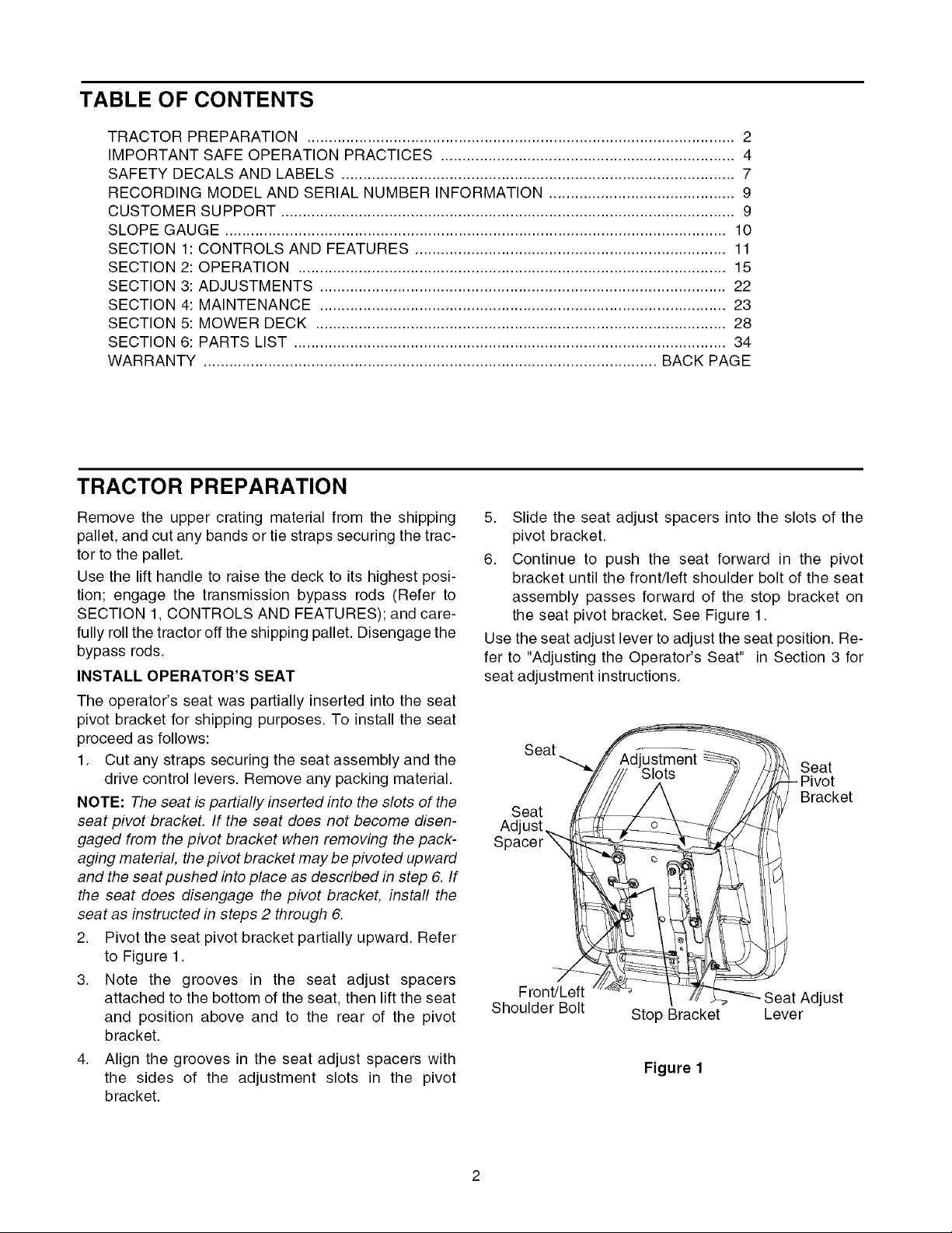
TABLE OF CONTENTS
TRACTOR PREPARATION ................................................................................................... 2
IMPORTANT SAFE OPERATION PRACTICES .................................................................... 4
SAFETY DECALS AND LABELS ........................................................................................... 7
RECORDING MODEL AND SERIAL NUMBER INFORMATION ........................................... 9
CUSTOMER SUPPORT ......................................................................................................... 9
SLOPE GAUGE .................................................................................................................... 10
SECTION 1: CONTROLS AND FEATURES ........................................................................ 11
SECTION 2: OPERATION ................................................................................................... 15
SECTION 3: ADJUSTMENTS .............................................................................................. 22
SECTION 4: MAINTENANCE .............................................................................................. 23
SECTION 5: MOWER DECK ............................................................................................... 28
SECTION 6: PARTS LIST .................................................................................................... 34
WARRANTY ......................................................................................................... BACK PAGE
TRACTOR PREPARATION
Remove the upper crating material from the shipping
pallet, and cut any bands or tie straps securing the trac-
tor to the pallet.
Use the lift handle to raise the deck to its highest posi-
tion; engage the transmission bypass rods (Refer to
SECTION 1, CONTROLS AND FEATURES); and care-
fully roll the tractor off the shipping pallet. Disengage the
bypass rods.
INSTALL OPERATOR'S SEAT
The operator's seat was partially inserted into the seat
pivot bracket for shipping purposes. To install the seat
proceed as follows:
1. Cut any straps securing the seat assembly and the
drive control levers. Remove any packing material.
NOTE: The seat is partially inserted into the slots of the
seat pivot bracket. If the seat does not become disen-
gaged from the pivot bracket when removing the pack-
aging material, the pivot bracket may be pivoted up ward
and the seat pushed into place as described in step 6. If
the seat does disengage the pivot bracket, install the
seat as instructed in steps 2 through 6.
2. Pivot the seat pivot bracket partially upward. Refer
to Figure 1.
3. Note the grooves in the seat adjust spacers
attached to the bottom of the seat, then lift the seat
and position above and to the rear of the pivot
bracket.
4. Align the grooves in the seat adjust spacers with
the sides of the adjustment slots in the pivot
bracket.
5. Slide the seat adjust spacers into the slots of the
pivot bracket.
6. Continue to push the seat forward in the pivot
bracket until the front/left shoulder bolt of the seat
assembly passes forward of the stop bracket on
the seat pivot bracket. See Figure 1.
Use the seat adjust lever to adjust the seat position. Re-
fer to "Adjusting the Operator's Seat" in Section 3 for
seat adjustment instructions.
Seat __ ^ .
"X////'s, ts/ I
Seat ____, /_/j_/_ Bracket
Adjusts.._ fI_j:_l_j.z_ _
Spacer _ _/_
Front/Left ...._'_ 7/_ Seat Adjust
Shoulder Bolt Stop Bracket Lever
Figure 1
Page 3

POSITIONDRIVECONTROL LEVERS
The drive control levers are unfastened from their re-
spective pivot brackets and lowered for shipping pur-
poses. The control levers must be repositioned and
secured to the pivot bracket to operate the tractor. Re-
position the control levers as follows:
• Remove the nut knob, bell washer, and carriage
bolt from either of the two control lever pivot
brackets. Refer to Figure 2.
• Lift and swing that control lever upward until the
slotted hole in the lever bracket aligns with one of
the holes in the pivot bracket. Refer to Figure 2.
• From the inside, insert the carriage bolt into the
pivot bracket and through the control lever slot. See
Figure 2.
• Slide the bell washer onto the carriage bolt, then
thread the nut knob onto the bolt. Fully tighten the
knob to temporarily secure control lever (See Figure
2). Refer to "Adjusting the Drive Control Levers" in
Section 3 for instructions on final adjustment of the
levers.
Carriage Bolt
The tractor is shipped with an activated sealed battery,
with the positive battery cable factory connected. The
negative cable must be connected.
NOTE: Make sure the ignition switch is in the "OFF'po-
sition before attaching the battery cable.
1. Pull the protective cap off the negative terminal of
the battery, and remove the hex cap screw and nut
from the free end of the negative battery cable.
2. Connect the negative battery cable (heavy black)
to negative terminal (NEG) of the battery using the
hex cap screw and nut. Slide the black terminal
cover over the negative terminal of the battery.
MODEL RZT42 ONLY
Remove The Chute Stop
• Locate the chute stop on the right side of the
mower, between discharge chute and cutting deck.
• While holding the discharge chute up, rotate the
chute stop clockwise and remove.
• Discard the chute stop.
Lift control
lever upward
...... Bell Washer
Pivot
Bracket
Slotted
Hole
Figure 2
Note the relative position of the contol lever to the
pivot bracket, then repeat the previous steps to
reposition the other control lever in approximately
the same position.
CONNECT THE BATTERY
,_ WARNING: Battery posts, terminals and
related accessories contain lead and lead
compounds. Wash hands after handling.
Figure 3
MODEL RZT50 ONLY
Lower Deck Discharge Chute
,_ WARNING: Never operate the mower deck
Locate the cable tie holding the deck discharge chute in
the up position for shipping purposes. Cut the cable tie
and lower the discharge chute.
without the discharge chute installed and
in the down position.
Page 4

WARNING
• The engine exhaust, some of its constituents, and certain vehicle components contain or emit chemicals known
to the State of California to cause cancer, birth defects or other reproductive harm.
• This unit is equipped with an internal combustion engine and should not be used on or near any unimproved
forest-covered, brush-covered, or grass-covered land unless the engine's exhaust system is equipped with a
spark arrester meeting applicable local or state laws (if any). If a spark arrester is used, it should be maintained
in effective working order by the operator.
• In the State of California, the above is required by law (Section 4442 of the California Public Resources Code).
Other States may have similar laws. Federal laws apply to federal lands. A spark arrester muffler is available
at your nearest engine authorized service center.
IMPORTANT
THIS SYMBOL POINTS OUT IMPORTANT SAFETY INSTRUCTIONS WHICH, IF NOT FOLLOWED,
COULD ENDANGER THE PERSONAL SAFETY AND/OR PROPERTY OF YOURSELF AND
OTHERS. READ AND FOLLOW ALL INSTRUCTIONS IN THIS MANUAL BEFORE ATTEMPTING
TO OPERATE YOUR UNIT. FAILURE TO COMPLY WITH THESE INSTRUCTIONS MAY RESULT
IN PERSONAL INJURY. WHEN YOU SEE THIS SYMBOL-- _IL HEED ITS WARNING.
Your lawn mower was built to be operated according to the rules for safe operation
in this manual. As with any type of power equipment, carelessness or error on the
DANGER
,_ I. GENERAL OPERATION
1. Read, understand and follow all instructions in the
manual and on the machine before starting. Keep
this manual in a safe place for future and regular
reference.
2. Only allow responsible individuals familiar with
the instructions to operate the machine. Know the
controls and how to stop the machine quickly.
3. Do not put hands or feet under the cutting deck or
near rotating parts.
4.
Clear the area of objects such as rocks, toys,
wire, etc. which could be picked up and thrown by
the blades. A small object may have been
overlooked and could be accidentally thrown by
the mower in any direction and cause injury to
you or a bystander. To help avoid a thrown
objects injury, keep children, animals, bystanders
and helpers at least 75 feet from the mower while
it is in operation. Always wear safety glasses with
side shields or safety goggles during operation or
while performing an adjustment or repair, to
protect eyes from foreign objects. Stop the blades
when crossing gravel drives, walks or roads.
part of the operator can result in injury. This lawn mower is capable of amputating
hands and feet or throwing objects. Failure to observe the following safety
instructions could result in serious injury or death.
SAFE OPERATION PRACTICES
5. Be sure the area is clear of other people before
mowing. Stop machine if anyone enters the area.
6. Never carry passengers.
7. Disengage the blades before shifting into reverse
and backing up. Always look down and behind
before and while backing.
8. Be aware of the mower and attachment discharge
direction and do not point it at anyone. Do not
operate the mower without either the entire grass
catcher or the chute guard in place.
9. Slow down before turning. Operate the machine
smoothly. Avoid erratic operation and excessive
speed.
10. Never leave a running machine unattended.
Always turn off the blades, place the transmission
in neutral, set the parking brake, stop the engine
and remove key before dismounting.
11.
Turn off blades when not mowing.
12.
Stop the engine and wait until the blades come to
a complete stop before (a) removing the grass
catcher or unclogging chute, or (b) making any
repairs, adjusting or removing any grass or debris.
Page 5
13.Mowonlyindaylightorgoodartificiallight.
14.Do not operatethe machinewhileunderthe
influenceofalcoholordrugs.
15.Watchfortrafficwhenoperatingnearorcrossing
roadways.
16.Useextracarewhenloadingor unloadingthe
machineintoatrailerortruck.Thisunitshouldnot
bedrivenupordowna rampontoatrailerortruck
underpower,becausethe unit couldtip over
causingseriouspersonalinjury.Theunitmustbe
pushedmanuallyona rampto loador unload
properly.
17.Nevermakea cuttingheightadjustmentwhilethe
engineisrunningiftheoperatormustdismountto
doso.
18.Wearsturdy,rough-soledworkshoesandclose-
fittingslacksandshirts.Donotwearloosefitting
clothesorjewelry.Theycanbecaughtinmoving
parts.Neveroperatea unitinbarefeet,sandals
or sneakers.
19.Checkoverheadclearancecarefullybeforedriving
underpowerlines,wires,bridgesorlowhanging
tree branches,before entering or leaving
buildings,or in any other situationwherethe
operatormaybe struckor pulledfromthe unit,
whichcouldresultinseriousinjury.
20.Disengageall attachmentclutches,set the
parkingbrakeintheonposition,andputthelap
bars to the neutralor out position before
attemptingtostarttheengine.
21.Yourmowerisdesignedtocutnormalresidential
grassof a heightno morethan 10". Do not
attemptto mowthroughunusuallytall,drygrass
(e.g.pasture)or pilesofdryleaves.Debrismay
builduponthemowerdeckorcontacttheengine
exhaustpresentingapotentialfirehazard.
22.Useonlyaccessoriesapprovedforthismachine
by Troy-Bilt.Read,understandandfollowall
instructions provided with the approved
accessory.
i_11. SLOPE OPERATION
Slopes are a major factor related to loss of control and
tip-over accidents, which can result in severe injury or
death. All slopes require extra caution. If you cannot
back up the slope or if you feel uneasy on it, do not
mow it.
For your safety, use the slope gauge included as part
of this manual to measure slopes before operating this
unit on a sloped or hilly area. Ifthe slope is greater than
15° as shown on the slope gauge, do not operate this
unit on that area or serious injury could result.
DO:
Mow across slopes, not up and down.
Remove obstacles such as rocks, limbs, etc.
Watch for holes, ruts or bumps. Uneven terrain could
overturn the machine. Tall grass can hide obstacles.
Use slow speed. Choose a low enough speed so that
you will not have to stop while on the slope.
Follow the manufacturer's recommendations for coun-
terweights with attachments to improve stability.
Use extra care with grass catchers or other attach-
ments. These can change the stability of the machine.
Keep all movement on the slopes slow and gradual.
Do not make sudden changes in speed or direction.
Rapid acceleration or deceleration could cause the
front of the machine to lift and rapidly flip over back-
wards, which could cause serious injury.
Avoid starting or stopping on a slope. If the tires lose
traction, disengage the blades and proceed slowly
straight down the slope.
DO NOT:
Do not turn on slopes unless necessary; if mowing
slopes, turn slowly and gradually uphill, if possible.
Do not mow near drop-offs, ditches or embankments.
The mower could suddenly turn over if a wheel is over
the edge of a cliff or ditch, or if an edge caves in.
Do not mow on wet grass. Reduced traction could
cause sliding.
Do not try to stabilize the machine by putting your foot
on the ground.
Do not use the grass catcher on steep slopes.
_k, III. CHILDREN
Tragic accidents can occur if the operator is not alert
to the presence of children. Children are often
attracted to the machine and the mowing activity.
Never assume that children will remain where you
last saw them.
1. Keep children out of the mowing area and in
watchful care of an adult other than the operator.
2. Be alert and turn the machine off if children enter
the area.
3. Before and when backing up, look behind and
down for small children.
4. Never carry children, even with the blades off.
They may fall off and be seriously injured or may
interfere with safe machine operation.
Page 6
5. Neverallow childrenunder 14 years old to
operatethemachine.Children14yearsandover
shouldonly operatethe machineunderclose
parentalsupervisionandproperinstruction.
6. Useextracarewhenapproachingblindcorners,
shrubs,treesorotherobjectsthatmayobscure
yourvisionof a childorotherhazard.
7. Removethe key when the machineis left
unattendedtopreventunauthorizedoperation.
,_ IV. SERVICE
1. Use extreme care in handling gasoline and other
fuels. They are extremely flammable and the
vapors are explosive.
a. Use only an approved container.
b. Never remove fuel cap or add fuel with the en-
gine running. Allow the engine to cool at least
two minutes before refueling.
c. Replace the fuel cap securely and wipe off any
spilled fuel before starting the engine as it may
cause a fire or explosion.
d. Extinguish all cigarettes, cigars, pipes and oth-
er sources of ignition.
e. Never refuel the machine indoors because fuel
vapors will accumulate in the area.
f. Never store the fuel container or machine
inside where there is an open flame or spark,
such as a gas hot water heater, space heater
or furnace.
2. Never run a machine inside a closed area.
3. To reduce fire hazard, keep the machine free of
grass, leaves or other debris build-up. Clean up
oil or fuel spillage. Allow the machine to cool at
least 5 minutes before storing.
4. Before cleaning, repairing or inspecting, make
certain the blade and all moving parts have
stopped. Disconnect the spark plug wire, and
keep the wire away from the spark plug to prevent
accidental starting.
5. Check the blade and engine mounting bolts at fre-
quent intervals for proper tightness. Also visually
inspect blades for damage (e.g., excessive wear,
bent, cracked). Replace with blades which meet
original equipment specifications.
6. Keep all nuts, bolts and screws tight to be sure
the equipment is in safe working condition.
7. Never tamper with safety devices. Check their
proper operation regularly. Use all guards as
instructed in this manual.
8. After striking a foreign object, stop the engine,
remove the wire from the spark plug and
thoroughly inspect the mower for any damage.
Repair the damage before restarting and
operating the mower.
9. Grass catcher components are subject to wear,
damage and deterioration, which could expose
moving parts or allow objects to be thrown. For
your safety protection, frequently check the
components and replace with manufacturer's
recommended parts when necessary.
10. Mower blades are sharp and can cut. Wrap the
blades or wear gloves, and use extra caution
when servicing blades.
11. Check the park brake operation frequently. Adjust
and service as required.
12. Muffler, engine and belt guards become hot
during operation and can cause a burn. Allow to
cool down before touching.
13. Do not change the engine governor settings or
overspeed the engine. Excessive engine speeds
are dangerous.
14. Observe proper disposal laws and regulations.
Improper disposal of fluids and materials can
harm the environment and the ecology.
a. Prior to disposal, contact your local
Environmental Protection Agency to
determine the proper method for disposing of
the waste. Recycling centers are established
to properly dispose of materials in an
environmentally safe fashion.
b. Use proper containers when draining fluids.
Do not use food or beverage containers that
may mislead someone into drinking from
them. Properly dispose of the containers im-
mediately following the draining of fluids.
C.
DO NOT pour oil or other fluids into the
ground, down a drain or into a stream, pond,
lake, or other body of water. Observe Environ-
mental Protection Agency regulations when
disposing of oil, fuel, coolant, brake fluid, fil-
ters, batteries, tires and other harmful waste.
15. We do not recommend the use of a pressure
washer or garden hose to clean your unit. They
may cause damage to electrical components;
spindles; pulleys; bearings; or the engine. The
use of water will result in shortened life and
reduce serviceability.
,_ WARNING - YOUR RESPONSIBILITY: Restrict the use of this power machine to persons who
read, understand and follow the warnings and instructions in this manual and on the machine.
Page 7
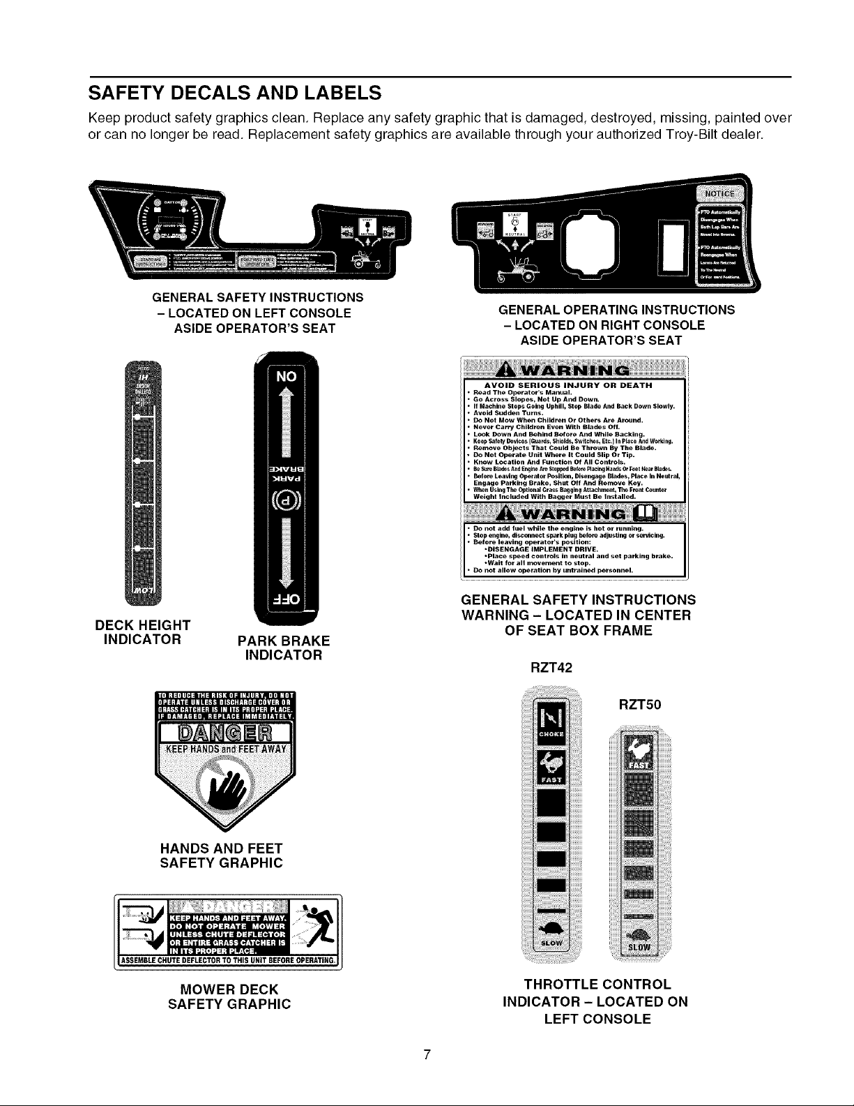
SAFETY DECALS AND LABELS
Keep product safety graphics clean. Replace any safety graphic that is damaged, destroyed, missing, painted over
or can no longer be read. Replacement safety graphics are available through your authorized Troy-Bilt dealer.
GENERAL SAFETY INSTRUCTIONS
- LOCATED ON LEFT CONSOLE
ASIDE OPERATOR'S SEAT
DECK HEIGHT
INDICATOR
PARK BRAKE
INDICATOR
GENERAL OPERATING INSTRUCTIONS
- LOCATED ON RIGHT CONSOLE
ASIDE OPERATOR'S SEAT
AVOID SERIOUS INJURY OR DEATH
Read The Operator's Manual.
Go Across Slopes, Not Up And Down.
If Machine Stops Going Uphill, Stop Blade And Back Down Slowly.
Avoid Sudden Turns.
Do Not Mow When Children Or Others Are Around.
Never Carry Children Even With Blades Off.
Look Down And Behind Before And While Backing.
Keep Safety Devices (Guarde_ Shields_ Switch_s_ Etc.) In Place And W0_king.
Remove Objects That Could Be Thrown By The Blade.
Do Not Operate Unit Where It Could Slip Or Tip.
Know Location And Function Of All Controls.
Be Sure Blades And Engin_ Are StopPed Before Placing Hands Or Lceet Near Blades,
Before Leaving Operator Position, Disengage Blades, Place In Neutral,
Engage Parking Brake, Shut Off And Remove Key.
When Using The OptionaJ Grass Bagging Attachment, The Front Counter
Weight Included With Bagger Must Be Installed.
Stop engine, disconnect spark plug before adjusting or servicing.
Before leaving operator's position:
"DISENGAGE IMPLEMENT DRIVE.
• Place speed controls in neutral and set parking brake.
.'Do not add fuel while the engine is hot or running.
• Wait for all movement to stop.
DO not allow operation by untrained personnel.
GENERAL SAFETY INSTRUCTIONS
WARNING - LOCATED IN CENTER
OF SEAT BOX FRAME
RZT42
HANDS ANDFEET
SAFETY GRAPHIC
_SSEMDLECHUTE DEFLECTORTO THISUNIT BEFOREOPERATING
MOWER DECK
SAFETY GRAPHIC
RZT50
THROTTLE CONTROL
INDICATOR- LOCATED ON
LEFT CONSOLE
Page 8

SAFETY DECALS AND LABELS
RZT42
RZT50
SAFETY GRAPHIC - LOCATED ON
LEFT SIDE OF MOWER DECK
INFORMATION GRAPHIC - BELT
ROUTING LOCATED ON
LEFT SIDE OF MOWER DECK
Page 9

RECORDING MODEL AND SERIAL NUMBER
This Operator's Manual is an important part of your new lawn tractor. It will help you assemble, prepare and
maintain the unit for best performance. Please read and understand what it says.
Before you start assembling your new equipment, please locate the model plate under the seat of the
tractor and copy the information in the space provided below. A sample model plate is also given below.
This information will be necessary to use the manufacturer's web site and/or help from the Customer Sup-
port Department or an authorized service dealer
Copy the model number here:
www.troybHt.com CLEVELAND_OH44136
P. O. BOX 361131
330-558-7220
866-840-6483
CUSTOMER SUPPORT
PleasedoNOTreturntheunit totheretailer fromwhere it waspurchased, without firstcontacting
CustomerSupport.
If you have difficulty assembling this product or have any questions regarding the controls, operation or
maintenance of this unit, you can seek help from the experts. Choose from the options below:
1. Visit troybilt.com. Click on Customer Service at the bottom of the page.
2. To reach the Customer Support Line, please call 1-866-840-6483 or 1-330-558-7220.
3. The engine manufacturer is responsible for all engine-related issues with regards to performance, power-
rating, specifications, warranty and service. Please refer to the engine manufacturer's Owner's/Operator's
Manual for more information.
Copy the serial number here:
Page 10

USE THIS PAGE AS A GUIDE TO DETERMINE SLOPES WHERE YOU MAY NOT OPERATE SAFELY.
i<1
I
SIGHT AND HOLD THIS LEVEL WITH A VERTICAL TREE
A POWER POLE
I
15 °
,_ WARNING
Do not mow on inclines with a slope in excess of 15 degrees (a rise of approximately 2-1/2 feet every 10 feet).
A riding mower could overturn and cause serious injury. If operating a walk-behind mower on such a slope, it is
extremely difficult to maintain your footing and you could slip, resulting in serious injury.
Operate RZT zero turn tractors across the face of slopes rather than up and down. Begin with the first pass
across the bottom of the slope and turn uphill at the end of each pass whenever possible.
Page 11
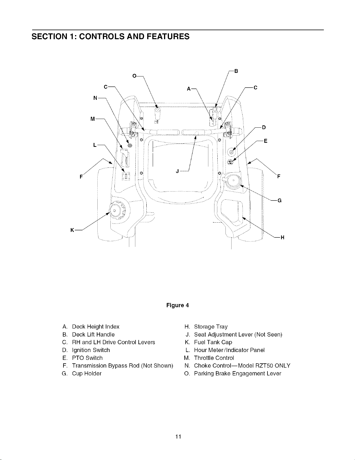
SECTION 1" CONTROLS AND FEATURES
\\ \ \ _ i/
K ¸
A, Deck Height Index
B, Deck Lift Handle
C, RH and LH Drive Control Levers
D, Ignition Switch
E. PTO Switch
F. Transmission Bypass Rod (Not Shown)
G, Cup Holder
/
\
Figure 4
H, Storage Tray
J. Seat Adjustment Lever (Not Seen)
K. Fuel Tank Cap
L. Hour Meter/Indicator Panel
M. Throttle Control
N. Choke Control--Model RZT50 ONLY
O, Parking Brake Engagement Lever
11
Page 12
NOTE:References to LEFT, RIGHT, FRONT, and
REAR indicate that position on the tractor when
facing forward while seated in the operator's seat.
A. Deck Height Index
The deck height index consists of six index notches
located on the front/right of the seat box frame. Each
notch corresponds to a 1/2 inch change in the deck
height position ranging from 1-1/2 inches at the low-
est notch to 4 inches at the highest notch.
B. Deck Lift Handle
The deck lift handle is located on the front/right of the
seat box frame, and is used to raise and lower the
mower deck.
Pull the handle to the left out of the index notch and
push downward to lower the deck, or pull upward to
raise the deck. When the desired height is attained,
move the lift handle to the right until fully in the index
notch.
C. RH and LH Drive Control Levers
The RH and LH control levers are located to each
side of the operator's seat. These hinged levers open
out to the side in the neutral position to permit the
operator to be seated or to leave the tractor seat. The
levers must be fully opened out in the neutral position
to start the tractor engine.
Each lever controls the respective RH or LH transmis-
sion. Consequently, these levers control all of the
movements of the tractor. Driving and steering utiliz-
ing these control levers is quite different from
conventional tractors, and will take some practice to
master. Refer to SECTION 2: OPERATION for
instructions on using the control levers.
D. Ignition Switch
The ignition switch is located on the RH console to
the right of the operator's seat.
The ignition switch has three positions as follow:
NOTE: To prevent accidental starting and/or battery
discharge, remove the key from the ignition switch
when the tractor is not in use.
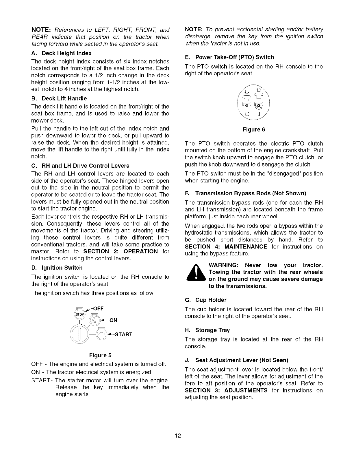
E. Power Take-Off (PTO) Switch
The PTO switch is located on the RH console to the
right of the operator's seat.
Figure 6
The PTO switch operates the electric PTO clutch
mounted on the bottom of the engine crankshaft. Pull
the switch knob upward to engage the PTO clutch, or
push the knob downward to disengage the clutch.
The PTO switch must be in the "disengaged" position
when starting the engine.
F. Transmission Bypass Rods (Not Shown)
The transmission bypass rods (one for each the RH
and LH transmission) are located beneath the frame
platform, just inside each rear wheel.
When engaged, the two rods open a bypass within the
hydrostatic transmissions, which allows the tractor to
be pushed short distances by hand. Refer to
SECTION 4: MAINTENANCE for instructions on
using the bypass feature.
,_WARNING: Never tow your tractor.
G. Cup Holder
The cup holder is located toward the rear of the RH
console to the right of the operator's seat.
Towing the tractor with the rear wheels
on the ground may cause severe damage
to the transmissions.
Figure 5
OFF - The engine and electrical system is turned off.
ON - The tractor electrical system is energized.
START- The starter motor will turn over the engine.
Release the key immediately when the
engine starts
H. Storage Tray
The storage tray is located at the rear of the RH
console.
J. Seat Adjustment Lever (Not Seen)
The seat adjustment lever is located below the front/
left of the seat. The lever allows for adjustment of the
fore to aft position of the operator's seat. Refer to
SECTION 3: ADJUSTMENTS for instructions on
adjusting the seat position.
12
Page 13
K. FuelTankCap
Thefueltankcap is locatedat the rearof theLH
console.Turnthecapcounterclockwisetounscrew
andremovefromthefueltank.Alwaysre-installthe
fuelcaptightlyontothefueltankafterremoving.
WARNING: Never fill the fuel tank when
the engine is running. If the engine is hot
from recently running, allow to cool for
several minutes before refueling. Highly
flammable gasoline could splash onto
the engine and cause a fire.
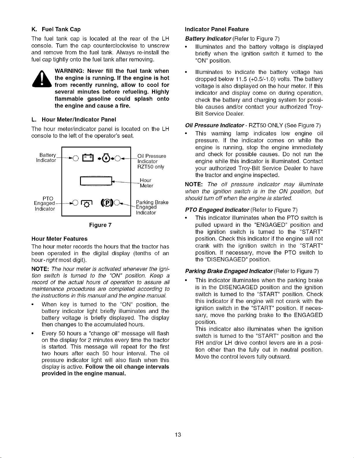
L. Hour Meter/Indicator Panel
The hour meter/indicator panel is located on the LH
console to the left of the operator's seat.
Battery_
Indicator
PTO
Engaged--
Indicator
Hour Meter Features
The hour meter records the hours that the tractor has
been operated in the digital display (tenths of an
hour- right most digit).
NOTE: The hour meter is activated whenever the igni-
tion switch is turned to the "ON" position. Keep a
record of the actual hours of operation to assure all
maintenance procedures are completed according to
the instructions in this manual and the engine manual
• When key is turned to the "ON" position, the
battery indicator light briefly illuminates and the
battery voltage is briefly displayed. The display
then changes to the accumulated hours.
• Every 50 hours a "change oil" message will flash
on the display for 2 minutes every time the tractor
is started. This message will repeat for the first
two hours after each 50 hour interval. The oil
pressure indicator light will also flash when this
display is active. Follow the oil change intervals
provided in the engine manual.
-,-0 D
Figure 7
Oil Pressure
--Indicator
RZT50 only
Hour
--Meter
Parking Brake
_Engaged
Indicator
Indicator Panel Feature
Battery Indicator (Refer to Figure 7)
• Illuminates and the battery voltage is displayed
briefly when the ignition switch it turned to the
"ON" position.
Illuminates to indicate the battery voltage has
dropped below 11.5 (+0.5/-1.0) volts. The battery
voltage is also displayed on the hour meter. If this
indicator and display come on during operation,
check the battery and charging system for possi-
ble causes and/or contact your authorized Troy-
Bilt Service Dealer.
Oil Pressure Indicator - RZT50 ONLY (See Figure 7)
• This warning lamp indicates low engine oil
pressure. If the indicator comes on while the
engine is running, stop the engine immediately
and check for possible causes. Do not run the
engine while this indicator is illuminated. Contact
your authorized Troy-Bilt Service Dealer to have
the tractor and engine inspected.
NOTE: The oil pressure indicator may illuminate
when the ignition switch is in the ON position, but
should turn off when the engine is started.
PTO Engaged Indicator (Refer to Figure 7)
• This indicator illuminates when the PTO switch is
pulled upward in the "ENGAGED" position and
the ignition switch is turned to the "START"
position. Check this indicator if the engine will not
crank with the ignition switch in the "START"
position. If necessary, move the PTO switch to
the "DISENGAGED" position.
Parking Brake Engaged Indicator (Refer to Figure 7)
• This indicator illuminates when the parking brake
is in the DISENGAGED position and the ignition
switch is turned to the "START" position. Check
this indicator if the engine will not crank with the
ignition switch in the "START" position. If neces-
sary, move the parking brake to the ENGAGED
position.
This indicator also illuminates when the ignition
switch is turned to the "START" position and the
RH and/or LH drive control levers are in a posi-
tion other than the fully out in neutral position.
Move the control levers fully outward.
13
Page 14
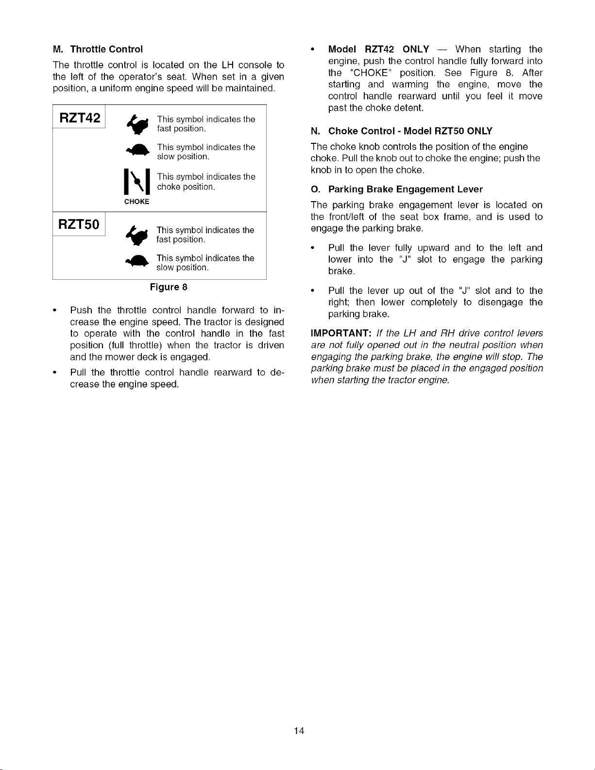
M. ThrottleControl
ThethrottlecontrolislocatedontheLHconsoleto
theleftof theoperator'sseat.Whensetin a given
position,auniformenginespeedwillbemaintained.
Model RZT42 ONLY -- When starting the
engine, push the control handle fully forward into
the "CHOKE" position. See Figure 8. After
starting and warming the engine, move the
control handle rearward until you feel it move
past the choke detent.
RZT42 J fastThiSposition.Symb°lindicates the
This symbol indicates the
slow position.
Ik I This symbo, indicates the
CHOKE
choke position.
RZT501
This symbol indicates the
fast position.
This symbol indicates the
slow position.
Figure 8
• Push the throttle control handle forward to in-
crease the engine speed. The tractor is designed
to operate with the control handle in the fast
position (full throttle) when the tractor is driven
and the mower deck is engaged.
• Pull the throttle control handle rearward to de-
crease the engine speed.
N. Choke Control - Model RZT50 ONLY
The choke knob controls the position of the engine
choke. Pull the knob out to choke the engine; push the
knob in to open the choke.
O. Parking Brake Engagement Lever
The parking brake engagement lever is located on
the front/left of the seat box frame, and is used to
engage the parking brake.
• Pull the lever fully upward and to the left and
lower into the "J" slot to engage the parking
brake.
• Pull the lever up out of the "J" slot and to the
right; then lower completely to disengage the
parking brake.
IMPORTANT: If the LH and RH drive control levers
are not fully opened out in the neutral position when
engaging the parking brake, the engine will stop. The
parking brake must be placed in the engaged position
when starting the tractor engine.
14
Page 15
SECTION 2: OPERATION
GENERAL SAFETY
• RECEIVE INSTRUCTION - Read the operator's
manual. Learn to operate this machine SAFELY.
Don't risk INJURY or DEATH. Allow only those
who have become competent in its usage to
operate this tractor.
• Familiarize yourself with the operations of all the
instruments and controls.
• Before starting the engine or beginning operation,
be familiar with the controls. The operator should
be in the operator's seat. The PTO switch must
be in the disengaged position, the parking brake
engaged, and the RH and LH drive control levers
moved fully outward in the neutral position.
• Keep all shields in place. Keep away from moving
parts.
• NO RIDERS! Keep all people and pets a safe
distance away. Look behind and down to both
sides of the tractor before and while backing up.
• DO NOT direct the mower discharge at people.
• Avoid slopes where possible. Never operate on
slopes greater than 15°. Slopes with a greater
incline present dangerous operating conditions.
Tractors can be rolled over.
• Before leaving the operator's seat: Shut off the
PTO, move the RH and LH drive control levers
fully outward in the neutral position, engage the
parking brake, shut off the engine and remove
the ignition key. Wait for all movement to stop
before servicing or cleaning.
• Operate the drive control levers smoothly and
avoid any sudden movements of the levers
when starting and stopping. Keep a firm grip on
the control levers; do not allow the levers to
return to neutral on their own.
• Be careful when operating near roadways. Stop
the tractor motion and wait for vehicles to pass
before operating along the road.
• Do not operate the tractor with the mower deck
removed. Removal of the deck will change the
balance of the tractor, and could contribute to a
tractor rollover.
• Avoid operation on traction surfaces that are
unstable; use extreme caution if the surface is
slippery.
• Slow down before turning and come to a
complete stop before any zero turn maneuver.
• Do not stop the tractor or park the tractor over
combustible materials such as dry grass, leaves,
debris, etc.
• Do not fill the fuel tank when the engine is
running or while the engine is hot. Allow the
engine several minutes to cool before refueling.
Tighten the fuel cap securely.
BEFORE OPERATING YOUR TRACTOR
• Before you operate the tractor, study this manual
and the engine manual carefully. They have been
prepared to help you operate and maintain your
tractor efficiently.
• Familiarize yourself with the operations of all the
instruments and controls.
• This engine is certified to operate on unleaded
gasoline. For best results, fill the fuel tank with
only clean, fresh, unleaded gasoline with a pump
sticker octane rating of 85 or higher. Unleaded
gasoline is recommended because it leaves less
combustion chamber deposits.
Some fuels are gasoline blended with alcohols or
ethers. Excessive amounts of the these blends
can damage the fuel system or cause engine
performance problems. If undesirable operating
symptoms occur, use gasoline with a lower
percentage of alcohol or ether. Do not use
gasoline that contains Methanol.
• Check the engine oil level. See Engine Manual.
IMPORTANT: Your tractor is shipped with motor
oil in the engine. However, you MUST check the
oil level before operating. The capacity of the
engine is approximately 48 oz. (1.4 liters) for the
model RZT42 and 64 oz. (1.9 liters), for the
model RZT50 (with oil filter). Do not to overfill.
• Clean the air cleaner element if necessary. See
Engine Manual.
• Check the tire inflation pressures.
• Adjust the seat for operator's maximum comfort,
visibility, and for maintaining complete control of
the tractor.
SAFETY INTERLOCK SYSTEM
This tractor is equipped with a safety interlock system
for the protection of the operator. If the interlock system
should ever malfunction, do not operate the tractor.
Contact your authorized Troy-Bilt Service Dealer.
• The safety interlock system prevents the engine
from cranking or starting unless the RH and LH
drive control levers are moved fully outward in the
neutral position, the parking brake is engaged,
and the PTO is disengaged.
• To avoid sudden movement when disengaging
the parking brake, the safety interlock system will
shut off the engine if the RH and/or LH drive
control levers are moved to a position other than
the fully out in neutral position when the parking
brake is engaged
• The safety interlock system will shut off the
engine if the operator leaves the seat before
engaging the parking brake.
15
Page 16

• The safetyinterlocksystemwill shut off the
engineif the operatorleavesthe seatwiththe
PTOengaged,regardlessofwhethertheparking
brakeisengaged.
NOTE:The PTO switch must be moved to the
"OFF" position to restart the engine.
• The safety interlock system will shut off the PTO
and the mower blades will stop if both drive con-
trol levers are moved into the reverse position.
The PTO will re-engage when one or both of the
levers are moved back to the neutral or forward
position.
STARTING THE ENGINE
WARNING: For personal safety, the
operator must be sitting in the tractor
seat when starting the engine.
WARNING: This unit is equipped with a
safety interlock system designed for the
protection of the operator. Do not oper-
ate the tractor if any part of the interlock
system is malfunctioning. Periodically
check the functions of the interlock sys-
tem for proper operation.
Move the RH and LH drive control levers fully
outward in the neutral position. Refer to Figure 9.
Operator must be sitting in the tractor seat.
Engage the parking brake. Refer to Figure 9.
Make certain the PTO switch is in the disen-
gaged (down) position. Refer to Figure 9.
Model RZT42 ONLY
1. Move the throttle control lever fully forward
into the "CHOKE" position. NOTE: If the
engine is warmed up, it may not be necessary
to place the throttle control in the choke
position.
2. Turn the ignition key clockwise to the "START"
position and release it as soon as the engine
starts; however, do not crank the engine
continuously for more than 5 seconds at a
time. If the engine does not start within this
time, turn the key to "OFF" and wait a minute
to allow the engine's starter motor to cool. Try
again after waiting. If after a few attempts the
engine fails to start, do not keep trying to start
it with the choke closed as this will cause
flooding and make starting more difficult.
3. As the engine warms up, gradually pull the
throttle control lever rearward past the choke
detent position. Do not use the choke to enrich
the fuel mixture, except as necessary to start
the engine.
Model ZT50 ONLY
1. Pull the choke control knob upward to the full
choke position. NOTE: If the engine is warmed
up, it may not be necessary to choke the
engine.
2. Move the throttle control lever fully forward to
the "fast" position.
LH Control Lever
Out in Neutral
i
RZT42 - Move Throttle
Control to Choke
RZT50 - Move Throttle
Control to "FAST"
RH Control Lever
Out in Neutral
I
I
/
PTOSwitch in Down
(Disengaged) Position
Figure 9
3. Turn the ignition key clockwise to the "START"
position and release it as soon as the engine
starts; however, do not crank the engine
continuously for more than 5 seconds at a
time. If the engine does not start within this
time, turn the key to "OFF" and wait a minute
to allow the engine's starter motor to cool. Try
again after waiting. If after a few attempts the
engine fails to start, do not keep trying to start
it with the choke closed as this will cause
flooding and make starting more difficult.
4. As the engine warms up, gradually push the
choke knob downward to open the choke. Do
not use the choke to enrich the fuel mixture,
except as necessary to start the engine.
Allow the engine to warm up before putting the
engine under load.
Observe the hour meter/indicator panel. If the
battery indicator light or oil pressure light (RZT50
only) come on, immediately stop the engine.
Have the tractor inspected by your authorized
Troy-Bilt Service Dealer dealer.
16
Page 17

COLDWEATHERSTARTING
Be sureto use the properoil for the expected
temperatures(checkthetableintheenginemanual).
Followthenormalenginestartinginstructionsabove.
However,allowthe engineampletimeto warmup
beforeputtingthetractorunderload.
USINGJUMPERCABLESTOSTARTENGINE
_ WARNING:Batteries contain sulfuric acid
If the battery charge is not sufficient to crank the
engine, recharge the battery. If a battery charger is
unavailable and the tractor must be started, the aid of
a booster battery will be necessary. Connect the
booster battery as follows:
• Connect the end of one cable to the disabled
• Connect one end of the other cable to the booster
• Start the disabled tractor following the normal
• Have the tractor's electrical system checked and
STOPPING THE ENGINE
• Place the PTO switch in the "OFF" position.
• Move the RH and LH drive control levers fully
• Engage the parking brake.
• Model RZT42 ONLY -- Place the throttle control
• Model RZT50 ONLY -- Place the throttle control
and produce explosive gasses. Make
certain the area is well ventilated, wear
gloves and eye protection, and avoid
sparks or flames near the battery.
tractor battery's positive terminal; then connect
the other end of that cable to the booster
battery's positive terminal.
battery's negative terminal; then connect the
other end of that cable to the frame of the dis-
abled tractor, as far from the battery as possible.
starting instructions previously provided; then
disconnect the jumper cables in the exact reverse
order of their connection.
repaired as soon as possible to eliminate the
need for jump starting.
outward in the neutral position.
lever in the fast (high idle) position.
lever in the slow (idle) position.
• Turn the ignition key to the "OFF" position and
remove the key from the ignition switch.
NOTE: Always remove the key from the ignition
switch to prevent accidental starting or battery
discharge if the equipment is left unattended.
PRACTICE OPERATION (INITIAL USE)
Operating a zero-turn tractor is not like operating a
conventional type riding tractor. Although and be-
cause a zero-turn tractor is more maneuverable, get-
ting used to operating the control levers takes some
practice.
We strongly recommend that you locate a reason-
ably large, level and open "practice area" where there
are no obstructions, pedestrians, or animals. You
should practice operating the tractor for a minimum of
30 minutes.
Carefully move (or have moved) the tractor to the
practice area. When performing the practice session,
the PTO should not be engaged. While practicing,
operate the tractor at approximately 1/2-3/4 throttle
and at less than full speed in both forward and
reverse.
Carefully practice maneuvering the tractor using the
instructions in the following section "Driving the Trac-
tor." Practice until you are confident that you can
safely operate the tractor.
DRIVING THE TRACTOR
_ ARNING: Avoid sudden starts, exces-
• Release the parking brake.
sive speed and sudden stops.
WARNING: Do not leave the seat of the
tractor without disengaging the PTO,
moving drive control levers fully outward
in the neutral position, and engaging the
parking brake. If leaving the tractor
unattended, turn the ignition key off and
remove key.
Adjust the operator's seat to the most
comfortable position that allows you to operate
the controls. See seat adjustment in the
ADJUSTMENTS section.
17
Page 18

• Move the RH and LH drive control levers inward
in the neutral position. See Figure 10.
Control Lever Moved
Inward and in Neutral
o
Figure 10
NOTE: If the control levers are not even in the neutral
position, refer to Section 3 and adjust the levers so
that they are even.
• Move the throttle control lever forward to the full
throttle position (3500-3600 RPM).
NOTE: The tractor and engine are designed to run at
full throttle. If performing a practice session, it is
preferable that the tractor is operated at less than full
throttle (approximately 2500-3000 RPM), but this only
applies to practice operation.
NOTE: For Model RZT42, make certain the throttle
control has not been moved too far forward into the
"Choke" position.
• To drive the tractor, firmly grasp the respective
drive control levers with your right and left hands
and proceed as follows :
_ WARNING: Always maintain a firm grip
on the control levers. DO NOT release the
control levers to slow or stop the tractor;
move the levers to the neutral position
using your hands.
DRIVING FORWARD
Faster
Slower
Neutral
Position
Figure 11
• To slow the tractor move the controls lever
rearward to attain the desired speed, or move the
levers to the neutral position to stop the tractor.
IMPORTANT: Always maintain your grasp on the
drive control levers. Do not release the levers to
slow the tractor or to return to neutral.
Turning the Tractor While Driving Forward
_ WARNING: When reversing the direction
of travel, we recommend performing
gradual °U' turns where possible.
Sharper turns increase the possibility of
turf defacement, and could affect control
of the tractor. ALWAYS slow the tractor
before making sharp turns.
To turn the tractor while driving forward, move the
control levers as necessary so that one lever is
rearward of the other. The tractor will turn in the
direction of the rearward control lever.
- To turn to the left, move the left drive control
lever rearward of the right lever. See Figure 12.
FORWARD LEFT TURN
Driving the Tractor Forward
_ WARNING: Keep all movement of the
drive control levers slow and smooth.
Abrubt movement of the control levers
can affect the stability of the tractor and
could cause the tractor to flip over,
which may result in serious injury or
death to the operator.
• Slowly and evenly move both drive control levers
forward. The tractor will start to move forward.
See Figure 11.
• As the control levers are pushed farther forward
the speed of the tractor will increase.
Figure 12
18
Page 19
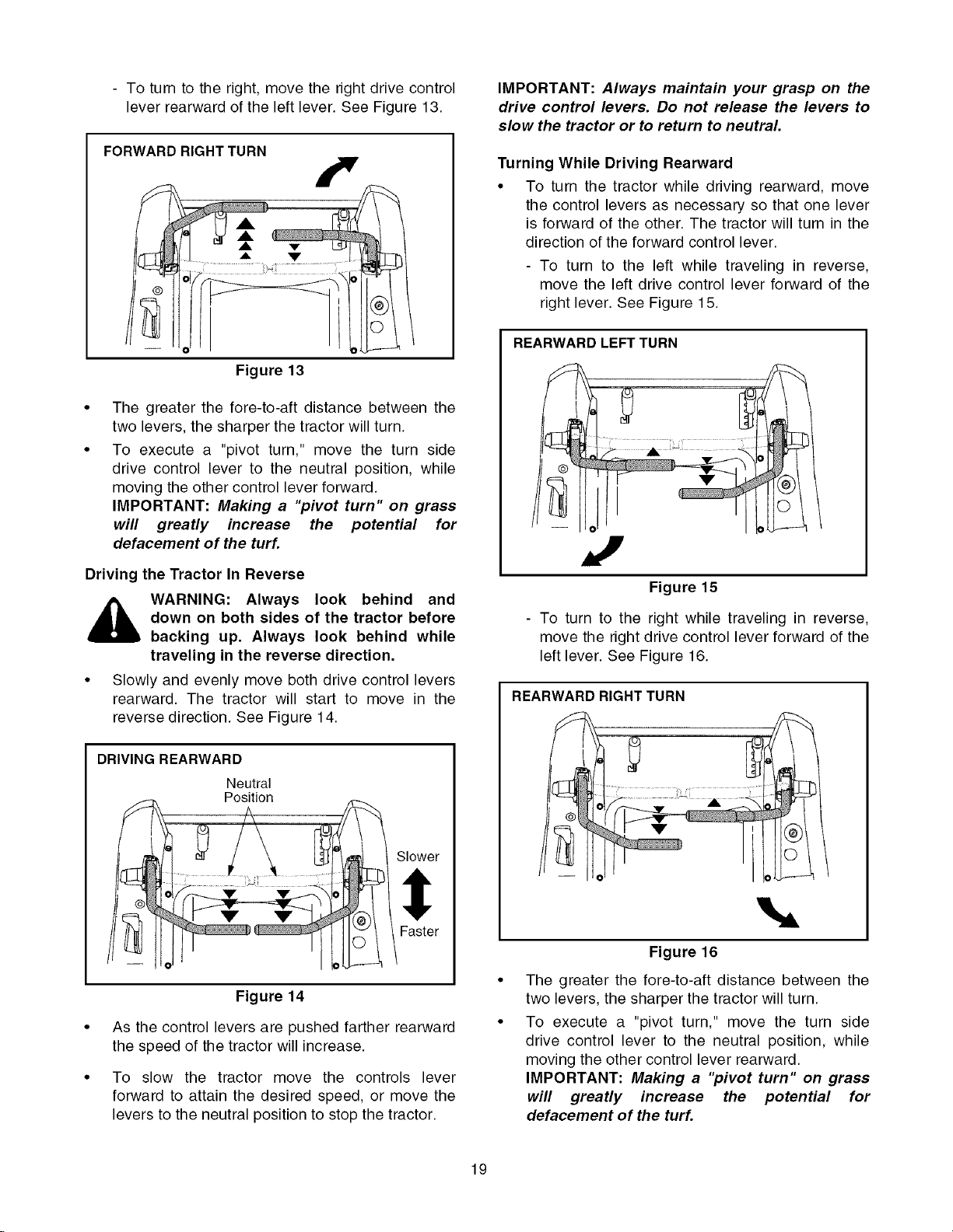
- Toturntotheright,movetherightdrivecontrol
leverrearwardoftheleftlever.SeeFigure13.
FORWARD RIGHT TURN
Figure 13
The greater the fore-to-aft distance between the
two levers, the sharper the tractor will turn.
To execute a "pivot turn," move the turn side
drive control lever to the neutral position, while
moving the other control lever forward.
IMPORTANT: Making a "pivot turn" on grass
will greatly increase the potential for
defacement of the turf.
IMPORTANT: Always maintain your grasp on the
drive control levers. Do not release the levers to
slow the tractor or to return to neutral.
Turning While Driving Rearward
• To turn the tractor while driving rearward, move
the control levers as necessary so that one lever
is forward of the other. The tractor will turn in the
direction of the forward control lever.
- To turn to the left while traveling in reverse,
move the left drive control lever forward of the
right lever. See Figure 15.
REARWARD LEFT TURN
Driving the Tractor In Reverse
_ WARNING: Always look behind and
down on both sides of the tractor before
backing up. Always look behind while
traveling in the reverse direction.
• Slowly and evenly move both drive control levers
rearward. The tractor will start to move in the
reverse direction. See Figure 14.
DRIVING REARWARD
Neutral
Position
Slower
Figure 14
As the control levers are pushed farther rearward
the speed of the tractor will increase.
To slow the tractor move the controls lever
forward to attain the desired speed, or move the
levers to the neutral position to stop the tractor.
Figure 15
- To turn to the right while traveling in reverse,
move the right drive control lever forward of the
left lever. See Figure 16.
REARWARD RIGHT TURN
!
Figure 16
The greater the fore-to-aft distance between the
two levers, the sharper the tractor will turn.
To execute a "pivot turn," move the turn side
drive control lever to the neutral position, while
moving the other control lever rearward.
IMPORTANT: Making a "pivot turn" on grass
will greatly increase the potential for
defacement of the turf.
19
Page 20

Executing a Zero Turn
,_ WARNING: When executing a zero turn,
the tractor MUST BE STOPPED.
Executing a zero turn while the tractor is
moving can significantly reduce your
control of the tractor and will cause
severe turf defacement to occur.
• Stop the forward or reverse motion of the tractor
by moving the two drive control levers to neutral.
• To turn clockwise, slowly move the left control
lever forward while simultaneously moving the
right control lever rearward. See Figure 17.
CLOCKWISE ZERO TURN
Figure 17
To turn counterclockwise, slowly move the right
control lever forward while simultaneously moving
the left control lever rearward. See Figure 18.
COUNTERCLOCKWISE ZERO TURN
Figure 18
STOPPING THE TRACTOR
• Move both drive control levers to the neutral
position to stop the motion of the tractor.
• Push the PTO switch downward to the
disengaged position.
• Use the deck lift handle to raise the deck to its
highest position.
• If dismounting the tractor:
- Move the drive control handles fully outward in
the neutral position.
- Engage the parking brake.
- Move the throttle control lever to the fast
position if operating a RZT42 tractor, or to the
slow position if operating a RZT50 tractor.
- Turn the ignition switch to "OFF'" and remove
the key from the switch.
DRIVING ON SLOPES
Refer to the SLOPE GAUGE on page 10 to help
determine slopes where you may not operate safely.
with a slope in excess of 15 degrees (a
WARNING: Do not operate on inclines
rise of approximately 2-1/2 feet every 10
feet). The tractor could overturn and
cause serious injury.
• Always drive across slopes, never up and down.
Control the speed and direction of the tractor
using primarily the control lever on the downhill
side of the tractor, with the uphill control lever
remaining essentially in a fixed position.
• Avoid turning downhill if possible. Start at the
bottom of a slope and work upward. Always slow
down before turning.
• Use extra care and go slowly when turning
downhill.
OPERATING THE PTO
Operate the PTO clutch as follows:
• Move the throttle control lever to approximately
the mid throttle position.
• Pull the PTO switch upward to the "ENGAGED"
position.
• Advance the throttle lever to the operating speed
(full engine speed).
• The operator must remain in the tractor seat at all
times. If the operator should leave the seat
without turning off the power take-off switch, the
tractor's engine will shut off.
• The PTO clutch cannot be operated when the
tractor is driving in the reverse direction. The
PTO will disengage when both drive control
levers are moved to the reverse position, and will
re-engage when one (or both) control levers are
moved to the neutral or forward position.
2O
Page 21

USING THE MOWER DECK
WARNING: Make certain the area to be
mowed is free of debris, sticks, stones,
wire or other objects that can be thrown
by the rotating blades.
IMPORTANT: Do not engage the mower deck
when lowered in grass. Premature wear and
possible failure of the 'V" belt and PTO clutch will
result. Fully raise the deck or move to a non
grassy area before engaging the mower deck.
• Mow across slopes, not up and down. If mowing
a slope, start at bottom and work upward to
ensure turns are made uphill.
• On the first pass pick a point on the opposite side
of the area to be mowed.
• Engage the PTO clutch using the PTO switch and
move the throttle control to the fast position.
• Lower the mower deck to the desired height
setting using the lift handle.
• Slowly and evenly push the RH and LH drive
control levers forward to move the tractor
forward, and keep the tractor headed directly
toward the alignment point.
NOTE: The speed of the tractor will affect the
quality of the mower cut. Mowing at full speed will
adversely affect the cut quality. Control the
ground speed with the control levers.
• When approaching the other end of the strip,
slow down or stop before turning. A U-turn is
recommended unless a pivot or zero turn is
required.
• Align the mower with an edge of the mowed strip
and overlap approximately 3 inches.
• Direct the tractor on each subsequent strip to
align with a previously cut strip.
• To prevent rutting or grooving of the turf, if
possible, change the direction that the strips are
mowed by approximately 45° for the next and
each subsequent mowing.
WARNING: Be careful when crossing
gravel paths or driveways. Disengage
the PTO and raise the deck to the
highest position before crossing.
IMPORTANT: When stopping the tractor for any
reason while on a grass surface, always:
• Place the shift lever in neutral,
• Engage the parking brake,
• Shut engine off and remove the key.
Doing so will minimize the possibility of having your
lawn "browned" by hot exhaust from your tractor's
running engine.
CHECKING THE SAFETY INTERLOCK CIRCUITS
Periodically check the safety interlock circuits to
ensure they are working properly. If a safety circuit is
not working as designed, contact you authorized
Troy-Bilt Service Dealer to have the tractor inspected.
DO NOT operate the tractor if any safety circuit is not
functioning properly. To check the safety circuits,
proceed as follows:
• Sitting in the tractor seat with both drive control
levers opened fully outward, disengage the
parking brake and momentarily turn the ignition
switch to the start position. The engine should not
crank.
• Engage the parking brake and pull the PTO
switch upward to the engaged position.
Momentarily turn the ignition switch to the start
position; the engine should not crank.
• Push the PTO switch downward to the disen-
gaged position and engage the parking brake.
Start the engine and move one of the drive con-
trol levers from the fully outward neutral position.
The engine should stop running. Repeat the pro-
cedure with the opposite control lever.
• Move both control levers fully outward in the neu-
tral position and disengage the parking brake;
then lift upward from the operator's seat. The
engine should stop.
• With both control levers fully outward in the neu-
tral position and the parking brake engaged,
engage the PTO. Lift upward from the operator's
seat; the engine should stop.
• Start the tractor, disengage the parking brake,
and move the control levers inward to the neutral
operating position. Engage the PTO and move
both control lever slowly into the slow reverse
position; the PTO should disengage and the
mower deck should stop until one or both of the
control levers are moved to the neutral or for-
ward position.
21
Page 22

SECTION 3: ADJUSTMENTS
ADJUSTING THE OPERATORS SEAT
• To adjust the position of the seat, move and hold
the seat adjustment lever toward the left. Slide
the seat forward or rearward to the desired
position; then release the adjustment lever. Make
sure seat is locked into position before operating
the tractor. See Figure 19.
Seat
\
Move Lever
_to Left
z- Lever
Adjustment
Figure 19
• Insert the carriage bolt through the pivot bracket
and control lever slot. Slide the bell washer onto
the bolt and screw on the nut knob, but do not
fully tighten now.
• If you are going to adjust the control levers
forward or rearward, proceed to the next step. If
not, fully tighten nut knob.
Carriage Bolt PivotBracket
\_--Control Lever
Hex Insert
Flare Knob
Lock Nut
Slot Shoulder
Hgt. Adjust Holes
Screw
Figure 20
ADJUSTING RH & LH DRIVE CONTROL LEVERS
The RH and LH drive control levers can be adjusted
up or down and fore-and-aft for the comfort of the
operator. The drive control levers can be placed in
either of two height positions, or can be moved
forward or rearward within the range of the slot in
each control lever mounting bracket.
To adjust the drive control lever height, proceed as
follows:
• Remove the nut knob, bell washer, and carriage
bolt securing the lever to the pivot bracket.
• While supporting the control lever to keep it from
falling, remove the hex insert flange lock nut and
shoulder screw from the bottom of the control
lever and pivot bracket. Refer to Figure 20.
• Reposition the control lever to align with the other
set of holes in the pivot bracket and insert the
shoulder screw removed earlier. Fasten with the
hex insert flange lock nut and tighten until snug.
To adjust the drive control levers forward or rearward,
proceed as follows:
Loosen the nut knob and rotate the control lever
either forward or rearward to the desired position.
See Figure 20.
NOTE: If the control lever is too tight to move, slightly
loosen the hex insert flange lock nut and shoulder
screw at the bottom of the control lever.
Tighten the nut knob to fix the control lever in the
adjusted position
Repeat the above procedure to adjust the other
control lever into the same position. Adjust so
that both levers are even with each other when in
the neutral position.
22
Page 23
SECTION 4: MAINTENANCE
ENGINE MAINTENANCE
Engine maintenance procedures and schedules
can be found in the engine manual. Follow those
instructions for performing engine maintenance.
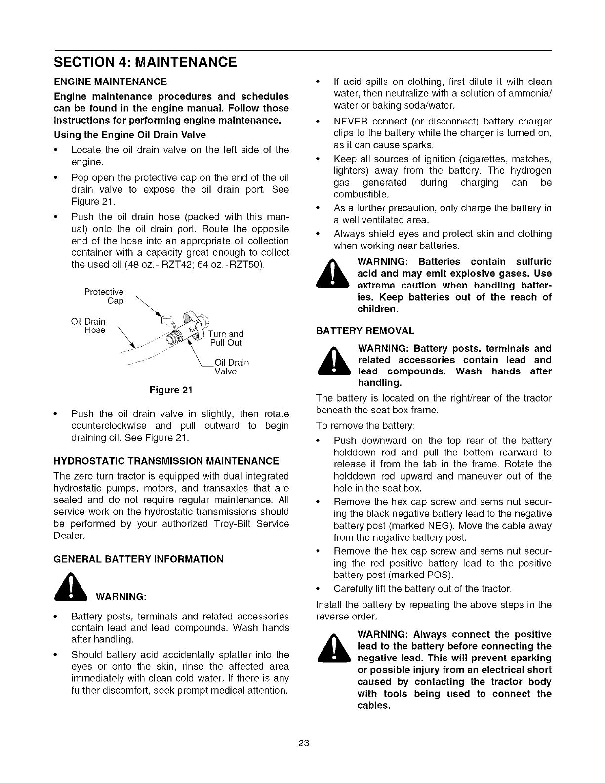
Using the Engine Oil Drain Valve
• Locate the oil drain valve on the left side of the
engine.
• Pop open the protective cap on the end of the oil
drain valve to expose the oil drain port. See
Figure 21.
• Push the oil drain hose (packed with this man-
ual) onto the oil drain port. Route the opposite
end of the hose into an appropriate oil collection
container with a capacity great enough to collect
the used oil (48 oz.- RZT42; 64 oz.-RZT50).
Protective
Cap _
Oil Drain _:::_ _
nose _ ._ _ '_STurnand
...._ _._"_ Pull Out
............. _Oil Drain
Valve
Figure 21
• Push the oil drain valve in slightly, then rotate
counterclockwise and pull outward to begin
draining oil. See Figure 21.
HYDROSTATIC TRANSMISSION MAINTENANCE
The zero turn tractor is equipped with dual integrated
hydrostatic pumps, motors, and transaxles that are
sealed and do not require regular maintenance. All
service work on the hydrostatic transmissions should
be performed by your authorized Troy-Bilt Service
Dealer.
GENERAL BATTERY INFORMATION
WARNING:
Battery posts, terminals and related accessories
contain lead and lead compounds. Wash hands
after handling.
Should battery acid accidentally splatter into the
eyes or onto the skin, rinse the affected area
immediately with clean cold water. If there is any
further discomfort, seek prompt medical attention.
If acid spills on clothing, first dilute it with clean
water, then neutralize with a solution of ammonia/
water or baking soda/water.
NEVER connect (or disconnect) battery charger
clips to the battery while the charger is turned on,
as it can cause sparks.
Keep all sources of ignition (cigarettes, matches,
lighters) away from the battery. The hydrogen
gas generated during charging can be
combustible.
As a further precaution, only charge the battery in
a well ventilated area.
Always shield eyes and protect skin and clothing
when working near batteries.
WARNING: Batteries contain sulfuric
,a,
BATTERY REMOVAL
The battery is located on the right/rear of the tractor
beneath the seat box frame.
To remove the battery:
• Push downward on the top rear of the battery
• Remove the hex cap screw and sems nut secur-
• Remove the hex cap screw and sems nut secur-
• Carefully lift the battery out of the tractor.
Install the battery by repeating the above steps in the
reverse order.
acid and may emit explosive gases. Use
extreme caution when handling batter-
ies. Keep batteries out of the reach of
children.
related accessories contain lead and
WARNING: Battery posts, terminals and
lead compounds. Wash hands after
handling.
holddown rod and pull the bottom rearward to
release it from the tab in the frame. Rotate the
holddown rod upward and maneuver out of the
hole in the seat box.
ing the black negative battery lead to the negative
battery post (marked NEG). Move the cable away
from the negative battery post.
ing the red positive battery lead to the positive
battery post (marked POS).
WARNING: Always connect the positive
lead to the battery before connecting the
negative lead. This will prevent sparking
or possible injury from an electrical short
caused by contacting the tractor body
with tools being used to connect the
cables.
23
Page 24

CHARGINGTHEBATTERY
Testand,if necessary,rechargethebatteryafterthe
tractorhasbeenstoredforaperiodoftime.
• A voltmeteror loadtestershouldread12.6volts
(DC)orhigheracrossthebatteryterminals.
• Chargethebatterywitha12-voltbatterycharger
ataMAXIMUMrateof10amps.
Voltmeter State of Charging
Reading Charge Time
12.7 100% Full Charge
12.4 75% 90 Min.
12.2 50% 180 Min.
12.0 25% 280 Min.
BATTERY MAINTENANCE
The battery is filled with battery acid and then sealed
at the factory. However, even a "maintenance free"
battery requires some maintenance to ensure its
proper life cycle.
• Spray the terminals and exposed wire with a
battery terminal sealer, or coat the terminals with
a thin coat of grease or petroleum jelly, to protect
against corrosion.
• Always keep the battery cables and terminals
clean and free of corrosion.
• Avoid tipping. Even a sealed battery will leak
electrolyte when tipped.
BATTERY STORAGE
• When storing the tractor for extended periods,
disconnect the negative battery cable. It is not
necessary to remove the battery.
• All batteries discharge during storage. Keep the
exterior of the battery clean, especially the top. A
dirty battery will discharge more rapidly.
• The battery must be stored with a full charge. A
discharged battery can freeze sooner than a
charged battery. A fully charged battery will store
longer in cold temperatures than hot.
• Recharge the battery before returning to service.
Although the tractor may start, the engine charging
system may not fully recharge the battery.
SERVICING ELECTRICAL SYSTEM
A fuse is installed to protect the tractor's electrical
system from damage caused by excessive amper-
age. Always use the same capacity fuse for
replacement. If the electrical system does not func-
tion, check for a blown fuse. See Figure 22
If you have a recurring problem with blown fuses,
have the tractor's electrical system checked by your
authorized Troy-Bilt Service Dealer.
GOOD BAD
Figure 22
Relays and Switches
There are several relays and safety switches in the
electrical system. If a function of the safety interlock
system described earlier is not functioning properly,
have the electrical system checked by your
authorized Troy-Bilt Service Dealer.
LUBRICATION
• Using a pressure lubricating gun, lubricate the
front castor axles and pivot axle with a No. 2
multi-purpose grease after every 10 hours of
service.
• Refer to the "MOWER DECK" section later in this
manual for deck lubrication procedures.
• Periodically lubricate all other pivot points with a
quality lubricating oil.
TIRE MAINTENANCE
Check the tire air pressure after every 50 hours of
operation or weekly. Keep the tires inflated to the
recommended pressures. Improper inflation will
shorten the service life of a tire. See the tire side wall
for proper inflation pressures. Observe the following
guidelines:
• Do not inflate a tire above the maximum pressure
shown on the sidewall of the tire.
• Do not reinflate a tire that has been run flat or
seriously under inflated. Have a qualified tire
mechanic inspect and service the tire.
24
Page 25

USING THE TRANSMISSION BYPASS RODS
If for any reason the tractor will not drive or you wish
to move the tractor, the two hydrostatic transmis-
sions are equipped with bypass rod that will allow you
to manually move the tractor short distances.
,_ WARNING: Do not tow the tractor, even
with the bypass rod engaged. Serious
transmission damage will result from
doing so.
• From just in front of the two rear tires, locate the
transmission bypass rods. See Figure 23.
• Pull one rod toward the front of the tractor until
the flange on the rod is forward of the keyhole
slot in the frame assembly.
• Lower the bypass rod into the keyhole slot and
release so the rod flange is against the front of
the frame bracket.
• Repeat the above procedure to engage the other
bypass rod.
RH Transmission
Bypass
Pull out
Rod
TRACTOR CREEPING
Creeping is the slight forward or backward movement
of the tractor when the engine is running at high idle
and the drive control levers are opened out in the
neutral position.
If after operating the tractor for some time, it begins to
creep while in the neutral position, adjust the
transmission control rods as follows.
• Place the front of the tractor against an
immovable object (e.g. wall, post, etc.).
• Jack up the rear of the tractor so that both rear
wheels are approximately one inch of the ground.
• With the engine running at high idle and the drive
control levers opened out in the neutral position,
and the parking brake disengaged, check the rear
wheels for rotation.
• If only one wheel is rotating, locate the transmis-
sion control rod beneath the frame at the front of
the rear tire. If both wheels rotate, locate both
control rods. See Figure 24.
RH Transmission Internal
Control Rod Pin
\\
i_ Then LowerIn Slot
Figure 23
• After moving the tractor, disengage both bypass
rods. Lift the rod and guide the flange of the rod
back through the larger circular opening of the
keyhole, then release the rod.
IMPORTANT: The tractor will not drive with the
bypass rods in the engage position.
f
\\ i
Transmission
Control Arm
Figure 24
• Remove the internal cotter pin securing the
ferrule to the transmission control arm and
withdraw the ferrule. Wheel rotation should stop.
If it does not, contact your authorized Troy-Bilt
Service Dealer.
• If the rotation stops, adjust the ferrule up or down
the control rod as necessary to align with the hole
in the transmission control arm. Re-insert the
ferrule into the hole in the control arm and secure
with the internal cotter pin.
• If necessary, repeat the previous two steps to
adjust the other transmission control rod.
• Lower the tractor and remove the jack.
25
Page 26

TRACTORHIGHSPEEDTRACKING
Ifthetractortrackstoonesidewithbothdrivecontrol
leversfully forward,adjustthe controlleversas
follows:
Checkfor properand balancedair pressurein
both front and rear tires. Refill tires if necessary.
Perform the first three steps in the previous sub-
section, Tractor Creeping, to verify that the tractor
is not creeping. If creeping, adjust following the
instructions in that sub-section.
• Recheck the tracking after making any adjust-
ments to the transmission control rods.
• If uneven tracking persists, note which direction
the tractor is tracking.
- If the tractor tracks to the right, adjust the
control lever stop bolt on the left side.
- If the tractor tracks to the left, adjust the control
lever stop bolt on the right side.
• Locate the applicable stop bolt on the left or right
console. See Figure 25.
TRANSMISSION DRIVE BELT
If the transmission drive belt becomes worn and
causes the drive transmissions to slip, the drive belt
must be replaced. To replace the drive belt, proceed
as follows:
• Remove the deck drive belt from the PTO clutch
on the bottom of the engine following the instruc-
tions in Deck Removal, SECTION 5: MOWER
DECK.
• From beneath the rear of the tractor, insert a 3/8
inch drive ratchet into the square hole of the drive
idler bracket. See Figure 26.
Transmission
Drive Pulley
iii iii
Console
Jam Nut
i
Figure 25
• Loosen the jam nut on the stop bolt, then turn the
stop bolt counterclockwise to make it longer.
Recheck the tracking and fine tune the adjust-
ment as necessary.
NOTE: If the stop bolt is adjusted too far, the
tracking problem will change sides. Make fine
tuning adjustments by shortening the same bolt.
• Tighten the jam nut against the console and repo-
sition the control lever if necessary.
Sq
Hole
Idler
Bracket
Engine
Idler Brkt. Pulley
Spring
Drive
Belt
Pulley
Figure 26
• Using the ratchet for leverage, pivot the idler
bracket and idler pulley away from the backside
of the 'V" belt; then lift the belt off and above the
engine pulley and off the idler pulley.
• With the belt loose, lift the belt off, up and over
the two transmission drive pulleys. Remove the
belt from the engine and idler pulleys.
• Loop the new belt and slide over and onto the
two transmission pulleys.
• Route the belt above the idler bracket back to the
engine drive pulley. Lift the belt over the PTO pul-
ley and above the engine drive pulley.
• Using the ratchet for leverage, pivot the idler
bracket and idler pulley against the spring ten-
sion; then slip the belt down into the engine drive
pulley and onto the idler pulley.
• Release the idler bracket so that the idler pulley
tightens against the back side of the belt and ten-
sions the drive belt.
• Reinstall the deck drive belt.
26
Page 27

TRACTOR STORAGE
If your tractor is not going to be operated for an
extended period of time (thirty days to approximately
six months), the tractor should be prepared for stor-
age. Store the tractor in a dry and protected location.
If stored outside, cover the tractor (including the tires)
to protect it from the elements. The procedures out-
lined below should be performed whenever the tractor
is placed in storage.
1. Change the engine oil and filter following the
instructions provided in the engine information at
the back of this manual.
WARNING: Never store the tractor with
fuel in the tank indoors or in poorly ven-
tilated enclosures, where fuel fumes may
reach an open flame, spark or pilot light
as on a furnace, water heater, clothes
dryer, etc.
Emptying the fuel system:
• Prior to putting the tractor in storage, monitor
fuel consumption with the goal of running the
fuel tank empty.
• Run the engine until it begins to stall. Use the
choke to keep the engine running until all fuel in
the carburetor has been exhausted.
3.
Clean the engine and the entire tractor
thoroughly.
4.
Fully charge the battery, then disconnect the neg-
ative cable at the battery to prevent possible
discharge. Recharge the battery periodically
when in storage.
NOTE: Remove the battery if exposed to prolonged
periods of sub-freezing temperatures. Store in a cool,
dry location where temperatures are above freezing.
5. Lubricate all lubrication points.
,_ WARNING: Fuel left in the fuel tank dete-
riorates and will cause serious starting
problems.
2.
If storing the tractor for 30 days or more:
To prevent gum deposits from forming inside the
engine's carburetor and causing possible malfunc-
tion of the engine, the fuel system must be either
completely emptied, or the gasoline must be
treated with a stabilizer to prevent deterioration.
Using a fuel stabilizer:
• Read the product manufacturer's instructions
and recommendations.
• Add to clean, fresh gasoline the correct amount
of stabilizer for the capacity (approximately 3
gallons) of the fuel system.
• Fill the fuel tank with treated fuel and run the
engine for 2-3 minutes to get stabilized fuel into
the carburetor.
NOTE: We do not recommend the use of a pressure
washer or garden hose to clean your uniL They may
cause damage to electrical components; spindles;
pulleys; bearings; or the engine. The use of water will
result in shortened life and reduce serviceability.
REMOVING THE TRACTOR FROM STORAGE
• Check the engine oil.
• Fully charge the battery and inflate the tires to the
recommended pressure.
• Add clean, fresh fuel.
• Start the engine and allow to idle for a few
minutes to ensure engine is operating properly.
• Drive the tractor without a load to make certain all
the tractor systems are functioning properly.
27
Page 28

SECTION 5: MOWER DECK
This section contains removal, installation, adjust-
ment, and maintenance information for the 42-inch
(RZT42) and 50-inch (RZT50) mower decks.
DECK REMOVAL
Remove the mower deck from the tractor as follows:
1. Move the tractor to a level surface, disengage the
PTO, stop the engine, and set the parking brake.
2. Move the deck gauge wheels to their highest
setting (lowest deck setting).
3. Remove the 'V' belt from the PTO pulley, located
on the bottom of the engine, using one of the
following two methods.
Releasing belt tension with the idler pulley.
• Using the deck lift handle, raise the deck to the
upper position that allows for the most horizontal
run of the belt between the deck idler pulleys and
the PTO pulley on the bottom of the engine.
• Working from the middle of the tractor, pivot the
idler bracket and movable idler pulley rearward
away from the backside of the 'V" belt just far
enough to lift the belt up and over the idler pulley.
See Figure 27.
42 INCH DECK SHOWN
Pull Idler Pulley
Rearward Movable Idler
Rolling the belt off the PTO pulley.
• Using the deck lift handle, raise the deck to the
upper position that allows for the most horizontal
run of the belt between the deck idler pulleys and
the PTO pulley on the bottom of the engine.
_ ARNING: The muffler at the rear of the
tractor may be extremely hot, and could
cause serious burns. Use extreme
caution when near the muffler, or allow
the muffler to fully cool before removing
the belt.
• Sitting behind the tractor facing forward, reach
beneath the tractor to grasp the belt at the front of
the PTO pulley.
,_ WARNING: Use caution to prevent
pinching your fingers when rolling the
belt off the PTO pulley.
Pull the left side of the belt rearward and down-
ward while manually turning the PTO pulley to the
right until the belt rides out onto the edge of the
lower sheave of the pulley. NOTE: If pulling the
right side of the belt. turn the pulley to the left.
While still holding the belt downward, continue
turning the PTO pulley until the belt is rolled off
the pulley.
4.
Lower the deck to the ground using the deck lift
handle.
5.
Locate the LH and RH deck support pins on each
side of the deck. Pull the deck support pins
outward and lock in the disengaged position to
release the deck from the tractor's LH and RH
deck lift arms. See Figure 28.
Fixed Idler
Pulley
'V' Belt / ,_.
Idler Bracket
Figure 27
_ ARNING: The muffler at the rear of the
tractor may be extremely hot, and could
cause serious burns. Use extreme
caution when near the muffler, or allow
the muffler to fully cool before removing
the belt.
• From beneath the rear of the tractor, slide the belt
off of the PTO pulley on the bottom of the engine.
28
Rear Deck Deck Lift Arm :
Hanger Bracket
\
\
i
Deck '\
Support ......,',\ Rear Hanger
Pin ,,',, Bracket Slot
Figure 28
6.
Raise the deck lift arms out of the rear hanger
bracket slots by raising the deck lift handle on the
tractor to its highest position.
Page 29

7. Slidethe deckforwardso thatthe deckfront
hangerrodcanbeliftedoutofthetwoslotsofthe
frontdeckbracket.Afterliftingthefronthanger
rodoutof theslots,slidethedeckrearwardso
thattherodcannolongerengagetheslots.
8. Usingcareto preventthe fronthangerrodfrom
fallingbackintothedeckslots,gentlyslidethe
cutting deck (from the right side) out from
underneaththetractor.
DECKINSTALLATION
Toinstallthemowerdeck,proceedasfollows:
1. While holdingup the deck fronthangerrod,
carefullyslidethedeckunderneaththerightside
ofthetractor.
2. Whilestillholdingthefronthangerrod,slidethe
deckforwarduntilthe fronthangerrodcanbe
loweredintotheslotsatthefrontofthedeck.
3. Lowerthefronthangerrodintothe slotsof the
frontdeckbracket,thenslidethedeckrearward.
4. Maneuverthedecksothatthe slotsinthe two
reardeck hangerbracketsapproximatelyalign
withthedecklift armsof the tractor.Referto
Figure28.
5. Usethedecklifthandleofthetractortolowerthe
decklift arms intothe slots of the reardeck
hangerbrackets.
6. Pullthedecksupportpinsoutwardandmaneuver
thedeckas necessaryto alignthe holesinthe
deckliftarmwiththepins.RefertoFigure28.
7. Whenaligned,pusheachpinfullyinwardthrough
theliftarmstosecurethearmsintherearhanger
bracketslots.
8. Makecertainthe'V' belt is in the spindle pulleys
on the deck, then route the belt rearward beneath
the tractor frame and above the two transmission
tubes
9. Install the 'V' belt onto the PTO pulley using one
of the following two methods.
Using the idler pulley to tension the belt.
• Using the deck lift handle, raise the deck to the
upper position that allows for the most horizontal
run of the belt between the deck idler pulleys and
the PTO pulley on the bottom of the engine.
• Route the backside of the belt around the fixed
idler pulley of the deck. Refer to Figure 27.
• Working from the middle of the tractor, pivot the
idler bracket/movable pulley rearward against the
spring tension and slide the backside of the belt
onto the movable idler pulley. Refer to Figure 27.
Rolling the belt into the PTO pulley.
• Using the deck lift handle, raise the deck to the
upper position that allows for the most horizontal
run of the belt between the deck idler pulleys and
the PTO pulley on the bottom of the engine.
• Make certain the belt is in the spindle pulleys of
the deck, and that the backside of the belt is
against both the fixed and movable idler pulleys.
Refer to Figure 27.
_ ARNING: The muffler at the rear of the
• Sitting behind the tractor, facing forward, make
_ ARNING: Use caution to prevent
tractor may be extremely hot, and could
cause serious burns. Use extreme
caution when near the muffler, or allow
the muffler to fully cool before removing
the belt.
certain the belt is not twisted; then reach beneath
the tractor to grasp the belt and pull it toward the
PTO pulley.
pinching your fingers when rolling the
belt off the PTO pulley.
Pull the right side of the belt rearward and place
the narrow V side of the belt into the right/front
side of PTO pulley. See Figure 29.
While holding the belt and pulley together, rotate
the pulley to the left (See Figure 29). Continue
holding and rotating the pulley and belt until the
belt is fully rolled into the PTO pulley. NOTE: If
using the left side of the belt, tum the pulley to
the righL
PTO Pulley
PTO Belt
_ ARNING: The muffler at the rear of the
• Install the belt in the PTO pulley on the bottom of
tractor may be extremely hot, and could
cause serious burns. Use extreme
caution when near the muffler, or allow
the muffler to fully cool before removing
the belt.
the engine.
Transmission
Tube
Figure 29
29
Page 30

LEVELINGTHEMOWERDECK
Whenleveledcorrectlythe mowerdeckshouldbe
levelsidetoside,andshouldbeapproximatelya 1/8
to1/4inchlowerinthefrontofthedeck.
Sideto SideLeveling
Ifthecuttingdeckappearstobemowingunevenly,a
sideto sideadjustmentcanbe performed.Adjustif
necessaryasfollows:
• Withthe tractorparkedon a firm,levelsurface,
placethedecklifthandleinthetopnotch(highest
position)androtatebothbladessothattheyare
perpendiculartothetractorframe.
• Measurethedistancefromtheoutsideleftblade
tip to the groundand the distancefrom the
outsideright blade tip to the ground.The
measurementsshouldbe equal.If they'renot,
proceedtothenextstep.
• Comparethetwomeasurementsasfollows:
- ModelRZT42--determinewhetherthe right
sideofthedeckmustberaisedorlowered.
- ModelRZT50--determinewhethertheleftside
ofthedeckmustberaisedorlowered.
• RZT42- 42InchDeckONLY
- Loosen,butdonotremove,thehexcapscrew
on the rightdeck hangerbracket.Referto
Figure30.
- Levelthe deckby usinga wrenchto turnthe
adjustmentgear(foundimmediatelybehindthe
hex cap screwjust loosened)clockwiseto
lower the right side of the deck, or
counterclockwiseto raisethe rightsideof the
deck.RefertoFigure30.
- Thedeckis properlyleveledwhenbothblade
tipmeasurementstakenearlierareequal.
Raise RT.
Side of Deck
A_djustment
Gear
Figure 30
Lower RT.
Side of Deck
Hex Cap
Screw
%
- Retighten the hex cap screw on the right deck
hanger bracket when proper adjustment is
achieved.
RZT50 - 50 Inch Deck ONLY
- Loosen, but do not remove, the hex cap screw
on the left deck hanger bracket. Refer to Figure
31.
- Level the deck by using a wrench to turn the
adjustment gear (found immediately behind the
hex cap screw just loosened) clockwise to raise
the left side of the deck, or counterclockwise to
lower the left side of the deck.
Lower LT. Raise LT.
Side of Deck
Adjustment Hex Cap
Gear Screw
Figure 31
- The deck is properly leveled when both blade
tip measurements taken earlier are equal.
- Retighten the hex cap screw on the left deck
hanger bracket when proper adjustment is
achieved.
Front to Back Leveling.
The front of the deck should be approximately 1/8 to
1/4 inch lower than the rear of the deck. Adjust if nec-
essary as follows:
• With the deck raised off of the ground, rotate the
blades so that they are parallel to the frame of the
tractor.
• If the side to side leveling was done correctly,
measuring just the right blade should be
acceptable to attain the correct back to front pitch
of the deck.
• Measure the distance from the front tip of the
blade to the ground and the distance from the
rear tip to the ground. The front distance should
be 1/8 to 1/4 inch less than the rear. If it is not,
proceed to the next step.
Side of Deck j
3O
Page 31

• Fromthefrontof the tractor,loosenthe outer
nutsonthedeckfronthangerrod,andturnthem
awayfromtheinnernuts.SeeFigure32.
Hex Nuts
Front Hanger
Rod Bracket
Front
Hanger
Rod
NOTE: The deck gauge wheels are an anti-scalp
feature of the deck and are not designed to support the
weight of the cutting deck.
Using the lift handle, set the deck in the desired
height setting, then check the gauge wheel and if
necessary adjust as follows.
• With the deck set at the desired height, visually
check the distance between the gauge wheels
and the ground. If the gauge wheels are near or
touching the ground, they should be raised. If the
gauge wheels are too high, they should be
lowered.
• Remove the lock nut securing one of the gauge
wheel shoulder screws to the deck. Remove the
gauge wheel and shoulder screw. See Figure 33.
42 INCHDECK
Figure 32
• If the front of the deck was too low, turn the inner
hex nuts clockwise against the hanger bracket to
shorten the front hanger rod and raise the front of
the deck. See Figure 32.
• If the front of the deck was too high, turn the hex
nuts counterclockwise to lengthen the front
hanger rod and lower the front of the deck.
IMPORTANT: The deck front hanger rod should
be at the front of the slots of the front deck
bracket. If one side of the rod is not at the front of
its slot, turn the inner hex nut on that side until
rod just touches the front of the sloL Then re-
measure and re-adjust the front hanger rod as
necessary.
When the correct pitch of the deck is acquired,
secure the inner hex nuts with a wrench and
tighten the outer hex nuts against the inner hex
nuts to lock them in the adjusted position.
ADJUSTING THE GAUGE WHEELS
The cutting height of the mower deck can be set in
any of six height settings using the deck lift handle of
the tractor. The deck heights range from 1-1/2 inches
to 4 inches. The deck gauge wheel position should be
approximately 1/4 to 1/2 inch above the ground when
the deck is set in the desired height setting.
Rear Gauge
Wheel _ Gauge
_ __Wheel
,_, _ _/ _ Bracket
Shoulder \ /_,!--._:_ DeckAdjustment
Screw _ L_-._ _lndex Holes
__ Lock
Nut
50 INCH DECK
Shoulder
Screw
--_::_" Front Gauge
Rear Gauge
Wheel
$1 Wheel Nut
Screw Bracket
Gauge .i Wheel
Wheel
Bracket
Index
Holes Gau_e Lock
Figure 33
• Insert the shoulder screw in the one of four index
holes that will give the gauge wheel a 1/4 to 1/2
inch clearance with the ground.
• Note the index hole of the just adjusted wheel,
and adjust the other gauge wheels into the
respective index holes on the other gauge wheel
brackets on the deck.
from the discharge opening of the
WARNING: Keep hands and feet away
cutting deck.
31
Page 32

DECK MAINTENANCE
Cleaning And Blade Care
WARNING: Before performing any main-
tenance, place the PTO switch in the
"OFF" position, engage the parking
brake lever, turn the ignition key to the
"OFF" position and remove the key from
the switch. When servicing the mower
deck, be careful not to cut yourself on
the sharpened blades.
Clean the underside of the mower deck at the end of
the mowing season or when buildup of cut material
on the underside is noticed.
Once a month remove the belt covers to remove any
accumulation of grass clippings from around the
spindle pulleys and V-belt. Clean more often when
mowing tall, dry grass.
The cutting blades must be kept sharp at all times.
Sharpen the cutting edges of the blades evenly so
that the blades remain balanced and the same angle
of sharpness is maintained.
If the cutting edge of a blade has already been sharp-
ened many times, or ifany metal separation is present,
it is recommended that new blades be installed. New
blades are available at your authorized dealer.
The blades may be removed as follows.
• Remove the deck from beneath the tractor, (refer
to Deck Removal on page 28) then gently flip the
deck over to expose its underside.
Use a 15/16 inch wrench to hold the hex nut on
top of the spindle assembly when loosening the
hex nut securing the blade. A block of wood may
be placed between the deck housing and the
cutting edge of the blade to help in breaking
loose the hex nut securing the blade. Refer to
Figure 34.
HEX FLANGE NUT J
WOOD
BLOCK
SPINDLE ASSEMBLY
Figure 34
• When reinstalling the blades, be sure they are
installed so that the wind wings are pointing
upward toward the top of the deck.
• Reinstall the deck (refer to Deck Installation on
page 29).
32
Page 33

DECK LUBRICATION
• After every 10 hours of operation and/or before
putting the deck into winter storage, lubricate
the spindle assemblies with a No. 2
multipurpose lithium grease. The lube fittings
are located in the spindle housing and can be
accessed from underneath the deck.
42 INCH MOWER DECK
REPLACING THE DECK DRIVE BELT
• Remove the deck from beneath the tractor, (refer
to Deck Removal on page 28).
• Remove the hex tapping screws securing the belt
covers to the deck and remove the belt from the
spindle pulleys. Refer to Figure 35.
• Depending on which deck (42" or 50") you are
working on, install the new belt around the
spindle pulleys as shown in the applicable
graphic of Figure 35. Reinstall the belt covers.
• Route the belt rearward between the two idler
pulleys and reinstall the deck following the
instructions in Deck Installation on page 29.
Belt
Belt
Idler Pulley
Cover
Idler Pulley
50 INCH MOWER DECK
'V' Belt
Cover
Idler Pulley
Idler Pulley
Figure 35
33
Page 34

SECTION 6: PARTS LIST RZT42 AND RZT50
REF. PART
NO. NUMBER
1 603-04303B
777122489
2
703-05829
3
710-0520
4
710-3005
5
712-04065
6
732-0626
7
738-04058
8
738-04162A
9
756-04129
DESCRIPTION QTY,
Frame Assembly ............................. 1
Graphic, Release Lever ............... 2
Idler Arm, Drive ............................... 1
Screw, Hex Cap, 3/8-16 x 1.5 GR5 3
Screw, Hex Cap, 3/8-16 x 1.25 GR5 1
Nut, Hx Insert Flnge Lck, 3/-16 GrF 4
Spring, Extension, .75 x 5.06 .......... 1
Spacer, Shoulder, .39 x 1.0 x .7 ...... 2
Screw, Shoulder, .884 x .19 ........... 1
Pulley, Idler, 4.25 Dia...................... 1
REF.
NO.
1
2
3
4
5
6
7
8
9
10
11
12
13
14
15
PART
NUMBER
603-04148A
603-04308
634-04237
710-04186
710-0514
711-04228
712-3022
731-05500
736-0169
736-0227
736-0250
737-3000
738-04182
741-0516B
741-0990B
DESCRIPTION QTY
Axle, Front Pivot .......... 1
Bracket, Castor Wheel 2
Wheel Assembly .......... 2
11.0 x 4.0 x 5.0
Screw, Hex Lock ......... 2
1/2-13 x 1.25 GR5
Screw, Hex Cap .......... 2
3/8-16 x 1.0 GR5
Shaft, Axle ................... 1
Nut, Hex Lock .............. 2
1/2-13 GRB
Bearing, Flange ........... 6
1.0 x 1.246
Washer, Lock, 3/8 ....... 2
Washer, Flat ................ 2
.39 x 1.5 x .134 .........
Washer, Flat ................. 2
1.0 x 1.75 x.107
Fitting, Lube, 3/16 Drive 3
Screw, Shoulder ........... 2
.75 x 4.75:7/16-14
Bearing, Flange ............ 2
.76 x 1.0 x 1.2
Bearing, Flange ........... 2
.76 ID w/Lube Ftg.
©
NOTE: For painted parts, please refer to the list of
color codes below. Please add the applicable color
code, wherever needed, to the part number to order
a replacement part.
For instance, if a part, numbered 700-xxxx, is paint-
ed red metalic, the part number to order would be
700-xxxx-0650.
Red : 0638
Oyster Grey: 0662
Powder Black: 0637
34
Page 35

MODELS RZT42 AND RZT50
REF. PART
NO. NUMBER
1 710-1268
2 712-04063
3 712-04064
4 720-0309A
5 726-0201
6 731-04074
7 732-0499
8 732-1184
DESCRIPTION QTY. NO.
FIEF.
Screw, Hx. Wash. Hd. Tapp ............ 2 9
#10-16 x .375 10
Nut, Hx Insert Flange Lck................ 2 11
5/16-18 GrF 12
Nut, Hx Insert Flnge Lck, 1/4-20 GrF 1 13
Grip, Seat Adjustment ..................... 1 14
Nut, Speed, .3125 ........................... 2 15
Spacer, Seat Adjustment ................ 4 16
Spring, Compression, .41 x 1.5 ....... 1 17
Spring, Extension, .84 Dia. x 4.6 ..... 1 18
PART
NUMBER
736-0275
736-3019
738-0137A
738-0296
738-0966A
783-0209D
783-0611
783-0738C
783-0739A
783-0753
%
DESCRIPTION
QTY.
Washer, Flat, .344 x .688 x .065 .....
Washer, Flat, .531 x 1.062 x .134 HT
Screw, Shoulder, .34 x .285:1/4-20
Screw, Shoulder, .437 x .268:5/16-18
Screw, Shoulder, .5 x .925:3/8-16 ...
Bracket, Seat Lift ............................. 1
Stop, Seat Adjustment .................... 1
Bracket, Seat Pivot .......................... 1
Lever, Seat Adjustment ................... 1
Index Bracket, Seat Adjustment ...... 1
3
2
1
2
4
35
Page 36
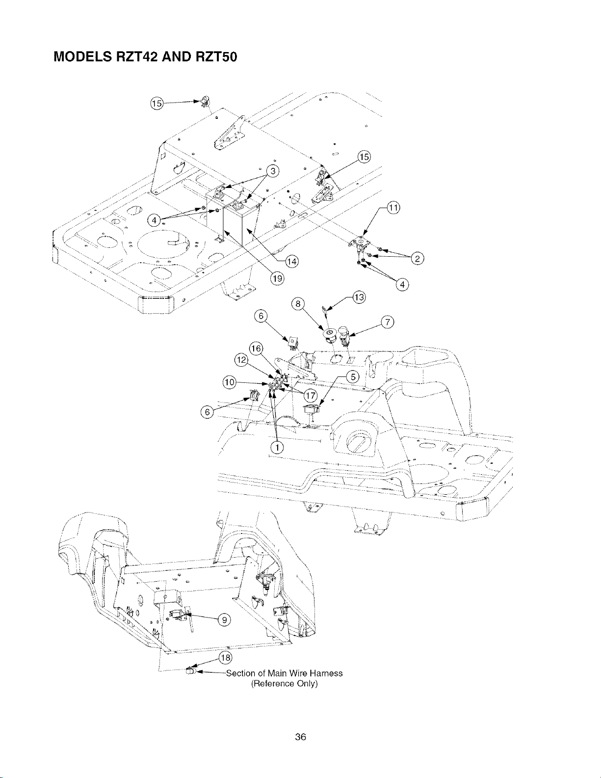
MODELS RZT42 AND RZT50
\
\ t
tt
f
Section of Main Wire Harness
(Reference Only)
36
Page 37

MODELS RZT42 AND RZT50
REF, PART
NO. NUMBER
1 710-0227
710-0599
3 710-3015
4 712-0271
5 725-04022A
6 725-04165
7 725-04174
8 725-04228
9 725-04232
10 725-1303
11 725-1426A
12 725-1439
13 925-1745
14 725-1707D
15 725-3166
16 726-0278
17 726-0279
18 726-0470
19 747-04425
t 725-04297
t 725-04188
DESCRIPTION QTY,
Screw, Hex Wash. Hd. Tapp ............ 2
#8-18 x .5
Screw, Hex Wash. Hd. Tapp ............ 2
1/4-20 x .5
Screw, Hex Cap, 1/4-20 x .75 GR5 .. 2
Nut, Hex Sems, 1/4-20 ..................... 4
Meter, Hour ...................................... 1
Switch, Dbl. Pole - Neutral ............... 2
Switch, PTO ..................................... 1
Switch, Ignition ................................. 1
Switch, 3-Pole, (NC-NO-NO) - Brake 1
Switch, Outer Seat Spring ................ 1
Solenoid ........................................... 1
Switch, Inner Seat Spring ................. 1
Key ................................................... 1
Battery, 235 CCA ............................. 1
Switch, Snap Mount (N.C.) - Reverse 2
Plate, Insulator Boss ........................ 1
Plate, Insulator ................................. 2
Tie, Cable ......................................... 2
Rod, Battery Holddown .................... 1
Harness Assembly, Wire .................. 1
Cable Wire, Black - to Ground ......... 1
t NOT SHOWN
37
Page 38
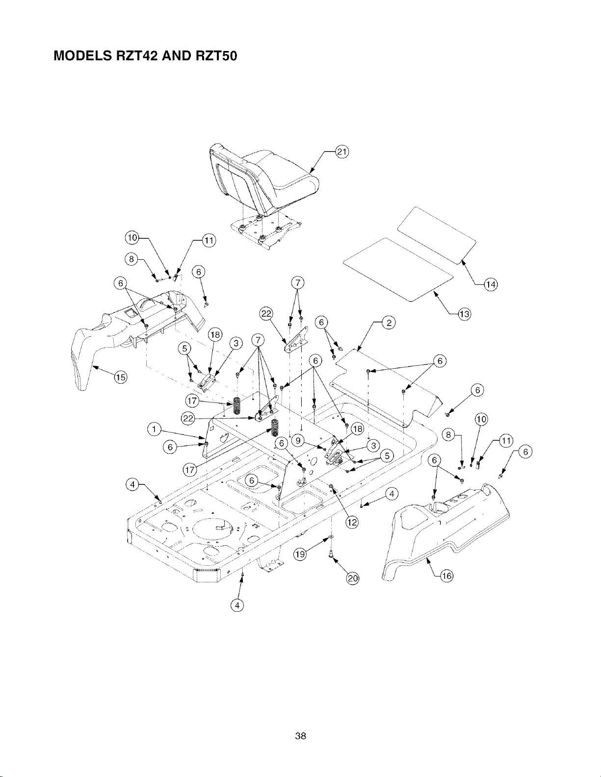
MODELS RZT42 AND RZT50
38
Page 39

MODELS RZT42 AND RZT50
REF,
PART
NO.
NUMBER
1
603-04326
777122600
777S32354
777122307
2
703-05373A
777D09987
3
703-05467
4
710-04261
5
710-0599
6
710-0604A
7
710-0726
8
710-0778
9
710-1268
10
712-0298
11
712-04092
12
712-0431
13
723-04020
14
723-04021
15
731-04662B
777122608
777D09986
777122305
777122309
16
731-04663A
777122609
777D09985
17
732-04035
18
732-04200
19
736-0300
2O
738-0430
21
757-04010
22
783-1489B
DESCRIPTION QTY
Frame, Seat Box ............................... 1
Graphic, Park Brake ....................... 1
Graphic, Warning ........................... 1
Graphic, Deck Height ..................... 1
Bracket, Foot Rest ............................ 1
Graphic, Troy-Bilt ........................... 1
Bracket, Switch Mounting .................. 2
Screw, Hex Wash. Hd Tapp .............. 4
#12-16 x .50
Screw, Hex Wash. Hal. Tapp ............. 4
1/4-20 x .5
Screw, Hex Wash. Hal. Tapp ............. 20
5/16-18 x .625
Screw, Hex Wash. Hd. Tapp ............. 6
5/16-12 x .75
Screw, Hex Wash. Hd. Tapp ............. 2
1/4-20 x 1.5
Screw, Hex Wash. Hd Tapp .............. 2
#10-16 x .375
Nut, Hex Jam, 1/4-20 GR2 ................ 2
Nut, U Type Speed, 1/4-20 ............... 2
Nut, Hex Flange Lock, 3/8-16 GRF 2
Pad, Abrasive Foot Plate .................. 1
Pad, Abrasive Toe Plate ................... 1
Console, LH ...................................... 1
Graphic, Instruction ........................ 1
Graphic, Troy-Bilt ........................... 1
Graphic, Throttle Control 42". ......... 1
Graphic, Throttle Control 50" ......... 1
Console, RH ...................................... 1
Graphic, Instruction ........................ 1
Graphic, Troy-Bilt ........................... 1
Spring, Compression, 1.28 x 3.125 2
Spring, Switch Actuator ..................... 2
Washer, Flat, .406 x .875 x .059 ....... 2
Screw, Shoulder, .50 x .685:3/8-16 ... 2
Seat ................................................... 1
Bracket, Seat Pivot ............................ 2
39
Page 40

MODELS RZT42 AND RZT50
4O
Page 41

MODELS RZT42 AND RZT50
REF. PART
NO. NUMBER
1 603-04160A
2 603-04322
3 603-04324
4 703-05387A
5 703-05396
6 703-05414A
7 703-05793
8 710-0433
9 710-0805
10 710-3005
11 710-3105
12 710-3144
13 710-3180
14 711-0832
15 712-3048
16 712-04063
17 712-04065
18 712-0431
19 712-3007
20 712-3008
21 714-0104
22 714-3020
23 716-0106
24 720-0274
25 720-0311
26 720-04072
27 731-04735
28 732-0334
29 732-0874
30 732-04350
31 736-0270
32 736-0425
33 736-3019
34 738-0143
35 738-0296
36 741-0225
37 741-3074
38 746-0970
39 747-04224
40 747-04225A
41 747-04226
42 747-04401A
43 747-04491
44 748-04052
DESCRIPTION QTY.
Shaft Assembly, Deck Lift ................... 1
Lever, Lapbar, RH ............................... 1
Lever, Lapbar, LH ............................... 1
Bracket, Lapbar Pivot .......................... 2
Handle, Brake ..................................... 1
Bracket, Front Deck Hanger ................ 1
Arm, Deck Lift ...................................... 2
Screw, Hex Lock, 1/4-20 x .62 GR5 .... 2
Screw, Hex Cap, 5/16-18 x 1.5 GR5 ... 2
Screw, Hex Cap, 3/8-16 x 1.25 GR5 ... 1
Bolt, Carriage, 5/16-18 x .875 ............. 2
Screw, Hex Cap, 3/8-16 x 2.0 GR5 ..... 2
Screw, Hex Cap, 5/16-18 x 1.75 GR5 2
Ferrule, 3/8-24 x .375 .......................... 2
Nut, Hex Jam, 1/2-13 GR5 .................. 4
Nut, Hx Flange Insert Lck, 5/16-18 GrF 6
Nut, Hx Flange Insert Lck, 3/8-16GrF 2
Nut, Hex Flange Lock, 3/8-16 GRF 5
Nut, Hex Jam, 5/16-18 GR5 ................ 2
Nut, Hex Jam, 3/8-16 GR5 .................. 2
Pin, Internal Cotter .............................. 6
Pin, Internal Cotter .............................. 1
E-Ring, .625 Dia. Shaft ...................... 4
Grip, Hand ........................................... 2
Grip, Handle ........................................ 1
Knob, Nut, 5/16-18 Nylon Lock ........... 2
Grip, Handle ........................................ 1
Spring, Compression ........................... 1
Spring, Torsion .................................... 1
Spring, Compression ........................... 2
Washer, Bell, .265 x .75 x .062 ........... 2
Washer, Bell, .325 x .93 x .045 ........... 2
Washer, Fiat, .531 x 1.062 x .134 HT .. 2
Screw, Shoulder, .498 x .340:3/8-16 4
Screw, Shoulder, .437 x .268:5/16-18 2
Bearing, Hex Flange ........................... 6
Bearing, Flange, .626 x .938 x .344 .... 2
Cable, Deck Lift, 5.05 Long ................. 2
Rod, Deck Lift Handle ......................... 1
Rod, Lapbar Control ............................ 2
Shaft, Control ...................................... 2
Rod, Deck Front Hanger ..................... 1
Rod, Brake .......................................... 2
Hub, Control ........................................ 2
41
Page 42

MODEL RZT42
42
Page 43

MODEL RZT42
FIEF.
PART
NO.
1
2
4
5
6
7
NUMBER
603-04156
603-04335
777S32599
777S30503
777122281
618-0427
756-1188
703-05824
710-0347
710-0528
710-0599
DESCRIPTION QTY.
Bracket, Deck Lift ............................. 1
Housing, Deck .................................. 1
Graphic, Danger ............................ 1
Graphic, Danger ............................ 1
Graphic, Instruction ....................... 1
Spindle Assembly ............................. 1
Pulley ............................................. 1
Arm, Idler .......................................... 1
Screw, Hex Cap, 3/8-16 x 1.75 GR5 2
Screw, Hex Cap, 5/16-18 x 1.25 GR5 1
Screw, Hex Wash. Hd. Tapp ............ 5
1/4-20 x .5
710-0650
Screw, Hex Wash. Hd. Tapp ............ 8
5/16-18 x .875
710-0726
Screw, Hex Wash. Hd. Tapp ............ 4
5/16-12 x .75
10
710-0751
11
710-3005
12
710-3180
13
711-04069
14
712-0324
15
712-04064 Nut, Hx Insert Flange Lck, 1/4-20 GR5 2
16
712-04065 Nut, Hx Insert Flange Lck, 3/8-16 GrF 3
17
712-0417A Nut, Hex Flange, 5/8-18 ................... 2
18
712-0429 Nut, Hex Insert Lock, 5/16-18 GR5 .. 1
19
712-0431 Nut, Hex Flange Lock, 3/8-16 GrF .... 2
2O
712-0641 Nut, Hex, M16-1.5 ............................ 1
21
712-3010 Nut, Hex, 5/16-18 GR5 ..................... 1
22
714-0470
23
717-1553B
24
726-0233
25
731-1032B
777S30284
26
731-2231B
27
732-0306
28
732-0459
29
734-04155
30
736-0119
31
736-0760
32
736-3072
33
738-04146
34
738-04162A
35
738-3056
36
942-0616A
37
747-1116
38
754-04045
39
756-04129
40
783-1146A
Screw, Hex Cap, 1/4-20 x .62 GR5 .. 2
Screw, Hex Cap, 3/8-16 x 1.25 GR5 1
Screw, Hex Cap, 5/16-18 x 1.75 GR5 1
Pin, Grass Catcher, 1/4-20 ............... 1
Nut, Hex Insert Lock, 1/4-20 GR8 .... 1
Pin, Cotter, 1/8 x 1.25 ....................... 2
Gear, Deck Adjustment .................... 1
Nut, Push, .25 x .5 ............................ 2
Chute Assembly, Discharge ............. 1
Graphic, Danger 1
Cover, Belt ........................................ 2
Spring, Compression ........................ 2
Spring, Extension, .94 Dia. x 6.74 .... 1
Wheel, Deck Ball, 5.0 ....................... 2
Washer, Lock, 5/16 ........................... 1
Washer, Lock .................................... 1
Washer, Flat, .38 x .93 x .11 HT ....... 2
Plug, Screw, M16 x 1.5 ..................... 1
Spacer, Shoulder, .884 x .19 ............ 1
Screw, Shoulder, .5 x 2.5:3/8-16 2
Blade, 3 in 1,21.23 ........................... 2
Rod, Deck Hanger ............................ 2
Belt, V, Type A Sec x 109 ................. 1
Pulley, Idler, 4.25 Dia ....................... 2
Skirt, Deck ........................................ 1
43
Page 44

MODEL RZT50
44
½
Page 45

MODEL RZT50
REF.
NO.
1
2
3
4
5
6
7
8
9
10
11
12
13
14
15
16
17
18
19
2O
21
23
24
25
26
27
28
29
3O
31
32
33
34
35
36
37
38
39
40
41
42
43
44
PART
NUMBER
603-04328
777S32598
777S30503
777122282
618-04126
756-1171
737-3000
631-04070
777S30284
683-0254
703-05825
703-3279
703-3511
710-0347
710-0528
710-0599
710-0726
710-1260A
710-3005
710-3168
710-3178
712-04065
712-0417A
712-0431
712-0641
714-0470
717-1553B
732-0306A
732-0459
734-04155
736-0119
736-0407
736-0760
736-3072
738-04146
738-04162A
738-3056
742-04053A
747-1116
754-04044
756-04129
783-04399
783-04400
783-04414
783-04415
731-3131A
783-04470
732-3070
711-1762
DESCRIPTION QTY.
Housing, Deck ..................................... 1
Graphic, Danger ............................... 1
Graphic, Danger ............................... 1
Graphic, Instruction .......................... 1
Spindle Assembly ................................ 3
Pulley, 5.39 Dia ................................ 3
Fitting, Lube, 3/16 Drive ................... 3
Chute Assembly, Discharge ................ 1
Graphic, Danger ............................... 1
Bracket, Deck Hanger ......................... 1
Arm, Idler ............................................. 1
Bracket, Stop ....................................... 1
Guard, Finger ...................................... 1
Screw, Hex Cap, 3/8-16 x 1.75 GR5 ... 3
Screw, Hex Cap, 5/16-18 x 1.25 GR5 . 1
Screw, Hex Wash. Hd. Tapp ............... 7
1/4-20 x .5
Screw, Hex Wash. Hd. Tapp ............... 6
5/16-12 x .75
Screw, Hex Wash. Hd. Tapp ............... 12
5/16-18 x .75
Screw, Hex Cap, 3/8-16 x 1.25 GR5 1
Screw, Carriage, 3/8-16 x 1.0 .............. 1
Screw, Carriage, 3/8-16 x .75 .............. 4
Nut, Hx Insert Flange Lck, 3/6-16 GrF 9
Nut, Hex Flange, 5/8-18 ...................... 3
Nut, Hex Flange Lock, 3/8-16 GRF ..... 4
Nut, Hex, M16-1.5 ............................... 2
Pin, Cotter, 1/8 x 1.25 .......................... 2
Gear, Deck Adjustment ....................... 1
Spring, Compression ........................... 2
Spring, Extension, .94 Dia. x 6.74 ....... 1
Wheel, Deck Ball, 5.0 .......................... 4
Washer, Lock, 5/16 .............................. 1
Washer, Bell, .45 x 1.0 x .062 .............. 1
Washer, Lock ....................................... 2
Washer, Flat, .38 x .93 x. 110 HT ........ 3
Plug, Screw, M16 x 1.5 ........................ 2
Spacer, Shoulder, .884 x .190 ............. 1
Screw, Shoulder, .5 x 2.5:3/8-16 ......... 4
Blade, 2 in 1, 17.9 Lg ........................... 3
Rod, Deck Hanger ............................... 2
Belt V, Type A Sec x 134 ..................... 1
Pulley, Idler, 4.25 Dia .......................... 3
Cover, Belt LH ..................................... 1
Cover, Belt RH ..................................... 1
Skirt, Center ......................................... 1
Skirt, RH .............................................. 1
Chute, Deflector ................................... 1
Bracket, Chute Mounting ..................... 1
Spring, Torsion .................................... 1
Pin, Hinge ............................................ 1
45
Page 46

MODEL RZT42
46
Page 47

MODEL RZT42
REF.
NO.
1
2
3
4
5
6
7
10
11
12
13
14
15
16
17
18
19
2O
21
22
23
24
25
26
27
28
29
3O
31
32
PART
NUMBER
603-04176
751-10057C
751-3124B
703-05441A
703-05870
710-0227
710-04248
710-0599
710-0726
710-04261
710-1314A
710-1315
710-3008
710-3217
712-0142
712-04063
717-04183
721-0208
731-04914
736-0171
736-04131
737-0125
746-04161
747-04228A
751-10349
751-0564B
751-0617B
751-3140
751-3141
751-3142
756-0978A
726-3055
726-0205
DESCRIPTION QTY.
Tube, Exhaust .................................. 1
Tank, Fuel, 3.0 Gal ........................... 1
Cap, Fuel ....................................... 1
Bracket, Muffler Mounting ................. ' 1
Shield, Muffler Tube Heat ................. 1
Screw, Hex Wash. Hd. Tapp ............ 3
#8-18 x .5
Screw, Hex Cap, 7/16-20 x 4.0 GR5 1
Screw, Hex Wash. Hd. Tapp ............ 4
1/4-20 x .5
Screw, Hex Wash. Hd. Tapp ............ 2
5/16-12 x .75
Screw, Hex Wash. Hd. Tapp ............ 2
#12-16 x .5
Screw, Socket Hd. 5/16-18 x .75 ...... 2
Screw, Hex Wash. Hd. Tapp ............ 4
3/8-16 x 1.25
Screw, Hex Cap, 5/16-18 x .75 GR5 4
Screw, Truss Hd. Mach. #8-32 x .375 1
Nut, Hex, #8-32 ................................ 1
Nut, Hx Insert Flange Lck, 5/16-18 GrF 4
Clutch Assembly, Electric PTO ......... 1
Gasket, Exhaust (B&S- 272293) ...... 1
Knob, Throttle Control ...................... 1
Washer, Lock, 7/16 ........................... 1
Washer, Flat, .438 x 1.75 x .25 ......... 1
Fitting, Elbow .................................... 1
Cable, Throttle, 39.0 Lg .................... 1
Wire, Tank Mounting ........................ 1
Hose, Fuel Line ................................ 6.5in
Deflector, Muffler .............................. 1
Muffler ............................................... 1
Valve, Oil Drain ................................. 1
Hose, Oil Drain Extension ................ 1
Cap, Oil Drain Valve ......................... 1
Pulley, Drive ..................................... 1
Clip, Cable Retainer ......................... 1
Clamp, Hose ..................................... 2
47
Page 48

MODEL RZT50
\
\
48
Page 49

MODEL RZT50
REF.
NO.
1
2
3
4
5
6
7
10
11
12
13
14
15
16
17
18
19
2O
21
22
23
24
25
26
27
28
29
3O
31
32
33
34
35
36
PART
NUMBER
603-04162
603-04163
751-10057C
703-05441A
710-0227
710-04248
710-0599
710-0726
710-04261
710-1314A
710-1315
710-3008
710-3217
712-0142
712-04063
717-04183
721-0460
731-04914
736-0171
736-04131
746-04214
746-1086
747-04228A
751-10349
751-0564B
751-0616B
751-3140
751-3141
751-3142
756-0978A
726-0205
712-0271
712-3005
726-3055
751-3124B
736-0300
DESCRIPTION QTY.
Tube, Exhaust RH ............................ 1
Tube, Exhaust LH ............................. 1
Tank, Fuel, 3.0 Gal ........................... 1
Bracket, Muffler Mounting ................. 1
Screw, Hex Wash. Hd. Tapp ............. 3
#8-18 x .5
Screw, Hex Cap, 7/16-20 x 4.0 GR5 1
Screw, Hex Wash. Hd. Tapp ............. 4
1/4-20 x .5
Screw, Hex Wash. Hd. Tapp ............. 2
5/16-12 x .75
Screw, Hex Wash. Hd. Tapp ............. 2
#12-16 x .5
Screw, Socket Hal. 5/16-18 x .75 ...... 4
Screw, Hex Wash. Hd. Tapp ............. 4
3/8-16 x 1.25
Screw, Hex Cap, 5/16-18 x .75 GR5 2
Screw, Truss Hal. Mach. #8-32 x .375 1
Nut, Hex, #8-32 ................................. 1
Nut, Hex Insert Lock, 5/16-18 GR5 ... 2
Clutch Assembly, Electric PTO ......... 1
Gasket, Exhaust ............................... 2
Knob, Throttle Control ....................... 1
Washer, Lock, 7/16 ........................... 1
Washer, Flat, .438 x 1.75 x .25 ......... 1
Cable, Choke, 61Lg .......................... 1
Cable, Throttle, 39.0 Lg .................... 1
Wire, Tank Mounting ......................... 1
Hose, Fuel Line ................................. 10in
Deflector, Muffler ............................... 1
Muffler ............................................... 1
Valve, Oil Drain ................................. 1
Hose, Oil Drain Extension ................. 1
Cap, Oil Drain Valve ......................... 1
Pulley, Drive ...................................... 1
Clamp, Hose ..................................... 2
Nut, Hex Seres, 1/4-20 ...................... 1
Nut, Hex Flange Lock, 3/8-16 GR5 ... 1
Clip, Cable Retainer .......................... 1
Cap, Fuel .......................................... 1
Washer, Fiat, .406 x .875 x .059 ....... 1
49
Page 50

MODELS RZT42 AND RZT50
REF. PART
NO. NUMBER
1 618-04326
2 618-04327
3 634-04127
734-0294
734-0255
634-04171
734-1729
734-0255
4 710-0176
5 710-0395
6 710-0852
7 711-04063
DESCRIPTION QTY. NO. NUMBER
Transmission Assembly, RH ........... 1 8 712-04088
Transmission Assembly, LH ............ 1 9 712-0459
RZT42 Wheel Assembly, 18 x 6.5 x 8 2 10 712-3050
RZT42Tire, 18x6.5x8 .............. 2 11 714-0507
Valve Assembly ............................ 2
RZT50 Wheel Assembly, 18 x 9.5 x 8 2 13 738-04192
RZT50 Tire, 18x9.5x8 .............. 2
Valve Assembly ............................ 2 14 747-04217B
Screw, Hex Cap, 5/16-18 x 2.75 GR5 4 748-04055
Screw, Hex Cap, 5/16-18 x 2.25 GR5 2
Stud, Rib Neck, 7/16-14 x 1.6 ......... 8
Nut, Hx Insert Flange Lck, 5/16-18 .. 6
REF, PART
12 726-04059
15 748-04054
16 750-04561
17 754-04043
5O
DESCRIPTION QTY,
Nut, Hex Lock, 9/16-18 GRC ............ 2
Nut, Hex Flange Lock, 7/16-20 GrB 2
Nut, Lug, 7/16-14 ............................. 8
Pin, Cotter, 3/32 x .75 ...................... 2
Clamp, Hose .................................... 2
Rod, .405 x 14.0 .............................. 2
Rod, Bypass .................................... 2
Hub, Wheel 42 ................................. 2
Hub, Wheel 50 .................................. 2
Tube, .45 x .69 x 10.2 ...................... 2
V-Belt, Type A Sec x 57.7 ............... 1
Page 51

NOTES
51
Page 52

MANUFACTURER'S LIMITED WARRANTY FOR"
®
The limited warranty set forth below is given by Troy-Bilt LLC
with respect to new merchandise purchased and used in the
United States, its possessions and territories.
"Troy-Bilt" warrants this product against defects in material
and workmanship for a period of two (2) years commencing
on the date of original purchase and wiII, at its option, repair or
replace, free of charge, any part found to be defective in
materials or workmanship. This limited warranty shall only
appiy if this product has been operated and maintained in
accordance with the Operator's Manual furnished with the
product, and has not been subject to misuse, abuse,
commercial use, neglect, accident, improper maintenance,
alteration, vandalism, theft, fire, water, or damage because of
other peril or natural disaster. Damage resulting from the
installation or use of any part, accessory or attachment not
approved by Troy-Bilt for use with the product(s) covered by
this manual will void your warranty as to any resulting
damage.
Normal wear parts are warranted to be free from defects in
materiaI and workmanship for a period of thirty (30) days from
the date of purchase. Normal wear parts include, but are not
limited to items such as: batteries, belts, blades, blade
adapters, grass bags, rider deck wheels, seats, snow thrower
skid shoes, shave plates, auger spiral rubber and tires.
HOW TO OBTAIN SERVICE: Warranty service is available,
WITH PROOF OF PURCHASE, through your local authorized
service dealer. To locate the denier in your area, check your
Yellow Pages, or contact Troy-Bilt LLC at P.O. Box 361131,
Cleveland, Ohio 44136-0019, or cal! 1-866-840-6483 or 1-
330-558-7220, or log on to our Web site at www.troybilLcom.
This limited warranty does not provide coverage in the
following cases:
a. The engine or component parts thereof. These items
may carry a separate manufacturer's warranty. Refer
to applicable manufacturer's warranty for terms and
conditions.
b. Log splitter pumps, valves, and cylinders have a
separate one year warranty.
c. Routine maintenance items such as lubricants, filters,
blade sharpening, tune-ups, brake adjustments, clutch
adjustments, deck adjustments, and normal
deterioration of the exterior finish due to use or
exposure.
d. Service completed by someone other than an
authorized service dealer.
e. Troy-BiIt does not extend any warranty for products
sotd or exported outside of the United States, its
possessions and territories, except those sold through
Troy-Bilt's authorized channels of export distribution.
f. Replacement parts that are not genuine Troy-Bilt parts.
g. Transportation charges and service calls.
No implied warranty, including any impmied warranty of
merchantabimity of fitness for a particular purpose,
applies after the appBicabme period of express written
warranty above as to the parts as identified. No other
express warranty, whether written or oraB, except as
mentioned above, given by any person or entity,
including a deameror retaimer, with respect to any product,
shah bind TroyoBilt. During the period of the warranty, the
exclusive remedy is repair or replacement of the product
as set forth above.
The provisions as set forth in this warranty provide the
so_eand excmusive remedy arising from the same.Troy-BHt
shalB not be Habte for incidental or consequential loss or
damage incBuding, without Hmitation, expenses incurred
for substitute or replacement lawn care services or for
rentamexpenses to temporarimy repmace a warranted
product.
Some states do not allow the exclusion or limitation of
incidental or consequential damages, or limitations on how
long an implied warranty lasts, so the above exclusions or
limitations may not apply to you.
In no event shall recovery of any kind be greater than the
amount of the purchase price of the product sold. Alteration
of safety features of the product shalB void this warranty.
You assume the risk and liability for loss, damage, or injury to
you and your property and/or to others and their property
arising out of the misuse or inability to use the product.
This limited warranty shall not extend to anyone other than
the original purchaser or to the person for whom it was
purchased as a gift.
HOW STATE LAW RELATES TO THIS WARRANTY: This
limited warranty gives you specific legal rights, and you may
also have other rights which vary from state to state.
IMPORTANT: Owner must present Original Proof of
Purchase to obtain warranty coverage.
Trey-OHtLLC,P.O.80× 361131CLEVELAND,OHiO44136-8019; Phone:1-866-848-6483,1-338-558-7228
 Loading...