

Page 1

Owner/Operator
Manual
ECONO-HORSE^
PONY® & JUNIOR®
Model Tillers
• Safety
$4.50
Models
• Assembly
• Controls
• Operation
• Maintenance
15006
15008
15009
i?T7?'
/Jeu si^o
GARDEN WAY INCORPORATED
&
Page 2

Dear Owner,
You now own one of the finest reartine rototillers available. Your new
ECONO-HORSE® Model, PONY® Model
or JUNIOR® Model tiller allows you to
till and cultivate your garden with ease,
and accomplish dozens of other property
management projects as well. Your tiller
is famous for its ruggedness, perfor
mance and high-quality engineering. We
know you’ll enjoy using it.
Please carefully read this Manual. It
tells you how to safely and easily assem
ble, operate and maintain your machine.
Be sure that you and any other operators
carefully follow the recommended safety
practices at all times. Failure to do so
could result in personal injury or prop
erty damage.
Of course, if you should ever have any
problems or questions, or for a replace
ment copy of this Manual, please contact
your local authorized service dealer or
call us Toll-Free. Our telephone num
bers and mailing addresses are listed on
Page 3 and the back cover of this Owner/
Operator Manual.
This is a safety aiert
symbol. It is used in
this Owner/Operator
Manual to alert you
A
Whenever you see this symbol, read
and obey the safety message that
follows it. Failure to obey the safety
message could result in persona!
injury or property damage.
Be Sure To Return Your Warranty
Registration Card
Be sure to fill
out and mail
your Warranty
Registration
Card, which is
located in your
literature pack
age. The infor
mation contained on this card will
register your machine with us and
entitle you to warranty coverage.
to potential hazards.
J'JJAW-
We want to be sure that you are com
pletely satisfied at all times.
This machine meets voluntary safety stan
dard B71.8 - 1996, which is sponsored by
the Outdoor Power Equipment Institute, Inc.,
and is published by the American National
Standards Institute.
WARNING:
The engine exhaust from
this product contains
chemicals known to the
State of California to
cause cancer, birth
defects, or other repro
ductive harm.
Page 3
-ioieMs
Owner’s Record
Please write the Mode! and Serial
numbers of your machine in
the spaces provided. You
can find the location of
these numbers by refer
ring to the graphic
below.
Model Number:
Serial Number:
SECTION 1: SAFETY INSTRUCTIONS..................................................................4
Safety Alert Symbol..............................................................................4
Training.................................................................................................4
Preparation...........................................................................................4
Operation..............................................................................................4
Maintenance and Storage.....................................................................6
Decals...................................................................................................6
SECTION 2; EASY ASSEMBLY................................................................................7
SECTION 3: TILLER ANO ENGINE CONTROLS................................................18
Tiller Controls......................................................................................18
Engine Controls..................................................................................22
SECTION 4: OPERATION OF TILLER..................................................................24
Before Starting....................................................................................25
To Begin Tilling...................................................................................25
Turning Around
Stopping the Tiller and Engine............................................................25
Changing Speeds (Econo-Horse only)
Tilling in the Garden............................................................................27
Guiding your Tiller.......................................................................27
Tilling Depths...............................................................................27
Tilling Patterns.............................................................................28
Choosing WheeJ and Tine Speeds
Avoid Making Footprints..............................................................29
Clearing Debris from the Tine Area
Power Composting......................................................................30
Using Reverse to Turn in Tight Areas.........................................30
Tilling Near Obstacles
Tilling Up and Down Slopes........................................................31
Tilling Across Slopes Using Terraces.........................................31
Tilling Across Slopes Without Terraces
Loading and Unloading the Tiller
...................................................................................
...............................................
............................................
............................................
.................................................................
......................................
................................................
25
26
29
29
30
32
32
Model and Serial Number location
SECTION 5: TILLER AND ENGINE MAINTENANCE
Lubrication..........................................................................................33
Check for Oil Leaks.............................................................................34
Tightening Nuts and Bolts...................................................................34
Checking/Adding/Changing Transmission Gear Oil
Checking Engine Oil Level..................................................................35
Changing Engine Oil...........................................................................36
Air Cleaner Service.............................................................................36
Spark Plug Maintenance.....................................................................37
Ignition System Maintenance..............................................................37
Air Cooling System Maintenance........................................................37
Bolo Tines...........................................................................................37
Checking Tension on the Drive Belts..................................................38
Adjusting Forward Drive Belt Tension.................................................39
Removing and Installing Forward Drive Belt......................................41
Removing and Installing Reverse Drive Beit
Adjusting Reverse Drive Belt Tension
Wheel Gear Cable Adjustment
Engine Throttle Cable Adjustment......................................................44
Off-Season Storage............................................................................44
Troubleshoot Electric Start System.....................................................45
Battery Care and Maintenance...........................................................47
Carburetor Adjustment........................................................................47
Specifications......................................................................................48
Recommended Maintenance Intervals
................................................
...........................................................
.......................................
...........................
......................................
...............................................
33
TROUBLESHOOTING......................................................................................50-51
INDEX..........................................................................................................................52
34
42
43
43
49
1
Page 4

A CAUTION
TO AVOID SERIOUS INJURY:
READ THE OWNER / OPERATOR MANUAL.
KNOW LOCATIONS AND FUNCTIONS OF ALL
CONTROLS.
KEEP ALL SAFETY DEVICES AND SHIELDS IN
PLACE AND WORKING.
NEVER ALLOW CHILDREN OR UNIN
STRUCTED ADULTS TO OPERATE TILLER.
SHUT OFF ENGINE AND DISCONNECT
SPARK PLUG WIRE BEFORE MANUALLY UN
CLOGGING TINES OR MAKING REPAIRS.
KEEP BYSTANDERS AWAY FROM MACHINE.
KEEP AWAY FROM ROTATING PARTS.
USE EXTREME CAUTION WHEN REVERSING
OR PULLING THE MACHINE TOWARDS YOU.
Awarning
The engine exhaust from this product contains
chemicals known to the State of California to
cause cancer, birth defects, or other reproduc
tive harm.
A
Under California law, and under the laws of several other states, you are not permitted to operate an
internal combustion engine using hydrocarbon fuels on any forest covered, brush covered, or grass
covered land, or on land covered with grain, hay, or other flammable agricultural crop, without an en
gine spark arrester in continuous effective working order.
The engine on your power equipment, like most outdoor power equipment, is an internal combustion
engine that burns gasoline, a hydrocarbon fuel. Therefore, your power equipment must be equipped
with a spark arrester muffler in continuous effective working order. The spark arrester must be at
tached to the engine exhaust system in such a manner that flames or heat from the system will not
ignite flammable material. Contact your authorized engine dealer for information about obtaining a
spark arrester. Failure of the owner / operator of the equipment to comply with this regulation is a
misdemeanor under California law, and may also be a violation of other state and/or federal regula
tions, laws, ordinances, or codes. Contact your local fire marshal or forest service for specific infor
mation about what regulations apply in your area.
WARNING TO ALL CALIFORNIA AND OTHER POWER EQUIPMENT OPERATORS
Page 5

ENGINE SERVICE
If your tiller engine ever needs service or re
pair, contact your nearest Briggs & Stratton or
Tecumseh Service Dealer.
To find the nearest Service Dealer, look in the
Yellow Pages of your phone book under
“Engines-Gasoline”, or “Gasoline Engines.”
If you have problems getting engine service or
parts locally, let us know so we can provide you
with the name of the nearest Service Dealer.
QUESTIONS OR PROBLEMS?
1. Check this Owner/Operator Manual:
The answer to your question or problem may be
in this Manual. Refer to the index at the back of
this Manual to find the listing that concerns your
problem. Turn to that page and read the informa
tion provided.
For Fastest Service, Use The Numbers Below
In the U.S.A.:
Customer Service..................................................................1-800-437-8686
Technical Service..................................................................1-800-520-5520
Parts Orders...........................................................................1-800-648-6776
2. Call or write to us:
If you can't find the answer to your question or
problem in this Manual, please call us or write to
us. One of our helpful, friendly tiller experts will
gladly help you. Be sure to include your tiller
model name and the serial number of your tiller.
3. If you need a part:
Call or write to our Parts Department (see the
Toll-Free telephone number below). Please have
your tiller model name and serial number at
hand. Use the Parts Catalog to find the part
number and quantity of the part you need.
Remember that you can purchase many of the
common hardware items at your local hardware
store as well as ordering them from us.
Outside the U.S.A. and Canada:
Customer Service.....................................................................................(518) 391-7007
Technical Service
Parts Service.............................................................................................(518) 391-7006
.....................................................................................
(518) 391-7008
If you would rather write, our mailing address is:
Garden Way Incorporated
1 Garden Way
Troy, New York 12180
IMPORTANT!
If you notice any freight damage or missing parts, either at the time of delivery or later during
assembly, make sure that you put it in writing, within 15 days, and send your letter to the shipper
to confirm that you intend to file a claim. Tell the driver, or inform the truck terminal, that you
intend to file a written claim. They will advise you as to how to proceed. However, if you
have any problems with this procedure, please call us so that we can help you get satisfaction.
3
Page 6

Section 1: Safety Instructions
Your TROY-BILT Model Tiller has been designed with many safety features. However, as with any
other piece of powered equipment, the operator must follow safe operating practices at ali times.
Failure to do so could result in personal injury or damage to the equipment or property.
Before assembling, operating or servicing the tiller or its engine, carefully read and follow all of
the safety instructions found in this Owner / Operator Manuai, in the separate Engine Owner’s
Manual, and in any other literature you may receive. If you ever have any questions, please call us at
one of the numbers listed on page 3 of this manual.
If you ever lend your tiller to someone, make sure that he or she reads, understands, and follows
the Safety Instructions. Always use your tiller carefully and keep safety in mind.
SAFETY ALERT SYMBOL. This symbol is used to alert you to
important safety messages in this Manual and on decals which
A
do so can result in personal injury or property damage.
are on your tiller regarding potential hazards. When you see this
symbol, carefully read and follow its safety message. Failure to
TRAINING
1. Carefully read this Owner/Operator Manual, the
separate Engine Owner’s Manual, and any other
literature you may receive. Be thoroughly familiar
with the controls and the proper use of the tiller and
its engine. Know how to stop the unit and disen
gage the controls quickly.
2. Never allow children to operate the tiller. Let
adults operate the tiller only if instructed properly.
3. Keep the area of operation clear of all persons
(particularly children) and pets.
4. Keep in mind that the operator or user is respon
sible for accidents or hazards occurring to other
people, their property, and themselves.
PREPARATION
1. Thoroughly inspect the area where the tiller is to
be used and remove all foreign objects.
2. Be sure all control levers are released and the
ECONO-HORSE or PONY Model Wheel Gear
Lever is in “ENGAGE” before starting the engine.
On the JUNIOR Model, which does not have a
Wheel Gear Lever, be sure the Wheel Drive Pins
engage the wheels.
3. Do not operate the tiller without wearing ade
quate outer garments. Avoid loose garments or
jewelry that could get caught in moving parts of the
tiller or its engine.
4. Do not operate the tiller when barefoot or wearing
sandals, sneakers, or light footwear. Wear protective
footwear which grips well on slippery surfaces.
5. Do not till near underground electric cables, tele
phone lines, pipes or hoses. If in doubt, contact your
telephone or utility company.
6. Handle fuel with care; it is highly flammable and its
vapors are explosive. Take the following precautions:
a. Use an approved fuel container.
b. The gas cap shall never be removed or fuel
added while the engine is running. Allow the
engine to cool for several minutes
before adding fuel.
c. Keep matches, cigarettes, cigars, pipes, open
flames, and sparks away from the fuel tank
and fuel container.
d. Fill fuel tank outdoors with extreme care.
Never fill fuel tank indoors. Use a funnel or
spout to prevent spillage.
e. Replace all fuel tank and container caps se
curely.
f. If fuel is spilled, do not attempt to start the en
gine, but move the machine away from the
area of spillage and avoid creating any source
of ignition until fuel vapors have dissipated.
7. Never make adjustments when engine is running
(unless recommended by manufacturer).
OPERATION
1. Do not put hands or feet near rotating parts.
2. Exercise extreme caution when on or crossing
gravel drives, walks, or roads. Stay alert for hidden
hazards or traffic. Do not carry passengers.
3. After striking a foreign object, stop the engine
(and remove the Ignition Switch Key on electric
start models), disconnect the spark plug wire and
prevent it from touching the spark plug, carefully in
spect the tiller for any damage, and repair the dam
age before restarting and operating the tiller.
4. Exercise caution to avoid slipping or falling.
5. If the machine should start to vibrate abnormally,
stop the engine (and remove the Ignition Switch Key
on electric start models). Disconnect the spark plug
wire and prevent it from touching the spark plug, and
check immediately for the cause. Vibration is gener
ally a warning of trouble.
Page 7

6. Stop the engine (and remove the ignition Switch
Key on electric start models), disconnect the spark
plug wire and prevent it from touching the spark
plug whenever you leave the operating position,
before unclogging the tines, or when making any
repairs, adjustments or inspections.
7. Take all possible precautions when leaving the
machine unattended. Stop the engine. Remove
Ignition Key on electric start models. Disconnect
spark plug wire and move it away from the spark
plug. Move Wheel Gear Lever to “ENGAGE” on
Econo-Horse and Pony models. On Junior models,
the Wheel Drive Pins must engage the wheels.
8. Before cleaning, repairing, or inspecting, stop
the engine, remove the Ignition Switch Key on elec
tric start models, and make certain all moving parts
have stopped. Disconnect the spark plug wire and
prevent it from touching the spark plug to prevent
accidental starting. On electric start models, always
remove the cable from the negative side (-) of the
battery.
9. Always keep the tiller tine hood flap down, un
less using the hiller/furrower attachment.
10. Never use the tiller unless proper guards,
plates, or other safety protective devices are in place.
11. Do not run engine in an enclosed area. Engine
exhaust contains carbon monoxide gas, a deadly
poison that is odorless, colorless, and tasteless.
12. Keep children and pets away.
13. Never operate the tiller under engine power if
the Econo-Horse or Pony Wheel Gear Lever is in
“DISENGAGE” (FREEWHEEL), or if the Junior
Wheel Drive Pins do not engage the wheels. In this
position, the wheels will not hold the tiller back and
the revolving tines could propel the tiller rapidly,
possibly causing loss of control. Always move the
Wheel Gear Lever to “ENGAGE” (or, on the Junior,
ENGAGE the wheels with the Wheel Drive Pins)
before starting the engine or engaging the tines /
wheels with the Forward Clutch or the
Maneuvering Clutch.
14. Be aware that the tiller may unexpectedly
bounce upward or jump forward if the tines should
strike extremely hardpacked soil, frozen ground, or
buried obstacles like large stones, roots, or
stumps. If in doubt about the tilling conditions, al
ways use the following operating precautions to as
sist you in maintaining control of the tiller:
a. Walk behind and to one side of the tiller, using
one hand on the handlebars. Relax your arm,
but use a secure hand grip.
b. Use shallower depth regulator settings, work
ing gradually deeper with each pass.
c. Place the forward drive belt in its LOW Range
position (Econo-Horse only). Use slower en
gine speeds.
d. Clear the tilling area of all large stones, roots
and other debris.
e. Avoid using downward pressure on handle
bars. If need be, use slight upward pressure
to keep the tines from digging too deeply.
f. Before contacting hardpacked soil at the end
of a row, reduce engine speed and lift handle
bars to raise tines out of the soil.
g. !n an emergency, stop tines and wheels by
releasing whichever Clutch Lever is en
gaged. Do not attempt to restrain the tiller.
15. Do not overload the tiller’s capacity by attempt
ing to till too deeply at too fast a rate.
16. Never operate the tiller at high transport
speeds on hard or slippery surfaces. Look behind
and use care when backing up.
17. Do not operate the tiller on a slope that is too
steep for safety. When on slopes, slow down and
make sure you have good footing. Never permit the
tiller to freewheel down slopes.
18. Never allow bystanders near the unit.
19. Only use attachments and accessories that are
approved by Garden Way Inc.
20. Use tiller attachments and accessories when
recommended.
21. Don’t use the tiller in bad visibility or poor light.
22. Never operate the tiller if you are tired, or under
the influence of alcohol, drugs or medication.
23. Operators shall not tamper with the engine-gover
nor settings on the machine; the governor controls the
maximum safe operating speed to protect the engine
and all moving parts from damage caused by over
speed. Authorized service shall be sought if a prob
lem exists.
24. Do not touch engine parts which may be hot from
operation. Let parts cool down sufficiently.
25. The battery on electric start model tillers contains
sulfuric acid. Avoid contact with skin, eyes, or cloth
ing. Keep out of the reach of children.
Antidote-External Contact; Flush immediately
with lots of water.
Antidote-Internal: Drink large quantities of water or
milk. Follow with milk of magnesia, beaten eggs
or vegetable oil. Call a doctor immediately.
Antidote-Eye Contact: Flush with water for 15
minutes. Get prompt medical attention.
26. Batteries produce explosive gases. Keep sparks,
flame, and smoking materials away. Ventilate when
charging batteries or when using a battery in an en
closed space. ALWAYS wear safety goggles when
working near batteries.
27. Please remember; You can always stop the tines
and wheels by releasing the Forward Clutch Lever or
the Maneuvering Clutch Lever (whichever lever you
have engaged) or by moving the Throttle Control
Lever to STOP.
28. To load or unload the tiller, see the instructions in
Section 4 of this Manual.
29. Use extreme caution when reversing or pulling the
machine towards you.
30. Start the engine carefully according to instructions
and with feet well away from the tines.
31. Never pick up or carry a machine while the en
gine is running.
Page 8
MAINTENANCE AND STORAGE
1. Keep the tiller, attachments and accessories
in safe working condition.
2. Check all nuts, bolts, and screws at frequent
intervals for proper tightness to be sure the
equipment is in safe working condition.
3. Never store the tiller with fuel in the fuel tank in
side a building where fumes may reach an open
flame or spark (hot water and space heaters, fur
naces, clothes dryers, stoves, electric motors, etc.).
4. Allow the engine to cool before storing it.
5. To reduce the chances of a fire hazard, keep the
engine free of grass, leaves, or excessive grease.
6. Store gasoline in a cool, well-ventilated area,
safely away from any spark or flame-producing
equipment. Store gasoline in an approved con
tainer, safely away from the reach of children.
7. Refer to the Tiller and Engine Maintenance
section of this Manual for instructions if the tiller is
to be stored for an extended period.
8. Never perform maintenance while the engine
is running or the spark plug wire is connected, ex
cept when specifically instructed to do so.
9. If the fuel tank has to be drained, do this out
doors.
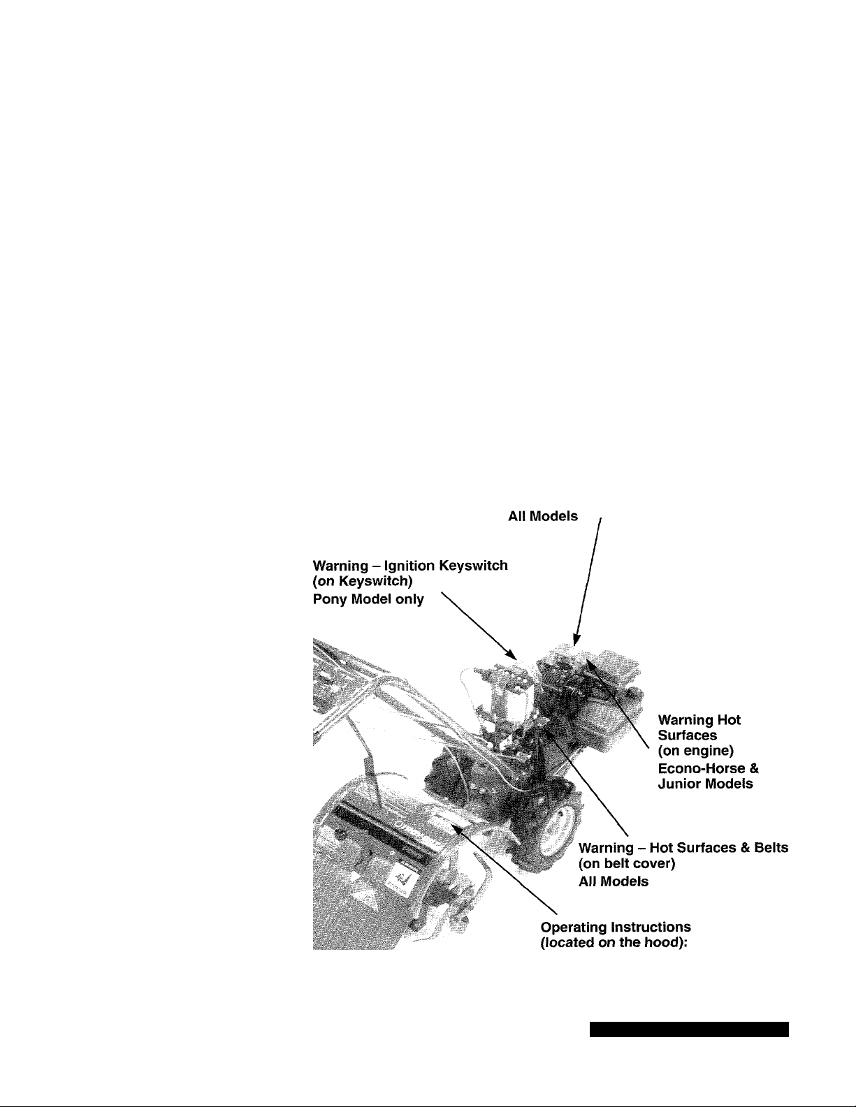
DECALS
If any of the decals below become illegible, damaged, or missing, contact us or your authorized
dealer immediately for a replacement. Use the appropriate part number noted in your Parts Catalog.
Control Panel Decal
(located on upper handlebars);
All Models
Starting Stabilization Decal
(on top of engine or on air cieaner)
Warning - Belt Positions
(on beit cover - not shown)
Econo-Horse Model only
Ail Models
Photo 1-1: Pony Model shown
Page 9
Section 2: Easy Assembly
Please follow the steps in this Section to assemble your ECONO-HORSE™, PONY® or JUNIOR®
Model tiller and prepare it for use. Due to assembly similarities, we show one model in the as
sembly photos to represent the three tiller models. Steps unique to any single model(s) are
noted. These steps will not take long and will assure correct assembly of your new tiller.
We recommend you read this Section all the way through first. Then begin the assembly steps.
STEP1: UNPACKING AND LOOSE PARTS
Your tiller was shipped fully assembled except for the parts shown in Photos 2-1 and 2-2. The small
hardware items are inside a plastic bag within the literature package.
If you ordered an electric start PONY® Model Tiller, you also get a second plastic bag with electric
start parts and hardware - it is near the battery. The battery will be in place on its platform or in its own
carton. These parts are called out later in this section.
___ __ __ ___ __ __ _
WHEEL GEAR CABLE
(Except Junior Model)
MANEUVERING
CLUTCH LEVER
HANDLEBARS
FORWARD CLUTCH ROD
Photo 2-1: Contents of the shipping carton.
ENGINE THROTTLE CABLE
Pony Model shown
The items in the following list are found in your
hardware bag. They are keyed to Photo 2-2.
1. One Handlebar Height Adjustment Handle.
2. One keyed washer.
3. Four plastic tie straps (Junior requires two).
4. Three hairpin cotters.
5. Two 3/8" -16x1" hex head bolts.
6. Two 3/8" flat washers.
7. Two 3/8" -16 nylon insert lock nuts.
8. One Engine Throttle Lever Knob.
9. Four #10 - 32 X 1/2" slotted head screws
(Junior requires two).
10. Four #10 lockwashers (Junior requires two).
11. Four #10 - 32 nuts (Junior requires two).
12. One Wheel Gear Lever knob (Econo-Horse
and Pony).
(See detailed hardware list)
Photo 2-2: Contents of Hardware Package.
Page 10

Compare the parts that you received to those shown in Photos 2-1 and 2-2. If you are missing any
items, please call us at one of the telephone numbers listed on page 3 of this Manual.
If you notice any freight damage, either at the time of delivery or later during assembly, contact the
freight terminal and tell them you will be filing a written claim (do so within 15 days). The terminal will
advise you as to how to proceed. However, if you meet any problems with this procedure, please call
us so we can provide assistance.
Before you attempt to move the tiller off the shipping carton platform, please install the handlebars
(Step 2). With the handlebars installed, you’ll have better leverage and be more easily able to move the
tiller to a level area so you can continue assembly. (Discard all rubber bands securing the handlebars.)
You’ll need the following tools to assemble your tiller;
1. Two 9/16" wrenches. *
2. One medium-size flat blade screwdriver.
3. One open end 3/8" wrench.*
4. Scissors (to trim the plastic ties).
5. One 7/16" wrench (electric models only).*
7. Automotive-type tire pressure gauge.
8. Ruler.
9. Sturdy wood box or block 2-1/2"-3-1/2" high
(Junior Model only).
* You may substitute adjustable wrenches.
6. A piece of wood to tap the knobs securely on
the control levers.
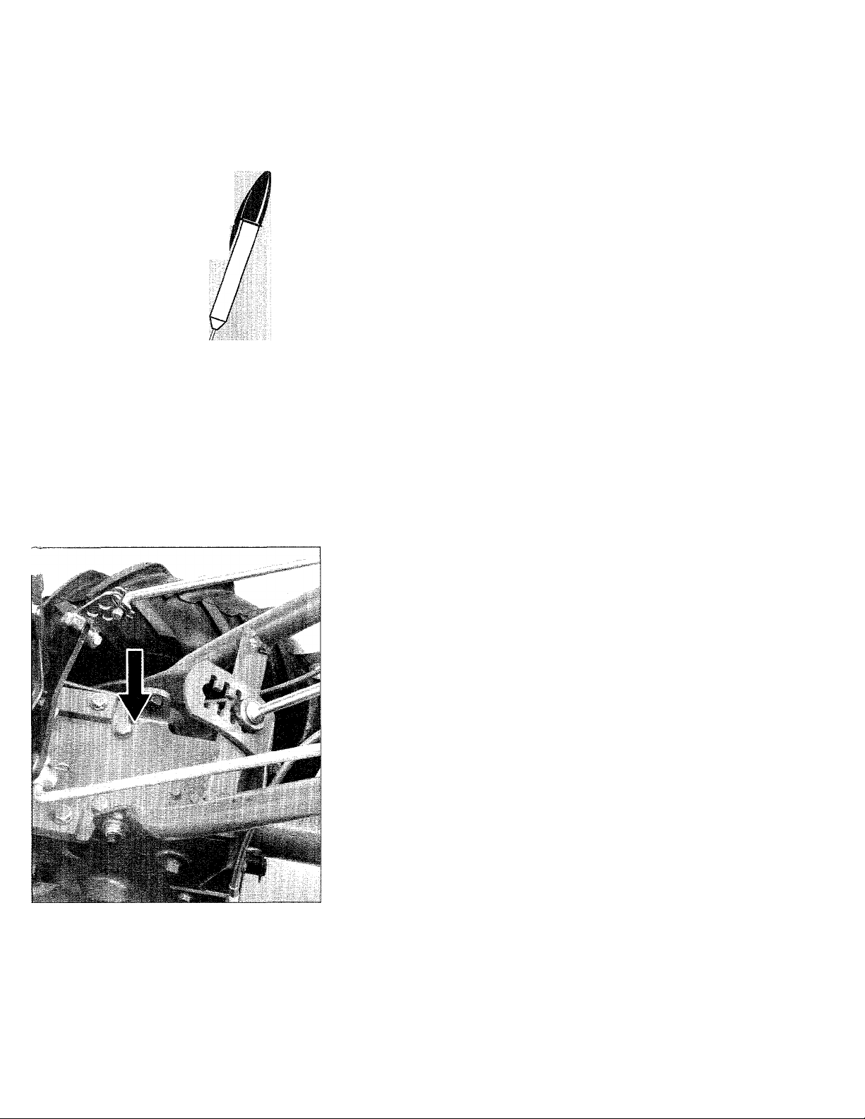
To Remove Tiller From Shipping Platform:
Before moving the tiller off its shipping platform,
you must move the Wheel Gear Lever (on
Econo-Horse and Pony models) to the “DISEN
%
GAGE” position. For shipping purposes, the
Wheel Gear Cable is wrapped around the trans
mission tube, between the engine and the tine
hood. Unwrap the Wheel Gear Cable and move
the Wheel Gear Lever at the end of the cable to
its “DISENGAGE” position as shown in Photo
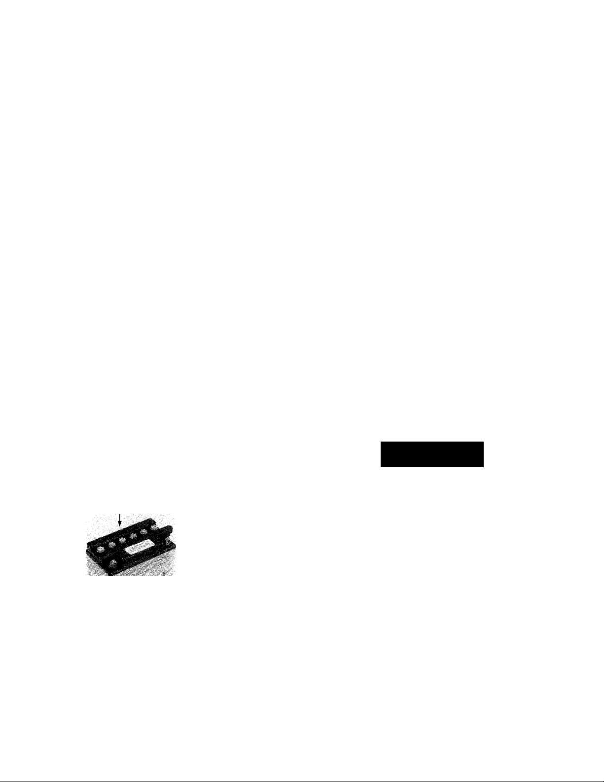
2-3. On the Junior Model, a Wheel Drive Pin
must be removed from the hub of each wheel,
the wheels moved inward as far as possible, and
the Wheel Drive Pins replaced through the wheel
shaft holes and secured with their cotter pins.
Each wheel is then free to turn on the wheel
shaft. See Inset Photo at right.
Photo 2-3: Pull the Wheel Gear Lever back to
“Disengage” position on Econo-Horse and Pony
models. Inset Photo shows Wheel Drive Pins that
r ■i- W.
need to be moved on the Junior Model.
STEP 2: ATTACHING THE HANDLEBARS
1. On electric start models only, remove one of
the bolts and lockwashers that secures the lower
end of the curved height adjustment bracket to
the back of the transmission. Loosen the second
bolt so you can swing the curved height adjust
ment bracket out of the way. See Photo 2-4.
T , s
Mb
Photo 2-4: Swing the Height Adjustment Bracket
down to one side (Electric start models only).
2. Remove the Maneuvering Clutch Lever from
the handlebars. See Photo 2-5.
-
Photo 2-5: Removing the Maneuvering Clutch Lever
from the handlebars. Just slide it out.
Page 11
3. Place the lower end of the handlebars on the
outside of the two mounting tabs on the top of
the transmission. Be sure the handlebar cross
brace (on the lower end of the handlebars) goes
under the curved height adjustment bracket.
4. Secure the lower ends of the handlebar to the
two mounting tabs with a 3/8"-16 x 1" bolt, a 3/8"
flat washer, and a 3/8"-16 nylon insert lock nut.
Use 9/16" wrenches. Both bolt heads should be
inserted from the inner side of the mounting tab.
5. On electric start models, move the curved
height adjustment bracket back in place.
Reinstall the bolt and lockwasher you previously
removed. Tighten both bolts very securely.
6. Move the handlebar up (or downward) to align
the hole in the handlebar cross brace with one of
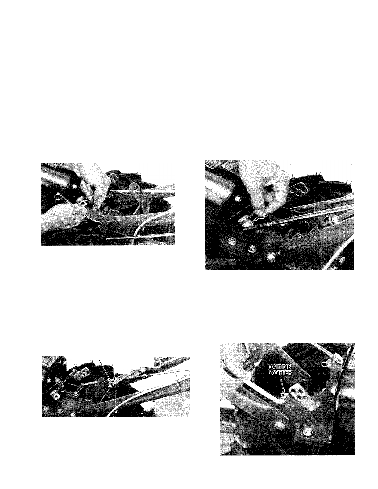
STEP 3: ATTACHING THE
MANEUVERING CLUTCH LEVER
1. Slide the Maneuvering Clutch Lever down
through the hole in the left-hand side of the han
dlebar control panel. Make sure that the
Maneuvering Clutch Lever passes above the
cross brace on the lower end of the handlebar.
2. Turn the Maneuvering Clutch Lever so the
small bend on the lower side points inward.
3. Insert the lower end of the Maneuvering
Clutch Lever into the hole in the pivot as shown
in Photo 2-8. Secure the Maneuvering Clutch
Lever in place by inserting a hairpin cotter down
through the hole in the end of the Maneuvering
Clutch Lever.
Photo 2-6: Attaching the handlebars.
the four slots in the curved height adjustment
bracket. See Photo 2-7. Place the keyed washer
on the Height Adjustment Handle. Screw the
handle into the hole in the handlebar cross
brace. Make sure that both raised keys on the
bottom of the keyed washer fit into one of the
four slots on the bracket. Tighten the Handlebar
Height Adjustment Handle securely. Also tighten
the hardware securing the ends of the handlebar
to the two mounting tabs.
KEYED
WASHER lockwasher
Photo 2-7: Installing the Handlebar Height Ad
justment Handle.
Photo 2-8: Installing Maneuvering Clutch Lever.
STEP 4: CONNECTING THE
FORWARD CLUTCH ROD
1. Turn the Forward Clutch Rod so the small
bend at the lower end points inward.
2. Insert a hairpin cotter down into the inner hole
in the small bend of the Forward Clutch Rod.
7. With the handlebars installed, you can now
easily move the tiller off its shipping platform.
Note: Out in the garden you may need to
readjust handlebar height again for comfort.
See Handlebar Height Adjustment, page 21.
Photo 2-9: Connecting the Forward Clutch Rod.
Page 12
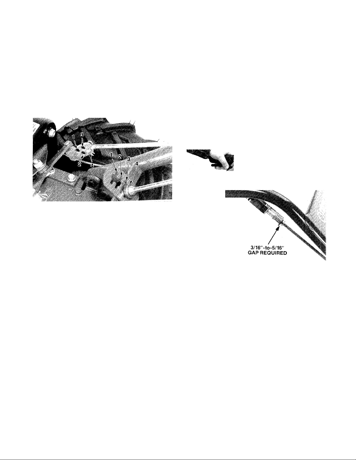
3. Note the four holes in the swivel plate on the
shifting mechanism. The hole that you must in
sert the lower end of the Forward Clutch Rod
into depends upon which handlebar height
setting (on the curved handlebar height ad
justment bracket) you have the handiebars
set at. Refer to Photo 2-10 to determine which
hole in the swivel plate to use. For example: if
you set the handlebar in slot number 1, then the
Forward Clutch Rod must be installed in hole
number 1 of the swivel plate.
c. If the gap is incorrect, reverify that the
Forward Clutch Rod is located in the cor
rect hole in the swivel plate. If it isn’t, move
the lower end of the Forward Clutch Rod
into the correct hole and then check the
measurement gap again.
d. To reset the gap distance properly, you
must make a simple adjustment to the
length of the Forward Clutch Rod. To do
this,disconnect it from the swivel plate,
then rotate it clockwise or counterclock
wise to shorten or lengthen the rod.
Reconnect it and measure the gap again
as shown below in Photo 2-11. Adjust the
length of the rod until the gap is within
3/16" to 5/16".
.-'s»
Photo 2-10: Handlebar Height setting and Forward
Clutch Rod positioning are interrelated. They must
both be set in the same numbered positions.
4. Insert the lower end of the Forward Clutch
Rod into the proper hole in the swivel plate.
Secure it to the swivel plate by inserting a hairpin
cotter through the outer hole in the small bend of
the Forward Clutch Rod.
IMPORTANT
Whenever the handlebar height is changed,
the position of the Forward Clutch Rod must
be changed accordingly. Changing the han
dlebar height changes the tension on the
Forward Clutch Rod. This tension must be
adjusted by relocating the rod in the appro
priate hole in the clutch swivel plate.
To make sure the tension on the Forward
Clutch Rod (once connected) is correct:
a. Stand on the right-hand side of the tiller
and pull the Forward Clutch Lever up and
hold it in place. See Photo 2-11.
b. Check the gap between the “E-ring” and
the lower end of the bracket at the upper
end of the Forward Clutch Rod. Refer to
Photo 2-11.The gap should be 3/16"-to5/16". If you do not have a ruler handy, the
thickness of five pennies is approximately
5/16" thick.
Photo 2-11: Carefully measure the gap between the
Forward Clutch Bracket and the “E-Ring. ”
STEP 5: CHECKING THE TRANSMISSION GEAR OIL LEVEL
Once the handlebars are securely installed on
the tiller, move the tiller to a level area.
We have installed gear oil in the tiller trans
mission here at the Factory. However, you
should make this very important check to be
sure that the gear oil level is still correct.
1. Make sure that your tiller is on a level area.
2. Lower the depth regulator lever to the second
notch to make sure that the transmission is as
level as possible. (See Photo 2-12.). NOTE —
For shipping purposes, the depth regulator lever
might be secured with a plastic tie. If so, before the
depth regulator lever can be lowered, you must lift
the hood flap at the rear of the tiller and cut and re
move the tie.
10
Page 13
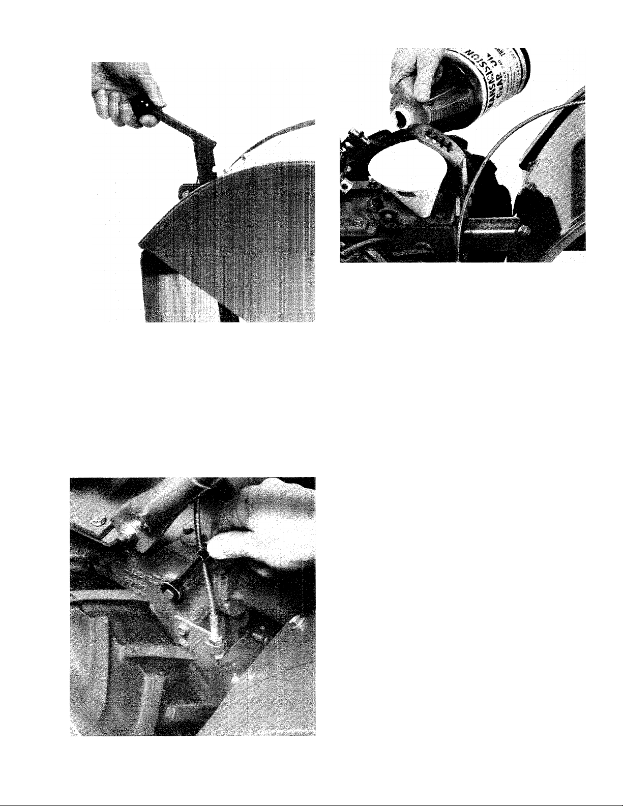
Photo 2-12: Move Depth Rcguldtor Level to second
notch.
3. Use a 3/8" open end wrench to remove the
transmission oil level check plug (on the lefthand side of the transmission). Due to dried
paint on the plug threads, it may require some
force to remove the plug the first time. If the
transmission oil level is correct, oil should start to
flow out of the hole. If oil flows from the hole,
your check is finished; reinstall the plug and
tighten it securely with a 3/8" open end wrench.
Photo 2-13: Removing the transmission Oii Level
Check Plug. When the level is correct, gear oil will
flow from this check hole.
Photo 2-14: Adding gear oil to transmission.
4. If no oil flowed from the transmission oil level
check hole, add SAE 140, SAE 85W-140 or
SAE 80W-90 weight gear oil to bring the oil up
to the correct level. Preferably use API rated GL4 gear oil (GL-5 is permissable for small topoffs). Use this procedure:
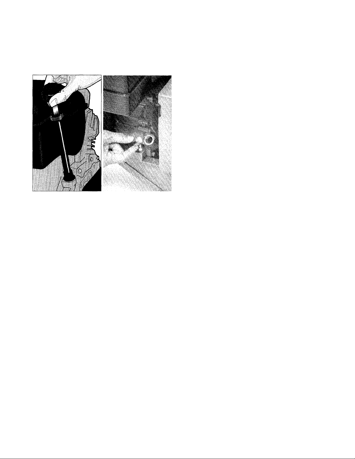
a. Unscrew filler plug from top left-hand side
of transmission. Clean around plug first.
b. Insert a clean funnel into the oil fill hole
and slowly add gear oil until it flows from
the transmission oil check hole.
c. Reinstall the transmission oil check plug.
Tighten securely with the 3/8" wrench.
d. Reinstall the transmission oil fill plug.
Tighten it securely by hand.
STEP 6: ADD MOTOR OIL TO THE TILLER ENGINE
The tiller engine was shipped without
motor oii in it. You must add motor oil before
starting the engine. (See Figure 2-15A and
Photo 2-15B on page 12.) Use quality motor oil
with API classification SF, SG, SH, or SH/CD.
The viscosity depends upon whether you have a
Briggs & Stratton or a Tecumseh engine, and on
temperature. See Pages 48-49 or engine man
ufacturer literature for oil recommendations.
To add motor oil to the engine:
1. Make sure that the tiller is on level ground.
Lower the depth regulator lever to the second
notch (placing the tiller in a level position).
2. Wipe the area around the dipstick or oil fill
tube clean so no debris will fall into the engine.
3. On the Econo-Horse 6HP Tecumseh engine,
unscrew the engine oil dipstick from the fill hole.
See Figure 2-15A. Add oil until the level reaches
“Full” on the dipstick. Do not overfill with oil.
11
Page 14
4. On the Pony 5HP Briggs & Stratton engine
and on the Junior 4HP Tecumseh engine, re
move the filler cap from the oil fill tube at the side
of the engine. See Photo 2-15B. Add oil until it
reaches the very top of the oil fill tube. Replace
the filler cap securely.
5. Snug the base of the throttle lever up against
the bottom of the control panel. Install a lockwasher and a nut on each of the threaded ends
of the screws. Use a 3/8" wrench and a flat tip
screwdriver to tighten both screws.
Photo 2-16: Installing Engine Throttle Lever
Figure 2-15A (left): On 6HP Tecumseh engines, add
oil and check the oil level with the dipstick.
Photo 2-15B (right): On 5HP Briggs & Stratton and
4HP Tecumseh engines, add oil until it reaches the
top of the oil fill tube. Replace the fill cap securely.
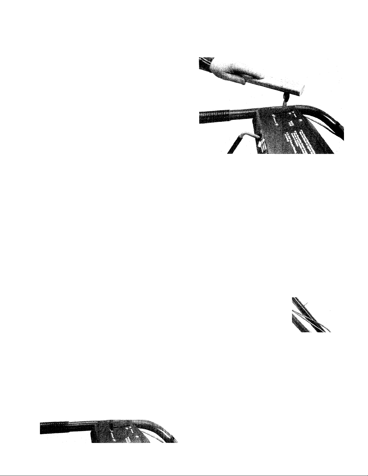
STEP 7: ATTACHING THE ENGINE THROTTLE LEVER TO THE CONTROL PANEL
The engine throttle cable (with lever) is
wrapped around the engine for shipping. Unwrap
it and attach the cable as follows:
1. Locate two #10-32 x 1/2" slotted head
screws, two #10-32 nuts, and two #10 lockwashers in your hardware bag. Keep this hard
ware at hand so you can attach the Engine
Throttle Lever to the control panel.
2. Run the engine throttle cable alongside the
right-hand handlebar.
3. Position the Engine Throttle Lever beneath
the control panel. Insert the lever up through the
slot in the control panel that is marked “ENGINE
THROTTLE.”
4. Insert each of the screws through a “-i-” mark
on the control panel decal. Align the holes in the
Engine Throttle Lever base with the screws and
be sure the screws go through the base.
6. Place the “T-shaped” Engine Throttle Lever
knob on the end of the Engine Throttle Lever.
Use the piece of wood to tap the knob until it
seats firmly on the Engine Throttle Lever.
.. =•; ^ I
Photo 2-17: Install the Engine Throttle Lever Knob.
7. Move the Engine Throttle Lever forward and
backward to check its movement. It should move
smoothly through the full range of its travel.
Please note there is a detent (a catch) at
“SLOW.” This prevents you from unintentionally
shutting off the engine when you are just trying
to slow the engine down. If it is difficult to move
the Engine Throttle Lever away from “STOP”,
loosen both screws and move the lever assem
bly slightly to the left. Tighten both screws and
re-check the Engine Throttle Lever’s movement.
Spend a couple of minutes adjusting this assem
bly until the lever moves smoothly.
12
Page 15
8. Take two of the red plastic ties from the hard
ware bag. Locate them as shown in Photo 2-18.
Space them about two feet apart.
The serrated side of each plastic tie should be
on the inside of the loop when you wrap the tie
around the handlebar and Engine Throttle Lever
cable. Tighten each tie by pulling on the free
end. Snip off any excess with a scissor.
Photo 2-18: Secure Engine Throttle Cable to
Handlebars with two plastic ties.
STEP 8: ATTACHING THE
WHEEL GEAR LEVER TO THE
CONTROL PANEL (Econo-Horse
and Pony Models only)
The Wheel Gear cable is wrapped around the
transmission for shipping purposes. Unwrap the
cable and install it as follows:
1. Locate the last two #10-32 x 1/2" slotted head
screws, #10-32 nuts, and #10 lockwashers.
2. Position the Wheel Gear cable along the side
and up the left handlebar.
3. Position the Wheel Gear Lever beneath the
control panel. Insert the lever up through the slot
in the panel marked “WHEEL GEAR.”
4. Insert both of the screws through a “-h” mark
on the control panel decal. Align the holes in the
Wheel Gear Lever base with the screws and
place the base over the screws.
5. Double check to make sure that the screws go
through the holes in the lever’s base. Install a
lockwasher and nut on each of the screws. Use
a 3/8" wrench and a flat tip screwdriver.
%
Photo 2-19: Installing the Wheel Gear Lever. (EconoHorse and Pony Models only.)
6. Place the Wheel Gear Lever knob on the end
of the Wheel Gear Lever. Use the piece of wood
to tap the knob until it seats on the lever.
Photo 2-20: Installing Wheel Gear Lever Knob.
(Econo-Horse and Pony Models only.) \
7. Use the two remaining plastic ties in the hard
ware bag to secure the Wheel Gear cable to the
left-hand handlebar. Position the ties as shown
in Photo 2-21. Remember that the serrated side
of the tie should be on the inside when you loop
the tie around the handlebar and Wheel Gear
cable. After you’ve tightened the ties by pulling
on the loose ends, snip off any excess.
%
%
%
Photo 2-21: Secure Wheel Gear Cable to Handlebar.
(Econo-Horse and Pony Models.)
STEP 9: ADJUSTING THE AIR
PRESSURE IN THE TIRES
To be sure of a good seal between the tires
and wheels, we’ve inflated your tiller’s tires
above the recommended operating pressure.
Before using your tiller, be sure to evenly de
flate both tires until their pressure is 15 to 20 psi
(pounds per square inch). You can check the air
pressure with an automotive-type tire pressure
gauge.
Be sure that both tires have the same air pres
sure or the tiller will pull to one side when you
are using it.
13
Page 16
If you have a standard start ECONO-HORSE™, PONY®
or JUNIOR® Tiller, it is now completely assembled and
ready to be used.
Please read the rest of this Owner/Operator Manual before you begin to operate your tiller.
You should become very familiar with, and follow all
the safety rules, the tiller operating instructions, and
the engine operating instructions at all times.
If you have an Electric Start PONY® Tiller, you will have
to perform the following steps to assemble the elec
tric starting system on your tiller.
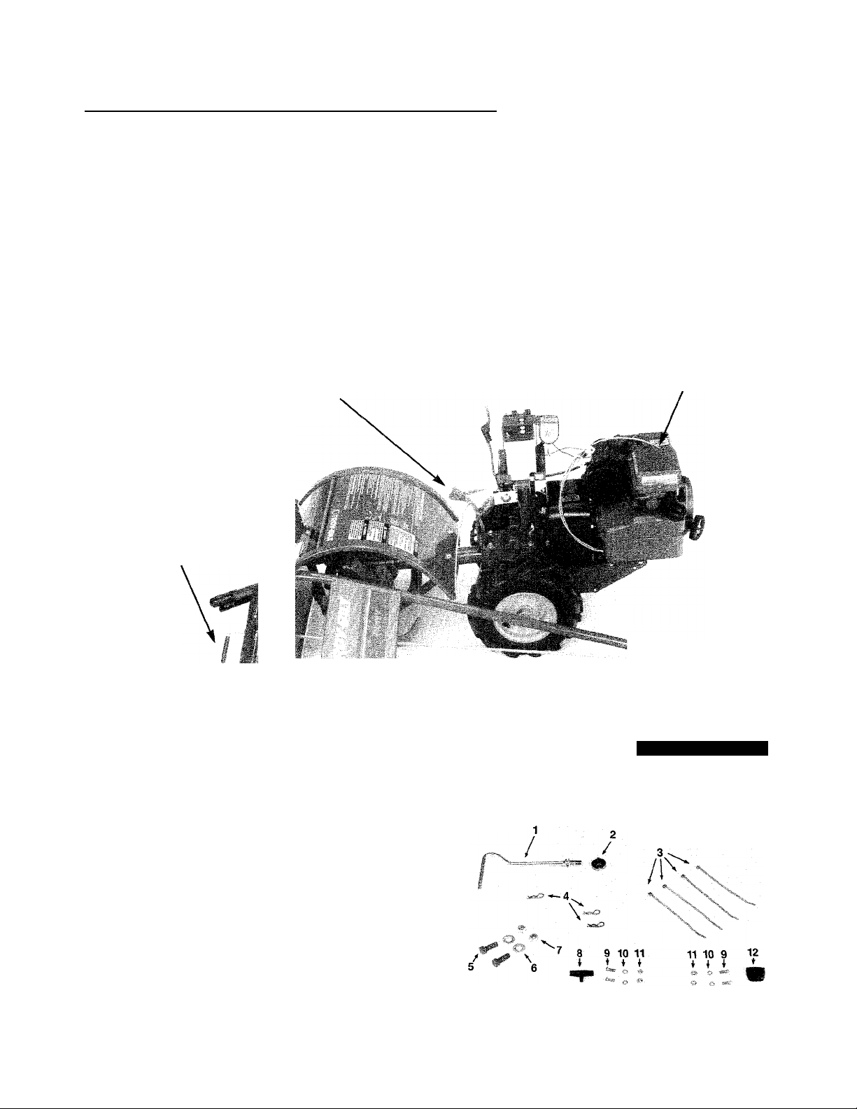
ASSEMBLING THE PONY ELECTRIC START SYSTEM
Compare the parts in your tiller’s electric start
hardware package with the parts shown in Photo
2-22. The parts listed below are keyed to the
hardware items in the photo.
1. Battery (for shipping purposes, it is either se
cured to the battery support bracket or in a pro
tective carton).
2. Vent tube.
3. Screws and nuts (used to attach battery ca
bles to battery).
3
O
STEP 10: BATTERY ACTIVATION AND CHARGING
NOTE
Your battery was shipped to you DRY. You must
have battery electrolyte solution (battery grade
sulfuric acid) added to the battery. You then must
have the battery fully charged before using it on
your tiller.
A DANGER
Electrolyte is a sulfuric acid solution.
Avoid spillage and contact with skin, eyes,
and clothing.
To prevent accidents, wear protective cloth
ing, rubber gloves, and shield eyes with
safety goggles when working near battery.
Neutralize acid spills with baking soda and
water solution. Neutralize empty container
with baking soda and rinse with water.
Photo 2-22: The Electric Start parts.
14
ANTIDOTE: External contact: Flush with water.
Eyes—Flush with water for 15 minutes and get
prompt medical attention.
ANTIDOTE: Internal: Drink large quantities of
water or milk. Follow with milk of magnesia,
beaten eggs, or vegetable oil. Call physician im
mediately.
Page 17

A DANGER
BATTERIES PRODUCE
EXPLOSIVE GASES!
• Keep sparks, flame, and cigarettes away.
• Ventilate area when charging or using bat
tery in an enclosed space.
5. Allow the battery to stand for thirty minutes.
Then check the electrolyte level in each cell. If
needed, add more electrolyte to bring the elec
trolyte level up to the “UPPER LEVEL” line on
the battery. Do not overfill the battery as this
could lead to flooding from the cells when the
battery is being charged.
6. Charge the battery by following the next set of
instructions.
• Make sure venting path of battery is al
ways open once battery is filled with acid.
Adding electrolyte to the battery and charging
the battery can be dangerous. The sulfuric acid
in the electrolyte can severely burn you or blind
you. Also, a battery that is charging gives off
gases that could explode if a spark or flame
should contact the gases.
We strongly recommend that you take your
battery to a TROY-BILT tiller dealer, a reliable
service station, battery store, or farm equipment
store where a trained battery technician can
complete the job safely.
PLEASE DO NOT ATTEMPT TO ACTI
VATE THE BATTERY UNLESS YOU ARE
FULLY EXPERIENCED IN BATTERY SET
UP AND CHARGING PROCEDURES.
To ensure proper activation of your battery, we
suggest you review the following activating and
charging instructions with your battery technician
and make sure that he follows the instructions.
To Activate the Battery:
1. Place the battery on a level area away from any
spark- or flame-producing sources such as a gas
stove, heater, electrical switch, pilot light, (etc.).
2. Remove and discard the short sealing tube (if
installed) on the battery side vent.
3. Remove the six filler caps that are on top of
the battery. Leave the caps off while activating
and charging the battery.
4. Carefully fill each of the six cells in the battery
with electrolyte (battery grade sulfuric acid that
has a specific gravity of 1.265) until the level
reaches the “UPPER LEVEL” line on the battery.
To Charge the Battery
To obtain maximum battery life, charge the
battery by the following method until all cells are
gassing freely. A battery is gassing freely when
the surface of the electrolyte is covered with tiny
bubbles.
A
When checking the battery for gassing, AL
WAYS wear safety goggles and use a flash
light to look down into the cells.
Failure to do so could result in serious per
sonal injury.
Be sure to follow all instructions given by the
manufacturer of the battery charging equipment
that is being used to charge the battery.
1. Hook up the battery charger and charge the
battery approximately three to five hours at one
to two amperes. Turn the battery charger OFF.
2. If the electrolyte level has fallen after charging,
refill the battery with distilled water until the elec
trolyte level reaches the “UPPER LEVEL” line on
the battery.
3. After charging, reinstall the six filler caps on
the battery.
4. Unplug the battery charger from the electrical
outlet (or turn the battery charger OFF). Then
disconnect the cables from the battery posts.
5. Wash any acid spillage off the battery with
water. Then dry the battery.
DANGER
NOTE
• The battery and electrolyte should be between
60° and 80° F for best results.
• Do not add water or any other liquid to activate
the battery.
15
Page 18

STEP 11: INSTALLING THE
BATTERY ON THE TILLER
Photo 2-23: Installing the Battery.
1. Use both hands to carefully place the battery
on the battery mounting bracket. The battery
posts should face to the rear of the tiller. The
positive (+) post should be on the left-hand side
of the tiller and the negative (-) post should be
on the right-hand side of the tiller.
3. Use the two 1/4" -20 x 1 1/4" carriage bolts,
1/4" lockwashers, and 1/4"-20 nuts to secure the
hold-down bracket to the battery mounting
bracket. Insert the bolts from beneath the battery
mounting bracket, up through the battery hold
down bracket, and secure them with the lockwashers and nuts. Use a 7/16-inch wrench to
evenly tighten both nuts. Do not tighten the nuts
so that the tabs on the battery hold-down bracket
become bent.
STEP 12: INSTALLING
THE BATTERY CABLES
1. The Positive battery cable is already con
nected at one end to the solenoid which is
mounted a few inches below the battery on a
post. You are to connect the loose end of the
positive cable to the positive (-r) post on the bat
tery. Use a bolt and nut from the hardware bag.
Use a screwdriver and a 3/8" wrench to tighten
the bolt. See Photo 2-25.
A WARNING
• Be sure that the battery is positioned on
the tiller as explained in Step 1. Hooking the
battery cables to the wrong posts could re
sult in damage to the battery and other
electrical parts.
• Do not touch the positive (-i-) battery post
and any surrounding metal with tools, jew
elry, or other metal objects. Doing so could
cause a short circuit that could result in
electrical burns or an explosion of battery
gases.
2. Place the battery hold-down bracket over the
battery. Center the bolt holes in the lower part of
the hold-down bracket with the bolt holes in the
battery mounting bracket. Make sure that the
Engine Ignition Switch is on the forward side of
the battery.
Photo 2-25: Attach Positive Cabie to Battery.
2. Slide the black rubber boot up the positive
cable and slip it over the positive battery post.
3. The Negative cable is already connected at
one end to one of the mounting bolts securing
the solenoid to the post. This is the grounding
point for the negative cable—connect the loose
end of the nega
tive (-) cable to
the negative bat
ii
...
tery post. Use
the last nut and
last bolt to se
curely attach the
negative battery
cable to the neg
ative (-) battery
post.
Photo 2-24: Securing the Battery in Place.
16
Photo 2-26: Attach the Negative
Battery Cable to
the battery
Page 19

4. Use a 3/8" wrench to check the tightness of
the upper mounting bolt on the starter solenoid.
This bolt secures the Negative Cable to its
ground location. Scrape away any paint between
the cable and the bolt as this would prevent a
proper electrical ground.See Photo 2-27.
Photo 2-27: The Negative Battery Cable must be se
curely grounded to the Upper Mounting Bolt on the
Solenoid.
STEP 14: CONNECT WIRING HAR
NESS TO IGNITION KEYSWITCH
Slide the wiring harness connector over the
prongs on the back of the Ignition Keyswitch,
Your keyswitch has either a 3-prong or 5-prong
design. See Sketch 2-29 or 2-29A.
STEP 13: INSTALLING THE
BATTERY VENT TUBE
1. Push the battery vent tube down into the vent
tube sheath. Attach the upper end of the vent
tube to the side vent on right side of battery.
Awarning
Be sure that the vent tube does not become
kinked, folded, or pinched when you install it.
Improper venting could cause the battery to
explode, resulting in personal injury or prop
erty damage.
Sketch 2-29: Connect the Wiring Harness to the
Ignition Keyswitch. The 5-prong design is shown.
Inset Sketch 2-29A—shows the 3-prong type which
you may have instead of the 5-prong type.
You’re now finished assembling the electric
start PONY® Model tiller.
Before you add gasoline to the gas tank and
begin to operate the tiller, please read the rest of
this Owner/Operator Manual so that you become
familiar with the location of, and the operation of,
the various tiller and engine controls.
Without starting your tiller’s engine, operate
the tiller controls so that you understand what
each one does. After you’ve done this, move the
tiller to a safe, level area to practice starting the
engine and maneuvering the tiller without actu
ally tilling. Make sure that the depth regulator
lever is in the “travel” position (one of the higher
notches) while you’re becoming familiar with
your new tilier.
Take this Manual along for ready reference
while you’re practicing in case you have any
questions about operating your tiller.
Photo 2-28: Installing the Battery Vent Tube.
Awarning
To avoid serious personal injury or damage
to equipment, do not attempt to operate the
tiller or its engine until after you’ve read and
understood all of the Safety, Controls, and
Operating Instructions in this Manual, in the
Engine Owner’s Manual, and in other litera-
ture you may receive.
_____________________
17
Page 20

Section 3:
Tillei’ And Engine Controls
Before attempting to operate your new tiller, become thoroughly familiar with the location of
and function of all the operational controls.
Practice using these controls—with the engine shut off—until you understand the operation
of the controls and feel confident with each one of them.
TILLER CONTROLS
There are four tiller controls you will be using when you operate your tiller. These controls are: the
Wheel Gear Lever (ECONO-HORSE and PONY Models only), the Forward Clutch, the Maneuvering
Clutch, and Depth Regulator Lever. Refer to Photos below for the location of these controls.
/MANEUVERING
CLUTCH LEVER
ENGINE
THROTTLE
LEVER
FORWARD
CLUTCH ‘PADDLES'
DEPTH
REGULATOR ,
LEVER -
HANDLEBAR
HEIGHT
ADJUSTMENT
Photo 3-1: Location of controls on the PONY and
ECONO-HORSE Models. (Pony Model shown.)
Wheel Gear Lever
(Econo-Horse and Pony Models only)
This lever is located on the left-hand side of
the handlebar control panel. It has two positions:
ENGAGE and DISENGAGE (FREE WHEEL).
The ENGAGE position allows power from the
engine to turn the wheels and tines whenever:
a. The Forward Clutch is engaged, OR
b. The Maneuvering Clutch is engaged in either
forward or reverse.
The DISENGAGE (FREE WHEEL) position
should only be used when the engine is not run
ning. Use the DISENGAGE (FREE WHEEL) po
sition ONLY when you are rolling the tiller to an
other location.
BOLO TINES-
WHEEL
DRIVE PIN
AIR CLEANER
^ CHOKE
Photo 3-1 A: Location of controls on the JUNIOR
Model tiller.
A DANGER
NEVER place the Wheel Gear Lever in DIS
ENGAGE (FREE WHEEL) when the engine
is running.
Having the Wheel Gear Lever in DISEN
GAGE (FREE WHEEL) and then engaging
the tines/wheels with either the Forward
Clutch or the Maneuvering Clutch could
allow the tines to propel the tiller rapidly for
ward or backward.
Failure to follow this instruction could result
in personal injury or property damage.
18
Page 21

To operate the Wheel Gear Lever:
1. Roll the tiller a few inches forward or back
ward while you gently move the Wheel Gear
Lever ahead to ENGAGE. Don’t force the lever
into ENGAGE (see Pg 43 for lever adjustment).
2. To place the Wheel Gear Lever in DISEN
GAGE (FREE WHEEL), simply move the lever
rearward. You don’t have to move the tiller when
you move the Wheel Gear Lever into DISEN
GAGE (FREE WHEEL).
To Engage the Wheels in WHEEL DRIVE:
A. Make certain the engine is stopped and the
spark plug wire is disconnected.
B. Raise one wheel off the ground and place a
sturdy block beneath the transmission.
C. Remove the hair pin cotter and pull the Wheel
Drive Pin out.
D. Slide the wheel outward on the shaft and re
place the Wheel Drive Pin through the hole in
the wheel hub AND the hole in the wheel shaft.
Replace the hair pin cotter through the Wheel
Drive Pin, pushing the cotter pin in as far as it
will go. See Photo 3-2A.
E. Repeat these steps with the other wheel.
%
4.;
Photo 3-2: The Wheel Gear Lever in “ENGAGE” po
sition. Econo-Horse and Pony Models only.
Wheel Drive Pins (Junior Model only)
Both wheels on the Junior tiller are held in
place by a Wheel Drive Pin (Photo 3-2A). The
pins are used to engage and disengage drive
power to the wheels. Before starting the engine,
the Wheel Pins must be in the WHEEL DRIVE
position. Do this by inserting the pins through the
holes in the wheel hubs AND the holes in the
wheel shaft. This “locks” the wheels to the wheel
shaft, so they will turn when either the Forward
Clutch or the Maneuvering Clutch is engaged.
To move the tiller when the engine is not run
ning, the wheels must be able to “FREE
WHEEL”. To permit this, insert the Wheel Drive
Pins through the wheel shaft holes only. When
this is done, the pins will keep the wheels on the
wheel shaft, but the wheels will be free to rotate
as they are no longer “locked” to the shaft.
A WARNING
NEVER operate the tiller under engine
power if the wheels are in FREE WHEEL
position(Wheel Pins through wheel shaft
only). In FREE WHEEL, the wheels will not
hold the tiller back and the tines could pro
pel the tiller rapidly, possibly causing loss of
control and serious injury or property dam
age. Always engage the wheels in WHEEL
DRIVE position before starting the engine or
engaging the Forward Clutch or Maneuvering
Clutch.
A WARNING
To avoid personal injury, do not lay the tiller
on its side while adjusting the wheels. This
could cause gasoline to leak from the fuel
tank, resulting in an unsafe condition.
Photo 3-2A: Install Wheel Drive Pin through wheel
hub and shaft for WHEEL DRIVE position.
To Engage the Wheels in FREE WHEEL:
A. Repeat Steps A, B, and C of the previous
“Wheel Drive” engagement instructions.
B. Slide the wheel fully inward on the shaft.
C. Place Wheel Drive Pin through hole in wheel
shaft only, as shown in Photo 3-2B.
D. Replace the hair pin cotter through the Wheel
Drive Pin. Push it in as far as possible.
E. Repeat Steps A through D with the other
wheel. Remove the support block.
Photo 3-2B: Install Wheel Drive Pin through wheel
shaft only for FREE WHEEL position.
19
Page 22

Forward Clutch
This control is the two interconnected “pad
dles” that hang down beneath the control panel.
It is used to engage and disengage both the
wheeis and the tines in forward motion.
To operate the Forward Clutch:
Before engaging the Forward Clutch, first
make sure that the Wheel Gear Lever (EconoHorse and Pony Models only) is in ENGAGE. On
the Junior Model, the Wheel Drive Pins must be
through the holes in the wheel hubs and the
wheel shaft. Then lift up on either or both of the
“paddles” and hold it (or them) against the under
side of the handlebar grips. As long as you hold
the “paddles” in this position, both the wheels
and tines will turn.
To stop forward motion of the tines and wheels
when you have the Forward Clutch engaged,
simply release the “paddles” and allow them to
drop downward. Both the wheels and tines will
stop rotating—the engine will continue to run.
Maneuvering Clutch
This control is located at the rear of the left-
hand side of the control panel. It is the rod hav
ing a 90° bend and a black plastic grip.
The Maneuvering Clutch is used to precisely
maneuver the tiller in either a forward or back
ward direction. Pulling the Maneuvering Clutch
out (for REVERSE) or pushing the Maneuvering
Clutch in (for FORWARD) engages both the
wheels and tines.
If you want to precision till near an obstacle,
release the Forward Clutch “paddles” and push
in the Maneuvering Clutch Lever. When you
want to stop tilling with the Maneuvering Clutch
Lever, release it—it will automatically return to
NEUTRAL.
If you want to move the tiller forward for a
short distance or in close quarters, release the
Forward Clutch paddles, lift up on the handle
bars until the tines clear the ground. Then push
the Maneuvering Clutch in. To stop forward mo
tion, release the Maneuvering Clutch Lever.
The only way you can make the tiller move in
reverse is by using the Maneuvering Clutch
Lever. Lift up on the handlebars until the tines
clear the ground and then pull the Maneuvering
Clutch Lever out. The tines and wheels will both
move in reverse direction for as long as you hold
the Maneuvering Clutch Lever in REVERSE. To
stop reverse motion of the tines and wheels, sim
ply release the Maneuvering Clutch Lever.
Photo 3-3: The Forward Clutch.
A WARNING
NEVER move the Maneuvering Clutch into
either FORWARD or REVERSE unless the
Wheel Gear Lever on Econo-Horse and
Pony Models is in ENGAGE. On Junior
Models, the Wheel Drive Pins must be in
WHEEL DRIVE POSITION.
Placing the Maneuvering Clutch in either
FORWARD or REVERSE when the wheels
are not engaged could allow the tines to
rapidly propel the tiller forward or backward.
Failure to follow this warning could result in
personal injury or property damage.
20
i
A
• When moving the tiller in reverse, always
look behind you to check for, and avoid,
obstacles.
• Never attempt to till in reverse.
Failure to follow these instructions could re
sult in personal injury.
WARNING
N
I
Photo 3-4: The Maneuvering Clutch.
Page 23

Depth Regulator
The lever at the rear of the tine hood is the
Depth Regulator Lever. Pulling back on this lever
and moving it either up or down allows you to
control the depth of tine penetration in the soil.
When you move the Depth Regulator Lever all
the way down (engaging the highest notch on
the depth regulator), you put the tiller in the
“travel” position. This position allows you to
move the tiller without damage to your lawn by
allowing the tines to clear the ground by approxi
mately 1-1/2 inches.
When you move the Depth Regulator Lever all
the way up (engaging the lowest notch on the
depth regulator), you get the deepest tilling
depth (approximately six to eight inches, de
pending on soil conditions).
You should begin tilling at one of the shal
lower Depth Regulator Lever settings and
gradually increase the tilling depth and not
attempt to till too deeply too soon.
Awarning
Handlebar Height Adjustment
To adjust the handlebar height:
1. Loosen both bolts at the bottom of the handlebar.
2. Loosen the handlebar height adjustment han
dle until the keys on the bottom of the keyed
washer can clear the slots in the curved handle
bar height adjustment bracket.
3. Move the handlebar up or down to the height
you desire. Align the hole in the handlebar cross
brace with one of the four slots In the curved
handlebar height adjustment bracket.
4. Align the keys on the bottom of the keyed
washer with the slot in the curved handlebar
height adjustment bracket. Screw the handlebar
height adjustment handle into the hole in the
handlebar crossbrace. Tighten it securely.
5. Retighten both bolts at bottom of handlebar.
6. Readjust the Forward Clutch mechanism by
performing the following steps:
a. Remove the inner hairpin cotter from the
lower end of the Forward Clutch Rod.
To avoid injury, always place the Depth
Regulator Lever in the TRAVEL position be
fore starting the engine. This position pre
vents the tines from touching the ground
until you are ready to begin tilling.
...' i.i
t '.P
à-î''' f■ if:
.f'r’-'r'-' ■ ■; '
■
Photo 3-6: Adjusting the Handlebar height.
Awarning
• When you change the handlebar height,
you MUST readjust the Forward Clutch
mechanism.
• When adjusting or checking Forward
Clutch mechanism, shut engine off, discon
nect spark plug wire and prevent it from
touching the spark plug.
Photo 3-5: The Depth Regulator Lever.
Failure to do this could allow the Forward
Clutch mechanism to operate improperly,
which could result in personal injury or
property damage.
21
Page 24

b. Use Photo 3-7 to determine which hole in
the swivel plate you should insert the lower
end of the Forward Clutch Rod into. For exam
ple, if you have the handlebar height setting at
position number 1 (on the curved handlebar
height adjustment bracket) insert the lower
end of the Forward Clutch rod into hole num
ber 1 on the swivel plate.
Photo 3-7: Handlebar Height setting and Forward
Clutch positioning.
c. Insert the lower end of the Forward Clutch
Rod into the proper hole in the swivel plate.
Secure it in place by reinstalling the hairpin
cotter in the inner hole in the Forward Clutch
Rod.
d. To make sure that the amount of tension
the Forward Clutch Lever applies is correct;
(1) . Stand on the right-hand side of the tiller.
Pull the Forward Clutch Lever up and hold it
in place.
(2) . Check the gap between the E-Ring and
the lower end of the bracket on the Forward
Clutch Lever. The gap should be 3/16" to
5/16". If you do not have a ruler handy, five
pennies are approximately 5/16“ thick.
Refer to Photo 3-8.
e. If you are unable to get the 3/16" to 5/16"
gap, you’ll have to readjust the Forward Clutch
Rod as follows:
(1). Pull the Forward Clutch Lever up and
hold it in place.
Photo 3-8: Measuring the gap between the Forward
Clutch Bracket and the E-Ring.
If the gap is greater than 5/16". you’ll
have to release the Forward Clutch Lever,
remove the hairpin cotter from the inner
hole in the lower end of the Forward Clutch
Rod, move the Forward Clutch Rod away
from the swivel plate, and turn the rod coun
terclockwise (as viewed from the front of the
tiller) to decrease the gap.
If the gap is less than 3/16". you’ll have to
release the Forward Clutch Lever, remove
the hairpin cotter from the inner hole in the
lower end of the Forward Clutch Rod, move
the Forward Clutch Rod away from the
swivel plate, and turn the rod clockwise (as
viewed from the front of the tiller) to in
crease the gap.
f. After getting the correct gap, make sure that
you return the Forward Clutch Rod to the right
hole in the swivel plate, then reinstall the hair
pin cotter in the inner hole in the lower end of
the Forward Clutch Rod.
ENGINE CONTROLS
Please read the following information about engine controls and operation. You should also read the
Engine Owner’s Manual that you received in your literature package.
Starting Your Engine—Recoil Start and
Electric Start Models
1. Check to make sure that the spark plug wire is
securely attached to the spark plug.
2. Make sure that the Wheel Gear Lever is in
“ENGAGE” on Econo-Horse and Pony Models.
22
On Junior Models, there is no Wheel Gear Lever,
but the Wheel Drive Pins should be through the
wheel hubs and wheel shaft holes in “ENGAGE.”
3. Move the Depth Regulator Lever all the way
DOWN so the tines are in the “travel” position
(they should clear the ground by about V'^").
Page 25

4. Move the carburetor choke lever to “FULL
CHOKE” position on the 4HP Tecumseh engine
or the 5HP Briggs & Stratton engine (in the direc
tion of the arrow on 4HP Tecumseh engines; to
ward “Choke” on 5HP Briggs & Stratton en
gines). On the 6HP Tecumseh engine, push in
the fuel primer button once or twice (providing
the engine is cold; otherwise do not prime engine).
See Figure 3-9, Photo 3-10 or Photo 3-11.
Photo 3-13: Use
starter rope to start
engine.
Figure 3-9:
Econo-Horse
Model- fuel
primer button
on the 6HP
Tecumseh
OHV engine.
Photo 3-10:
Pony Modelchoke lever de
sign on the 5HP
Briggs engine.
Photo 3-11:
Junior Modelchoke lever
design on the
4HP Tecumseh
engine.
5. Move the Engine Throttle Lever (on the right-
hand side of the control panel) to “START.”
7. For Electric Start models, turn the Engine
Ignition Switch to “START.” Don’t keep the switch
in START for longer than ten seconds. You may
have to try this several times before the engine
starts — allow the engine to come to a complete
stop before you turn the switch to START again.
When the engine starts, release the key; it will
automatically return to “RUN.”
8. After the engine is running, gradually move
the Carburetor Choke Lever to NO CHOKE on
the Junior 4HP Tecumseh engine or the Pony
5HP Briggs & Stratton engine. There is no choke
lever on the Econo-Horse 6HP Tecumseh engine.
Starting the Electric Start Engine with the Recoil Starter Rope
If necessary, the electric start engine can be
started with the recoil starter rope. Before doing
so, be sure to follow the procedure below.
1. If the battery is in good condition (not “dead”
or damaged), keep it on the tiller. This lets it
recharge during engine operation. However, be
fore starting the engine with the recoil starter
rope, make sure the battery is filled to the
UPPER LEVEL line with electrolyte.
2. If the battery is “dead” or damaged, remove it
from the tiller and have it tested by a qualified
technician. Before using the starter rope to start
the engine, disconnect the positive battery cable
from the starter solenoid. Reinstall it after replac
ing the battery.
IMPORTANT-When starting the engine with the
starter rope, turn the Ignition Key Switch to RUN.
Also move the Engine Throttle Lever to START.
Photo 3-12: Engine Throttle Lever.
6. For Standard Start models, grasp the starter
rope handle with one hand. Brace the tiller by
placing your free hand on the gas tank. Puli the
starter rope slowly until you feel resistance. Then
pull the starter rope out rapidly...but let it rewind
slowly. You may have to repeat this procedure
several times until the engine starts. When you
pull the rope outward, be sure that nothing is be
hind you.
Stopping the Engine
To stop the wheels/tines at any time, simply
release the Forward Clutch “paddles” or the
Maneuvering Clutch Lever (whichever one you
have engaged).
1. To stop the engine on a Standard Start model,
move the Engine Throttle Lever to STOP.
2. To stop the engine on an Electric Start model,
you can either move the Ignition Key Switch to
OFF or you can move the Engine Throttle Lever
to STOP.
23
Page 26

Section 4:
Operation Of Tiller
Please be sure that you’ve read, fully understand, and always follow the Safety Instructions
(Section 1 ) and the Tiiler and Engine operating instructions (Sections 3 and 4) before you at
tempt to operate your tiiier.
Take a few minutes to famiiiarize yourself with the basic operation of your tiiier before you
use it in the garden. Locate a ciear, ievel area and practice engaging the tiiier controls and run
ning the tiiier back and forth. When you do this, make sure that the tines are in the “travei” po
sition (Depth Reguiator Lever pushed aii the way down).
Only after you’ve become completely familiar with your tiiier shouid you begin using it in
your garden.
MANEUVERING
CLUTCH
___ __________ __________________________________________
ECONO-HORSE and
PONY MODEL Controls
WHEEL
_____
DEPTH
REGULATOR
LEVER
I
IGNITION
KEYSWITCH
HANDLEBAR
HEIGHT
ADJUSTMENT
(Pony only)
CHOKE
LEVER
\
RECOIL
STARTER
Photo 4-1: Operating your TROY-BILT Rototiller is easy and so rewarding. (Pony Model shown.)
24
Page 27

BEFORE STARTING, ALWAYS:
1. Check the engine oil level; add oil as neces
sary to bring the level up to the FULL mark on
the dipstick or to the point of overflowing if your
engine has an oil fill tube.
2. Make sure the engine air cleaner element is
clean and the air cleaner assembly is tight.
3. Be sure the gas tank has clean, fresh gasoline.
The gas tank cap must be screwed on tightly.
4. Check the spark plug wire; make sure that it is
securely attached to the spark plug.
5. Put the Wheel Gear Lever (on Econo-Horse
and Pony Models) in ENGAGE. On Junior tillers,
the Wheel Drive Pins must be ENGAGED
through the wheel hubs and the wheel shaft.
TO BEGIN TILLING:
1. Make sure that the Wheel Gear Lever is in
ENGAGE on Econo-Horse and Pony Models. On
the Junior Model, the Wheel Drive Pins have to
be engaged.
2. Move the Depth Regulator Lever to the de
sired position.
When practicing with your tiller or when mov
ing the tiller to or from the garden, keep the tines
in the “travel” position.
When tilling, you must move the Depth
Regulator Lever to the desired setting, increase
the engine speed, and then begin tilling.
3. Start the engine and allow it to warm up be
fore increasing the engine speed.
4. For forward motion of the wheels/tines, pull
the Forward Clutch “paddles” up and hold them
up against the handlebars.
If you want to go forward in close quarters,
push the Maneuvering Clutch Lever in. The
tines/wheels rotate while you hold the lever in.
5. For REVERSE motion of the wheels/tines, lift
the rear of the tiller up until its tines clear the
ground and then pull the Maneuvering Clutch
Lever out. Hold the Maneuvering Clutch Lever
out for as long as you need to move in reverse.
To stop reverse motion, let go of the
Maneuvering Clutch Lever. It will automatically
return to NEUTRAL.
Photo 4-2: When you reach the end of a row, slow
the engine down and lift up on the handlebars to
raise the tines from the soil.
Photo 4-3: Use the wheels as a pivot point to balance
the engine and tines. Push the handlebars sideways
to move the tiller in the direction of the turn, and con
tinue up the next row.
TURNING AROUND
Turning your tiller around is fairly easy. You
should practice this maneuver before you take
your tiller into the garden for the first time. See
Photos 4-2 and 4-3.
The key to turning around is remembering that
the balance point of your tiller is the wheels.
When ready to turn around, lift up on the handle
bars to find where the engine and tines are bal
anced. Then push sideways on the handlebar to
move the tiller in the direction of the turn.
STOPPING THE TILLER AND ENGINE
1. To stop the wheels/tines, release the
Forward Clutch “paddles” or release the
Maneuvering Clutch Lever (whichever control
you have engaged).
2. If you want to stop the engine, move the
Engine Throttle Lever to STOP. If you have an
electric start model, you could also turn the
Engine Ignition Switch to OFF.
25
Page 28

CHANGING SPEEDS (Econo-Horse Model tiller only)
The ECONO-HORSE™ tiller has dual speeds
for the wheels and tines. Changing the speed
range is just a matter of moving the forward drive
belt from one set of grooves in the engine-driven
pulley and the transmission pulley to the other
set of pulley grooves.
Use the LOW speed belt range for jobs which
need more power such as tilling sod and un
worked soil; or for tilling under cover crops or ex
tremely heavy weeds. Your ECONO-HORSE
tiller is shipped to you with the belt in the LOW
range. Keep the belt in this range while you are
familiarizing yourself with the operation of the
tiller. After you’ve gained experience with the
tiller, then you can experiment with the HIGH
speed belt range.
Use the HIGH speed belt range for situations
like shallow cultivation, final seedbed prepara
tion, or for power composting heavy leaves,
straw, hay, mulch, or composted material.
However, if the soil you are tilling this material
into is very hard, you may have to return to the
LOW speed belt range for better results.
There is a decal on the top of the belt cover that
shows the belt positions for the two speeds.
To change from LOW Speed to HIGH Speed:
1. Place the Wheel Gear Lever in DISENGAGE
(FREEWHEEL).
2. Use a 1/2" wrench to remove the two nuts that
secure the belt cover to the tiller.
3. From underneath the tiller, work the forward
drive belt into the center groove in the transmis
sion pulley.
4. Push up on the forward drive belt to get slack
where the belt goes around the engine-driven
pulley.
5. Work the belt into the forward groove on the
engine-driven pulley.
ik
Photo 4-5: Removing Belt Cover.
REVERSE ENGI' ■ ■ IHIIII Nil
-DRIVEN PULL
REVERSE
PULLEY
■ A..
ADJUSTABLE
LINK
(Underneath)\.^\
FORWARD
DRIVE B^UT
ENGINE
^ DRIVE
'V
.ADJUSTABLE
PULLEY
' FOg^EQ
Photo 4-4: Overview of Belts and Pulleys.
A WARNING
Before changing belt speeds, stop the en
gine, allow the engine to cool, disconnect
the spark plug wire and prevent it from
touching the spark plug, and remove the
Ignition Switch key.
Failure to follow these instructions could re
sult in personal injury or property damage.
LINK
TRANSMISSION I
PULLEY
Photo 4-6: Moving Forward Drive Belt into High
Speed Groove of Transmission Pulley.
’ A...
FORWARD 'A
DRIVE
ENGINE DRIVEN
PULLEY '
Photo 4-7: Moving Forward Drive Belt into High
Speed Position on Engine-Driven Pulley.
------------
— ,
^ 1
llmm
a X ^
1
■■
i
f "
26
Page 29

NOTE
If the belt only goes part-way into the for
ward groove of the engine-driven pulley, pull
on the start rope to turn the engine-driven
pulley to force the belt Into the groove.
6. Reinstall the belt cover. Use the 1/2" wrench
to securely tighten the nuts.
To change from HIGH speed to LOW speed:
A WARNING
Before changing belt speeds, stop the en
gine, allow the engine to cool, disconnect
the spark plug wire and prevent it from
touching the spark plug, and remove the
Ignition Switch key.
Failure to follow these instructions could re
sult in personal Injury or property damage.
1. Move the Wheel Gear Lever to DISENGAGE
(FREEWHEEL) .
2. Remove the belt cover by removing the nuts
on the back of the cover with a 1/2" wrench. See
Photo 4-5.
3. Move the forward drive belt into the rear
groove on the engine-driven pulley.
5. Reinstall the belt cover. Use the 1/2" wrench
to securely tighten the nuts.
Photo 4-8: Moving Forward Drive Belt into Low
Speed Position on Engine-Driven Pulley.
NOTE
If the forward drive belt will not slip all the
way into the rear groove on the enginedriven pulley, pull the recoil starter rope
while forcing the belt to the rear.
4. From underneath the tiller, work the forward
drive belt from the center groove on the trans
mission pulley to the rear groove.
TILLING IN THE GARDEN
Guiding Your Tiller
While tilling, relax and let the wheels pull the
tiller along while the tines do the digging. Walk
alongside the tiller on the side that is not yet fin
ished (to avoid making footprints in the just-tilled
soil) and lightly, but securely grip the handlebar
with one hand.
Please do not push down on the handlebars in
an attempt to force the tiller to dig deeper. Do
ing so takes the weight off the wheels, reduces
traction, and causes the tines to attempt to pro
pel the tiller instead of just digging. This can
cause the tiller to skip rapidly across the garden.
Sometimes slight downward pressure on the
handlebars will help get through a particularly
tough section of sod or unbroken ground, but in
most cases this won’t be necessary at all.
Photo 4-9: Moving Forward Drive Belt into Low
Speed Position on the Transmission Pulley.
Tilling Depths
When you start to till in the garden, remember
to take it easy. Don’t try to take too deep a cut in
the first pass through sod or hard ground that
has not been tilled for years.
It’s almost impossible to get down four or five
inches on the first pass through untilled soil. In
very hard, dry soil, you should start tilling at a
very shallow depth regulator setting, only an inch
or two deep for the first time. In each succeeding
pass, you can go down a few more inches, grad
ually working down to the depth you want (water
ing your garden a few days prior to tilling will
make the going much easier). At any time, if you
have difficulty getting down really deep, let the
newly worked soil set for a day or two. When you
return to it, the tilling will be easier.
27
Page 30

It is best not to work the soil when it is too
soggy or wet. Doing so will make too many
clumps that won’t break up very easily. If time
will permit, always wait a day or so after heavy
rains for the ground to dry.
In most soils, it’s best to start out at the third
or fourth notch of the depth regulator to break
through the upper inch or two of soil. The fastest
method is to till as deep as you can without mak
ing the tiller jump when it hits rocks, etc., but you
should wait until you are very familiar with the
tiller’s operation before you use that procedure.
When you are cultivating your garden, the
tines should be adjusted to till to a depth of just
1-1/2" to 2" so they won’t injure your plants’
roots, which grow close to the surface. If you no
tice the tines are digging too deeply (even when
in the highest notch), then you may have to lift
up on the handlebars slightly. Also use the high
speed belt range (Econo-Horse Model only)
when cultivating, as the faster wheel and tine
speeds prevent the tiller from digging too deeply.
■ «3-
g. ‘"jE*
f.
?*.>■... --
Sketch 4-12. Again, overlap each pass to really
pulverize the entire garden area. (In very hard
ground, it might take three or four passes before
you make much headway.)
4
■H
Sketch 4-12: Tilling pattern for unbroken ground.
If your garden is not wide enough to till length
wise and then crosswise, then you should first
overlap by one-half a tiller width, followed by
successive passes at one-quarter tiller width.
This overlapping method will assure you of thor
oughly breaking up the ground—See Sketch 4-13.
—HI-- --nr-Tr"|- _______
'■ msir - ■iri -
....
..........
....
- .'V' ~ '
Photo 4-10: Cultivating.
Tilling Patterns
When preparing a seedbed, go over the same
path twice in the first row, then overlap one-half a
tiller width on the succeeding passes—see
Sketch 4-11. After going up and down the rows
in one direction, make a second pass at a right
angle across your earlier passes—refer to
Sketch 4-11: This is the tilling pattern recommended
for previously worked soil. Overlap each row one-half
a tiller width.
Sketch 4-13: Tilling pattern for narrow strips.
If you plan your garden carefully, you can
allow enough room between rows to cultivate, as
shown in Sketch 4-14. The Econo-Horse has a
tilling width of 18" (the Pony 16", and the Junior
14"), so leave that much distance between the
rows, plus enough extra plant growing room
above ground. Remember some crops take lots
of room-like beans, tomatoes, and peas.
Sketch 4-14: Cultivate between plants to uproot un
wanted weeds.
28
Page 31

Choosing Wheel and Tine Speeds
With a little experimenting, you can soon find
the proper tilling depth, engine throttle setting,
and wheel and tine speeds that are just right for
the piece of soil on which you are working. What
this means is:
1. You advance the throttle lever on the handle
bars to keep the engine running at a sufficient
power level to do the job. Don’t run your engine
at full throttle all of the time. Instead, try to judge
when the engine is providing the proper amount
of power—not too little, but not too much.
Matching engine power to the work is easier on
the engine and on the tiller. The sound of your
engine operating will be your best guide.
2. You have the depth regulator set in a notch
which is not so deep that it causes the engine to
labor or the tiller to jump.
3. You have the tines turning over fast enough to
really break up the soil with a minimum number
of passes. Faster engine and wheel speeds may
be desirable to break up the last bits of soil or
vegetation when you are making final passes, or
when you are cultivating.
By the way, try to give your engine a “rest” pe
riod during tilling operations by every so often let
ting it run at low idle for a minute or two— without
any load on it. This practice of giving your engine
a break while you pick up rocks, prepare to start a
new row, or when just pausing for a moment will
improve fuel economy and add years to the life of
your engine.
When your tiller is working properly, you can
hear that the engine is not laboring very hard
and see that the tines are breaking up the soil
into small, thoroughly tilled bits.
Remember that the wheels have two func
tions. First they power the tiller in forward or in
reverse. Also, they turn much slower than the
tines, thus holding the tiller back while the tines
dig. Because the separately geared tines revolve
much faster than the wheels, they can easily
chop up, shred and bury organic material. The
tine hood aids in this process as sod, soil and
vegetation are thrown up against it by the revolv
ing tines, where it is trapped momentarily before
being further broken up and put back in the gar
den.
Avoid Making Footprints
When making final tilling or cultivating passes,
always try to walk alongside the tiller on the side
that is not yet finished. If the ground has been
well prepared, you can easily walk alongside
while guiding your tiller with one hand.
Eliminating footprints contributes much more
than just good appearance to your garden. It
aids in preventing soil erosion and avoids “plant
ing” unwanted weed seeds right back in your
newly tilled ground. It also leaves your soil nice
and loose, so that vegetable roots can penetrate
it easily.
'1
/- ,»?-b • * 7 ‘
Ш
Clearing Debris from the Tine Area
Your Bolo Tines have a self-cleaning action
which just about eliminates most tangling in the
tines. But occasionally, dried out grass, stringy
stalks, or tough vines may become tangled. If
this happens, lift the tines out of the soil and run
your tiller in reverse for a few feet. This reverses
the direction of the tines and should unwind a
good deal of debris.
It isn’t necessary to remove all the residue, but
don’t let it build up to a point where it chokes off
the action of the tines. If reversing the tiller
doesn’t work, then STOP the machine and en
gine and remove the tangled material by hand. A
small pocket knife or linoleum knife will help you
cut away the material.
A
Before unclogging the tines, stop the en
gine, disconnect the spark plug wire and
keep it from touching the spark plug, re
move the Engine Ignition key and allow the
engine and muffler to cool.
Failure to follow these instructions could re
sult in personal injury or property damage.
WARNING
Photo 4-15: Try to avoid leaving footprints.
29
Page 32

Normally, you can avoid most tangling prob
lems by setting the depth regulator deep enough
to get maximum “chopping” action as the tines
chop the material against the ground, and by till
ing under crop residues or cover crops while
they are still green, moist and tender.
Also, you might try swaying the handlebars
from side to side (about 6" to 12") while continu
ing to power compost. This “fishtailing” action
often clears the debris out of the tines.
Power Composting
It is essential that a garden be fed something
if it is to be bountiful year after year in the same
location. You must replenish the plant nutrients—
primarily nitrogen, phosphorous and potas
sium— that you took away from the soil in the
form of harvested vegetables and fruits. The first
place to begin is with crop residues, which in
clude leftover leaves, vines, stems and roots.
Power compost these crop residues directly
into your garden soil as soon as they finish bear
ing. The sooner this is done, the better. Tender
green matter not only tills in easier, but provides
that much more good food for the earthworms
and other beneficial forms of soil life.
Standing cornstalks of reasonable height can
be power composted. Pushing over (but not up
rooting) tall cornstalks will often make it easier
for your tiller to chop up the stalks. Keep the
tines clear of excessive tangling by “fishtailing” or
frequently using Reverse. Make several passes,
then return a few days later to finish off any re
maining stubble.
"• * k,»
After all the power composting has been done,
you should plant a “green manure” cover crop to
protect your soil during the off-season. Green
manures are also called “cover crops” or “catch
crops”. You simply grow a crop of clover, alfalfa,
buckwheat, peas, beans, rye grass, grain, or
kale and then later till it into the soil, thus adding
far more nutrients than you have taken out.
Using Reverse To Help Turn
Around in Tight Areas
Using your tiller near obstacles like fences,
stone walls, sheds or trees needn’t be a problem
if you use Reverse to help you maneuver the
tiller around and away from the obstacles. For
example, turning around at the end of a row in
the garden that’s very near a fence is easy.
When at the end of a row, you can go right up
near the obstacle, then engage the tiller in
Reverse while holding the handlebars up and
turning the tiller at the same time. Alternating
briefly between going Forward and then in
Reverse will let you complete your turn in a very
small area.
n
■ v-vi- , *
■ Vlmm'v'
/^
p',:
>'■. '-'''¿'A.’'' i. J J
/
Photo 4-16: Tilling under cornstalks.
After ail the crop residues have been tilled
under, add more organic matter such as leaves,
grass clippings and even kitchen scraps. This or
ganic matter will decompose and add even more
important nutrients to the soil to help plants
thrive next Spring.
30
Photo 4-17: To turn around in cramped quarters, move
close to obstacle, then put the tiller in Reverse while
lifting up on the handlebars (to raise the tines out of
the soil) and turning the tiller.
Tilling Near Obstacles Requires Caution
Always be sure to avoid coming too close to
any obstacles (fences, rock walls, posts, build
ings, etc.) that could be damaged by your tiller,
or that could cause damage to your tiller.
Whenever possible, stay away from objects such
as this. Tilling another few inches closer to an
obstacle just isn’t worth the property damage
that could occur unexpectedly.
AVOID AREAS THAT MAY HAVE UNDER
GROUND CABLES, WIRES OR GAS LINES!
Page 33

Before you do any tilling with your tiller, please
find out if there are any cables, electric lines or
gas lines that might have been installed under
ground by a local utility company or by a previ
ous owner of your property. If there are any lines,
avoid tilling near them. This is an IMPORTANT
SAFETY PRECAUTION that should be investi
gated fully until you know that you’re tilling in a
safe area.
A WARNING
BEFORE TILLING, CONTACT YOUR
TELEPHONE OR UTILITY COMPANY IF
UNDERGROUND EQUIPMENT OR LINES
ARE USED IN YOUR AREA. Their repre
sentative will be glad to answer your ques
tions and tell you if any of their equipment
or lines are buried underground on your
property.
Tilling Up and Down Slopes
If you must garden on a moderate slope, then
the best way to do so is by planting rows up and
down the slope. Tilling vertically in this manner
permits you to use the entire area for your
seedbed as well as to provide enough room be
tween rows so that you can cultivate between
them during the growing season (you lose these
valuable benefits when you terrace garden,
which is discussed next).
Whenever you are tilling vertically on the
slightest slope, try to make your first pass uphill.
Your tiller digs in much more deeply going uphill
than it does downhill. The powered wheels of
your tiller pull the machine up the hill to do your
digging and also hold the tiller back while you go
downhill to prevent the tiller from going too fast.
In soft soil or weeds, you may have to lift the
handlebars up slightly as you go uphill. When
going back down the slope, overlap your first
pass by about half the width of the tiller.
Tilling Across Slopes with Terraces
Whenever a slope is too steep or too short for
vertical tilling, it may be necessary to till across
the slope laterally. The best way to achieve good
results tilling across the slope is to create ter
races for your garden.
Terraces should be about two to three feet
wide. This means you’ll be able to plant one or
two rows of plants and till under crop residues
and cover crops, but there may not be enough
room for cultivating with your tiller. (If you make
terraces too wide, you would be digging as much
as a foot into the uphill side of the terrace and
you would end up trying to grow vegetables in
the poor subsoil there.)
First, make sure that the slope is not too steep
to till safely. Then start to terrace on the top of
the slope and work down. In three or four
passes, your tiller can carve out a flat and wide
enough terrace for planting, as shown in Sketch
4-19. Each succeeding lower terrace is started
by walking below the terrace you’re preparing.
Photo 4-18: Tilling up a slope.
Gardening vertically does not involve much of
a soil erosion problem, as long as you put in
enough organic material to improve the
moisture-holding ability of your soil, and if you
avoid leaving footprints and wheel marks. Soil in
this condition is loose enough to prevent pack
ing, and is held together well enough by those
organic materials so that it readily absorbs water.
Sketch 4-19: Creating a terrace in just three tilling
passes.
Make sure that you don’t till the last 12" or
more of the downhill outside edge of each ter
race—See Photo 4-20. Keeping the soil unbro
ken beneath the outside edge will help to pre
vent terraces from breaking apart and washing
downhill. It also gives you a walking path be
tween the terraces.
31
Page 34

Photo 4-20: Leave the outside edge (12” or more) un
broken to prevent erosion.
Tilling Across Slopes Without Terraces
If terracing isn’t practical for you, then you can
till laterally across a slope, although we don’t re
ally recommend it. For best results, we urge you
to till vertically up and down a slope, or create
terraces.
First, make sure that the slope is not too steep
to till safely. Then, begin at the top of the slope
and overlap half of each tilled path, always keep
ing the uphill wheel in the soft, newly tilled soil.
Doing so will help keep the tiller more stable
across a relatively steep slope.
UPHILL TILLING NOTE
When tilling on slopes, be extra careful to see
that your engine crankcase is kept filled to either
the FULL mark on the dipstick (6HP Tecumseh
engines)or to the top of the engine oil fill tube
(5FIP Briggs and 4FIP Tecumseh engines).
When tilling at the deepest settings and going
up a steep hill, the oil slants away from its nor
mal level and can starve the engine of lubrication
as the engine’s oil dipper may not be able to
reach the oil due to its slanted level. Keeping the
oil level at the FULL mark is very important for
the protection of your engine.
To prevent engine damage from oil starvation,
check engine oil level at least every half-hour
during uphill tilling operations.
LOADING AND UNLOADING TILLER
A
Loading and unloading your tiller into a ve
hicle is potentially hazardous and we don’t
recommend that you do so unless abso
lutely necessary, as this could result in per
sonal injury or property damage.
However, if you must load or unload the
tiller, follow the guidelines given next.
• Shut the tiller engine off before loading or un
loading. Allow the tiller engine to cool, discon
nect the spark plug wire and prevent it from
touching the spark plug. (Remove the Ignition
Switch key on electric start models.)
•The tiller is too heavy (well over 200 pounds)
and bulky to lift safely by one person. To lift the
tiller, two or more people should share the load.
• We recommend that you use sturdy ramps and
that you manually (engine shut off) roll the tiller
into and out of the vehicle. This will require as
sistance from another person.
• Ramps should be strong enough to support the
tiller and the handlers. The ramps should provide
good traction to prevent slipping; they should
have side rails to guide the tiller up and down the
ramps; and they should have a locking device to
secure them to the vehicle bed.
32
WARNING
* •
• The operator and handlers should wear sturdy
footwear that will help to prevent slips.
• Position the vehicle so the ramp angle is as flat
as possible (the less the incline of the ramp, the
better). Turn the vehicle’s engine off and apply
the vehicle’s parking brake.
• When going up ramps, stand in the normal op
erating position and push the tiller ahead of you.
Have a person at each wheel to turn the wheels.
• When going down ramps, walk backward down
the ramp with the tiller following you. Keep alert
for, and avoid any obstacles that could cause
you to fall. Position a person at each wheel to
control the speed of the tiller. Never go down
ramps tiller-first, as the tiller could tip forward.
• Have wooden blocks handy to place on the
downhill side of the wheels if you need to stop
the tiller from rolling down the ramp when un
loading or loading. Use the blocks to temporarily
keep the tiller in place on the ramps while you
get a firmer grip on the handlebars, reposition
the tiller, etc. Also use the blocks to chock the
wheels in place after you’ve tied the tiller down.
• Once the tiller is in the vehicle, move the
Wheel Gear Lever to “ENGAGE” (on EconoHorse and Pony Models) or be sure the Wheel
Drive Pins are Engaged (Junior Model). This
locks the wheels in position and helps prevent
the tiller from moving. Then securely tie the tiller
down.
Page 35

Section 5:
Tiller And Engine Maintenance
There are a few very important steps that you can perform in order to get the best perfor
mance and longest life from your tiller These steps are: frequent engine oil changing, frequent
air cleaner element cleaning and replacing, keeping the engine cooling fins clean, lubricating
the tiller regularly, and keeping the belts adjusted properly.
You will be operating your tiller in a very dusty environment, often for extended time periods
at high temperatures. Proper maintenance is therefore very important.
__ __ _ __ _ _ __ _
A WARNING
Before performing any maintenance on your tiller, stop the engine,
allow it to cool, disconnect the spark plug wire and prevent it from
touching the spark plug, then remove the Engine Ignition key.
Failure to follow this instruction could result in personal injury or
property damage.
LUBRICATION
Proper lubrication is an essential part of your maintenance program. By oiling or greasing the lubri
cation points shown in Photos 5-1 and 5-2 at regular intervals, you will be sure of the best performance
from your tiller. Use ordinary clean engine motor oil (30 weight) where oil is called for. Use a good qual
ity grease that has a metal lubricant added when possible; however, regular grease is acceptable.
Si ^*4!^
Photo 5-1: Lubrication points common to the Econo-Horse, Pony, and Junior Modei tillers.
33
Page 36

1. Remove one wheel, clean the wheel shaft,
and apply a thin coat of grease. Repeat at the
other end of the.wheel shaft.
2. Grease the back, front, and sides of the Depth
Regulator Lever.
3. Oil the entire length of the Engine Throttle
cable (all models) and the Wheel Gear cable (ex
cept Junior Model.) Just apply oil to the outside
of the cables, allow it to work its way inside, and
wipe off the excess oil.
4. Oil the threads on the Handlebar Height
Adjustment Handle.
5. Oil the pivot points on the shifting mechanism.
6. Oil the handlebar pivot points.
7. Clean and grease the tine shaft on both sides
of the tiller. Inspect the tine shaft for rust, rough
spots, or burrs; especially near the holes. File or
sand any rust, rough spots, or burrs smooth and
then coat the tine shaft ends with grease to
make future removal easier.
8. Carefully oil the idler arm pivot points. Be
careful not to spill any oil on the belts or pulleys.
TIGHTENING NUTS AND BOLTS
A WARNING
Before inspecting or servicing the tiller, stop
the engine, disconnect the spark plug wire
and keep it from touching the spark plug,
remove the Engine Ignition key and allow
the engine and muffler to cool.
Failure to follow these instructions could re
sult in personal injury or property damage.
It’s a very good idea to periodically check all
nuts, bolts, and screws on your tiller for tight
ness. Loose nuts, bolts, or screws can lead to
equipment failure, poor performance, or oil leaks.
Most nuts, bolts, and screws on your tiller are
easily visible.
There are also three end cap screws on the
rear end of your tiller’s transmission that should
be inspected for tightness. Gently tilt the tiller for
ward on its engine and support it in this position.
Lift the rear flap and tighten the screws.
Photo 5-2: Lubrication points on the shifting mecha
nism.
CHECK FOR OIL LEAKS
You should regularly check your tiller for oil
leaks, both from the transmission and from the
engine. Look for signs of an oil leak by looking
for a dirty, oily accumulation on the transmission
and engine. Also look on the floor where you’ve
been parking the tiller.
A little seepage around a gasket or oil seal is
not a cause for alarm. However, if oil drips while
the tiller is sitting overnight, then you should re
place the worn oil seal or gasket right away—first
try tightening any loose screws or bolts.
If your tiller leaks a fair amount of oil, you
should not run it until you have replaced the gas
ket or oil seal. Ignoring leakage can cause ex
pensive damage to the transmission or engine.
If you have problems with a tiller leak, please call
or write our Technical Service Department here
at the factory.
Photo 5-3: Tightening end cap screws.
ADDING, CHECKING, OR CHANG
ING TRANSMISSION GEAR OIL
Every 30 hours of tiller operation you should
check the transmission oil level. Also check the
transmission oil level if you notice any oil seep
age. If you allow the tiller transmission to run low
on oil, increased heat buildup could cause ex
pensive damage to the transmission.
To check the transmission gear oil level:
1. Make sure that the tiller is parked on a level
area. Place the Depth Regulator Lever in the
second notch. This is its most level position.
2. Use a 3/8" open end wrench to loosen the
transmission oil check plug (above the left wheel
axle, on the side of the transmission case).
3. If the transmission oil level is correct, oil
should just begin to flow out of the check hole.
NOTE: Make this check when the transmission
is not hot. If hot, the gear oil has expanded and
might give an incorrect reading.
34
Page 37

To top off the gear oil level in the transmission:
1. Follow steps 1 and 2 of “To Check the
Transmission Gear Oil Level” covered previously.
2. Unscrew the transmission oil filler cap (on top
of the transmission).
3. Use a funnel and pour either SAE 140, SAE
85W-140, or SAE 80W-90 weight gear oil with an
API rating of GL-4 or GL-5 into the transmission.
Don’t use multi-viscosity gear oil, automatic
transmission fluid, or engine oil in the
transmission. They are too light for transmission
use. They will
^ - ' ¡1 cause transmis-
Sion leaks and
i won’t protect its
> y
gear oil when it be
gins to flow out
from the transmis
sion oil check hole.
5. Reinstall the
Photo 5-4: Adding gear
oil to transmission. Stop when
oil exits from check hole at the
side.
6. Reinstall the transmission oil fill hole plug.
Securely tighten it by hand.
transmission oil
check hole plug
and tighten it se
curely with the 3/8"
wrench.
To drain and refill the transmission:
The transmission gear oil does not have to be
changed unless you know that it has been con
taminated with dirt, sand or metal particles.
You will have to drain the transmission gear oil
if you are making repairs to the transmission.
1. Place a prop underneath the tiller so that it will
be supported when you remove the left-hand
wheel.
2. Remove the hardware securing the wheel to
the wheel shaft from the left-hand wheel. Slide
the wheel pin out of the holes in the wheel.
Remove the
wheel.
3. Position a
shallow pan
underneath the
transmission
gear oil drain
plug.
4. Unscrew the
transmission
gear oil fill plug
Photo 5-5: Draining Gear
Oil from Transmission.
from atop the
transmission.
5. Use your
3/8" open end
pouring
wrench to take out the transmission gear oil
drain plug from the left-hand side of the trans
mission (beneath the left-hand axle shaft). Then
remove the transmission gear oil check hole plug
(on the left-hand side of the transmission above
the wheel axle shaft).
6. Allow all transmission oil to drain into the pan.
7. When the oil stops flowing, tilt the tiller forward
so oil will drain from the rear of the transmission.
8. After all the gear oil has drained, clean the
threads of the transmission drain plug, apply a
non-hardening gasket sealant to the plug’s
threads and reinstall the plug. Securely tighten it.
9. Insert a clean funnel in the transmission oil fill
hole. Slowly pour SAE 140 or SAE 85W-140
weight gear oil with an API rating of GL-4 only
into the transmission. The transmission holds ap
proximately 3-1/4 pints (52-54 ounces). Slightly
tilt the tiller backwards to make sure the rear end
of the transmission gets filled with gear oil. When
gear oil begins to flow from the transmission
gear oil check hole, the transmission is full.
10. Reinstall the transmission gear oil check hole
plug. Securely tighten it with the 3/8" wrench.
11. Reinstall the transmission gear oil fill hole
plug. Tighten it securely by hand.
12. Reinstall the left-hand wheel. Remove prop.
CHECKING ENGINE OIL LEVEL
Keeping the engine oil level correct is very im
portant. Running your engine when it is low on
oil is an invitation to expensive engine damage.
Check the engine oil level before using the
tiller. Also check it every five hours of operation.
If you are working in very dusty conditions, check
the oil level more frequently and change the oil
more often than the recommended intervals.
To check the engine oil level:
1. Move the tiller to a level area.
2. Move the Depth Regulator Lever to the sec
ond notch (from the top). This puts the engine in
a level position.
3. Clean the area around either the engine dip
stick or oil fill tube so no debris will fall into the
engine. If your engine has a fill tube, take off its
cap-the oil should be up to the top of the tube.
Add oil if needed, then replace the cap. If your
engine has a dipstick, remove it, wipe it clean,
and follow steps 4 through 6 next.
4. Screw the dipstick into the engine all the way.
Then tighten it finger-tight.
5. Unscrew dipstick. The oil level should be be
tween FULL and ADD marks on the dipstick. Add
proper specification motor oil (see pages 48-49
or engine literature for motor oil specs) to bring
level to FULL mark. Do not overfill.
35
Page 38

Figure 5-6:
Checking the
engine oil level
on the 6HP
Tecumseh en
gine on the
Econo-Horse
tiller.
6. After checking the oil level, reinstall the dip
stick. Tighten it securely.
CHANGING ENGINE OIL
Clean, fresh engine oil is essential for best
performance and longer engine life. You should
change the engine oil after the first two (2) hours
of engine operation. After this initial oil change,
change the oil every ten (10) hours of operation.
If operating under very dusty or dirty condi
tions, change engine oil more frequently.
Always use oil that is classified SF, SG, SH,
or SH/CD, Use SAE30 weight oil when tempera
ture is above 32°F (Tecumseh engines) or 40°F
(Briggs & Stratton engines). Do not use SAE
10W40. For complete motor oil specifications for
your engine, refer to Pages 48-49 or the sepa
rate engine manufacturer literature sent to you.
The engine oil capacity depends on the model
tiller you have. Refer to the engine manufacturer
literature supplied to you for all engine oil capac
ity specifications.
3. Place a board beneath the wheel opposite the
drain plug you’ll be removing.
4. Place a pan beneath the drain plug.
5. Use a 3/8" open end wrench to remove the
drain plug. Let the oil drain into the pan.
6. Clean the drain plug’s threads and reinstall it.
Be sure to tighten the drain plug very securely.
7. Refill the engine crankcase with fresh oil.
8. Check the engine oil level carefully. Depending
upon the engine you have, use either the
dipstick or inspect the level in the oil fill tube.
AIR CLEANER SERVICE
Your engine is equipped with an air cleaner
whose purpose is to filter the air before it enters
the carburetor. Frequent air cleaner service is
essential for performance and long engine life.
The Econo-Horse and Pony have dual ele
ment air cleaners. The Junior has a single ele
ment air cleaner. All differ in service require
ments as noted:
Econo-Horse (see Figure 5-8). On this hori
zontal-style cleaner, clean and re-oil the outer
foam element every 25 hours; replace the inner
paper filter every 100 hours or annually if 100
hours is not reached.
To change the engine oil:
1. Run the engine until it is warm and then shut it
off. Warm oil drains more easily and also carries
more of the contaminants away.
2. Note the drain plug which may be located on
either side of the engine base.
Figure 5-7: Remove drain plug to drain engine oil.
36
Figure 5-8: Econo-Horse dual-element air cleaner—
an outer foam filter (A) and an inner paper filter (B).
Photo 5-9A: Pony dual
element air cleaner.
Photo 5-9B: Junior sin
gle-stage air cleaner.
Page 39

Pony (see Photo 5-9A)-clean (do not oil!) the
outer foam element every 10 hours; clean the
inner paper filter every 10 hours too, and replace
it every 50 hours.
Junior (see Photo 5-9B)-replace the single
paper filter element after every 25 hours of en
gine operation. Do not clean it or oil it.
General Guidelines for servicing all model air
cleaner systems:
• Before removing the outer air cleaner
cover, always remove any dirt or grease in
the Immediate vicinity—do not get dirt or
grease or any foreign materials in the carbu
retor!
• Inspect the foam pre-cleaner (if your model
comes with one) and the paper filter for signs
of excessive wear, tearing, or a loose fit.
• Wash the foam pre-cleaner only in a warm
water / liquid detergent mixture. Do not use
kerosene or mineral spirits as they could
damage the foam. Then rinse it in clear water
and squeeze until it is dry (don’t wring it out).
The Tecumseh 6HP foam pre-cleaner should
be oiled. The Briggs & Stratton 5HP foam
pre-cleaner should not be oiled. (The Junior
Model’s Tecumseh engine does not have a
foam pre-cleaner.)
IGNITION SYSTEM MAINTENANCE
Your tiller’s engine is equipped with electronic
ignition. It does not have either a condenser or
points. Therefore, you do not have to perform
any regular maintenance on this system other
than checking, cleaning, and adjusting (or re
placing) the spark plug as mentioned previously.
AIR COOLING SYSTEM MAINTENANCE
Since your tiller operates in such a dusty envi
ronment, you should frequently check the en
gine’s cooling system for any type of obstruction.
Look between the engine cooling fins and the
engine air shrouds, and under the blower hous
ing for any trapped debris.
After the engine has cooled, use a screwdriver
or other tool to remove any trapped debris. Do
not remove the blower housing unless it is abso
lutely necessary.
Awarning
Failure to keep your engine’s cooling sys
tem clean will cause engine overheating
and will lead to engine damage.
• Wipe the inside of the air cleaner cover and
the top of the air cleaner base plate with a
clean rag to remove dirt and grime. Don’t
knock dirt in the carburetor!
• Carefully install the foam pre-cleaner and
paper filter inner element, and the outer
cover with its hardware. The fit of these parts
must be secure and correct. All parts must be
reassembled as per the original assembly.
The performance of your engine is dependent
upon this.
NOTE—In very dusty or dirty conditions, in
spect and clean the fiiter(s) more often.
SPARK PLUG MAINTENANCE
NOTE: Before you remove the spark plug,
brush or blow away debris from the top of
the cylinder head. This prevents debris from
accidentally falling into the spark plug hole.
Every fifty (50) hours of operation, remove the
spark plug and replace or clean it. If cleaning,
only scrape it—do not sandblast or wire brush it.
Reset the gap to .030". See engine literature.
BOLD TINES
Your tiller has bolo tines to more effectively
shred, chop, and bury the organic matter that
you are tilling back into your garden soil.
With use, these tines will become shorter, nar
rower, and pointed. When badly worn, they won’t
be able to turn over as much earth as new tines.
Compare your tines with those in Photo 5-10 if
you should notice a loss of tilling depth or poor
power composting. If your tines have become
too worn, you should replace them.
MODERATE
NEW
TINE
Photo 5-10: Checking Bolo Tines for wear.
WEAR
REPLACE
37
Page 40

Removing the Bolo Tine Assembly
Use two 9/16" wrenches to remove both bolts
that hold an individual tine to the tine holder.
A
Stop the engine, allow it to cool, disconnect
the spark plug wire and prevent it from
touching the spark plug, then remove the
Engine Ignition key before performing any
maintenance on your tiller.
Failure to follow these instructions could re
sult in personal injury or property damage.
1. Use a 3/8" wrench to remove the two rear
bolts that hold the hood to the rear hood support.
2. Use a 7/16" wrench to remove the two forward
bolts that hold the hood to the front hood sup
port. Remove the hood.
3. Remove the bolt and locknut that secure the
tine assembly to the tine shaft. See Photo 5-11.
Photo 5-11: Removing the Bolo Tine assembly. The
Econo-Horse model is shown. The Pony and Junior
tine assemblies remove similarly.
4. Use a rubber mallet to tap the tine assembly
outward to loosen it from the tine shaft.
5. Slide the tine assembly off the tine shaft.
6. Repeat steps 3, 4, and 5 for the other tine as
sembly.
Removing Individual Bolo Tines
You can either remove the bolo tine assembly
and then remove individual tines from the as
sembly, or you can remove individual bolo tines
from the tine assembly while it’s still mounted on
the tine shaft.
WARNING
v;-
NOTE: You may have to use penetrating oil on
the nut to loosen it. Remember to always turn
the nut, not the bolt head.
Photo 5-12: Removing an Individual Bolo Tine.
Follow same procedure for all models.
CHECKING DRIVE BELT TENSION
On a new tiller (or if you’ve installed a new belt
on an older tiller), you’ll have to check and prob
ably adjust the tension on the forward drive belt
after the first two (2) hours of operation. This is
due to the new belt seating in place.
The reverse drive belt, because it is used
more sparingly, will probably not require an initial
tension adjustment until a significant number of
operating hours has passed.
After this initial adjustment, check the belts’
tension every ten (10) hours of operation.
Maintaining the correct tension on the drive
belts is important to good tilling performance and
long belt life. If a belt is too loose, it will slip on
the engine and transmission pulleys. This will
cause the tines and wheels to slow down—or
stop completely—even though the engine is run
ning at full speed.
A loose belt will also result in uneven wear
and overheating of the belt sidewalls. This re
duces its driving capability and shortens its life.
When checking the belts for proper tension,
also look for obvious signs of wear such as
cracks, cuts, or fraying. If a belt is in poor condi
tion, it should be replaced immediately.
A
Stop the engine, allow it to cool, disconnect
the spark plug wire and prevent it from
touching the spark plug, then remove the
Engine Ignition key before performing any
maintenance on your tiller.
Failure to follow these Instructions could re
sult in personal injury or property damage.
38
WARNING
A
Follow the belt adjustment instructions care
fully. An incorrect adjustment could result in
the Forward Clutch mechanism engaging
too soon.
This could result in loss of tiller control and
personal injury or property damage.
WARNING
Page 41

Checking Forward Drive Belt Tension
A
stop the engine, allow it to cool, disconnect
the spark plug wire and prevent it from
touching the spark plug, then remove the
Engine Ignition key before performing any
maintenance on your tiller.
Failure to follow these instructions could re
sult in personal injury or property damage.
This test for the correct tension on the forward
drive belt is the same check that you used when
adjusting the handlebar height.
Please refer to Section 3, Handlebar Height
Adjustment, for the correct procedures. If you get
the 3/16" to 5/16" gap that is mentioned in the
Handlebar Height Adjustment procedure, the
tension on the forward drive belt is correct.
If you are unable to get the 3/16" to 5/16" gap
when the lower end of the Forward Clutch Rod is
in the correct hole in the swivel plate, your belt
may be worn and you may have to make the
secondary adjustment to the forward drive belt
idler to take up slack. Please refer to “Adjusting
the Forward Drive Belt Tension” in this Section.
WARNING
Photo 5-13: The guide mark on the Reverse
Adjustable Link (all models).
4. If the belt tension is correct, reinstall the belt
cover and secure it with the two nuts.
ADJUSTING THE FORWARD DRIVE
BELT TENSION
Checking the Reverse Drive Beit Tension
A
stop the engine, allow it to cool, disconnect
the spark plug wire and prevent it from
touching the spark plug, then remove the
Engine Ignition key before performing any
maintenance on your tiller.
Failure to follow these instructions could re
sult in personal injury or property damage.
1. Remove the two nuts that secure the belt
cover to the tiller.
2. Position yourself at the front of the tiller and
use your left hand to push the reverse idler arm
inward as far as possible. While holding the arm
at this position, look at the position of the belt
tension guide mark on the reverse adjustable
link. See Photo 5-13.
3. The belt tension is correct if the guide mark is
anywhere to the left (as viewed from the front of
the tiller) of the pin. If the guide mark is aligned
with, or moves to the right side of the pin, then
the belt is too loose and it must be adjusted. See
“Adjusting Reverse Drive Belt Tension” in this
Section.
WARNING
A
Stop the engine, allow it to cool, disconnect
the spark plug wire and prevent it from
touching the spark plug, then remove the
Engine ignition key before performing any
maintenance on your tiller.
Failure to follow these instructions could re
sult in personal injury or property damage.
To correctly adjust the tension on the forward
drive belt, you must first make certain that the
lower end of the Forward Clutch Lever is in the
correct hole in the swivel plate as described in
Section 3, Handlebar Height Adjustment.
If, after the handlebar height adjustment has
been performed, you are still unable to get the
3/16" to 5/16" gap as described in that proce
dure, you will have to make a secondary adjust
ment to compensate for the slack in the worn
belt. Do this as follows:
1. Remove the inner hairpin cotter from the lower
end of the Forward Clutch Rod.
2. Unscrew the Forward Clutch Rod (counter
clockwise as viewed from front of tiller) until the
threaded upper end of the Forward Clutch Rod
protrudes slightly above the rectangular nut in
the Forward Clutch bracket. See Photo 5-14.
WARNING
39
Page 42

ONE OR TWO THREADS
PROTRUDING ABOVE
THE RECTANGULAR NUT
-RECTANGULAR
NUT
6. Push inward on the forward idler arm and re
move the clevis pin.
7. Note the two holes in the forward adjustable
link. Push inward on the forward idler arm and In
stall the clevis pin through the inside hole in the
forward adjustable link and back through the
hole in the idler arm. Secure the clevis pin with
the hairpin cotter.
I«
Photo 5-14: The correct distance to unscrew the
Forward Clutch Rod-one or two threads above the
rectangular nut.
3. Remove the belt cover.
4. Slip the forward drive belt off the enginedriven pulley by pushing it off with your left hand
while pulling the engine starter rope with your
right hand (pulling on the starter rope makes the
pulley turn, aiding you in removing the belt).
m mñ
z ’ ^
%
IMPORTANT
While pushing inward on the forward idler arm,
make certain that the forward drive belt is
pushed off to the right-hand side of the tiller.
This creates more room to install the clevis pin
when you push the forward idler arm inward.
8. Place the forward drive belt In the grooves of
both the engine drive pulley and the transmis
sion pulley. Be sure the forward drive belt is to
the inside of the metal belt guide (on the righthand side of the tiller). Also-be sure the forward
drive belt is to the inside of the forward drive idler
pulley (on the left-hand side of the tiller).
' WIRE FORM
BELT GUIDE
■ 1..
FORWARD
DRIVE BELT
Photo 5-15: Slipping the Forward Drive Belt off the
engine-driven pulley.
5. On the LEFT side of the tiller (as viewed from
the operator’s position) remove the hairpin cotter
from the clevis pin that connects the forward idler
arm to the forward adjustable link.
FORWARD
IDLER
ARM
Photo 5-16: Removing the Clevis Pin from the
Forward Idler Arm.
40
FORWARD DRIVE
IDLER PULLEY
Photo 5-17: Overview of the belts and pulleys.
9. Readjust the forward drive belt tension by fol
lowing the instructions in “Handlebar Height
Adjustment’’ in Section 3.
10. Reinstall the belt cover and secure It in place
with the two nuts.
IMPORTANT
With the clevis pin installed in the inner hole in
the forward adjustable link, you will be limited
in the number of future belt tension adjust
ments you can make. When the time comes,
in future belt tension adjustments, that you
can not screw the Forward Clutch Rod any
farther into the rectangular nut in the Forward
Clutch bracket, you must replace the forward
drive belt. Before installing a new belt, be sure
to return the clevis pin to the outside hole in
the adjustable link.
Page 43

REMOVING THE
FORWARD DRIVE BELT
IMPORTANT: The Econo-Horse Model tiller has
two forward speeds and one reverse speed, so
its engine-driven forward pulley has two belt
grooves and its lower transmission pulley has 3
belt grooves; the Pony and Junior Models have
one forward speed and one reverse speed, so
their engine-driven forward pulley has one belt
groove instead of two, and their transmission
pulley has two grooves instead of three.
A WARNING
Stop the engine, allow it to cool, disconnect
the spark plug wire and prevent it from
touching the spark plug, then remove the
Engine Ignition key before performing any
maintenance on your tiller.
Failure to follow these instructions could re
sult in personal injury or property damage.
1. Remove the reverse belt by following the in
structions in “Removing the Reverse Drive Belt”
given later in this section.
2. Move the forward drive belt completely off the
forward engine pulley (this is the belt that’s on
the upper pulley furthest from the engine). Then,
reach underneath the tiller and move the forward
drive belt fully off the transmission pulley.
1. Thread the new forward drive belt downward,
down between the rear of the engine-driven pul
ley and the forward drive idler arm.
S-
Photo 5-19: Installing the Forward Drive Belt.
2. Push the forward drive belt down and over the
front of the transmission pulley. If you need more
working room, use a 3/8" wrench to loosen the
belt guide on the left-hand side of the tiller and
twist the belt guide out of the way.
3. Place the forward drive belt on the EconoHorse in either the center groove or the rear
groove on the transmission pulley (put belt in
rear groove on Pony and Junior models). Then
work the forward drive belt onto the correspond
ing groove in the engine-driven pulley(upper pul
ley). Make sure that the forward drive belt is to
the inside of the wire belt guide (on the right
hand side of the tiller).
4. If you previously loosened the belt guide, wait
until you reinstall the reverse drive belt before
securing the belt guide. This is so you can center
the belt guide on the reverse drive belt.
5. Reinstall the reverse drive belt.
6. If you’ve installed a brand new belt, check the
tension and adjust it after two hours of tilling.
Photo 5-18: Moving the Forward Drive Belt off the
transmission puliey. The triple-groove Econo-Horse
transmission pulley is shown. The Pony and Junior
have a double-groove pulley.
3. From the top of the tiller, grab the top of the
forward drive belt and pull up on it to remove it.
Guide it so that it doesn’t hang up on anything.
INSTALLING THE FORWARD DRIVE BELT
NOTE: If you are installing both belts, you
must install the forward drive belt first.
WIRE BELT GUIDE
Photo 5-20: The Installed Forward Drive Beit.
41
Page 44

REMOVING THE REVERSE DRIVE BELT
A
stop the engine, allow it to cool, disconnect
the spark plug wire and prevent it from
touching the spark plug, then remove the
Engine Ignition key before performing any
maintenance on your tiller.
Failure to follow these instructions could re
sult in personal injury or property damage.
1. Remove the belt cover by removing the two
nuts that secure it to the tiller.
2. Move the reverse drive belt off the reverse
pulley (the pulley closest to the engine).
WARNING
INSTALLING THE
REVERSE DRIVE BELT
NOTE: If you are installing both belts, you
must install the forward drive belt before
you install the reverse drive belt.
A
Stop the engine, allow it to cool, disconnect
the spark plug wire and prevent it from
touching the spark plug, then remove the
Engine Ignition key before performing any
maintenance on your tiller.
Failure to follow these instructions could re
sult in personal injury or property damage.
1. Push the reverse belt down, between the re
verse pulley and the forward engine-driven pulley.
WARNING
Photo 5-21: Moving Reverse Drive Beit off the re
verse puiiey.
3. Push downward on the reverse drive belt.
Reach underneath the tiller and move the re
verse drive belt off the transmission pulley.
^1.
' - ■
wr
1?-
Q
%
Photo 5-23: instaiiing the Reverse Drive Beit.
2. Loop the lower end of the reverse belt around
the transmission pulley and fit it into the front
groove in the transmission pulley.
3. Push the upper end of the reverse drive belt
onto the reverse pulley. Make sure that the re
verse drive belt goes to the inside of the reverse
idler pulley.
Photo 5-22: Moving Reverse Drive Beit off the trans
mission puiiey.
4. Pull reverse drive belt up, guiding it so that it
doesn’t hang up anywhere.
42
REVERSE
DRIVE
BELT
Photo 5-24: The instaited Reverse Drive Beit.
A
7*-
Page 45

4. If you loosened the reverse belt guide when
installing the forward drive belt, center the guide
on the reverse belt and tighten the hardware se
curing the reverse belt guide to the tiller frame.
5. Reinstall the belt cover. Securely tighten the
two nuts that attach it to the tiller.
ADJUSTING REVERSE
DRIVE BELT TENSION
The reverse idler-pulley (on the right hand side
of the tiller) regulates the amount of tension that
is applied to the reverse drive belt. The following
adjustment will allow the idler pulley to apply
more tension to a loose belt.
A WARNING
stop the engine, allow it to cool, disconnect
the spark plug wire and prevent it from
touching the spark plug, then remove the
Engine Ignition key before performing any
maintenance on your tiller.
Failure to follow these instructions could re
sult in personal injury or property damage.
4. Note the two holes in the reverse adjustable
link. Push in on the reverse idler arm and install
the clevis pin through the inside hole in the link
and back through the hole in the idler arm.
Secure the clevis pin with the hairpin cotter.
Photo 5-26: Installing Clevis Pin in inside hole in
Reverse Adjustable Link.
5. Reinstall the reverse belt in the reverse pulley,
making sure that the belt is located behind the
reverse idler pulley.
6. Reinstall the belt cover and secure it in place
with the two nuts.
1. Remove the belt cover.
2. Slip the reverse drive belt off the reverse pul
ley. This will create slack in the belt that will give
you more room to work.
3. Remove the hairpin cotter from the clevis pin
that connects the reverse idler arm to the re
verse adjustable link. Then push in on the re
verse idler arm and remove the clevis pin from
the arm and link.
IMPORTANT
If, in future tests for reverse belt tension (See
“Checking Reverse Belt Tension”, this
Section), the guide mark on the reverse ad
justable link should again align with, or move
to the right side of the link pin, it means that
the reverse belt is worn beyond adjustment. A
new reverse belt must be installed. Before in
stalling a new belt, be sure to return the clevis
pin to the outside hole in the adjustable link.
WHEEL GEAR CABLE ADJUSTMENT
(Econo-Horse and Pony Models only)
If you should ever move the Wheel Gear
Lever to “ENGAGE” and find that you can roll the
tiller forward or backward just the same as when
the Wheel Gear Lever is in “DISENGAGE”
(FREEWHEEL), you will have to readjust the
Wheel Gear cable. Adjust the cable as follows:
A WARNING
Photo 5-25: Removing Clevis Pin from Reverse Idler
Arm.
stop the engine, allow it to cool, disconnect
the spark plug wire and prevent it from
touching the spark plug, then remove the
Engine Ignition key before performing any
maintenance on your tiller.
Failure to follow these instructions could re
sult in personal injury or property damage.
43
Page 46

1. Move the Wheel Gear Lever to “ENGAGE.”
2. Loosen the top adjustment nut on the Wheel
Gear cable bracket. It is located on the lower left
rear of the transmission. Loosening this nut al
lows you to move the Wheel Gear cable down,
which in turn pushes the eccentric lever down.
Roll the tiller slightly forward or backward while
you are pushing the Wheel Gear cable down.
When the eccentric lever has been moved down
far enough so it engages (locks) the wheels,
hold the cable in that position and tighten both
the top and bottom adjustment nuts.
% ? ■■
HIGH SPEED
THROTTLE
if CABLE
Tv
----
CLAMP
STOP
ARM
STOP
SWITCH
SCREW
-EeGEM^C
...5 4^ «-EVEm^
,4 -^TOP ADJUS'tiVIE^I
NUT
i: BOTTOM ADJUSTMENT Li
-..NUT
lit
Photo 5-27: Adjusting Wheel Gear Cable. (Econo-
Horse and Pony Models only.)
3. Move the Wheel Gear Lever to “ENGAGE”
and then “DISENGAGE” (FREEWHEEL) several
times to check your adjustment. You should not
be able to roll the tiller when the Wheel Gear
Lever is in “ENGAGE.” You should be able to roll
the tiller when the Wheel Gear Lever is in “DIS
ENGAGE” (FREEWHEEL) .
r
Photo 5-28: Engine Throttle Cable adjustment. The
6HP Tecumseh engine on the Econo-Horse Model is
shown-but all engines are very similar.
If the throttle arm doesn’t touch the stop
switch as you move the Engine Throttle Lever to
STOP:
1. Move the Engine Throttle Lever to “STOP.”
2. Loosen the Engine Throttle cable clamp screw
and move the cable over until the throttle arm
contacts the stop switch.
3. Retighten the Engine Throttle cable clamp.
Lightly lubricate the cable with oil.
OFF SEASON STORAGE
1. Run the engine until all the gasoline is used.
Do not store the tiller with gasoline in the fuel
tank because gum deposits could form on the
carburetor parts and in the fuel lines and tank.
ENGINE THROTTLE CABLE ADJUSTMENT
The end of the Engine Throttle cable is fas
tened to the throttle cable bracket on the right
side of the engine. When you move the Engine
Throttle Lever to “FAST”, the throttle wire moves
a control arm over until it contacts the high
speed stop on the throttle cable bracket. By
moving the Engine Throttle Lever to “STOP”, the
throttle wire moves the control arm back so it
contacts the shut off switch. This grounds the ig
nition and stops the engine.
If the throttle arm doesn’t reach the high
speed stop (engine doesn’t reach high speed);
1. Move the Engine Throttle Lever to “FAST.”
2. Loosen the Engine Throttle cable clamp screw
and move the cable over until the throttle arm
contacts the stop.
3. Retighten the Engine Throttle cable clamp.
44
NOTE: If “Gasohol” has been used in your
engine, refer to Engine Owner’s Manual for
instructions on engine storage. Be certain
Gasohol is OK to use in the engine!
2. While the engine is still warm, drain the engine
crankcase oil. Refill with fresh oil.
3. Remove the spark plug. Put 1-ounce of motor
oil in the cylinder. Crank the engine slowly to dis
tribute the oil. Replace the spark plug.
4. Clean dirt or chaff from the cylinder head,
blower housing, screen, and muffler areas.
5. Check all nuts and bolts for tightness.
6. Perform lubrication and air cleaner service.
7. For electric start models, charge the battery
and store it in a cool, dry place.
8. Cover the tiller and store it in a cool, dry place.
9. Remember-now is a good time to order re
placement parts for the next tilling season.
Page 47

TROUBLESHOOTING -ELECTRIC START SYSTEM (IF SO EQUIPPED)
Starter Motor Doesn’t Turn Over
If your starter motor won’t turn over when you
turn the Ignition Switch key to “START”, it could
be due to one or more of the following causes:
1. Loose, broken, or corroded wires or cables.
2. Discharged battery.
3. A solenoid that isn’t working.
4. A starter motor that isn’t working.
5. An Ignition Switch that is broken.
6. A faulty wiring harness and / or a faulty
Ignition Switch.
IMPORTANT
Here are simple checks you can make. If
these checks do not isolate the problem, call
our Technical Service Department for further
advice. Be sure to wear safety glasses!
1. Check ALL wires and cables. a. Make sure that all connections are tight.
b. At all connections, check for rust that would
prevent good electrical contact.
c. Make sure that the insulation on all wires
and cables is in good shape. Make sure that a
break in the insulation is not allowing a bare
wire to touch any metal surfaces.
d. After completing steps a through c, start the
engine. If it starts, you’ve corrected the prob
lem. If it doesn’t start, proceed to step 2.
b. After running the tiller, shut it off and try to
restart it by using the Ignition Switch. If it starts,
your problem was a discharged battery. If it
doesn’t start, proceed to the next step.
3. Your solenoid is bad. Remove the negative
battery cable. You’ll be using it as a jumper wire.
Make a temporary, replacement negative battery
cable by stripping about 3/4" of insulation from
both ends of a 12" piece of heavy-gauge wire
(#10 or larger).
a. Make sure that both the Maneuvering
Clutch and the Forward Clutch are in their dis
engaged position.
b. Touch one end of the removed negative bat
tery cable to the solenoid terminal identified as
“B” in Sketch 5-30.
c. BRIEFLY touch the other end of the re
moved negative battery cable to the solenoid
terminal identified as “C” in Sketch 5-30. If the
starter motor turns over, your solenoid is work
ing. If the starter motor didn’t turn over, your
solenoid may be bad. First check to make
sure that the screws which attach the solenoid
to the battery bracket are tight.
d. After tightening the solenoid screws, repeat
step c. If the starter motor still doesn’t turn
over, please call our Technical Service
Department for further advice.
e. If there was no spark when you jumped the
solenoid, it indicates that your battery will not
hold a charge. You should remove the battery
from the tiller and take it to a qualified battery
technician for testing.
f. Remove the temporary battery cable and re
install the original negative battery cable.
2. Your battery may be discharged. a. You can allow the tiller to run outdoors for ap
proximately 45 minutes or longer to make sure
that the battery is charged. Be sure that the bat
tery is filled to the “UPPER LEVEL” line on the
battery before you start the engine.
Sketch 5-30: Touch ends of removed Negative
Battery Cable to “B” and “C” to test solenoid. Touch
cable to “A” and “B” to test starter motor.
45
Page 48

4. Your starter is not working. a. Make sure that both the Maneuvering
Clutch and the Forward Clutch are in their dis
engaged positions.
b. Remove the wire harness receptacle from
the back of the Ignition Keyswitch. Clean cor
rosion off the contact prongs on the back of
the keyswitch. Next, clean corrosion out of the
sockets in the receptacle (you may have a 5hole or a 3-hole plastic receptacle).
c. Insert the ends of the jumper wire (that you
made in the previous step) into the sockets
Wire Harness
Receptacle may
have 3 or 5 sock
ets (3-socket type
is shown).
Sketch 5-31: Ignition Switch Receptacle.
which have the red wires going into them.
d. If the starter motor turns over, your problem
is with the Ignition Switch. Call our Technical
Service Department for further advice.
e. If the starter motor didn’t turn over, you
have a faulty wiring harness and / or a faulty
Ignition Switch.
5. You have a faulty wiring harness and / or a faulty Ignition Switch.
a. You will have to purchase a continuity tester
or make one from two flashlight batteries,
some wire, a flashlight bulb, and some tape.
Refer to Sketch 5-32 to see how to make one.
b. Remove the wiring harness from the en
gine, switch, and solenoid. Test each of the
red wires for continuity by placing the continu
ity tester wires at both ends of a single wire of
the wiring harness. If the lamp lights, electric
ity is flowing and the wire is not broken.
Repeat this step for the other two wires.
please contact our Technical Service
Department for further assistance. The prob
lem will be identified and the appropriate re
pair will be suggested. Any parts you may
need to order will be shipped to you promptly.
c. If all wires in the wiring harness are unbro
ken, you may have either a faulty ignition
keyswitch or a bad ground connection. If so.
46
Page 49

BATTERY CARE / MAINTENANCE
(IF SO EQUIPPED)
A DANGER
Follow the battery safety rules given in
Sections 1 and 2 of this Manual. Failure to
carefully follow all Safety Rules may result
in personal injury or property damage from
such causes as an explosion of battery
gases, acid burns, or electrical burns.
Care in Service
1. Once a month or every 10 operating hours,
whichever occurs first, check the level of the
electrolyte solution. Make certain it is filled to the
“UPPER LEVEL” line that is marked on the bat
tery case. If necessary, add distilled or deminer
alized water to restore the electrolyte to the cor
rect level. Never Use Battery Acid To Refiil
The Battery. Replace the battery caps securely
and wipe the battery top after filling. Then run
the engine outdoors for about 20 minutes at 3/4speed to recharge and recirculate the electrolyte
solution. For safety, do not leave the tiller unat
tended while the engine is running.
clamp as this could damage the battery case.
5. Periodically check that the vent tube is not
crimped or pinched anywhere along its length.
Battery Storage
The optional electric start engine has a
recharging circuit that will properly maintain the
battery’s state of charge during the regular tilling
season. When the tiller won’t be used for an ex
tended period of time, we recommend that you
fully charge the battery before placing it in stor
age. Before reinstalling the battery after storage,
give it a thorough recharge.
A DANGER
Batteries generate explosive gases. Keep
sparks and flames away from the battery at
all times.
Ventilate the area when charging or using
the battery in an enclosed area.
A DANGER
Electrolyte is sulfuric acid solution. Avoid
spillage and contact with skin, eyes, and
clothing. Wear protective clothing and rub
ber gloves; also shield eyes with safety
goggles when working near the battery.
2. Keep the battery clean at all times. If you find
corrosion on the battery posts or cable terminals,
remove the battery and clean it with a solution of
baking soda and water. (Tighten the battery caps
securely before cleaning the battery and do not
allow any of the baking soda / water solution to
enter any of the battery cells. Be sure to clean
any remaining solution off the battery.)
You can use a wire brush, sandpaper, or steel
wool to clean the posts and terminals. After
cleaning, coat the posts and terminals with
petroleum jelly or silicone grease to prevent new
corrosion from forming.
3. Periodically check the entire electrical system
for loose or dirty connections.
4. Periodically check the battery clamp for tight
ness. It should hold the battery firmly in place.
However, you should not overtighten the battery
CARBURETOR ADJUSTMENT
The carburetor on your tiller’s engine has
been adjusted at the factory for best operating
speed and air/fuel mixture. Readjustment of the
carburetor should not be necessary.
Operators shall not tamper with the enginegovernor settings on the machine; the governor
controls the maximum safe operating speed and
protects the engine and all moving parts from
damage caused by overspeed. Authorized ser
vice shall be sought if a problem exists.
Changing the engine governed speed will void
the engine warranty.
A
Do not tamper with the engine governor. It
is set for proper engine speed.
Overspeeding the engine above the engine
manufacturer’s recommended high speed
setting could result in property damage or
personal injury.
WARNING
47
Page 50

ECONO-HORSE TILLER SPECIFICATIONS
ENGINE
Type—
Tecumseh; four-cycle, single-cylinder, air-cooled,
horizontal crankshaft, overhead valve, primerbutton choke, solid state electronic ignition.
Horsepower—
6
Fuel Tank Capacity—
1 gallon.
Fuel Requirements—
Unleaded Regular or Premium Grade gasoline.
Engine Oil—
API Service SF, SG, SH or SH/CD.
SAE30W oil above 32°F. SAE5W30 oil below
32°F. (SAE10W is an acceptable substitute.)
(Do not use 10W40 oil.)
Engine Oil Capacity
21 ounces; however, always use the engine
dipstick to verify that the level of the engine oil
is correct.
Spark Plug Type
Champion RN4C only.
A resistor plug must be used for replacement.
Spark Plug Gap
.030 inch.
TILLER
Height—
Without handlebars:
Recoil Start Model
With handlebars in low position
With handlebars in high position
................................
.............
..............
24-3/4
38-1/4"
Length—
With handlebars in low position................64-1/2"
Without handlebars
..................................
46-7/8"
Width
Hood width................................................20-1/8"
Tilling width.....................................................18"
Width at top of handlebars
............................
Weight
Recoil start model
..................................
236-lbs.
Wheel and Tire Size
5.00 X 6"; 15-to-20 psi (pounds / sq. inch)
Transmission
Gear oil capacity: 3% pints (52-to-54 ozs.)
Small Top-Offs: SAE 140, SAE 85W-140, or
SAE 80W-90 weight gear oil with an API rating
of either GL-4 or GL-5.
Full Replacement: SAE 140 or SAE 85W-140
weight gear oil with an API rating of GL-4 only.
46-1/2"
20"
PONY TILLER SPECIFICATIONS
ENGINE TILLER
Type— Height—
Briggs & Stratton; four-cycle, single-cylinder. Without handiebars:
air-cooied, horizontal crankshaft, manual Recoil Start Model........................................24
choke, solid state electronic ignition. With handlebars in low position
Horsepower— With handlebars in high position...................48"
5 Length—
Fuel Tank Capacity— With handlebars in low position
3 quarts. Without handlebars
.........................................
Fuel Requirements— Width
Unleaded or leaded Regular Grade gasoline. Hood width
...................................................
Engine Oil— Tilling width......................................................16"
API Service SE, SF, or SG. Width at top of handlebars
40°F to 100°F: SAE 30W oil. Weight
0°F to 40°F: SAE 5W30 oil or SAE 10W30 oil. Electric start model
-20°F to 40°F: Synthetic 5W-20 or 5W-30 oii. Recoil start model....................................165-lbs.
.................................
Engine Oil Capacity Wheel and Tire Size
20 ounces; however, always fill to the top of 4.10 x 6"; 15-to-20 psi (pounds / sq. inch)
the oil fill tube. Transmission
Spark Plug Type Gear oil capacity: 3% pints (52-to-54 ozs.)
Champion J-8C (or equivalent). Canadian Small Top-Offs: SAE 140, SAE 85W-140, or
models: RJ-17LM. SAE 80W-90 weight gear oil with an API rating
Spark Plug Gap either GL-4 or GL-5.
030 inch Replacement: SAE 140 or SAE 85W-140
weight gear oil with an API rating of GL-4 only.
................
....................
.............................
38-1/4"
16-1/2"
185-lbs.
62"
47"
20"
48
Page 51

JUNIOR TILLER SPECIFICATIONS
ENGINE TILLER
Type— Height—
Tecumseh; four-cycle, single-cylinder, air- Without handlebars:.........................................20
cooled, horizontal crankshaft, manual choke. With handlebars in low position
solid state electronic ignition. With handlebars in high position
Horsepower— Length—
4 With handlebars in low position.................52-1/2"
Fuel Tank Capacity— Without handlebars
2 quarts. Width
Fuel Requirements— Hood width
Clean, fresh, lead-free, automotive gasoline Tilling width......................................................14"
Engine Oil— '^heel width
API Service SF, SG, SH or SH/CC. SAE30W at top of handlebars
above 32°F. Below 32°F use SAE 5W30 Weight
(SAE low is an acceptable substitute). Recoil start model....................................149-lbs.
Do not use 10W40 motor oil. Wheel and Tire Size
.................................................
................................................
.........................................
Engine Oil Capacity 3.25 x 5"; 15-to-20 psi (pounds / sq. inch)
21 ounces; however, always fill to the top of Transmission
the oil fill tube. Gear oil capacity: 3]^ pints (55-to-57 ozs.)
Spark Plug Type Small Top-Offs: SAE 140, SAE 85W-140, or
Champion J-8 (or equivalent) or Autolite 356 SAE 80W-90 weight gear oil with an API rating
(or equivalent). Canadian models: RJ-17LM. of either GL-4 or GL-5.
Spark Plug Gap Replacement: SAE 140 or SAE 85W-140
030 inch. weight gear oil with an API rating of GL-4 only.
................
...................
........................
37-1/2"
16-1/2"
18-5/8"
19-1/2"
47"
45"
RECOMMENDED MAINTENANCE INTERVALS
MAINTENANCE
PROCEDURE
Check Engine Oil Level *
Clean Engine Cooling Fins
Check Bolts and Nuts **
Check Tension on Drive Belts **
Change Engine Oil ***
Oil and Grease Tiller
Service Air Cleaner Foam Pre-Cleaner(not on Junior)
Check Transmission Gear Oil Level **
Check Tines for Wear
Check Spark Plug
Replace Air Cleaner Paper Filter
* Check oil level after every 5 operating hours.
** Check after first 2 hours of break-in operation.
*** Change more frequently in dusty or dirty conditions. (Change after first 2 hours of break-in operation.)
t 6HP Econo-Horse— Replace paper air filter every 100 hours,
t 5HP Pony Model— Replace paper air filter every 50 hours,
t 4HP Junior Model— Replace paper air filter every 25 hours.
Before
Each
Use
t See schedule below for each engine
Every
10
Hours
•
•
Every
25
Hours
•
•
•
•
•
Every
30
Hours
•
•
Every
50
Hours
•
49
Page 52

TROUBLESHOOTING
Before performing any of the corrections in this Troubleshooting Chart, refer to the appropriate information con
tained in this Manual for the correct safety precautions and operating or maintenance procedures. Contact your
local authorized Engine Service Dealer for engine service. Contact your local authorized TROY-BILT dealer or
the factory Technical Service Department for service problems with the machine.
PROBLEM
Engine does not start.
Keyswitch does not
start engine.
(eiectric start models only)
Engine runs poorly.
POSSIBLE CAUSE CORRECTION
1. Spark plug wire disconnected.
2. Engine Throttle Control Lever incorrectly set. 2. Put lever in START position.
3. Fuel tank empty.
4. Choke control in incorrect position. 4. Move choke to proper position (see “Engine
5. Stale gasoline. 5. Drain fuel and add fresh fuel.
6. Dirty air filter(s). 6. Clean or replace filter(s).
7. Defective or incorrectly gapped spark plug. 7. Inspect spark plug.
8. Carburetor out of adjustment.
9. Misadjusted Throttle Control cable.
10. Dirt or water in fuel tank.
1. Electrical connections loose or disconnected. 1. Tighten or reconnect wiring.
2. Battery discharged. 2. Charge battery (see Section 2).
3. Broken wire in wiring system. 3. Replace broken wiring.
4. Malfunctioning starter motor.
5. Corroded battery terminals.
6. Poor contact on ground wire terminals.
1. Defective or incorrectly gapped spark plug. 1. Inspect spark plug.
2. Dirty air filter(s). 2. Clean or replace.
3. Carburetor out of adjustment.
4. Stale gasoline.
5. Dirt or water in fuel tank. 5. See Engine Service Dealer.
6. Engine cooling system clogged.
1. Reconnect wire.
3. Add fuel.
Controls,’’ Section 3).
8. See Engine Service Dealer.
9. See “Engine Throttle Cable Adjustment”
(Section 5).
10. See Engine Service Dealer.
4. Contact local Engine Service Dealer.
5. Clean corroded terminals (see “Troubleshooting
Eiectric Start System”- Section 5).
6. Scrape paint off terminals.
3. See Engine Service Dealer.
4. Drain gasoline and add fresh gasoline.
6. Clean air cooling area.
Engine overheats. 1. Engine cooling system clogged.
2. Carburetor out of adjustment.
3. Oil level is low. 3. Check oil. Add if needed.
Engine does not shut off.
Wheels and Tines
will not turn.
Tines turn, but wheels don’t.
50
1. Misadjusted Throttle Control cable.
1. Improper use of controls. 1. Review Sections 3 and 4.
2. Forward Drive- Forward Clutch Rod not in
correct swivel plate hole.
3. Reverse Drive- broken or misadjusted belt. 3. Replace belt or adjust belt tension.
4. Worn, broken, or misadjusted drive belt(s).
5. Internal transmission wear or damage. 5. Contact local Dealer or the Factory.
6. Bolt and key loose in transmission pulley.
1. Pony and Econo-Florse Models:
wheel mounting hardware missing.
2. Junior Model: wheel drive pins missing
or incorrectly located.
3. Bolt and key loose in transmission pulley.
1. Clean air cooling areas.
2. See Engine Service Dealer.
1. Adjust Throttle Control cable (see Section 5).
2. See “Flandlebar Fleight Adjustment” (Section 3).
4. See “Cbecking Drive Belt Tension" (Section 5).
6. Tighten bolt; verify key in place.
1. Replace hardware.
2. Replace wheel pins in WFIEEL DRIVE position
(see Section 3).
3. Tighten bolt; verify key in place.
Page 53

TROUBLESHOOTING
PROBLEM
(cont. from Page 50)
Wheels Turn, but Tines Don’t.
Poor tilling performance.
Battery (if so equipped)
does not charge during
engine operation.
POSSIBLE CAUSE
4. Internal transmission wear or damage.
5. Econo-Horse and Pony: misadjusted
Wheel Gear Cable.
6. Econo-Horse and Pony; Wheel Gear Lever
not fully engaged.
1. Tine holder mounting hardware missing.
2. Internal transmission wear or damage.
1. Worn tines.
2. Improper Depth Regulator setting.
3. Incorrect throttle setting (all models) or
belt speed (Econo-Horse only),
4. Belt(s) slipping.
1. Broken wiring in engine recharging circuit. 1. Contact Engine Service Dealer.
2. Malfuctioning engine recharging system.
3. Discharged or dead battery.
4. ' Contact local Dealer or the Factory.
5. See “Wheel Gear Cable Adjustment” (Section 5).
6. Engage lever (see Section 3).
1. Replace hardware.
2. Contact local Dealer or the Factory.
1. See “Bolo Tines” (Section 5).
2. See “Tilling in the Garden” (Section 4).
3. See Section 4.
4. See Forward Clutch Rod location in Section 3.
See “Checking Drive Beit Tension” in Section 5.
2. Contact Engine Service Dealer.
3. See “To Charge the Battery” in Section 2.
Replace a dead battery.
CORRECTION
51
Page 54

A
Air Cleaner
Assembly Steps
Authorized Service...................3
.........................
.......................
36-37
7
B
Battery
Charging
Installing
Storage
Belts
...................................
Adjusting
Replacing
Changing Speeds
Econo-Horse
.............................
.............................
...............................
38-43
.......................
...............
..........
39, 43
41,42, 43
26,27,29
14
16
47
C
Cable, Throttle
Carburetor Adjustments
Choke
Cleaner, Air........................36-37
Claims, Freight
Composting
Cooling Fins
Controls, Tiller & Engine
Crop Residues........................30
Cultivating...............................28
Clutch,
......................................
Forward Drive Lever
Clutch, Maneuvering...........20
........................
.........
..........................
............................
...........................
........
...........
44
47
23
3, 8
30
37
18
20
D
Decals........................................6
Depth Regulator Lever....21,27
Drive Belts
...................
See Belts
INDEX
F
Fins, Engine Cooling
Footprints
Forward Drive Clutch.............20
Forward Motion
Freight Damage
Fuel.....................................48-49
Gardening
Gasoline
Gear Oil, Transmission ...10, 34
Grease,
Lubrication Points
Handlebars............................8, 21
Hillside Tilling....................31,32
Ignition Switch
...............................
..........................
.............................
J, K
Lever (See Clutch)
Loading
Lubrication Points..............33, 34
Maintenance
Maneuvering Clutch...............20
Motor Oil......................11,35, 48
...................................
......................
Engine
Tiller
.........
...............................
.............
..........
19, 20, 25
....................
3, 8
G
27-32
48-49
........
33, 34
H
I
...........
23, 45, 46
L
M
33-47
35-37, 44, 47-49
33-44
37
29
32
Q
R
Reverse
Repairs/Adjustments........33-47
...................................
Operating in Reverse..20, 30
20
S
Safety Instructions................4-5
Seedbed Preparation
Serial Number-Tiller
Shut-Off Switch
Sloping Ground
Solenoid
Speeds, Changing
Spark Plug
Specifications
Starting and
Stopping Engine....22, 23, 25
Stopping Tiller
Switch, Ignition
..................................
Econo-Horse
...............................
...................
........................
........
27-28
.................
......................
.................
..........
...........
31,32
26, 27, 29
48-49
23, 45, 46
44
45
37, 48-49
25
T
Terrace Gardening
Throttle Lever & Controls
Tiller & Engine
Maintenance
Tiiler Operation
Tiller Serial Number
Tines, Bolo
Tire Pressure
Travel Position-Depth
Regulator Lever
Troubleshooting
Turning Tiller Around.............25
.........................
............
..................
.......................
..........................
............
...............
31,32
.......
33-47
.................
37, 38
21 -22
50-51
24
13
2
23
2
E
Electric Start System
Assembly
Maintenance
Operation
Troubleshooting
Engine
Air Cleaner
Choke
Cooling Fins
Controls
Fuel
Oil.......................11,35, 48-49
Service Dealers
Starting
Stopping
Storage
Throttle Cable.....................44
52
............................
.......................
............................
...........
....................
..................................
.......................
..............................
................................
....................
..........................
.............................
...............................
14
47
23
45, 46
36-37
23
37
22
48-49
3
22-23
23
44
N
O
Off-Season Storage................44
Oil, Engine
Oil,
Transmission Gear
Oil Leaks
Operating the Tiller
Ordering Tiller Parts
..........
11,35, 48-49
.......
10,34
.................................
................
................
34
24
P
Power Composting
Pulleys (See Belts)
“Paddles”, Forward Drive
(See Clutch, Forward Drive)
................
30
U
Unloading Tiller
Untangling Tines
Uphill Tilling.......................31,32
......................
....................
32
29
V
w
3
Wheel Drive Pins
Junior
..................................
Wheel Gear Lever
Wheels................................48-49
...................
19
18
X,Y,Z
Page 55

NOTES
Page 56

For customer assistance, contact your nearest authorized dealer or:
GARDEN WAY INCORPORATED • 1 Garden Way • Troy, New York 12180
Customer Service: 1-800-437-8686 • Technical Service: 1-800-520-5520 • Parts Service: 1-800-648-6776 • FAX: (518) 391-7332
Outside the U.S.A. and Canada:
Customer Service: (518) 391-7007 • Technical Service: (518) 391-7008 • Parts Service: (518) 391-7006 • FAX: (518) 391-7332
1905061 (12/97)
Printed in U.S.A.
>1997 GARDEN WAY INCORPORATED
 Loading...