

Page 1
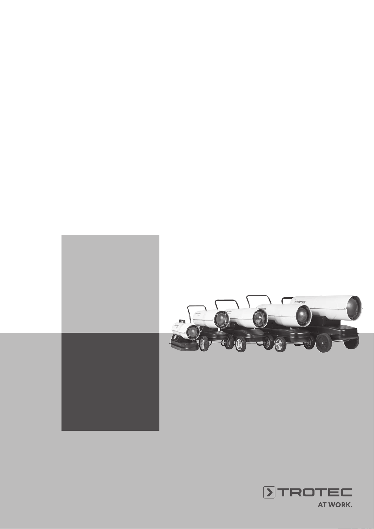
IDE 20 D / IDE 30 D / IDE 50 D
IDE 60 D / IDE 70 D
EN
OPERATING MANUAL
OIL HEATER
TRT-BA-IDE20D-30D-50D-60D-70D-TC-001-EN
Page 2
Table of contents
Notes regarding the operating manual .................................... 1
Information about the device................................................... 3
Safety ..................................................................................... 2
Technical data ........................................................................ 5
Transport and storage............................................................. 9
Operation................................................................................ 10
Errors and faults ..................................................................... 11
Maintenance........................................................................... 12
Disposal.................................................................................. 18
Declaration of conformity........................................................ 18
Notes regarding the operating manual
Symbols
Hazardous electric voltage!
Warns about a hazard from electrical voltage which can
lead to injuries or even death.
Hazard from hot surfaces!
Warns of a hazard resulting from hot surfaces which can
lead to injuries.
Danger!
Warns of a hazard which can lead to injuries.
The current version of the operating manual can be found at:
IDE 20 D
http://download.trotec.com/?sku=1430000050&id=1
IDE 30 D
http://download.trotec.com/?sku=1430000065&id=1
IDE 50 D
http://download.trotec.com/?sku=1430000070&id=1
Caution!
Warns of a hazard which can lead to damage to property.
Legal notice
This release replaces all previous versions. No part of this
publication may be reproduced without written permission from
Trotec. The same applies for electronically processing,
duplicating or spreading the publication. Subject to technical
changes. All rights reserved. Trademarks are used without
guarantee that they may be used freely and primarily following
the spelling of the manufacturer. Product names are registered.
Changes to construction in the interests of constant
improvements to the product, as well as changes to the shape
and colour are reserved.
The scope of delivery may vary from product images. This
document was created with all due care. Trotec accepts no
liability whatsoever for possible mistakes or omissions. © Trotec
IDE 60 D
http://download.trotec.com/?sku=1430000074&id=1
IDE 70 D
http://download.trotec.com/?sku=1430000075&id=1
1 Operating manual – Oil heater IDE 20 D / IDE 30 D / IDE 50 D / IDE 60 D / IDE 70 D EN
Page 3
Safety
Carefully read the operating manual before using the device and keep it within reach!
Danger!
The device becomes very hot!
Improper use of the oil heater can result in severe
injuries due to burns and in an imminent fire
hazard!
• Do not use the device in potentially explosive rooms and do
not install it there. Do not use the device in atmospheres
containing oil, sulphur, chlorine or salt.
• Do not place the device on combustible ground.
• Observe the minimum distance from walls or other objects
(see Technical data).
• Do not position the device near inflammable objects.
• Set the device up in an upright and stable position.
• Make sure that the air inlet and outlet are not obstructed.
• Make sure that the suction side is kept free of dirt and loose
objects.
• Never reach or put objects into the device.
• Never cover the device during operation, for it becomes very
hot!
• Do not transport the device during operation.
• Ensure that all electric cables outside of the device are
protected from damage (e.g. caused by animals).
• Observe the device's power input, cable length and intended
use when selecting extensions to the connecting cable. Avoid
electrical overload.
• Allow the device to cool down completely before transporting
or maintaining it.
• Only transport the device in an upright position. Check the
tank cover for tight fit.
• Do not remove any safety signs, stickers or labels from the
device. Keep all safety signs, stickers and labels in legible
condition.
• Observe the storage and operating conditions (see chapter
Technical data).
Intended use
The device IDE 20 D / IDE 30 D / IDE 50 D / IDE 60 D / IDE 70 D
was developed for the purpose of generating hot air and may only
be used out of doors or in well-ventilated interior spaces whilst
adhering to the technical data (see operating manual).
The device is suited for heating large rooms such as warehouses,
workshops, construction sites, greenhouses or agricultural halls.
It is intended to be used without frequent displacement.
The device may only be used in rooms with sufficient fresh air
supply and exhaust discharge.
The device must only be operated with EL (ultra-light) fuel oil and
diesel, however not with petrol, heavy fuel oil etc.
Every application going beyond these terms of use is prohibited!
Improper use
Do not place the device IDE 20 D / IDE 30 D / IDE 50 D /
IDE 60 D / IDE 70 D on wet or flooded ground. Do not place any
objects on the device. Do not place any objects in the air outlet
area.
Unauthorized modifications or alterations of the device are
forbidden.
Personnel qualifications
People who use this device must:
• be aware of the dangers resulting from heat, fire hazard and
insufficient ventilation when working with oil heaters.
• have read and understood the operating manual, especially
the Safety chapter.
Residual risks
Hazard from hot surfaces!
Parts of the device, especially at the air outlet,
become very hot during operation. There is a
danger of burning and fire. Do not touch the device
during operation! During operation observe a
safety distance of at least 3 m to the device front!
Observe the minimum distance from walls or other
objects according to the technical data!
Danger!
Parts of this appliance can become very hot and
cause burns. Particular attention is to be paid when
there are children or vulnerable persons present!
Danger!
Improper handling entails a risk of burning. Only
use the device as intended!
Danger!
The device must not be covered, there is an
imminent fire hazard!
Hazardous electric voltage!
Work on the electrical components must only be carried
out by an authorised specialist company!
EN Operating manual – Oil heater IDE 20 D / IDE 30 D / IDE 50 D / IDE 60 D / IDE 70 D 2
Page 4
Hazardous electric voltage!
Before any work on the device, remove the mains plug
from the mains socket!
Danger!
The device is not a toy and does not belong in the hands
of children.
Danger!
Dangers can occur at the device when it is used by
untrained people in an unprofessional or improper way!
Observe the personnel qualifications!
Danger!
Do not leave the packaging lying around. Children may
use it as a dangerous toy.
Behaviour in the event of an emergency
1. In case of an emergency, immediately extinguish the pilot
flame by actuating the on/off switch.
2. Disconnect the device from the mains.
Do not reconnect a defective device to the mains.
Information about the device
Device description
The directly fired oil heater serves to heat room air for quickly
heating large rooms. The oil heater runs on EL fuel oil or diesel, it
must not be used with petrol, heavy fuel oil etc.
It is an oil heater with direct combustion to be installed out of
doors or in rooms with a sufficient fresh air supply.
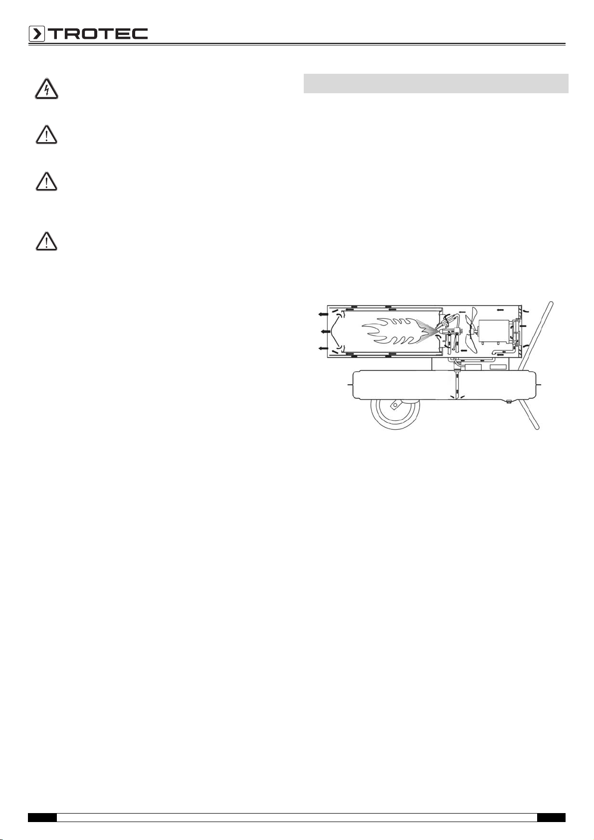
Functional principle
The device generates warmth by conveying the sucked-in, cold
air past a combustion chamber. Inside the combustion chamber
the fuel is burned. The sucked-in air is heated and fed back to the
environment via the air outlet.
The fuel is conducted from the tank to the injection via a pump.
An ignition contact at the injection ignites the fuel, which is then
burned in a continuous flame.
3 Operating manual – Oil heater IDE 20 D / IDE 30 D / IDE 50 D / IDE 60 D / IDE 70 D EN
Page 5
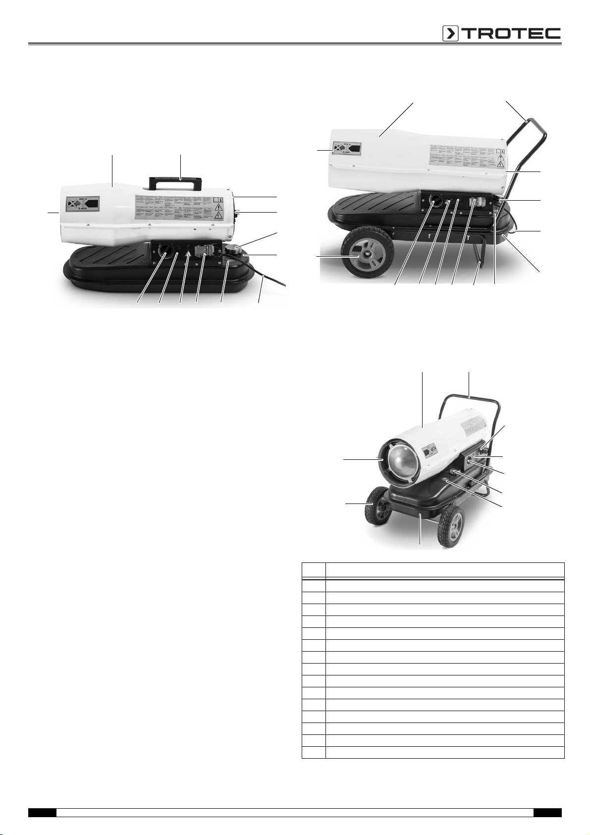
Device depiction
12
4
3
5
6
81012 11
15
713
IDE 20 D
2
1
5
6
7
8
3, 4
91012
15
14
11
IDE 30 D
13
IDE 50 D / IDE 60 D / IDE 70 D
1
2
5
8
11, 12
15
10
14
6
No. Designation
1 combustion chamber housing
2 transport handle
3 air intake opening with protective grid
4 fan and motor
5 fuel tank cap
6tank
7 mains power cable
8 tank filling level indication
9frame
10 connection for external thermostat (lockable)
11 device on/off light
12 on/off switch
13 temperature selection switch
14 wheel
15 air outlet for hot air
EN Operating manual – Oil heater IDE 20 D / IDE 30 D / IDE 50 D / IDE 60 D / IDE 70 D 4
Page 6
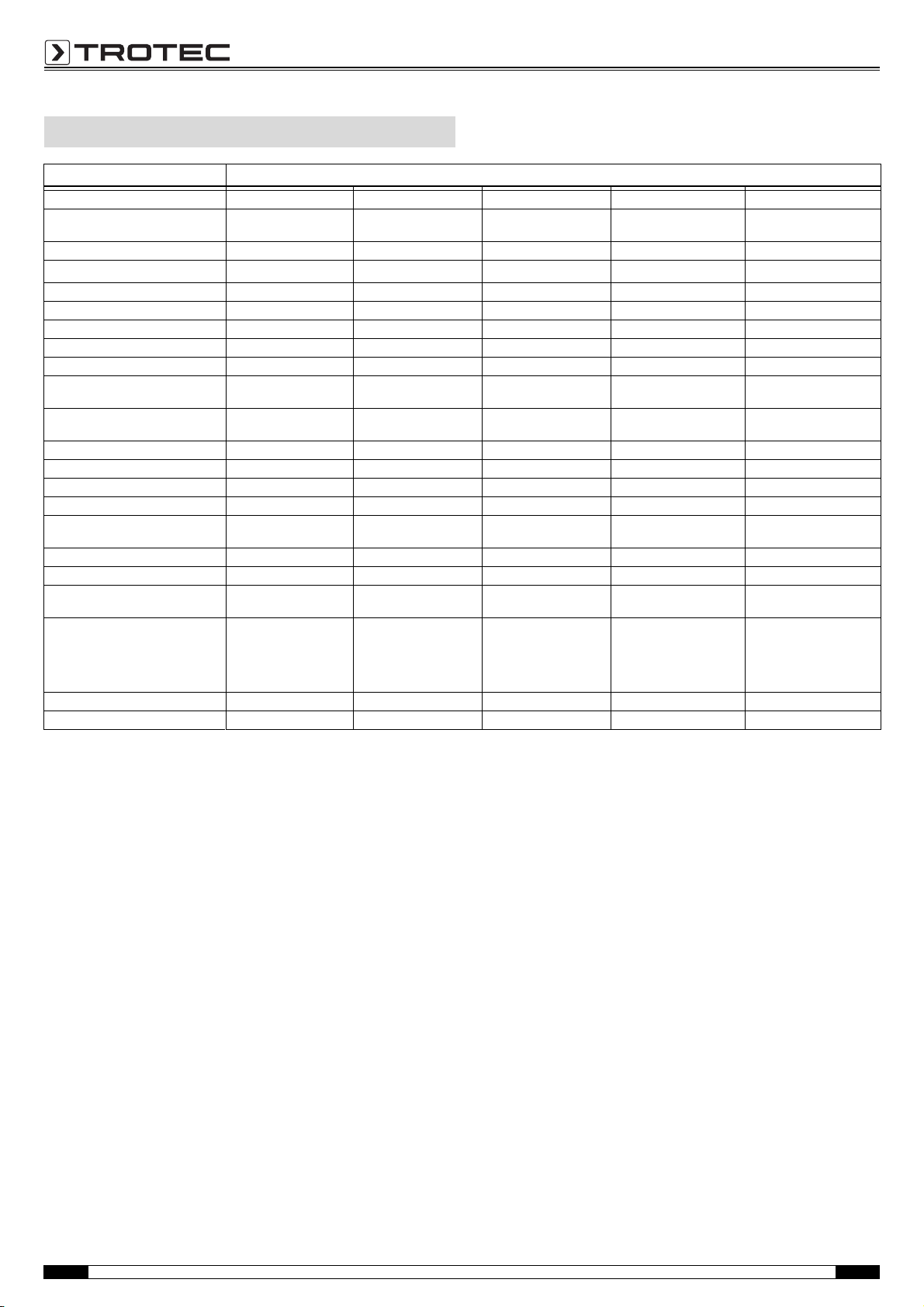
Technical data
Parameter Value
Model IDE 20 D IDE 30 D IDE 50 D IDE 60 D IDE 70 D
Mains connection
(CEE 7 - Schuko plug)
Nominal current 0.71 A 0.84 A 1.25 A 1.5 A 1.8 A
Max. air flow rate
Fan axial fan axial fan axial fan axial fan axial fan
Heating capacity 20 kW 30 kW 50 kW 60 kW 70 kW
Continuous operation 9 h 8 h 9.5 h 9 h 9 h
Ventilation/air changes per hour at least 2 ACH at least 2 ACH at least 2 ACH at least 2 ACH at least 2 ACH
Operating temperature -30 °C to +45 °C -30 °C to +45 °C -30 °C to +45 °C -30 °C to +45 °C -30 °C to +45 °C
Relative humidity during
operation
Storage conditions -35 °C to +40 °C
Max. temperature increase ΔT 140 °C 210 °C 180 °C 150 °C 122 °C
Max. oil consumption 1.2 l/h 2.4 l/h 4 l/h 4.8 l/h 7 l/h
Tank contents 12 l 19 l 38 l 56 l 68 l
Overheating protection yes yes yes yes yes
Connection for external
thermostat
Combustion direct direct direct direct direct
Weight 10 kg 17.5 kg 21.9 kg 27.5kg 40.8 kg
Dimensions (length x width x
height)
Minimum distance to walls or
other objects
Sound pressure level 80 dB (A) 80 dB (A) 90 dB (A) 70 dB (A) 79 dB (A)
Permitted fuel EL fuel oil or diesel EL fuel oil or diesel EL fuel oil or diesel EL fuel oil or diesel EL fuel oil or diesel
230 V / 50 Hz 230 V / 50 Hz 230 V / 50 Hz 230 V / 50 Hz 230 V / 50 Hz
3
650 m
/h 850 m3/h 1100 m3/h 1300m3/h 1300m3/h
max. 90 % RH max. 90 % RH max. 90 % RH max. 90 % RH max. 90 % RH
with 20 % to 80 % RH
45 °C 45 °C 45 °C 45 °C 45 °C
650 x 265 x 395 mm 830 x 430 x 560 mm 850 x 485 x 680 mm 1010 x 530 x 710mm 1120 x 580 x 705 mm
Top: 2 m Top: 2 m Top: 2 m Top: 2 m Top: 2 m
Rear: 2 m Rear: 2 m Rear: 2 m Rear: 2 m Rear: 2 m
Side: 2 m Side: 2 m Side: 2 m Side: 2 m Side: 2 m
Front: 3 m Front: 3 m Front: 3 m Front: 3 m Front: 3 m
-35 °C to +40 °C
with 20 % to 80 % RH
-35 °C to +40 °C
with 20 % to 80 % RH
-35 °C to +40 °C
with 20 % to 80 % RH
-35 °C to +40 °C
with 20 % to 80 % RH
Scope of delivery
1 x Operating manual
1 x Oil heater
1 x Carry handle (IDE 20 D only)
1 x Frame components (IDE 30 D / IDE 50 D / IDE 60 D / IDE 70 D
only)
2 x Wheel (IDE 30 D / IDE 50 D / IDE 60 D / IDE 70 D only)
1 x Installation material
5 Operating manual – Oil heater IDE 20 D / IDE 30 D / IDE 50 D / IDE 60 D / IDE 70 D EN
Page 7
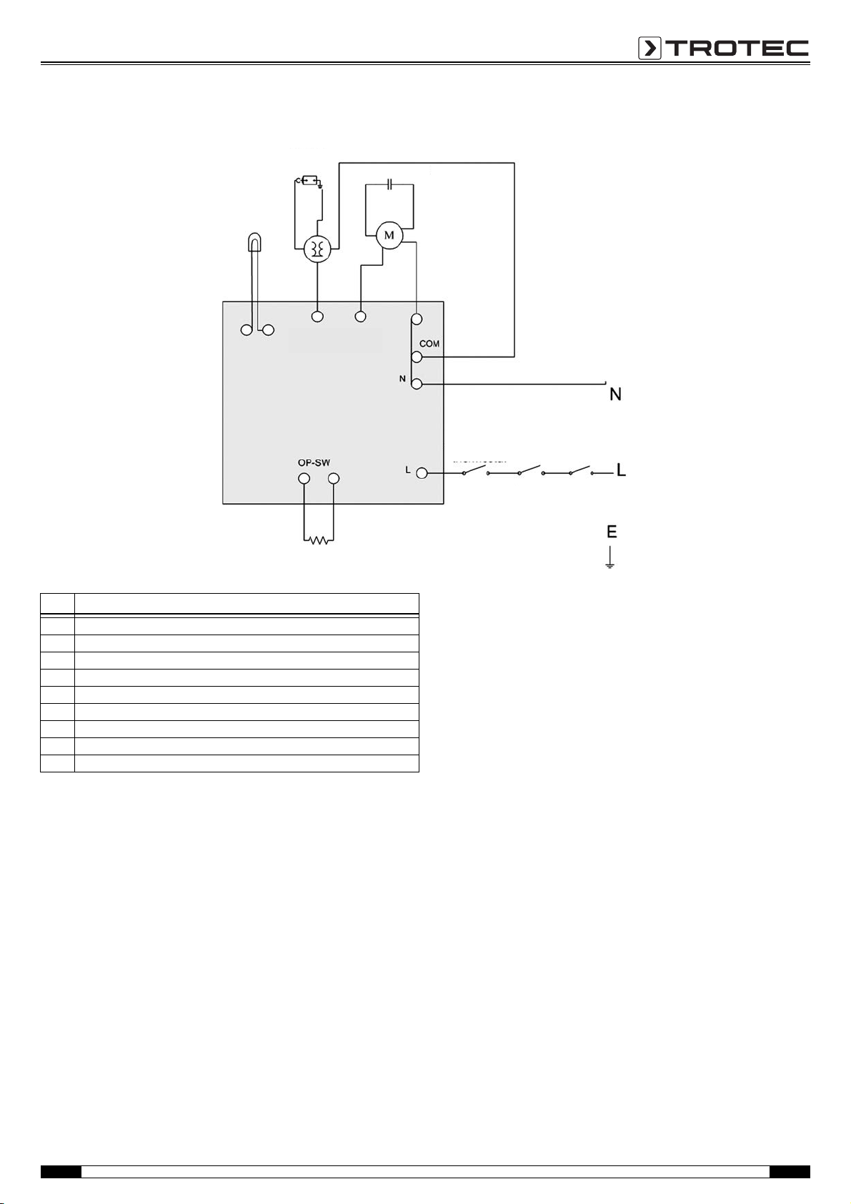
Wiring diagram
16
17
18
21 1920
22
2324
IDE 20 D / IDE 30 D
No. Designation
16 lamp
17 ignition needle
18 capacitance
19 switch
20 thermostat
21 self resetting thermostat
22 light resistance
23 fan
24 ignition
EN Operating manual – Oil heater IDE 20 D / IDE 30 D / IDE 50 D / IDE 60 D / IDE 70 D 6
Page 8
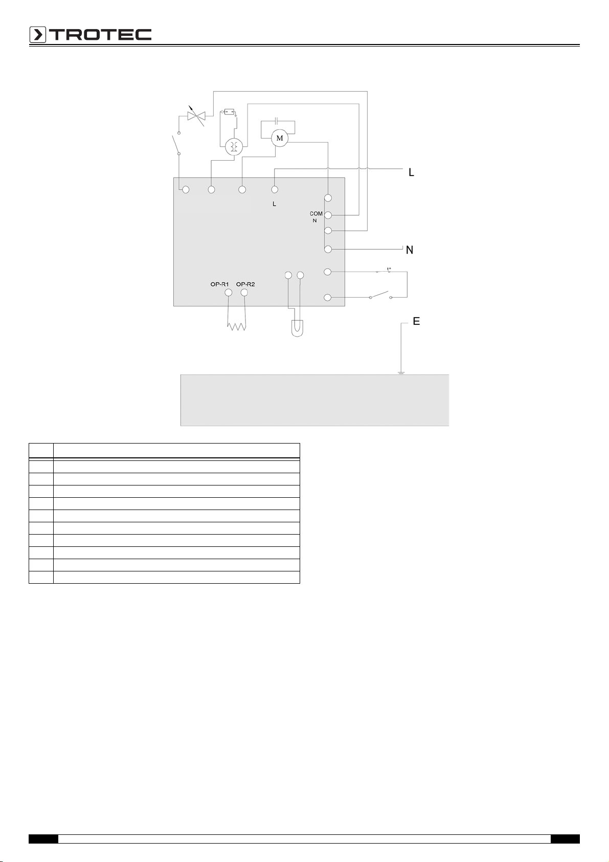
IDE 50 D / IDE 70 D
16
22
19
20
21
17
18
232425
No. Designation
16 lamp
17 ignition needle
18 capacitance
19 switch
20 thermostat
21 self resetting thermostat
22 light resistance
23 fan
24 ignition
25 valve
7 Operating manual – Oil heater IDE 20 D / IDE 30 D / IDE 50 D / IDE 60 D / IDE 70 D EN
Page 9
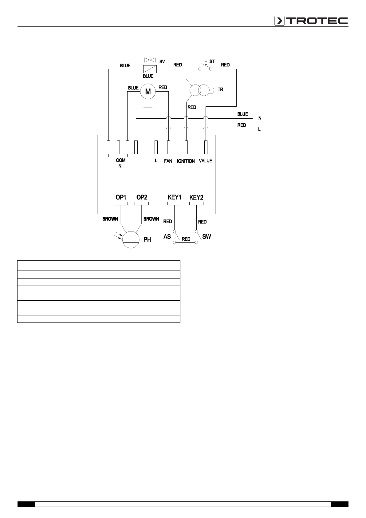
IDE 60 D
No. Designation
Mmotor
TR transformer
PH photocell
SV solenoid valve
ST safety thermostat
SW switch
AS adjustable thermostat
EN Operating manual – Oil heater IDE 20 D / IDE 30 D / IDE 50 D / IDE 60 D / IDE 70 D 8
Page 10
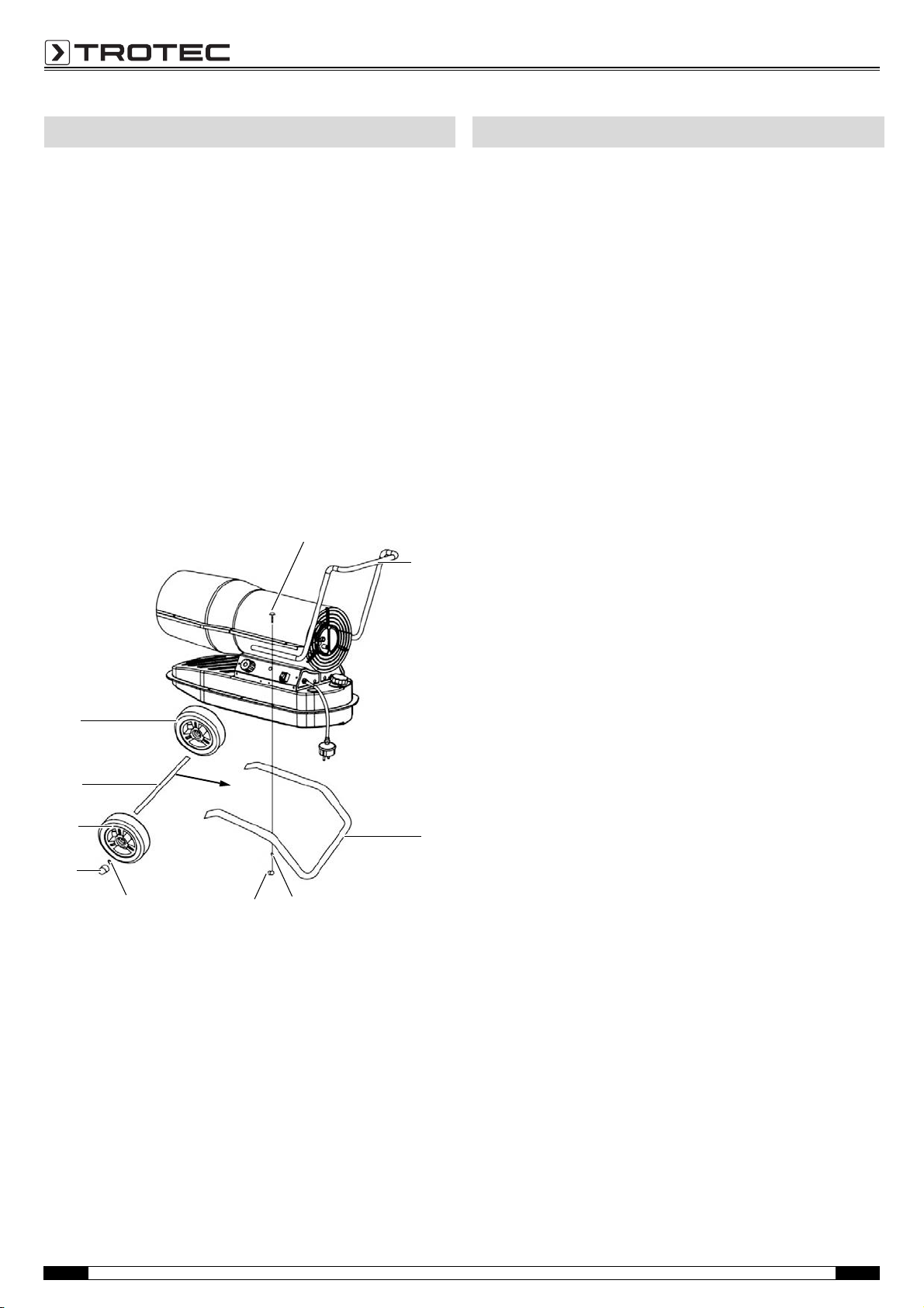
Assembly (IDE 30 D / IDE 50 D / IDE 60 D / IDE 70 D)
2
26
28
27
9
29
13
13
30
31
Transport and storage
Prior to start-up of the device, it has to be assembled.
To do so, please proceed as follows:
1. Insert the axle (31) into the openings at the front part of the
frame (9).
2. Attach the wheels (13) to the axle (31).
3. Affix the bearing bushings (29) to both ends of the axle (31),
then add the protective caps (30).
– The wheels are mounted.
4. Place the device on the frame (9). Make sure that the bore
holes for the screws are aligned, see figure below.
5. Position the transport handle (2) above the rear bore holes.
6. Insert one of the screws (26) and fasten it with washer (27)
and nut (28).
7. Repeat this process with the remaining screws.
– The device is assembled and can be positioned.
Transport
Before transporting the device, proceed as follows:
1. Switch off the device.
2. Wait until the device has cooled down completely.
3. Remove the mains plug from the mains socket. Do not use
the power cable to drag the device!
4. Check the tank cover for leakage and tight fit.
Transporting the IDE 20 D
1. Only transport the IDE 20 D by use of the transport handle (2).
Transporting the IDE 30 D / IDE 50 D / IDE 60 D / IDE 70 D
1. Slightly lift the device by the transport handle (2) until the rear
support no longer touches the ground.
2. Wheel the device to the desired position.
Storage
Drain the tank before storage (see chapter Maintenance).
When the device is not being used, observe the following storage
conditions:
•dry,
• protected from dust and direct sunlight,
• with a plastic cover to protect it from invasive dust, if
necessary.
9 Operating manual – Oil heater IDE 20 D / IDE 30 D / IDE 50 D / IDE 60 D / IDE 70 D EN
Page 11
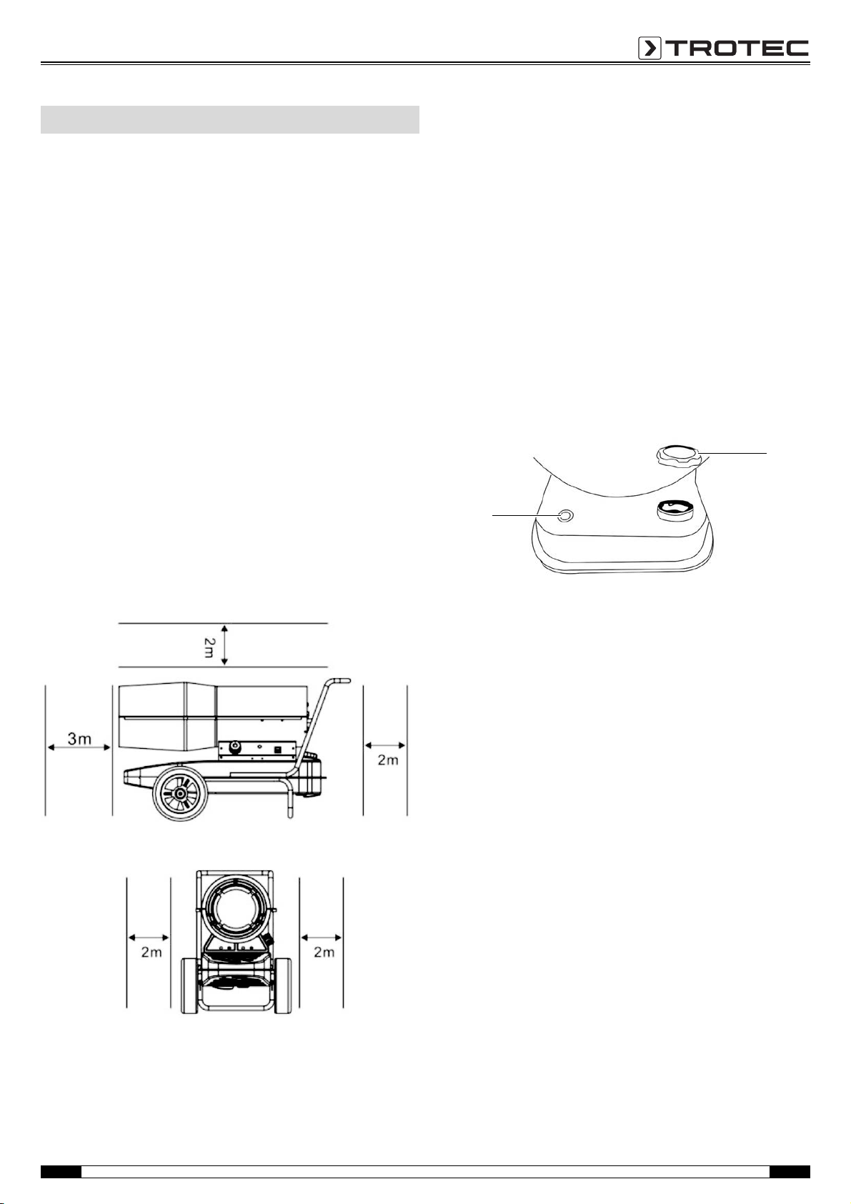
Operation
8
5
Installing the device
A number of spatial and technical conditions have to be
considered for the selection of the oil heater's installation site.
Non-observance would compromise the proper functioning of the
device or the accessories or entail the risk of personal injury and
property damage.
The following is to be observed for positioning:
• The device may only be operated in sufficiently ventilated
interior spaces.
• The device must be connected to a properly secured mains
power socket.
• The device is to be set up in a stable position on
incombustible ground (see chapter Technical data and figure
below).
• The minimum distance between the wall and the air
intake opening of the device must be at least 2 m (see
figure below).
• The minimum distance between the device and
combustible materials must be at least 3 m (see figure
below).
• Air inlet and outlet must not be covered.
• There must be a sufficient number of fire extinguishers
available.
Filling the tank
The tank cover and the filling level indication of the IDE 20 D / IDE
30 D are located at the rear of the device, those of the IDE 50 D /
IDE 60 D / IDE 70 D are located on the left side of the control
panel.
• Before attempting to fill the tank, wait until the device has
cooled down completely.
• Only fill the tank with fuel suitable for the device (see
Technical data).
• Position the device on firm, level and incombustible ground.
• Unscrew the fuel tank cap (5).
• Fill the tank. In doing so, observe the filling level
indication (8).
• Screw the fuel tank cap (5) back onto the tank. Make sure
that the tank is firmly attached to avoid leakage.
Start-up
• Check the oil heater and its connection parts for potential
damage.
• Fill the tank with fuel oil when the device is switched off and
cooled down.
• Check whether the characteristics of the power grid conform
to those on the rating plate.
• Connect the power supply cable to a properly secured mains
socket (230 V / 50 Hz).
Switching the device on
1. Set the on/off switch (12) to position I.
2. Set the selection switch (13) to the desired temperature
range.
3. Ensure that the flame was actually ignited by the ignition
contact before leaving the device unattended.
4. If the selected temperature range is below the ambient
temperature, the device will not switch on or else switch itself
off again.
EN Operating manual – Oil heater IDE 20 D / IDE 30 D / IDE 50 D / IDE 60 D / IDE 70 D 10
Page 12
Switching the device off
1. Set the on/off switch to position 0.
2. Remove the mains plug when the fan is at a standstill.
3. Check whether the flame is really extinguished.
4. Before performing any further activities, e.g. storage,
transport or maintenance, wait until the device has cooled
down completely.
Errors and faults
The device has been checked for proper functioning several times
during production. If malfunctions occur nonetheless, check the
device according to the following list.
Troubleshooting tasks which require the housing to
be opened must only be carried out by Trotec.
Smoke and/or sparks are emitted during first use:
• This is not a fault. These phenomena disappear after a brief
runtime.
Noise emission during ignition or cooling:
• This is not a fault. The metal parts of the device expand when
heated and generate noise.
Sparks and/or flame leave the device during ignition:
• This is not a fault. Air might have accumulated in the lines.
Keep a safety distance to the device!
The device does not start:
• Check the power connection (230 V/1~/50 Hz).
• Check the mains plug for damages.
• Check the filling level of the tank. Refill with fuel if the tank is
empty (see chapter Operation).
• Have an electrical inspection carried out by Trotec.
The flame in the combustion chamber does not ignite:
• Check the filling level of the tank. Refill with fuel if the tank is
empty (see chapter Operation).
• Check the fuel for contaminations, e.g. dirt or water.
• Safety shutdown: If the flame dies during operation, the
electronics and the oil pump will be switched off – investigate
the cause on the basis of the following criteria:
– For qualified personnel only!
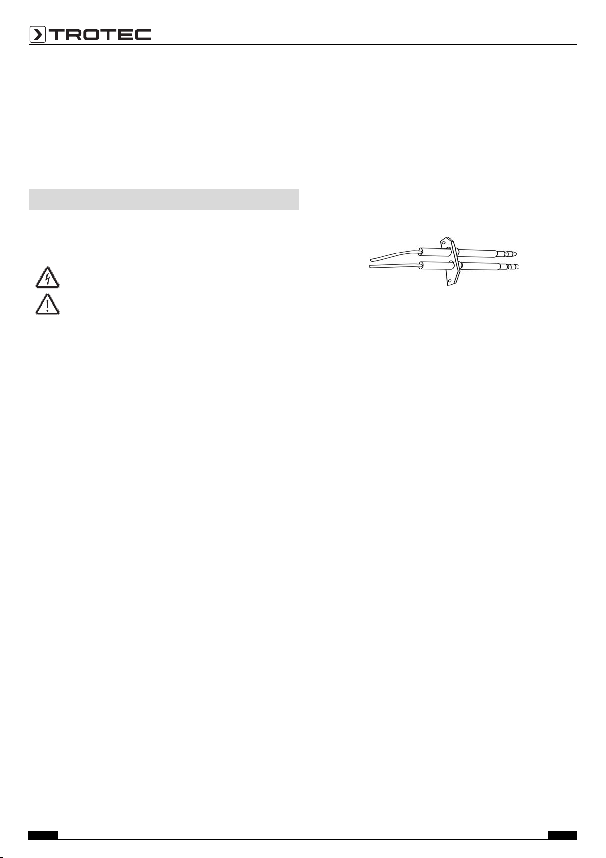
Check the ignition: The distance between the two ignition
electrodes should be 4 to 5 mm.
The flame goes out during combustion:
• Make sure the air supply is unobstructed. If required, clean
the air intake opening.
• Check the fuel for contaminations and replace it if required.
• Check the filling level of the tank. Refill with fuel if the tank is
empty (see chapter Operation).
• Power failure: In the event of a power failure the ignition is
extinguished, the device switches off immediately. After a
power failure the device will not restart automatically, it has
to be started via the on/off switch.
There is a fuel leak:
• Check whether too much fuel was filled in.
• Check the drain screw for tight fit and retighten it if
necessary.
• Check the sealing at the drain screw and replace it if
damaged.
The device emits smoke or dust:
• Check the mains voltage.
• Check the fuel for contaminations and replace it if required.
• Check the tank for contaminations and drain it if required (see
chapter Maintenance). Refill with clean fuel.
11 Operating manual – Oil heater IDE 20 D / IDE 30 D / IDE 50 D / IDE 60 D / IDE 70 D EN
Page 13
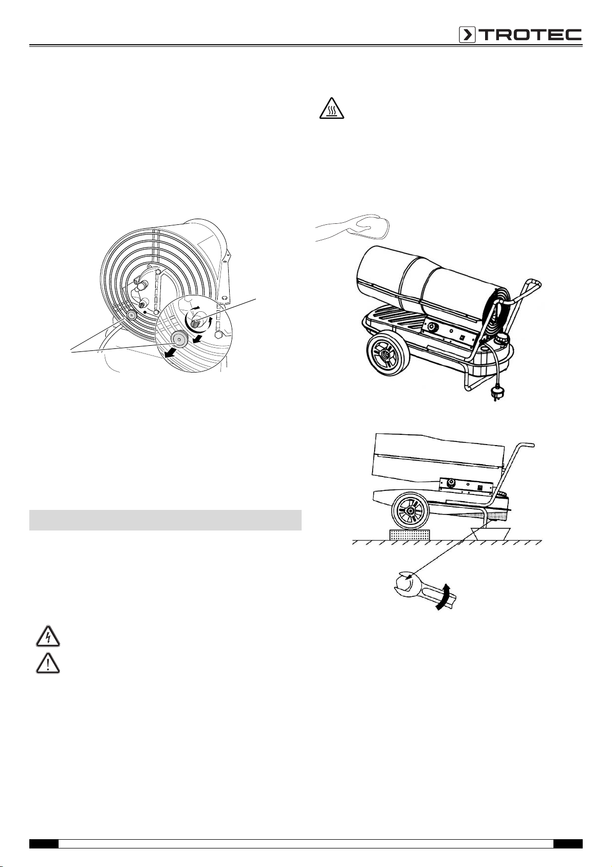
The flame emerges from the air outlet:
33
32
• Check the mains voltage.
• Check the fuel for contaminations and replace it if required.
• Check the tank for contaminations and drain it if required (see
chapter Maintenance). Refill with clean fuel.
• For qualified personnel only!
It is possible to readjust the oil feed if required:
– Remove the white protective cap (33) from the rear air
intake opening.
Cleaning the housing
Hazard from hot surfaces!
There is a danger of burning.
Allow the device to cool down completely before
cleaning the housing!
Clean the device with a soft, damp and lint-free cloth. Ensure that
no moisture enters the housing. Do not use any sprays, solvents,
aggressive cleaning agents or abrasive cleaners. Only use clean
water to moisten the cloth.
– Adjust the oil feed by means of a slotted screwdriver. For
lowering turn the screw (32) counter-clockwise; for
increasing carefully turn it clockwise.
– Reattach the white protective cap (33).
Your device still does not operate correctly after these checks?
Please contact the Trotec customer service.
Maintenance
Activities required before starting maintenance
• Do not touch the mains plug with wet or damp hands.
• Allow the device to cool down completely before performing
any work!
• Before any work, remove the mains plug!
Maintenance tasks which require the housing to be opened must only be carried out by Trotec
Draining the tank
1. Provide for a suitable collection container.
2. Move the device to an elevated position.
3. As indicated in the figure use a wrench to open the screw at
the bottom of the tank.
4. Drain the fuel into the collection container.
5. When no more fuel is discharged, seal the drain hole again.
– Ensure the tight fit of the screw and, if required, replace the
seal, for otherwise fuel might leak out uncontrollably.
6. Dispose of the fuel according to national regulations.
EN Operating manual – Oil heater IDE 20 D / IDE 30 D / IDE 50 D / IDE 60 D / IDE 70 D 12
Page 14
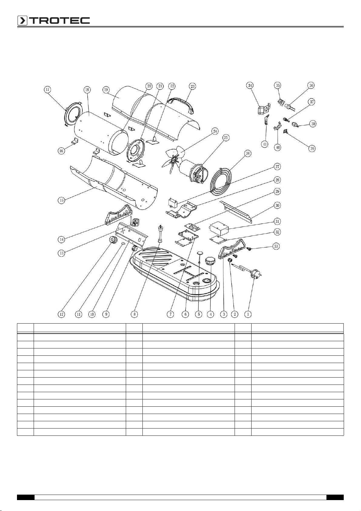
Overview and list of spare parts
Note!
The position numbers of the spare parts differ from those describing the positions
of other parts mentioned in this operating manual.
IDE 20 D
No. Spare part No. Spare part No. Spare part
1 power cord 15 bottom cover 29 power PCB
2 lock 16 heat insulation casing bracket 30 side plate
3 back casing support 17 air outlet 31 ignition transformer
4 fuel tank cap 18 heat insulation casing 32 bracket of ignition transformer
5 oil leveler 19 top cover 33 support
6 fuel tank 20 combustion chamber 34 bracket of nozzle base
7 power PCB bracket 21 burner support plate 35 photocell assembly bracket
8 fuel filter 22 air deflector 36 photocell assembly
9 on/off switch 23 handle 37 nozzle assembly
10 control panel 24 fan 38 nozzle base
11 light cover 25 motor assembly 39 reset thermostat
12 thermostat knob 26 back grill 40 reset thermostat bracket
13 capillary thermostat 27 capacitator 41 ignition needle
14 casing front support 28 motor support
13 Operating manual – Oil heater IDE 20 D / IDE 30 D / IDE 50 D / IDE 60 D / IDE 70 D EN
Page 15
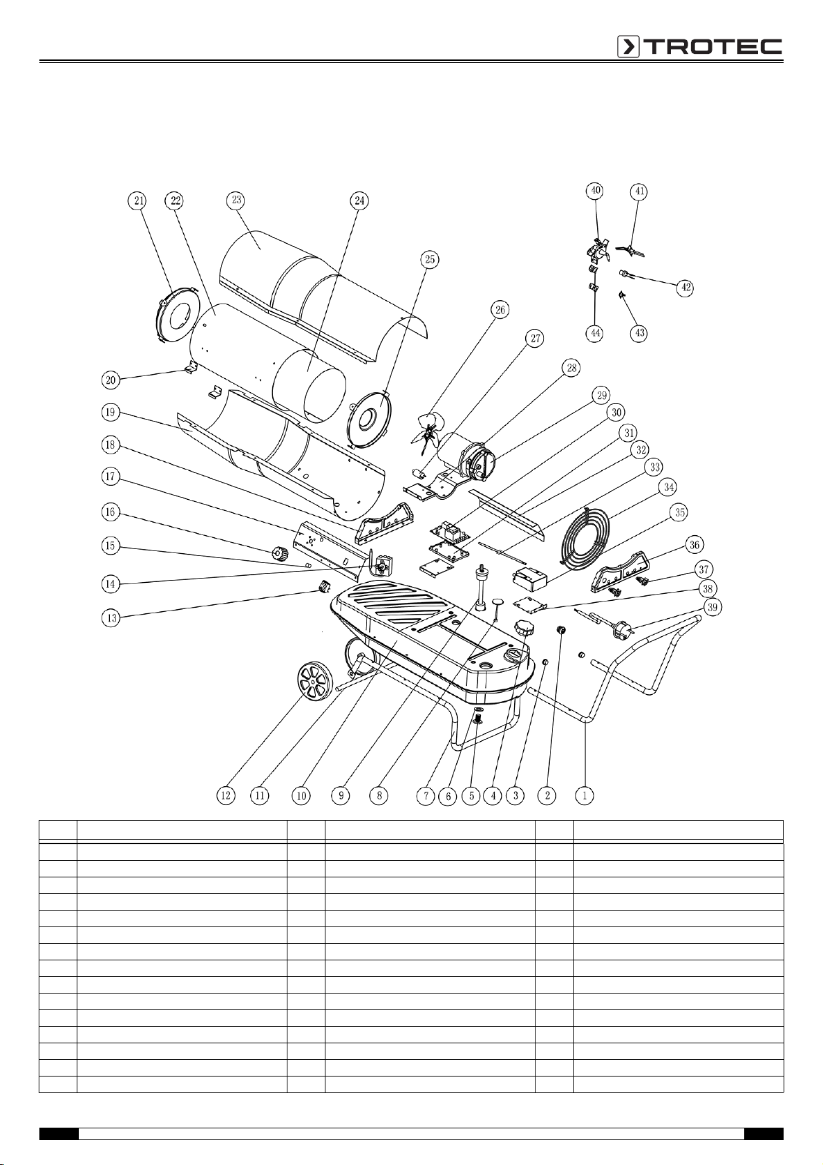
IDE 30 D
Note!
The position numbers of the spare parts differ from those describing the positions
of other parts mentioned in this operating manual.
No. Spare part No. Spare part No. Spare part
1 handle 16 thermostat knob 31 PCB bracket
2 lock 17 control panel 32 side plate
3 feet pipe cover 18 casing front support 33 high voltage cable
4 fuel tank cap 19 bottom cover 34 back grill
5 oil drain screw 20 heat insulation casing bracket 35 ignition transformer
6 oil drain seal ring 21 air outlet 36 casing back support
7 feet pipe 22 heat insulation casing 37 support
8 oil leveler 23 top cover 38 bracket of ignition transformer
9 fuel filter 24 combustion chamber 39 power cord
10 fuel tank 25 fixed plate of flame plate 40 flame plate
11 wheel axle 26 fan 41 ignition needle
12 wheel 27 capacitator 43 reset thermostat
13 on/off switch 28 motor support 44 reset thermostat bracket
14 capillary thermostat 29 motor assembly
15 light cover 30 power PCB
EN Operating manual – Oil heater IDE 20 D / IDE 30 D / IDE 50 D / IDE 60 D / IDE 70 D 14
Page 16
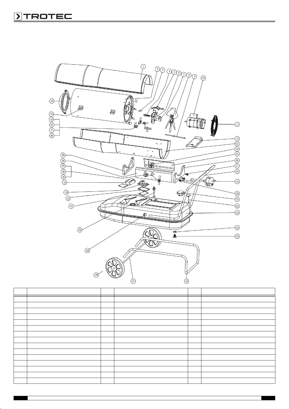
IDE 50 D
Note!
The position numbers of the spare parts differ from those describing the positions
of other parts mentioned in this operating manual.
No. Spare part No. Spare part No. Spare part
1 top cover 16 casing back support 31 bracket of ignition transformer
2 combustion chamber 17 support 32 PCB bracket
3 air deflector 18 handle 33 power PCB
4 nozzle assembly 19 power cord 34 ignition transformer
5 ignition needle 20 lock 35 thermostat knob
6 flame plate 21 fuel tank cap 36 light cover
7 solenoid valve 22 oil leveler 37 on/off switch
8 fan 23 fuel tank 38 control panel
9 high voltage cable 24 oil drain seal ring 39 casing front support
10 motor assembly 25 oil drain screw 40 photocell assembly bracket
11 back grill 26 feet pipe 41 reset thermostat bracket
12 motor support 27 wheel axis 42 reset thermostat
13 bottom cover 28 whee 43 photocell assembly
14 capillary thermostat 29 feet pipe cover 44 heat insulation casing bracket
15 side plate 30 fuel filter 45 air outlet
15 Operating manual – Oil heater IDE 20 D / IDE 30 D / IDE 50 D / IDE 60 D / IDE 70 D EN
Page 17
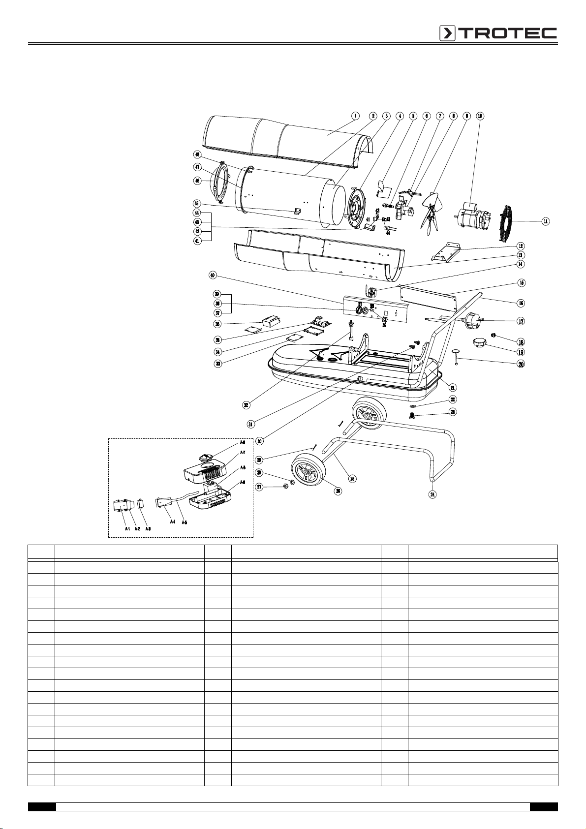
IDE 60 D
Note!
The position numbers of the spare parts differ from those describing the positions
of other parts mentioned in this operating manual.
No. Spare part No. Spare part No. Spare part
1 Top cover 20 Oil level gauge 39 on/off switch
2 Heat insulation casing 21 Fuel tank 40 Control plate
3 Combustion chamber 22 Oil drain seal ring 41 Photocell bracket
4 Burner support plate 23 Oil drain screw 42 Re-set thermostat bracket
5 Air deflector 24 Foot pipe 43 Re-set thermostat
6 Nozzle 25 Wheel axle 44 Photocell
7 Ignition electrode 26 Wheel 45 Heat Insulation casing bracket
8 Flame plate 27 Screw nut 46 Air outlet cover support
9 Fan 28 Flat washer 47 Support ring
10 Motor assembly 29 Cotter pin 48 Clamp
11 Air inlet grid 30 Foot pipe cover A-1 Socket
12 Motor support 31 Support A-2 Buckle
13 Bottom cover 32 Fuel filter A-3 Socket cap
14 Capillary thermostat 33 Bracket of Ignition transformer A-4 Pulg
15 Side plate 34 PCB bracket A-5 Wire
16 Handle 35 Power PCB A-6 Knob
17 Power cord 36 Ignition transformer A-7 Top cover
18 Lock 37 Thermostat knob A-8 Capillary Thermostat
19 Fuel tank cap 38 Light cover A-9 Bottom cover
EN Operating manual – Oil heater IDE 20 D / IDE 30 D / IDE 50 D / IDE 60 D / IDE 70 D 16
Page 18
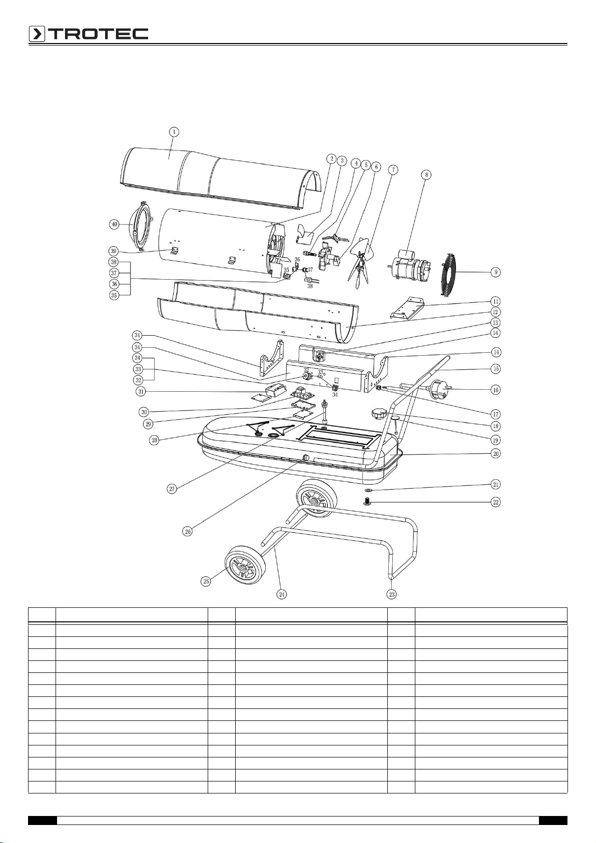
IDE 70 D
Note!
The position numbers of the spare parts differ from those describing the positions
of other parts mentioned in this operating manual.
No. Spare part No. Spare part No. Spare part
1 top cover 15 handle 29 PCB 1 bracket
2 combustion chamber 16 power cord 30 power PCB 1
3 air deflector 17 lock 31 ignition transformer
4 nozzle assembly 18 fuel tank cap 32 thermostat knob
5 ignition needle 19 oil leveler 33 light cover
6 flame plate assembly 20 fuel tank 34 knob
7 fan 21 oil drain seal ring 35 photocell assembly bracket
8 motor assembly 22 oil drain screw 36 reset thermostat bracket
9 back grill 23 feet pipe 37 thermo cut-off
10 air outlet bend connector 24 wheel axis 38 photocell assembly
11 motor support 25 wheel 39 heal insulation casing bracket
12 bottom casing 26 feet pipe cover 40 air outlet
13 adjustable thermostat 27 plastic oil suction pipe
14 front support 28 ignition transformer bracket
17 Operating manual – Oil heater IDE 20 D / IDE 30 D / IDE 50 D / IDE 60 D / IDE 70 D EN
Page 19
Disposal Declaration of conformity
In the European Union, electronic equipment must not
be treated as domestic waste, but must be disposed of
professionally in accordance with Directive
2002/96/EC of the European Parliament and of the Council of
27 January 2003 on waste electrical and electronic equipment
(WEEE). At the end of its life, please dispose of this device
according to the relevant legal requirements.
Fuels
For disposal of the used fuels always observe the national
regulations.
in accordance with the EC Low Voltage Directive 2006/95/EC and
the EC Directive 2004/108/EC about electromagnetic
compatibility.
Herewith, we declare that the oil heaters IDE 20 D, IDE 30 D, IDE
50 D, IDE 60 D and IDE 70 D were developed, constructed and
produced in compliance with the named EC directives.
Applied harmonised standards:
EN 60335-1:2012
EN 60335-2-102:2006/A1:2010
EN 62233:2008
EN 55014-1:2006/A1:2009 and A2:2011
EN 55014-2:1997/A1:2001 and A2:2008
EN 61000-3-2:2006/A1:2009 and A2:2009
EN 61000-3-3:2013
Further applied standards:
EN 13842:2004
EN 62321:2009
The marking is found on the rear of the device.
Manufacturer:
Trotec GmbH & Co. KG
Grebbener Straße 7
D-52525 Heinsberg
Heinsberg, 14/10/2014
Managing Director: Detlef von der Lieck
EN Operating manual – Oil heater IDE 20 D / IDE 30 D / IDE 50 D / IDE 60 D / IDE 70 D 18
Page 20

Trotec GmbH & Co. KG
Grebbener Str. 7
D-52525 Heinsberg
+49 2452 962-400
+49 2452 962-200
[email protected]
www.trotec.com
 Loading...