

Page 1
Instruction Handbook
Advanced
CLP 4532
Colour Printer
Page 2

Page 3

Contents
1 Handling Paper ..............................................................................................1-1
General Guidelines ................................................................................................................. 1-2
Selecting the Right Paper ....................................................................................................... 1-4
Paper Type ............................................................................................................................ 1-10
2 Using the Operation Panel ...........................................................................2-1
General Information ................................................................................................................ 2-2
Understanding the Operation Panel ........................................................................................ 2-3
Canceling a Printing Job ......................................................................................................... 2-8
Using the Menu Selection System .......................................................................................... 2-9
Status Pages ......................................................................................................................... 2-12
e-MPS ................................................................................................................................... 2-15
Changing the Interface Parameters ...................................................................................... 2-24
Making Default Settings ........................................................................................................ 2-30
Pagination ............................................................................................................................. 2-38
Setting Print Quality ............................................... .................................. ..... ...... .................. 2-41
Operating the Storage Device ............................................................................................... 2-42
Paper Handling ..................................................................................................................... 2-50
Selecting Monochrome or Color Printing .............................................................................. 2-63
Reading Life Counters .......................................................................................................... 2-64
Other Modes ......................................................................................................................... 2-65
3 Options ..........................................................................................................3-1
General Information ................................................................................................................ 3-2
Expansion Memory Modules ................................................................................................... 3-5
Network Interface .................................................................................................................... 3-8
Hard Disk ................................................................................................................................ 3-9
CompactFlash (Memory) Card .............................................................................................. 3-10
4 Computer Interface ................................. .... ..................................................4-1
General Information ................................................................................................................ 4-2
Parallel Interface ..................................................................................................................... 4-3
USB Interface .......................................................................................................................... 4-5
Serial Interface (Option) .......................................................................................................... 4-6
RS-232C Protocol ................................................................................................................... 4-7
Glossary ....................................................................................................... Glossary-1
Index ................................................................................................................... Index-1
i
Page 4

ii
Page 5

Introduction
This guide has the following chapters:
1 Handling Paper
Explains how choose, handle and load paper.
2 Using the Operation Panel
Explains how to use the operation panel to configure the printer.
3 Options
Shows the available options.
4 Computer Interface
Describes the possible connections between the printer and your computer.
Glossary
A Glossary of terms used is provided here.
iii
Page 6

Conventions
This manual uses the following conventions:
Convention Description Example
Italic T ypeface Used to emphasize references
to additional information.
Courier T ypeface Used to denote messages or
names displayed on the
operation panel.
Bracket Bold T e xt
Typeface
Bold T ypeface Used to emphasize button or
Note Used to provide additional or
Used to denote operatio n panel
keys.
items to be selected in dialog
boxes, and titles displaying in
dialog boxes.
useful information about a
function or feature.
Refer to T oner Cont ainer Replacemen t on
page 3-3.
Replace the waste toner box when the
Check waste toner box message is
displayed.
Press [Menu].
Click Next.
NOTE: For information about storing the
pin, refer to step 10.
Important Use to provide important
information.
Caution Cautions are statements that
suggest mechanical damage
as a result of an action.
Warning Used to alert users to the
possibility of personal injury.
IMPORTANT: Ensure pa per is not folde d,
curled, or damaged.
CAUTION: Do not pull the cassette out
when holding the front of the machine.
WARNING: High voltage is present in
the charger section.
iv
Page 7

1 Handling Paper
This chapter contains ex planations on the following topics:
• General Guidelines...1-2
• Selecting the Right Paper...1-4
• Paper Type...1-10
1-1
Page 8

Handling Paper
General Guidelines
The machine is designed to print on standard copier paper (the type used in ordinary dry copier
machines), but it can also accept a variety of other types of paper within the limits specified below.
NOTE: The manufacturer assumes no liability for problems that occur when paper not satisfying
these requirements is used.
Selection of the right paper is important. Using the wrong paper can result in paper jams, curling,
poor print q ual ity, and paper waste, a nd in extreme cases can d am age the machine. The g ui del ines
given below will increase the productivity of your office by ensuring efficient, trouble-free printing
and reducing wear and tear on the machine.
Paper Availability
Most types of paper are compatible with a variety of machines. Paper intended for xerographic
copiers can also be used with the machine.
There are three general grades of paper: economy, standard, and premium. The most significant
difference between grades is the ease with which they pass through the machine. This is affected
by the smoothness, size, and mois ture co nten t of the paper, and the way in which the paper is cut.
The higher the grade of p aper you us e, the les s risk there w ill be of pa per jams and other pr oblems,
and the high er the level of quality your printed output will reflect.
Differences between paper from different suppliers can also affect the machine’s performance. A
high-quality printer cannot produce high-quality results when the wrong paper is used. Low-priced
paper is not economical in the long run if it causes printing problems.
Paper in each gra de is av ai lab le in a range of basis weights (defined la ter). The traditional standard
weights are 60 to 105 g/m² (16 to 28 lb/ream).
Paper Specifications
The following table summarizes the basic paper specifications. Details are given on the following
pages.
Item Specification
Weight Cassette: 60 to 105g/m² (16 to 28 lb/ream)
Thickness 0.086 to 0.110 mm (3.4 to 4.3 mils)
Dimensions Refer to Paper Sizes on page 1-4.
Dimensional accuracy ±0.7 mm
Squareness of corners 90° ±0.2°
Moisture content 4% to 6%
Direction of grain Long grain
Pulp content 80% or more
MP Tray: 60 to 220 g/m² (16 to 53 lb/ream)
1-2
Page 9
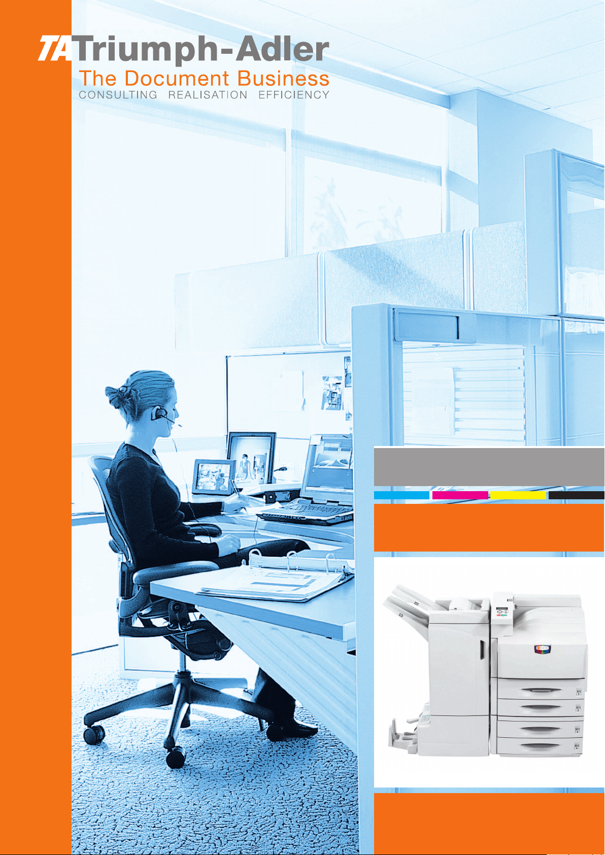
Minimum and Maximum Paper Sizes
The minimum and maximum paper sizes are as follows. For non standard paper, the MP tray must
be used.
Paper cassette
Handling Paper
MP tray
Recommended Paper
The following products are recommended for use with the printer for optimum performance
Minimum
Paper Size
210 mm
8-1/4 inches
432 mm
17 inches
140 mm
5-1/2 inches
Maximum
Paper Size
297 mm
11-11/16 inches
432 mm
17 inches
Minimum
Paper Size
148 mm
5-13/16 inches
98 mm
3-3/8 inches
Maximum
Paper Size
297 mm
11-11/16 inches
Size Product Weight
Letter, Legal Hammermill LASER PRINT 90 g/m² (24 lb)
A4 NEUSIEDLER COLOR COPY 90 g/m²
1-3
Page 10

Handling Paper
Selecting the Right Paper
This section describes the guidelines for selecting paper.
Condition
Avoid using paper that is bent at the edges, curled, dirty, torn, embossed, or contaminated with lint,
clay, or paper shreds.
Use of paper in these conditions can lead to illegible printing and paper jams, and can shorten the
life of the machin e. In p articular, avoid using paper with a s urface coati ng or othe r surface treatment.
Paper should have as smooth and even a surface as possible.
Composition
Do not use paper that has been coated or surface-treated and contains plastic or carbon. The heat
of fusing can cause such paper to give off harmful fumes.
Bond paper should contain at least 80% pulp. Not more than 20% of the total paper content should
consist of cotton or other fibers.
Paper Sizes
Cassettes and the MP tray are available for the paper sizes listed in the table below. The
dimensional tolerances are ±0.7mm for the length and width. The angle at the corners must be 90°
±0.2°.
MP tray Size Cassette or
MP tray
Envelope C4 229 × 324 mm Ledger 11 × 17 inches
Envelope C5 162 × 229 mm Legal 8-1/2 × 14 inches
Envelope Monarch 3-7/8 × 7-1/2 inches Letter 8-1/2 × 11 inches
Executive 7-1/4 × 10-1/2 inches ISO A3 297 × 420 mm
Envelope #10 4-1/8 × 9-1/2 inches ISO A4 210 × 297 m m
Envelope DL 110 × 220 mm ISO A5 148 × 210 mm
Envelope #9 3-7/8 × 8-7/8
Envelope #6 3-5/8 × 6-1/2 inches JIS B5 182 × 257 mm
ISO B5 176 × 250 mm Statement 5-1/2 × 8-1/2 inches
ISO A6 105 × 148 mm Oficio II 8-1/2 × 13 inches
JIS B6 128 × 182 mm Folio 210 × 330mm
Hagaki 100 × 148 mm 8 kai 273 × 394 mm
Ofuku-Hagaki 148 × 200 mm 16 kai 197 × 273 mm
Youkei 2 114 × 162 mm
Youkei 4 105 × 235 mm
Custom 98 × 148 to 297 × 4 32mm
(3-3/8 × 5-13/16 to
11-11/16 × 17 inches)
inches JIS B4 257 × 364 mm
Size
Smoothness
1-4
The paper should have a smooth, uncoated surface. Paper with a rough or sandy surface can
cause voids in the printed output. Paper that is too smooth can cause multiple feeding and fogging
problems. (Fogging is a gray background effect.)
Page 11

Basis Weight
Basis weight is the weight of paper expressed in grams per square meter (g/m²). Paper that is too
heavy or too light may cause feed errors or paper jams as well as premature wear of the product.
Uneven weight of pa per, namely uneven paper thickness may ca us e mu ltip le -sh eet feeding or print
quality problems such as blurring because of poor toner fusing.
The recommended basis weight is between 60 and 105 g/m² (16 and 28 lb/ream) for the cassette
and between 60 and 220 g/m² (16 to 53 lb/ream) for the MP tray.
Paper Weight Equivalence Table
The paper weight is listed in pounds (lb) and metric grams per square meter (g/m²). The shaded
part indicates the standard weight.
U. S. Bond Weight (lb) Europe Metric Weight (g/m²)
16 60
17 64
20 75
21
22 81
24 90
27
28 105
32 120
34 128
36 135
39 148
42 157
43 163
47 176
53 199
80
100
Handling Paper
Thickness
Moisture Content
The paper used with the machine should be neither extremely thick nor extremely thin. If you are
having problems with p a per jams , multip le feeds , and fain t print ing, the p a per you are using ma y be
too thin. If you are havi ng pro blems with paper jams and blurred printi ng the pa per ma y be too thick.
The correct thickness is 0.086 to 0.110 mm (3.4 to 4.3 mils).
Moisture content is defined as the percent ratio of moisture to the dry mass of the paper. Moisture
can affect the paper’s appearance, feed ability, curl, electrostatic properties, and toner fusing
characteristics.
The moisture content of the paper varies with the relative humidity in the room. When the relative
humidity is high and the paper absorbs moisture, the paper edges expand, becoming wavy in
appearance. When the relative humidity is low and the paper loses moisture, the edges shrink and
tighten, and print contrast may suffer.
Wavy or tight edges can cause jams and alignment anomalies. The moisture content of the paper
should be 4 to 6%.
1-5
Page 12

Handling Paper
To ensure correct moisture content, it is important to store the paper in a controlled environment.
Some tips on moisture control are:
• Store pap er in a cool, dry location.
• Keep the paper in its wrapping as long as possible. Re-wrap paper that is not in use.
• Store paper in its or iginal carton. Place a pall et etc. under the carton to separate it from the
floor.
• After removing paper from storage, let it stand in the same room as the machine for 48 hours
before use.
• Avoid leaving paper where it is exposed to heat, sunlight, or dampness.
Paper Grain
When paper is manufactured, it is cut into sheets with the grain running parallel to the length (long
grain) or parallel to the width (short grain). Short grain paper can cause feeding problems in the
machine. All paper used in the machine should be long grain.
Other Paper Properties
Porosity: Indicates the density of paper fiber.
Stiffness: Limp paper may buckle i n the machine, resulting in pap er jams.
Curl: Most paper naturally tends to curl one way if left unpacked. When paper passes through the
fixing unit, it curls upward a little. To produce flat printouts, load the paper so that the upward
pressure from the machine can correct their curling.
Electrostatic discharge: During the printing process the paper is electrostatically charged to
attract the toner. The paper must be able to release this charge so that printed sheets do not cling
together in the output tray.
Whiteness: The contrast of the printed page depends on the whiteness of the paper. Whiter paper
provides a sharper, brighter appearance.
Quality control: Uneven sheet size, corners that are not square, ragged edges, welded (uncut)
sheets, and crushed edges and corners can cause the machine to malfunction in various ways. A
quality paper supplier should take considerable care to ensure that these problems do not occur.
Packaging: Paper should be packed in a sturdy carton to protect it from damage during transport.
Quality paper obtained from a reputable supplier is usually correctly packaged.
Specially pro ces sed paper: Avoid us ing the types of specially process ed p aper listed below, even
if the paper meets the other basic specifications defined in this manual. Be sure to perform some
test prints before purchasing any type of paper in large quantities.
• Shiny paper
• Very thin paper
• Rough paper
• Perforated paper
1-6
Page 13
Special Paper
Handling Paper
The following types of special paper can be used:
Paper type to be used Paper type to be selected
Thin paper (60 to 64 g/m²) Vellum
Thick paper (90 to 220 g/m²) Thick
Colored paper Color
Recycled paper Recycled
Overhead projector transparencies Transparency
Postcards Cardstock
Envelopes Envelope
Label Labels
Preprinted paper Preprinted
Use paper that is sold specifically for use with copiers or printers (heat-fusing type). When using
transparencies, la bel s, thin pap er, envelopes, postcards, or thick pap er, feed the paper from the MP
Tray.
Since the composition and quality of special paper vary considerably, special paper is more likely
than white bond pape r to gi ve trouble during print ing . No li abi lity will be assumed if mo is ture and so
forth given off during printing on special paper causes harm to the machine or operator.
NOTE: Before purchasing any type of special paper, test a sample on the machine and check that
printing quality is satisfactory.
Transparency
Transparencies must be able to withstand the heat of
fusing during the printing process. The recommended
transparency product is 3M CG3700 (Letter, A4).
Transp arenci es must be plac ed on th e MP tray with t he
long edge towards the printer.
When unloading transparencies (e.g., for clearing
jams), hold them carefully by the edges to avoid
leaving fingerprints on them.
MP Tray
Labels
Labels must be fed from the MP Tray.
The basic rule for printing on adhes ive labels is that the adhes ive must never co me into cont act with
any part of the machine. Adhesive paper sticking to the drum or rollers will damage the machine.
Label paper has a struc ture com prisi ng of three layers,
as shown in the diagram. The top sheet is printed on.
The adhesive layer consists of pressure-sensitive
adhesives. The carrier sheet (also called the linear or
backing sheet) holds the labels until used. Due to the
complexity of its composition, adhesive-backed label
paper is particularly likely to give printing problems.
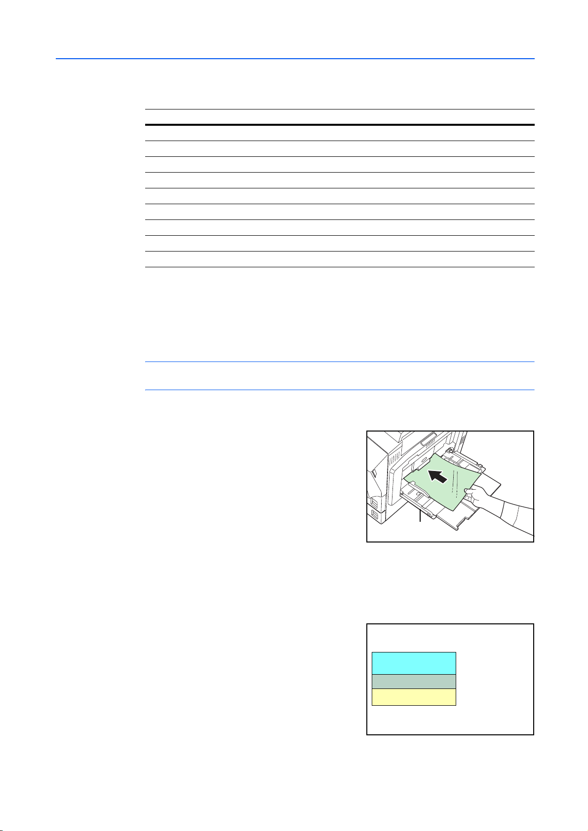
Adhesive label paper must be entirely covered by its
top sheet, with no spaces between the individual
labels. Labels with s paces in between a re liabl e to peel
off, causing serious paper jam problems.
Top sheet (white
bond paper)
Adhesive
Carrier sheet
1-7
Page 14
Handling Paper
Some label paper is manufactured with an extra margin of top sheet around the edge. Do not
remove the extra top sheet from the carrier sheet until after printing is finished.
UnacceptableAcceptable
Top sheet
Carrier sheet
The table below lists the specifications for adhesive label paper.
Item Specification
Weight of top sheet 44 to 74 g/m² (12 to 20 lb/ream)
Composite weight 104 to 151 g/m² (28 to 40 lb/ream)
Thickness of top sheet 0.086 to 0.107 mm (3.9 to 4.2 mils)
Composite thickness 0.115 to 0.145 mm (4.5 to 5.7 mils)
Moisture content 4 to 6% (composite)
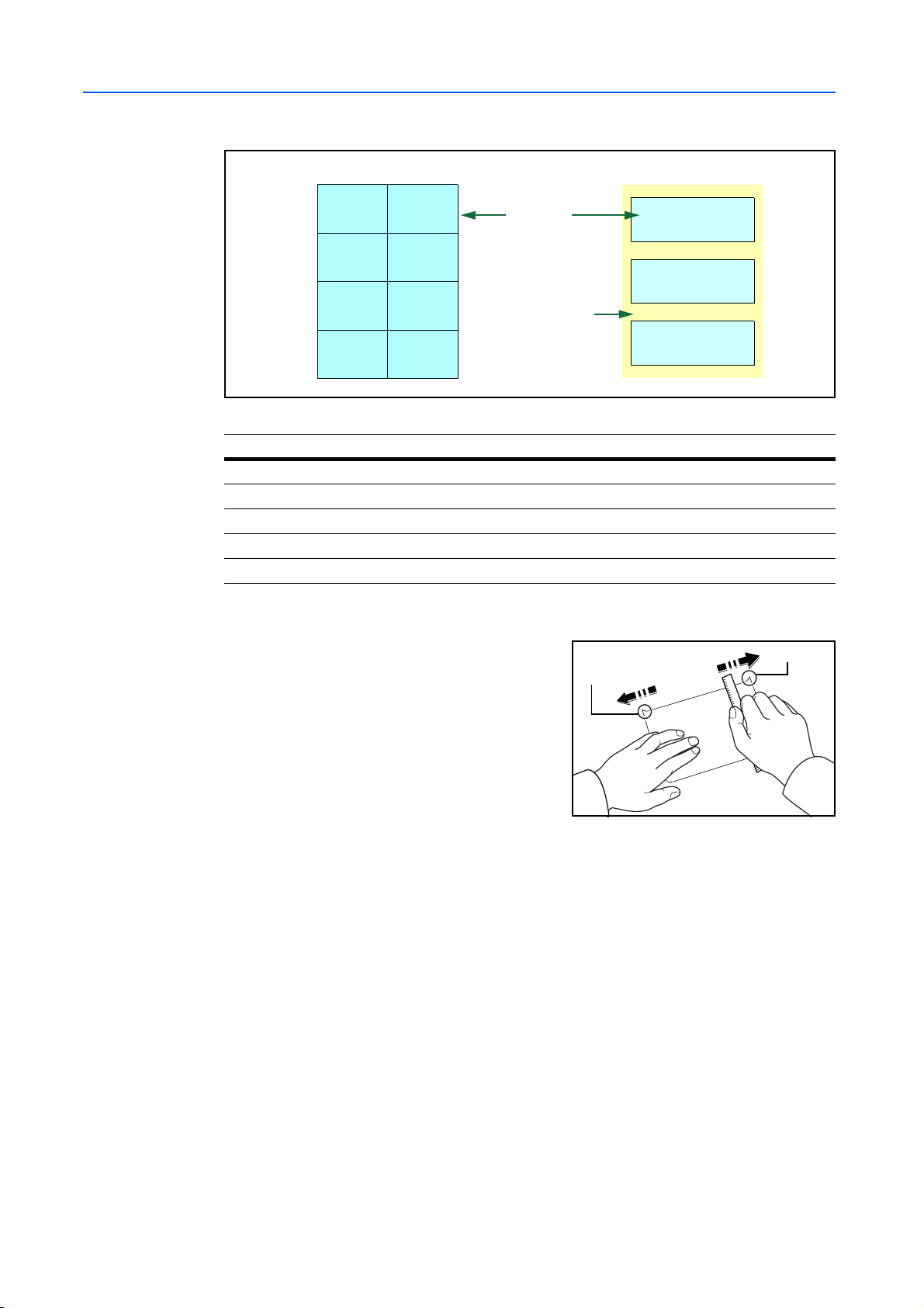
Postcards
Fan the stack of postcard s and ali gn the edg es before
loading them in the MP tray. Make sure the postcards
you are goin g to set are not curled. Feeding curled
postcards may cause paper jams.
Some postcards have rough edges on the back (those
are created when the p aper is cut). In thi s case, put the
postcards on a flat place and rub the edges with, for
example, a ruler to smooth them.
Rough Edge
Rough Edge
Envelopes
Envelopes should be fed in the face-up position, front or right edge first.
Since the composition of an envelope is more complex than that of ordinary paper, it is not always
possible to ensure consistent printing quality over the entire envelope surface.
Normally, envelopes have a diagonal grain direction. Refer to Paper Grain on page 1-6. This
direction can easily cause wrinkles and creases when envelopes pass through the printer. Before
purchasing envelopes, make a test print t o check whether the printer accepts the envel ope.
• Do not use envelopes that have an encapsulated liquid adhesive.
• Avoid a long printing session for envelopes only. Extended envelope printing can cause
premature printer wear.
• If jams occur, try setting a lesser number of envelopes on the MP tray.
1-8
• To avoid jams caused by curled envelopes, stack no more th an 10 printed envelopes on the
output tray.
Page 15
Handling Paper
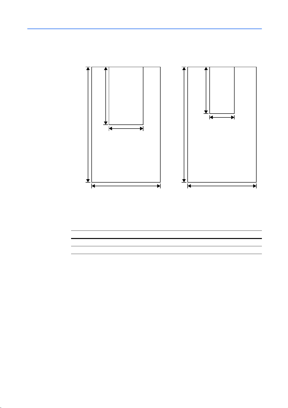
Thick Paper
Fan the stack of pap er and align the ed ges before loa ding them in the MP tray. Some types of paper
have rough edges on the back (thos e are crea ted wh en the p aper i s cut). In this ca se, put th e pa per
on a flat place and rub the edges once or twice with, for example, a ruler to smooth them. Feeding
rough edged paper may cause paper jams.
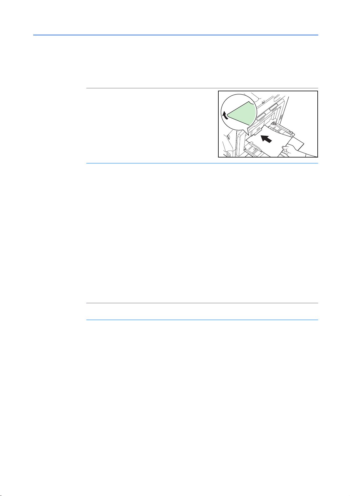
NOTE: If the paper jams even after y ou smooth it out,
load the paper in the MP Tray with the leading edge
raised up a few millimeters as shown in the illustration.
Colored Paper
Colored paper should satisfy the same conditions as white bond paper, Paper Specifications on
page 1-2 In addition, the pigments used in the paper must be able to withstand the heat of fusing
during the printing process (up to 200°C or 392°F).
Preprinted Paper
Preprinted paper should satisfy the same conditions as white bond paper, refer to Paper
Specifications on page 1-2. The preprinted ink must be able to withstand the heat of fusing during
the printing process, and must not be affected by silicone oil.
Do not use paper with any kind of surface treatment, such as the type of paper commonly used for
calendars.
Recycled paper
Select recycled paper that meets the same specifications as the white bond paper except for
whiteness, refer to Paper Specifications on page 1-2.
NOTE: Before purchasing re cycl ed pa per, test a sample on the machine and check that the pr inting
quality is satisfactory.
1-9
Page 16

Handling Paper
Paper Type
The printer is capable of print ing under the opti mu m se ttin g for the type of p ape r being used .
Setting the paper type for the paper source from the printer’s operation panel will cause the printer
to automatically select the paper source and print in the mode best suited to that type of paper.
A different paper type setting can be made for each paper source including the MP tray. Not only
can preset paper types be selected, but it is also possible for you to define and select customized
paper types. Refer to Creating Custom Paper Type on page 2-58. The following types of paper can
be used.
Paper T ype Paper source
MP tray Paper
Cassette
Plain Yes Yes Normal 2 Yes
Transparency Yes No Extra Heavy No
Preprinted Yes Yes Normal 2 Yes
Labels Yes No Heavy 1 No
Bond Yes Yes Normal 3 Yes
Recycled Yes Yes Normal 2 Yes
Vellum Yes Yes Light No
Rough Yes Yes Normal 3 Yes
Letterhead Yes Yes Normal 2 Yes
Color Yes Yes Normal 2 Yes
Prepunched Yes Yes Normal 2 Yes
Envelope Yes N o Heavy 2 No
Cardstock Yes No Heavy 2 No
Coated Yes No Normal 3 No
Thick Yes No Heavy 2 No
High quality Yes Yes Normal 2 Yes
Custom 1 (to 8) *
Yes: Can be stored No: Cannot be stored
Yes Yes Normal 2 Yes
Paper Weight Duplex path
(MP tray available only
in Cassette mode)
1-10
* This is a paper type defined and regi stered by the user. Up to eight types of user setting s m ay be
defined. For details, refer to Creating Custom Paper Type on page 2-58.
Page 17

2 Using the Op e ra ti o n Pan e l
This chapter contains ex planations on the following topics:
• General Information...2-2
• Understanding the Operation Panel...2-3
• Canceling a Printing Job...2-8
• Using the Menu Selection System...2-9
• Status Pages...2-12
• e-MPS...2-15
• Changing the Interface Parameters...2-24
• Making Default Settings...2-30
• Pagination...2-38
• Setting Print Quality...2-41
• Operating the Storage Device...2-42
• Paper Handling...2-50
• Reading Life Counters...2-64
• Other Modes...2-65
2-1
Page 18

Using the Operation Panel
General Information
This chapter provide s the i nforma tio n you n eed to con fig ure the Ec osys pri nter. In general you need
to use the operation p a nel only to make default settings. You can make most changes to the printer
settings using the printer driver through the application software.
NOTE: Changes to printer set tings made using a soft ware appl ication o verride ch anges m ade using
the operation panel.
Y o u can a lso rely on o ther printe r utili ties such as KM-NET for Clie nts if you need to ch ange set tings
that are not available on the printer driver. It will allow remote access to printer settings. Printer
utilities are supplied in the CD-ROM supplied with the printer.
The chapter describes the operation panel in detail, including its menus and the procedures for
changing various printer settings.
2-2
Page 19
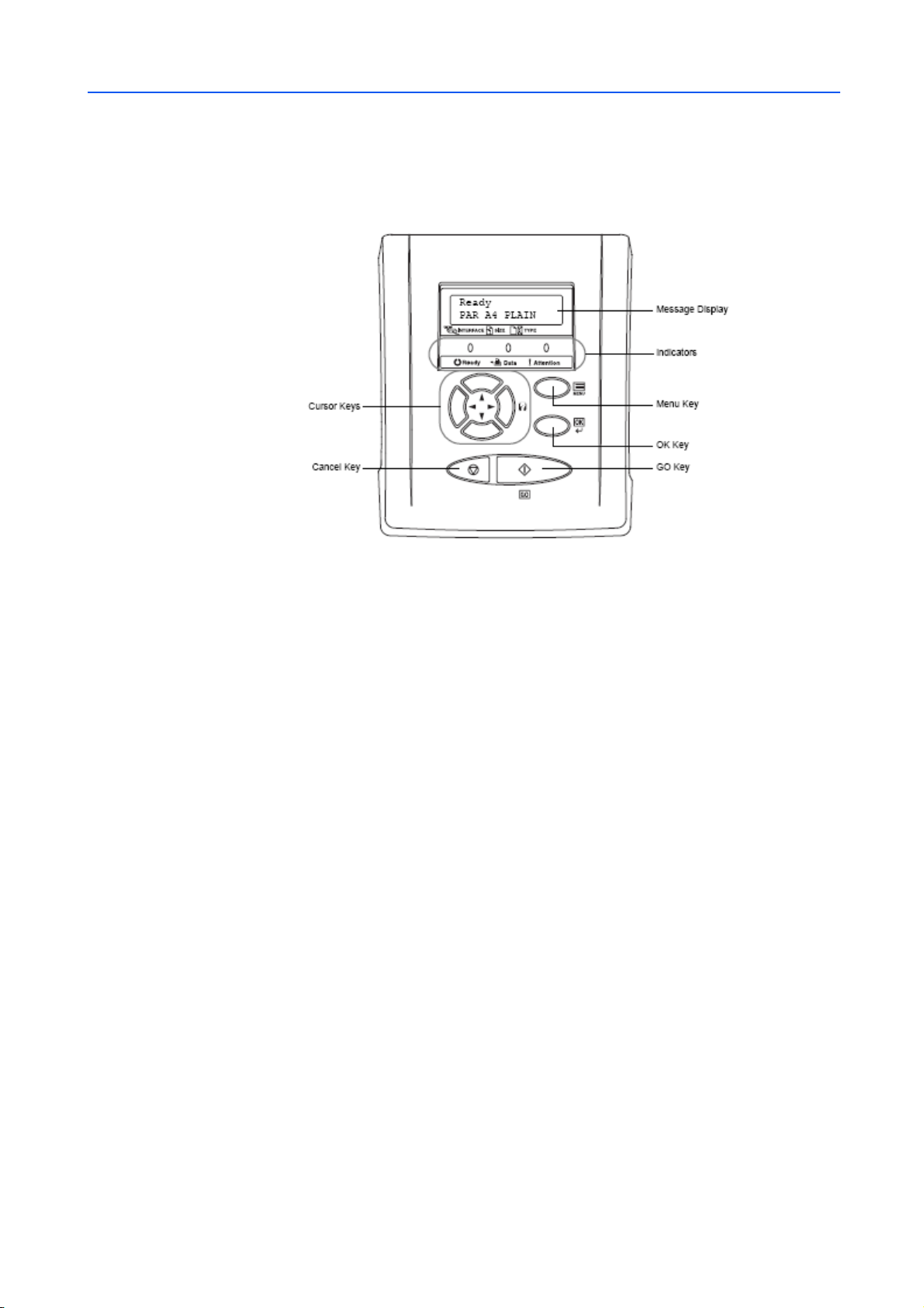
Understanding the Operation Panel
The operation panel on the top of the printer has a 2-line by 16-character liquid crystal display
(LCD), eight keys, and three indicators (LED).
Using the Operation Panel
Message Display
Messages that appear on the display and functions of indicators and keys are explained in this
chapter.
The message display on the operation panel shows:
• Status information, the messages listed below which are displayed during normal operation.
• Error codes, when the printer requires the operator’s attention; as explained in the Operation
Guide.
2-3
Page 20
Using the Operation Panel
Status Information
Message Meaning
Self test The printer is performing self-diagnostics after power-up.
Please wait The printer is warming up and is not ready. When the printer is switched
Please wait
(Adding toner)
Please wait
(Calibrating)
Ready The printer is ready to print.
Processing The printer is receiving data to print. Thi s is also sho wn when the p rinter is
Sleeping The printer is in Auto Sleep. The printer wake s fr om Auto Slee p whe never
Cancelling data The printer is cancelling the data.
Skipping data The printer is skipping the data.
Waiting The printer is waiting for the rest of print job before completing the last
FormFeed TimeOut The printer is printing the last page after a waiting period.
Paper Loading Paper in the paper cassette is being moved. This message may be
Overwriting HDD is being overwritten. Refer to Data Security Kit (D) Operation Guide.
on for the first time, this message will take several minutes.
Toner is currently being replenished. This message may be dis pla ye d
during continuous printing of a large volume of pages which require a
large amount of toner such as with photographs, etc.
The color calibration functi on is bei ng perfo rme d auto ma tic all y as you
powered on the printer.
You can also execute this function manually on the operation panel. For
details, refer to Color Calibration on page 2-79.
reading a memory card, hard disk or RAM disk.
a key on the operation panel and [GO] is pressed, the cover is opened or
closed, or a print job is received. The printer then warms up and goes
on-line. For details on Auto Sleep, refer to Sleep Timer Timeout Time on
page 2-67.
page. Pressing [GO] allows you to obtain t he last page im mediatel y. Refer
to below.
displayed if the paper cassette is inserted again after paper is loaded.
Error codes
Refer to the Troubleshooting section in the Operation Guide.
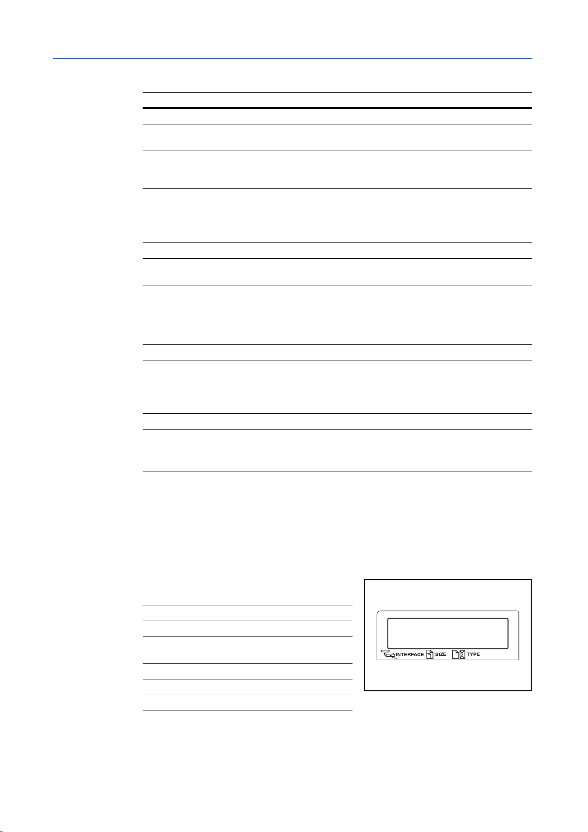
Indicators in Message Display
Interface Indicator (INTERFACE)
The interface indicator show s the int erfa ce tha t is
currently in use:
PAR Parallel interface is in use.
USB USB interface is in use.
SER Serial (RS-232C) interface is in use.
(option)
NET Network int erfa ce is in use.
OPT Network interface is in use. (option)
--- No interface is in use.
Each interface has a timeout time of 30 seconds (factory default) during which the other interface
should wait to receive a print job. Even after a print job has been completed on the interface, you
should wait for this period until the other interface begins printing the job.
Ready
PAR A4 PLAIN
2-4
Page 21

Using the Operation Panel
Paper Size Indicator (SIZE)
This indicator shows:
• While the printer is in standby, the paper size of the current cassette. The default paper
cassette is determined by the operation panel keys. For details, refer to Paper Handlin g on
page 2-50.
• While the printer is printing, the paper size used to format the document to print by the
application software.
The abbreviations used to indicate the paper sizes and their dimensions are as follows:
A3 ISO A3 (297 × 420 mm)
A4 ISO A4 (210 × 297 mm)
A5 ISO A5 (148 × 210 mm)
A6 ISO A6 (105 × 148 mm) *
B4 JIS B4 (257 × 364 mm)
B5 JIS B5 (182 × 257 mm)
B6 JIS B6 (128 × 182 mm) *
LD Ledger (11 × 17 inches)
LT Letter (8-1/2 × 11 inches)
LG Legal (8-1/2 × 14 inches)
MO Envelope Monarch (3-7/8 × 7-1/2 inches) *
DL Envelope DL (110 × 220 mm) *
C4 Envelope C4 (229 × 324mm) *
C5 Envelope C5 (162 × 229mm) *
b5 ISO B5 (176 × 250 mm) *
EX Executive (7-1/4 × 10-1/2 inches) *
#6 Envelope #6 (3-5/8 × 6-1/2 inches) *
#9 Envelope #9 (3-7/8 × 8-7/8 inches) *
10 Envelope #10 (4-1/8 × 9-1/2 inches) *
HA Hagaki (100 × 148mm) *
OH Oufuku Hagaki (148 × 200 mm) *
O2 Oficio II (8-1/2 × 13 inches)
8K 8 kai (273 × 394 mm) *
16K 16 kai (197 × 273 mm) *
ST Statement (5-1/2 × 8-1/2 inches)
FO Folio (210 × 330 mm)
Y2 Yokei 2 (114 × 162 mm) *
Y4 Yokei 4 (105 × 235 mm) *
CU Custom Size (98 × 148 t o 297 × 432mm, 3-3/8 × 5-13/16 to 11-11/16 ×
16-5/8 inches) *
* Only with MP tray feeding
2-5
Page 22
Using the Operation Panel
Paper Type Indicator (TYPE)
This indicator shows the paper type defined for the current paper casette. The paper type can be
manually defined using the operation panel. For more information, refer to Paper Handling on
page 2-50. The following abbreviations are used:
(none) Auto LETTERHD Letterhead
PLAIN Plain paper COLOR Colored paper
TRANSP. Transparency *
PREPRINT Preprinted paper ENVELOPE Envelope *
LABELS Labels * CARDSTOCK Card stock *
BOND Bond paper COATED Coated paper *
RECYCLED Recycled paper THICK Thick paper *
VELLUM Vellum HIGH QLT High-quality paper for color
ROUGH Rough paper CUSTOM 1 (to 8) Custom 1 (to 8)
* Only with MP tray feeding
READY, DATA, and ATTENTION Indicators
PREPUNCH Prepunched paper
printing
Keys
The following indicators light during normal operation and whenever the printer needs attention.
Depending on the status of lighting, each indicator has the following meaning:
Indicator Description
Flashing. In dicates an error that you can resolve. For details, ref er to the
Troubleshooting section in the Operation Guide.
On. Indicates that the printer is ready and on-line. The printer prints the
data it receives.
Off. Indicates that th e printe r is of f-lin e. Dat a ca n be rece ived b ut will no t
be printed until the printer is switched on-line by pressing [GO]. Also,
indicates when printing is automatically stopped due to an error
condition. For details refer to the Troubleshooting section in the
Operation Guide.
Flashing. Indicates that data is being received.
On. Indicates either that dat a received is being proce ssed before p rinting
starts, or that data received is being written to a memory card, hard disk
or RAM disk.
Flashing. Indicates that the printer requires maintenance or is warming
up.
On. Indicates the occurrence of a problem or an error. For details, refer
to the Troubleshooting section in the Operation Guide.
2-6
The operation panel keys are us ed to con fig ure the printer operation. Note that cert a in ke ys have a
secondary function.
NOTE: The printer has a parallel, USB, network, and an optional interface. Configuration of the
printer settings affect only the interface that is currently active (shown by the INTERFACE indicator
on the message display). Refer to Interface Indicator (INTERFACE) on page 2-4.
Page 23

Using the Operation Panel
GO Key
GO switches the printer between on-line and off-line. Use this key to:
• Toggle the printer’s on-line and off-line states. You can temporarily stop the print job by
switching the printer off-line.
• Print and feed out one page when the printer displays Waiting.
• Recover from certain errors.
• Recover from Auto Sleep.
(Cancel) Key
This key is used to:
• Cancel a printing job. (Refer to Canceling a Printing Job on page 2-8.)
• Stop the alarm sound.
• Reset numeric values or cancel a setting procedure while using the menu system.
Menu Key
Menu lets you enter the menu system to change the setup and printing environment of the printer.
Pressing this key during a menu selection will terminate the selection and return the printer to the
normal operation.
Cursor Keys
The four cursor keys are used in the menu system to access an item or enter numeric values.
The arrow key with the question mark ( ) may be pressed when the paper jam message has
appeared on the message display. A help message will then appear to facilitate jam clearing in the
location.
OK Key
This key is used to:
• Finalize settings of numeric values and other selections.
• Set the paper source when Use alternative? is shown in the message display.
NOTE: If you hold down [OK] and press [Menu] when Ready is shown on this printer, the
AdministrationID menu wil l be displayed. This menu is the se tting menu for adm inistrati on under the
Account Management System and is normally not used. Press [Menu] to return to Ready.
2-7
Page 24

Using the Operation Panel
Canceling a Printing Job
While the printer displays Processing, press [Cancel].
1
Print Cancel? appears on the message disp lay foll owed by the interf ace in use. The interfac e is
indicated by one of the following messages:
Parallel
USB
Network
Serial (option serial interface)
Option (option network interface)
Press [OK]. Cancelling data appears on the message display and printing stops after the
2
current page is printed.
2-8
Page 25
Using the Menu Selection System
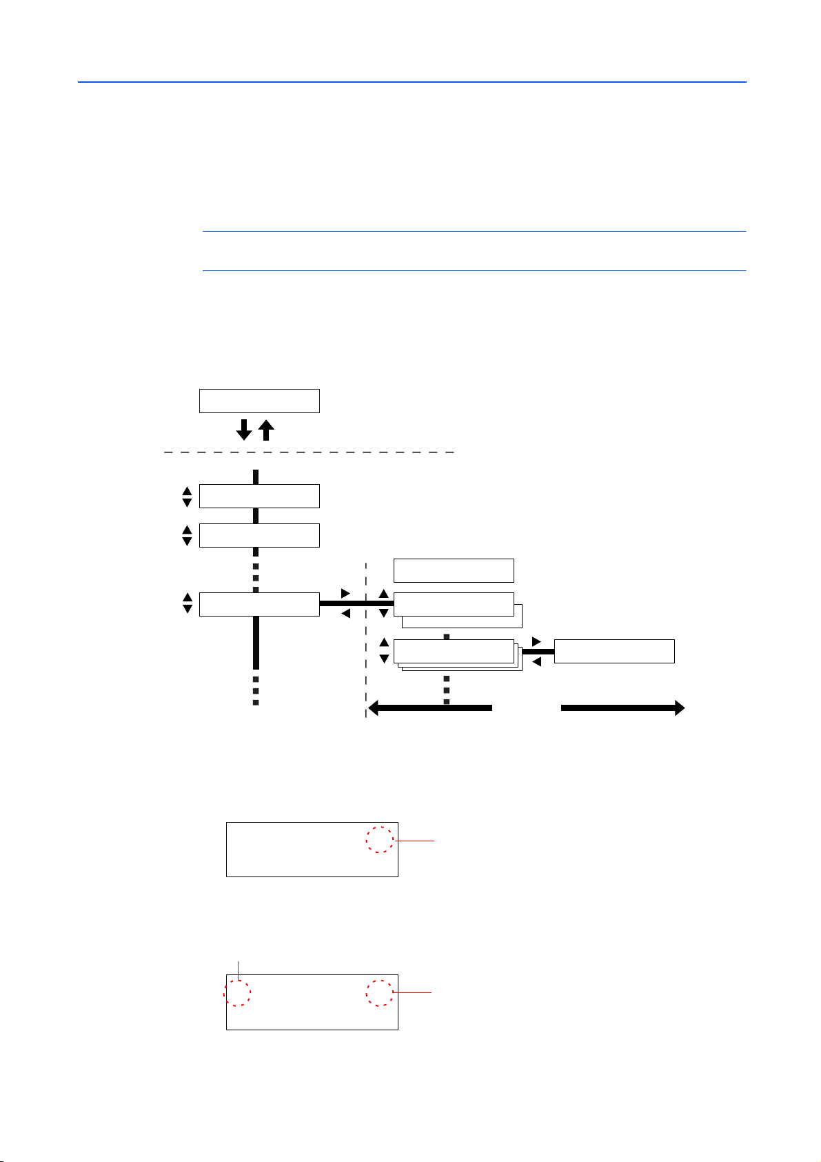
Menu Selection System
This section explain s how to us e t he me nu se lec tion system. [Menu] on the operation panel allows
you to use the menu to configure the printer settings to your specific needs. Settings can be made
when Ready is indicated on the printer message display.
NOTE: Settings that are received from application software and the printer driver will take priority
over settings made in the operation panel.
Entering the Mode Selection Menu
Press [Menu] when Ready is indicated on the printer message display.
The mode selection menu is displayed.
Ready
PAR A4 PLAIN
Press [Menu].
Mode Selection Menu
Using the Operation Panel
Print
Menu Map
Print
Status Page
Paper Handling >
Press [OK].
Press [OK].
>Type Adjust >
>MP Tray Mode
Cassette
>MP Tray Mode
First
>Type Adjust > >>Paper Weight
Press [OK].
Normal 1
Sub-menu
Selecting a Menu
The mode selection menu is hierarchical. Press or to display the desired menu.
If the selected menu has a sub-menu, > is displayed after the menu.
Paper Handling >
Indicates that there is a sub-menu
Press [OK].
Press to move to the sub-menu or to go back.
> is displayed before the sub-menu.
Indicates that this is the sub-menu
>Type Adjust >
Indicates that there is another sub-menu
2-9
Page 26

Using the Operation Panel
Press to move to another sub-menu or to go back.
>> is displayed before the second sub-menu.
Indicates that this is the second sub-menu
>>Paper Weight
Normal 1
Setting a Menu
Select the desired menu and press [OK] to set or change the configuration.
Press or to display the desired item and [OK] to finalize the value or selections set.
Cancelling Menu Selection
If you press [Menu] when a menu is selected, the message display returns to Ready.
Menu System Road Map
The menu map is the hie rarchy diagra m o f the me nu se lectio n sys tem of the prin ter. The menu map
is useful as a reference to guide yourself through the menu selection system.
Printing a Menu Map
The printer prints a full list of the menu selection system — Menu Map. Note that menus shown in
the list may vary depending on which optional units are installed in the printer.
Press [Menu].
1
Press or repeatedly until Print Menu Map appears.
2
Press [OK]. A question mark (?) appears.
3
Press [OK]. The message Processing appears and the printer prints a Menu Map.
4
Print
Menu Map
Print
Menu Map ?
2-10
Page 27
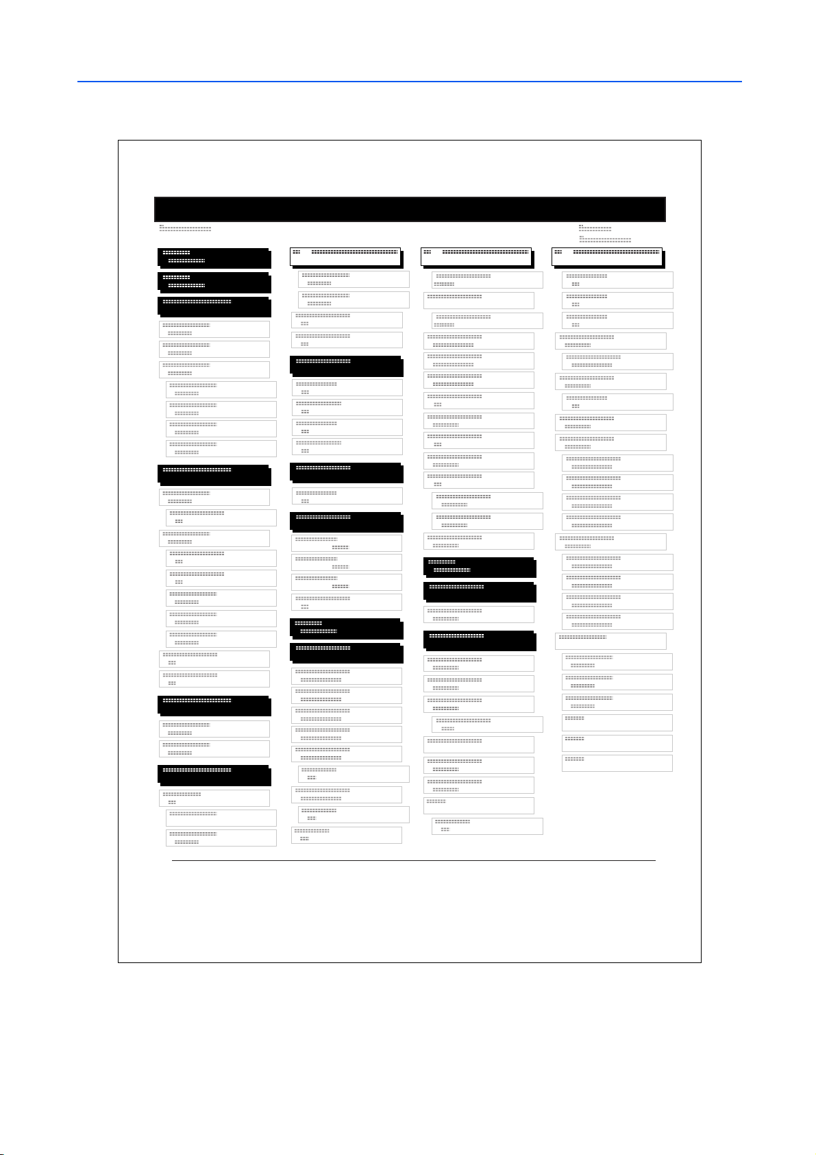
Menu Map Sample
Using the Operation Panel
MENU MAP
2-11
Page 28

Using the Operation Panel
Status Pages
This section explains the procedure for printing the status pages. The status page is a list of
parameters and settings for most basic printer configurations. You may be required to produce a
status page when requesting service to the printer.
Printing a Stat us Page
Y ou can check the printer’s current status, including available memory space and option settings by
printing a status page.
Press [Menu].
1
Press or repeatedly until Print Status Page appears.
2
Press [OK]. A question mark (?) appears.
3
Press [OK] again. The message Processing appears and the printer prints a status page.
4
For a sample status page and its full description, refer to Understanding the Status Page on
page 2-13.
Print
Status Page
Print
Status Page ?
2-12
Page 29
Using the Operation Panel
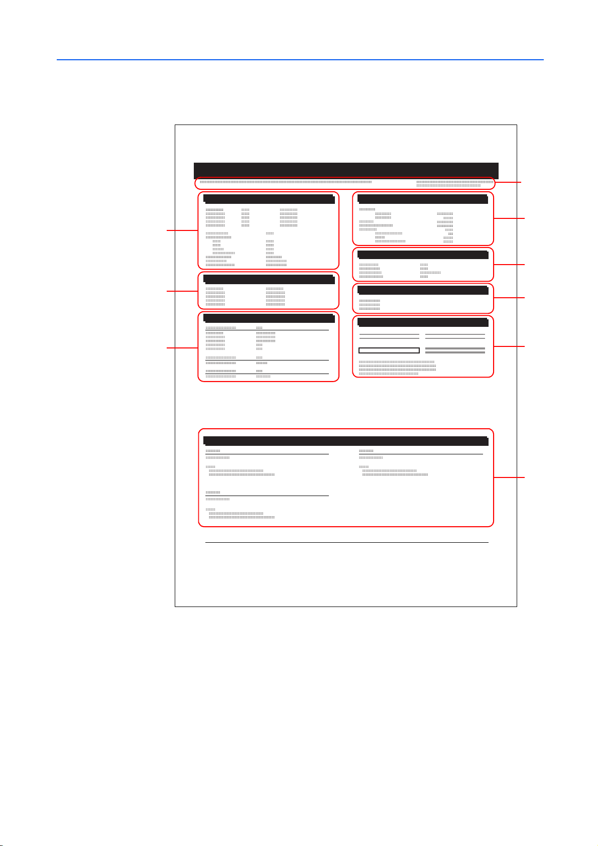
Understanding the Status Page
The numbers in the following diagram refer the items explained below the diagram. The items and
values on the status page may vary depending on the printer’s firmware version.
STATUS PAGE
Hardware Information
2
Memory
1
3
Installed Options
5
Page Information
4
Network Status
6
Interfaces
Emulation
Consumable Status
7
8
9
Firmware Version
1
This item shows the version and release date of the printer firmware.
2-13
Page 30

Using the Operation Panel
Hardware Information
2
This item shows various printer settings for hardware-related items:
Memory
3
This item shows:
Page Information
4
This item shows the page rel ated items:
• MP tray paper size and type
• Paper cassette size and type
•Duplex mode
• Buzzer cont rol
• Host buffer size
• Sleep time timeout time
• Formfeed timeout time
• Standard memory in the printer
• Option memory slot status in kilobytes
• Total memory in the printer
• Current status of the RAM disk
• Tone mode, Normal or Fine
• Number of copies, from 1 to 999
• Total page count
Installed Options
5
This item shows the options installed in the printer:
• Hard disk
•Option ROM
• Memory card
• HDD Security
Network Status
6
This item shows the IP addres s, subne t mask a ddress, and d efault gate way add ress for the ne twork
interface card in the printer.
Emulation
7
This item shows all available emulations of the printer. The PCL 6 emulation is set as default when
the printer is shipped from the factory. The emulations are:
•PCL 6
•KC-GL
• KPDL3
2-14
Consumable Status
8
This item shows the approximate level of remaining toner. When the value is 100, the toner
container is full. The closer to 0, the smaller the amount of remaining toner.
If you use non-original toner kit, the toner gauge measurement will not be indicated correctly.
Interface Information
9
This information shows the emulation and the default font for all interfaces installed in the printer.
Page 31

e-MPS
Using the Operation Panel
e-MPS is an abbreviation for enhanced-Multiple Printing System which implements the following
functions that are available from the printer driver:
• Job Retention
• Job Stor ag e
In either job mode, when print ing a document, the print dat a is trans ferre d from the c om pute r to the
printer then stored on the printer’s hard disk. Since copies of the document are printed using the
stored data, printing is performed faster with less computer spooling time and less network traffic.
NOTE: To use the e-MPS system, an optional hard disk must be installed in the printer. For details,
refer to Hard Disk on page 3-9.
The RAM disk may als o be use d in the Proof-and-Hold and Private Print modes. Refer to Using the
RAM Disk on page 2-48 for details on RAM disk setup.
Job Retention
Job Retention has four modes as summarized below. These modes are selected from the printer
driver through the application software:
Quick Copy Proof-and-Hold Private Print Stored Job
Primary function To later print additional
copies
Start storing by Printer driver Printer driver Printer driver Printer driver
On terminating print
setting from application
software
Retrieved by Operation panel Operation panel Operation panel Operation panel
Default number of
copies printed at
retrieval
Maximum number of
jobs stored*
PIN security No No Yes Yes (if necessary)
Data after printing Stored Stored Deleted Stored
Data at power off Deleted Deleted Deleted Stored
* Jobs in excess will cause the earlier ones to be delet ed.
Prints simultaneously Prints one copy
Same as storing
(can be changed)
32, expandable to 50 32, expandable to 50 Depends on the hard
To proof the first copy
before printing multiple
copies
simultaneously
One less
(can be changed)
T o hold the document in
printer to prevent
unauthorized access
Does not print Does not print
Same as storing
(can be changed)
disk capacity
To electronically store
documents such a s fax
cover pages
One
(can be changed)
Depends on the hard
disk capacity
Job Storage
Job storage stores print jobs either temporarily or permanently, or in virtual mailboxes, as you click
an appropriate radio button on the printer driver when printing from a computer.
Virtual Mailbox
Virtual mailbox is part of Job Storage, which stores print jobs on the hard disk without printing. It
enables you to retrieve jobs later from the operation panel.
Each mailbox may be used by an individual who desires to share the printer in this mode. By
default, each mailbox is numbered from ‘Tray 001,’ ‘Tray 002,’... etc. To ‘post’ a job in one of these
mailboxes, you assign a numbered or named mailbox on the printer driver when printing.
2-15
Page 32

Using the Operation Panel
To retrieve the stored job for printing, refer to Retrieving Jobs from Virtual Mailbox (VMB) on
page 2-19.
NOTE: The virtual mailbox can be used in PCL 6 emulation only.
Using Quick Copy
This mode enables you to prin t the requested number of copie s of a jo b, s imultaneously storing the
job on the hard disk. When additional copies are required, you can reprint the required number of
copies from the printer operation p an el.
The default number of print jobs that can be stored on the hard disk is 32. This value can be
increased to up to 50 from the e-MPS Configuration menu. For details, refer to Changing the
Maximum Number of Quick Copy/Proof-and-Hold Jobs on page 2-21. When the number of jobs
reaches the limi t, the ol dest job w ill b e over writte n by the new one . When th e printe r is turn ed of f , all
stored jobs will be deleted.
Printing Additional Copies using Quick Copy
Press [Menu].
1
Press or repeatedly until e-MPS > appears.
2
e-MPS >
Press .
3
Press or repeatedly until >Quick Copy appears followed
4
by the user name (Harold, in this example). The user name is
assigned when printing using the printer driver.
Press [OK]. A blinking question m ark (?) appears before the user
5
name.
Press or to display the desired user name, Arlen, in this
6
example.
Press [OK]. The job name entered in the printer driver (Report,
7
in this example) appear with a blinking question mark (?) before
the letters.
Press or to scroll to the desired job title.
8
Press [OK]. The number of copies to be printed can be set. To
9
increase the copy count, press ; to decrease the copy count,
press .
>Quick Co py
Harold
>Quick Copy
?Harold
>Quick Copy
?Arlen
>Arlen
?Report
>Report
Copies 001
2-16
Press [OK] to finalize the copy count. The printer prints the specified number of copies for the job.
10
Page 33

Deleting a Quick Copy Job
Follow steps 1 through 8 in the above section to display the title of the job to be deleted.
1
When the title of the job to be deleted is displayed, e.g. Report,
2
press [OK]. The cursor below the copy count starts to blink.
Press repeatedly until Delete appears below the title.
3
Press [OK]. The stored quick copy job is deleted.
4
Using Proof-and-Hold
When you print multiple copies, this mode first prints one copy so that you can proof it before
continuing to print the remaining copies. Since you can proof the printouts before printing the
remaining copies, paper waste can be reduced.
The printer prints one copy and, at the same time, saves the print job on the hard disk/RAM disk.
You can also change the number of copies when resuming printing from the operation panel.
Using the Operation Panel
>Report
Copies 001
>Report
Delete
When the printer is turned off, all stored jobs will be deleted.
Printing Remaining Copies of a Proof and Hold Job
Printing a Proof-and-Hold job on the operation panel is similar to printing a quick copy job. Refer to
Printing Additional Copies using Quick Copy on page 2-16.
Printing a Private Print/Stored Job
In private printing, you can specify that a job is not printed until you release the job from the
operation panel. When sending the job from the application software, specify a 4-digit access code
in the printer driver. The job is released for printing by entering the access code on the operation
panel ensuring confidentiality of the print job.
In the stored job mode, access codes are not mandatory, but can be set on the printer driver if
printing with PIN security is requir ed. Then, the access code must be entered on the operat ion panel
to print a stored job. Print data will be stored in the hard disk/RAM disk after printing.
Releasing a Private/Stored Job
Press [Menu].
1
Press or repeatedly until e-MPS > appears.
2
e-MPS >
Press .
3
Press or repeatedly until >Private/Stored appears. The
4
name entered in the printer driver (Harold, in this example) also
appears.
>Private/Stored
Harold
2-17
Page 34

Using the Operation Panel
Press [OK]. A blinking question m ark (?) appears before the user
5
name.
Press or to display the desired user name (Arlen, in this
6
example).
Press [OK]. The user name and the job name (Agenda, in this
7
example) entered in the printer driver appear with a blinking
question mark (?).
Press or to display the desired job tit le.
8
Press [OK]. The ID input line appears. Enter the four-digit acces s
9
code entered in the printer driver and press [OK].
To enter the ID, press or to move the cursor to the numbe r to
be changed and then enter the correct number by pressing or
.
>Private/Stored
?Harold
>Private/Stored
?Arlen
>Arlen
?Agenda
>Agenda
ID 0000
You can set the number of copies to be printed. To increase the
10
copy count, press ; to decrease the copy count, press .
>Agenda
Copies 001
Press [OK] to finalize the copy count. The printer prints the specified number of copies for the job.
11
Deleting a Private/Stored Job
You can individually delete stored jobs by performing the following procedure. Jobs saved using
Private Print will be automatically deleted if you turn the power off after printing, but jobs saved
using Stored Job will not be deleted automatically.
Follow steps 1 through 8 in the above section.
1
When the title of the job to be pri nted is dis played (Agenda, in this
2
example), press [OK]. Enter the four-digit access code entere d in
the printer driver and press [OK].
Press repeatedly until Delete appears for the number of
3
copies.
Press [OK]. The private job is deleted.
4
>Agenda
Copies 001
>Agenda
Delete
2-18
Printing a Code Job
To print a code job, ensure that the KM-NET for Clients is installed on the computer. The KM-NET
for Clients is provided on the Software Library CD-ROM.
For details, refer to the KM-NET for Clients Operation Guide.
Page 35

Using the Operation Panel
Printing a List of Code Jobs
If you select Permanent Job Storage on the printer driver, you can print a List of Code Jobs using
the operation panel.
Press [Menu].
1
Press or repeatedly until e-MPS > appears.
2
Press .
3
Press or repeatedly until >Print Code Job List
4
appears.
Press [OK]. A question mark (?) appears.
5
e-MPS >
>Print
Code Job List
>Print
Code Job List?
Press [OK] again. The printer prints a Code Job list as shown below.
6
PERMANENT CODE JOB LIST
Retrieving Jobs from Virtual Mailbox (VMB)
Press [Menu].
1
Press or repeatedly until e-MPS > appears.
2
e-MPS >
Press .
3
Press or repeatedl y until >Print VMB Data appears. The
4
virtual mailbox number will also appear.
>Print VM B Data
Tray001:
2-19
Page 36

Using the Operation Panel
If you have named the virtual mailbox with an alias, the alias
(Richard, in this example) will follow the number:
>Print VM B Data
Tray001:Richard
Press [OK]. A blinking question mark (?) appears.
5
>Print VM B Data
Tray001?Richard
Press [OK]. The document in the mailbox is printed and automatically deleted from the mailbox.
6
Printing a List of VMB
A Virtual Mailbox list includes the jobs currently stored in the mailboxes.
Press [Menu].
1
Press or repeatedly until e-MPS > appears.
2
3
Press .
e-MPS >
Press or repeatedly until >List of VMB appears.
4
>Print
VMB List
Press [OK]. A question mark (?) appears.
5
>Print
VMB List ?
Press [OK] again. The printer pri nt s a lis t of jobs currently posted in th e vi rtua l m ail box es as show n
6
in the following illustration.
VIRTUAL MAIL BOX LIST
2-20
Page 37

Changing e-MPS Configuration
You can change the following parameters for e-MPS operation:
• Maximum number of Quick Copy/Proof-and-Hold jobs
• Maximum space assigned to temporary code jobs
• Maximum space assigned to permanent code jobs
• Maximum space assigned to virtual mailboxes
NOTE: The total amount of storage areas specified must not exceed the total size of the hard disk.
Changing the Maximum Number of Quick Copy/Proof-and-Hold Jobs
This changes the m axi mum number of Quic k Copy /Proof-and-Hold jobs f rom 0 t o 50. The default is
32.
Press [Menu].
1
Press or repeatedly until e-MPS > appears.
2
Using the Operation Panel
e-MPS >
Press .
3
Press or repeatedly until >e-MPS Configuration >
4
appears.
>e-MPS >
Configur ation
Press .
5
Press or repeatedly until >>Quick Copy appears.
6
>>Quick Cop y
32
Press [OK]. A blinking cursor (_) appears.
7
>>Quick Cop y
32
Press or to increase or decrease the value at the blinking cursor. The value can be set
8
between 0 and 50. Use and to move the cursor right and left.
When the desired maximum number of jobs is set, press [OK].
9
Press [Menu]. The display returns to Ready.
10
Maximum Space Assigned to Temporary Code Jobs
This changes the hard disk space that holds temporary code jobs. You can change the maximum
space from 0 to 999 9 (m egabytes). The actual m axim um s ize de pen ds on the size of free hard dis k
space. The default size is 1/6 of the total hard disk space, rounded off in units of 50 MB. For
example, if the total hard disk space is 10 GB, the default size is 1550MB.
Press [Menu].
1
2-21
Page 38

Using the Operation Panel
Press or repeatedly until e-MPS > appears.
2
Press .
3
Press or repeatedly until >e-MPS Configuration >
4
appears.
Press .
5
Press or repeatedly until >>Temp. Code JOB Size
6
appears.
To change the maximum disk space, press [OK]. A blinking
7
cursor (_) appears.
e-MPS >
>e-MPS >
Configur ation
>>Temp. Code JOB
Size 1550MB
>>Temp. Code JOB
Size 1550
MB
Press or to increase or decrease, respectively, the value at the blinking cursor. Use and
8
to move the cursor right and left.
When the desired size is displayed, press [OK].
9
Press [Menu]. The display returns to Ready.
10
Maximum Space Assigned to Permanent Code Jobs
This changes the hard disk space that holds permanent code jobs. You can change the maximum
space from 0 to 9 999 (megabytes). The actual maximum size dep ends on the size of free hard disk
space. The default size is 1/6 of the total hard disk spac e, rounded off in units of 50 MB. For
example, if the total hard disk space is 10 GB, the default size is 1550 MB.
Press [Menu].
1
Press or and select e-MPS >.
2
Press .
3
Press or and select >e-MPS Configuration >.
4
e-MPS >
>e-MPS >
Configur ation
2-22
Press .
5
Press or and select >>Perm. Code JOB Size.
6
>>Perm. Code JOB
Size 1550MB
Page 39

Using the Operation Panel
Press [OK], the message display shows a blinking cursor (_).
7
>>Perm. Code JOB
Size 1550
Press or to increase or decrease, respectively, the value at the blinking cursor. Use and
8
to move the cursor right and left.
When the desired size is displayed, press [OK].
9
Press [Menu] and the display returns to Ready.
10
Maximum Space Assigned to Vi rtual Mailboxes (VMB)
This changes the h ard disk s pac e for vi rtual mai lboxe s. You can change the maxim um sp a ce from 0
to 9999 (megabytes). The actual maximum size depends on the size of free hard disk space. The
default size is 1/6 of the tot al hard disk sp ace, roun ded off in un its of 50MB. For example, if the total
hard disk space is 10 GB, the default size is 1550 MB.
Press [Menu].
1
Press or and select e-MPS >.
2
e-MPS >
MB
Press .
3
Press or and select >e-MPS Configuration >.
4
>e-MPS >
Configur ation
Press .
5
Press or and select >>VMB Size.
6
>>VMB Size
1550MB
To change the maximum size, press [OK]. The message display
7
shows a blinking cursor (_).
>>VMB Size
1550
Press or to increase or decrease, respectively, the value at the blinking cursor. Use and
8
to move the cursor right and left.
When the desired size is displayed, press [OK].
9
Press [Menu] to exit the menu selection.
10
MB
2-23
Page 40

Using the Operation Panel
Changing the Interface Parameters
This printer is equipped with a parallel interface, a USB interface and a network interface. An
optional serial interface and a network interface can be installed. Various printing environment
parameters such as the default emulation can be changed independently on different interfaces by
using the printer’s menu selection system. Select the interface to apply the changes in the
procedure described below.
NOTE: This interface selection described below does not select the interface from which data will
be received. The printer automatically selects the interface.
Changing Parallel Interface Mode
The parallel interface supports a bi-directional/high-speed mode according to IEEE standards.
Normally, this interface is used under the default se ttin g Auto. For detai ls, refer to Pa rallel I nterfac e
on page 4-3. After setting the interface, be sure to reset the printer or turn the power off at least
once. The new setting will be enabled thereafter. You can select from the following:
• Auto (default)
•Normal
• High speed
• Nibble (high)
Press [Menu].
1
Press or repeatedly until Interface > appears.
2
If the interface is other than parallel, press [OK]. A blinking
3
question mark (?) appears.
Interface
? Serial
Press or repeatedly until Parallel appears.
4
Interface
? Parallel
Press [OK] again. The question mark disappears.
5
To change the parallel interf ace mode, press . The current communication mode appears.
6
To change the communication mode, press [OK]. A blinking
7
question mark (?) appears.
>Parallel I/F
? Nibble (high)
Press or to scroll through the following communication modes:
8
Auto
Normal
High speed
Nibble (high)
2-24
When the desired communication mode is displayed, press [OK].
9
Press [Menu] to exit the menu selection.
10
Page 41

Changing Serial Interface Parameters
NOTE: This section applies to the printer having the optional serial interface board kit (IB-11)
installed.
You can confirm or change the serial interface parameters including baud rate, data bits, stop bits,
parity, and protocol. These parameters must match those of the computer’s serial interface.
Press [Menu].
1
Press or repeatedly until Interface > appears.
2
If the interface is othe r than serial, press [OK]. A blinkin g question
3
mark (?) appears.
Press or repeatedly until Serial appears.
4
Using the Operation Panel
Interface
? Parallel
Interface
? Serial
Press [OK] again.
5
Press . One of the following serial parameters is indicated (Baud rate for example).
6
Pressing or toggles through the serial parameters as follows. To change the serial parameter,
press [OK]. Use or to change the value or selection.
Range
>Baud Rate
1200, 2400, 4800, 9600 (Default), 19200, 38400, 57600,
115200
9600
>Data Bits
7 or 8 (Default)
8
>Stop Bits
1 (Default) or 2
1
>Parity
None (Default), Odd, Even, or Ignore
None
>Protocol
DTR(pos.)&XON
DTR(pos.)& Xon (Default), DTR(positive),
DTR(negative), XON/XOFF, or ETX/ACK
2-25
Page 42

Using the Operation Panel
For example, to change baud rate from 9600 to 115200, display
the baud rate menu following the above procedure. When the
display shows baud rate, 9600 (bps), press [OK]. A blinking
question mark (?) appears.
Press or to scroll through values. When 115200 is displayed, press [OK]. Press [Menu] to
7
exit the menu selection.
NOTE: Some computers may not be able to handle a baud rate of 115200 bps. If you set the baud
rate to 115200 and encounter communication problems, select a lower baud rate.
Changing Network Interface Parameters
This printer supports TCP/IP, NetWare and AppleTalk protocols. In addition, you can install the
optional network interface card in the option interface slot.
Using the operation panel, you can:
• Activate or deactivate TCP/IP, NetWare, and AppleTalk
• Activate or deactivate DHCP
• Enter IP address, subnet mask address, and default gateway address
• Determine whether to print a network status page when the printer is turned on
>Baud Rate
? 9600
Press [Menu].
1
Press or repeatedly until Interface > appears.
2
If the current interface is other than Network, press [OK]. A
3
blinking question mark (?) appears.
If the optional network interface card is installed in the printer,
Option will be displayed. The setting procedure is basically the
same even in this case.
Press or repeatedly until Network appears.
4
Press [OK] again.
5
Interface >
? Parallel
Interface >
? Network
2-26
Page 43

Using the Operation Panel
Press . One of the follo wing men us is indi cated . To change settings for the item , press [OK]. Use
6
or to change the value or selection.
Set this item to On when you connect to a network using NetWare.
In submenu (>), frame mode can be selected from Auto, 802.3,
Ethernet II, SNAP, and 802.2.
>NetWare >
On
Set this item to On when you connect to a network using TCP/IP.
Submenu (>) has items incl udi ng DHCP, BOOTP, IP address,
subnet mask address, and gateway address. To resolve IP address
for the network card, refer to Resolving IP Address on page 2-27.
AppleTalk must be activated (On) for networking with Macintosh
computers.
When the item is set to On, the printer prints out a network status
page when it prints the printer status. refer to Printing a Network
Interface Status Page on page 2-28.
Activate the appropriat e prot oc ol th at is requ ired to connect the printer to the network . To activate a
7
protocol, display the protocol, press [OK], pres s or to ch ange from Off to On, and press [OK].
Press [Menu]. The di splay retu rns to Ready. You can print a network status page to confirm that the
8
IP address, subnet mask address, and the gateway address have been properly set. To print a
network status page, refer to Printing a Network Interface Status Page on page 2-28.
Resolving IP Address
To connect the printer to the network using TCP/IP protocol, you must set the IP address on the
printer. The IP address must be unique to the printer and should be obtained from your network
administrator.
>TCP/IP >
On
>AppleTalk
Off
>Network Status
Page Off
Activate TCP/IP protocol in the manner described above.
1
>TCP/IP >
On
2-27
Page 44

Using the Operation Panel
Enter the submenu by pressing . Each time you press or ,
2
the selection change s.
>>DHCP
On
>>BOOTP
On
>>IP Address
000.000.000.000
>>Subnet Ma sk
000.000.000.000
>>Gateway
000.000.000.000
When >>IP Address is di splay ed, pres s [OK]. A blink ing cu rsor
3
(_) appears at the last digit.
Press or to increase or decrease, respectively, the value at the blinking cursor. Use and
4
to move the cursor right and left.
When the IP address is entered, press [OK].
5
Press or to move to Subnet Mask. Perform the same procedure to complete entering the
6
subnet mask address.
Then, press or to move to Gateway. Perform the same procedure to complete entering the
7
gateway address.
Press [Menu]. The display returns to Ready. You can print a network status page to confirm tha t the
8
IP address, subnet mask address, and the gateway address have been properly set. To print a
network status page, refer to Printing a Network Interface Status Page on page 2-28.
Printing a Network Interface Status Page
You can have your printer print out a network status page when the printer prints the status page.
The network status page shows the network addresse s, and oth er inform at ion under various
network protocols about the netw o rk inte rfac e card . The defa ult se tting is Off (print disable).
>>IP Address
000.000.000.000
2-28
NOTE: Printing out a network interface status page may not be possible with the optional network
interface card. For details, refer to the manual for the network interface.
Press [Menu].
1
Press or repeatedly until Interface > appears.
2
Page 45

If the current interface is other than Network, press [OK]. A
3
blinking question mark (?) appears.
Press or repeatedly until Network appears. Press [OK].
4
Press and then press or repeatedly until the display
5
shows >Network Status Page.
Press [OK]. A blinking question mark (?) appears.
6
Press or to select On.
7
Using the Operation Panel
Interface
? Parallel
Interface
? Network
>Network St atus
Page O ff
>Network Status
Page ? Of f
>Network Status
Page ? On
Press [OK] again.
8
Press [Menu]. The display returns to Ready.
9
NETWORK STATUS PAGE
2-29
Page 46

Using the Operation Panel
Making Default Settings
Using the operation panel, you can set the default for the following items.
Default Emulation
You can change the emulation mode and character code set for the current interface.
The printer can autom atic al ly cha nge the e mu lati on mod e ac co rding to the print job that is recei ve d
from the computer. To do this, select KPDL (AUTO) in the following procedure.
Press [Menu].
1
Press or repeatedly until Emulation > appears on the message display. One of the
2
emulation modes appears, indicating the emulation currently in use.
PCL 6 (default)
KC-GL
KPDL
KPDL (AUTO)
To change the de fault emulation, press [OK]. A blinking question
mark (?) appears.
Emulation
?PCL 6
Press or repeatedly until the desired emulation mode is displayed.
3
Press [OK].
4
Press [Menu]. The display returns to Ready.
5
Alternative Emulation for KPDL Emulation
KPDL is Kyocera’s implementation of the PostScript language. The KPDL (AUTO) emulation
enables the printer to automatically change the emulation mode according to the data received
when printing.
In addition to KPDL (AUTO) emulation, you can use the operation panel to set another emulation
mode that is used very often. The default setting is PCL 6.
Press [Menu].
1
Press or repeatedly until Emulation > appears.
2
Press [OK]. A blinking question mark (?) appears.
3
Press or repeatedly until KPDL (AUTO) appears.
4
Emulation
?PCL 6
Emulation
?KPDL (AUTO)
2-30
Press [OK].
5
Press . When >Alt. Emulation is displayed, press or . The names of alternative
6
emulations appear — PCL 6 or KC-GL.
Page 47

Press [OK]. A blinking question mark (?) appears.
7
Press or repeatedly until the desired alternative emulation appears.
8
Press [OK].
9
Press [Menu]. The message display returns to Ready.
10
Printing KPDL Errors
The printer can print error descriptions when printing error occurs during KPDL emulation. The
default is Off — the printer does not print KPDL errors.
Press [Menu].
1
Press or repeatedly until Emulation > appears.
2
Press [OK]. A blinking question mark (?) appears.
3
Using the Operation Panel
>Alt. Emulation
? PCL 6
Emulation
?PCL 6
Select KPDL or KPDL (AUTO) using or .
4
Press [OK].
5
Press . Press or until >Print KPDL Errs (errors)
6
appears.
Press [OK]. A blinking question mark (?) appears.
7
Select On using or . Press [OK].
8
Press [Menu]. The display returns to Ready.
9
KC-GL Pen Width and Color
The KC-GL emulation mod e enables you to set the pe n w idths in dots, indi vidual pen colors for p en
numbers 1 to 8, and the KC-GL page size.
Emulation
?KPDL
>Print KP DL Errs
Off
>Print KP DL Errs
? Off
Press [Menu].
1
Press or repeatedly until Emulation > appears.
2
If the current emulation is other than KC-GL, press [OK]. A blinking question mark (?) appears.
3
2-31
Page 48

Using the Operation Panel
Select KC-GL using or .
4
Press [OK].
5
Press . To change th e pen wi dth and /or pen co lor , press [OK]. A
6
blinking question mark (?) appears.
Press or repeatedly until the desired pen number of 1 to 8 appears.
7
Press [OK].
8
To change the pe n width, press , then press [OK]. A blinking
9
cursor appears at the width value.
Press or repeatedly until the desired pen width in dots (00 to 99) appears.
10
Emulation
?KC-GL
>KC-GL Pen
Adjust ? Pen ( 1)
>>Pen(1) Wi dth
02
dot(s)
Press [OK].
11
To set the pen color, press or .
12
Press [OK]. A blinking question mark (?) appears.
13
>>Pen(1) Co lor
? Black
Press or repeatedly until the desired pen color (Black, Red, Green, Yellow, Blue,
14
Magenta, Cyan, White) appears.
Press [OK].
15
To set the KC-GL page size, press , then press or until >KC-GL Page set appears.
16
Press [OK]. A blinking question mark (?) appears.
17
>KC-GL Pa ge Set
? [A2]
Press or repeatedly until the desired page size (A2, A1, A0, B3, B2, B1, B0, and SPSZ)
18
appears. When selecting SPSZ, printing will be done with the paper size specified by the
PRESCRIBE SPSZ command.
Press [OK].
19
2-32
Press [Menu]. The display returns to Ready.
20
Page 49

Default Font
Using the Operation Panel
You can select the default font for the current interface. The default font can be one of the internal
fonts or a font that is downloaded to the printer memory or stored in a memory card, hard disk or
option ROM.
In this menu, you can also set the type and pitch for Courier and Letter Gothic; as well as to print a
font list.
Press [Menu].
1
Press or repeatedly until Font > appears.
2
Font >
Press . Press or until >Font Select > appears.
3
>Font Select >
Internal
To select an internal font, make sure that Internal is displayed
4
and press . The display chan ges. If Internal is not disp layed ,
press [OK], then press or until it appears.
>> I000
To select an optional font, press [OK] while >Font Select > is
displayed. Press or repeatedly until Option appears and
then press [OK]. Press next to display the font selection shown above. You can perform this
operation only when optional fonts are installed in the printer.
The letter before the number indicates the location of the font, as shown below:
I Internal font
S Soft (downloaded) font
M Fonts in optional memory card
H Fonts in RAM disk or optional hard disk
O Fonts in optional ROM (API)
Press [OK]. A blinking question mark (?) appears.
5
>>?I000
Press or repeatedly until the desired font number appears. For font numbers of the internal
6
fonts, refer to Printing Lists of Fonts on page 2-36.
When the desired font is displayed, press [OK].
7
Press [Menu]. The display returns to Ready.
8
Selecting Regular or Dark Courier/Letter Gothic
Courier or Letter Gothic font thickness can be selected as Regular or Dark. In the procedure
below, it is assumed that Courier is selected. The procedure is the same for Letter Gothic.
Press [Menu].
1
Press or repeatedly until Font > appears.
2
Font >
2-33
Page 50

Using the Operation Panel
Press . Press or until >Font Select > appears.
3
Make sure that Internal is displayed and press .
4
Press or repeatedly until >>Courier appears. If you are
5
selecting the thickness of the Letter Gothic font, choose >>
Letter Gothic here instead.
Press [OK]. A blinking question mark (?) appears.
6
Select Regular or Dark using or .
7
Press [OK].
8
Press [Menu]. The display returns to Ready.
9
>Font Select >
Internal
>>Courier
Regular
>>Courier
? Regular
Changing the Default Font Size
You can change the size of the default font. If you selected a proportional font, the character size
can also be changed.
Press [Menu].
1
Press or repeatedly until Font > appears.
2
Press . Press or until >Font Select > appears.
3
Make sure that Internal is displayed and press .
4
Press or repeatedly until >>Size appears.
5
Press [OK]. A blinking cursor (_) appears.
6
Font >
>Font Select >
Internal
>>Size
012.00 point(s)
>>Size
012.00
point(s)
2-34
Press or to increase or decrease the value at the blinking cursor. The font size can be set
7
between 4 and 999.75 points, in 0.25-point increments. Use or to move the cursor right and
left.
When the desired size is displayed, press [OK].
8
Press [Menu]. The display returns to Ready.
9
Page 51

Using the Operation Panel
Character Pitch for Courier/Letter Gothic
You can set the character pitch for fixed fonts when the default font is Courier or Letter Gothic.
Press [Menu].
1
Press or repeatedly until Font > appears.
2
Press . Press or until >Font Select > appears.
3
Make sure that Internal is displayed and press .
4
Press or repeatedly until >>Pitch appears.
5
Press [OK]. A blinking cursor (_) appears.
6
Font >
>Font Select >
Internal
>>Pitch
10 .00 cpi
>>Pitch
10 .00
cpi
Press or to increase or decrease the value at the blinking cursor. The character pitch can be
7
set between 0.44 and 9 9.99 characters p er inch, in 0.01 ch aracter-per-inch i ncrements. U se or
to move the cursor right and left.
When the desired size is displayed, press [OK].
8
Press [Menu]. The display returns to Ready.
9
Setting the Code Set
You can change the character code set. Available character code sets vary depending on the
current font. (The default is IBM PC-8.)
Press [Menu].
1
Press or repeatedly until Font > appears.
2
Press .
3
Press or repeatedly until >Code Set appears.
4
Font >
>Code Set
IBM PC-8
Press [OK]. A blinking question mark (?) appears.
5
>Code Set
?IBM PC-8
2-35
Page 52

Using the Operation Panel
Press or until the desired character code set appears.
6
Press [OK].
7
Press [Menu]. The display returns to Ready.
8
Printing Lists of Fonts
To help you decide in selecti ng a font, you can printout lists of the i nternal fonts or the op tional fonts
including downloaded fonts.
Press [Menu].
1
Press or repeatedly until Font > appears.
2
Press .
3
Press or repeatedly until >Print Internal Fonts List
4
or >Print Option Fonts List appears.
Font >
>Print In ternal
Fonts List
Press [OK]. A question mark (?) appears.
5
>Print In ternal
Fonts List?
Press [OK] again. Processing appears, then Ready. The printer prints out a list of fonts with a
6
sample and font ID (number) for each of them. Sample lists of fonts are shown in the following
illustration.
2-36
Page 53

Samples of Fonts List
Using the Operation Panel
Internal Scalable and Bitmapped Fonts List
Font Name Scalable/Bitmap Password Selection [FSET] Font ID
Internal Scalable and Bitmapped Fonts List
Font Name Scalable/Bitmap Password Selection [FSET] Font ID
PRESCRIBE
PRESCRIBE
2-37
Page 54

Using the Operation Panel
Pagination
In Page Set menus, you can set the number of copies, page orientation, and other settings
regarding pagination.
Number of Copies
Y ou c an set th e number o f copies of each p age to be printed for the cur rent int erface. The number o f
copies can be set between 1 and 999.
Press [Menu].
1
Press or repeatedly until Page Set > appears .
2
Press .
3
Press or repeatedly until >Copies appears.
4
Page Set >
>Copies
001
5
6
7
8
Print Orientation
Press [OK]. A blinking cursor (_) appears.
>Copies
001
Press or to increase or decrease, respectively, the value at the blinking cursor. Use and
to move the cursor right and left.
When the desired size is displayed, press [OK].
Press [Menu]. The display returns to Ready.
You can select portrait (upright) or landscape (sideways) page orientation.
Portrait Orientation
A
Landscape Orientation
A
2-38
Press [Menu].
1
Press or repeatedly until Page Set > appears.
2
Press .
3
Page Set >
Page 55

Press or repeatedly until >Orientation appears.
4
Press [OK]. A blinking question mark (?) appears.
5
Select Portrait or Landscape using or .
6
Press [OK].
7
Press [Menu]. The display returns to Ready.
8
Page Protect Mode
The Page Protect Menu does not normally appear, however, Page Protect will be forcibly set to
On if a print overrun error occurs because the print job is too complex. When this happens, be sure
to reset Page Protect to Auto (default) in order to maintain the optimum use of printer memory.
Press [Menu].
1
Using the Operation Panel
>Orientat ion
Portrait
>Orientat ion
? Portrait
Press or repeatedly until Page set > appears.
2
Press .
3
Press or repeatedly until >Page Protect appears.
4
Press [OK]. A blinking question mark (?) appears.
5
Press or repeatedly until Auto appears.
6
Press [OK].
7
Press [Menu]. The display returns to Ready.
8
Page set >
>Page Prote ct
On
>Page Prote ct
? On
>Page Prote ct
? Auto
Linefeed (LF) Action
This procedure instructs the printer what to do when it receives a linefeed code (0AH).
• LF only: Linefeed is performed (Default).
• CR and LF: A linefeed and carriage return are performed.
• Ignore LF: The linefeed is ignored.
Press [Menu].
1
2-39
Page 56

Using the Operation Panel
Press or repeatedly until Page Set > appears .
2
Press .
3
Press or repeatedly until >LF Action appears .
4
Press [OK]. A blinking question mark (?) appears.
5
Press or repeatedly until the desired linefeed action appears.
6
When the desired action is displayed, press [OK].
7
Press [Menu]. The display returns to Ready.
8
Page Set >
>LF Action
LF only
>LF Action
? LF only
Carriage-Return (CR) Action
This procedure instructs the printer what to do when it receives a carriage-return code (0DH).
• CR only: A carriage-return is performed (Default).
• CR and LF: A linefeed and carriage return are performed.
• Ignore CR: The carriage-return is ignored.
Press [Menu].
1
Press or repeatedly until Page Set > appears .
2
Press .
3
Press or repeatedly until >CR Action appears .
4
Press [OK]. A blinking question mark (?) appears.
5
Page Set >
>CR Action
CR only
>CR Action
? CR only
2-40
Press or repeatedly until the desired carriage-return action appears.
6
When the desired action is displayed, press [OK].
7
Press [Menu]. The display returns to Ready.
8
Page 57

Setting Print Quality
The printer features the Print Q uality menu wh ich let s you se lect the intensity of tone mode ( Normal
or Fine).
Tone Mode
Tone Mode selects the way the printer handles a pixel for representing the color and halftoning for
each pixel - Normal or Fine. The Fine tone mode uses four-bit smooth halftone for photographs,
images etc.; and the Normal tone mode uses a two-bit halftone for text, solid objects etc. Either of
these tone modes consistently affects all objects on a page.
The Fine tone mode p rov ides a p rint quali ty bet ter than Norm al, b ut the printin g spe ed is slowe r an d
more memory is required.
NOTE: The amount of memory actually required may vary depending on the data to print.
Press [Menu].
1
Press or repeatedly until Print Quality > appears.
Using the Operation Panel
Print Quality >
Press .
2
Press or repeatedly until > tone appears.
3
To change the toner mode, press [OK]. A blinking question mark
4
(?) appears.
Press or to change Fine.
5
Press [OK].
6
Press [Menu]. The display returns to Ready.
7
>Tone
Normal
>Tone
? Normal
2-41
Page 58

Using the Operation Panel
Operating the Storage Device
The printer supports three types of storage devices; memory card, hard disk, and RAM disk. The
memory card and hard disk are installed into the dedicated slots of the printer. The RAM disk is an
allocated part of the printer’s memory. If the hard disk is installed in the printer, the e-MPS function
will be available. For details, refer to e-MPS on page 2-15.
The basic operations of each storage device are the same. This section explains the operation of
the memory card.
Using the CompactFlash (Memory) Card
The printer is equipped with a slot for a memory card. By inserting a memory card into the printer,
the following operations become available.
• Reading Font Data
• Reading Data
• Writing Data
• Deleting Data
• Formatti ng Memory card
• Printing a List of Data Names
For details about the handling of the memory card, refer to CompactFlash (Memory) Card on
page 3-10.
Reading Font Data
If a memory card with the font data is inserted into the slot when the printer is turned on, the fonts
are automatically read into the printer.
Press [Menu].
1
Press S or T repeatedly until Memory Card > appears.
2
Press X.
3
Press S or T repeatedly until >Read Fonts appears.
4
Press [OK]. A question mark (?) appears.
5
Memory Ca rd >
>Read Fonts
>Read Fonts ?
2-42
Press [OK]. Processing appears and the reading of data from
6
the memory card starts. When completed, Processing
disappears.
Press [Menu]. The display returns to Ready.
7
>Read Fonts
Processing
Page 59

Reading Data
You can print out the data in the memory card.
Press [Menu].
1
Press or repeatedly until Memory Card > appears.
2
Press .
3
Press or repeate dly un til >Read Data appe ars (Report, i n
4
this example).
To read macro data or program data, press or to display
>Read Macro or >Read Program.
Press [OK]. A blinking qu es tion m ark (?) app ears b efo re t he data
5
name.
Using the Operation Panel
Memory Ca rd >
>Read Data
Report
>Read Data
?Report
Press or to display the desired data name.
6
Press [OK]. Processing appears and the reading of data from the memory card starts.
7
Writing Data
Data can be written to a memory card until the card is full. When writing to a memory card, a name
is assigned to the file automatically. You can use the procedure explained in the section Printing a
List of Data Names (Partitions) on page 2-46 to print a list of data names for confirmation.
NOTE: First check that the memory card is properly formatted. Otherwise, the >Write Data
message to be explained below will not be shown on the message display. If the memory card
inserted in the memory card slot is not form att ed, >Format will automatically appear on the
message display. Format the memory card. Refer to Formatting on page 2-45.
Press [Menu].
1
Press or repeatedly until Memory Card > appears.
2
Press .
3
Press or repeatedly until >Write Data appears.
4
Memory Ca rd >
>Write Da ta
Press [OK]. A question mark (?) appears.
5
Press [OK]. Processing appears, then Waiting.
6
>Write Da ta ?
2-43
Page 60

Using the Operation Panel
Send the file from the computer to the printer.
7
As the printer receives data, the message display changes to Processing, then when the end of
the data is received, the message display changes to Waiting.
Check that the message display has changed to Waiting, then press [GO]. This writes the file to
8
the memory card and inst ruct s the prin ter to auto matic ally pri nt out a me mory c ard writ e inform ation
page as shown below.
The file is written onto the memory card given a destination name (also referred to as a partition
name) which the printer automatically assigns one after another as follows: DataS001 (first data),
DataS002 (second data), DataS003 (third data)...
WRITE INFORMATION
The write information p ag e incl udes the following items:
Item Description
Device Name/Number MEMORY CARD/A is indicated for the memory card.
Partition Ty pe Type of data written (currently only type 2 is supported).
Partition Name The destination name of data written to the memory card.
Write Partition Length The size of the written data on the memory card.
Others Error information.
When the memory card write information page is printed, the display returns to Ready.
Repeat the steps above until you have transferred all data (files) that you want to write to the
9
memory card. Each time you finish writing data, a memory card write information page is printed
from the printer showing the information, but pertaining only to the data just written. To see all data
contained in the memory card at once, print a list of data names as explained. Refer to Printing a
List of Data Names (P artitions) on page 2-46.
Deleting Data
It is possible to use the printer to delete data from a memory card.
Check that the memory card contains data. Otherwise, the >Delete Data menu will not appear on
the message display.
Press [Menu].
1
2-44
Press or repeatedly until Memory Card > appears.
2
Press .
3
Memory Ca rd >
Page 61

Using the Operation Panel
Press or repeatedly until >Delete Data appears. The dat a
4
name also appears (Report, in this example).
To delete font data, program data, macro data or language data,
press or to display >Delete Font, >Delete Program,
>Delete Macro or >Delete Language.
Press [OK]. A blinking qu es tion m ark (?) appears before the data
5
name.
>Delete Dat a
Report
>Delete Dat a
?Report
Press or to display the desired data name.
6
Press [OK]. Processing appears and the data is deleted from the memory card. The display
7
returns to Ready.
Formatting
A new memory card mus t be forma tted before it can b e used in the print er . F ormatting al lows dat a to
be written to the memory card.
NOTE: Formatting will des tro y a ny ex is tin g data on a stor age de vi ce inc lu ding a used memory ca rd.
Formatting of the memory card must be executed from the printer.
When a new memory ca rd i s inserted in the memory c ard s lo t, Format error Memory card will
appear on the message display.
Press [Menu].
1
Press or repeatedly until Memory Card > appears.
2
Memory Ca rd >
Press .
3
Press or repeatedly until >Format appears.
4
>Format
Press [OK]. A question mark (?) appears.
5
>Format ?
Press [OK]. Processing appears and formatting of the memory card starts.
6
2-45
Page 62

Using the Operation Panel
When the formatting is successfully completed, the printer automatically prints out a format
information page, which allows you to check the memory card for proper formatting.
Format information page includes the following items:
Item Description
Device Name/Number MEMORY CARD/A is indicated for the memory card.
Capacity The total size of the memory card.
Used Space The size the printer uses for its syste m.
Free Space The size remaining in the memory card for storing data.
FORMAT INFORMATION
When the memory card format information is printed, the display returns to Ready.
Printing a List of Data Names (Parti tions)
The printer prints a list of all data names (referred to as partitions) stored in a memory card for
reference. (Printing a list is also available for a font card.)
Press [Menu].
1
Press or repeatedly until Memory Card > appears.
2
Press .
3
Press or repeatedly until >Print Partition List
4
appears.
Press [OK]. A question mark (?) appears.
5
Memory Ca rd >
>Print
Partition List
>Print
Partition List?
2-46
Page 63

Using the Operation Panel
Press [OK]. Processing appears and the printing of the list starts.
6
PARTITION LIST
Device Information
Partition Information
The printout (example above) includes the following information:
Item Description
Device Name/Number MEMORY CARD/A is indicated for the memory card.
Capacity The total capacity of the memory card in kilobytes.
Used Sp ace The total size of the data stored in the memory card in kilobytes.
Free Sp ace The size of the capacity remaining in the memory card for storing
further data, including the amount of memory that the printer uses
for its system.
Current terminate string Terminate st ring used when writing to the memory card.
Write Protect Write protect status when writing to the memory card.
Partition Name The name of the written data assigned automatically by the printer.
Partition Size The size of the written data in bytes.
Partition T ype The type of the written data i.e., whether it is host data (Data) or
font data (Font).
When the list of file names (partition list) for the memory card is printed, the display returns to
Ready.
Using the Optional Hard Disk
Installing the optiona l hard disk into th e printe r allows you t o perform the fo llow ing op eration s on th e
hard disk.
• Reading data
• Writing data
• Deleting data
• Formatting hard disk
• Printing a list of data names (partitions)
When an optional hard disk is inserted into the printer for the first time, it must be formatted before
use. If the hard disk is not formatted, the >Format menu will automatically appear on the display.
The operations of the hard disk are the same as those of the memory card. Refer to the relevant
sections in Using the CompactFlash (Memory) Card on page 2-42.
When data is written to the ha rd di sk , the na me automatically give n to the corre sponding file will be
DataH001 (for the 1st file), DataH002 (for the 2nd file), DataH003 (for the 3rd file), etc.
2-47
Page 64

Using the Operation Panel
Using the RAM Disk
The RAM disk is a memory space shared within the printer memory that can temporarily store print
jobs. The stored print job can then be used to print multiple copies of the job reducing the total
amount of time required to print the whole job. It acts similar to the hard disk except that the data is
effective only when the printer power is on.
To use the RAM disk, activate and enter the desired size of the RAM disk in the manner described
below. The maximum RAM disk size can be calculated as follows:
Maximum RAM disk size = Total printer memory -36MB
For example, if the total memory installed in your printer is 256 MB, you can set 220 MB of RAM
disk. If you attempt to set th e RAM disk size beyo nd th is restrict ion , the printe r automa tical ly round s
it down so that the size is always 9 MB less than the total printer memory. Once the RAM disk size
is set, the printer must be reset.
To activate RAM disk in the printer's memory, first you must set the RAM disk mode to On and set
the desired data size for the RAM disk as described in the following section. This allows you to
perform the following operations on the RAM disk.
• Reading data
• Writing data
• Deleting data
• Printing a list of data names (partitions)
The operations of the RAM disk are the same as those of the memory card. Refer to the relevant
sections in Using the CompactFlash (Memo ry) Ca rd on page 2-42. When data is written to the R AM
disk, the name automatically given to the corresponding file will be DataH001 (for the 1st file),
DataH002 (for the 2nd file), DataH003 (for the 3rd file), etc.
NOTE: The RAM disk can not be used when an optional hard disk is installed.
The RAM disk stores data only temporarily. When the printer is reset or turned off, the stored data
will be erased.
The RAM disk is allo cated w ithin the print er's m emory ava ilabl e to user s. If th e size of th e RAM d isk
is set too large, the printing speed may decrease or the memory may become insufficient.
Setting the RAM Disk Size
Press [Menu].
1
Press or repeatedly until RAM Disk Mode> appears.
2
Press [OK]. A blinking question mark (?) appears. Press or
3
to select On. Press [OK].
RAM Disk Mode
Off
RAM Disk Mode
? On
2-48
Press . Press or repeatedly un til >RAM Disk Size
4
appears. The data size also appears.
>RAM Disk Size
0183 MByte
Page 65

Using the Operation Panel
Press [OK]. A blinking cursor (_) appears. Press or to
5
display the desired size. Definable RAM disk size is 0001 to
1024.
This range varies depending on the total memory size of the
printer . The s ett ing ex ceeding th is ran ge is automati ca lly adju ste d
to the maximum RAM disk size.
When the desired RAM disk size is displayed, press [OK].
6
Press [Menu]. The display returns to Ready. Turn the printer off and then on again. The selected
7
RAM disk size is activated after the printer is restarted.
>RAM Disk Size
0183
MByte
2-49
Page 66

Using the Operation Panel
Paper Handling
This section explains how to change the mode for the MP tray, the paper size and type for each
paper source, and how to select the paper source and paper destinations.
MP Tray Mode
The MP tray can be used in either of two modes — Cassette or First. The MP tray feeds paper
differently depending on the mode:
• Cassette Mode (default)
The MP tray acts in the same manner as other paper sources. The printer can feed paper from
any paper source you command on the printer driver. The cassette mode provides a faster
printing speed than the first mode.
•First Mode
The MP tray automatically feeds paper placed on the MP tray overriding another paper source
that is selected on the printer driver. After all sheets in the MP tray have been used up
(approximately 100 sheets), paper will be fed from the paper source originally selected. This
mode is convenient to feed paper of special size or type without reloading the current paper
source. However, the MP tray must be kept empty if yo u desire to feed pape r from the int ended
paper source.
Press [Menu].
1
Press or repeatedly until Paper Handling > appears.
2
Press .
3
Press or repeatedly until >MP Tray Mode appears.
4
Press [OK]. A blinking question mark (?) appears.
5
Press or to change Cassette to First.
6
Press [OK]. The MP tray mode is changed.
7
To exit the menu selection, press [Menu].
8
Paper Handling >
>MP Tray Mode
Cassette
>MP Tray Mode
? Cassette
Setting MP Tray Paper Size
When you use the MP tray in cass ette mode, you should set the MP tra y si ze to the paper size that
is used to format the job to print. If the sizes do not match, printing will not be performed on the
correct size paper. The default setting is Letter size for the U.S. and Canada and A4 for other
countries. For more information about the paper sizes that you can feed from the MP tray, refer to
Paper Specifications on page 1-2.
NOTE: Feeding th e paper having a p aper s ize which d oes not matc h the curre nt pape r size from the
MP tray can cause paper jam.
2-50
Page 67

Using the Operation Panel
Press [Menu].
1
Press or repeatedly until Paper Handling > appears.
2
Paper Handling >
Press .
3
Press or repeatedly until >MP Tray Size appears. In this
4
example, the current MP tray paper size is A4.
>MP Tray Size
A4
To change the paper size, press [OK]. A blinking question mark (?) appears.
5
Press or to di splay the desired p ap er size. The message display toggles t hrough the following
6
paper sizes:
A4
Executive
Letter-R
Letter
Legal
Ledger
A3
B4
Custom
Envelope C4
Oficio II
Statement
Folio
Youkei 2
Youkei 4
8K
16K
Hagaki
OufukuHagaki
Env. Monarch
Envelope #10
Envelope #9
Envelope #6
Envelope DL
Envelope C5
A6
B6
A5
B5
B5-R
ISO B5
A4-R
When the desired paper size is displayed, press [OK]. The paper size is set for the MP tray.
7
To exit the menu selection, press [Menu].
8
2-51
Page 68

Using the Operation Panel
Setting the MP Tray Paper Type
By setting a paper type (plain, recycled, etc.) for the MP tray, you can select the paper on the MP
tray according to the paper type you choose on the printer driver. The default setting is plain paper.
For more information abou t p ap er typ es that can be fed from the MP tray , refe r to Paper A v ailability
on page 1-2.
Press [Menu].
1
Press or repeatedly until Paper Handling > appears.
2
Press .
3
Press or repeatedly until >MP Tray Type appears.
4
To change paper type, press [OK]. A blinking question mark (?)
5
appears.
Paper Handling >
>MP Tray Type
Plain
>MP Tray Type
? Plain
Press or to display the desired paper typ e. The m essage d ispla y toggl es throu gh t he foll owing
6
paper types:
Plain
Transparency
Preprinted
Labels
Bond
Recycled
Vellum
Rough
Letterhead
Color
Prepunched
Envelope
Cardstock
Coated
Thick
High quality
Custom 1 (to 8)
When the desired paper type is displayed, press [OK]. The paper type is set to the MP tray.
7
To exit the menu selection, press [Menu].
8
2-52
Page 69

Setting the Cassette Paper Size
The paper loaded in the cassette will be automatically detected and its size can be displayed in the
LCD. To display the correct size, the paper must be properly loaded in the cassette. (For details of
loading paper, refer to the Loading Paper section in the Operation Guide.)
Press [Menu].
1
Press or repeatedly until Paper Handling > appears.
2
Press .
3
Press or repeatedly until >Cassette1 Size > appears.
4
The paper size is also displayed.
NOTE: >Cassette3 Size > or >Cassette4 Size > appears when an option paper feeder
(PF-710) is installed. >Cassette3 Size > appears when an option paper feeder (PF-750) is
installed.
Using the Operation Panel
Paper Handling >
>Cassette1 Size >
A4
If option paper feeders are added, Cassette1 Size and Cassette2 Size will appear for the
standard paper casse tte and Cassette3 Size, and Cassette4 Size will appear for the option
paper feeders.
Press [Menu]. The message display returns to Ready.
5
Paper Size Unit Selection
The paper size unit (metric or inch system) used in the message display can be selected
beforehand. At the time of Ready or when selec ting the si ze displ ay, the unit for some paper may be
replaced with the counterpart as shown in the following table.
Metric Inch
A3 Ledger
B4 Legal
A4 Letter
A4-R Letter-R
B5 Letter-R
B5-R Statement
A5 Statement
Folio Legal
Oficio II Legal
For example, when placing letter size paper in the cassette while mm unit is selected, A4 will be
displayed in the LCD. To correct the display, use the following procedures.
NOTE: You can set the option paper feeder PF-710 as cassettes 3 and 4 using the same
procedures. When using the paper feeder PF-750, you can set it as cassette 3.
2-53
Page 70

Using the Operation Panel
Press [Menu].
1
Press or repeatedly until Paper Handling > appears.
2
Press .
3
Press or repeatedly until >Cassette1 Size > appears.
4
Press . >>Unit appears.
5
Press [OK]. A blinking question mark (?) appears.
6
Paper Handling >
>Cassette1 Size >
A4
>>Unit
mm
>>Unit
? mm
Press or to select mm or inch.
7
Press [OK].
8
Press [Menu]. The message display returns to Ready.
9
Setting the Cassette Paper Type
By setting a paper type (plain, recycled, etc.) for the paper cassette, you can automatically select
the paper in th e paper cassette ac co rding to the paper type you comm and o n the printer driver. The
default setting is plain paper for all paper cassettes.
For more information about paper types that you can feed from the paper cassette, refer to Paper
Specifications on page 1-2.
Press [Menu].
1
Press or repeatedly until Paper Handling > appears.
2
Press .
3
Press or repeatedly until >Cassette1 Type appears.
4
Paper Handling >
>Cassette1 Type
Plain
2-54
NOTE: >Cassette3 Size > or >Cassette4 Size > appears when an option paper feeder
(PF-710) is installed. >Cassette3 Size > appears when an option paper feeder (PF-750) is
installed.
If option paper feeders are added, Cassette1 Size and Cassette2 Size will appear for the
standard paper cassette and Cassette3 Size, and Cassette4 Size will appear for the option
paper feeders.
Page 71

Using the Operation Panel
Press [OK]. A blinking question mark (?) appears.
5
>Cassette Type
? Plain
Press or to displa y the d esired pap er type. The mes sage display t ogg les thro ugh the followi ng
6
paper types:
Plain
Preprinted
Bond
Recycled
Vellum
Rough
Letterhead
Color
Prepunched
High quality
Custom 1 (to 8)
When the desired cassette type is displayed, press [OK].
7
To exit the menu selection, press [Menu].
8
Selecting the Paper Feed Source
You can select the paper source, from which the printer feeds paper as the default. If an optional
paper feeder(s) is installed, it is also available for the default paper source.
Press [Menu].
1
Press or repeatedly until Paper Handling > appears.
2
Press .
3
Press or repeatedly until >Feed Select appears.
4
To change the current paper feed source, press [OK]. A blinking
5
question mark (?) appears.
Press or to display the desired paper feed source. The message display toggles through the
6
following paper feed sources, depending on the installed optional paper feeders (from the top most
paper cassette to the bottom pa per cass ette ):
MP tray
Cassette 1
Cassette 2
Cassette 3
Cassette 4
Paper Handling >
>Feed Selec t
Cassette 1
>Feed Selec t
? Cassette 1
When the desired paper source is displayed, press [OK].
7
2-55
Page 72

Using the Operation Panel
To exit the menu selection, press [Menu].
8
Duplex Printing
You can automatically print on both sides of the paper.
Duplex printing is available for the following paper types:
Plain
Preprinted
Bond
Recycled
Rough
Letterhead
Color
Prepunched
High quality
Custom 1 (to 8)
When duplex printing is done, select either short edge or long edge binding mode.
NOTE: Duplex printing can be also performed from the MP tray. When the MP tray is set to First
Mode (First), the paper size and paper type will be the same as those of the paper cassette
currently set at the paper feed source. If the paper to be fed from the MP tray does not match the
paper size and paper type of the current paper feed source cassette, a paper jam may occur.
Binding Modes
Binding refers to the manner in which printed pages of paper are joined together (by gluing,
stitching, etc.) in book form. The two possible types of binding are: long-edge binding, in which
pages are joined together along their long edge; and short-edge binding, in which they are joined
together along the ir short ed ge. In sele cting a binding type, yo u must al so consi der the ori entatio n of
the printed page. You can use long-edge or short-edge binding with either landscape or portrait
printing.
Depending on the binding type and print orientation, the duplex unit provides four types of binding.
Portrait, long-edge
Landscape, long-edge
Portrait, short-edge
Landscape, short-edge
2-56
Page 73

Using the Operation Panel
Press [Menu].
1
Press or repeatedly until Paper Handling > appears.
2
Paper Handling >
Press .
3
Press or repeatedly until >Duplex Mode appears.
4
>Duplex Mode
Off
To activate duplex printing, press [OK]. A blinking question mark
5
(?) appears.
>Duplex Mode
?Off
Press or to display the desired binding mode. The message display toggles through the
6
following:
Off (default)
Short edge bind
Long edge bind
When the desired binding mode is displayed, press [OK]. The binding mode is set.
7
To exit the menu selection, press [Menu].
8
Selecting the Output Stack
The Stack Select menu on the operation panel allows you to select either the face-down tray or the
faceup tray option for the output stack.
Press [Menu].
1
Press or repeatedly until Paper Handling > appears.
2
Press .
3
Press or repeatedly until >Stack Select appears.
4
To change the output stack, press [OK]. A bli nk ing que stion mark
5
(?) appears.
Paper Handling >
>Stack Select
Top tray Fac eDn
>Stack Select
?Top tray Fa ceDn
2-57
Page 74

Using the Operation Panel
Press or to display the desired output stack. The message display toggles through the
6
following output stack, depending on the installed optional document finisher.
Top tray FaceDn (default)
Finisher FaceUp / FaceDn *
Tray A FaceDn **
Tray B FaceUp / FaceDn **
Tray C FaceUp / FaceDn **
* When optional document finisher DF-730 is equipp ed.
** When optional document finisher DF-710 is equipp ed.
When the desired output stack is displayed, press [OK].
7
Overriding Difference between A4 and Letter
When the Override A4/LT is turned On using the operation panel, the printer ignores the
difference bet ween A4 and Letter p aper si zes. Pri nting is perform ed withou t an error me ssage even
if the actual paper size in the current cassette differs from the paper size formatting the job.
By default, this feature is off.
Press [Menu].
1
Press or repeatedly until Paper Handling > appears.
2
Paper Handling >
Press .
3
Press or repeatedly until >Override A4/LT appears.
4
To change overriding mode, press [OK]. A blinking q uestio n mark
5
(?) appears.
Press or to change Off to On.
6
Press [OK]. The overriding mode is set.
7
To exit the menu selection, press [Menu].
8
Creating Custom Paper Type
The following describes the procedure used to set a user-defined paper type for the printer. Eight
custom user settings may be registe red . After h aving been set , any of th ese ma y be called up w hen
setting the paper type for a paper source.
The paper weight and duplex path can be set (refer to Setting the Paper Weight on page 2-60, an d
Setting the Duplex Path on page 2-61) after selecting the paper type to be customized as follows.
For how to reset the customized settings, refer to Resetting the Custom Paper Type on page 2-61.
>Override A4/LT
Off
>Override A4/LT
? Off
2-58
Press [Menu].
1
Page 75

Using the Operation Panel
Press or repeatedly until Paper Handling > appears.
2
Paper Handling >
Press .
3
Press or repeatedly until >Type Adjust > appears.
4
>Type Adjust >
Custom 1
Press [OK]. A blinking question mark (?) appears.
5
>Type Adjus t
? Custom 1
Press or to display the desired paper type. The display changes as shown below.
6
Custom 1 (to 8)
Plain
Transparency
Preprinted
Labels
Bond
Recycled
Vellum
Rough
Letterhead
Color
Prepunched
Envelope
Cardstock
Coated
Thick
High quality
When the paper type to be customized is displayed, press [OK].
7
Press and proceed to Setting the Paper Weight.
8
2-59
Page 76

Using the Operation Panel
Setting the Paper Weight
You can set the paper thickness for your custom paper type to be customized. Refer to the table
shown below for paper thickness selectable for each paper type.
Paper type to be placed in the cassette.
Paper T ype
Plain YYYYNNNN
Preprinted YYYYNNNN
Bond YYYYNNNN
Recycled YYYYNNNN
Vellum YYYYNNNN
Rough YYYYNNNN
Letterhead YYYYNNNN
Color YYYYNNNN
Prepunched YYYYNNNN
High quality YYYYNNNN
Custom 1 - 8 YYYYNNNN
Y: Available. N: Not Available.
Light Normal 1Normal 2Normal 3Heavy 1Heavy 2Heavy 3Extra
Heavy
Paper type to be placed in the MP tray.
Light Normal 1Normal 2Normal 3Heavy 1Heavy 2Heavy 3Extra
Paper T ype
Plain YYYYNNNN
Transparency NNNNYYYY
Preprinted YYYYNNNN
Labels YYYYYYYY
Bond YYYYYYYN
Recycled YYYYNNNN
Vellum YYYYNNNN
Rough YYYYYYYN
Letterhead YYYYNNNN
Color YYYYNNNN
Prepunched YYYYNNNN
Envelope NNNNYYYY
Cardstock NNNNYYYY
Coated YYYYYYYY
Thick NNNNYYYY
High quality YYYYNNNN
Custom 1 - 8 YYYYYYYY
Y: Available. N: Not Available.
Heavy
2-60
Display the custom paper type (refer to Creating Custom Paper Type on page 2-58) and press .
1
Page 77

Using the Operation Panel
Press or repeatedly until >>Paper Weight appears.
2
>>Paper Weight
Normal 2
Press [OK]. A blinking question mark (?) appears.
3
>>Paper Weight
? Normal 2
Press or to display the desired paper thickness. The display changes as shown below. For
4
details of the default setting for each paper type, refer to Paper Availabilit y on page 1-2.
Light
Normal 1
Normal 2
Normal 3
Heavy 1
Heavy 2
Heavy 3
Extra Heavy
When the desired paper thic kness is displaye d, press [OK] an d p r oce ed to Setti ng the Dup lex Pa th.
5
Setting the Duplex Path
You can set whether or not to enable duplex printing as follows. The default setting is Enable.
Display the custom paper type (refer to Creating Custom Paper Type on page 2-58) and press .
1
Press or repeatedly until >>Duplex path appears.
2
>>Duplex Pa th
Enable
Press [OK]. A blinking question mark (?) appears.
3
>>Duplex Pa th
? Enable
Select Enable or Disable using or . For details of the default setting for each paper type,
4
refer to Paper Availability on page 1-2.
Press [OK].
5
Press [Menu]. The display returns to Ready.
6
The custom paper type setting is completed.
Resetting the Custom Paper Type
Press [Menu].
1
Press or repeatedly until Paper Handling > appears.
2
Press .
3
Paper Handling >
2-61
Page 78

Using the Operation Panel
Press or repeatedly until >Reset Type Adjust appears.
4
To reset all custom paper types, press [OK]. A question mark (?)
5
appears.
Press [OK]. All customized paper types will be reset to the default. The display returns to Ready.
6
>Reset Ty pe
Adjust
>Reset Ty pe
Adjust ?
2-62
Page 79

Selecting Monochrome or Color Printing
You can use the Color Mode menu on the operation panel to select the Monochrome or Color
printing mode. By default, the printer is set to print in color mode.
Press [Menu].
1
Press or repeatedly until Color Mode appears.
2
To change color mode, press [OK]. A blinking question mark (?)
3
appears.
Press or to change color mode — Color or Monochrome.
4
When the desired color mode is displayed, press [OK]. Color mode is changed.
5
To exit the menu selection, press [Menu].
6
Using the Operation Panel
Color Mode
Color
Color Mode
? Color
2-63
Page 80

Using the Operation Panel
Reading Life Counters
Y ou ca n display the total num ber of pag es printed by your print er whenever it is necessary. The total
number of printed pages can also be checked on the status page . Refer to Printing a Status Page
on page 2-12.
Displaying the Total Printed Pages
This procedure displays the total number of printed pages. You cannot change the displayed value.
Press [Menu].
1
Press or repeatedly until Life Counters > appears.
2
Press .
3
Press or repeatedly until >Printed Pages appears and
4
the latest total print count is shown.
Life Counte rs >
>Printed Pa ges
0123456
To exit the menu selection, press [Menu].
5
2-64
Page 81

Other Modes
The following modes can be accessed in the Others submenu:
• Message Language
• Automatic Form Feed Timeout Setting
• Sleep Timer Setting
• Received Data Dumping
• Printer Resetting
• Resource Setting
• Alarm (Buzzer) Setting
• Auto Error Clear Setting
• Finishing
• Color Registration
• Service Menu (for service technician)
• Color Calibration
Selecting the Message Language
Using the Operation Panel
You can select the language of the message display by following the procedure given below. You
can optionally download messages in other languages. Contact your service technician for
information.
Press [Menu].
1
Press or repeatedly until Others > appears.
2
Others >
Press .
3
Press or repeatedly until >MSG Language appears. The
4
default message language is English.
>MSG Language
English
T o change th e language , press [OK]. A bli nking que stion ma rk (?)
5
appears.
>MSG Language
? English
Press or . The display cycles through the available selection in the following order:
6
English
Francais
Deutsch
Italiano
Nederlands
Español
Português
Press [OK].
7
Press [Menu]. The message display shows printer ready status.
8
2-65
Page 82

Using the Operation Panel
Automatic Form Feed Timeout Setting
If the printer receives no data for a cer t ain perio d, it will time ou t and releas e the current in terface . It
prints whateve r dat a it has in its buf fer and fee ds out the p age. Th e defau lt form feed tim eout t ime is
30 seconds.
Press [Menu].
1
Press or repeatedly until Others > appears.
2
Press .
3
Press or repeatedly until >Form Feed Time Out appears.
4
To change the timeout time, press [OK]. A blinking cursor (_)
5
appears.
Others >
>Form Feed
Time Out 030s ec.
>Form Feed
Time Out 030
sec.
Press or to increase or decrease the value at the b lin king curs or and s et the de sired t ime. Th e
6
timeout time can be between 0 and 495 seconds, in 5-second increments. Use and to move
the cursor right and left.
When the desired timeout time is displayed, press [OK].
7
To exit the menu selection, press [Menu].
8
Setting the Sleep Timer
The printer has a sleep timer that is used to conserve power when the printer is not printing,
processing, or receiving data.
Press [Menu].
1
Press or repeatedly until Others > appears.
2
Press .
3
Press or repeatedly until >Sleep Timer > appears.
4
Others >
>Sleep Ti mer >
015 min.
2-66
Press and display >>Auto Sleep.
5
>>Auto Sl eep
On
Page 83

Using the Operation Panel
To set the sleep timer, press [OK]. A blinking question mark (?)
6
appears.
>>Auto Sl eep
? On
Press or to change On to Off.
7
>>Auto Sl eep
? Off
Press [OK]. The sleep timer is turned off.
8
To exit the menu selection, press [Menu].
9
Sle ep Tim er Tim eout Time
You can adjust the length of time the printer waits before entering Auto Sleep in the absence of
data. The default time is 15 minut es.
The printer reverts to normal operation mode when the printer receives a print job, the operation
panel is operated, or one of the exterior covers is opened.
Press [Menu].
1
Press or repeatedly until Others > appears.
2
Others >
Press .
3
Press or repeatedly until >Sleep Timer > appears.
4
>Sleep Ti mer >
015min.
To change the timeout time, press [OK]. A blinking cursor (_)
5
appears.
>Sleep Ti mer
015
Press or to increas e or dec rease the val ue at the blink ing cu rsor and set the d esired time. T he
6
timer can be set between 5 and 240 min, in 5-minute i ncr eme nts. Use and to move the c urs or
right and left.
When the desired timeout time is displayed, press [OK].
7
To exit the menu selection, press [Menu].
8
min.
Received Data Dump
You can print data received by the printer as hexadecimal code for debugging programs and files.
Press [Menu].
1
Press or repeatedly until Others > appears.
2
Others >
2-67
Page 84

Using the Operation Panel
Press .
3
Press or repeatedly until >Print HEX-DUMP appears.
4
Press [OK]. A question mark (?) appears.
5
Press [OK] again. The message Processing appears for a
6
second, followed by Waiting.
While the message display is indicating Waiting (for 30 seconds by default), send data to be
7
hex-dumped to the printer. The message display indicates Processing while the data is being
received.
You can cancel printing of any more dump data by pressing [GO] and then [Cancel].
>Print HE X-DUMP
>Print HE X-DUMP?
Processing
Waiting
8
Printer Resetting
1
2
3
4
5
Once all data has been recei ved, the m essage Waiting wi ll a ppear. Press [GO] to finish hex-dump
printing.
The procedure described below resets the printer’s temporary conditions, such as the current page
orientation, font, etc., set by commands to their default values. Downloaded fonts and macros are
deleted from the printer’s memory.
Press [Menu].
Press or repeatedly until Others > appears.
Others >
Press .
Press or repeatedly until >Restart Printer appears.
>Restart
Printer
To reset the printer, press [OK]. A question mark (?) appears.
>Restart
Printer ?
2-68
Page 85

Press [OK] again. Self test appears while the printer is
6
resetting itself, followed by Please wait and then Ready.
Resource Protection
By default, when you switch from the PC L 6 emulat ion to anoth er, all downloaded fonts and macros
will be lost. Resource protection preserves these PCL resources in memory so that they remain
intact even when you have switched back to PCL 6.
NOTE: Resource protec tio n requires extra memory to store the downloade d fonts and macros. The
total size of the p rinter memory recommen ded for usi ng the resou rce protec tion option is aff ected by
several factors. Refer to Expansion Memory Modules on page 3-5.
Using the Operation Panel
Self test
Please wa it
Ready
A4 PLAIN
By default, resource protection is deactivated.
Press [Menu].
1
Press or repeatedly until Others > appears.
2
Others >
Press .
3
Press or repeatedly until >Resource Prot. appears.
4
>Resource Prot.
Permanent
Press [OK]. A blinking question mark (?) appears.
5
>Resource Prot.
? Permanent
Press or to select Permanent, Perm / Temp (Permanent/Temporary) or Off for resource
6
protection.
When the desired resource protection is displayed, press [OK].
7
To exit the menu selection, press [Menu].
8
2-69
Page 86

Using the Operation Panel
Alarm (Buzzer) Setting
You can set an alarm sound in addition to the message displayed when the paper supply is
exhausted, or when paper j ams occur. This setting is useful, for exampl e, when the p rinter is l ocated
some distance from the user.
The audio alarm is set to On when leaving the factory. If the alarm is set to Off, it will not sound.
Press [Menu].
1
Press or repeatedly until Others > appears.
2
Press .
3
Press or repeatedly until >Buzzer > appears .
4
Press .
5
Others >
>Buzzer >
Press or to display the desired alarm. The display changes
6
as shown below.
Error
Ready
Job End
Key Confirm.
Press [OK]. A blinking question mark (?) appears.
7
Select On or Off using or .
8
Press [OK].
9
To exit the menu selection, press [Menu].
10
>>Error
On
>>Error
? On
2-70
Page 87

Auto Error Clear Setting
If an error that still allows you to continue printing occurs, the next received data is automatically
printed after a set period of time elapses. For example, if the printer is shared over a network as a
network printer and one person causes one of the following errors, after the set period of time
elapses, the data sent from the next person is printed. The default setting is Off (Auto Error Clear
disabled). The auto clear errors are:
Memory overflow Press GO
Print overrun Press GO
KPDL error ## Press GO
File not found Press GO
Hard disk err Press GO
RAM disk error Press GO
MemoryCard err Press GO
Opt. ROM error Press GO
Illegal Account Press GO
Exceeded Max.out Press GO
Account error ## Press GO
Duplex disabled Press GO
e-MPS not stored Press GO
No multi copies Press GO
Add staples Press GO
Check chadbox Press GO
Using the Operation Panel
NOTE: For setting the auto error clear recovery time, refer to the next section.
Press [Menu].
1
Press or repeatedly until Others > appears.
2
Press .
3
Press or rep ea tedly until >Auto Error Clear > a ppears .
4
Press [OK]. A blinking question mark (?) appears.
5
Select On or Off using or .
6
Press [OK].
7
Others >
>Auto Error >
Clear Off
>Auto Error
Clear ? Off
To exit the menu selection, press [Menu]. The display returns to Ready.
8
Setting the Error Clear Time
Press [Menu].
1
2-71
Page 88

Using the Operation Panel
Press or repeatedly until Others > appears.
2
Press .
3
Press or repeatedly until >Auto Error Clear > appears.
4
Press and display >>Error Clear Timer. The default
5
setting is 30 seconds.
Press [OK]. A blinking cursor (_) appears.
6
Press or to increase or decrease the value at the b lin king curs or and s et the de sired t ime. Th e
7
time must be set between 000 and 495 seconds , i n 5- sec ond increments. If set to 000, printing w ill
be continued immediately without any time interval. You can use and to move the cursor right
and left.
Others >
>Auto Error >
Clear On
>>Error Clear
Timer 030sec.
>>Error Clear
Timer 030
sec.
Finishing
Display the desired time an d press [OK].
8
Press [Menu]. The display returns to Ready.
9
These settings are possible only when the optional finisher is installed on the printer.
Duplex Printing Error Detection Setting
This setting controls whether or not the message Duplex disabled Press GO appears when
label or some other type of paper that is not supported for duplex printing is specified as the paper
type when du plex printing is being performed.
On • Press [GO] to perform simple printing.
•Press [Cancel] to cancel the print job.
Off Disable duplex printing. (reverts to simplex printing)
Press [Menu].
1
Press or repeatedly until Others > appears.
2
Others >
2-72
Press .
3
Press or repeatedly until >Finishing Error > appears.
4
>Finishing >
Error
Page 89

Press .
5
Press or repeatedly until and >>Duplex appears.
6
Press [OK]. A blinking question mark (?) appears.
7
Press or to change Off to On.
8
Press [OK].
9
To exit the menu selection, press [Menu].
10
Staple Error Detection Setting
Using the Operation Panel
>>Duplex
Off
>>Duplex
? Off
>>Duplex
? On
This setting controls whether or not message Add staples appears when the finisher units runs
out of staples during output of a st abled job.
On Message is displayed and printin g pa use s. Printi ng resum es auto matic ally whe n st aple s
are replenished.
Off Message is displayed, but printing continues without stapling.
Press [Menu].
1
Press or repeatedly until Others > appears.
2
Others >
Press .
3
Press or repeatedly until >Finishing Error > appears.
4
>Finishin g >
Error
Press .
5
Press or repeatedly until and >>Staple appears.
6
>>Staple
Off
Press [OK]. A blinking question mark (?) appears.
7
Press or to change Off to On.
8
Press [OK].
9
>>Staple
? Off
2-73
Page 90

Using the Operation Panel
To exit the menu selection, press [Menu].
10
Punch Error Detection Setting
This setting is possible only when the Punch Unit is installed on the optional finisher unit. This
setting controls whether or not the message Chad box full appears when the chad box on the
punch unit becomes full.
On Message is displayed and printing pauses. Printing resumes automatically when the
Off Message is displayed, but printing continues without punching.
Press [Menu].
1
Press or repeatedly until Others > appears.
2
Press .
3
Press or repeatedly until >Finishing Error > appears.
4
chad box is emptied and replaced back into the punch unit.
Others >
>Finishing >
Error
5
6
7
8
9
10
Color Registration
Press .
Press or repeatedly until and >>Punch appears.
>>Punch
Off
Press [OK]. A blinking question mark (?) appears.
>>Punch
? Off
Press or to change Off to On.
Press [OK].
To exit the menu selection, press [Menu].
When using the printer for the first time after set-up or after having moved it, or if printout of any
color (cyan, magenta or yellow) is skewed, use this mode to correct the color registration on the
operation panel.
Normal Color Registration and Det ailed Color Registration are prepare d. Skewed-c olor printou t may
be corrected by the Normal Color Registration, but if it persists or more detailed correction is
required, perform the Detailed Color Registration.
2-74
NOTE: Load A4 or Letter size paper in the paper cassette to perform the Color Registration.
Page 91

Normal Color Registration
Corrects average skewed-color printout.
Printing Registra tion Chart
Press [Menu].
1
Press or repeatedly until Others > appears.
2
Press .
3
Press or repeatedly until >Registration Normal >
4
appears.
Press .
5
Press or repeatedly until >> Print Registration Chart appears.
6
Using the Operation Panel
Others >
>Registration >
Normal
Press [OK]. A question mark (?) appears.
7
>>Print Registra
tion Cha rt ?
Press [OK]. Processing appears and a co lor regi str ation corre ction ch art is pr inted out. The re ar e
8
left (F), horizontal (V) and right (R) registration charts for each color (cyan, magenta and yellow)
included on the color registration correction chart.
Color Registration Correction Chart
MH-F
IHGFEDCBA0123456789
CH-F
IHGFEDCBA0123456789
YH-F
IHGFEDCBA0123456789
MV
I
H
G
F
E
D
C
B
A
0
1
2
3
4
5
6
7
8
9
CV
I
H
G
F
E
D
C
B
A
0
1
2
3
4
5
6
7
8
9
YV
I
H
G
F
E
D
C
B
A
0
1
2
3
4
5
6
7
8
9
MH-R
IHGFEDCBA0123456789
CH-R
IHGFEDCBA0123456789
YH-R
IHGFEDCBA0123456789
2-75
Page 92

Using the Operation Panel
Adjusting Colors
Perform steps 1 through 5 in the above section.
1
Press or repeatedly until >>Adjust Magenta appears.
2
Press [OK]. 0 will be displayed for each value and the cursor will
3
flash under the left (F) value.
Look at the left chart (F) in the magenta portion of the
4
color registration correction chart. Find the two lines
that most seem to overlap as a single straight line and
note the number value listed there. Color Registration
is not required if the value is 0. In the example below
the value would be B.
>>Adjust Magenta
F= V= R=
>>Adjust Magenta
F=0
V=0 R=0
Press or until that value is displayed.
5
Pressing increase the value from 0 to 9. To decre ase the value,
press .
Pressing changes the value from numbers to alphabet
characters, and changes characters from A to I. To reverse the order, press .
Use and to move the c ursor right and lef t. Perform the same ope ration as you did for the left (F)
6
value in order to find the horizontal (V) and right (R) values for cyan in the color registra tio n
correction chart, and select those values on the operation panel as well.
Press [OK]. OK? and each of the entered values will be displayed. If the displayed values are
7
correct, press [OK].
Press . >>Adjust Cyan will be displayed and, once you complete the settings for that color,
8
>>Adjust Yellow will be displayed. Perfor m the same ope ration as you did for the ma genta ch art
in order to find the values for cyan and yellow in the color registration correction chart, and perform
those settings in the same way.
Once you have completed the settings for all 3 colors, press [Menu]. The display returns to Ready.
9
NOTE: Print the color registration correction chart to confirm correction. If the number value when
the two lines that most seem to overlap as a single straight line is not 0, perform the steps from the
step 9 again. If the problem of skewed-color printout still persists, perform the Detailed Color
Registration described in the next section.
>>Adjust Magenta
F=B
V=0 R=0
2-76
Detailed Color Registration
Performs more detailed correction.
Printing Registration Chart
Press [Menu].
1
Page 93

Using the Operation Panel
Press or repeatedly until Others > appears.
2
Others >
Press .
3
Press or repeatedly until >Registration Detail >
4
appears.
>Registration >
Details
Press .
5
Press or repeatedly until >> Print Registration Chart appears.
6
Press [OK]. A question mark (?) appears.
7
>>Print Registra
tion Cha rt ?
Press [OK]. Processing appears and a color registr atio n corre ction chart i s prin ted out. There a re
8
H-1 to H-7 (upper part) and V-1 to V-5 (lower part) registration charts for each color (cyan,
magenta and yellow) included on the color registration correction chart.
Adjusting Colors
Perform steps 1 through 5 in the above section.
1
Press or repeated ly until >>M 1234567 3 (Adjust Mag enta)
2
appears.
>>M 1234567 3
MH=00000 00 MV=0
2-77
Page 94

Using the Operation Panel
Press [OK]. 0 will be displayed for each value and the cursor will
3
flash under the leftmost part of MH value.
Look at the H-1 chart of Magenta of the color
4
registration correction chart. Find the two lines that
most seem to overlap as a singl e straig ht line and note
the number value liste d there. Color R egistr ation is not
required if the value is 0. In the example below the
value would be B.
Press or until that value is displ ay ed at the leftmost value of
5
MH.
Pressing increase the value from 0 to 9. To decre ase the value,
press .
Pressing changes the value from numb ers to alp ha bet c hara ct ers , and cha nge s characters from
A to I. To reverse the order, press .
>>M 1234567 3
MH=0
000000 MV=0
>>M 1234567 3
MH=B
000000 MV=0
Use and to move the cursor rig ht and left. Look at
6
the H-2 chart of the color registration correction chart
and display th at va lue at the s econd lef tmos t p art of MH
value. Display the value of H-3 to H-7 in the same
way. Look at the V-3 from V-1 to V-5 (lower part) a nd
display it as the value of MV.
Press [OK]. OK? and each of the entered values will be displayed. If the displayed values are
7
correct, press [OK].
Press . >> C 1234567 3 (Adjust Cyan) wil l be disp layed and , once yo u comple te the sett ings for
8
that color, >>Y 1234567 3 (Adjust Yellow) will be displayed. Perform the same operation as you
did for the magenta chart in order to find the values for cyan and yellow in the color registration
correction chart, and perform those settings in the same way.
Once you have completed the settings for all 3 colors, press [Menu]. The display returns to Ready.
9
NOTE: Print the color registration correction chart to confirm the correction. If the number value
when the two lines that most seem to overlap as a single straight line is not 0, perform the steps
from step 9 again. If the proble m of skewe d-color pri ntout stil l persist s even af ter correc ting the c olor
registration, call for service.
>>M 1234567 3
MH=0000000 MV=0
MH-1
MH-2
MH-3
MH-4
MH-5
MH-6
MH-7
MV-3
Printing the Service Status Page
The service st atus pa ge con tai ns prin ter set tings informa tion th at is more de tai led tha n the s tan dard
status page and is therefore mostly for service purposes. However, there is a great deal of
information on the service status page that may be useful to you.
Press [Menu].
1
2-78
Page 95

Press or repeatedly until Others > appears.
2
Press .
3
Press or repeatedly until >Service > appears.
4
Press .
5
Press or repeate dly until >>Pr int Status Page appears.
6
Press [OK]. A question mark (?) appears.
7
Using the Operation Panel
Others >
>Service >
>>Print
Status Page
>>Print
Status Page ?
8
Color Calibration
1
2
3
4
5
Press [OK]. The display indicates Processing and printing starts.
This printer contai ns a cal ibration function that au tom at ica lly makes adjustments to compensate for
changes that occur ove r time du e to vari ations in the am bient tempera ture and humid ity. So that the
highest quality color printing can be maintained, this color calibration operation is carried out
automatically eac h time the powe r to th e prin ter is tur ned on . The color ca libration op eration may be
carried ou t automatically during recovery fro m the Auto Sleep or during printing.
Press [Menu].
Press or repeatedly until Others > appears.
Others >
Press .
Press or repeatedly until >Service > appears.
>Service >
Press .
Press or repeat edly until >>Color Calibration appe ars.
6
To let the printer perform color calibration, press [OK]. A question
7
mark (?) appears to let you confirm the execution of calibration.
>>Color
Calibration
>>Color
Calibration ?
2-79
Page 96

Using the Operation Panel
Press [OK]. The message display shows Please wait
8
(Calibrating) and calibration will start.
When calibration is finished, the display returns to Ready.
9
Please wa it
(Calibrating)
2-80
Page 97

3 Options
This chapter contains ex planations on the following topics:
• General Information...3-2
• Expansion Memory Modules...3-5
• Network Interface...3-8
• Hard Disk...3-9
• CompactFlash (Memory) Card...3-10
For availability of the options, consult your service technician.
3-1
Page 98

Options
General Information
The printer has the following opt ion s availabl e. For instruc tions on inst allin g indivi dual opti ons, refer
to the documentation included with the option.
Data Security Kit (D)
Printer
Expansion Memory
(DIMM 128/256/
512 MB)
Hard Disk Unit
Document Finisher
DF-710
Mail Box MT-710
(for DF-710)
Booklet Folder
BF-710
(for DF-710)
Network Interface
Card IB-21E/23
CompactFlash
(Memory) Card
Paper Feeder PF-710
Document Finisher
DF-730
3-2
Punch Unit PH-5A/5C/5D (for DF-710)
Installed inside DF-710
Paper Feeder PF-750
Page 99

PF-710 Paper Feeder
Holds approximately 500 sheets of A5 to A3 or Ledger
size paper. Up to two paper feeders can be att ache d to
the bottom of the printer.
PF-750 Paper Feeder
Holds approximately 3000 sheets of A4, B5 or Letter
size paper. Only one paper feeder can be attached to
the bottom of the printer.
Options
IB-21E/IB-23 Network Interface Cards
Along with the stand ard for the network interfac e on the p rint er, the network interface card support s
TCP/IP, IPX/SPX, NetBEUI and AppleTalk protocols, so that the printer can be used on network
environments including Windows, Macintosh, UNIX, NetWare, etc.
Network interface card Network connections
IB-21E/IB-23 10Base-T/100Base-TX
DF-710 Document Finisher
Provides finishing for a bo ut 3,000 sheet s a t a ti me with
high-speed and large-capacity processes. Also
provides staple, offset and punch functions. They are
installed to the left side of the printer.
3-3
Page 100

Options
DF-730 Document Finisher
Provides finishing for about 1,000 sheets at a time.
Also provides staple and offset functions. It is installed
to the left side of the printer.
BF-710 Booklet Folder
Provides automatic booklet stitching and folding functions. It is installed in the DF-710 Document
Finisher to the left side of the printer.
MT-710 Mail Box
It is installed in th e D F-7 10 D ocum ent Finisher. Each user can ou tput doc um ents to a specified tray
when the printer is shared.
PH-5A/5C/5D Punch Unit
It mounts to the DF-710 Document Finisher and can punch holes automatically in printed out paper.
Other Options
Hard Disk Unit
Enables the electro nic sorting an d job rete ntion functio ns. To be inserted into the HDD slot desi gned
for it on the main circuit board of the printer.
CompactFlash ( Memory) Card
This is a microchip card that may contain option fonts, macros, and forms. Insert the memory card
into the memory card slot located on the right of the printer. See your dealer for purchasing
information regarding the memory cards that are best suited for use with this printer.
Memory DIMM
See your dealer for purc hasin g informati on o f the DIMM that are b est sui ted for us e with thi s printe r.
Refer to Expansion Memory Modules on page 3-5.
Data Security Kit (D)
Activates the HDD security function. This kit is attached to the prin ter by the se rvice repre sent at ive.
For details on the HDD security function, refer to Data Security Kit (D) Operation Guide.
3-4
 Loading...