

Triumph Trident T160 Workshop Manual
A
ClassicBike.biz
006
See Bookmarks
WORKSHOP
For
the
Three
Cylinder
TRIUMPH
MODEL
750cc
with
Electric
(45.
Starter
T160
cubic inch)
MANUAL
TRIDENT
From Engine
CompiledbyJohnR.Nelson
©
CopyrightbyJ.R.NELSON
PublishedbyJ.R.
Printed by
Theatre
Warwick.
Published Apri11982.
Warwick
Street.
Number
Technical
Printing Ltd
001
Publications
..
01
M.A.
Eng (CANTAB) M.I.Mech.E.
~
ClassicBike.biz
,,;
,
..,
j:
.J
W
C
0
:E
r:
z
"'':
w
,
c
0:
f-
·1
,..
I,.
':
.
ClassicBike.biz
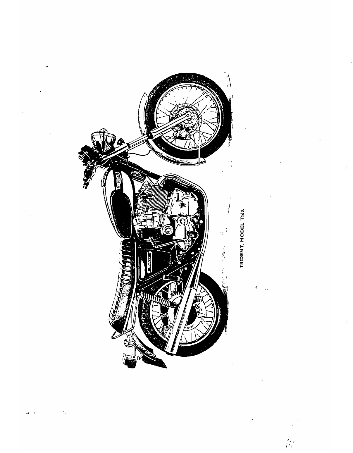
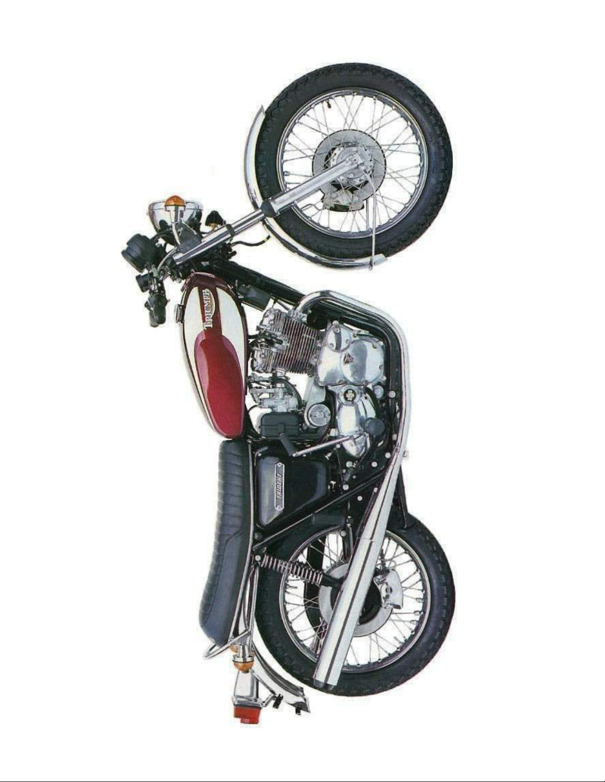
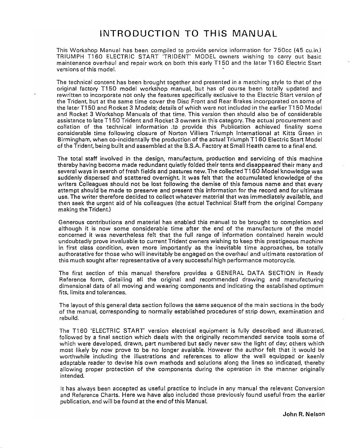
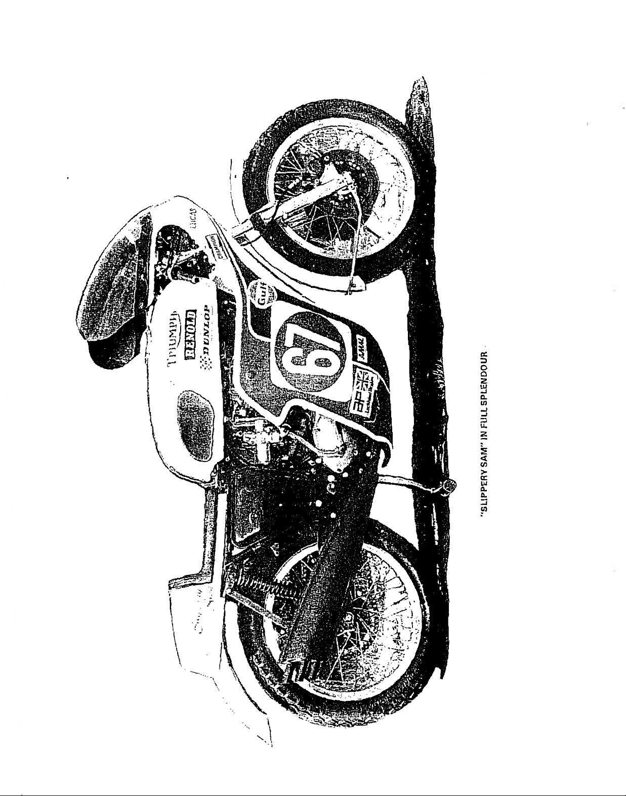
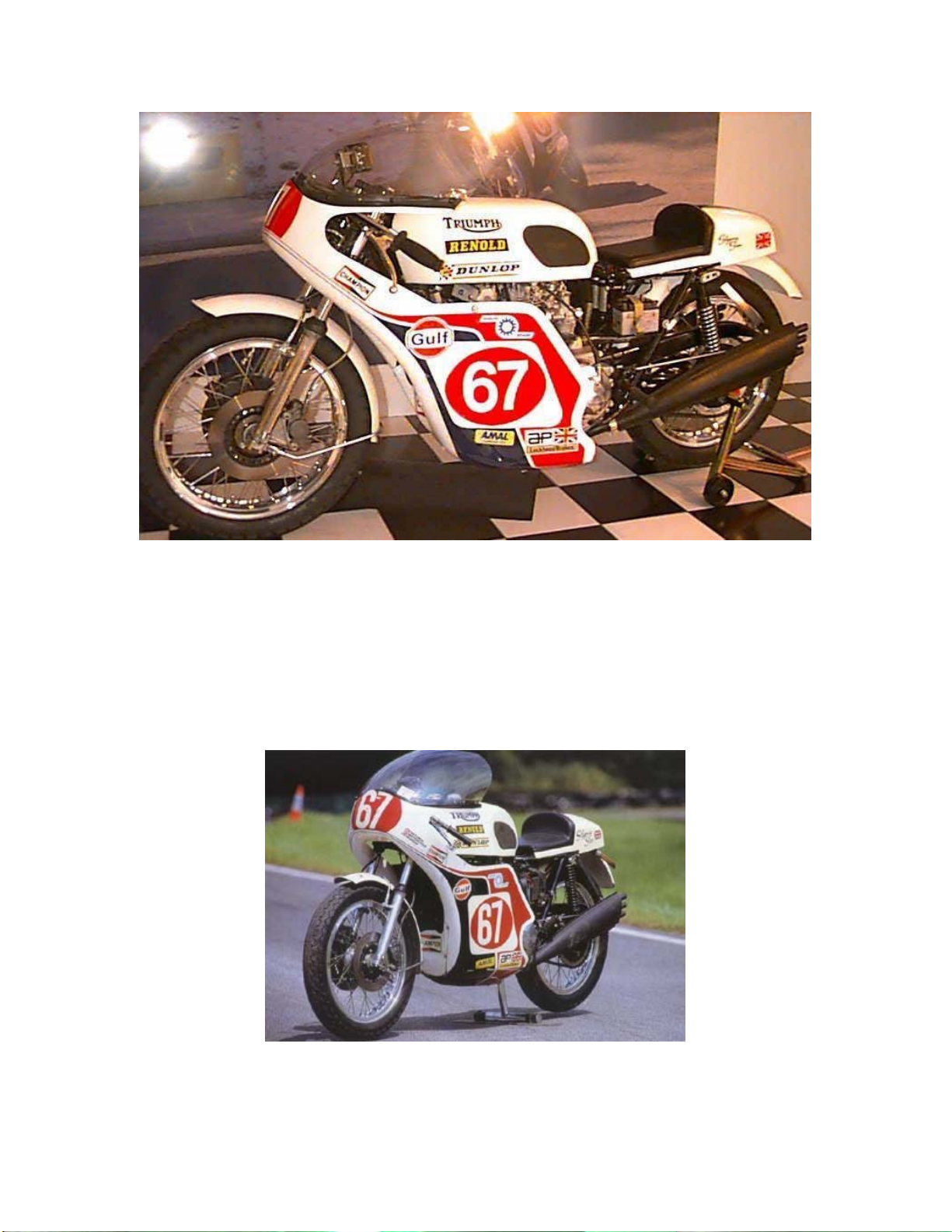
1975 Trident T160
'SLIPPERY
ClassicBike.biz
SAM'
Ourcover design
thevery well known,
Its feats and achievementsasa single individual model to win the Isle
Man Production T.T. Race no less
a place in
spirit and lively response
T150
and
\
the
T160
shows
AnnalsofT.T. history, and is truly representativeofthe sense
model series.
the legendary Triumph Trident model which earned
but
possibly dubious
than
built
into
all
titleof"Slippery Sam".
five years in succession have earned
the
Triumph Trident models in both the
of
it
of
INTRODUCTION
ClassicBike.biz
This
Workshop
TRIUMPH
maintenance overhaul and repair
versions of this model.
T160
Manual
ELECTRIC
has been
START
TO
compiled
work
to provide service
'TRIOENT' MOOEL owners
on both
this
earlyT150
THIS
MANUAL
information
wishing
and
the
laterT160
for
750cc
to
(45
carry
out
Electric Start
cu.in.l
basic
The technical
original factory
rewritten
the Trident.
the later
and Rocket 3
assistance to late
collation
considerable
Birmingham,
of
the Trident, being
The total
thereby having
several ways in search
suddenly dispersed and
writers
attempt
use, The
then seek the
making the Trident.)
Generous
although
concerned
undoubtedly prove invaluabletocurrent
first
in
authoratative
this
much sought
content
to incorporate
butatthe
T150
and
Workshop
of
the
time
when
staff
become
Colleagues
should be
writer
therefore decidedtocollect
urgent
contributions
itisnow
it
was
class condition, even
for
has been
T150
involved in
model
not
same
Rocket3Models;
T150Trident
technical
following
co-incidentally
built
and
made
of
fresh
scattered
should
madetopreserve and present this information
aidofhis colleagues (the actual Technicai
and
some
nevertheless
those
who
after
representativeofa very successful high performance
brought
workshop
only
the
time
cover
Manualsofthat
and
Rocket3owners
information
closureofNorton Villiers
the
assembled
the
design, manufacture, production and
redundant
fields
and pastures new. The collected
overnight.Itwas
not
be
lost
material
considerable
felt
more
will
inevitably
together
manual,
features specifically exclusive to
the Disc Front and Rear Brakes
detailsofwhich
time, This version then should also beofconsiderable
.tp provide this Publication
productionofthe actual Triumph
atthe B.S.A. Factory at Small
quietly
following
has enabled
time
that
the
Trident owners wishingtokeep
importantly
be engagedonthe
and presented in a
but
were
in this category, The
folded
felt
the
demiseofthis
whatever
full
material
this
after
the end
rangeofinformation
as the inevitable
matching
has
of
course
not
includedinthe
Triumph
their
tents
that
the
that
manual tobebrought
of
overhaul and
been
the
Electric
incorporated
actual procurement
achieved
International
T160
Heath
servicingofthis
and
disappeared
T160
accumulated
famous
for
the
was
immediately
Staff
from
the
manufacture
contained
this
time
styletothatofthe
totally
Electric
cametoafinai end.
Model
name
record
the
prestigeous machine
approaches, be
ultimate
motorcycle.
updated and
Start
earlierT150
finality
at
Kitts Green in
their
knowledge
knowledgeofthe
and
and
available, and
original Company
to
completion
of
herein
restoration
version
on some
Model
some
Start
Model
machine
many and
that
every
for
ultimate
the model
would
totally
of
of
and
was
and
of
The
first
section
Reference form, detailing all
dimensional dataofall
fits, limits and tolerances.
The layout
of
the manual, correspondingtonormally
rebuild.
The
followed
which
most
worthwhile
adaptable reader to
allowing proper
intended.
It
has always been
and Reference Charts. Here
publication, and
of
T160
'ELECTRIC
by a final
were developed,
likely by
of
this
moving
this general data
START'
section
drawn,
now
provetobe no
including
willbefoundatthe
the
devise
protection
acceptedasuseful
manual
the
and
section
version
which
part
illustrations
his
own
of
the
we
have
therefore provides a GENERAL
original and recommended
wearing
deals
numbered
longer
methods
components
end
compo'nents and indicating
follows
practicetoinclude in any manual
also included those previously
the samesequence of the
established proceduresofstrip
electrical
with
avaiable.
and references
ofthis
equipment
the
originally recommended service
but
sadly never saw the
However
and solutions along the
during the operation in
Manual.
to
allow the
is fully
the
DATA
drawing
author
found
SECTION in Ready
and
the
established
main
sections
down,
described
lightofday; others
felt
well
equipped
lines
so indicated, thereby
the
manner
the
relevant
useful
manufacturing
optimum
in the body
examination and
and illustrated,
tools
some
which
thatitwould
or
keenly
originally
Conversion
from
the
earlier
JohnR.Nelson
of
be
l:l.
ClassicBike.biz
l:l.
::;
r'
::J
o
z
"
W
...l
l:l.
en
...l
...l
ir
~
~
<t
en
>
0:
W
0:
ClassicBike.biz
Slippery Sam
FOREWORD
ClassicBike.biz
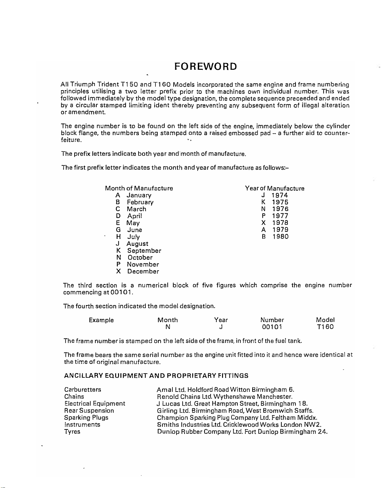
All Triumph
principles utilising a
followed
by a circular stamped
or
amendment.
The engine
block flange.
feiture.
The prefix lettersindicate
The
first
TridentT150
two
immediatelybythe
limiting
numberisto
the
numbers
prefix
letter
indicates
MonthofManufacture
A
January
B February
C
March
D
April
E
May
G
June
H
July
J
August
K
September
N
October
P
November
X
December
andT160
letter
model
ident
be
found
being
both
year
the
Models incorporated the same engine and frame numbering
prefix priortothe machines own individual number. This
type
designation. the complete sequence preceeded and ended
thereby preventing any subsequent
on the
stamped
and
month
left
sideofthe engine. immediately
onto a raised embossed pad - a
'.
monthofmanufacture.
and
yearof
manufactureasfollows:-
Yearof
formofillegal alteration
below
further
Manufacture
1974
J
K
1975
N
1976
P
1977
X
1978
A
1979
8
1980
aid to counter-
the cylinder
was
The
third
section is a
commencing at
The
fourth
Example
The
frame
The
frame
timeoforiginal
the
ANCILLARY
Carburetters
Chains
Electrical Equipment
Rear Suspension
Sparking Plugs
Instruments
Tyres
001
section
numberisstampedonthe
bears
the
EQUIPMENT
numerical
01.
indicated
same
manufacture.
the
serial
AND
block
model
Month
N
numberasthe engine unitfitted intoitand hence were identical at
PROPRIETARY
Amal
Renold Chains Ltd. Wythenshawe Manchester.
J Lucas Ltd. Great Hampton Street. Birmingham 18.
Girling
Champion Sparking Plug Company
Smiths
Dunlop
of
five figures which comprise
designation.
Year
J
left
sideofthe frame. in
FITTINGS
Ltd. Holdford
Ltd. Birmingham
Industries Ltd. Cricklewood Works London
RubberCompany Ltd. Fort Dunlop Birmingham 24.
Road
Witton
Road.
Number
00101
front
of the fuel tank.
8irmingham
West
Bromwich Staffs.
Ltd.
Feltham Middx.
the
6.
engine
NW2.
number
Model
T160

ACKNOWLEDGEMENTS
ClassicBike.biz
The
compilationofthis publication results
former
Service Department, and
WoolridgeofTriumph
of
Due
greatful
Messrs Cork Gully &
with
previously used on Triumph
and
colleagues
'Slippery
to
and produce this Manual, utilising (where appropriate) existing technical
completionofthis project.
Sam', perhaps
the
tortuous pathofownershipofthe
acknowledgement is freely giventoMr.
Jack
Harper and
Motorcycles
Co.
Arthur
with
practical
(Meriden) Ltd., andofcourse Leslie Williams the proud
the
most
famous
andtoTriumph
Trident
publications,
from
generous
Lupton,
help
Tridentofthem
Motorcycles
both
and advice from many friends, including Harry
namesofTriumph,
Dennis
which
and accurate contributions made
previously
all.
Poore, N.V.T., the Receiver N.T.I. Ltd.,
(Meriden) Ltd.
has proved so invaluable in the compilation
DISCLAIMER
for
many years
8.SA,
from
with
the
8.S.A.
owner
N.V.T.M. and 'TRIDENT',
for
permissiontoproceed
matter
and
December
artwork
J.R.N.
1981.
Whilst
maintain
the
development
those
responsibility whatsoever
errors in any
every endeavour has been madebyall
its technical accuracy,itmustbeappreciated
closureofthe
responsible
factory
facility,
for
way
whatsoever.
with
the composition and
those
where
manufacture
consequent
for
any errors,oranydamageordamages arisingorensueing
disbandmentofthe
took
publicationofthis
contributing
that
place and the loss of the associated design and
to this publication to assure and
compilation a
original drawing facilities and records,
Workshop
number
Manual, cannot accept any
of years
from
after
such
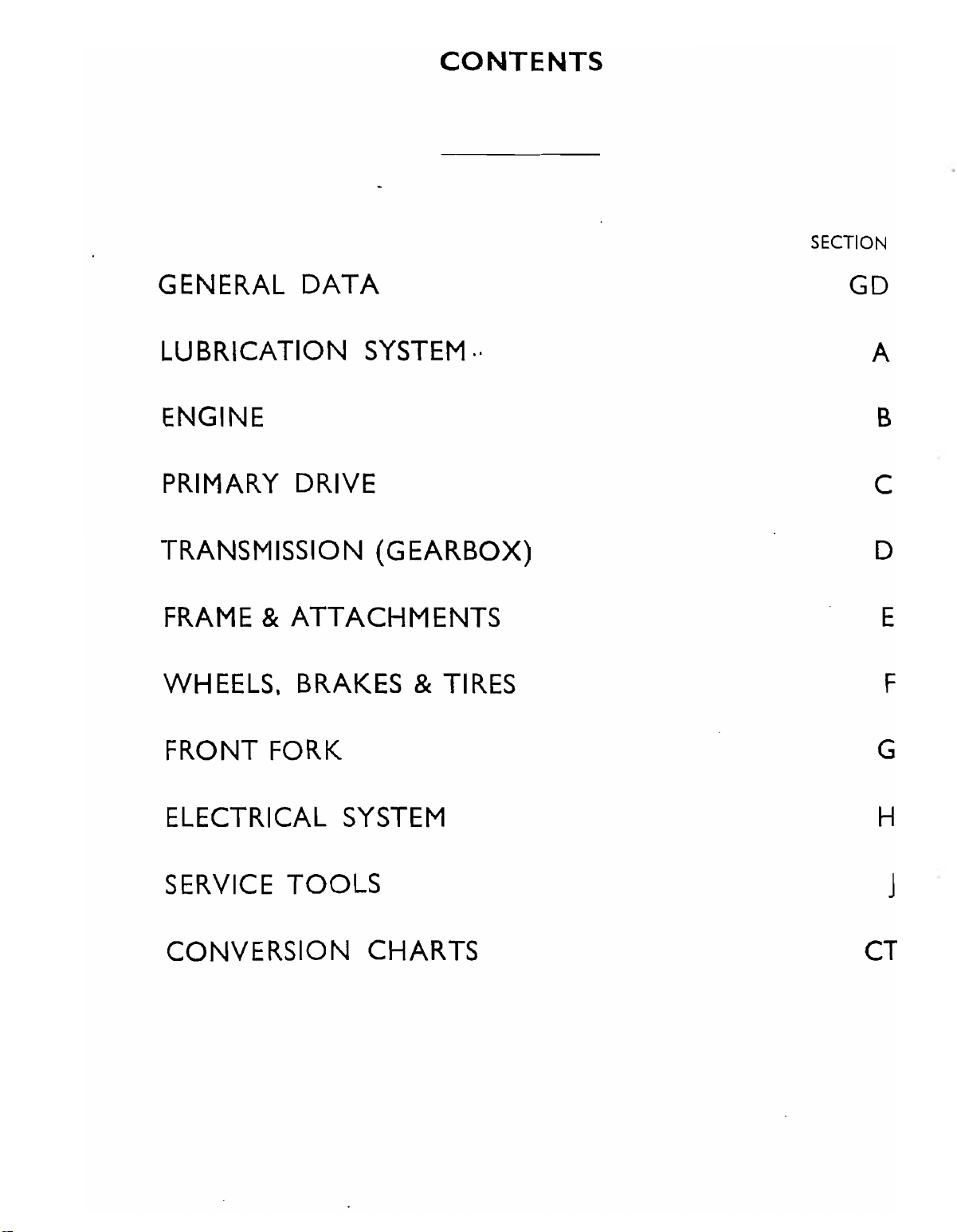
CONTENTS
ClassicBike.biz
See Bookmarks
SECTION
GENERAL
LUBRICATION
DATA
SYSTEM
ENGINE
PRIMARY DRIVE
TRANSMISSION
FRAME &
ATTACHMENTS
(GEARBOX)
WHEELS. BRAKES
..
& TIRES
GO
A
B
C
0
E
F
FRONT FORK G
ELECTRICAL SYSTEM
SERVICE
CONVERSION
TOOLS
CHARTS CT
H
J

ClassicBike.biz
·.
ClassicBike.biz
GENERAL
TRIDENT
MODEL
750
C.c.
(45 cu. ins.)
DATA
TI60
GDl
GD
ClassicBike.biz
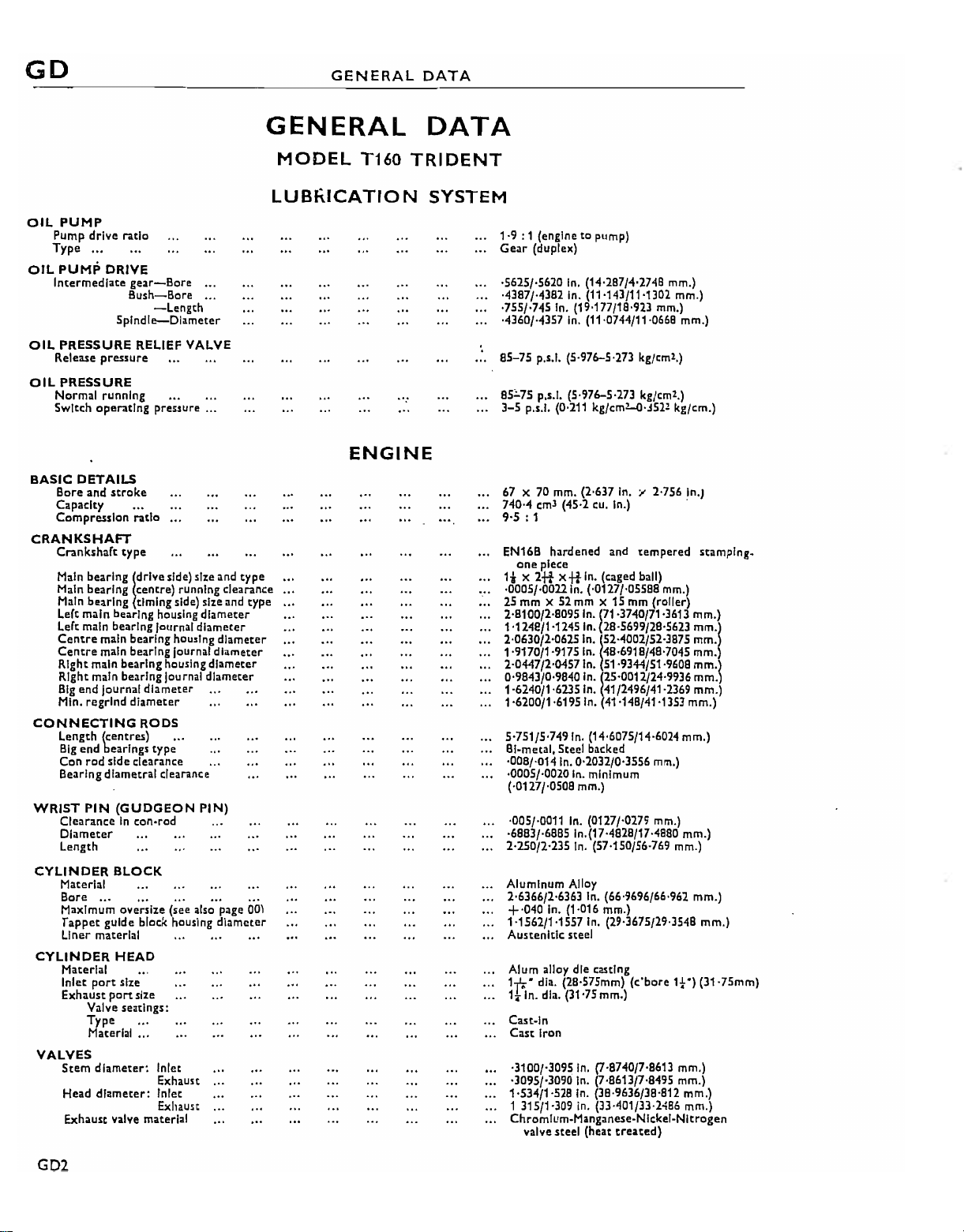
GENERAL
DATA
OiL
PUMP
Pump
drive
Type •..
OIL
PUMP
Intermediate:
ratio
DRIVE
gear-Bore
Bush-Bore
Spindle-Diameter
OiL
PRESSURE
Release pressure
OiL
PRESSURE
Normal running
Switch operating pressure ...
BASIC
DETAILS
Bore and
CapaCity
Compression ratio
CRANKSHAFT
Crankshaft type
Main
bearing
Main
bearing
Main
bearing
Left
main
Left main
Centre
Centre
Right
Right main
Big
end
Min.
regrind
CONNECTING
Length
Big
end
Con
rod
Bearing
WRiST
CYLINDER
CYLINDER
PIN
Clearance
Diameter
Length
Material
Bore...
Maximum
Tappet
Liner
Material
Inlet
Exhaust
Valve
RELIEF VALVE
stroke
!drlVe side) size and
centre)
timing
bearing housing
bearing
main
bearing
main bearing journal
main
bearing
bearing
Journal
diameter
diameter
RODS
(centres)•__
bearings
side
clearance
dlametral
(GUDGEON
In
con~rod
BLOCK
..,
oversize
guide
block housing
materIal
HEAD
port
size
port
size
seatings:
Type
Material
...
VALVES
Stem
diameter~
Head
diameter:
Exhaust
valve material
-Length
funning
side) size and
diameter
Journal
diameter
housIng
housing
Journal
type
clearance
diameter
diameter
diameter
PIN)
(see also page 00)
Inlet
Exhaust
Inlet
Exhaust
type
clearance
type
diameter
diameter
GENERAL
MODEL
LUBKICATION
T160
ENGINE
DATA
TRIDENT
SYSTEM
1-9 : 1 (engine
Geilr (duplex)
·5625/·5620
·4387/·4382 In. (11'143/11'1302 mm.)
·755/·745 In. (19·177/18·923 mm.)
·4360/·4357
85-75
85~75
3-5
p.•.!. (0,211 kg/em2..()·j522 kg/em.)
67 X70mm. (2-637 In. Y 2-756 In.)
740·4
9·5
: 1
EN16B
one
1* X
·0005/·00llln.
25
mm
2·8100/2·8095
1-1248/1·1245
2'0630/2-0625ln.!52.4002/52-3875
1·9170/1-9175In. 48·6918/48-7045
2·0447/2-0457 In. 51·9344/51·9608
0'9843/0·9840 In.!25'0012/2409936 mm.)
1·6240/1·6235In. 41/2496/41·2369 mm.)
1-6200/1-6195In. 41-148/41'1353 mm.)
5·751/5-749
BI~metal.
·008/·014
·0005/·0020 in. minimum
(·0127/·0508 mm.)
'005/·0011
·6883/·6885 In.(17·4828/17·4880 mm.)
2·250/2·235
Aluminum
2-6366/2-6363 In. (66'9696/66-962 mm.)
+·040 In. (1-016 mm.)
1-1562/1-1557
Austenitic
Alum alloy dIe casting
1-p;" dia. (2S·575mm)
1.ln.
Cast-In
Cast
·3100/·3095
·3095/·3090 In. (7·8613/7·8495 mm.)
1·534/1-528
1315/1·309
Chromlum-Manganese-Nlckel-Nitrogen
valve
to
pump)
In.
(14·287/4·2748 mm.)
In.
(11·0744/11-0668 mm.)
p.•.I.(5·976-5'273 kg/em2.)
p.'.!' (5-976-5·273 kg/em2.)
em'
(45-2
cu.
In.) .
hardened
piece
2+t
x+t
X 52 mm X 15 mm (roller)
5teel backed
In.
dla. (31'75 mm.)
iron
steel
and
tempered
In.
(caged ball)
(·0127/·05588 mm.)
In.
(71·3740/71·3613
In.
(28·5699/28·5623
In.
(14-6075/14-6024 mm.)
0·2032/0·3556 mm.)
In.
(0127/·0279 mm.)
In.
(57·150/56·769 mm.)
Alloy
In.
(29·3675/29·3548
steel
(c'
bore
In.
(7·8740/7·8613 mm.)
In.
(38·9636/38·812 mm.)
in.
(lJ·401/33·2486
(heat
treated)
stamplng~
mm.)
mm'l
mm.
mm.
mm.)
mm.)
1t·)
(31·75mm)
mm.)
GD2
GENERAL
ClassicBike.biz
.
DATA
GD
.",11.
~_
'.
I
~'z.,.
I j
...-11.;;:1
~,P
~-
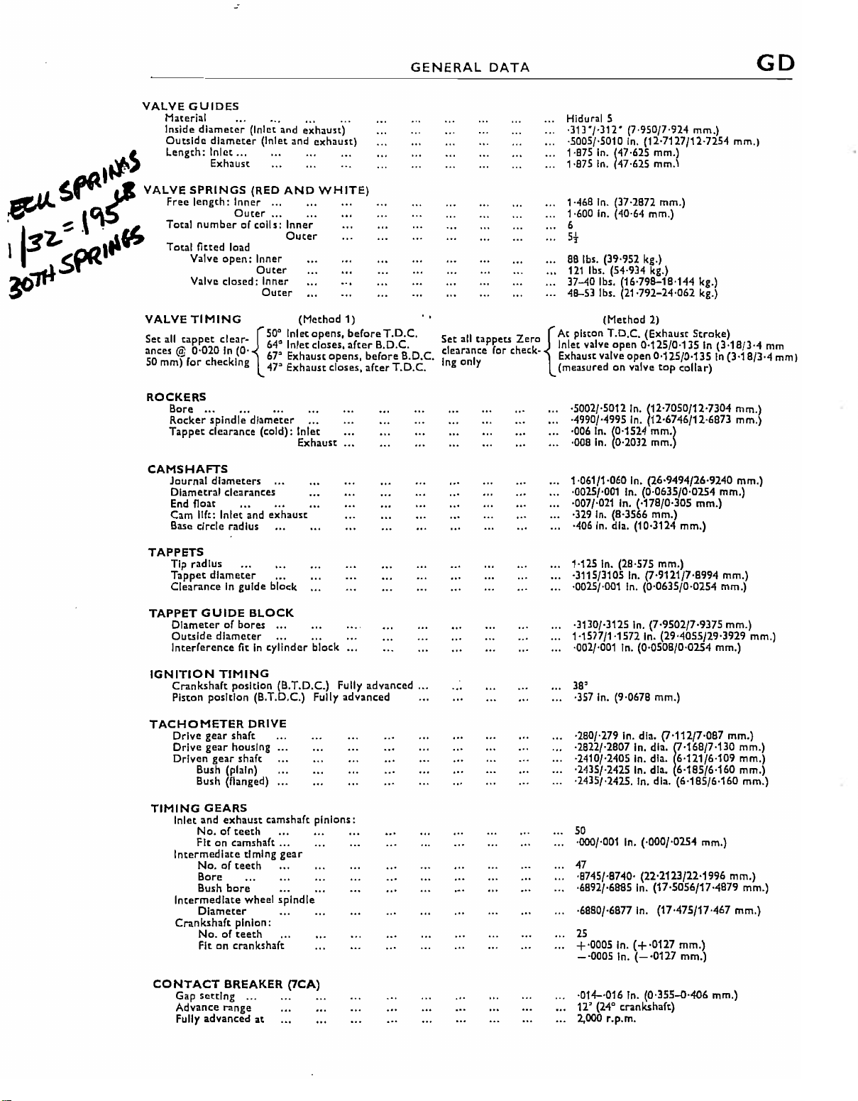
VALVE
•
"IA
~
s".~
I""
~.\.
pair
t!1
.1
~
VALVE
VALVE
Set
:loees @ 0-020In(0'
50
GUIDES
Material
Inside
diameter
Outside
Length:
Free
Total
Total
all
mmf
ROCKERS
CAMSHAFTS
diameter
Inlet
Exhaust
SPRINGS
length:
numberOou/~~il';;
fitted
Valve
Valve closed: Inner
TIMING
tappet
for checkln
Bore
...
Rocker
spindle
Tappet
clearance (cold): Inlet
Journal
diameters
Dlametral clearances
End
float
Cam
11ft:
Base
circle
(Inlet and
(Inlet and exhaust)
'"
(RED
Inner..,
load
open:
Inner
Outer
Outer
c1ear_{50:
g
diameter
Inlet
and
radius
_.....
exhaust)
...
_..
.
..
AND
WHITE)
Inn~;'
Queer
(Mechod
[nletcpens,
640Inlet closes.
67
Exhaust
47"
Exhaust closes,
Exhaust •..
exhaust
...
1)
beforeT.D.C.
after
opens,
B.D.C.
before
after
B.D.C.
T.O.C.
Hldural 5
·313"/,312'
,5005/,5010
1·875 In. 147'625 mm.)
1·875
10468 In. (37·2872 mm.)
1,600 In, (40,64 mm,)
6
5,
88 Ibs, (39'952 kg,)
121
37-40 Ibs,
48-53 Ibs,
, ,
5t all
til
ts Z
cfearancepr~r
Ing only Exhaust valve
{At
chee:k~
Jnlct valve
(measuredonvalve
·5002/,5012 In,
,4990/,4995 In. (12·6746/12-6873
·006 In. (0,1524 mm.)
·008
1'061/10060 In, (26,9494/26,9240
,0025/,001 In, (0·063S/0,0254 mm.)
,007/,021 In. (,178/0,305
,329 In, (8,3566
,406
In.
47·625
Ibs, (54-934 kg,)
(16'798-18,144
(21·792-24,062
(Mechod 2)
piston
T.O.C.
open
In.
(0·2032 mm.)
In,
dla, (10·3124
(7,950/7,924
In,
(12,7127/12,7254
(Exhaust
0·125/0·135In(3·18/3'4
open
(12,7050/12,7304
mm,)
mm.\
Stroke)
0·125/0·135
top
collar)
mm.)
mm,)
mm.)
kg,)
kg.)
In
mm,)
(3·18/3·4
mm.)
mm,)
mm,)
mm
mml
TAPPETS
Tip
radius
Tappet
diameter
ClearanceInguide
TAPPET
IGNITION
TACHOMETER
TIMING
GUIDE
Diameterofbores
Outside
Interference
Crankshaft
Piston
Drive
Drive
Driven
diameter
TIMING
position
gear
gear
gear
Bush (plain)
Bush (flanged)
GEARS
Inlet
and
exhaust
No.ofteeth
Fitoncamshaft
Intermediate
No.ofteeth
Bore
Bush
IntermedIate
Diameter
Crankshaft
No.ofteeth
Fitoncrankshaft
position
shaft
housIng
bore
..•
...
block
BLOCK
...
•.. .
fitIncylinder
(B.T.D.C.) Fully
(B.T.D.C.) Fully
DRIVE
shaft
camshaft
.
timing
wheel
pinion:
.
gear
spindle
...
..
block
pinions:
...
advanced
advanced
...
1-125 In. (28'575 mm,)
·3115/3105
,0025/,001 In, (0,0635/0·02S4 mm,)
·3130/,3125 In, (7,9502/7,9375
1-1517/1-1572 In. (29,4055/29,3929 mm,)
,002/,001 In, (0,0508/0,0254 mm,)
38'
,357 In, (9'0678 mm,)
'280/'2791n,
,2822/,2807 In, dla,
·2410/·2405 In, dla,
,2435/·2425 In, dla.
,2435/,2425, In. dla,
50
,000/·001 In, (,000/,0254
47
,8745/·8740·
,6892/,6885 In.
,6880/·6877 In, (17,475/17,467
25
+,0005 In.
- ·0005 In,(-·0117
In,
(7,9121/7,8994
dla.
(7,112/7,087
~'168/7'130
6,121/6·109
6·185/6·160
(6,185/6,160
(22,2123/22'1996
(17'5056/17'4879
(+
,0127
mm,)
mm.)
mm.)
mm,)
mm.)
mm.)
mm.)
mm,)
mm,)
mm,)
mm,)
mm,)
mm.)
CONTACT
Gap
Advance
Fully
BREAKER
setting
range
advanced
(7CA)
...
at
,01'1-,016 In. (0,355..
12'
(24" crankshaf<)
2,000
r.p,m,
1H06
mm,)
GD3
GO
ClassicBike.biz
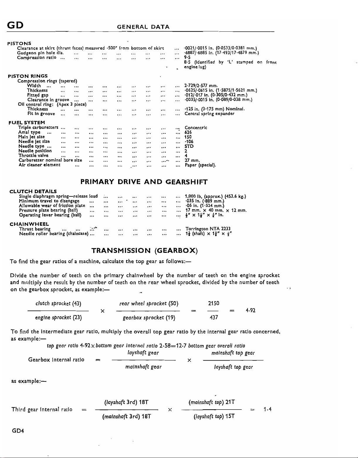
PISTONS
Clearanceatskirt
Gudgeon
Compression ratio ...
PISTON
Compression
011
FUEL
Triple
Amal
Main
Need e Jet size
Needle
Needle position
Throttle
Carburetter
Air cleaner
CLUTCH
Single diaphragm
Minimum
Allowable
Pressure
Operating
CHAINWHEEL
Thrust
Needle
pin hole dla.
RINGS
Width
Thickness
Fltt~d
Clearanceingroove
control
Thickness
In
Fit
SYSTEM
carburetters
type
let
size
type
valve ..•
DETAILS
bearing ... '"
roller
(thrust
faces)
measured
rings
(tapered)
gilp
groove
••
,
ring: (Apex 3 piece)
.•.
•.. •..
•..
nominal bore size
element
PRIMARY DRIVE
spring-release
traveltodisengage •..
wearoffriction plate
plate bearing (ball)
lever bearing (ball)
bearing (chalnca.se) ...
load
;,.;:
·500"
from
bottomofskirt
...
AND
..
·0021/·0015 in. (0·05J3/0·0381
·6887/·6885 In. (17'493/17'4879 mm.)
9-5
a·s
(Identified
engine
lug)
2-729/2-577
·0625/·0615 In. (1·5875/1·5621 mm.)
·012/·017 In. (0.305/0·432
·0035/·0015 In. (0'089/0·038
·115
In.
(3-175
Central spring expander
ConcentrIc
626
150
·106
STD
2
~,
4
27
Paper
rnm
.
(special).
GEARSHIFT
1,000 Ib,
'035
In. (·889 mm.)
·06 In. (1,524
17 mm. X 40
!"
X
11-"
Torrington NTA
1t (shaft) X
by
mm.
mm)
(approx.)
mm.)
mm.
Xt"In.
It''
'L' stamped
Nominal.
(453.6 kg.)
X 12 mm.
2233
X
t"
mm.)
mm.)
mm.)
on
front
To
find
the
Divide
the
and multiply
on
the
gearbox sprocket,asexample:-
clutch
engine sprocket
To
find
the
as
example:-
Gearbox
as
example:-
Third
gear Internal ratio
TRANSMISSiON
gear ratios of a machine, calculate
number
the
of teeth on
resultbythe
sprocket
(43)
the
primary chainwheel by
numberofteethonthe
x
(23)
Intermediate gear ratio, multiply
top
gear
ratio 4·92X
Internal ratio
bottom
gear
=
(Iayshoft
(malnshaft 3rd) 18T
the
top
rear
wheel
gearbox
the
sprocket
overall
Internal
loyshoft gear
malnshaft gear
3rd)
18T
(GEARBOX)
gearasfollows:-
the
number of teeth on
rear
wheel sprocket, dividedbythe
sprocket
ratio
(19)
top
gear
2·58=12·7
(50)
ratiobythe
bottom geor
x
(malnshaft
x
(/oyshoft
the
engine
sprocket
numberofteeth
2150
4·92
437
Internal gear ratio concerned,
overoll
ratio
mOlnshoft
loyshaft
tOp)
21T
top
top
geor
geor
1·4
top)
15T
.,
GD4
GENERAL
ClassicBike.biz
DATA
GO
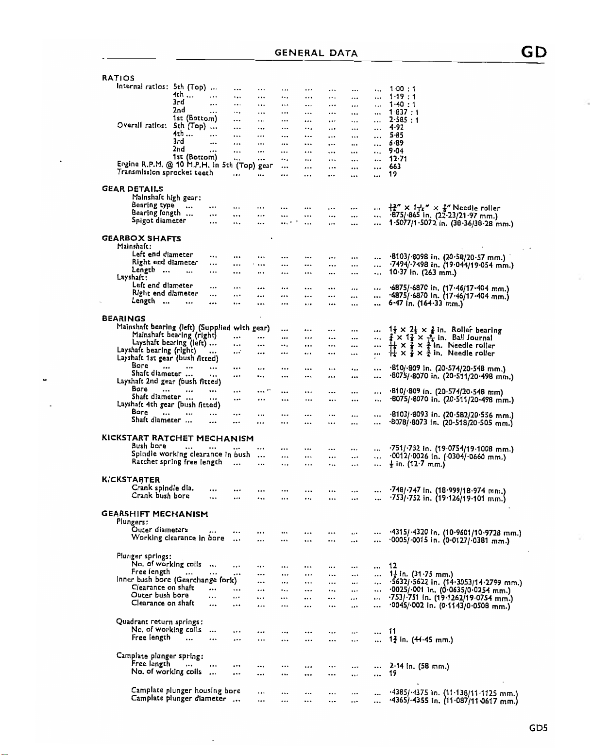
RATIOS
Internal ratios: 5th (Top)
Overall ratios: 5th (Top)
Engln.
R.P.M.
Transmission
GEAR
DETAILS
Malnshaft high
Bearing type
Bearing length
Spigot diameter
GEARBOX
Malnshaft:
Left end diameter
Right end
length
Layshaft:
Left end diameter
Right end diameter
Length~..
BEARINGS
Malnshaft bearing (left) (Supplied
Malnshaft bearing
Laysnaft
Layshaft bearing (right)
layshaft
Bore ...
Shaft diameter
Layshaft 2nd gear (bush fitted)
Bore
Shaft diameter
Layshaft
Bore ..•
Shaft diameter
4th
.,.
3rd
2nd
1st
(Bottom)
4th...
3rd
2nd
1st (Bottom)
@10
M.P.H.
sprocket
gear:
...
SHAFTS
diameter
,.,
hearing (Iert) .
1st
gear (bush fitted)
,..
4th
...
gear (bush
...
teeth
(right)
fitted)
".
".
...
...
In
5th
.,.
...
.._
(Top)
with
gear)
.•, .•.
..,
goa'
1·00 : 1
1019:
1
1040:
1
1·837 : 1
B85
: 1
4·92
5-85
6·89
9·04
12-71
663
19
ft"
X
1ft"
;<
i"
Needle
Ball
roller
mm'j
Journal
roller
roller
·875/·8651n. (22·23/21·97 mm.)
1·50n/l·5072
·8103/·8098 In. 120.58/20'57 mm.) -
·7494/·7498 In. 19·044/19·054 mm.}
10·37 In. (263 mm.)
·6875/·6870 In. 117'46/17'404
'6875/·6870 In. 17·46/17·404 mm.
6·47 In. (164-33 mm.)
1!
X
t x
11
*x
*X
·810/·809 In. (20·574/20·548 mm.)
·8075/·8070 In. (20'511/20'498 mm.)
.810/·809 In. (20·574/20·548 mm)
'8075/'8070 In. (20·511/20'498 mm.)
-8103/'8093 In. (20·582/20·556 mm.)
·8078/·8073 In. (20'518/20'505 mm.)
In.
(38·36/38·28 mm.)
2!
x i in. Roller bearing
x
-r..
In.
txt
In.
in.
Needle
Needle
txt
KICKSTART
KICKSTAIjTER
GEARSHIFT
Bush
bore
Spindle working clearanceInbush
Ratchet spring free
Crank
Crank bush
Plungers:
Outer
Working
Plutlger springs: .
No. ofworking calls
Free length
Inner bush
Clearanceenshaft
Outer
Clearanceenshaft
Quadrant
No. of werking
Free length
Camplate plunger
Free length
Ne.
of werking calls
Camplate plunger housing
Camplate
RATCHET
spindle dla.
bore
MECHANISM
diameters
clearanceinbore
bore
(Gearchange fork)
bush
bere
return
springs:
c01ls
spring:
plunger'diameter
MECHANISM
length
...
...
...
bore
...
'751/·752 In. (19·0754/19·1008 mm.)
-0012/'0026 in. (·0304/-0660 mm.)
fin.
(12-7 mm.)
·748/·747 In. (18·999/18-974
·753/·752 In. (19·126/19·101 mm.
'4315/-4320 In. (10·9601/10·9728 mm.)
'0005/'0015 In. (0-0127/·0381 mm.)
12
1*
In.
(31,75 mm.)
'5632/·5622 In. (14·3053/14·2799 mm.)
·0025/-001 In. (0·0635/0-0254 mm.)
·753/·751 In. (19·1262/19-0754 mm.)
'0045/·002 In. (0'1143/0'0508 mm.)
11
It
In.
(44·45 mm.)
2·14 In. (58 mm.)
19
·4385/·4375 In. 1110138/1101125
·4365/·4355 In. 11-087/11·0617 mm.
mm'j
mm'j
GD5

GO
ClassicBike.biz
GENERAL
DATi,
GEARSHIFT
Cross-shaft
Needle
Link
pin
Link Din diam.
STARTER
Solenoid
Intermediate
Adapter
Intermediate
Intermediate
HEAD
SWINGING
RACES
Taper
roller (top and bottom)
Bush
type
Bush
bore
Bobbin
Distance
REAR
SUSPENSION
Type
.. ,
Centres
Bush
bore
Length of free spring
Spring
CROSS·SHAFT
diamC!tcr
railer
bC<lring
bOie
rlOTOR
and
plate bush
diameter
between
(extended unit)
rate
bearing
shaft
shaft bush
shaft
FORK
.•••
...
MECHANISI"'!
diameter
housing bush
bore
diameter
fork ends
bore
...
bore
FRAME
AND
ATTACHMENT
6250/·6245 in. (15'875/15-862] mm.)
'!"
;.:
+ttl
;.:
·378/·376 In. (=}-601/9·550 mm.)
·3751/·3749 (9·527519·5225 mm.)
1·0018/1·0013
1'0003/·9998In(25'407/25·395 mm.)
·7530/·7518
'4387/'4382
'4372/·4367
til'·
In.
(25'446/25'433 mm.)
In.
(19'126/19'096 mm.)
In.
(11'143/11-130 mm.)
In.
(11·105/11·092 mm.)
DETAILS
Tlmken LM11949L/LMl1910fLM11900E.
Pre-sized
1-4460/1-4470
1-4445/1-4450
7·81 In. (198,4 mm.)
Swinging fork controlled
coil sprlng/hydraullc
n·875
·382/·377
8·810
110Ib,./ln.
steel-backed-phosphor
In.
(36.7284/36·7538 mm.)
In.
(36·6903/36·703 mm.)
(327 mm.)atmid position
In.
In.
(m·8
damper
(9-7028/9-5758 mm.)
mm.)
bronze
by
units
combined
WHEELS
Rim size:
Spoke details:
WHEEL
Front
Front
Rear sleeve
REAR
WHEEL
Gearbox
Rear wheel
Chain details:
Width
Speedometer
Speedometer
BRAKES
Operation
Type
Diameter:
jl'
Brake pad (front)
Brake pad (rear)
WHEELS,
Front
Rear
BEARINGS
and
rear,
spindle diameter (at bearing Jour,nats).
sprocket
No.
of
links: Solo
Pitch
...
Front
Rear
... ..,
Front
Outer
Inner (L.H. and R.H.)
Rear: tnner (L.H. and R.H.)
Ouw
Outer (R.H.)
dImensions and type
diameter
DRIVE
sprocket
(at bearing Journals)
...
-teeth
...
... ...
drive gearbox ratio
cable length _." ..,
.. , ..,
(L.H. and R.H.)
(L.H.)
..,
...
BRAKES
'.::+
AND
TIRES
WM2·19
WM3·19
20
off 10 SWG 7·87
head .
20
off 10 SWG 7·84 in. (mean length)
20
off 10
10 off 10 SWG 8·16
10 off 10 SWG
25
·9841/·9836 (24-9961/24-98:! mm.)
See 'Transmission'.
50
110
tin.
i
1·25 : 1 .
70·5
SWG
head
X 52 X 15
·7873/·7868 (19·9974 (19-9847 mm.)
In.
In.
(1791
HydraulIc
Disc
101n.
254
in.
254
mm.
mm.
10
A.P.4741-537
A.P.4741-570
In.
(overall length)
7·84 in. (mean length) 96"'head
tn.
(overall
8in.
(overall length)
mm.-Ball
mm.)
Journals
96;
length)
80;
80'
head
75;l
head
TIRES
Size:
Front
Rear
Tire
pressure:
GD6
Front
Rear
4·10 X 19 in.
4·10
;.:19In.
26Ib./'q.
28
In.
lb./,q. In. (1,97 kg./sq. em.)
(1-828 kg./'q. em.)
GENERAL
ClassicBike.biz
DATA
GD
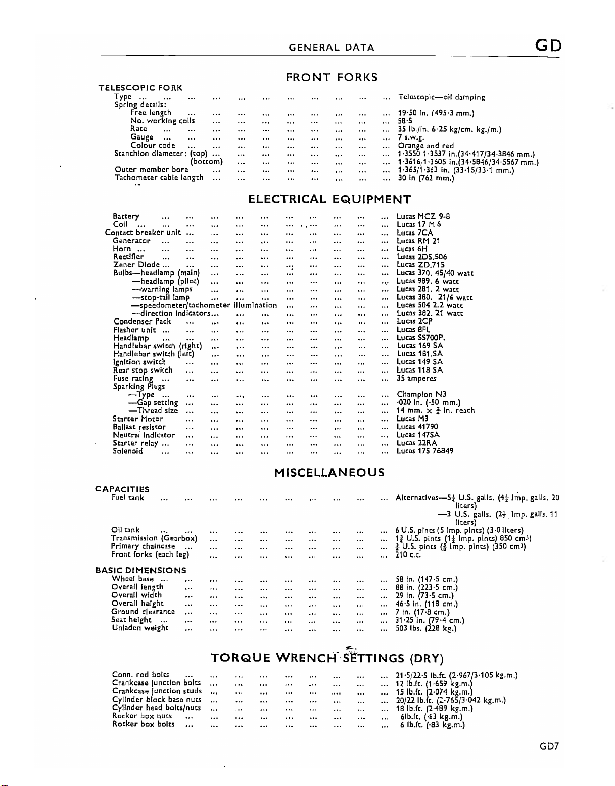
TELESCOPIC
Typo ...
Spring
Stanchion
Outer
Tachometer cable length
FORK
details:
Free
length
No. working colis
Rate
Gauge
Colour
code
diameter:
member
Battery
Coil
Contact
breaker
Generator
Horn
...
Rectifier
Zener
Diode ...
Bulbs-headlamp
-head
lamp (pilot)
-'Narnlng
-stop-tall
-speedometer/tachometer
-direction
Condenser Pack
Flasher
unit
Headlamp ,., ..•
Handlebar
Handlebar switch (leit)
Ignition switch
Rear
Fuse
Sparking
Starter
Ballast
Neutral
Starter
Solenoid
switch
stop
switch
ratlng...
Plugs
-Typo
-Gap
-Thread
Motor
resistor
Indicator
relay
setting
bore
unit
(main)
lamps
lamp
indicators.••
••.
(right)
...
size
...
(top)
(bottom)
ELECTRICAL
ill
urn
1nation
FRONT
"
...
FORKS
EQUIPMENT
....
Telescopic-oil
19·50
In.
56·5
35 Ib./in. 6·25 kg/em. kg./m.)
7 s.w.g.
Orange
1·35501·3537
1-3616,1-3605 In.(34·5B46/34·5567 mm.)
1-365j1-363 In. (33·15/33·1 mm.)
In
(762 mm.)
30
Lucas MCZ 9-8
Lucas 17 M 6
7CA
Lucas
LucasRM21
Lucas 6H
lucas
2D5.506
Lucas
ZD.715
Lucas 370.
Lucas 989. 6
Lucas 281. 2
Lucas 380.
Lucas 504 2.2
lucas
382.21watt
Lucas 2CP
BFL
Lucas
Lucas SS700P.
Lucas 169 SA
Lucas 161.5A
Lucas 149 SA
Lucas 118 SA
3S
amperes
Champion N3
·020 In. (,50
14 mm. X i In.
Lucas
M3
Lucas 41790
Lucas 147SA
Lucas 22RA
Lucas 175 76849
damping
(495·3 mm.)
and
red
In.(34·417/34·3B46 mm.)
45/40
watt
watt
watt
21/6
watt
watt
mm.)
reach
CAPACITIES
Fuel
tank
Oil
tank
Transmission
Primary
Front
(orks
BASiC
DIMENSIONS
Wheel
base
Overall
Overall
Overall
Grou ndcIearance
Seat
height
Unladen
Conn.
rod
Crankcase
Crankcase
Cylinder
Cylinder
Rocker
Rocker
(Gearbox)
chalncase
(each leg)
...
length
width
height
...
weight
bolts
Junction bolts
Junction
block
base
head
bolts/nuts
box
nuts
box
bolts
studs
nuts
TORQUE
M
ISCELLAN
EOUS
:s:.,.
WRENCI-:(SETTINGS
Alternatives-5!
U.S.
pints (5 Imp. pints) (3·0 lIeers)
6
1:
U.S. pints
•
U.S.
pints(tImp. pines) (350 em
210
C.c.
5B
In.
(147·5 em.)
BB
In.
(223·5 em.)
29
In.
(73·5
46·5
In.
(11
7 In.
(17-8
31'25 in. (79,4 em.)
503 Ib,.
(22B
-3
(1!-
em.)
B em.)
em.)
k8.)
U.S. galls.
liters)
U.S. galls.
liters)
Imp.
(DRY)
21-5/22·5
12 Ib.ft. (1-659 kg.m.)
15
20/22 Ib.fe.
18 Ib.fe. (2·4B9 kg.m.)
Ib.n.
(2-967/3·105
Ib.ft. (2·074 kg.m.)
(:·765/3-042
(·B3
(·B3
kg.m.)
kg.m.)
6Ib.ft.
6 Ib.fe.
pints)
kg.m.)
(4t
Irop.
(2t
.Imp.
850 em.')
kg.m.l
galls.
20
galls.
11
J
)
GD7
GD
ClassicBike.biz
GENERAL
DATA
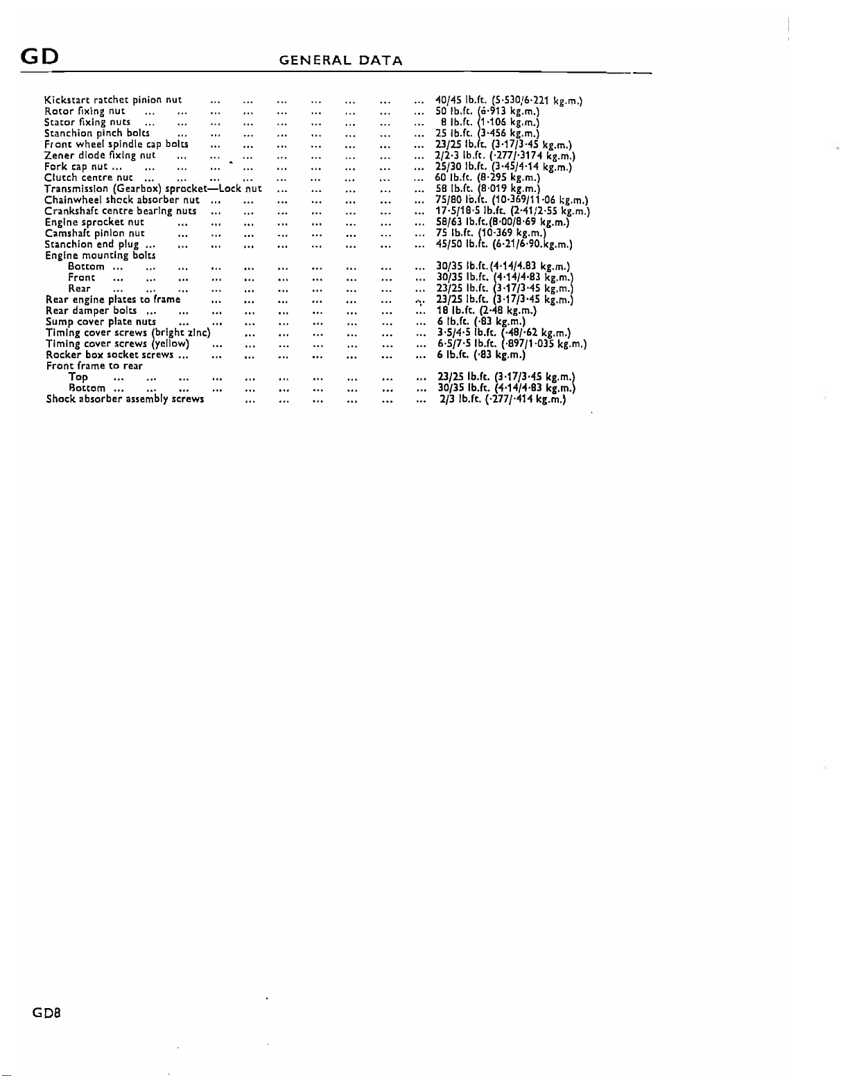
Kickstart
Rotor
Stator
Stanchion
Front wheel spindle
Zener
Fork cap
Clutch
Transmission (Gearbox)
Chainwheel sheck absorber nut
Crankshaft centre bearing nuts
Engine
Camshaft pinion
Stanchion end plug..,
Engine mounting bolts
Rear engine plates to frame
Rear
Sump
Timing cover screws lbrlght zinc)
Timing cover screws yellow)
Rocker box socket screws
Front
Shock
ratchet
fixing
fixing nuts
diode fixing nut
nut
centre
sprocket
Bottom
Front
R.ear
damper bolts ..,
cover
frametorellr
Top
Bottom
absorber
pinion
nut
pinch bolts
...
nut
nut
nut
...
plate nuts
...
assembly
nut
cap
bolts
...
".
sprocket-Lock
....
..
......
.,_
.., ...
screws
...
nut
40/45 Ib.ft.
50
8 Ib.ft. 1·106 kg.m.l
25Ib.ft. 3·456 kg.m.l
23/25
2/203
25/30 Ib.ft. (3·45/4·14 kg.m.l
60
5B
75/BO
17·5/1B·5
5B/63
75
(5-53016,221
Ib.ft'la'913 kg.m.l
IbA
(3·17/3-45 kg.m.l
Ib.ft. ('277/·3174 kg.m.)
Ib.ft. (8,295 kg.m.l
'b.ft'IB'019 kg.m·l
10.
t. (10·369/11·06 kg.m.l
Ib.f~
Ib.ft.(B·00/B·69 kg.m.l
Ib.ft. (10·369 kg.m.)
(2·41/2-55 kg.m.)
kg.m.l
45/50 Ib.lt. (6·21/6·90.kg.m.l
30/35 Ib.ft. (4·14/4.B3 kg.m.l
30/35
23/25Ib.ft. 3·17/3-45 kg.m.
.,. 23/25 Ib.ft. 3·17/3-45 kg.m.
1B
Ib.ft. (2·48 kg.m.)
6 Ib.ft.
...
3·5/405 Ib.ft. (·4B/·62 kg.m.l
6·5/7-5 Ib.ft. (·B97/1-035 kg.m.l
6 Ib.ft.
23/25 Ib.ft. (3·17/3·45 kg.m'l
30/35 Ib.ft. (4·14/4-83 kg.m.
'b.ft·1
(·83
('B3
4'14
kg.m.)
kg.m.)
/4-B3
kg.m'l
2/3 Ib.ft. ('277/·414 kg.m.'
GDB

SECTION
ClassicBike.biz
A
ROUTINE
TABLE OF
ENGINE
CHANGING
OIL
THE
REMOVING
REMOVING
REMOVING
ANTI-DRAIN
LUBRICATION
PRESSURE
OIL
PRESSURE
LUBRICATION
RECOMMENDED
SYSTEM
THE
ENGINE
...
RELEASE
AND
REPLACING
AND
REPLACING
AND
REPLACING
VALVE
LUBRICATION
LUBRICANTS
OIL
AND
CLEANING
VALVE
THE
OIL
THE
OIL
THE
ROCKER OIL
...
...
...
.'
PUMP
COOLER
THE OIL
FEED
SYSTEM
FILTERS
PIPE
Section
...
A1
... A2
...
A3
...
A4
...AS
'"
A6
...
A7
...
A8
...
A9
...
A10
CONTACT
TRANSMISSION
PRIMARY
REAR
GREASING
WHEEL
TELESCOPIC FORK
LUBRICATION
LUBRICATING
SPEEDOMETER CABLE
REAR BRAKE SPINDLE
CHANGING
BREAKER
CHAINCASE
CHAIN
THE
BEARING
THE
(GEARBOX)
LUBRICATION
STEERING
LUBRICATION
NIPPLES
THE
OILINTHE
LUBRICATION
LUBRICATION
LUBRICATION
AND
HEAD
LUBRICATION
CONTROL
LUBRICATION
LUBRICATION
CABLES
BRAKING
MAINTENANCE
RACES
SYSTEMS
...
...
...
...
...
...
...
...
...
...
...
...
A11
An
A13
A14
A1S
A16
A17
A18
A19
A20
A21
A22
A1
A
ClassicBike.biz
LUBRICATION
SYSTEM
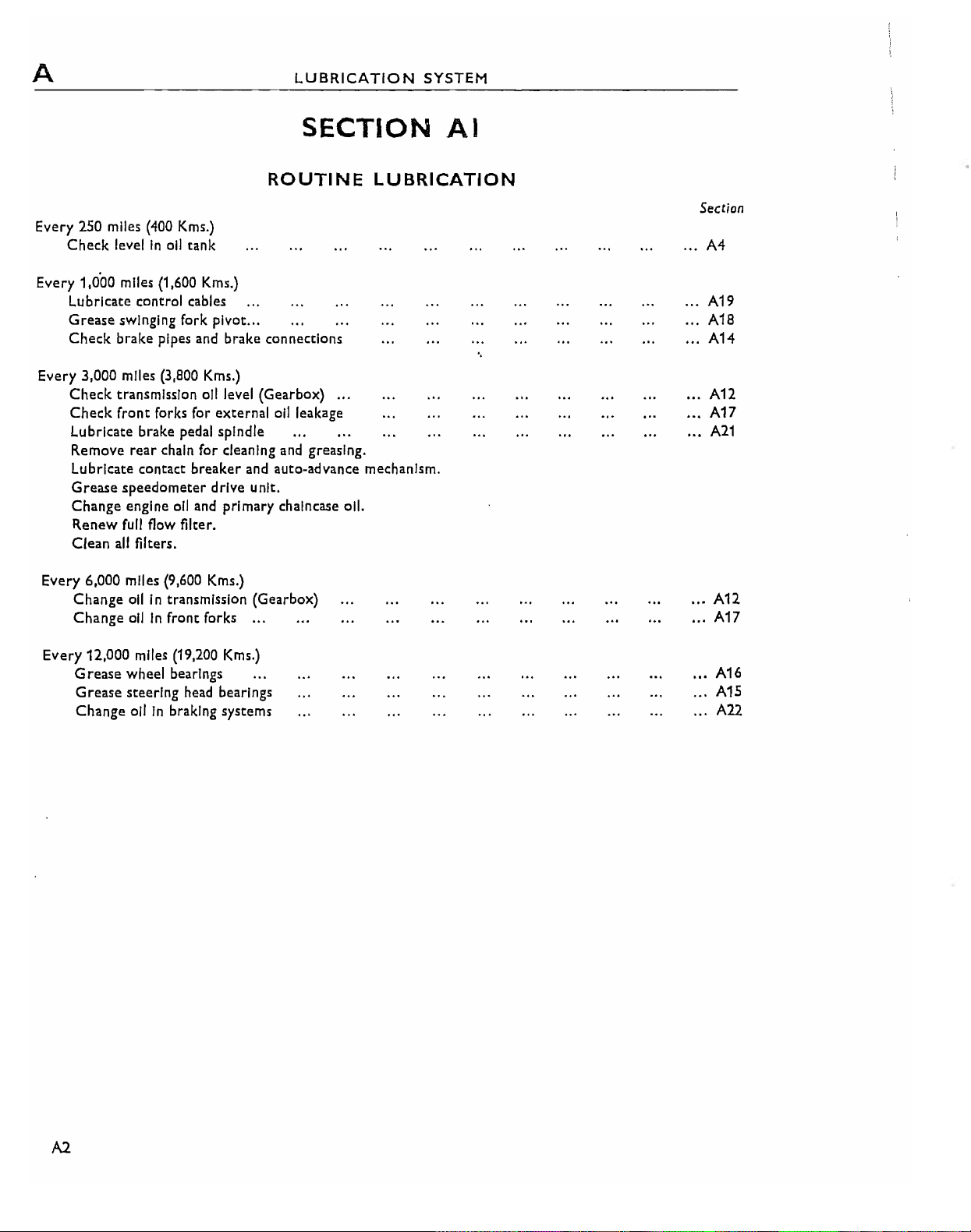
Every 250 miles
Check
Every 1,0'00 miles (1,600 Kms.)
Lubricate control cables
Grease
Check
Every 3,000 miles (3,800 Kms.)
Check
Check
Lubricate brake pedal spindle
Remove
Lubricate contact
Grease
Change
Renew
Ciean
Every 6,000 miles (9,600 Kms.)
Change
Change
(400
Kms.)
levelinoil
swinging fork pivot ...
brake pipes and brake connections
transmission oil level (Gearbox)
front
rear
speedometer
engine oil and primary chalncase oil.
full
all
filters.
oilIntransmission (Gearbox)
oilinfront forks
tank
forks for external
chain for cleaning and greasing.
breaker
drive unit.
flow filter.
SECTION
ROUTINE
oil
leakage
and auto-advance mechanism.
...
LUBRICATION
AI
Sec
...
A4
...
A19
A18
... A14
...
An
..•
A17
'"
A21
..,An
.., A17
lion
Every
12,000 miles (19,200 Kms.)
Grease
Grease
Change
wheel bearings
steering head bearings
oilinbraking systems
.., A16
A15
..,
All
A2
LUBRICATION
ClassicBike.biz
SYSTEM A
Ref.
10
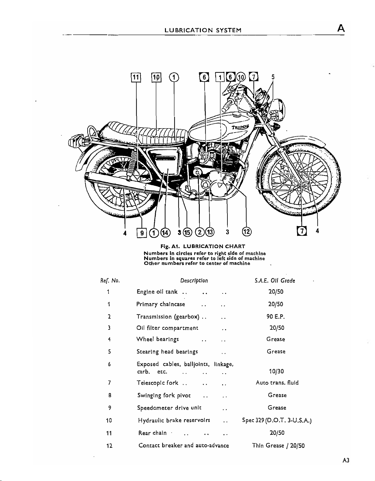
Fig.
AI.
LUBRICATION
NumbersIncircles refertoright
NumbersInsquares refer to left
Other
numbers
No.
1
1
1
3
4
5
6
7
B
9
Engine oil
tank
Primary chalncase 10/50
Transmission (gearbox)
all
filter
compartment
Wheel
bearings
Stearing head bearings
Exposed cables, baliloints, linkage,
carbo
Telescopic
SWinging
Speedometer
Hydraulic
etc.
fork
fork
brake
refertocenterofmachine
Description
..
..
..
pivot
drive unit Grease
reservoirs Spec
CHART
sideofmachine
sideofmachine
S.A.E.
Auto
329
Oil
Grode
20/50
90
E.P.
10/50
Grease
Grease
10/30
trans.
fluid
Grease
(D.O.T. 3.U.S.A.)
11
11
Rear chain 20/50
Contact
breaker
and auto-advance Thin Grease / 20/50
A3
A
ClassicBike.biz
LUBRICATION
SYSTEM
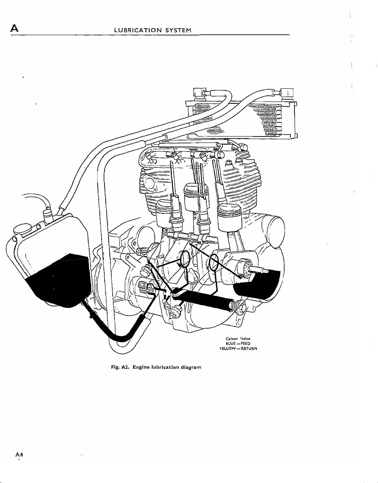
Fig. A2.
Engine
lubrication
diagram
Ccl<~ur
IndIO>:
BLUE_FEED
YELLOW-RETURN
LUBRICATION
ClassicBike.biz
SYSTEM
A
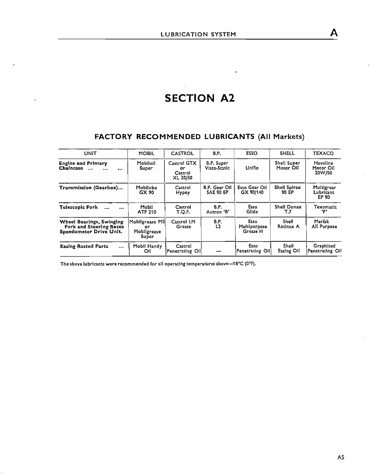
FACTORY
UNIT
Engine and Primary
Chaincase
Transmission (Gearbox)... Mobllube
Telescopic
Wheel
Fork and
Speedometer
Easing Rusted Parts
The
above lubricants
".
..,
Fork
...
Bearings, SwingIng
Steerl
ng Races
DrIve
Unit.
were
RECOMMENDED
MOBIL
Mobil
...
.
..
MobJlgrease
...
recommended
011
Super
90
GX
Mobil
ATF
210
or
Mobllgrease
Super
Mobil
Handy Castrol
011
for all operating temperatures
SECTION
CASTROL
I
Castrol GTX
or
Castrol 20W/50
XL
20/50
Castrol
Hypoy
A2
LUBRICANTS
B.P.
B.P.
Super
Vlsco.Static
B.P.
Gear
011
SAE90EP
Esso Gear Oil Shell
GX
Esse
Unlflo
90/140
(All
Markets)
SHELL
Shell Super Havollne
Motor
011
Spira><
90
EP
I
Castrol
T.Q.F.
MS
Castrol
Grease
Penetrating Oil
LM
B.P.
Autron
B.P.
L2
-
above--18QC
'B'
Es,o
Glide
Es,o
Multipurpose Retlnax A
Grease
Es,o
Penetrating
(O:F).
Shell Donax Texomatlc
T.7
Shell
H
all
Shell Graphlted
Easing
Oil Penetrating
TEXACO
Motor
Hultlgrear
lubricant
EP
90
'F'
Marrak
All
Purpose
all
011
AS
A
ClassicBike.biz
LUBRICATION
SYSTEM
ENGINE
The
engine lubrication systemIsof
type
utilising a duplex gear pump and
the
tank
to
by gravity from
pressure
cartridge
shaft
whenceitescapes and lubricates
outer
parts.
crankcase
an anti-drain valve situated behind
The
shaft is controlled
After
mission,
from
the
feed pump, allIsforced via a
type
filter
to
the
Inner main bearings and big ends,
main bearings, and
all
Is
prevented from draining
when
the
all
pressure
lubricating
the
between
by
the
all drains
through
engineIsstationarybymeans
a release valve.
engine and primary
through
the
drillingsInthe
other
the
pump and
a filtertothe
SECTION
the
the
pump.
the
cylinder walls,
Internal
the
pump.
the
LUBRICATION
dry
ollis
Under
crank-
engine
into
crank-
sump
fed
the
of
trans-
sump,
whereitIs
all
designed so
pumping capacity than the feed gears, thus ensuring
that
The
taken from a connection situated
scavenge sideofthe
lubricating
rocker
afterwards
and Into
scavenged. The timing idler pinion bearing
lubricatedbyoil draining through a drillingInthe
right
A3
SYSTEM
returnedbythe
coolertothe
the
sump remains dryatall
all feedtothe
boxesbywayofgroovesInthe
side crankcase.
all tank. The all pump has been
that
the
scavenge gears have a
valve operating mechanism
pump and
the
rocker
spindles,
draining down
the
sump, whence itIssubsequently
the
scavenge pump via
greater
times.
between
the
all cooler.
the
ollisfed
push rod
into
rocker
cover
the
Is
the
After
the
arms,
tubes
is
SECTION
CHANGING
The
allInneW
changed
1,500 kms) Intervals during
and
thereafterasstatedInSection A1.
It
Is
advisabletodrain
warmasIt will fiow more readily.
When
the
the
wire
(kerosene) and
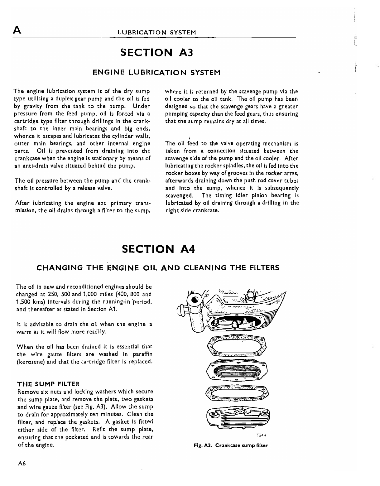
THE
SUMP
Remove six nuts and locking washers which
the
sump plate, and remove
and
wire
to
drain for approximately
filter, and replace
either
ensuring that the pocketed endistowards
of
the
engine.
and reconditioned engines should be
at
250, 500 and 1,000 miles (400, 800 and
oil
has
been drained ItIsessential
gauze filters
that
FILTER
gauze filter (see
sideofthe
THE
the
are
the
cartridge
Fig.
the
gaskets. A gasketIsfitted
filter. Refit
ENGINE
the
running-In 'perlod,
all when
the
A3). Allow
ten
the
washed
filterIsreplaced.
plate,
minutes. Clean
the
sump
In
two
engine
paraffin
secure
gaskets
the
sump
plate,
the
OIL
that
the
rear
A4
AND
Is
CLEANING
Fig. A3. Crankcase sump filter
THE
FILTERS
A6
THE
ClassicBike.biz
OIL
TANK
Open
the
twin
seat
and
Piace a
tray below
allow approximately
drain. Disconnect
unscrew
the
thoroughlyinclean
the
drain plug.
ten
the
large hexagonal headed filter. Wash
kerosene
Itisadvisable to wash oUt
oil (obtainable from
most
remove
feed line union
the
remove
minutes for
(paraffin).
the
oil
tank
garages)
or,IfthisIsnot
tank
available kerosene (paraffin) will serveasa
However, if thisIsused,
removed from
the
re-filiing with oil. (For
ensure
Interior
the
of the
correct
that all
tank
gradeofoil see
Section A2).
NOTE:
the
of
breather
THE
This filterIsof
renewed every
is
changed.
To remove
headed cap from below
The
top
lineonthe
oil
will
FULL·FLOW
levelinthe
dipstick.
cause
excessive
pipe
duetolackofair
the
disposable
3,000
miles
the
filter,
unscrew
tank
venting
FILTER
(S,OOO
the
should
Further
space.
type
and should be
Km)
the
large hexagonally
forward
LUBRICATION
filler cap.
this and
the
oil
to
nut
and
it
with flushing
substitute
trac~s.
prior
are
to
beupto
addition
through
when
the
the
oil
endofthe
SYSTEM
transmission
the spring, and
THE
NEW
outer
cover (Item 2,
withdraw
EL~MENT
Fig.
the
element.
MUSTBEFinED
A4). Remove
WITH THE
OPEN END INWARDS, OTHERWISE THE
SUPPLY
A
the element. Ensure
Add a small quantityofengine
compartmenc before re-assembllng
Replace
ring sealIsIn
to
cooler
top-up
Special
Internal
add half a
operate
(With
Issuing from
can
apertureonthe
side and It will be necessary
spaceInthe
procedure should also be followed
cycle has
WILLBECUT OFF.
rubber
sealing ringIslocatedatthe
the
spring and cap, ensuring
good
dip-stick level, and
has
been
removed,
the
tank
afcer
Note:
parts,
the
the
be Inserted
To
following
pint
of engine oiltothe
starter
Ignition switched off) until allIsseen
the
return
through
frontofthe
tanktoaccommodate
not
been used for an appreciable time.
that
thisIsnot
order.
Replenish
If,
for any reason,
re~check
approximately
ensure
Immediate lubrication of
replacement
pedal
twenty
pipeInthe
the
crankcaseatthe
Inner end of
omitted.
oil
to
the
the
that
the
oil tank
andIfnecessary
five miles.
·of
the
crankcase and
or
thirty
tank.
spark
timing plug
to
allow sufficient
this all.
when
the
filter
filter.
the
the
filters,
times
The
right
motor
A
OIL
'0'
all
oil
This
)8~~'
~~.'i,
.•
@ I
f~
l~~
.
_.~,
•:J'-!tl:,,~...
':;:"i~.:11i;);.~
O\O\l!ii4:=iI1Il\
..
,
..
,."
.
,
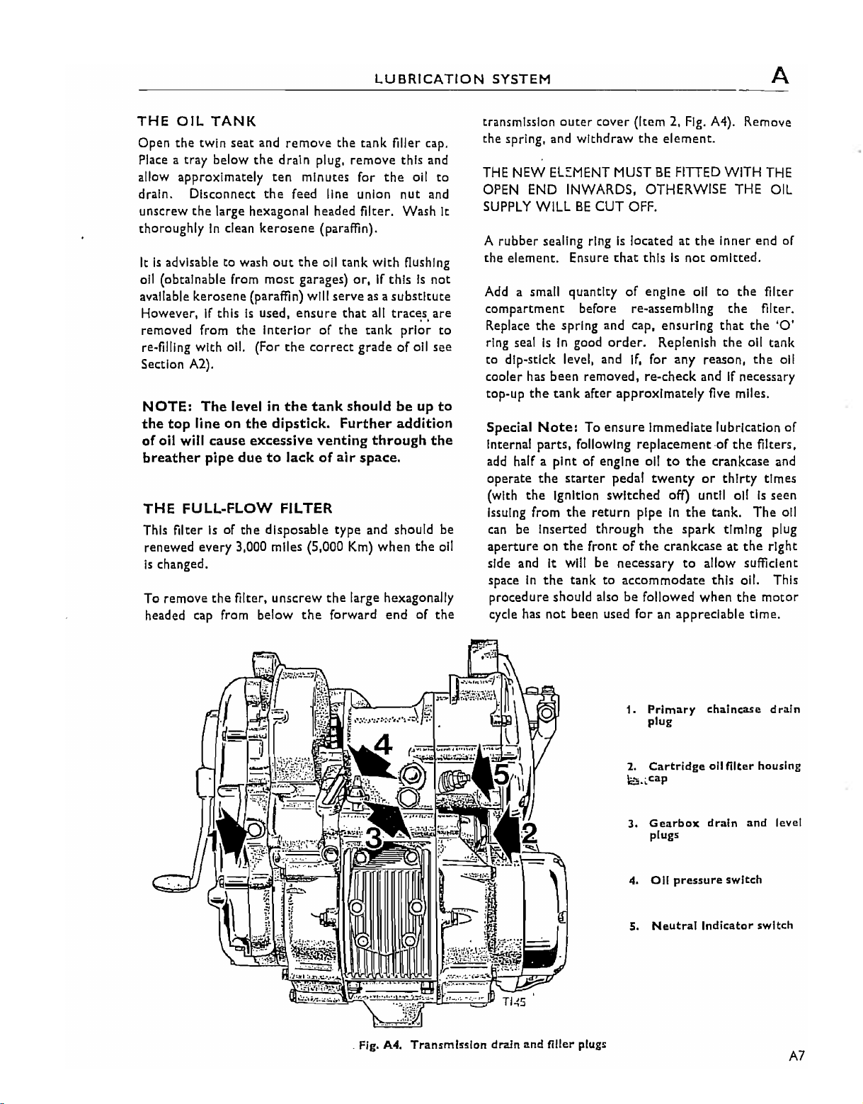
. Fig. A4. Transmfsslon drain and filler plugs
1. Primary chaincase drain
plug
2.
Cartridge
e~
..
cap
3.
Gearbox
4.
5.
plugs
all
Neutral
all
drain and
pressure
Indicator switch
filter
switch
housing
level
A7
A
ClassicBike.biz
LUBRICATION
SYSTEM
SECTION
OIL
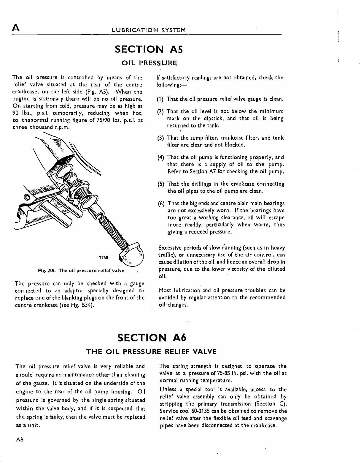
The
011
pressureIscontrolled
relief valve situated at
crankcase,
engineiistationary
On
starting
90 Ibs., p.s.l. temporarily, reducing, when hot,
to
thenormal
three
on
from cold,
thousand
the
running figureof75/90 Ibs. p.s.l.
r.p.m.
the
left side (Fig.
there
pressure
by
means
rear
of
AS).
will be no oil
maybeas high
of
the
centre
When
pressure.
the
the
PRESSURE
If
satisfactory readings are not obtained, check
followlng:-
(1)
That
as
at
(2)
That
mark on
returnedtothe
(3)
That
filter are clean and not blocked.
(4)
That
that
Refer
(S)
That
the
(6)
That
are
too
more readily, particularly when
giving a reduced pressure.
AS
the
oil pressure relief valve gaugeisclean.
the
oil levelIsnot
the
dipstick, and
tank.
the
sump filter, crankcase filter,
the
oil
pumpisfunctioning
thereisa supplyofoil
to
SectionA7for checking
the
drillingsInthe
011
pipestothe
the
big ends and
not
excessively worn.Ifthe
great a working clearance, oil will escape
below
the
that
properly,
to
the
crankcase connecting
oil
pump are clear.
centre
plain main bearings
bearings have
minimum
oil
the
oil pump.
warm,
is
and
the
being
tank
and
pump.
thus
Fig. AS.
The
pressure
connected
replace
centre
The
should
of
enginetothe
pressureIsgovernedbythe
within
the
as
oneofthe
crankcase (see
oil pressure relief valveIsvery reliable and
reqUirenomaintenance
the
gauze. ItIssituated on
the
springIsfaulty, then
a
unit.
The
oil
pressure
can
only be checked with a gauge
to
an
adaptor specially designed
blanking plugs on
Fig.
rear of
valve body, and if ItIssuspected
the
the
reller
valve
the
B34).
THE
oil pump housing. Oil
valve must be replaced
OIL
other
than cleaning
the
undersideofthe
single
spring
Excessive periods
traffic), or unnecessary useofthe
cause dilutionofthe
pressure, duetothe
oil.
to
frontofthe
SECTION
Most lubrication and
avoided
oil changes.
by
regular attentiontothe
A6
PRESSURE RELIEF VALVE
The
spring strengthIsdesigned
valveata pressureof7S·8S lb.
normal running temperature.
Unless a special tool
relief
situated
that
valve assembly
stripping
Service tool 60·2135
relief valve after
pipes have been disconnected
the
of
slow running (such as in heavy
air
control,
oil, and henceanoverall
lower viscosityofthe
oil
pressure
is
available, access
can
primary transmission (Section
can
be obtainedtoremove
the
fiexible oil feed and scavenge
psi.
only be
at
the
troubles
to
drop
diluted
can be
recommended
operate
with
the
to
obtained
crankcase.
oil
can
In
the
at
the
by
C).
the
A8
To
ClassicBike.biz
prevent
tank the ends of
are disconnected.
When the valve has been
domed
thus releasing
drawn.
the
loss-of all from
the
pipes should be pluggedasthey
cap
can be unscrewed from
the
piston which should be with-
the
removed
LUBRICATION
oll.cooler and all
t.he hexagonal
the
main body,
SYSTEM
Thoroughly clean
Inspect for wear.
scoringofpiston, spring fracture, etc.
unit must be replaced.
valve unit into the crankcase,
between
the
all
partsin(kerosene) paraffin and
If
any defectisapparent, e.g.
body and
When
the
screwing
fit
a new fibre washer
crankcase. (Figure
the
the
A
whole
relief
AS).
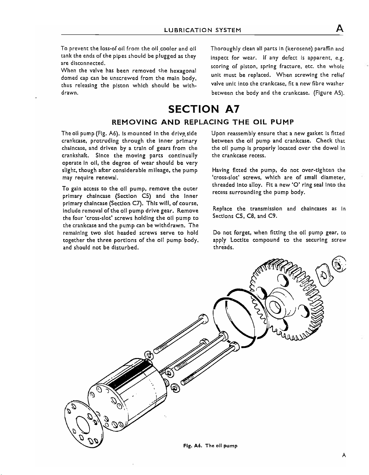
REMOVING
Theall pump (Fig. A6).ismountedInthe
crankcase,
chalncase, and driven
crankshaft. Since
operate
slight, though after considerable mileage.
may
gain
To
primary chalncase (Section
primary chalncase (Section C7). This will,
Include removal of
the four 'cross-slot' screws holding
the crankcase and
remaining
together
and
protruding
In
all,
the
require renewal.
access
to the
two
the
three
should not be
through
byatrainofgears from
the
moving
degreeofwear
011
pump, remove
CS)
the
oil
pump
the
pump
can be
slot
headed screws
portionsofthe
disturbed.
AND
the
Inner
parts
should be very
and
drive gear. Remove
the
withdrawn.
serve
011
SECTION
REPLACING
drlv.e,slde
primary
the
continually
the
pump
the
outer
the
Inner
of
course,
oil pump
pump
to
to
The
hold
body,
A7
THE
Upon reassembly ensure
between
011
the
the crankcase recess.
pumpIsproperly located
Having fitted
Icross~slot'
threaded into alloy. Fit a new
surrounding
recess
Replace
Sections C5,
Do
not forget, when fitting
apply Loctlte compound
threads.
OIL
PUMP
that
the
oil pump and crankcase. Check that
the
pump, do
screws, which areofsmall diameter,
the
pump body.
the
transmission and chalncases
ca,
and C9.
to
a new gasketisfitted
over
the
dowel
not
over-tighten the
'0'
ring seal into the
as
the
all pump gear, to
the
securing screw
In
In
Fig. A6. The all
pump
A9
A
ClassicBike.biz
LUBRICATION
SYSTEM
SECTION A8
REMOVING
To
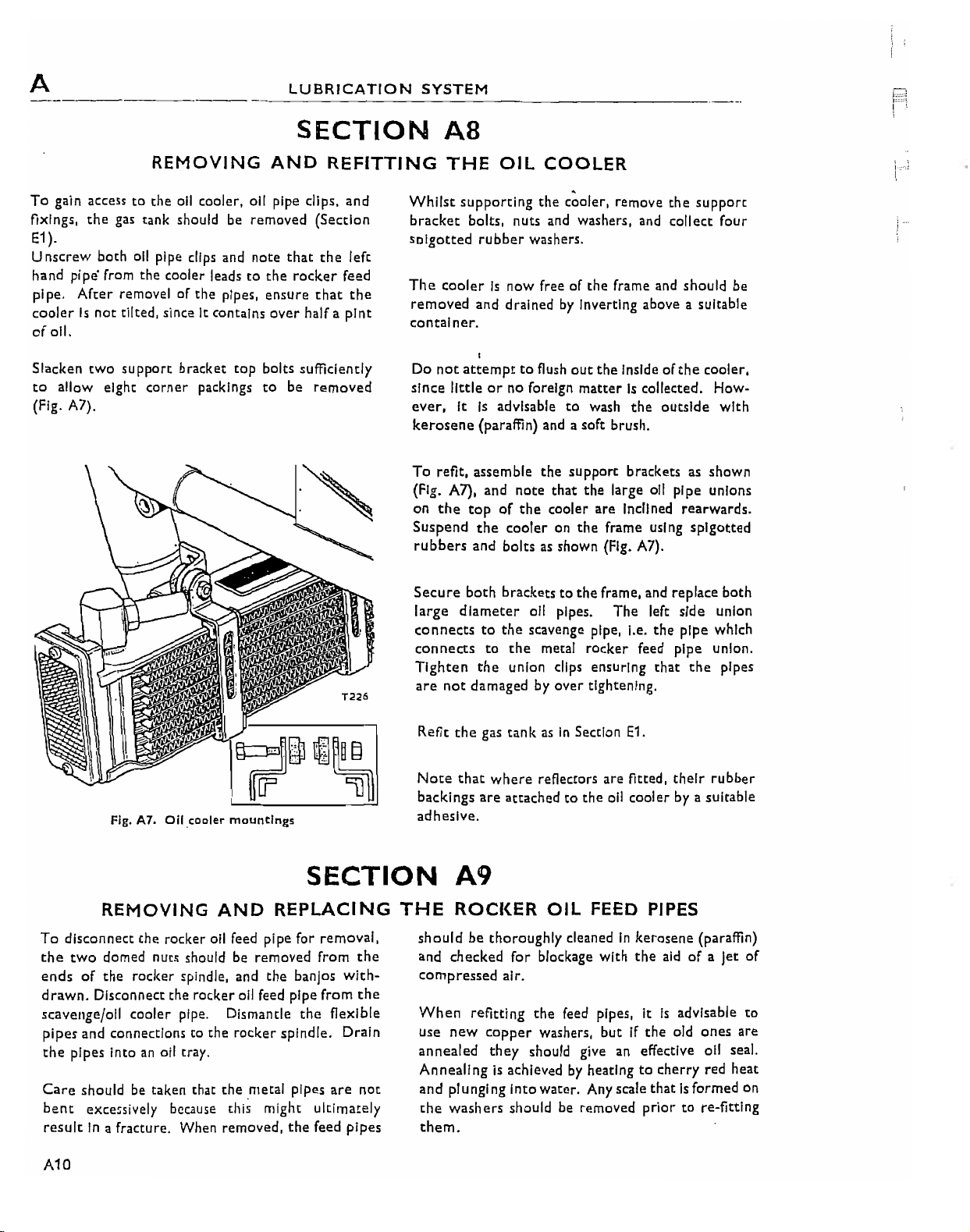
gain accesstothe all cooler, all pipe clips, and
the
Axlngs,
E1
).
Unscrew
hand
pipe.
coolerIsnot
of
all.
Slacken
to
allow eight
(Fig. A7).
gas tank should be removed (Section
both all pipe clips and note
pi
po'
from the cooler leadstothe
After
removel of the pipes,
tilted, sinceItcontains
two
suppOrt bracket
corner
packlngs
AND
that
rocker
ensure
over
top
bolts sUfficiently
to
be
half a
REFITTING
the
left
feed
that
the
pint
removed
THE
Whilst
bracket
solgotted
The
coolerIsnow free of the frame and should be
removed
container.
Do
not
littleorno foreign
since
ever,
kerosene
To
refit, assemble
(Fig. A7), and note
on
the
Suspend
rubbers
Secure
large
connectstothe
connects
Tighten
are
not
OIL
COOLER
supporting
bolts, nuts and washers, and collect four
rubber
and drainedbyInverting above a suitable
I
attempttoflush
It
Is
(paraffin) and a soft brush.
topofthe
the
and bolts as shown (Fig. A7).
both
diameter
to
the
damaged by over tightening.
the
c~oler,
washers.
out
the
matterIscollected. How-
advisable
cooleronthe
bracketstothe
the
union clips ensuring
to
wash
the
support
that
the
cooler are Inclined rearwards.
frame using
frame, and replace both
all pipes.
scavenge pipe, I.e.
metal
rocker
remove
Inside of
the
outside
brackets as shown
large all pipe unions
The
left side union
the
reed pipe union.
that
the
suppOrt
the
cooler,
splgotted
pipe which
the
with
pipes
Fig. A7.
REMOVING
To
disconnect
the
two
domed nuts should be removed from
ends
of
the
drawn.
scavenge/all cooler pipe. Dismantle
pipes and connections to the
the
Care
bent
resultIna fracture. When removed,
A10
Disconnect the rocker all feed pipe from
pipes intoanoil tray.
shouldbetaken that
exce5sively
Oil.cooler
mountings
AND
the
rocker all feed pipe for removal,
rocker spindle, and
because
the
rocker
the
metal
this
might ultimately
SECTION
REPLACING
the
banjos
spindle. Drain
pipes
the
the
flexible
are
feed pipes
with-
the
not
Refit
the
Note
that
backings
adhesive.
gas tankasIn
where
are
attachedtothe
Section
reflectors are fitted,
E1.
all coolerbya suitable
their
A9
THE
ROCKER
shouldbethoroughly cleanedInkerosene (paraffin)
checked
and
compressed air.
When
Use
annealed
Annealing
and
the
them.
refitting
new
copper
they
is
piunglngI
washers
OIL
FEED PIPES
for
blockage with
the
feed pipes, ItIsadvisable
washers, butIfthe
should give an effective all seal.
achievedbyheatingtocherry
nto
water. Any scale
should be removed priortore-fittlng
the
aidofa Jet
old
ones
red
thatIsformed on
rubber
of
to
are
heat
LUBRICATION
ClassicBike.biz
SYSTEM
SECTION AIO
A
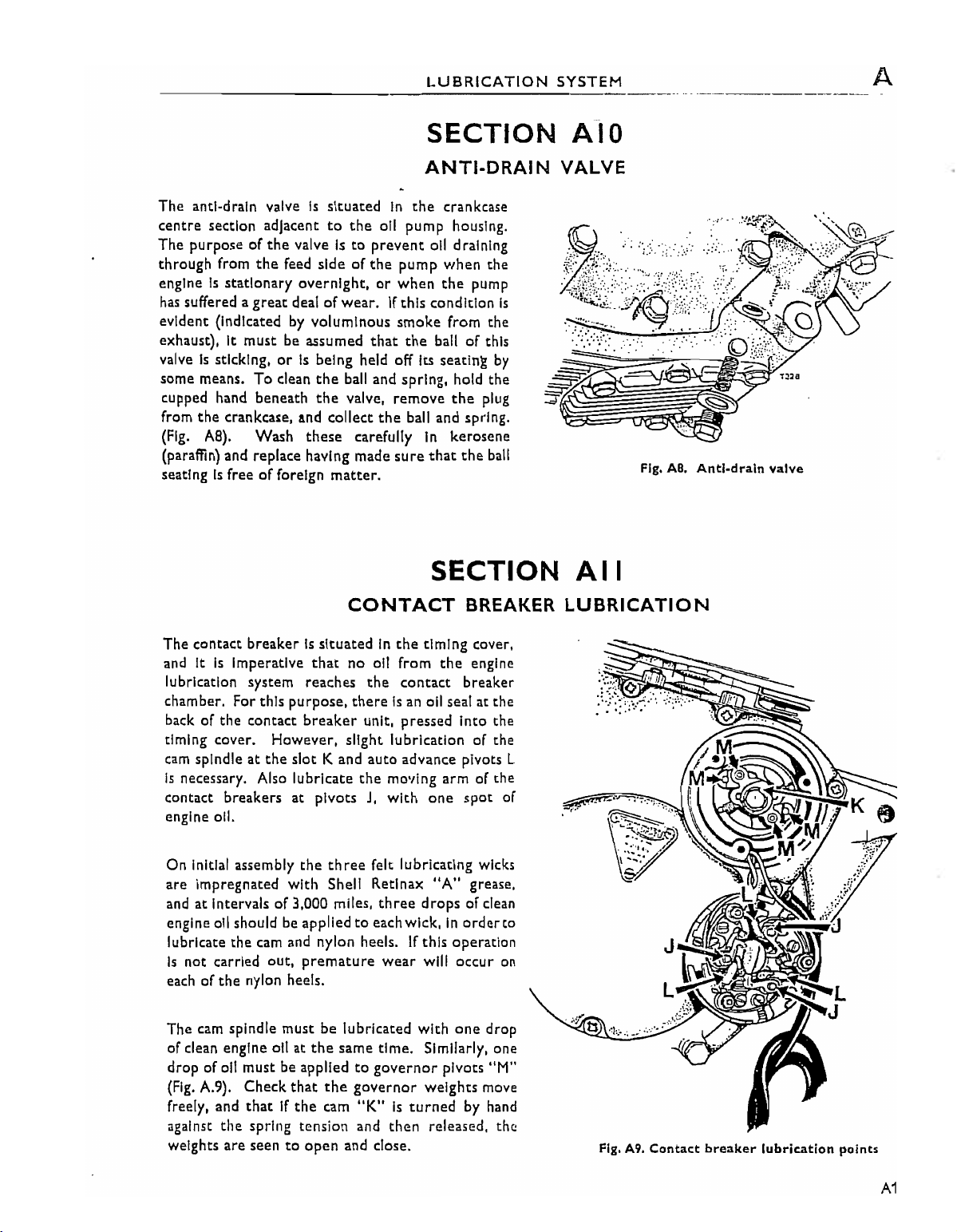
The
anti-drain valveIssituated
centre
The purpose of
through from
engine
evident (Indicatedbyvoluminous
exhaust), It
some means.
section adjacent
the
the
Is
stationary
has
suffered a
valve
Is
cupped hand beneath
from
the
(Fig.
(paraffin) and replace having made
seatingIsfreeofforeign
great
must
sticking,orIs
To
clean
crankcase, and collect
AS).
Wash
to
the
valveIsto
feed side of
overnight,orwhen
deal of
be assumed
being held off Its seating
the
the
these
prevent
the
wear.Ifthis condition
that
bail and spring, hold the
valve,
carefully
matter.
CONTACT
ANTI-DRAIN
In
the
crankcase
oil pump housing.
oil draining
pump
when
the
the
pump
smoke
remove
the
sure
from the
the
ballofthis
the
plug
ball and spring.
In
kerosene
that
the
bail
SECTION
BREAKER
by
VALVE
Is
Fig.
AB.
Anti-drain
valve
All
LUBRICATION
The contact
and It
lubrication system reaches
chamber. For this purpose,
back of the contact
timing cover. However, slight lubrication of the
cam
spindleatthe
Is
necessary. Also lubricate
contact breakers at pivotsJ,with
engine
On Initial assembly
are
Impregnated with Shell Retlnax
and
at
engine oil should be appliedtoeach wick,Inordereo
lubricate
Is
not carried out, premature
each of
The cam spindle must be lubricated with
of clean engine oilatthe
drop of oil must be appliedtogovernor
(Fig.
A.9). Check
freely, and
against
weights
breakerIssituatedInthe
Is
Imperative
011.
Intervals of3,000 miles,
the
cam and nylon heels.Ifthis operation
the
nylon heels.
thatIfthe
the
spring tension and
are
seentoopen
that
breaker
slot
the
that
no
oil from
the
contact breaker
thereIsan oil seal at the
unit, pressed Into the
K and
auto
advance pivots L
the
moving
three
felt lubricating wicks
three
wear
same time. Similarly, one
the
governor
cam
"K"Isturned
then
and close.
timing cover,
the
engine
arm
of the
one
spot
"A"
grease.
drops
of clean
will occur
one
drop
pivots "M"
weights
released. the
move
by hand
of
on
Fig. A9.
Contact
breaker
lubrication
points
A11
 Loading...