

Triumph TR6 1976 Handbook

RIU
TRIUMPH TR6
HANDBOOK
i
'
I
i
l
ROVER
ROVER TRIUMPH SERVICE
Coventry CV4 9DB
England
JAGUAR and ROVER TRIUMPH Parts and Accessories
P.O. Box 150, Coventry CV4 9DB
England
BRITISH LEYLAND MOTORS INC.
600 Willow Tree Road
Leo~ia, N.J. 07605
BRITISH LEYLAND MOTORS CANADA LTD.
P.O. Box 5033, 4445 Fairview Street
Burlington
Ontario L7R 4A3
Canada
TRIUMPH
SALES
or
Publication Part No. 545111176
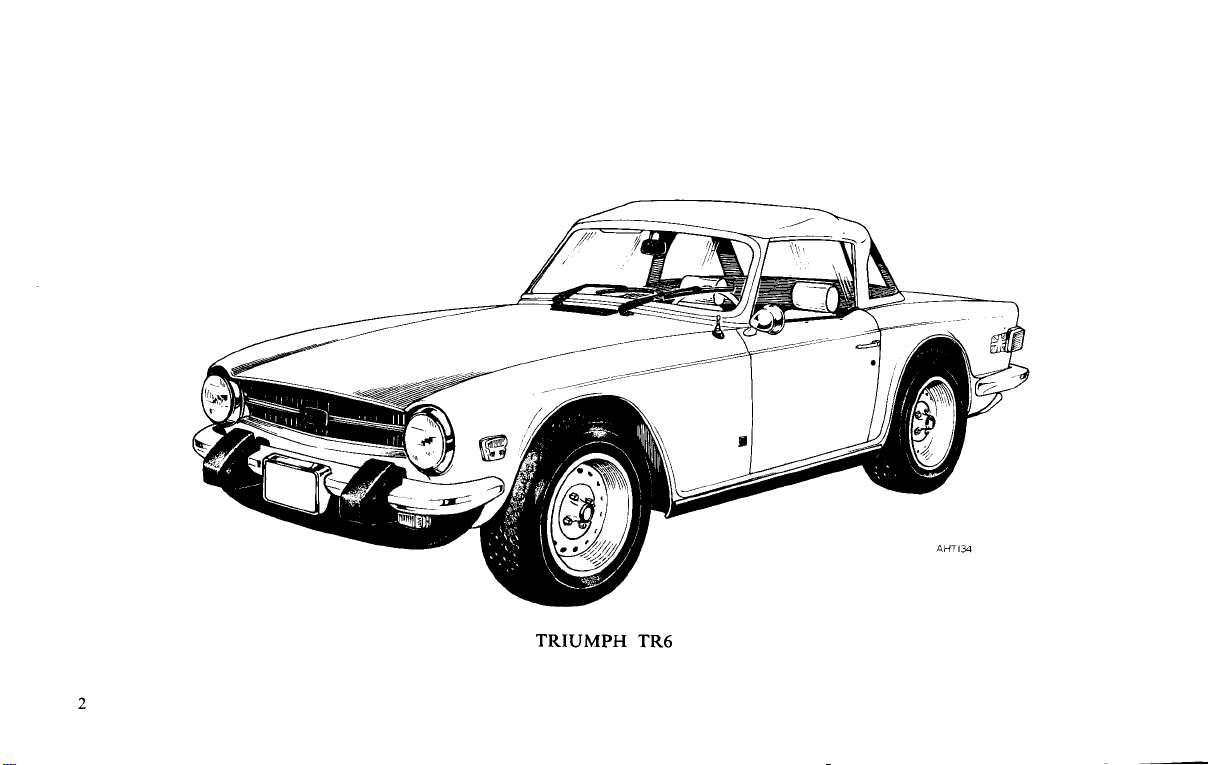
TRIUMPH TR6
Introduction
Dmmm
your TR6 embodies inany new safety features, the very presence of which will
Read carefully the contents of tlk book ivl~ich gives, ill the simplest
possible terms, information vital
The TR6 complies
and State Regulations concerning Safety, Engine Crankcase Emission and
of
Because
these regulations, owners ure strongly urged to read the Emission
Control System, Maintenance and Wurlmlty i~lformation in this handbook.
AND
BUILT
to give long and co~lsistent trouble-jke service,
add to your conjidence.
!o the proper operation, care and regular
maintenance of the car.
with, and in many cases exceeds, all current Federal
Fuel Evaporative Control.
The operations carried out by your Dealer will be in accordance
with the current recommendations and may be subject to
r'ei'ision from time to time.
These publications should be passed to each subsequent owner of
the vehicle and the Servicing
vehicle is kept within the Federal limits in respect of the
Details completed to ensure that the
Clean Air Act.
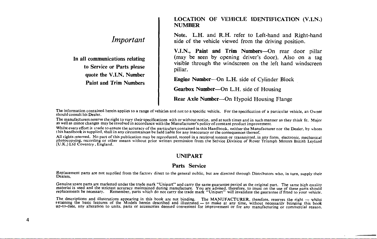
LOCATION OF VEHICLE IDENTIFICATION (V.I.N.)
I
NUMBER
Note.
L.H.
and
R.H.
Important
In all communications relating
to Service or Parts please
quote the V.I.N. Number
Paint and Trim Numbers
The information contained herein applies to a range of vehicles and not to a specific vehicle. For the specification of a particular vehicle, an Owner
should consult his Dealer.
The manufacturers reserve the right to vary their specifications with or without notice, and at such times and in such manner as they think fit. Major
as wellas minor changes may be involved in accordance with the Manufacturer's policy of constant product improvement.
Whilst every efforl is oade to ensure the accuracy of the particulars contained
this handbook is supplied, shall in any circumstances be held ],able for any inaccuracy or the co&equences thereof.
All rights reserved. No part of this publication may be reproduced, stored in a retrieval system or transmitted. in any form electronic mechanical
photocopying, recording or other means without prior written permission from the Service Division
(U.K.) Ltd Coventry, England.
Replacement parts are not supplied from the factory direct to the general ~ublic, but are directed through Distributors who, in turn, supply their
Dealers.
Genuinespare parts are marketed under the trade mark "Unipart" and carry the same guarantee period as the original part. The same high quality
material is used and the strictest accuracy maintained during manufacture. You are advised, therefore, to ins~st on the use of these parts should
replacements be necessary. Remember, parts which do not carry the trade mark "Unipart" will invalidate the guarantee if fitted to your vehicle.
The descriptions and illustrations appearing in this book are not binding.
retaining the basic features of the Models herein described and illustrated
up-to-date, any alteration to units. parts or accessories deemed convenient for improvement or for any manufacturing or commercial reason.
I
side of the vehicle viewed from the driving position.
V.I.N., Paint and Trim Numbers-On rear door pillar
(may be seen by opening driver's door). Also on
visible through the windscreen on the left hand windscreen
~illar.
Engine Number-On
Gearbox Number-On L.H. side of Housing
I
-
Rear Axle Number-On Hypoid Housing Flange
I
in
this Handbook neither the Manufacturer nor the Dealer, by whom
UNIPART
Parts Service
The MANUFACTURER therefore, reserves the right
-
to make at any time, hhout necessarily brin@ng this book
refer to Left-hand and Right-hand
L.H.
side of Cylinder Block
of
Rover Triumph 'Motors ~riish Leyland
-
a
whilst
tag
Page
List
Sect ions
Introduction
Location of unit numbers
Controls. Instruments and Indicators
Safety Harness
Seats
Locks and Keys
Soft Top
Hwd
Top .
Care of Bodywork
Wheel
Cooling System
Electrical System
Driving Recommendations
Routine Servicing
Emission and Control Evaporative System .
Periodic Checks
Regular Maintenance
Lubrication Specification . .
Windshield Wipers
General Specification
.
. . . . . . .
.
. .
.. . . . . .
. .
. . .
.
. . . . .
. . .
and Tires . .
. .
. .
.
. .
. .
.
.
.
.
. . .
.
.
.
. . .
. . .
. .
.
.
.
.
.
. .
. .
.
.
. . . .
. . .
.
. .
.
. .
. . .
.
.
.
.
.
.
. . .
. . . .
.
.
.
.
.
. . . . . . .
. . .
.
.
.
. .
..
.
. . .
.
.
.
.
.
.
.
. . . .
. . .
.
.
.
. .
.
. . . . . 28
.
.
. . .
.
. . .
.
. . .
.
.
.
. .
.
.
.
.
. .
.
. .
.
. . .
.
. . .
. .
. . .
..
..
.
.
.
. . 16
.
. 18
.
.
.
.
.
. . 25
.
.
.
.
.
.
. 66
. . . 67
.
.
.
.
.
.
3
4
6
14
15
20
21
22
37
39
40
49
51
68
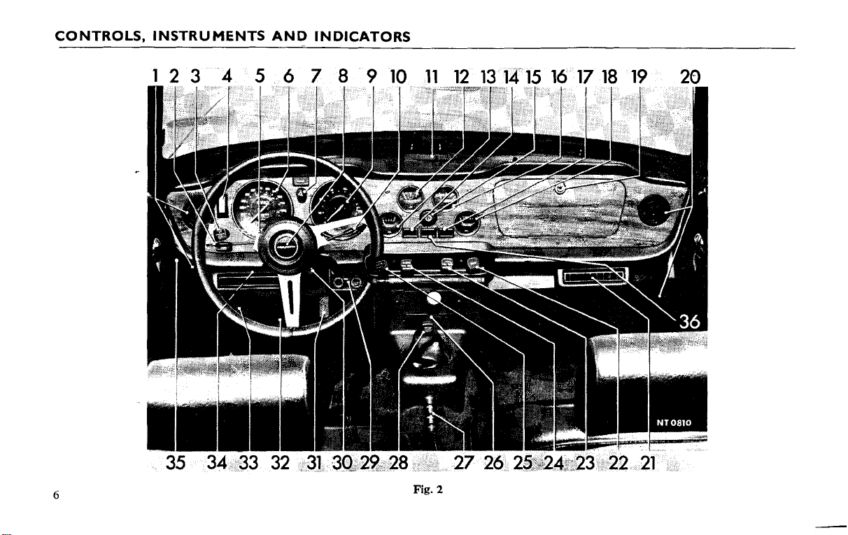
CONTROLS, INSTRUMENTS AND INDICATORS
3
32
Fig.
2
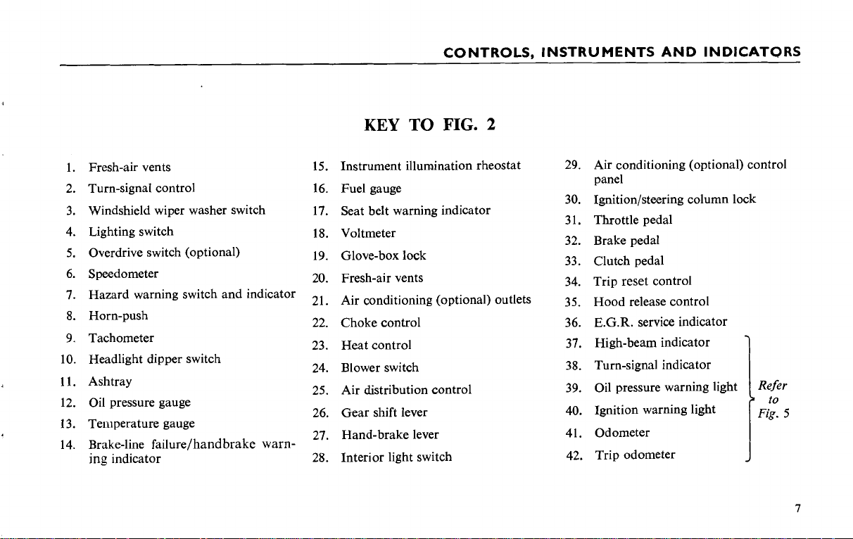
CONTROLS, INSTRUMENTS AND INDICATORS
KEY
Fresh-air vents
Turn-signal control
Windshield wiper washer switch 17. Seat belt warning indicator
Lighting switch
Overdrive switch (optional)
Speedometer
Hazard warning switch and indicator
Horn-push
Tachometer
Headlight dipper switch
Ashtray
Oil pressure gauge
Temperature gauge
Brake-line failure/handbrake warn-
ing indicator
15.
Instrument illumination rheostat
16.
Fuel gauge
Voltmeter
Glove-box lock
Fresh-air vents
Air conditioning (optional) outlets
Choke control
Heat control
Blower switch
Air distribution control
Gear shift lever
Hand-brake lever
Interior light switch
TO
FIG.
2
Air conditioning (optional) control
panel
Ignitionlsteering column lock
Throttle pedal
Brake pedal
Clutch pedal
Trip reset control
Hood release control
E.G.R. service indicator
High-beam indicator
Turn-signal indicator
Oil pressure warning light
Ignition warning light
Odometer
Trip odometer
to
Fig.
5

CONTROLS, INSTRUMENTS AND INDICATORS
CONTROLS, INSTRUMENTS AND INDICATORS
The controls, instruments and indicators shown on Figs. 2 and 6 and described in the following pages are positioned within easy
reach of the driver to afford maximum ease of operation and minimum distraction. The bracketed figures in the text cross-refer with
the key on page
7.
Fresh-Air Vents (1)
The swivelling vents can be adjusted to admit cold air only
in
any chosen direction within the limits of movement. Each vent
incorporates a valve, operated by a knob in the center of the
vent. To diminish or shut off the supply of air, turn the knob
clockwise. The air flow may be boosted by use of the blower
motor (See item 24).
Turn
Signal Control
Move the control lever upwards to operate the right-hand
turn-signal lights or downwards to operate the left-hand turnsignal lights.
Windshield Wiper/Washer Switch
Depress the switch to spray clean fluid onto the windshield and
release the switch when sufficient fluid has been dispensed.
Turn the switch clockwise to operate the wipers at slow speed
and turn the switch clockwise again to operate the wipers at high
speed. Turn the switch fully anticlockwise to switch the wipers
off, when they will automatically return to the parked position
at the base of the windshield.
See
(2)
(38)
Page 1
3.
The wipers and washer will only operate when the ignition
switch is turned 'ON'.
Lighting Switch (4)
Depress the lower portion of the switch to the first position
to illuminate the tail, license plate, parking lights and side
marker lights.
Depress the switch again to the second position to illuminate
the headlights. (See "Headlight Dipper", 10).
(5)
Overdrive Switch
When an overdrive unit is fitted to the vehicle the operating
switch is mounted on the left-hand side of the steering column.
Move the lever up to engage the overdrive and down to release
it. Before using the control, refer to page
Speedometer (6)
Additional to indicating the road speed of the vehicle in
miles
and kilometres per hour, the instrument also combines the
turn signal and high beam warning lights and the total and trip
odometers.
(Optional)
38.
CONTROLS, INSTRUMENTS AND INDICATORS
i
Hazard Warning Switch and Indicator (7)
If the vehicle is immobilised and constitutes a hazard to other
vehicles, warning may be given by using the "hazard warning
system". To operate, pull the switch (7) when all turn-signal
lights will flash intermittently.
When the hazard switch is operated, a bulb in the switch will
flash in unison with the exterior warning lamps.
Horn Push (8)
Press to operate the horns.
Oil Pressure Gauge (12)
Oil pressure at 2,000
tions, should
such
as
be
competition work, may cause the oil pressure to drop
45-65 Ibs./sq. in. Severe operating conditions,
r.p.m. under normal operating condi-
below 25 lb./sq. in., indicating that the oil temperature is
excessive. Under these circumstances fitment of an oil cooler may
be
necessary.
Temperature Gauge
(1
3)
When the ignition switch is turned 'ON' the pointer moves
slowly across the dial taking up to one minute to reach a true
Tachometer
The tachometer indicates the engine speed in revolutions per
minute and combines two warning indicators (39,40. See Fig. 5).
The speed range within the colored segments is subject to the
"Recommended Speed Limits" mentioned on page 38.
Headlight Dipper Switch (10)
When the headlights are illuminated (see 'Lighting Switch' on
page
To return to the high beam position, move the lever up.
The high beam position is indicated by a blue warning light
(37) near the bottom of the speedometer dial.
Lifting the lever towards the steering wheel flashes the headlight high beams.
(9)
S),
the high beams may be lowered by moving the lever down.
reading.
Normal operating temperature is reached when the pointer
registers in the central sector of the dial. Should the pointer reach
the highest mark, stop the engine immediately and check the
level of coolant
the radiator. Refer to page
49.
in
Brake-line Failure/Handbrake Warning Indicator (14)
When the ignition switch is turned on the "brake line failure"
and "low oil pressure" indicator lights glow faintly and are
extinguished when the engine is running. Should failure of the
front or rear brake lines occur, the indicator (14) will glow
brightly.
A
broken bulb filament is indicated by the warning light
failing to glow when the ignition is turned on, before starting the
engine.
(1
Ashtray
1)
An ashtray is provided
in
the center of the facia top. To
empty, lift the assembly from the surround.
The warning light will also glow brightly, as a reminder to
the driver, when the handbrake is applied, provided that the
ignition switch is "ON".
9
CONTROLS, INSTRUMENTS AND INDICATORS
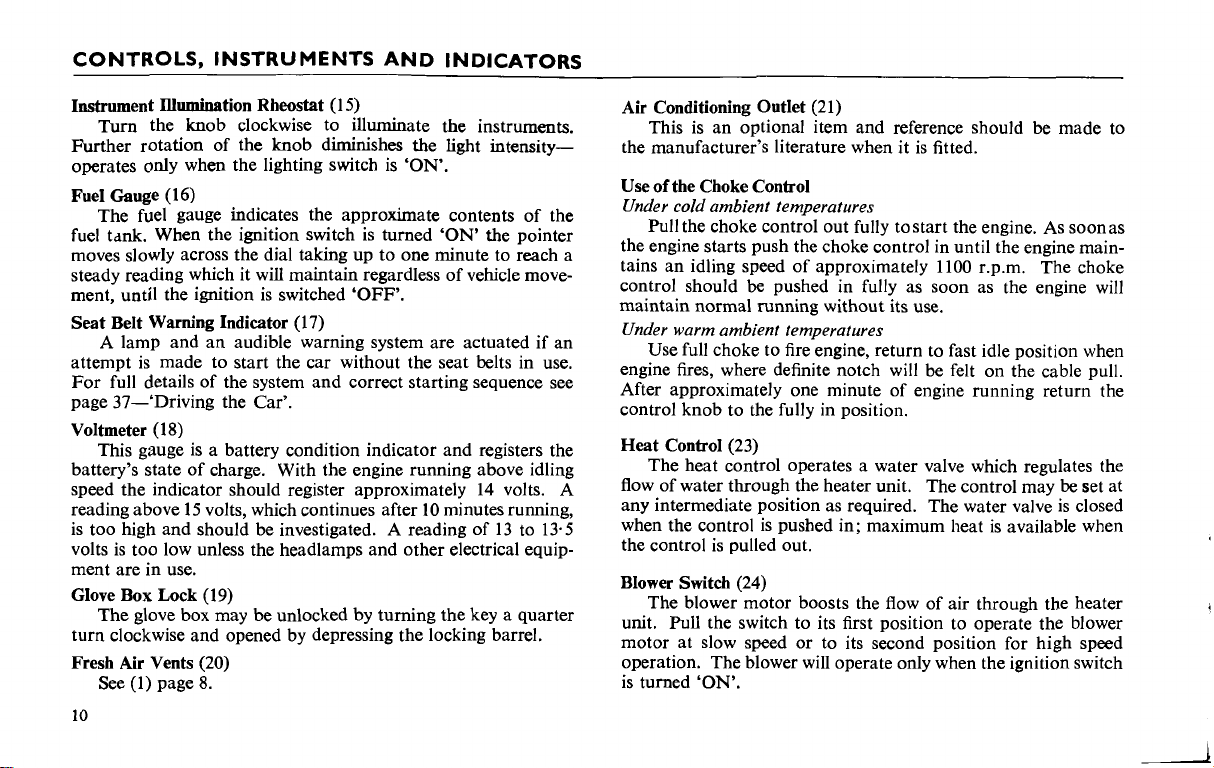
Instrument Illumination Rheostat
Turn the knob clockwise to illuminate the instruments.
Further rotation of the knob diminishes the light intensityoperates only when the lighting switch is
Fuel Gauge
The fuel gauge indicates the approximate contents of the
fuel tdnk. When the ignition switch is turned
moves slowly across the dial taking up to one minute to reach a
steady reading which it will maintain regardless of vehicle movement, until the ignition is switched
(1
6)
Seat Belt Warning Indicator
A lamp and an audible warning system are actuated if an
attempt is made to start the car without the seat belts in use.
For full details of the system and correct starting sequence see
page 37-'Driving the Car'.
Voltmeter
battery's state of charge. With the engine running above idling
speed the indicator should register approximately 14 volts.
reading above 15 volts, which continues after
is too high and should be investigated. A reading of 13 to 13-5
volts is too low unless the headlamps and other electrical equipment are in use.
Glove Box Lock
turn clockwise and opened by depressing the locking barrel.
Fresh Air Vents
(1 8)
This gauge is a battery condition indicator and registers the
(1
The glove box may be unlocked by turning the key a quarter
See (1) page 8.
9)
(20)
(17)
(1 5)
'OFF'.
'ON'.
'ON'
10
minutes running,
the pointer
A
Air Conditioning Outlet
This is an optional item and reference should be made to
the manufacturer's literature when it is fitted.
(21)
Use of the Choke Control
Under cold ambient temperatures
Pull the choke control out fully tostart the engine. As soonas
the engine starts push the choke control in until the engine maintains an idling speed of approximately
control should
maintain normal running without its use.
Under warm ambient temperatures
Use full choke to fire engine, return to fast idle position when
engine fires, where definite notch will be felt on the cable pull.
After approximately one minute of engine running return the
control knob to the fully in position.
Heat Control
The heat control operates a water valve which regulates the
flow of water through the heater unit. The control may
any intermediate position as required. The water valve is closed
when the control is pushed in; maximum heat is available when
the control is pulled out.
Blower Switch
The blower motor boosts the flow of air through the heater
unit. Pull the switch to its first position to operate the blower
motor at slow speed or to its second position for high speed
operation. The blower will operate only when the ignition switch
is turned
(23)
'ON'.
be
pushed in fully as soon as the engine will
(24)
1100 r.p.m.
The choke
be
set at
CONTROLS, INSTRUMENTS AND INDICATORS
Air
Distribution
i
The air distribution control operates a 'flap' valve which
directs air from the heater unit to the windshield or to the
windshield and interior. The maximum volume of air is
directed to the windshield (for demisting and
when the control is pulled halfway out. When the control is
pulled fully out, air is distributed to the interior and to the windshield. The 'flap' valve is closed when the control is pushed fully in.
Gear
Shift
Moving the gear shift lever from neutral, the gear positions
are as follows
1st
2nd
3rd
4th (top)
Reverse
Always select neutral before starting the engine.
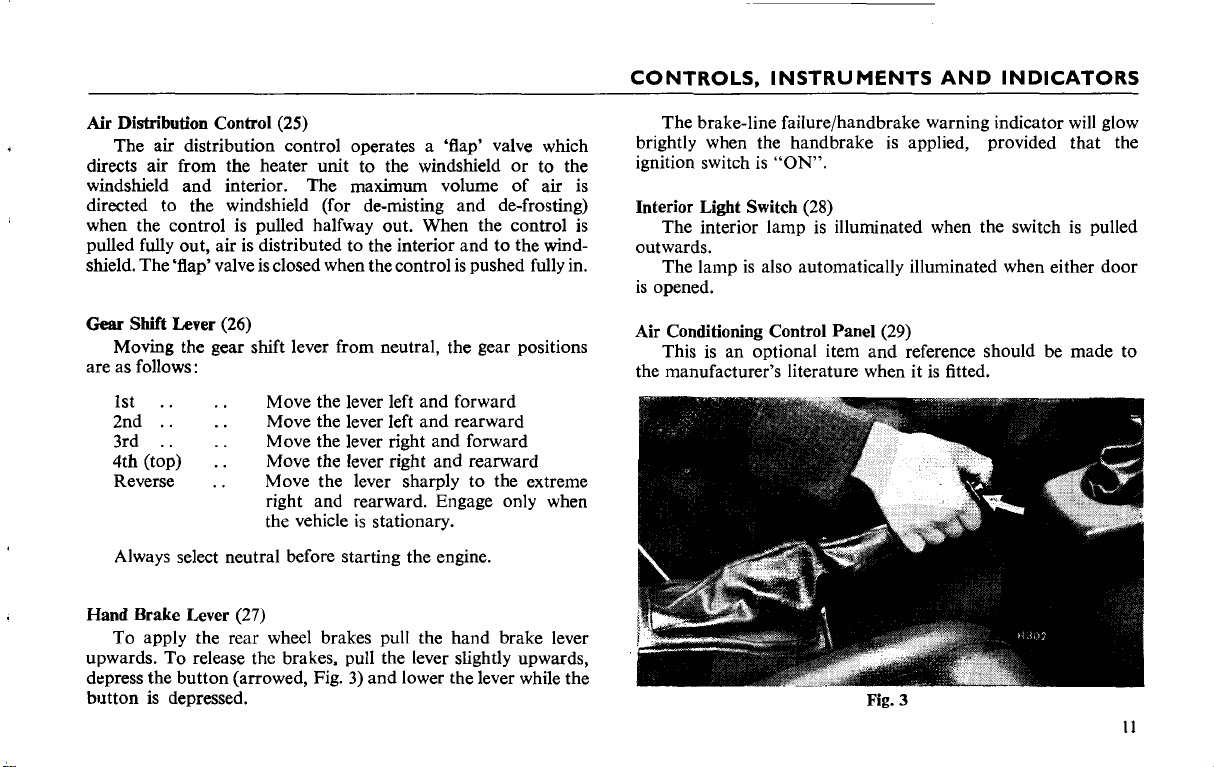
Hand Brake Lever
To apply the rear wheel brakes pull the hand brake lever
upwards. To release the brakes, pull the lever slightly upwards,
depress the button (arrowed, Fig. 3) and lower the lever while the
button is depressed.
Lever
.
. .
.
.
. .
Control (25)
(26)
:
.
.
.
. .
.
.
.
.
(27)
de-frosting)
Move the lever left and forward
Move the lever left and rearward
Move the lever right and forward
Move the lever right and rearward
Move the lever sharply to the extreme
right and rearward. Engage only when
the vehicle is stationary.
The brake-line failurelhandbrake warning indicator will glow
brightly when the handbrake is applied, provided that the
ignition switch is
Interior Light Switch (28)
The interior lamp is illuminated when the switch is pulled
outwards.
The lamp is also automatically illuminated when either door
is opened.
Air Conditioning Control Panel (29)
This is an optional item and reference should be made to
the manufacturer's literature when it is fitted.
"ON".
Fig.
3
11
CONTROLS, INSTRUMENTS AND INDICATORS
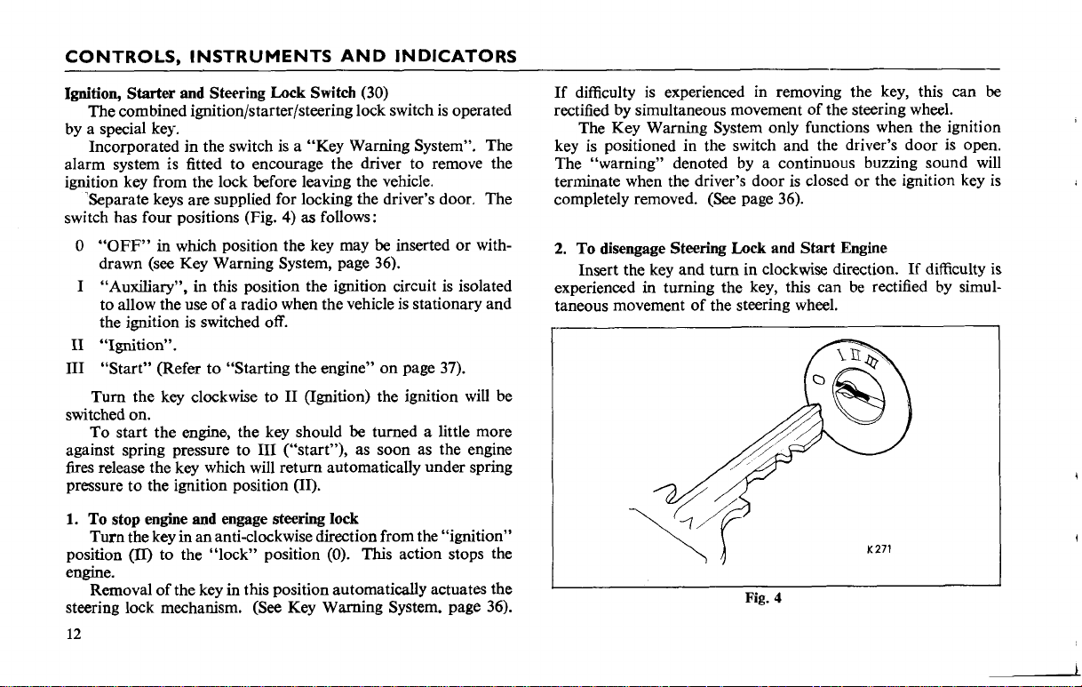
Ignition, Starter and Steering Lock Switch (30)
The combined
ignitionlstarterlsteering
lock switch is operated
by a special key.
Incorporated in the switch is a "Key Warning System". The
alarm system is fitted to encourage the driver to remove the
ignition key from the lock before leaving the vehicle.
-Separate keys are supplied for locking the driver's door. The
4)
as
switch has four positions (Fig.
0
"OFF"
in which position the key may be inserted or with-
follows:
drawn (see Key Warning System, page 36).
I "Auxiliary", in this position the ignition circuit is isolated
to allow the use of a radio when the vehicle is stationary and
the ignition is switched off.
I1
"Ignition".
I11 "Start" (Refer to "Starting the engine" on page 37).
Turn the key clockwise to
I1 (Ignition) the ignition will be
switched on.
To start the
engine,
against spring pressure to
the key should be turned a little more
I11
("start"), as soon as the engine
fires release the key which will return automatically under spring
pressure to the ignition position (II).
1.
To stop engine and engage steering lock
Turn the key in an anti-clockwise direction from the "ignition"
(II)
position
to the "lock" position (0). This action stops the
engine.
Removal of the key in this position automatically actuates the
steering lock mechanism. (See Key Warning System. page 36).
If difficulty is experienced in removing the key, this can
rectified by simultaneous movement of the steering wheel.
The Key Warning System only functions when the ignition
key is positioned in the switch and the driver's door is open.
The "warning" denoted by a continuous buzzing sound will
terminate when the driver's door is closed or the ignition key is
(See
completely removed.
2.
To disengage Steering Lock and Start Engine
page 36).
Insert the key and turn in clockwise direction. If difficulty
experienced in turning the key, this can be rectified by simultaneous movement of the steering wheel.
I
Fig.
4
be
is
I
CONTROLS, INSTRUMENTS AND INDICATORS
t
These are conventional items which should require no further
explanation.
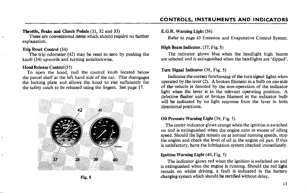
Trip Reset Control
The trip odometer
'Ihroffle, Brake
(34)
knob
Hood Release Control
To open the hood, pull the control knob located below
the parcel shelf at the left hand side of the car. This disengages
the locking plate and allows the hood to rise sufficiently for
the safety catch to be released using the fingers.
and
Clutch Pedals
(34)
(42)
may
(31, 32
and
be
reset to zero by pushing the
upwards and turning anticlockwise.
(3 5)
33)
See page
17.
E.C.R. Warning Light
Refer to page
High Beam Indicator.
(36)
43
Emission and Evaporative Control System.
(37,
Fig,
5)
The indicator glows blue when the headlight high beams
are selected and is extinguished when the headlights are 'dipped'.
(38,
Fig.
Turn Signal Indicator
Indicates the
correct
operated by the lever
(2).
5)
functioning of the turn signal lights when
A
broken lilament in a bulb on one side
of the vehicle is denoted by the non-operation of the indicator
in
light when the lever is
the relevant operating position.
A
defective flasher unit or broken filament in the indicator bulb
will
be
indicated by no light response from the lever in both
directional positions.
Oil Pressure Warning Light
(39,
Fig.
5)
The center indicator glows orange when the ignition is switched
on and is extinguished when the engine runs in excess of idling
speed. Should the light remain on at normal running speeds, stop
the engine and check the level of oil in the engine oil pan. If this
is satisfactory, have the lubrication system checked immediately.
(40,
Fig.
Ignition Warning Light
5)
The indicator glows red when the ignition is switched on and
is extinguished when the engine is running. Should the red light
a
fault
is
indicated in the battery
rectified without delay.
Fig.
remain on whilst driving,
5
charging system which should
be
CONTROLS, INSTRUMENTS AND INDICATORS
Odometer (41, Fig.
The figures within the aperture below the center of the speedometer dial show the total mileage of the vehicle and may be
used as a guide for periodic lubrication and maintenance.
Trip Odometer (42, Fig.
The figures within the aperture above the center of the
speedometer dial may
journey, provided that the figures are initially set at zero. (See
'Trip Zero Control', 34.)
Radio Controls
The radio aeriel fitted to the left front wing is raised by pulling
the protruding tip upwards. The aeriel should always be lowered
before the car is put through an automatic car wash plant.
Two radio speakers are fitted in the facia
tion to an approved radio receiver. Refer to the radio leaflet
supplied with the set for operating instructions.
Sun Visors
Two adjustable sun visors, padded to reduce the risk of
impact injury, may be
and swung to eliminate side glare. The passenger's sun visor
incorporates a vanity mirror.
Rear View Mirror (See page 20)
Safety harness anchorage points are built into the vehicle and
automatic, reel type safety belts are fitted before the car is
delivered.
5)
5)
be
used to record the distance of each
consol for connec-
unclipped from the centre support brackets
SAFETY
HARNESS
Using the Harness
Ensure that the buckle unit is conveniently situated by the
side of the seat and pass the seat buckle over the shoulder nearest
to the car door. With the lap and body belts passing across the
body, plug the belt buckle into the nearest centre buckle unit.
This is denoted by a positive 'click'.
To release the harness depress the marked panel on the centre
buckle unit.
Seat Belt Warning System
The seat belt warning device will operate if an attempt is made
to start the car without the seat belts in use. For full details see
page 37 "Driving the Car".
Cleaning
Badly stained safety belts can be dry cleaned. The cleaner
should be advised of the nature of staining. Belts subjected to
normal soiling can be cleaned with soap, or detergents dissolved
in hot water.
Inertia Reel Mechanism Check
Every 10,000 km
check to ensure that the safety harness inertia reel mechanisms
for both driver and passenger continue to operate satisfactorily.
IMPORTANT. Road tests must only be carried out under
maximum safe road conditions, i.e. level, dry road with no
following or oncoming traffic of any kind.
(a) With the safety harness fitted to driver and passenger as
previously described, start the engine and accelerate the
vehicle to approximately 24
that it is safe to do so, brake sharply.
(6000 miles), carry out the following road
km/h (15 m.p.h.). Ensuring
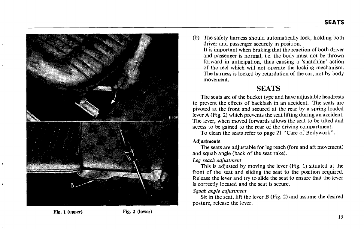
Fig.
2
(lower)
S
EATS
(b) The safety harness should automatically lock, holding both
driver and passenger securely in position.
It is important when braking that the reaction of both driver
and passenger is normal, i.e. the body must not be thrown
forward in anticipation, thus causing a 'snatching' action
of the reel which will not operate the locking mechanism.
The harness is locked by retardation of the car, not by body
movement.
SEATS
The seats are of the bucket type and have adjustable headrests
to prevent the effects of backlash in an accident. The seats are
pivoted at the front and secured at the rear by a spring loaded
A
lever
The lever, when moved forwards allows the seat to be tilted and
access to
Adjustments
and squab angle (back of the seat rake).
Leg reach adjustmerzt
front of the seat and sliding the seat to the position required.
Release the lever and try to slide the seat to ensure that the lever
is correctly located and the seat is secure.
Squab angle adjustment
posture, release the lever.
(Fig. 2) which prevents the seat lifting during an accident.
be
To clean the seats refer to page 21 "Care of Bodywork".
The seats are adjustable for leg reach (fore and aft movement)
This is adjusted by moving the lever (Fig.
Sit in the seat, lift the lever B (Fig. 2) and assume the desired
gained to the rear of the driving compartment.
1)
situated at the
15
LOCKS
AND
KEYS
LOCKS
Keys
The following keys are supplied with each new TR6.
2
Ignition keys.
2
Door keys.
2
Glove locker and trunk locker keys.
In addition, an ignition key identification disc is supplied and
must be submitted to your Triumph dealer when new
ignition keys are required.
ignition keys it should
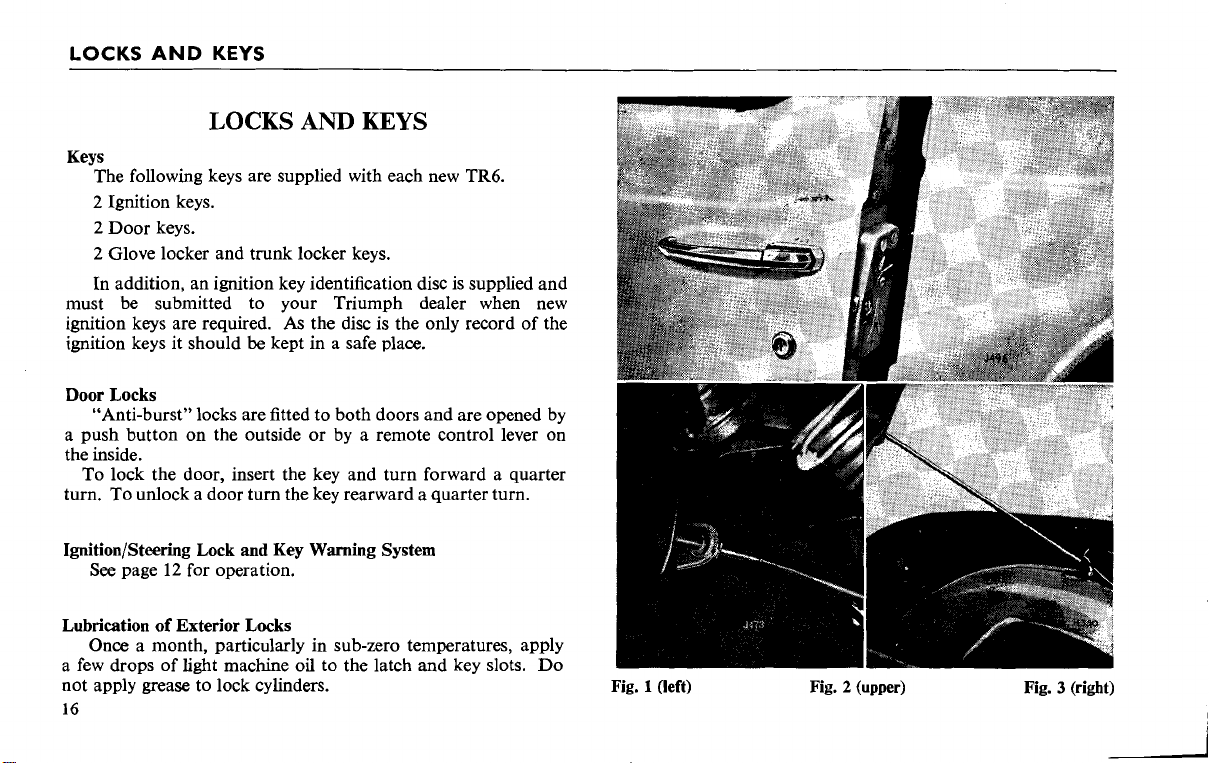
Door Locks
"Anti-burst" locks are fitted to both doors and are opened by
a push button on the outside or by a remote control lever on
the inside.
To lock the door, insert the key and turn forward a quarter
turn. To unlock a door turn the key rearward a quarter turn.
Ignition/Steering Lock
See
page
12
Lubrication of Exterior Locks
Once a month, particularly in sub-zero temperatures, apply
a few drops of light machine oil to the latch and key slots. Do
not apply grease to lock cylinders.
16
and
for operation.
AND
As
be
kept in a safe place.
Key Warning System
KEYS
the disc is the only record of the
Fig. 1
(left)
Fig. 2 (upper) Fig. 3 (right)
LOCKS
AND
KEYS
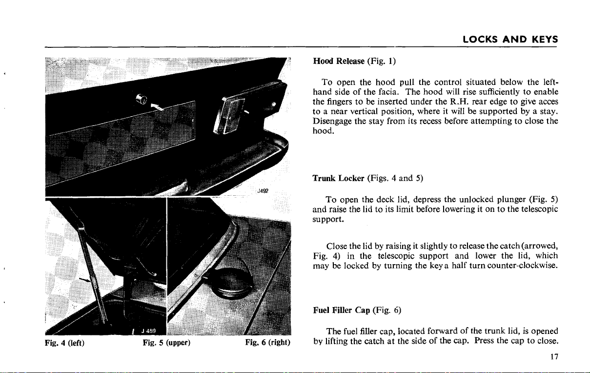
Fig. 4
(left)
Fig. 5 (upper) Fig. 6 (right)
Hood Release (Fig.
To open the hood pull the control situated below the left-
hand side of the facia. The hood will rise sufficiently to enable
the fingers to be inserted under the
to a near vertical position, where it will be supported by a stay.
Disengage the stay from its recess before attempting to close the
hood.
Trunk Locker (Figs.
To open the deck lid, depress the unlocked plunger (Fig.
and raise the lid to its limit before lowering it on to the telescopic
support.
Close the lid by raising it slightly to release the
Fig.
4)
in the telescopic support and lower the lid, which
may be locked by turning the key a half turn counter-clockwise.
Fuel Filler
by lifting the catch at the side of
Cap
The fuel filler cap, Iocated forward of the trunk lid, is opened
(Fig.
1)
R.H.
rear edge to give acces
4
and
5)
5)
catch(arrowed,
6)
the
cap. Press the cap to close.
SOFT
TOP
TOP
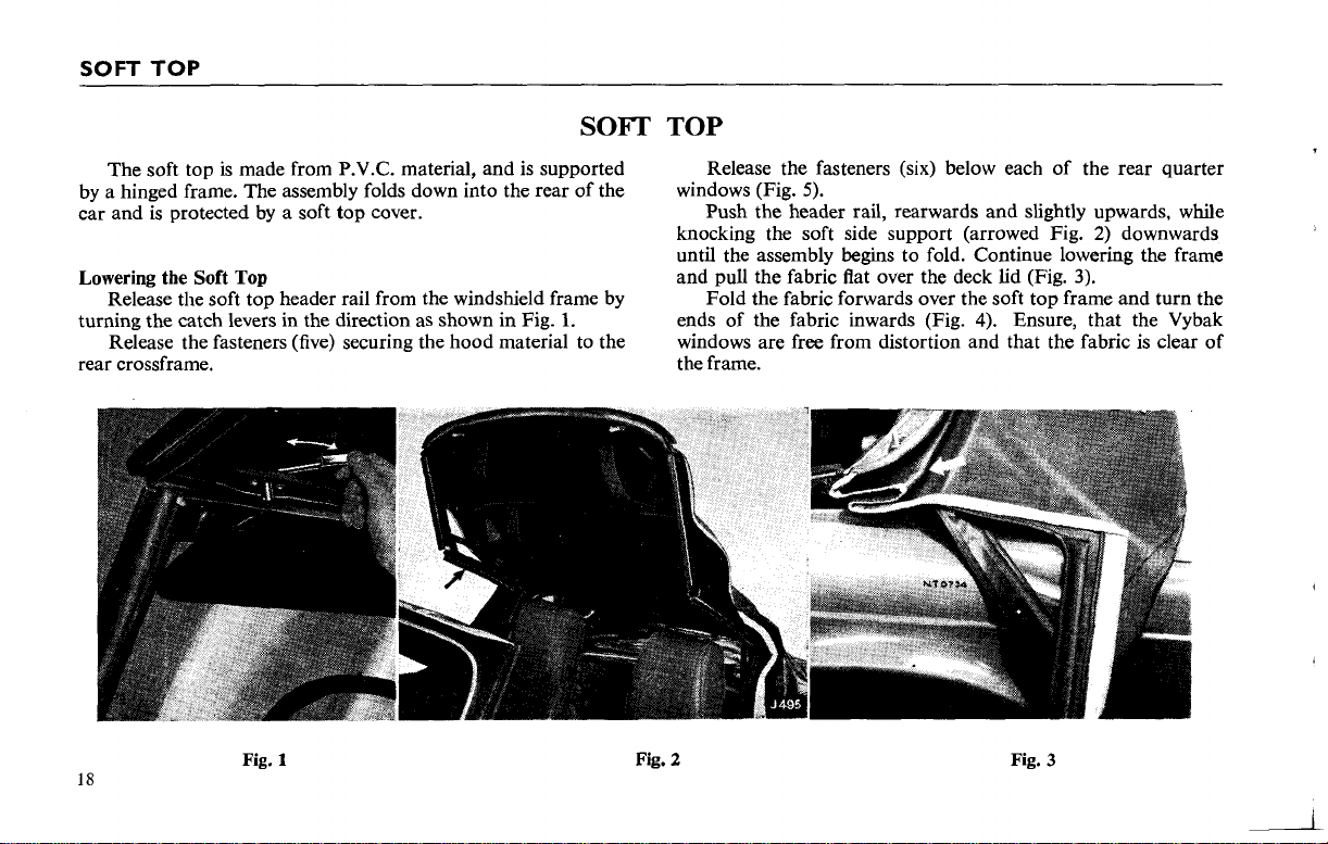
The soft top is made from P.V.C. material, and is supported
by a hinged frame. The assembly folds down into the rear of the
car and is protected by a soft top cover.
Lowering the Soft Top
Release the soft top header rail from the windshield frame by
turning the catch levers in the direction as shown in Fig.
1.
Release the fasteners (five) securing the hood material to the
rear crossframe.
18
Fig. 1
Release the fasteners (six) below each of the rear quarter
windows (Fig.
5).
Push the header rail, rearwards and slightly upwards, while
2)
knocking the soft side support (arrowed Fig.
downwards
until the assembly begins to fold. Continue lowering the frame
and pull the fabric flat over the deck lid (Fig.
3).
Fold the fabric forwards over the soft top frame and turn the
4).
ends of the fabric inwards (Fig.
Ensure, that the Vybak
windows are free from distortion and that the fabric is clear of
the frame.
Fig.
2
Fig.
3
SOFT
TOP
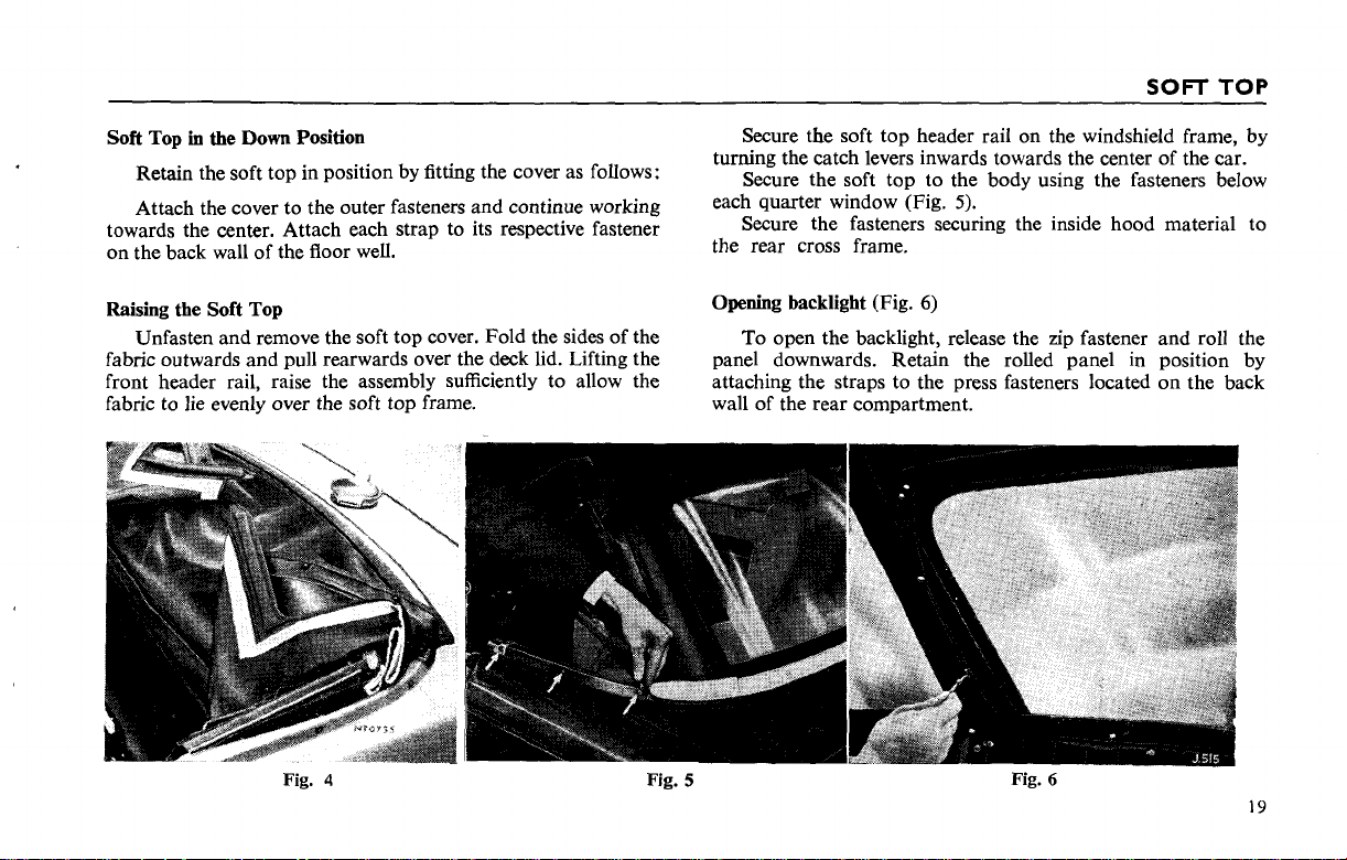
Soft Top
in
the
Down Position
Retain the soft top in position by fitting the cover as follows:
Attach the cover to the outer fasteners and continue working
towards the center. Attach each strap to its respective fastener
on the back wall of the floor well.
Raising the Soft Top
Unfasten and remove the soft top cover. Fold the sides of the
fabric outwards and pull rearwards over the deck lid. Lifting the
front header rail, raise the assembly sufficiently to allow the
fabric to lie evenly over the soft top frame.
Secure the soft top header rail on the windshield frame, by
turning the catch levers inwards towards the
center of the car.
Secure the soft top to the body using the fasteners below
each quarter window (Fig.
5).
Secure the fasteners securing the inside hood material to
the rear cross frame.
Opening backlight
(Fig.
6)
To open the backlight, release the zip fastener and roll the
panel downwards. Retain the rolled panel in position by
attaching the straps to the press fasteners located on the back
wall of the rear compartment.
Fig.
Fig.
4
Fig.
5
6
19
TONNEAU COVER-HARD
TOP
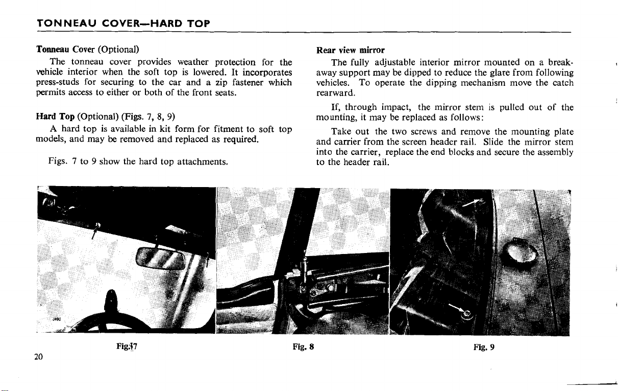
Tonneau Cover (Optional)
The tonneau cover provides weather protection for the
vehicle interior when the soft top is lowered. It incorporates
press-studs for securing to the car and a zip fastener which
permits access to either or both of the front seats.
Hard
Top (Optional) (Figs.
A
hard top is available in kit form for fitment to soft top
models, and may
be
7,
8,
9)
removed and replaced as required.
Figs. 7 to 9 show the hard top attachments.
Rear
view
mirror
The fully adjustable interior mirror mounted on a breakaway support may be dipped to reduce the glare from following
vehicles. To operate the dipping mechanism move the catch
rearward.
If, through impact, the mirror stem is pulled out of the
mounting, it may be replaced as follows:
Take out the two screws and remove the mounting plate
and carrier from the screen header rail. Slide the mirror stem
into the carrier, replace the end blocks and secure the assembly
to the header rail.
Fig.
8
Fig.
9
CARE OF BODYWORK
AND
UPHOLSTERY
CARE
Washing
Avoid using a dry cloth to wipe dust from the paintwork and
plated surfaces. Dust is an abrasive and if removed
will scratch the polished surfaces. Wash the vehicle frequently
with plenty of running water and a clean soft sponge. Soften and,
if possible, remove the mud with water before using the sponge.
When all dirt is removed, sponge off and dry with a clean damp
chamois leather. Never wash or polish the vehicle under a hot
sun.
When using an automatic car wash ensure that the radio aerial
is fully retracted.
Removing Grease and Tar
Remove grease or tar by sparing use of white spirit, but do
not apply this to rubber, particularly windshield wiper
Glass Surfaces
Glass is easily scratched. This can be avoided by always using
a damp chamois leather which is specially reserved for use on
glass only. If silicone polishes have been used on the body, take
care that the polish does not come in contact with the glass. It is
extremely difficult to remove and causes the windshield wipers to
smear.
Chromium Plating Inflammability
Frcquent washing and thorough drying is recommended,
especially during the winter months when there is likelihood of
corrosion through contamination with road salt. described above.
in
OF
this way it
bIades.
BODYWORK
Polishing
After a period of use, the formation of traffic film will cause
the paintwork to lose some of its lustre, even though the vehicle
has been carefully and
may be restored after washing by using a reputable non-abrasive
cleaner and polish.
Being the most durable, wax preparations are
where these are used regularly the old wax must first be removed
with a cleaner before further application of new wax. The frequency at which polishing is necessary will depend upon local
conditions of air pollution.
Care of Interior, Soft Top and
Brush and clean the inside of your
polish the outside of it. Use a vacuum cleaner where possible and
ensure complete removal of all dust from the interior and trim.
Wash the Upholstery (and exterior fabric) with luke-warm
non-caustic soapy water. Do not use detergents or household
cleaners
with a clean damp cloth and thoroughly dry the upholstery with
a dry duster or towel.
Wax or other polishes should not be used inside the car.
To preserve this condition do not clean interior other than as
as
these may cause damage. Remove all traces of suds
Wipe the facia and instrument panel with a damp cloth only.
The car conforms to State and Federal laws on flammability.
regularly washed. The original brilliance
preferablc, but
Tonneau Cover
car
each time you wash and
21
WHEELS
AND
TIRES
Tires
Wheels
and tires, of correct types and pressures, are an
integral part of a vehicle's design. Thus the regular maintenance
of the tires contributes not only to the safety but to the designed
functioning of the vehicle, as road holding steering and braking
are especially vulnerable to the use of incorrect
l
y pressurised,
badly fitted or worn tires.
Pressures
Adjust tire pressures in accordance with the recommendations
given below. These pressures are satisfactory for sustained
speeds up to 112 m.p.h. (180 km.h.).
Front Rear
185 SRI5 G800
185 SRI5
X
20
lblin.2 24 lbIin.2
(1.40 kg/cmz)
(1.68 kg/cmz)
NOTE: Should the vehicle be tuned to increase its maximum
be
speed, or
used for racing, consult the respective tire
company regarding the need for tires of full racing
construction.
Never bleed a warm tire but always adjust the pressure whilst
the tires are cold, i.e. before a run. As the tires
warm up their
pressures will increase.
To prolong tire life, avoid severe braking, sudden changes of
direction at speed, and driving over or against
as
this can result
in
severe damage to the tire walls. Examine the
high
kerbstones,
tires occasionally and remove flints or other road matter which
may have become embedded in the treads.
CIeoning
Wipe off any oil or grease which may
a cloth moistened in gasoline. The tires should then
be
on the tires by using
be
washed,
using only soap and water.
Tie
Wear
The characteristics of tires vary considerably and, therefore
when new tires are fitted, all four tires must be of the same type
and rating. (185-15 radial ply).
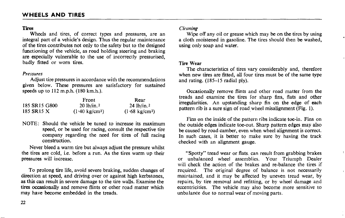
Occasionally remove flints and other road matter from the
treads and exanline the tires for sharp fins, flats and other
irregularities. An upstanding sharp fin on the edge of each
pattern rib is a sure sign of
Fins
on the inside of the pattern ribs indicate toe-in. Fins on
road,wheel misalignment (Fig. 1).
the outside edges indicate toe-out. Sharp pattern edges may also
be
caused by road camber, even when wheel alignment is correct.
In such cases, it is better to make sure by having the track
checked with an alignment gauge.
"Spotty" tread wear or flats. can result from grabbing brakes
or unbalanced wheel assemblies. Your Triumph Dealer
will check the action of the brakes and re-balance the tires if
required. The original degree of balance is not necessarily
maintained, and it may be affected by uneven tread wear, by
repairs, by tire removal and refitting, or by wheel damage and
eccentricities. The vehicle may also become more sensitive to
unbalance due to normal wear of moving parts.
1
WHEELS
AND
TIRES
Excessive wear in the center of the tread (Fig. 2) results from
over-inflation, in which condition the fabric is more easily
damaged.
Excessive wear at the outer edge of the tread (Fig.
from under-inflation, a condition which causes excessive heating
and premature tire failure.
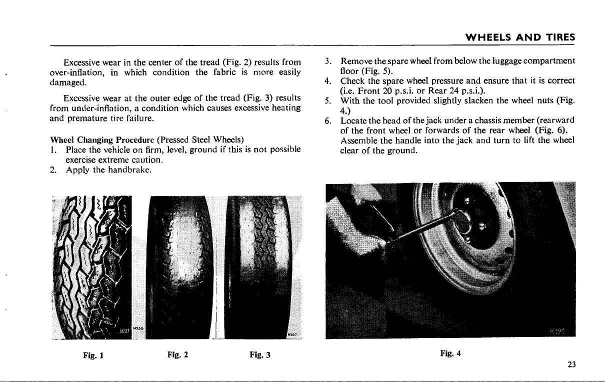
Wheel Changing Procedure
Place the vehicle on firm, level, ground if this is not possible
1.
exercise extreme caution.
2. Apply the handbrake.
(Pressed Steel Wheels)
3)
results
Remove the spare wheel from below the luggage compartment
floor (Fig.
Check the spare wheel pressure and ensure that it is correct
(i.e. Front 20 p.s.i. or Rear 24 p.s.i.).
With the tool provided slightly slacken the wheel nuts (Fig.
4.)
Locate the head of the jack under a chassis member (rearward
of the front wheel or forwards of the rear wheel (Fig.
Assemble the handle into the jack and turn to lift the wheel
clear of the ground.
5).
6).
Fig.
Fig.
1
Fig. 2 Fig.
3
4
23
 Loading...