

Triumph TR6 Handbook
THI
UMFH
Tnl
Tnl
THI
TH!UMP}I
halldbosrk
UMPH
UMPH
UMPH
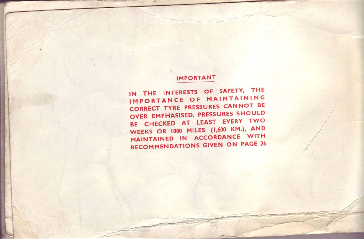
IMPORTANT
OT
N
SHO
TWO
\^/ITH
PAGE
THE
BE
LD
U
AN
D
25
THE
IN
IMPORTANCE
CORRECT
OVER
CHECKED
BE
WEEKS
MAINTAINED
INTERESTS
OF
AT
looo
IN
PRESSU
PRESSURES
LEAST
MILES
ACCORDANCE
TYRE
EMPHASISED.
OR
RECOMMENDATIONS
SAFETY'
OF
MAINTAINING
CAN
RES
EVERY
(1,600
GIVEN
KM')'
ON
/---**-<'
---
t"'
-t
,t/-^r-
TriurTlph
Handbook
Issued
TRIUMPH
MOTOR CO.
COVENTRY,
ENGLAND
by
LTD.
A
member of the
British Leyland
Motor Corporation
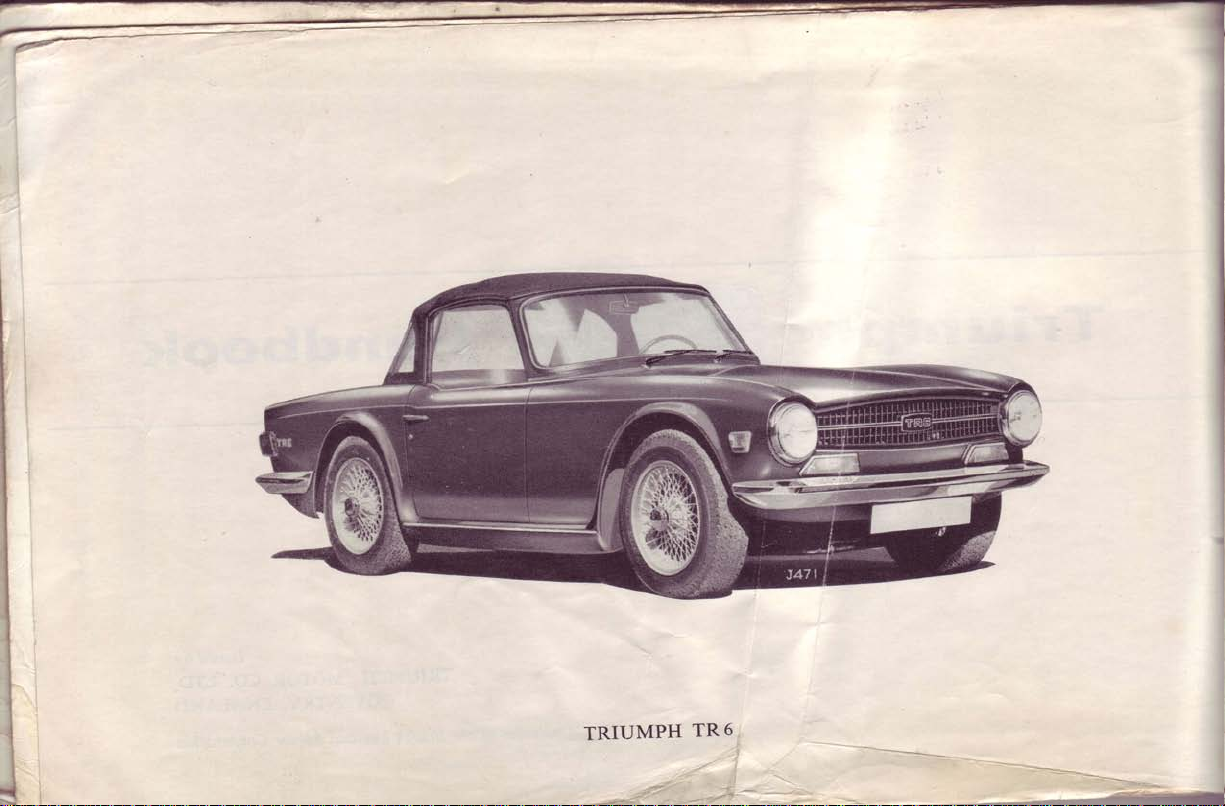
TRIUMPH
TR
6
-
Introdaction
I,
t
I
service, your
engine
will
which
of
possible
system
terms,
owners
Scheme
ll"rro*ED
incorporates
TR.6
performance,
also
TR.6
The
your
to
add
carefulty
Read
information
maintenance
Because
of
strongly
are
operated
supplied
AND
economy
embodies
confdence.
contents
the
vital
the
oJ'
complexity
the
urged
Triumph
by
the
with
system
BUrLr
a petrol
and
many
to
csr.
to
Dealers
car.
is
a long
give
to
iniection
efficiencv.
safety
new
and
This
book
sensitivity
use
and
will
of this
the proper
make
correctly
and
system
features,
which
operation,
of
the
of
desuibed
ensure
serviced
that
provides
very
the
the
in
and
care
petrol
separate
a
petrol
trained
trouble-free
consistent
which
gives,
the
Maintenance
in
the
by
high
presence
simplest
regular
iniection
Voucher
booklet
iniection
personnel.
In
all
to Service
or
the Commission
Paint and
Replacement
Dealers.
spare
Genuine
material is used and the
replacements be
descriptions
The
retaining the
up-to-date,
any alteration
Important
communications
Sparesr please
(Chassis
Trim
parts
not supplied
are
parts
marketed
are
r;il;;;;;;;;;y
r"ut"iir
Remember,
oi-ttr"-r[rooeri
units,
to
necessary.
and illustrations
basic
relating
quote
Number
Number)
Numbers
from the
under the
parts
appearing
parts
factory direct
trade
-itntiii-tJ
whiih
in this
nerein-a"iiiiGa
accessories
or
STANPART
Spare
to the
mark "stanpart"
tiii""l""i".".--
di,Lng
noica..y
do
not
book are
inO
deemed
LOCATION
Commission,
(May
be seen
Number-On
Engine
Gearbox
Rear Axle
Note:
of the
L.H.
vehicle
Parts Service
public,
general
and carry
the trade
binding.
iit"rt.ii"d
convenient
the
Yo"
-iit'sianpart"
-
for improvement
COMMISSION
OF
Paint
lifting
by
Number-On
Number-On
R.H. refers
and
from the
directed
but are
guaraltee
same
are advised,
MANUFACTURER,
The
make at
to
and
the
L.H.
R.H. side
driving
through
as
tleqefo19r
invalidate
will
time,
any
for any
or
Trim
bonnet)
side
Hypoid
to
position.
Distributors
original
the
ilsist
to
the
therefore,
without
manufacturing
AND
Numbers-On
Cylinder
of
Housing
of
Housing
Left-hand
who, in turn,
part'
The
use
on the
guarantee
if
reserves the
necessarilv
NUMBERS
TINIT
Scuttle
Block
Flange
Right-hand
and
supply their
high
same
parts
these
^of
fitted to
vour
right - whilst
bringing
or commercial
Panel
quality
should
vehicle.
this book
reason'
side
,;--
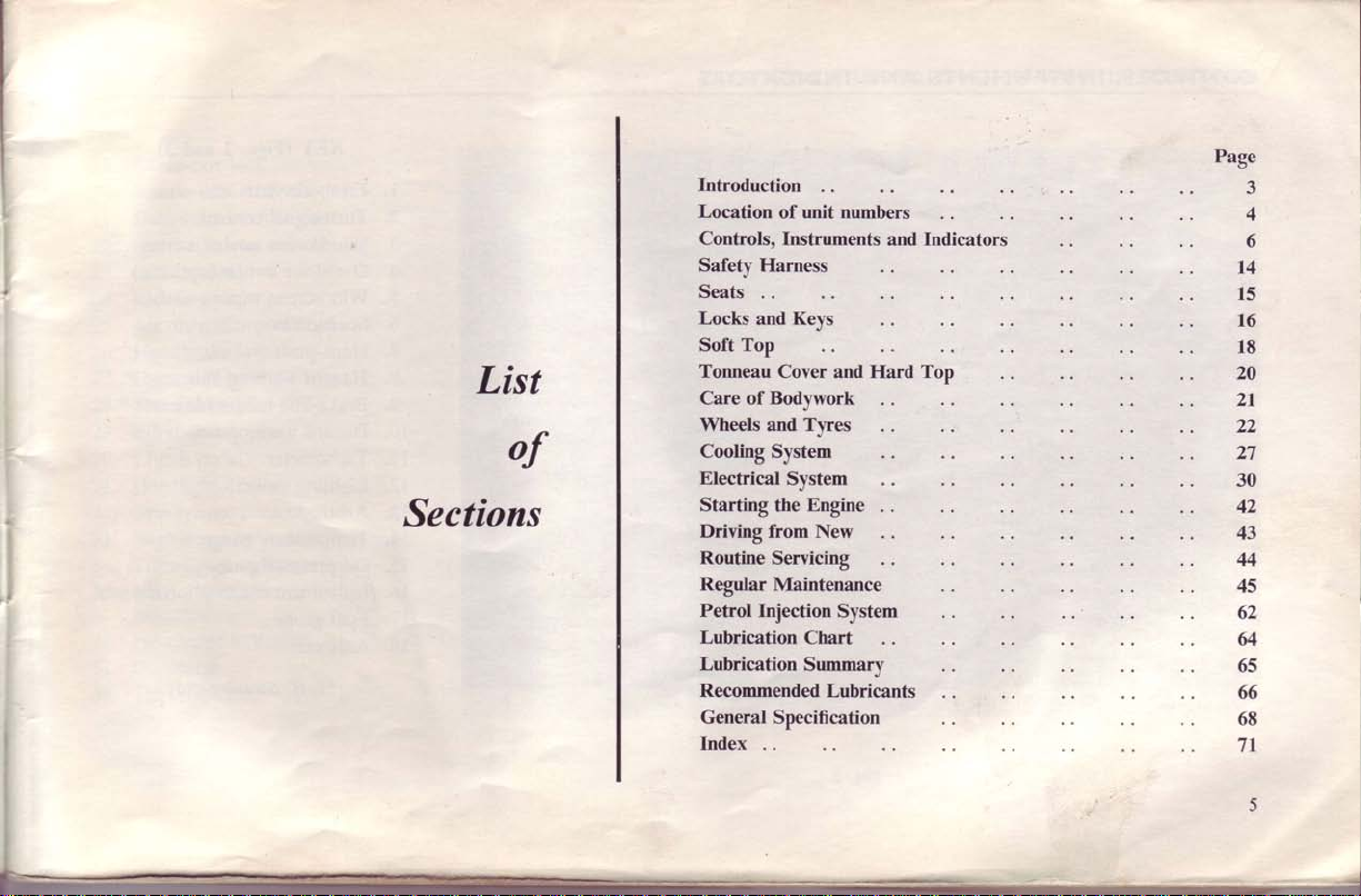
List
of
Sections
Introduction
Location
Controls,
Safety Harness
Seats
Locks
Soft Top
Tonneau
Care of Bodywork
Wheels and
Cooling
Electrical
Starting the
Driving
Routine
Regular Maintenance
Petrol Injection
Lubrication
Lubrication
Recommended
General Specification
Index
of unit numbers
Instruments
and Keys
Cover and Hard Top
Tyres
System
System
Engine
from
New
Servicing
System
Chart
Summaly
Lubricants
and Indicators
Page
3
4
6
t4
15
t6
18
20
21
22
27
30
42
43
44
45
62
g
65
66
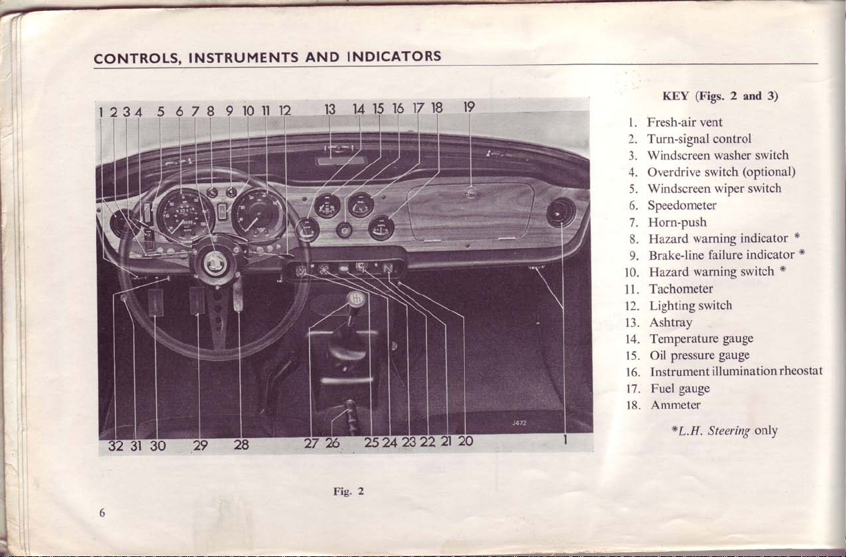
CONTROLS,
INSTRUMENTS
AND
10,...11
'
t
li
t'
INDICATORS
(Figs.
KEY
1. Fresh-air
Turn-signal control
2.
Windscreen washer
3.
4. Overdrive
Windscreen
5.
Speedometer
6.
Horn-push
7.
8. Hazard
Brake-line
9.
Hazard
10.
Tachometer
11.
Lighting switch
12.
Ashtray
13.
Temperature
14.
Oil pressure
15.
Instrument
16.
Fuel gauge
17.
Ammeter
18.
vent
switch
warning
warning
*L.H.
2
and 3)
switch
(optional)
wiper switch
indicator
indicator
failure
switch
gauge
gauge
illumination
Steering
onlY
*
*
x
rheostat
Fig.
2
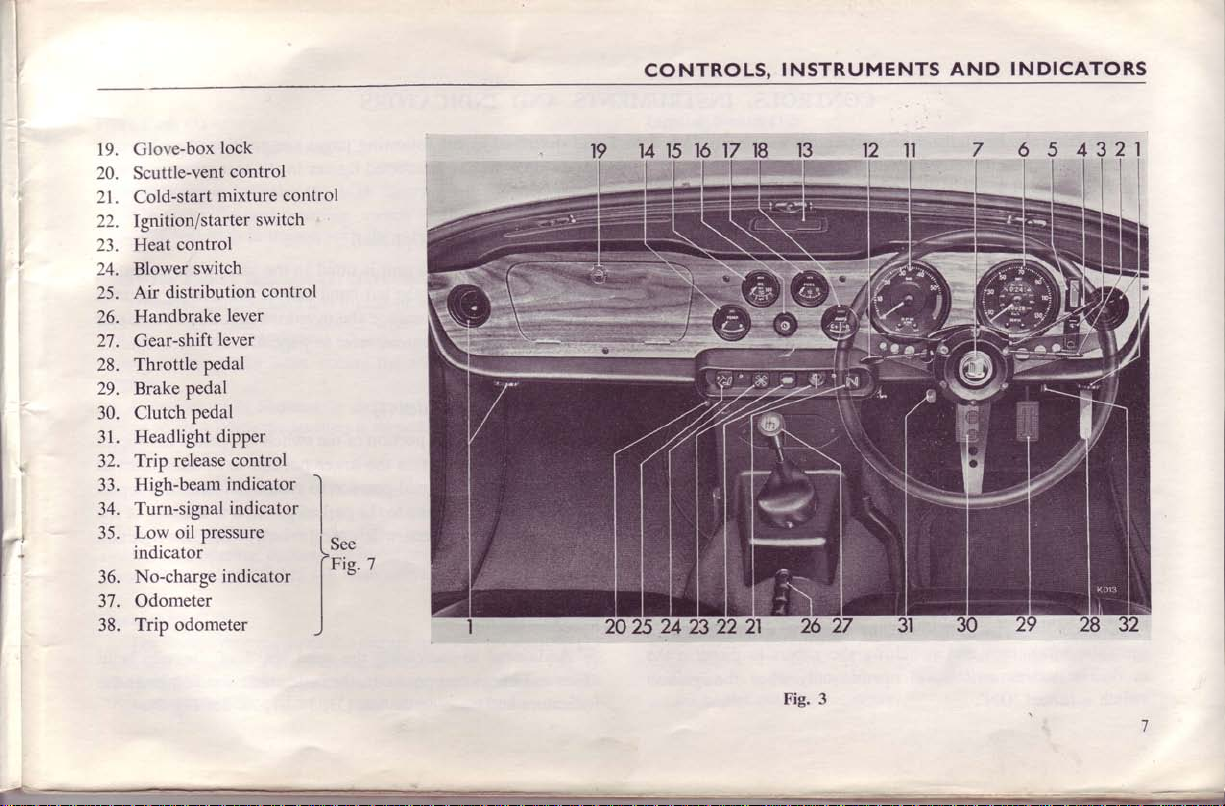
CONTROLS,
INSTRUMENTS
AND
INDICATORS
-:
Glove-box
19.
'
'
,
20. Scuttle-vent
21. Cold-start
Ignition/starter
22.
23. Heat
Blower
24.
Air
25.
Handbrake
26.
27. Gear-shift
28. Throttle
29. Brake
30. Clutch
31. Headlight
Trip
32.
High-beam
33.
Turn-signal
34.
lock
control
mixture
control
switch
distribution
lever
lever
Pedal
pedal
pedal
dipper
release control
indicator
indicator
control
switch
control
I
I
35'
ffiluo,'jf"ressure
No-charge
36.
37. Odometer
Trip odometer
38.
indicator
tl:" -
t'tg'
I
I
)
/
n
3
Fig.
1
T
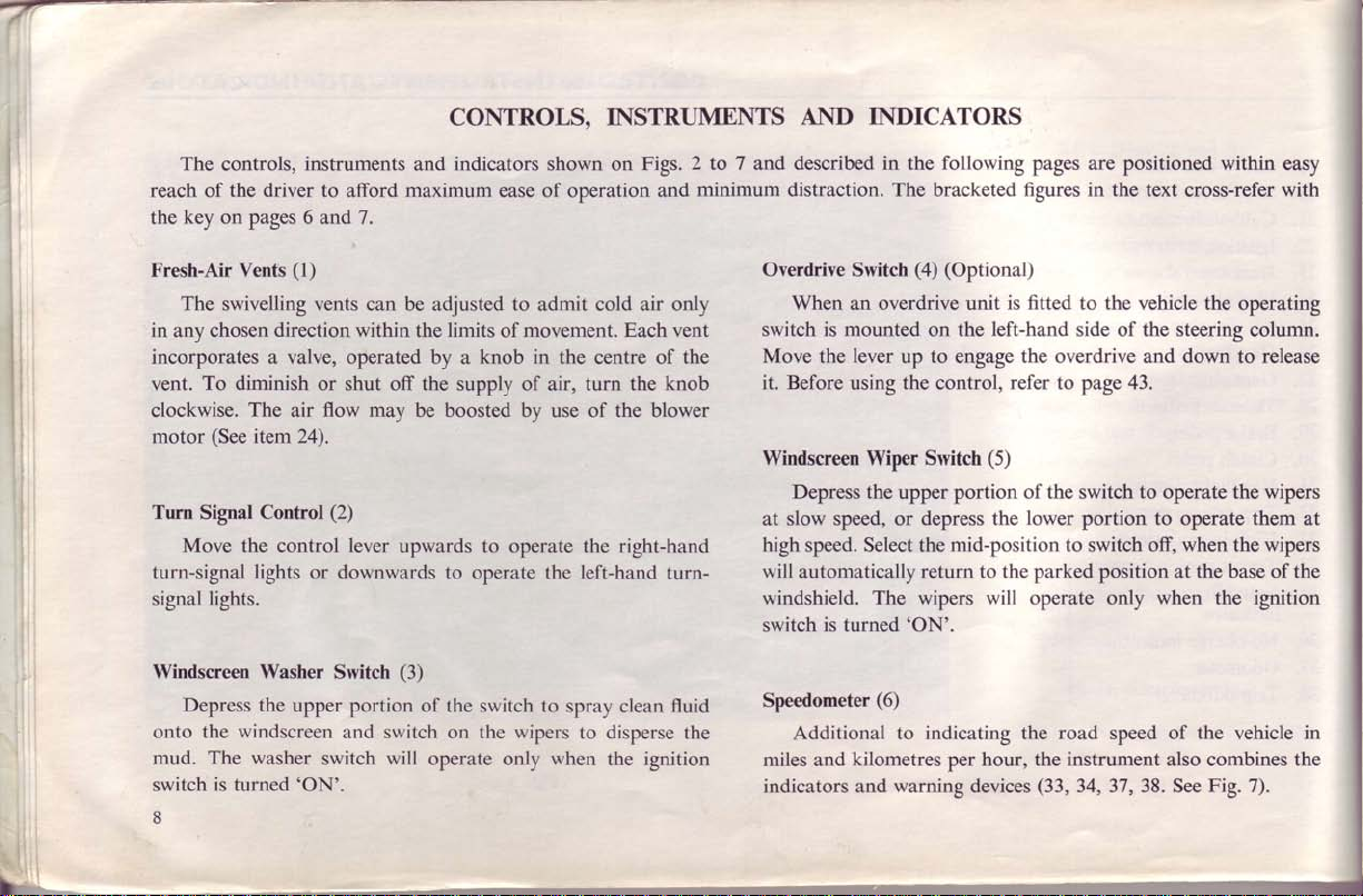
CONTROLSO
The
controls,
reach
the
the driver to
of
key on pages 6
Fresh-Air Vents
The swivelling vents can be
in
any chosen
incorporates a valve, operated by a knob in
To diminish
vent.
clockwise.
(See
motor
Turn
Signal
Move the control lever
turn-signal
lights.
signal
Windscreen Washer
Depress the
the windscreen
onto
mud. The washer
is
switch
8
turned'ON'.
instruments
afford
and7.
(1)
direction within
or shut off the supply of air, turn the
The
item 24).
lights
flow may
air
Control
(2)
or downwards to
Switch
upper portion of the
and switch
switch will
indicators
and
maximum
adjusted
the
be boosted by
upwards
ease
to
limits
movement. Each
of
to operate the right-hand
operate
(3)
switch to spray
the
on
wipers to disperse
operate only when
INSTRUMENTS
shown on
of
operation
admit cold
the centre
of the blower
use
left-hand
the
the
Figs.
air only
clean
ignition
2
and
vent
of the
knob
turn-
fluid
the
AND
to 7 and
minimum
described in the
distraction. The bracketed figures in the
Overdrive Switch
When
switch is mounted
Move
it. Before
Windscreen Wiper Switch
Depress
at slow
high speed. Select
will automatically return to
windshield. The wipers will operate only when the
switch is turned'ON'.
Speedometer
Additional to
miles and
indicators and
INDICATORS
overdrive
an
lever
the
speed,
up to engage the overdrive and down to release
the
using
the
upper portion
or
(6)
kilometres
warning
following
(4) (Optional)
on the
control,
depress the
mid-position
the
indicating
per hour, the instrument also combines the
pages are positioned within
fitted
is
unit
left-hand
refer to
(5)
the
devices
to the
side
page
of the switch
lower
portion to operate them at
to switch off,
parked position at
road
the
(33,
34, 37, 38.
easy
text cross-refer with
the
vehicle
of the steering column.
43.
to
operate the wipers
of
speed
operating
when
the wipers
the base
the vehicle in
Fig. 7).
See
of the
ignition
(7)
Push
Horn
to
Press
Haizard Warning
When
indicator
Brake-line
When
and
extinguished
fronC or
brightly.
A
failing to glow
englne.
Hazard
If the vehicle
vehicles,
system".
when all
Tachometer
The
minute and
The speed
"Recommended
operate
the
flash
will
Failure
ignition switch
the
oil pressure"
"low
when the
rear
broken
bulb
when
Warning
warning
To operate,
turn-signal
(ll)
tachometer
combines
range within the coloured
horns.
the
(L.H.
Indicator
'hazard
Indicator
brake
Switch
is immobilised and
may be
Speed Limits"
(8)
warning
in
filament
the ignition
lights will
indicates the
with the exterior
unison
(9) (L.H.
is
turned
indicator
is running.
engine
lines occur, the
is indicated
(10) (L.H.
given
depress the
two warning
flash intermittently.
Steering
switch'
is turned
by
lower
engine speed
mentioned
(10)
Steering
on the
lights glow
Should
indicator
by the
on, before
Steering
constitutes
the
using
Portion
indicators
segments
on page
only)
is operated
warning
"brake
only)
in revolutions
(35,
lights.
only)
line failure"
faintly
ahazard
"hazard warning
of
is subject
and
failure
(9)
will glow
warning
starting
to other
the switch
See
36,
43.
the
are
the
of
light
the
(10)
Per
Fig. 7).
the
to
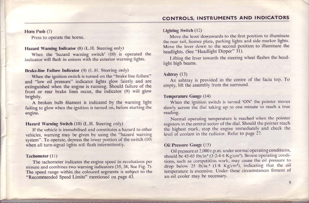
CONTROLS,
(12)
Lighting
the
Move
headlights.
light
Ashtray
empty,
Temperature
slowly
reading.
registers
thE
level oT
Oil
should
tions,
drop
temperature
an
Switch
lever
the
Move
rear
Lifting
high beams.
An ashtray
When
Normal
highest
Pressure
Oil
oil
licence plate,
tail,
lever
the
(See
lever towards
the
(13)
assembly
lift the
Gauge
ignition
the
the
across
operating
central
in the
mark,
coolant
Gauge
pressure
be 45-65lbs/in'?
competition
as
such
25
below
is excessive.
may be
cooler
at
INSTRUMENTS
downwards
to
down
"Headlight
is
provided
(14)
switch
taking
dial
temperature
scctor
stop
radiator.
in the
(15)
2,000
tUlin.'
necessary.
to the
parking
the second
from
the
r.p.m.
1l'Z-+'6
1t'S
Undci
lights and
Dipper"
the steering
in the centre
the surround.
is turned
to
up
the dial.
of
engine-immediately_and
Refer
under
Kg/cm').
may cause
work,
Kg/cm),
these
AND
first
position
side
position
31).
wheel
the
of
'ON'
the pointer
minute
one
reached
is
Should.the
to page
operating
normal
Severe
the
indicating
circumstances
INDICATORS
to illuminate
marker
illuminate the
to
flashes
to
when
27.
operating
oil pressure
lights.
head-
the
facia top.
moves
reach a
the pointe-r
pointer
reach
check
conditions,
condi-
the
that
fitment
To
true
the
to
oil
of
9
CONTROLS,
INSTRUMENTS
AND
INDICATORS
I
l
l
:
Instrument
Further
operates
Fuel
fuel
moves
steady
ment,
Ammeter
The ammeter indicates
The
left-hand
Glove Box
Th9
turn
Scuttle
Fresh
scuttle
wards
closed, the heater
10
Illumination
Turn
the knob
rotation
only when
(17)
Gauge
The fuel
tank. When
charging rate
clockwise and
gauge indicates
slowly
across
reading
until the ignition
ventilator.
and closed
which
(18)
side of
Lock
g]ov9-box may
Vent Control
is
air
'Zero'and
(19)
admitted
Rheostat
clockwise
of
the knob diminishes
the lighting
the
ignition
the dial
it will
is
is indicated
be
opened
(20)
This
is
by
pushing it
unit
recirculates
(16)
to illuminate
switch
the
switch is
taking
maintain
switched'OFF'.
the
rate
when
discharge,
unlocked
by
depressing
to the
heater
opened
forwards.
the light
is'ON'.
approximate
turned
up to
one minute
regardless
of battery
by
by
air already
charge
the
pointei
by movement
turning
the-locking
duct
pulling the lcver
when
the
contents
'ON'
of
vehicle move-
or discharge.
moves
the key
through
the
in
the
instruments.
intensity
of the
the
pointer
to ieach
to
a
quarter
bariel.
the
(20)
the
right.
open
rear-
to the
ventilator is
vehicle.
Cold Start Mixture
-
from
and
use
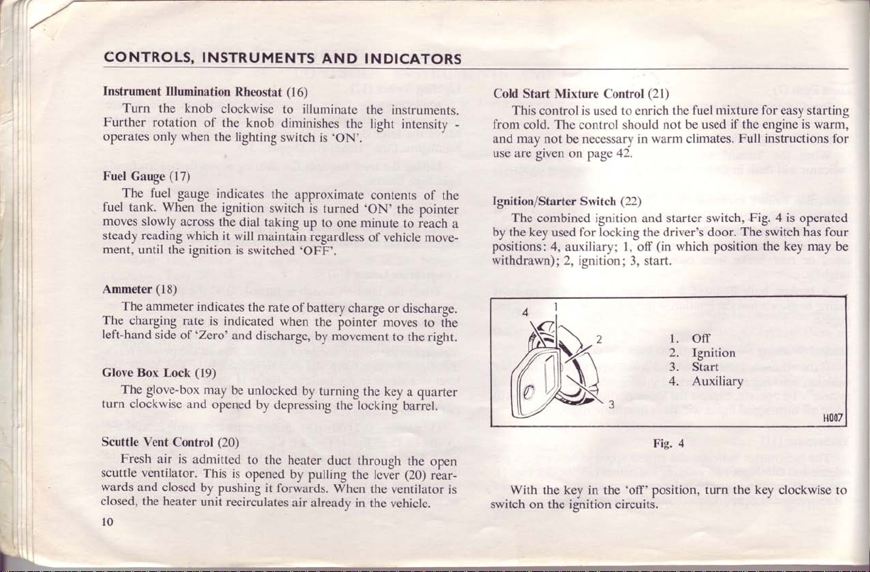
Ignition/Starter
a
by
positions: 4,
withdrawn); 2,
switch
Control
This
cold. The
may not
are given on
The
combined ignition and starter switch,
key
the
is
control
used to enrich
control
be
necessary
page
Switch
for locking the driver's door.
used
auxiliary;
ignition; 3,
(21)
the
not be used
should
in warm climates.
42.
(22)
(in
l,
off
start.
which position
l. off
2.
3. Start
4. Auxiliary
Fig. 4
With
the key in the
the ignition
on
'off'position,
circuits.
fuel mixture
if the
Full instructions for
Fig. 4 is
The switch has four
Ignition
turn the
for
easy
is
engine
operated
the key may
kev
clockwise to
starting
warm,
be
H007
Turning
permits
ignition
Heat Control
The
flow
of
intermediate
any
when the control
the control
Blower
The blower
of air
to operate
position
when the
the key
the use of a
is
switched
(23)
heat control operates a water valve which
water through
is
pulled out.
(24)
Switch
motor,
through
the heater
the blower motor
for high speed operation. The blower will operate only
ignition switch
anti-clockwise to
radio when
off.
the
position
is
pushed in; maximum heat is
operated by a switch
the vehicle
heater
unit.
required. The water
as
Pull
unit.
at slow speed or
is
turned
the
The
the switch to
'ON'.
auxiliary
is
stationary
control
available
(24)
boosts the
its first
position
the
and
regulates the
may
be set at
is
valve
closed
when
flow
position
to its second
CONTROLS,
is distributed
air
out,
'flap'
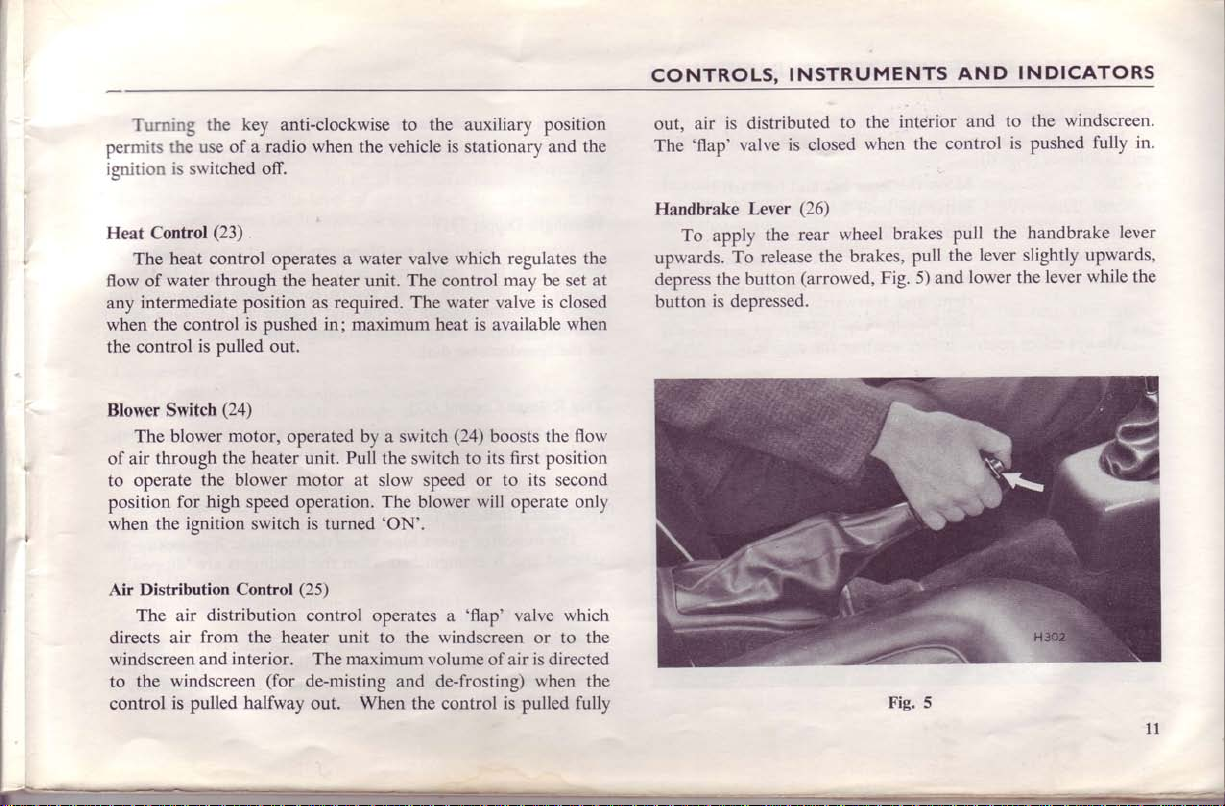
To
valve
Lever
the
apply
release
To
button
the
is
depressed.
The
Handbrake
upwards.
depress
button
INSTRUMENTS
interior
the
to
the control
wheel
the
when
brakes
brakes,
Fig. 5) and
pull
pull
the
is closed
(26)
rear
(arrowed,
AND
to the
and
the
lever
lower the
INDICATORS
windscreen'
lever
fully in.
lever
upwards,
while the
is
pushed
handbrake
slightly
Air Distribution
distribution
air
The
from the heater
directs
windscreen
to
control
air
windscreen
the
is
and
pulled
Control
interior.
(for
halfway
(25)
control operates
to
unit
The maximum
de-misting
out. When the control is pulled
the windscreen or to the
and de-frosting)
'flap'
a
volume of air
valve which
is
when the
directed
fully
Fig. 5
ll
CONTROLS,
INSTRUMENTS
AND INDTCATORS
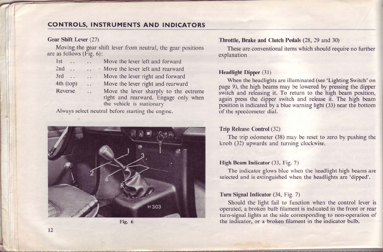
Gear
Shift
Moving,the
follows
are as
lst
2nd
3rd
4th
Reverse
Always
Lever
(Fig.
(top)
select neutral
(27)
gear
shift
6):
lever
from
Move
the lever left
Move
the lever left
Move
the lever
Move
Move
right
lever
the
the lever
rearward.
and
the vehicle is
before
starting
neutral,
the gear positions
forward
and
rearward
and
right
and
right
and rearward
sharply to the
Engage
stationary
the engine.
forward
only when
extreme
Throttle,
Brake
These
are conventional
and Clutch Pedals
items which
explanation
Headlight
When
page
the high
9),
switch and releasing it. To
again press the dipper
position is indicated
(31)
Dipper
the headlights
beams
by a blue
illuminated
are
may be lowered
return
and release it. The high
switch
warning
of the speedometer dial.
Trip Release
Control
The trip odometer
(32)
knob
upwards and turning clockwise.
High Beam Indicator
The indicator
selected
Turn
is
and
Signal Indicator
Should the
operated, a broken bulb filament
turn-signal
lights
(32)
(38)
may be reset to zero by
(33,
Fig.
glows blue
extinguished
(34,
Fig. 7)
light fail
at
the
to
side
7)
when the headlight high beams
when the headlights
function when the
is indicated in the front
corresponding to
the indicator, or a broken filament
(28,29
and
should
30)
require
(see'Lighting
by pressing the dipper
to the high beam
(33)
light
near
are
control
non-operation
in
indicator bulb.
the
no further
Switch'
position,
beam
the bottom
pushing
'dipped'.
lever
rear
or
on
the
are
is
of
CONTROLS,
INSTRUMENTS
INDICATORS
AND
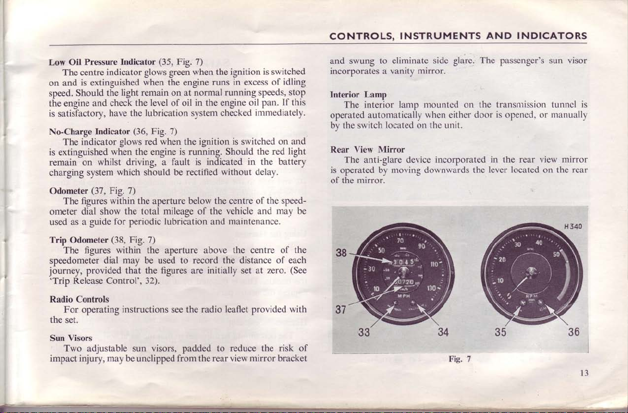
Low
The centre
on
and
speed. Should
the engine
is satisfactory,
No-Charge
indicator
is extinguished
the
check
and
have the
Indicator
Pressure
Oil
The indicator
is extinguished
remain
charging
Odometer
The
when the engine
whilst driving, a
on
system
(37,
Fig.
within the
figures
ometer dial show
used as
a guide
Trip Odometer
The
speedometer
journey,
'Trip
Release Control',
Controls
Radio
for
(38,
figures within the aperture above
dial may be
provided that the
For operating
the
set.
Visors
Sun
Two
adjustable
injury, may be
impact
Indicator
(35,
Fig. 7)
glows green
when
light remain
the level
the engine
on at
oil in the engine
of
lubrication
(36,
Fig.
7)
red when
glows
the
is
fault is indicated
which
should
be rectified
7)
aperture
the total
periodic
mileage
lubrication
Fig. 7)
to record the distance
used
figures
32).
instructions
see the
sun visors, padded to
unclipped
from the
the ignition
when
runs in excess
running speeds,
normal
oil pan.
checked
svstem
ignition
running.
is
switched
Should the
in the battery
without delay.
below the centre
the vehicle and
of
maintenance.
and
the centre of the
initially set at
are
leaflet
radio
reduce the risk of
rear
mirror bracket
view
is switched
idling
of
stop
If
this
in-rmediately.
on and
light
red
of the speed-
may be
of
each
(See
zero.
provided with
Lamp
interior
mirror.
to eliminate
a vanity
lamp mounted on the
located
moving
and swung
incorporates
Interior
The
operated automatically
by
the switch
Rear View Mirror
The anti-glare device
is operated by
of the
side glare.
mirror.
when either
on the unit.
incorporated
downwards
Fig. 7
The
passenger's
transmission tunncl
is
door
the
opened, or
in the rear
lever located
sun
rnanually
mirror
view
on the
visor
is
rear
l3
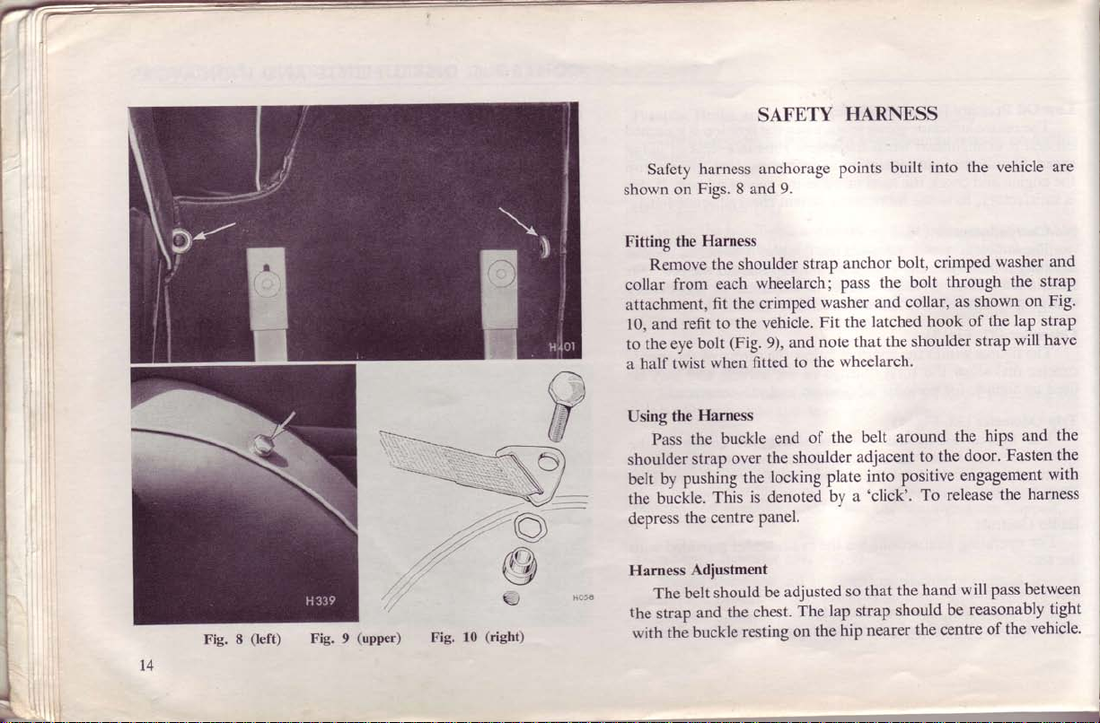
Safety
shown
SAFETY
harness anchorage
Figs. 8 and
on
HARNESS
into the vehicle
built
points
9.
':,j
t4
Fie.
8
(left)
Fig. 9
(upper)
Fig.
10
A
6)
(right)
Fitting the
Remove
from
collar
attachment,
refit
and
10,
eye
to the
twist
half
a
the
Using
the
Pass
shoulder
belt
the
depress
Harness
the
with
strap
by pushing
buckle.
the
Adiustment
belt
The
strap
buckle
thi
Harness
shoulder
the
wheelarchi
each
fit the crimped
the vehicle.
to
(Fig.
bolt
when
9),
fitted
Harness
buckle
the
over
the
denoted
is
This
panel.
centre
be adjusted
should
the chest.
and
resting
strap
and
to the
end
shoulder
locking
The
on
pass
washer
Fit the
note
wheelarch.
of the
plate
by a
lap strap
hip
the
anchor
the bolt
and
latched hook
the shoulder
that
belt around
adjacent
into positive
'click'.
that
so
should
nearer
crimped
bolt,
collar,
to
To
hand
the
the centre
through
shown
as
the
of
strap
hips
the
door.
the
engagement
release
will
reasonably
be
of
washer
the
on
lap strap
will
and
Fasten
the
between
pass
the
and
strap
Fig.
have
the
the
with
harness
tight
vehicle.
SAFETY
HARNESS
AND
SEATS
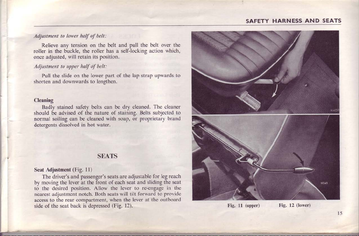
Adjustment
Relieve any
to lower
tension on the
roller in the buckle,
retain its
once
adjusted,
Adjustment
Pull the slide
shorten
will
to upper half
downwards to
and
on the lower part of
Cleaning
Badlv stained
should
6e
normal soiling
detergents
Adjustment
Seat
The driver's
by moving
to the desired
nearest
access
side
adjustment
to the
of the seat
safetv belts can
advised
of tire nature of stairiing.
can
dissolved
(Fig.
and passenger's seats
lever
the
position.
rear compartment,
back is
half of belt:
the roller
position.
of
belt:
lengthen.
be
cleaned
in hot water.
SEATS
11)
front of each
at the
Allow the
Both
notch.
depressed
belt and pull
has
a selfJocking
the
drv
be
with soap,
are adjustable
seat and sliding
lever
tilt
will
seats
when the
(Fig.
12).
the
belt over the
which,
action
lap
strap upwards
The
cleaned.
Belts
cleaner
subjected
or proprietary
leg
for
the seat
re-engage
to
forward to provide
lever
at the
outboard
to
brand
reach
in the
Fig.
11
(upper)
Fig. 12
(lower)
l5
ffi
vehicle
The
obtained
being
operite
trunk
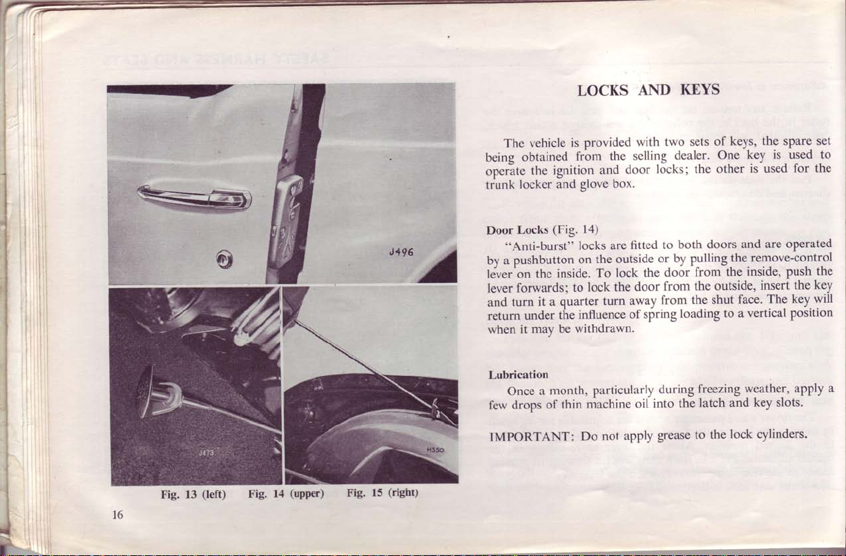
Door
"Anti-burst"
by a pushbutton
lever^on
lever
turn
and
return
when
ignition
the
and
lockcr
(Fig.
Locks
inside.
thc
forwards;
it a quarter
under
may
it
the
be
LOCKS
is provided
the
frbm
and
box.
glove
1a)
locks are
the outside
on
lock the
To
lock the
to
turn
influence
withdrawn.
AND
with
selling
locks; the
door
fitted
or_ by pulling
door
away
of spring
I(EYS
two sets
dealer.
both
to
from the
door
from the
from the
loading
of
Orre
other
doors
the.remove-control
outside,
shut
to a
is used to
key
is used
and are
inside, push
insert
The key.
face.
vertical
the spare set
keys,
for the
operated
the
key
the
will
position
I
r
l6
Fig.
13
(left)
Fig.
14
(upper)
Fig.
15
(right)
Lubrication
month,
a
Once
few drops
IMPORTANT:
of
thin
Do
particularly
niachine
apply
not
into the
oil
during
grease
freezing
latch and
lock cylinders'
to the
weather, apply
key slots.
a
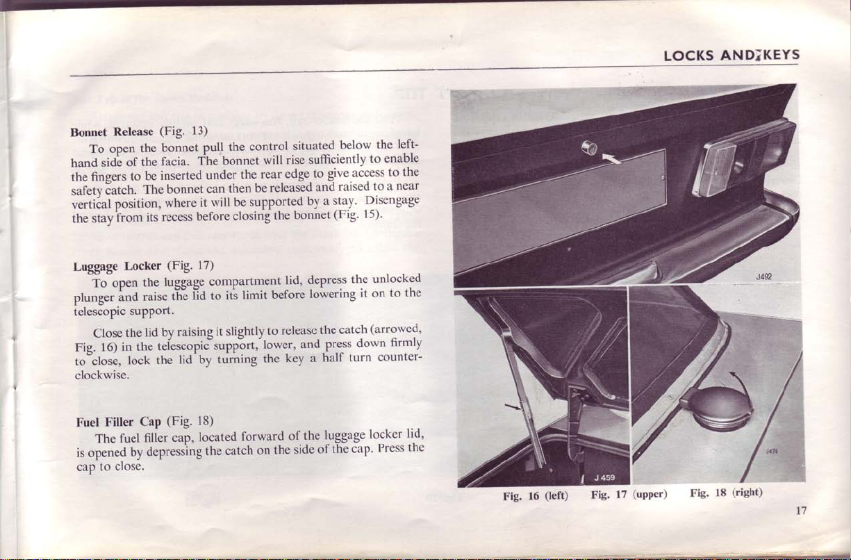
Bonnet
hand
G
Release
open
To
of
sidf
to
fing.tr
Eatch.
safety
vertiial
the stayirom
position,
to
Close
16)
Filler
The
to
Locker
op.t
ind
the
in
fuel
close.
Luggage
plunger
telescopic
Fie.
to"close,
clockwise.
Fuel
is opened
cap
support.
lock
by
(Fig.
13)
the control
pull
bonnet
the
the
be
The
its
the
raise
lid by
the
the
Cap
filler
depressing
The
facia.
inserted
recess
tefescopic"supp-ort,-lower,
bonnet
it will
where
before
(Fig.
17)
luggage
t'10 to
tTi"
raising
lid'by
(Fig.
18)
located
cap,
under
can
compartment
it slightly
turning
the catch
will
bonnet
rear-
the
released
be
then
be supported
the
closing
before
limit
iti
to
the
forward
the
on
situated
sufficiently
rise
edge.to
and
by
bonnet
depress
lid,
lowering
release
and
a
key
the
of.
side
below
to
give.access
raised
Disengage
u
9!r.y'
(Fig'
15)'
the
it on
(arrowed,
catch
the
down
press
turn
half
the
locker
cap.
luggage
of
left-
the
enable
the
to
near
a
to
unlocked
to the
firmly
counter-
lid,
the
Press
Fie.
16
(left)
Fig.
ir+i,iffi
(upper)
t7
LOCKS
Fig.
AND;KEYS
(right)
18
t7
7-
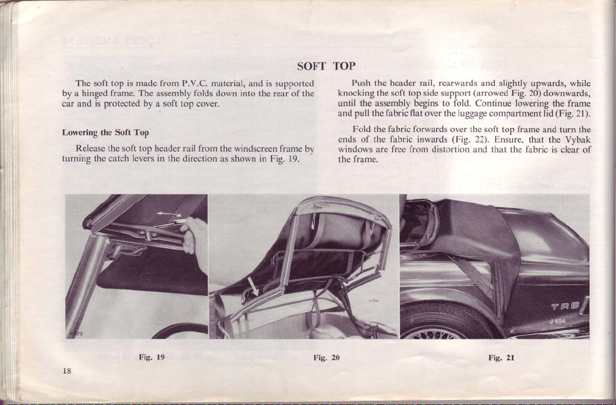
The
by a
car and
top is made from P.V.C. material,
soft
hinged frame. The
is
protected
by
Lowering the Soft Top
Release the soft top header
turning the catch
18
levers
Fig. 19
assembly folds down into
and
a soft top cover.
in the
rail from the
direction as
windscreen frame
shown
SOFT
is
supported
the rear of the
in Fig.
by
19.
TOP
Push the header rail, rearwards
knocking
until the assembly begins to fold. Continue lowering
and pull
ends
windows
the
Fig. 20
the soft top side support
the fabric flat
Fold the fabric forwards
frame.
of the
are
fabric inwards
free from
over the
distortion and that the fabric
and slightly
(arrowed
luggage
over the soft top frame
(Fig.
compartment
22). Ensure,
Fig.
Fig.
21
upwards,
20)
downwards,
the
lid
and
that
the Vybak
is
while
frame
(Fig.
turn the
clear of
21).
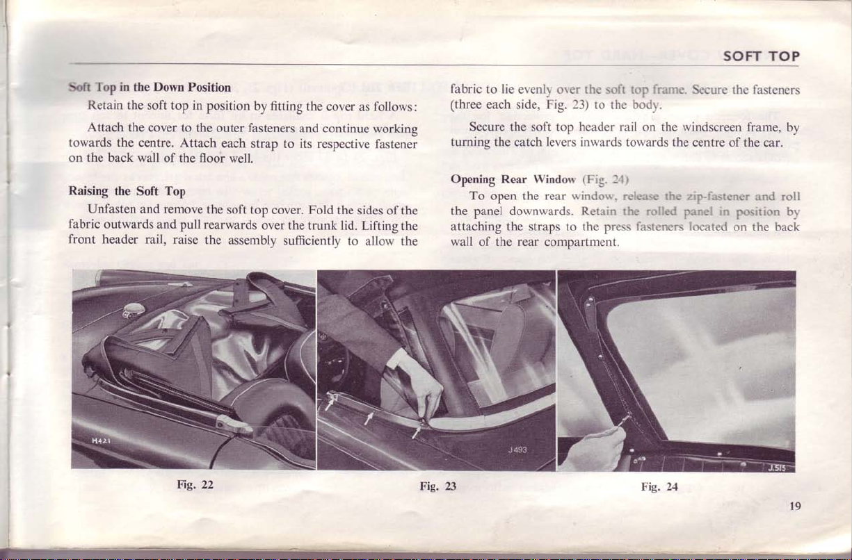
Retain
Attach
in
the
the soft top
the cover
centre. Attach
Soft Top
towards the
on the back wall
Raising
fabric
front
the Soft
Unfasten
outwards and
header rail,
and
Down
Position
in
to the
of
floor
the
Top
remove
pull rearwards
raise
position
by fitting
outer fasteners
each strap
well.
the
soft top
over
the
assemblv
the
cover
and continue
to its respective
cover. Fold
the
the trunk lid.
sufficientlv
to
follows:
as
working
fastenei
sides of the
Lifting
the
allow the
fabric
to lie
evenlr orer the soft top franrc-.
(three
each side, Fig. 23)
Secure the
turning the
Opening Rear
To
the
attaching the
wall
catch
open the rear
downwards. Retain the rolled
panel
of the rear
to the
soft top
Windon'
straps to the press
header rail
levers
inwards
(Fie.
lrindos.
compartment.
l-ll
rc'lease the ziplastener
SOFT TOP
Secure the fasteners
bod1.
on the winciscreen frame,
towards the
ibsteners located
centre of the
in
panel
position
on the back
by
car.
and roll
br'
Fig.
22
Fig. 23
Fig.
24
t9
7-
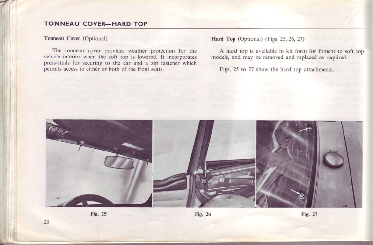
TONNEAU
Tonneau
vehicle
press-studs
permits
The
Cover
tonneau
interior
for
access to
COVER-HARD
(Optional)
cover
when the
securing
either
or both
provides
soft top is lowered. It incorporates
to the
weather protection for
car
of the
TOP
and a
front
zip fastener
seats.
the
which
Hard
Top
A hard top is
models,
and
Figs. 25
(Optional)
available
may
be removed
27
to
shon' the hard
(Figs.
25,26,27)
in kit
form for
and
top
replaced
attachments.
fitment
required.
as
to soft
top
,
ll
:l
CARE OF
BODYWORK
Washing
Avoid using a dry cloth
of running
remove
is removed,
leather.
Dust is
an abrasive and
surfaces. Wash the vehicle
water
the mud with water
sponge off and dry with
Never
wash or
plated surfaces.
will
scratch the polished
with
plenty
if
possible,
When
all dirt
chamois
sun.
Removing Grease
Remove
not
apply
Glass
Surfaces
is
Glass
damp
a
chamois
glass only.
and Tar
or tar
grease
this to rubber,
easily scratched.
leather
If
silicone polishes
by
particularly
which is
care that the polish does not
smear.
difficult to
remove
extremely
to
Chromium Plating
Frequent washing
especially
corrosion
during the
through
and thorough
winter months
contamination with road
to wipe dust
from
the paintwork and
if removed in this way it
frequently
and a clean soft sponge.
Soften
before using the sponge.
a clean
the
polish
vehicle under a
sparing use of white spirit, but do
windscreen
This
can be avoided by always using
specially reserved
have been
come in
used on the
contact with the
wiper blades.
for
use on
body,
glass.
and causes the windscreen wipers
drying
when there is
is
recommended,
likelihood
salt.
and,
damp
hot
take
It is
of
Polishing
After
the
has
may
cleaner
where these
with
quency
conditions of air
Care
polish the outside
ensure
non-caustic
cleaners as these may
with a clean damp
a
Wax or other polishes should not
a period of use, the
paintwork
been
be restored
Being the most durable,
a cleaner before further
of
Brush
Wash the
dry duster
Wipe the facia
to lose
carefully
and polish.
at which
Interior,
and clean the
complete
and
washing
after
are used regularly the old wax must first
polishing
pollution.
Soft Top
it. Use
of
removal
Upholstery
water. Do
soapy
cloth and thoroughly dry
or towel.
and
formation
some of
cause damage.
its lustre,
regularly washed. The
by using a reputable non-abrasive
wax preparations
application of new wax. The fre-
is necessary
and Tonneau Cover
inside
of your car each time
vacuum
a
of
all
(and
not
instrument
of traffic film will
though the
even
original brilliance
are preferable, but
will depend
cleaner where possible
dust from
exterior
panel with a damp
be used
detergents
use
Remove
the interior
fabric)
the upholstery with
inside
cause
vehicle
be removed
local
upon
you wash
with luke-warm
or
all traces of suds
the
car.
and
and
and trim.
household
cloth only.
2l
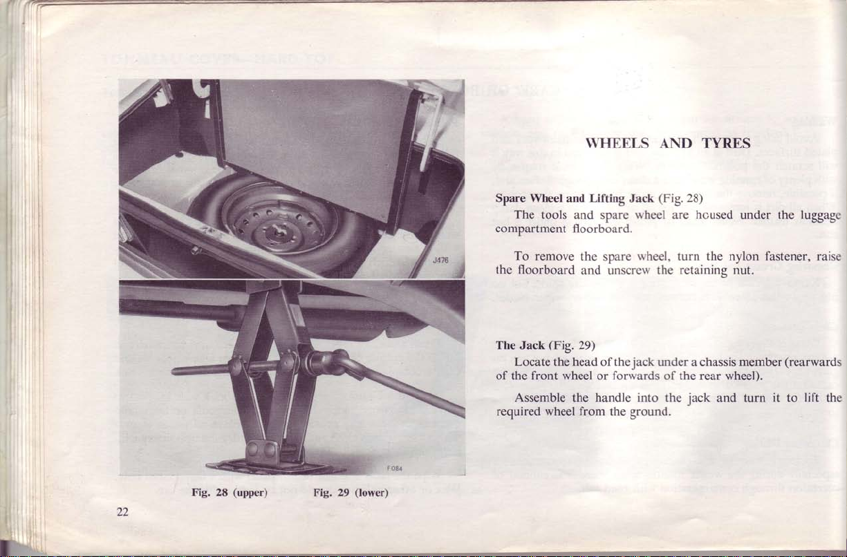
WHEELS AND TYRES
22
Fig. 28
(upper)
Fig. 29
(lower)
Spare
Wheel and Lifting Jack
The tools
compartment
To remove
the floorboard
The Jack
Locate
of the front wheel
Assemble
required wheel
and spare
floorboard.
the
and unscre\\'
$19.29)
the head of the
the handle
from
rvheel
wheel,
spare
forwards of the
or
the
the
jack
into
ground.
(Fig.28)
housed
are
turn the nylon fastener,
retaining
under
a chassis
jack
the
under
nut.
member
rear wheel).
and turn
luggage
the
(rearwards
lift
it to
raise
the
 Loading...