

Triumph TR4A Owner's Handbook Manual
HANDBOOK
TR4A
IMPORTANT
IN THE
INTERESTS
OF
SAFETY,
THE
IMPOR.
TANCE
OF MAINTAINING
CORRECT
TYRE
PRESSURES
CANNOT BE
OVER
EMPHASTSED.
PRESSURES
SHOULD BE
CHECKED
AT LEAST
EVERY
TWO WEEKS
OR
1,000
MTLES
(1600
KMS.)
AND
MAINTAINED
IN
ACCORDANCE
WITH
RECOMMENDATIONS
GIVEN
ON
PAGE
58.
TRIUMPH
TR4A
OWNERS
HANDBOOK
Issued
b!
STAN D ARD.TRI U MPH SALES LTD,
COVENTRY,
ENGLAND
A member of
the Leylad Motors
Corporation
FOREWORD
Surress,
rlre osDirution
of all human
pursuits.
has. in the
worlil of motor
sport.
bccome synonymous
with
the
nane of Triuiph.
The-many
loureli
obtained
by T,R.'s in intprnational
and locol competitions
haD?
gained
them
ait enviabie rcputotion
i7 *hi"h
,urry ownir
is
justifably
ptouil.
The newest of the
Ttiumph
thotoughbreds,
the T.R.AA,
combines
na@ deuelopments
with
the well
prou.en rally
rcsred
featuris
ol its
predicessors.
-Wc
welcom"
owaers to
on eDpr b;ilening
circle of
enthusiasts
and uish them
many-pledsont'houri
of
motoring in
aililing na o honours
to a name
alreaily renowr.eil.
To
cnsure a continuance
of
thc superb
periormonce whieh
a
-T.R,4A.is
capable
ofgiuing. coupled
with reliability
anil economy,
regular
core onil dttention
ore
neccssary. Au
essennal inJormalton
ancl
thP pcrtods
allpr unr.n
attention
is" recokmended.,
are
cotutained,
in the
following
pages, Owners
ate aih;ised
to read
them carefully
and note
particularly the
ad'aice on
lubrication'
New.parts or
accessories,
when needed,,
arc obtainable
only
through authofiseil
Triumph
dealers,
u;ho in
ad,ilition
to being trained
n
girn expert adnice
and attentiin,
are
also equipped
to utuilertahe
repairs
and
ooerhauls which
are bevonil
the scope
of most owners,
STANPART
Spare
Parts Service
Rept@ment
pdrs
are
nol supplied from
ltre facrory.Iirect
ro the
gen€ral
public,
but are
diEted throush
Distributors who,
id turn, supplv
their
cenuire
spe
parls
are markered
under rhe uade
marl Sldpan
an<t caiiy rhe same
gu&mlee
as lhe
orieinal
parr.
The" same
high
qualirv
dalerial is: u$d dd rhe srricLed
aeuracy mainrsined
duritrg
muufacture,
you
are advi$d. (heeibre.
ro iosist on
the use ol
Lbese
pans
shouro
iliii!1.;,!i,ti.;;
ii-""1,"".v.^'i;];;-b.;;i.i;iii"t
d. noirc'arrv
rhe trade
nrk stanpa(
qil
invaridare rhe
eueant@
if nlted 10
vou.
vehicre.
The .lescriorions and iltu{rarions
aDDearins
in rhis boor
are nor bindine.
The MANUFACIURER,
therefore.
rcFru€s
$e rishl-$hilst
*li','iiii if,l
"r;liil-i."'ii'Li
,liiii'iriiiir":t'ii.i,'
desribed atrd
irrusrar;d - ro
make at atry ride.
ivithour Decas&lv
brinsitre.rhis
book
;;:6:a'"i.'5ffi;";ii;;;i
i;
;"f;;';G;ori!s
aeenea
oaveueot
ror imp.oveFeat
or fo' itrv meufactu'ing
or comerciar
r€ason'
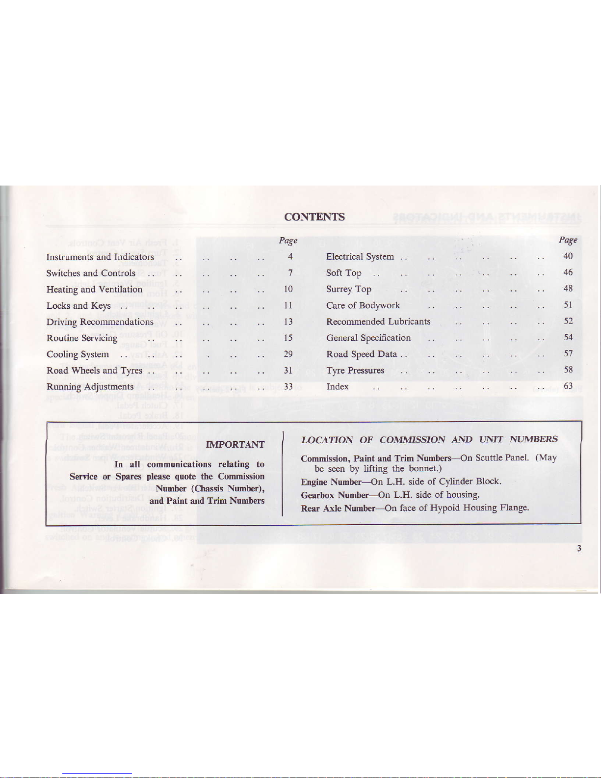
CONTENTS
Pate
4
7
l0
ll
l3
l5
29
3l
33
Instruments and Indicatols
Switches
and Controls ..
Heating and
Ventilation
Locks and
Keys ..
Ddving
Reconmendations
Routine
SeNicing
Cooling
System .. ..
Road Wheels and Tyres ..
Running
Adjustments
..
Electrical System .. ,.
soft Top ..
Surrey Top
Care of Bodywork
Recommended
Lubricants
GeneralSpecification
..
Road Speed Data..
..
Tyre Pressures
Index
Pate
40
46
48
5l
52
54
5'l
58
63
IMPORTANT
In
all
communications relating to
Service or Spares
please quote
the
Commission
Numb€r
(Chassis
Number),
and Paint and Trim Numb€rs
I-OCATION OF CO]IIDtrSSION
AAID
LINIT
]\{IMBERS
Commission,
Paint and
Trim Numbers-On
Scuttle
Panel.
(May
be seen
by lifting the bonnet.)
Engine
Number-On L.H. side
of
Cylinder
Block.
Gearbox
Number-On L.H. side
of housing.
Rear
AxIe Number-On
face of HyPoid
Housing Flange.
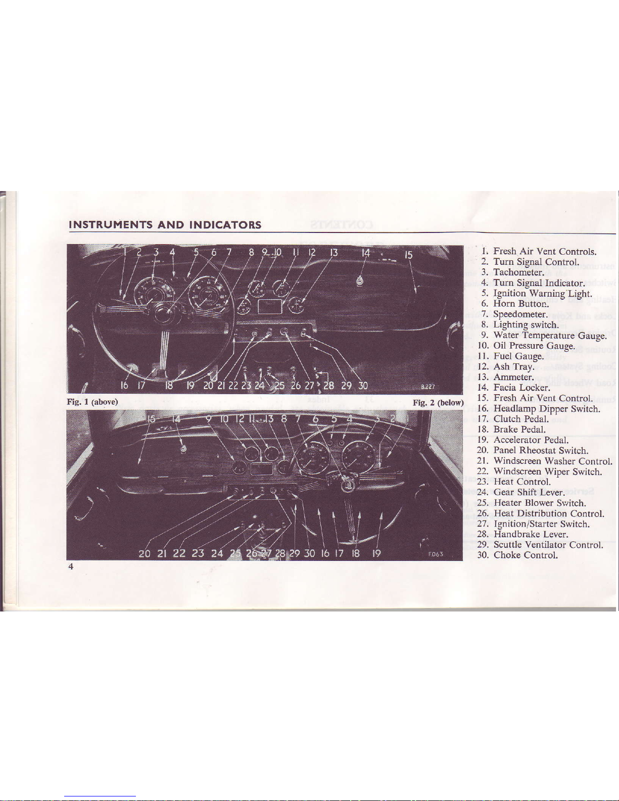
INSTRUMENTS AND INDICATORS
Fig. 1
(above)
Fig. 2
(below)
l, Fresh
Air Vcnt
Controls.
2.
Tum
Signal Control.
3.
Tachometer.
4. Turn
Signal
Indicator.
5. Ignition
Waming
Light.
6, Hon Button.
7.
Speedometer.
8. Lighting
switch.
9. Water Temperature
Gauge.
10.
Oil
Pressure
Gauge.
I l. Fuel
Gauge.
12. Ash Tray.
13, Arruneter.
14. Facia Locker.
15,
Fresh Air
Vent Control.
16.
Headlamp Dipper
Switch.
17. Clutch Pedal.
18. Brake Pedal.
19. Accelerator
Pedal.
20.
Panel Rheostat
Switch.
21, Windscreen Washer
Control.
22, Windscreen
Wiper
Switch.
23. Heat Control.
24.
Gear Shift Lever.
25. Heater
Blower
Slvitch.
26. Heat Dist
bution
Control.
27.
Ignition/Starter
Switch.
28. Handbrake
Lever.
29. Scuttle Ventilator
Control.
30. Choke Control.
INSTRUMENTS
AND
INDICATORS
INSTRUMENTS
AND I]\DICATORS
The instruments,
indicators
and controls shown on Figs.
I
and
2,
and
indicated in brackets within the text,
perform
the
following functions:-
Tachometer
(3)
The
tachometer, indicates the
engine
speed in revolutions
per minute and is calibrated in divisions of 100, extending
to
6,000. The speed
range
within the red segment
is subject to
special
precautions. These are giyen on page 14.
Turn Sienal Indicator
(4)
The green
flashing
indicator monitor light, glows intermit-
tently when the
direction
control is operated and
the ignition
is switched on. See
"T\rm
Signal Control" on page 9.
Flesh
Air
Vents
(1
and 15). Refer
to page
10.
Ignition Wamiry Light
(5)
The small
red warning
light glows when
the ignition
is
switched on and is extinguished when the engine
is
acc€lerated.
Should the indicator
continue to glow
when the engine is running
above idling speed
an electrical
fault is indicated li,hich should be
traced and
rectified
immediately.
Spe€dometer
(7)
The speedometer
indicates
the road speed of the vehicle
in
miles
per
hour and is calibrated
in divisions of
2, extending to I 20.
The fiqures within
the aperture above
the centre of the dial
may be fsed
to record individual
joumeys.
Provided
that the
figures
are re-set to
zero at the beginning.
This is achieved by
pushing
up and
turning clockwise
the knob
which
extends
downwards
from behind the
instrument.
The figures within
the aperture below
the c€ntre of the dial
show the total
mileage of the v€hicle
ard may be used as a
guide
for
periodic
lubdcation and
maintenanca.
The High Beam indicator
near the bottom
of the dial glows
only when the
headlamp main beams
are in use. When the
diPper
switch is operated
tbe indicator is extinguished.

INSTRUMENTS AND INDICATORS
Water Temperature
Gauge
(9)
Normal operating temperature
is reached when the needle
registers in the
central sector of the dial. Should the needle
reach the highest mark,
stop the engine immediately, allow it to
cool and check the level of the
coolant
in the radiator.
When the
ignition is
switched on
the
needle moves slowly across its scale,
taking up
to
one
minute
to reach a true rcading.
Oil Pressure Gauge
(10)
The oil pressure relief valve is set to
control the pressure at
65-75 lb. per sq. in. at 2,000 r.p.m. with normal
oil temperatures.
i.e.,
about ?O'C. During sustained high speed operation,
th
resulting increase in oil temperature may
cause
the
oil pressur
to drop. This will have no detdmental effects
providing it do(
not fall below 30 lb. per
sq.
in.
Severe operating conditions, such as competition work, ma
cause the oil pressure to fall below 30 p.s.i., indicating that the
o
temperature is excessive. Under these circumstances,
an o
cooler kit is recommended to ensure that a maximum
sump o
temperature of 125"C. is not
exceeded.
Fuel
Gauge
(ll)
The fuel
gauge indicates the approximate
contents
of tt
fuel
tank. When the ignition is switched on, the needle mov(
slowly across its
scale taking up
to
one
minute to reach a stead
reading which
it will maintain, regardless of vehicle movemen
unril the ignition is
switched
otr
Ammeter
(13)
The ammeter is calibrated in amperes and indicates the ra1
of battery charge and discharge. The charging rate is indicat€
when
the
pointer
moves to the left-hand side of
"zero",
an
discharge.
b) movement to the right.
SWITCHES
AND CONTROLS
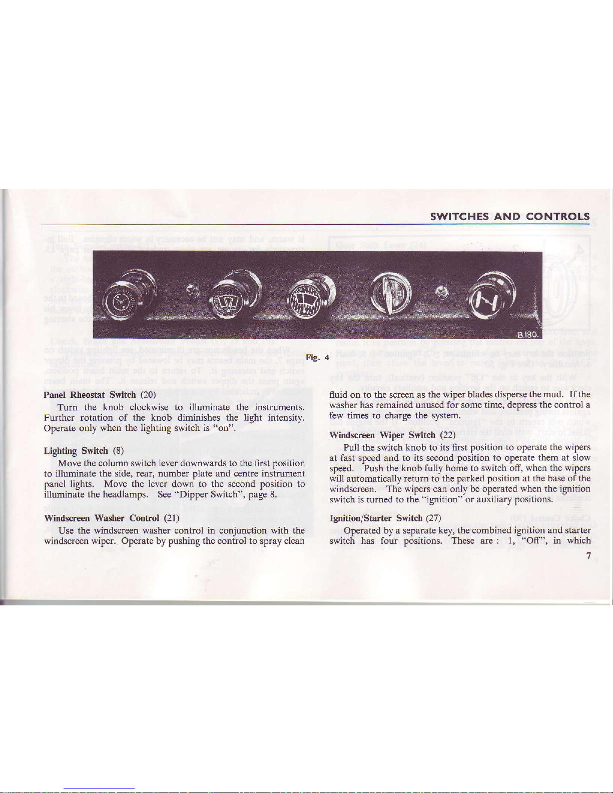
Fig. 4
Panel R.heostat
Switch
(20)
Turn the knob clockwise to illuminate the
instruments.
Futher rotation
of the knob
diminishes
the light intensitv.
Operate
only when
the lighting
switch is
"on".
Lighting Switch
(8)
Move the column switch
lever
downwards to the fust Dosition
to illuminate
the side, rear, number plate and centre instrument
panel
lights. Move the lever down to the s€cond position to
illuminate the headlamps. See
"Dipper
Switch", page 8.
Witrdsq€en
Washer
Control
(21)
Use the
windscreen washer cootrol in coniunction with the
windscreen
wiper.
Operate by pushing the conirol to spray clean
fluid
on
to the screen as the wiper blades dispers€
the mud. If the
washer has remained unused for some
time, depress the control a
few times to charge
the
system.
Windsqeen Wiper Switch
(22)
Pull the switch knob to its first position
to operate the wipers
at fast speed and to
its
second
position to operate them at slow
speed.
Push the knob fully home to switch off, when
the wipers
will automatically return to the parked
position at the base of the
windscreen. The wipers can only be
operated when the ignition
switch is
turned to
the
"ignition"
or auxiliary positions,
Ignition/Starter Switcb (27)
Op€rated
by a separate key, the combined ignition and stalter
switch has
four positions. These are: l,
"Off",
in
which
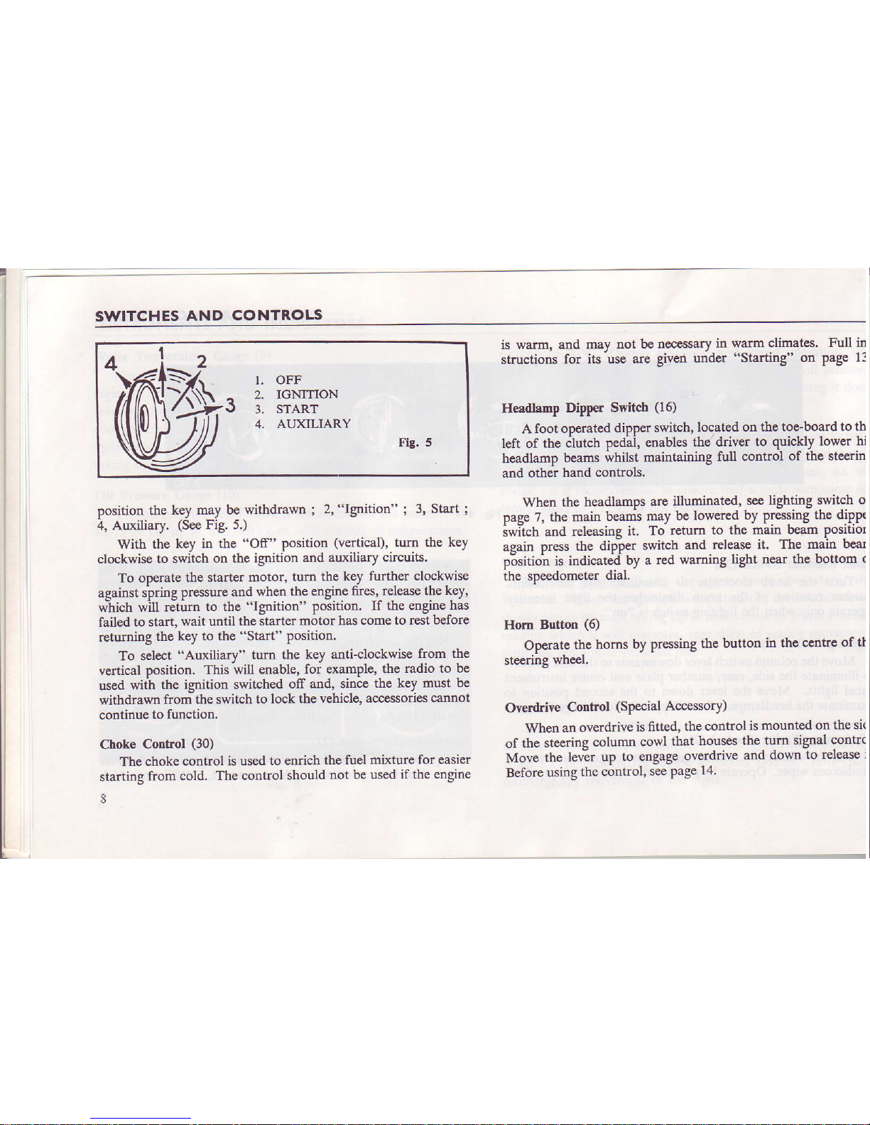
SWITCHES
AND CONTROLS
I. OFF
^
2. IGMTION
J
3. srART
4.
AIIXILIARY
Flg.5
position
t}Ie
key may be
withdrawn
;
2.
"Ignition"
;
3,
Start
;
4.
Auxiliary.
(See
Fig. 5.)
With
the
key in the
"Off"
position
(vertical),
turn the
key
clockwise
to
switch on the ignition
and
auxiliary circuits.
To operate
the starter
motor, turn
the key further
clockwise
against spring
pressure
and
when
rhe engine
fires. release the
key.
*hich
*il-t retum
to the
"lgnition"
Position.
It the enBineias
failed to start,
wait
until
the starter
motor has come
to rest befbre
retumiug
the
key to the
"Start"
Position.
To
select "Auxiliary"
turn
the key anti-clockwise
from the
vertical
position.
This
will enable,
for €xamPle, thc
radio to be
used
witj\
the ignitioo
switched
off and, since
the key must
be
withdrawn
fronithe
switch to
lock the
vehicle, accessodes
cannot
continue to
function.
Choke
Control
(30)
The choke
control is used
to enrich
the fuel
mixture for easier
startiog
from cold.
The control should
not be
used if the engine
3
is warm.
and mav
not be oe€gssary
in walm
climates. Full in
structions
for
its'use are given
urider "starting'
on
page 13
Headlamp
Dippr Switch
(16)
A
foot operated
dipper switch,
located on the toe-board
to th
left of the itutctr
peAai,
enables
the ddver
to
quickly
lower bi
headlamp beams
whilst
maintaining
full
conhol of th€ stocrin
and othar
hand
controls.
When
the headlamps
are
illuminated,
see lighting
switch o
page
7. the main
beams
may be lowered
by pressing
the dippe
iwi-tch
and
releasing
ir. To
retum lo the
main beam
Positior
apain
Dress
rhe dipier
switcb
and
release ir. The
main bear
p6sition
is indjcate'd'
by a
red
waming liSht near
the bottom
(
ahe speedometer
dial.
Hom Button
(6)
Operate
the
homs by
prcssing
the button
in the c€ntre
of tt
steering
wheel.
Overd
ve Control
(SPecial
Accessory)
When
an
overdrive
is fitted,
the control
is
mounted on
the si(
of the
steering
column
cowl
that
houses
the turn signal
contrc
Move
the lever
up
to engage
overdrive
and down
to release
i
Before
using
the control,
see
page
14
SWITCHES
AND CONTROLS
Turn
Signal
Control
(2)
The turn signal
lamps are controlled by a
lever
mounted on
the outboard side
of the steering column cowl.
Before making
a right-hand
turn, move the
lever
clockwise.
Move it anti-
cloc[wise
before
tuming left. When either left- or right-hand
turn signal
lamps are operating, a green indicator
light on the
facia,
flashes intermittently,
Clutch,
Brake and
Accelerator Pedals
(17,
18 and 19)
These are
conventional items which do
not
need
further
explanation.
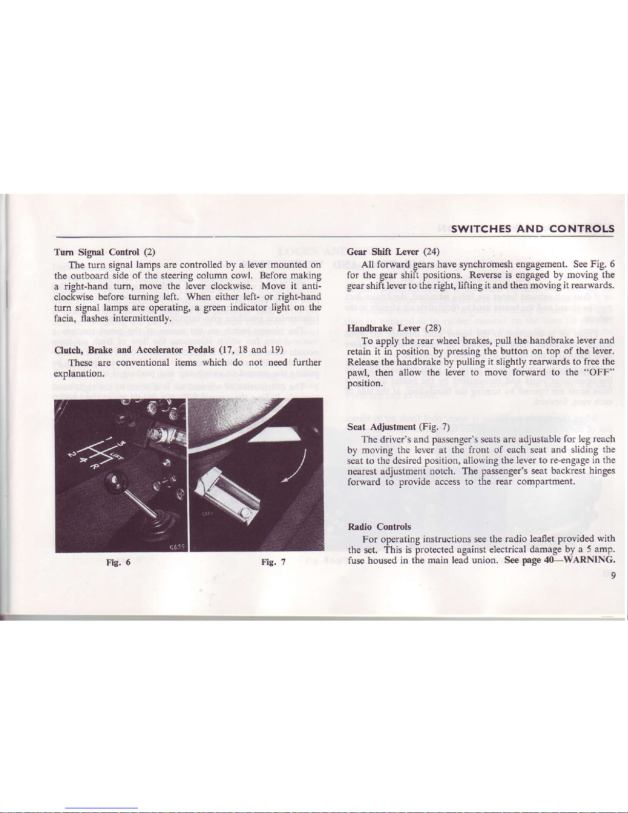
Gear Shift
Lever
(24)
AU forward geals have synchromesh engagement. See
Fig. 6
for the gear shift positions.
Reverse is engaged by moving the
gear shift
lever to the right, lifting it and ther
moving it rearwards.
Handbrake Lever
(28)
To apply the
rear
wheel brakes, pull
the handbruke lever and
retain it in
position
by pressing the button on
top of the lever.
Release the handbrake by pulling
it slightly rearwards to free the
pawl, then
allow the lever to move forward
to the
"OFF"
position.
Seat
Adiustment
(Fig.
7)
The driver's
and passenger's seats are adjustable
for leg reach
by moving
the lever
at
the front of each seat and sliding
the
seat to
the desired
position,
allowing the
lever to re-engage in the
nearest adjustment notch. The passenger's
seat backrest hinges
forward to provide
access to the rear compartment.
Radio
Controls
For operating
instructions see the rudio leaflet provided
with
the set.
This is protected against electrical
damage by a
5 amp.
fuse housed in
the main lead union. See page 40-WARNING.
HEATING
AND
VENTILATION
IIEATING
AND
The heater is designed to heat and distribute incoming fresh air,
or if dust and exhaust fumes are being admitted, thc intake
duct
may be closed and
the heater
used
to recirculate air aheady in the
vehicle.
Fresh air is admitted to the heater duct tirough the open
scuttle ventilator, This is opened by pulling
t}le ventilator
leyer rearwards and closed by
pushing
it forwards.
When the scuttle ventilato! is closed, air
is
drawn
in tbrough
the open facia vents and recirculated by the heater unit, The
facia vents are opened by turning the handwheel, at
the side of
each
vent, forward.
When
the
scuttle ventilator is open,
cool fresh air is blown
out of the open facia vents and may be directed up or down,
or
may be cut-off by adjusting
the
handwhe€l.
There is no provision
for heatine the air blown from the facia vents.
Vf,NTILATION
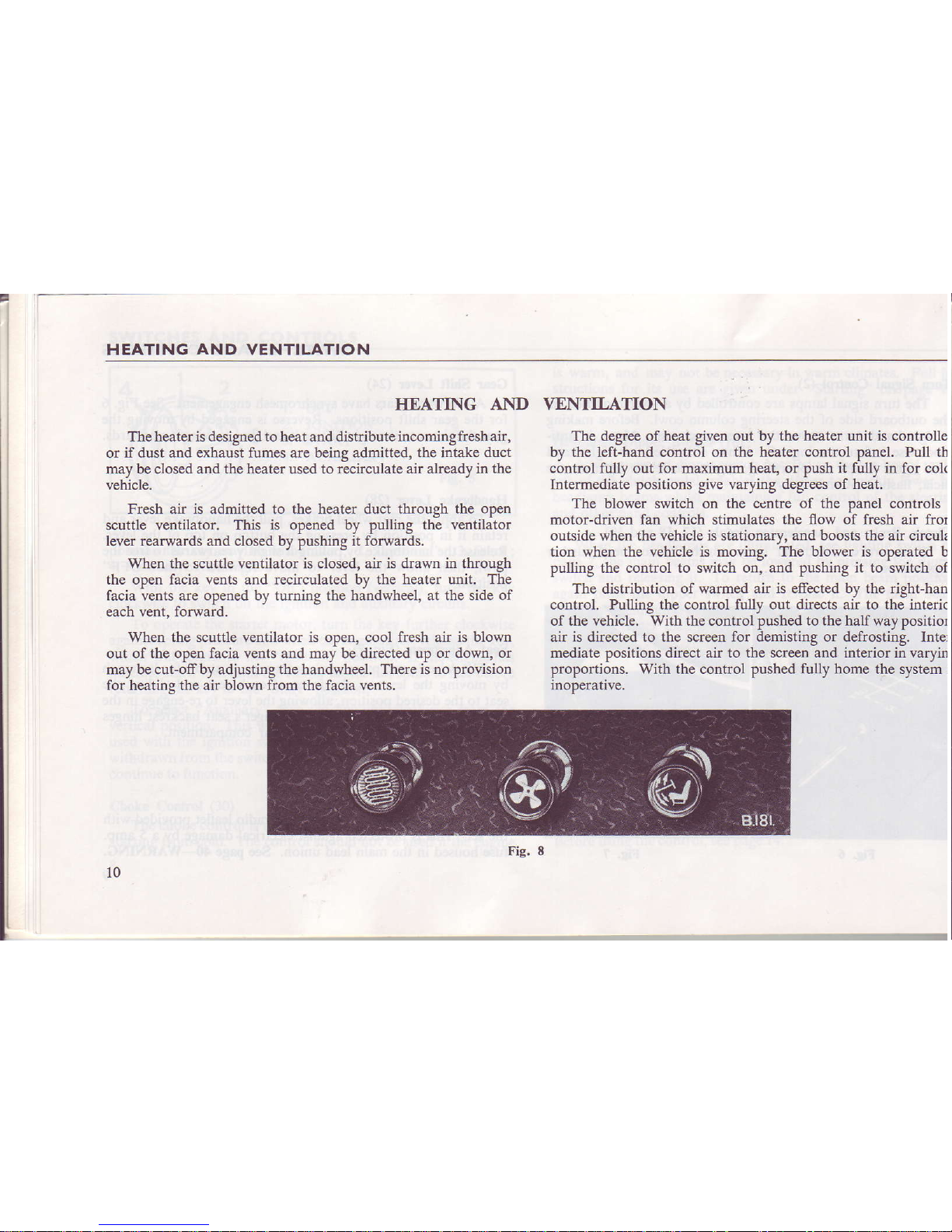
The degree of heat given out by the heater unit is controlle
by the left-hand control on the
heater conhol panel. Pull
th
control fully out for
maximum
heat, or push it fully in for colc
Intermediate positions give varying degees
of heat,
The blower switch on the ccntre of the panel controls
motor-driyen
fan which
stimulates
the flow of fresh air fror
outside when the vehicle is stationarv. and boosts the air cftculs
tioo
when the vehicle is moving. The blower is operated b
pulling the control to switch on, and pushing it to switch of
The distribution of warmed air
is
effected
by
the right-han
control.
Pulling the contuol fully out directs air to the
intedc
of the vehicle. With the control pushed to the half
way
positior
air is dire€ted to the screen for demisting or defrosting. Inter
mediate
positions
direct ak to the screen and interior in varyin
proportions. With the control pushed fully home the system
j
inoDerative.
Fig. E
10
LOCKS AND KEYS
LOCKS
Locks and Keys
Two sets of keys are provided. One
key is used for operating
the ignition switch and door locks, and the other for
locking the
facia locker and
luggage
compartment.
The
spare
set of keys
is housed
inside the rear lamp at
the passenger
side. You are
advised
to record the key number for future reference, so
that
in the event of
loss, replacement keys may be obtained without
diffculty.
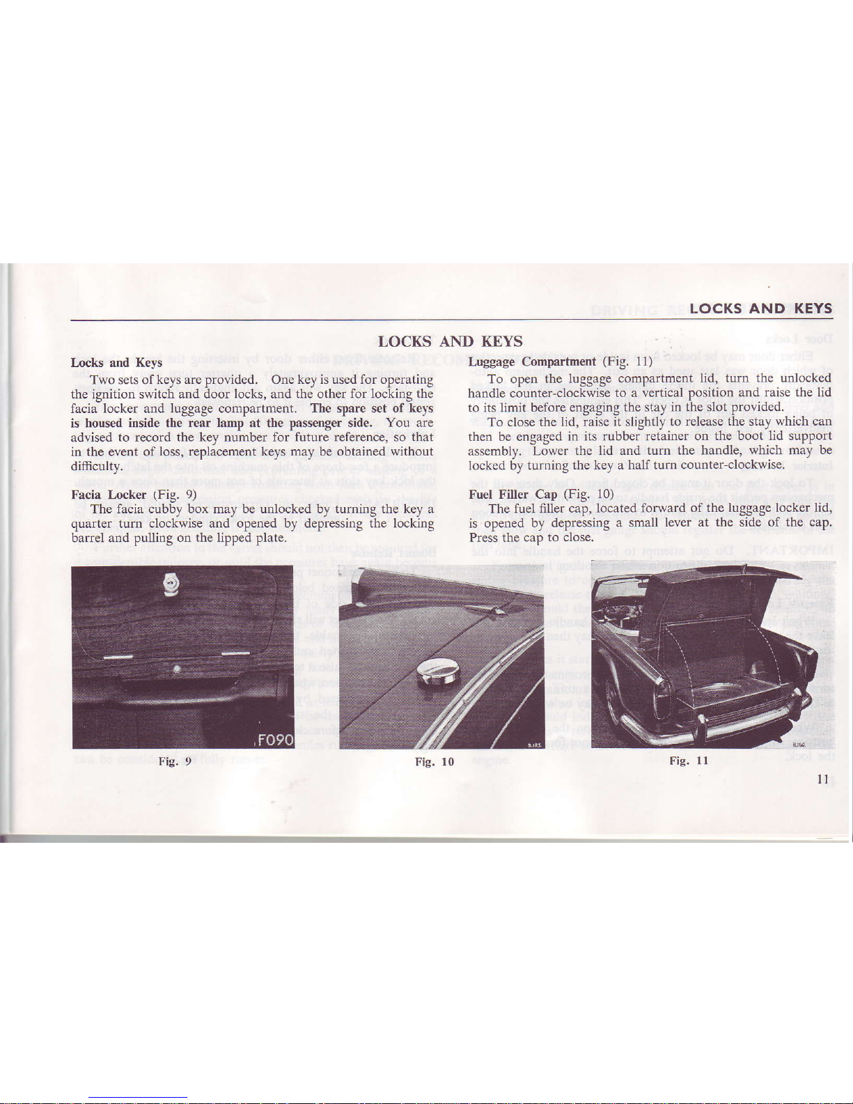
Facia Locker
(Fig. 9)
The facia cubby box may be unlocked by turning the key a
quarter turn clockwise and opened by depressing the locking
barrel and pulling
on the lipped plate.
AND KEYS
Luggage Compartment
(Fig.
1l)
To open the luggage
compartment lid, turn
the unlocked
handle counter-clockwise
to a vertical position
and raise the lid
to its limit
before engaging the stay
in the slot
Provided.
To close the lid,
raise it slighdy to
release the
stay
which can
then be engaged
in its rubber retainer
on the boot lid suPPort
assembly,
Lower the
lid
and
turn the handle, which
may be
locked by turning
the key a half turn
counter-clockwise.
Fuel Filler Cap
(Fig.
10)
The fuet
fitler cap, located forward
of the luggage locker lid,
is opened
by depressing a small
lever at the side
of
the
cap.
Press the caD
to
close.
Fic.
ll
ll
LOCKS
AND KEYS
Door Ircks
Either door may be locked from inside or outsidc
irrespective
of
which
door
was last
used
as an exit, The mechanism auto-
matically prevents the inside handle being
set in the locked
position whilst the door
is
open.
This eliminates the possibility
of being locked out of the car in the event of the
key being
inadvertently left inside.
Interior
Locking
To lock the door it must be closed fust. Only then will the
mechanism pemit the inside handle to be moved forwards.
The
handle
will
automatically
retum to the normal
position
as soon
as it is released.
IMPORTANT. Do not attempt to force the
handle into the
locked
position
whilst the door is. open.
Exterior Locking
When leaving the car, move the door
handle forward and
leave the
vehicle by the other door, which may then be locked by
using the key as follows :-
Inse the key in the lock and turn it approximately a quarter
tum towards
the
shut-face.
The key will automatically retum
to rhe horizontal position from wheie it may be
wirhdriwn,
when the dools are locked, pressurg
on the outside push
buttons,
which may be fully depressed, cannot
force or damage
the lock,
l2
To UDlock
Re-enter from either
door by inserting
the key in the lo(
and tuming
it approximately a
quarter tum away
from
tl
shut-face. The
key will again automatically
return to the hor
zontal position
to enable it to
be removed.
Lubrication
It will be beneficial, particularly
during
freezing
weather,
l
fuifoduce a few droDs
of thin machine
oil into the latch slot ar
the lock
key
slots
ai intervats
of not more than once a mont
IMPORTANT. Urder no
circumstances should grease
I
applied
to the lock cylinders
or keys.
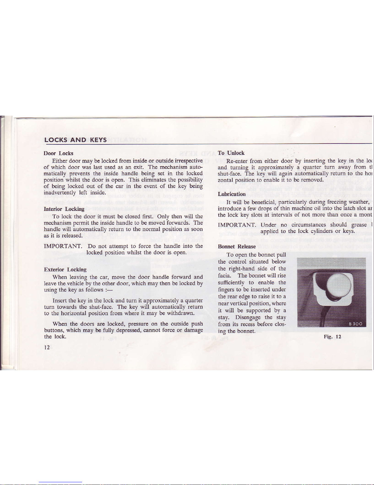
Bomet
Release
To open the bonnet pull
the contuol situated
below
the right-hand side
of tlle
facia. The bonnet will
rise
sufficiendy
to enable the
fingers to be
inseded under
the rear edge to raise it to a
near
vertical position,
where
it will be supported by a
stay. Disengage
the
stay
from its recess before clos-
ing the bonnet.
Fie. 12
DRIVING
RECOMMENDATIONS
DRIVING RECOMMENDATIONS
Running-in
The
importance of correct running-in cannot be too strongly
emphasized, for during the f,Ist 500 miles of motoring, the
work-
ing surfaces
of a new engine
are bedding
down.
Du
ng this
period
the valve
seats stabilise,
causing in
some
instances, slight distortion and preventing proper seating of a
valve.
Avoid
possible
damage resulting from
such a condition,
by
having the compression pressures checked early in the life
of the engine after
"running-in"
is completed.
If the
pressures
are unequal,
valve
grinding
is recommended.
Further attention to the valves should not then be required for
a considerable
mileage,
or
until the
pressures
have again become
unequal.
Whilst no specific speeds are recommended during the
running-in period,
avoid
placing
heavy loads upon the engine,
such as using full throttle at low speeds or when the engine is
cold. Running-in
should be
progressive and
no harm will result
from the engine being allowed to
"rev."
fairly fast provided that
it is thoroughly
warm
and
not
pulling hard.
Always
select a
lower gear
if necessary to relieve the engJne of load.
Full power should not be used until at least 500 miles have
been covered
and even then, it
should
be
used only
for
short
periods at a time. These periods can be extended as the engine
becomes
more responsive. After 1,000 miles running, the engine
can be considered as fully run-in.
Starting the
Engine
from Cold
Check,
and
if necessary top up, the
radiator water level and
the engine oil
level. If the car
has not been used for several days
and
fuel has evaporated
from the carburettors,
refill them by
operaling the
priming lever on the fuel pump.
The slight resistance
ciuses wEen the floaichambers
are fu .
Apply the
handbrake and ensure
that the gear lever is in
"Neutral".
Pull the choke
control out to
its
stop and
tum the
key to the
"ignition"
position.
The ignition
waming light should
then
glow
and
the fuel gauge
should register the contents of
the
fuel tank.
From the
"ignition"
position,
tum the key clockwise against
spring
pressure ro operate the slarter motor.
lmmediatel) lhe
eigini
hres. release the key.
which will rerurn to the
"igniiion'
position.
Should the
engine fail to start at
the first attempt, do
not re-operate
the starter switch until
the starter motor has
come
to
test.
As soon
as it starts, push
the choke to the
"half-in"
position
and warm the engine at a
fairly fast idling speed
of approximately
1,500 r.p.m.
This will cause the
ignition waming light to
be
extinguished, thus indicating
that the generator is
charging. The
oil gauge should
indicate the pressure
of oil circulating. lf the
gauge
remains at zero, stop
the engine immediately and
establish
the cause.
Failure to do so may
result in serious damage to the
eDgroe.
DRIVING RECOMMENDATIONS
Cylinder wear is minimized ifthe engine is warmed
up quickly
by driving away as soon as oil is circulating after
stading the
engine. Do not race the
engine to speed up the process but, if
possible, maintain a speed of approximately 25 m.p.h.
until the
choke can be
pushed
fully in.
In
warm
climates, use of the choke
may be unnecessary. Avoid the
use of full throttle during the
warmiog-up period. A themostat incorporated in
the cooling
system
enables the engine to
be
warmed
up quickly from cold.
Starting with the Engine Warm or Hot
When
re-starting
a hot engine, depress the accelerator
pedal
to about one-third ofits travel
before operating the starter switch.
The choke conrrol should not be used.
Recornmetrded Speed Limits
Avoid over-rewing,
particularly in the iower gears. The driver
is advised not to drive the
car continuously atengine speeds above
5,000 r.p.m.
in
any gear. However, whilst accelerating
through
the
gears
it is
permissible
to
attain 5,500 r.p.m. for short periods,
these speeds being indicated
by the beginning and the end of the
red segment on the tachometer.
When an overdrive
is fitted, do not change from overdrive
to normal 3rd or 2nd
gears
at
engine speed exce€ding 4,500 r.p.m.,
otherwise damage may result from
"over-rewing".
Overdrive Unit
(when
fitted)
Ao overdrive unit senes
as a convenient method ofproviding,
at wili, a numericalll lower
overall gear ratio ro redice enginl
speed and wear, and to efect fuel
economy,
t4
The Laycock de Normanville
overdrive unit incorporal
an
epicyclic gear train which is engaged,
to give overdri
condition,
by a cone clutch moving under the influence
of t
hydraulic
pressure genemted by a small piston pump. Wh
pressure is released, via a control valve, the
clutch is return
and held
in direct drive by compression
springs, A ur
directional roller
clutch enables the change into, or out
(
overdrive to be made when transmitting
full power, without lc
of road
speed.
The hydraulic
control valve is linked to an electro-magne
solenoid which is operated, via a relay,
by a two-position swit
mounted
on the stee ng column.
Greatest benefit
will
accrue from
judicious
use of the ov(
drive, the
governing
factor
being
that
the vehicle continues
run
easily without sign of engine labouring,
combined wj
the ninimum
amount of throttle opening necessary to mainte
this condition.
Suggested
minimum
engagement speeds are:-
Top gear 40 m.p.h.
Third gear
30 m.p.h.
Do not change from overdrive to normal drive
at engj
speeds in excess of 4,400 r.p.m.
The above disengagement
speed corresponds approximatl
to peak revs.
in
norrnal gears. Disengagement of the O/D
a speed higher than that
stated
may
cause damage fr(
"over-revving".
ROUTINE SERVICING
ROUTINE
This section describes the lubrication and servicinq requirements which are neaessary to maintain tbe vehicle in g6od order
and ensure trouble-free motodng. All points desc
bed
should
receive attention at the prescdbed intervals,
Engrne
When a new car is delivered, the engine sump contains a
special
running-in oil
which should be retained until the completion of 1,000 miles. Although the level may not reach the
high mark on the dipstick, the
quantity of oil
is
sufficient
for
the
running-in pedod.
Provided
the level is maintained between
the low and high marks on the dipstick, during this
period,
topping-up
is unnecessary.
At the
"Free
Seryice",
the running-in oil is drained
and
the
sump
replenished to the leyel
of
the high
mark on the dipstick,
with one of
the
approved oils recommended on pages 52 and 53.
Gearbox.
OYerdriYe and Rear
Axle
Rear
axles, gearboxes and overdrive units fitted to new cars
are filled with a special oil, formulated to
give all necessary
protection
to new gears. This
oil should
not
be drained but may
be topped up with any
of
the
approved oils
listed
on pages 52
and 53
against the
appropriate uDit.
SERYICING
Lubrication
When carrying out the
following maintenaDce
work, the
importance of using only high
grade
lubdcants is
yitallv
important and canrot be over emphasised
These lubricants have mainta,ined a high standard of
quality over
many
years and are
recommended
only
after extensive tests in collaboration with the oil companies
concemed. In count es where these oils are unobtainable, use
similar
high
grade
oils having the same characteristics,
PreYentive Maintenance
To ensure continued emciency and prolonged vehicle life,
the maintenance
voucher
schem€, produced by Standard-Triumph
engineers, ofers a carefullv designed
plan
of lubrication require-
ments and adjustment checks at predetermined periods.
Operated by all Standard-Triumph dealerc, and specifically
recommended
to
owners wishing to obtain the greatest pleasure
from thei motoiing, the scheme involves the use of a sedes of
Maintenance
Vouchers
contained in a booklet suDDlied with the
car.
Service Operations appropriate ro mileage or
periods
of
time are listed on pages
preceding
the vouchers.
The space
provided on the counterfoil ofeach
voucher
should
be filled in by the owner and dealer to constitute proof of regular
seryicing,
should this
be
required when
making a claim under
the wananty, or when selling the vehicle.
IJ
ROUTINE
SERVICING
FREE
SERVICE OPERATIONS-
Radiator
Level
Engine
Sump
Cylinder
Head
Fuel Pump
.. ..
CarburettoIs
Accelerator
controls,
linkage,
pedal,
fulcrum ..
Fan
Belt
Valves
Manifolds
.. ..
Oil
Filter
Clutch
Pedal Pivot .. ..
Master Cylinder
Hydraulic
Pipes
Gearbox
Overdrive
Rear Axle
.. ..
Universal
Joints
Lower Steedng
Swivel .,
wheel Alignment ..
..
Steering
Unit Attachments
and
"U"
bolts .. ..
Tie Rods and
Levers
l6
Check
Drain/refill
Check
tightness
Clean filter
and sediment
chamber
Top up dashpots
Adjust slow
running
oil
Adjust tension
Adjust
clearanc€s
Check
tightness
Examine
for
leaks
Lubricate
Check;
top
up
Check
leakage
Check
level-top up
Check
level-top
up
Check
tightness
Lubdcate
Check by
condition
of tyre treads
Check
tightness
Check
tightness
Handbrake
Cable
Linkage..
Hydrautic
Pipes
Master Cylinder
Pedal
Pivot .. ..
Brakes
Handbrake Cable
..
..
Battery
Generato! ..
..
Generator
and
Starter
..
Distdbutor ..
..
Sparking
Ptugs
Headlamps
..
..
Lights,
He ater,
screen
washer, Wiper
and Warn-
ing Equipment
..
..
WheelNuts,.
..
Tyrc
Pressures
Door Strikers,
Locks,
Hinges
Body Mounting
Bolts
. .
Door Handles,
Controls
and
windshield
Lubricate
Check for
leakage
Check/top
up
Lubricate
Adjust
if nocessary
Adjust
if necessary
Check/top
up
Lubricate
reax
beaing
Check
charging
rate
Chack
fixing bolts
for tightncss
Lubdcate
and adjust
points
Clean
and reset
Check alignment/adjust
Check
operation
Check
tightness
Check/adjust
Check
operation/oil
Check
tightness
Wipe clean
ROUTINE
SERVICING
PERIODICAL
ATTENTION
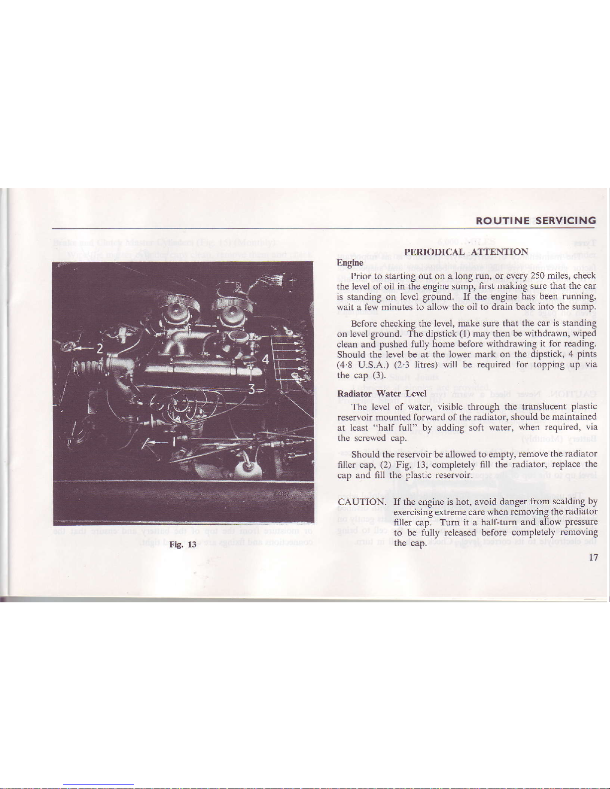
Engrne
Prior
to starting
out on a long run, or every
250 miles, check
the level of oil in the engine sump,
fust making sure that the car
is standing on
level
ground.
If the engine has been
running,
wait a few minutes
to allow the oil to drain back
into the sumP.
Before checking the
level, make sure that
the car is standing
on
level
ground.
The dipstick
(l)
may then be withdrawn, wiped
clean and pushed fully home before
withdrawing
it for reading.
Should the
level be at the lower mark on
the dipstick, 4
Pints
(4
8
U.S.A.)
(2
3 litres) will be
required for topping up
via
the cap
(3).
Radiator
water l,€Y€l
The
level of water, visible through
the translucent plastic
reservoir mounted forward of the radiator,
should be maintained
at least
"half
full" by adding soft
water,
when required, via
the
screwed
cap.
Should the
reservoir be allowed to empty,
remove the radiator
filler cap,
(2)
Fig. 13, completely
fill the radiator,
rePlace the
cao and fill the rlastic reseryoir.
CAUTION. If the engine
is hot, avoid danger
from scalding
by
exercising extreme care when
removing
the radiator
filler cap. Tum
it a half-turn and
allow pressure
to be fully released before
comPletely
removing
me cap.
Fig. 13
ROUTINE
SERVICI NG
Tyres
The
maintenance of corect tyre
pressure
is
an
important
factor
governing tyre life,
steering behaviour aod suspension.
It is, therefore, important
that a check on tyre
prcssurc
is made
regularly at periods
not
exceeding one month,
and the losses,
due to diffusion, are n-ude
good. Correct tyre
pressures are
given on page 58.
Adjust the pressures whilst
the tyres are cold,
i.c., belore a
run. As the tyres warm
up their pressures
may increase as much
as 5 to 6 lbs. per sq. in. depending
upon the type of tyre and the
severity of driving.
CAUTION,
Never
bleed a warm
tyr€ to the recommended
pressure.
Battery
(Monthly)
Examine the level
of the electrolyte
in the cells and, if neces-
sary, add distilled water
via the plugs
(4)
Fig.
13, to bring the
Ievel up to the
top of the
sepamto$.
The use of a Lucas
Battery Filler will
be
found
helpful when
topping-up.
Ensure that
the Battery Filler is 6lled
with distilled
water
and
jnsert
it into
a filler
plug
orifice until it
rests gently on
the separaton.
Sufficient water
will pour into the cell to
bring
the electrolyte
to its corect
level. Check each cell
in turn.
l8
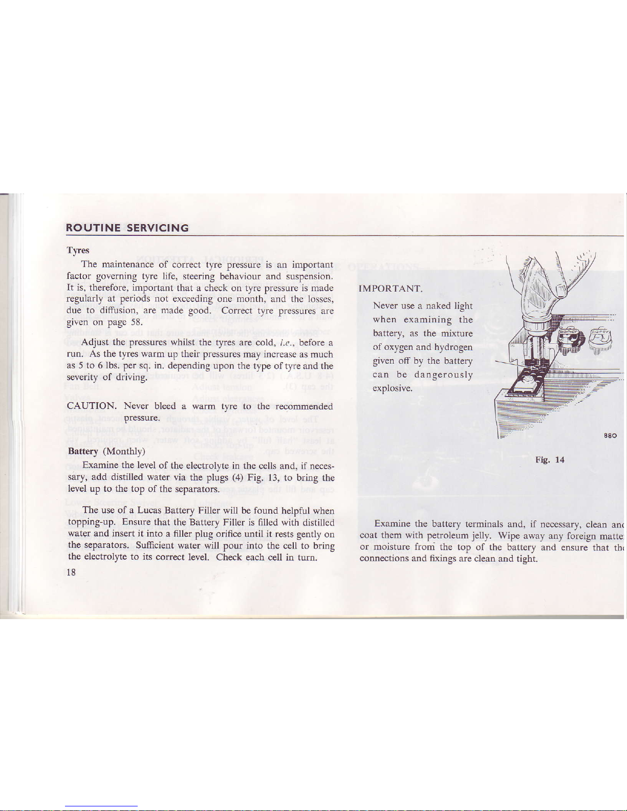
IMPORTANT.
Never
use a naked light
when examin
ing the
battery, as the
mixture
of oxygen and hydrogen
given off by the battery
can be
dangerously
explosive.
Fig.
14
Examine
the battery terminals
and, if necessary,
clean
anc
coat them with
petroleum
jelly.
Wipe away any
foreign matter
or
moisture froni the top
of the battery and
ensure that th(
connections
and nxings
are clean and tight.
ROUTINE
SERVICING
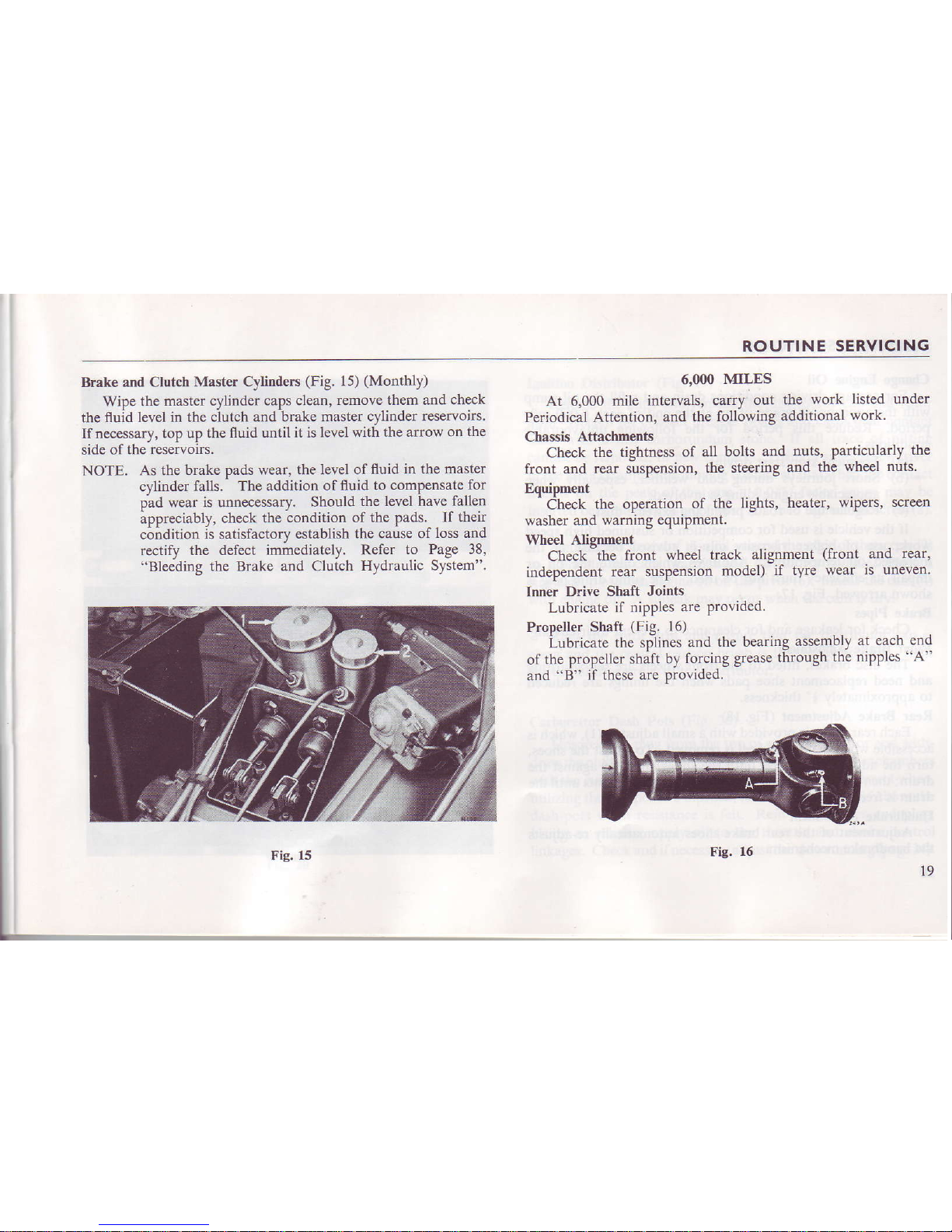
Brake and
Clutch
Master Cylinders
(Fig.
15)
(Monthly)
Wipe the master cylinder
caPS clean.
remove them and
check
the fluid level in
the clutch and brake
master cylinder
reservoirs.
Ifnecessary,
top up the
fluid until it is level
with the alrow on
the
side
of the reservoirs.
NOTE. As the
brake
pads
wear.
the leyel of fluid in the
master
cylinder
falls. ^ The
addition of fluid
to comPensate
for
oad wear
is unnecessarv. Should
the level have
fallen
ippreciably,
check
the tondition of
the
Pads.
If their
condition
is satisfactory establish
the cause of
loss and
reatify the defect
inlmediately. Refer
to Page 38,
"Ble€ding the Brake and Clutch
Hydraulic System".
6,000
MILES
At 6,000 mile
intervals, carry
out
the work
listed under
Periodical Attention,
and the
following
additional
work.
Chassis Attachments
Check
the tightness
of all bolts
and
nuts,
Particularly
the
front and rear suspension,
the steering
and the
wheel nuts.
Equipment
'Check
the operation
of
the lighls.
heater.
wiPers. screen
washer and
wamlng equlPmenr.
Wheel Aliqnment
Check
-the
front
wheel track
alignment
(front
and
rear,
independent rear
suspension
model)
if tyre
wear is uneven.
Inner
Drive Shaft Joints
Lubricate if
nipples are
Provided.
Propeller Shaft
(Fig.
I6)
iubricate the sp-line:
and
the bearing
assembly
at each
end
of
the propeller shaft
by
forcing grease
through
the nipPles
"A"
and
"B" if these are provided.
Fig. 15
Fig.
16
l9
 Loading...