

Page 1

Page 2

INSTRUCTION BOOK
Part No. 501528
TRIUMPH
SPORTS CAR
TR3
SIXTH EDITION
Third Printing
Issued by
STANDARD-TRIUMPH SALES LIMITED
COVENTRY, ENGLAND
Page 3
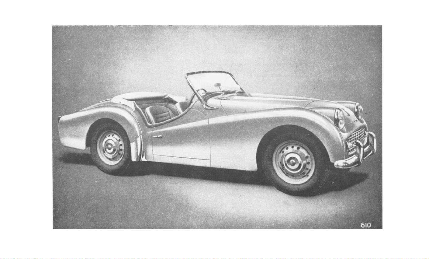
Fig.1.'THE TRIUMPH TR3 SPORTS CAR
Page 4

FOREWORD
Triumph vehicles are so designed that a minimum of attention is required
to keep them in satisfactory running order.
maintenance operations which must be undertaken regularly.
this instruction book is to assist the owner to understand the various operations
required, and so ensure that the vehicle receives regular and correct attention.
If in doubt about the vehicle's performance the owner should at once consult
a
Triumph dealer, preferably the one from whom the car was purchased.
Triumph dealers are very carefully selected and are suitably equipped to give
satisfactory and expert after-sales service
There is a Training organisation at the factory at which our dealers' representatives acquire a first hand knowledge of up-to-date service procedure. Valuable
information is given regarding special technique and equipment which ensures
that all maintenance operations are carried out economically.
.
There are, however, certain
The object of
THE STANDARD-TRIUMPH REVIEW
Standard-Triumph Review is
The
authentic information regarding the activities and products of The Standard
& Triumph Motor Co. Ltd. It is obtainable from most Triumph dealers.
Please write to the Publicity Department
The Company reserves the right, on the sale of any vehicle, to make before
delivery, without notice, alterations to or departures from the specification,
design or equipment, detailed, described or illustrated in this or other
Company publications.
a journal published monthly which gives
for a free specimen copy.
Page 5

all
IMPORTANT—In
quote the Commission Number (Chassis Number).
LOCATION OF COMMISSION AND UNIT NUMBERS
Commission
bonnet.)
Number—On Scuttle Panel. (May be seen by lifting the
communications
relating to Service or Spares please
Engine
Gearbox
Rear Axle
Number—On L.H. side of Cylinder Block.
Number—On L.H. side of housing.
Number—On upper face of Hypoid Housing Flange.
SPARE PARTS SERVICE
To ensure the best possible service on replacement parts it is important to
note the following points :
Spare parts are not supplied direct to the general public. All supplies
(a)
are directed through Distributors who, in turn, will supply their
Dealers.
may be obtained from the Service and Spares Directory included
with each motor vehicle.
(b)
It is recommended that only "
Triumph spare parts) are used, only these carry a guarantee.
Experience gained by the manufacturers ensures that only highest
quality
manufacture.
The name and address of the Distributors and Dealers
Stanparts " (
material is used and the strictest accuracy maintained in
i.e.,genuine Standard/
If in doubt about a particular part required, it is always advisable to
(c)
give the vehicle commission number and engine number, in addition
to the fullest description possible.
Owners of this model who wish to be kept informed of modifications and
competition tuning hints should register as a member of the Triumph Sports
Owners' Association ; details are given in the booklet enclosed with this
literature, or apply to the Publicity Dept., Standard-Triumph Sales Limited,
Coventry, England, for a copy of the book, together with enrolment form.
4
Page 6

LIST OF SECTIONS
Foreword
General Specification
Instruments, Switches and Controls
Driving the Car
Starting—Gear Changing—Desirable Speed Limits—New Engines
General Upkeep
Regular Inspection — Cooling System — Lubrication — Engine
—Gearbox—Rear Axle—Brake and Clutch Operation—Road
Wheel Hubs—Front Suspension and Steering—Rear Road Springs
—Hydraulic
Dampers—Propeller
Shaft—Hinges, Controls,
Door Locks, etc.—Tyres—Front Wheel Alignment—The Jack
—Wheel Attachment
Tools
Bodywork
Door Adjustment—Soft Top Maintenance—Removal and Stowage
of Soft Top
Running Adjustments
Engine—Twin S.U. Carburettors (Type H.6)—Fuel Pump—
Clutch—Brakes—Propeller
Shaft—Hydraulic
Dampers—Loose
Bolts and Nuts
3
6
8
11
13
26
27
31
Electrical System ...
Ignition—The Battery—The Generator—The Starter Motor—
Control
Direction Indicators—Windtone
Box — Fuses — Lamps — Wiring Diagram —
Horns—Electrical
Specification
Optional Extras
Lubrication Charts
Summary of Lubrication Points
5
42
Component
51
52
54
SPORTS CAR
Page 7

GENERAL SPECIFICATION
Engine
Number of cylinders
Bore of cylinders
(Special Order)
Stroke of crankshaft
Piston area
(Special Order)
Cubic capacity
(Special Order)
Compression ratio
Brake H.P. (gross) ...
(Special
Oil Capacity
Engine
Gearbox
Rear Axle
Water Capacity
Fuel Capacity
...
Order)
with overdrive—From dry ...
...
...
...
...
From Dry
(see page 14)
Drain and Refill ... ...
Drain and Refill ...
of cooling system
with heater fitted
... ...
...
3.386 in. (86 mm.)
3.268 in. (83 mm.)
3.622 in. (92 mm.)
36 sq. in. (232 sq. cm.)
33.5 sq. in. (216 sq. cm.)
130.5 cu. in.
121.5 cu. in.
105 at 4750 r.p.m.
100 at 5000 r.p.m.
I
mperial
Pints
...
...
11
10
1½
3½
2¾
1½
13
14
Gallons
12
U.S.
Pints
13.2
12
1.8
4.2
3.3
1.8
15.7
16.8
14.4
4
(2138 c.c.)
(1991 c.c.)
9 or 7
(6.25 litres)
(5.7 litres)
(0.8 litres)
(2.0 litres)
(1.6 litres)
(0.8 litres)
(7.4 litres)
(8.0 litres)
(54.5 litres)
Dimensions:
Wheelbase
Track—Front and Rear (Disc Wheels)
Front and Rear (Wire Wheels) ...
Ground clearance (under axle)
Turning circle (between kerbs)
Tyre size
Overall Dimensions:
Length
Width
...
Height (unladen)—Hood erect
Top of screen
Hood down and screen
removed
Weights
(excluding extra equipment)
Complete, tank full of petrol
Shipping weight
...
... ...
... ...
...
... ...
6
7'
4"
...
3'
9"
10"
3'
...
35'
6"
0'
(224 cm.)
(114 cm.)
(117 cm.)
(15.2 cm.)
(10.6 metres)
5.50"/5.90"—15
12'
7"
4'
7½"
4'
2"
...
3'
10"
3'
4'
(384 cm.)
(141 cm.)
(127 cm.)
(117 cm.)
(102 cm.)
19 cwts. 0 qrs. 7 lbs.
(2135 lb.) (970 kg.)
17 cwts. 3 qrs. 21 lbs.
(2009 lb.) (910 kg.)
Page 8

GENERAL SPECIFICATION
VALVE TIMING.
With valve-rocker clearance set at 0.0165" (0.42 mm.)].
[
Inlet and exhaust valves to be equally open at T.D.C. on the exhaust
stroke.
VALVE-ROCKER CLEARANCES
IGNITION TIMING
(see page 31).
(see page 31).
Set to fire at 4° before top dead centre (distributor contact points just
opening).
As the advance is fully automatic, the setting is at full retard.
Contact breaker gap should be set at 0.015" (0.4 mm.).
ROAD SPEED DATA
Engine Speeds (3.7 axle)
Using
Dunlop Textile
Tyres:
at 10 m.p.h.
at 10 km./hr.
Using Michelin X Tyres:
at 10 m.p.h.
at 10 km./hr.
Engine Speeds (4.1 axle)
Using
Dunlop Textile
Tyres:
at 10 m.p.h.
at 10 km./hr.
Using Michelin X Tyres:
at 10 m.p.h.
at 10 km /hr.
...
...
...
O.D.
Top Top
412
250
409
254
455 556
283
452
281 343 373
O.D.
3rd
545
501
310 340
498
541 660
309 336
604
345 375
552
601
O.D.
2nd 2nd
3rd
664 825 1007 1573 1615
410
510
820
1001 1563 1605
509 622 971
410
736
916
467
731
454
1170 1744 1790
579
910
1110
565 691
1st
620
970
694 1083
1733 1779
1077 1105
Rev.
1005
997
1112
Gearbox Ratios
3.7 : 1
Axle
Overall Ratios
4.1:1
Axle
Overall Ratios
...
...
...
GEAR RATIOS
O.D.
Top Top
0.82
3.034
3.36
3.7
4.17 4.46
O.D,
3rd 3rd
1
1.09 1.325 1.65 2.01
4.02
4.9
5.44
7
O.D.
2nd
2nd
6.1
7.44
6.76 8.24
1st
Rev.
3.139 3.223
11.61 11.93
12.87 13.21
SPORTS CAR
Page 9
INSTRUMENTS, SWITCHES AND CONTROLS
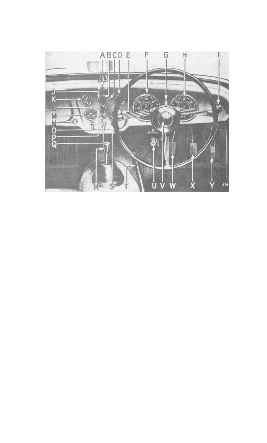
Fig. 2. Instruments, switches and controls.
NOTE :—In left-hand drive cars D changes with K, E with M, and F with H.
A
Scuttle Ventilator Control.
B
Windscreen Wiper Switch.
To open ventilator pull control knob.
Pull knob to operate ; they will only
function when the ignition is switched on. They will return automatically
to the parked position when switched off.
C
Direction Indicator Warning Light.
Will flash when the switch G
is operated and the ignition is switched on.
D
Oil Pressure Gauge.
Indicates pressure of oil at the bearings.
The gauge should read 70 lb./sq. in. minimum when the car is travelling
at normal speeds and the oil is hot.
Low pressure may be registered when the engine is idling or running at
low speeds ; this is quite normal.
E
Water Temperature Gauge.
the cooling water at the thermostat.
The gauge shows the temperature of
Under normal motoring conditions
the water temperature should not exceed 185°F.
F
Speedometer. Registers vehicle's speed and total distance covered,
and is fitted with a trip which is cancelled by pushing up the serrated
knob (situated under the instrument) and turning anti-clockwise.
G
Direction Indicator Switch.
These self-cancelling indicators will
only operate with the ignition switched on, and a warning light (C)
will flash on the dash panel when the switch is operated.
8
Page 10

INSTRUMENTS, SWITCHES AND CONTROLS
H
Tachometer.
Indicates the engine speed in revolutions per minute.
(See page 12).
I
Overdrive Control Switch.
J
Ignition Warning Light.
See page 51.
Glows red when the ignition is switched on
with the engine idling or stopped. It is an indication that current is
being drawn from the battery for the ignition circuit, or other purposes
that are controlled by the ignition switch.
K
Fuel Contents Gauge.
Registers the approximate amount of fuel in
the tank. It operates automatically when the ignition is switched on.
L
Instrument Panel Light Switch.
Turn knob clockwise to switch
on panel lights, further clockwise movement will progressively dim
the illumination.
These lights will only operate when the parking lights are switched on.
M
Ammeter. Indicates the flow of current into or out of the battery.
N
Screen Wash Control
(where fitted).
To operate push the control
knob.
O
Starter Switch.
Press to operate engine starter (see page 11 for full
instructions).
P
Head, Tail and Parking Lamp Switch.
parking lights.
head lights.
Turn slightly clockwise and pull again to switch on the
Press foot operated switch (U) to dip head lights, press
Pull knob to switch on
again for " full on " position, in which position a small red light
appears at the bottom of the speedometer dial.
Q
Ignition Switch.
Insert key and turn clockwise to switch on. Do not
leave the switch " on " when engine is stationary.
R
Gear Change Lever.
Choke Control. See page 11 for full instructions.
S
T
Handbrake.
Pull to operate rear wheel brakes, the handbrake lever can
See Fig. 3 for gear positions.
be retained in any position by pressing the button on the top of the lever.
To release the handbrake lever, first pull it, this will cause the pawl to
be automatically disengaged from the ratchet, the lever is then free to
move forwards and release the brakes.
Headlamp Dipper Switch.
U
Press foot
operated switch to dip headlamps; press again
for high beam position. A small red indicator
light in the speedometer glows when the
headlamps are operating in this position.
V
Horn Button.
Press button in centre of
steering wheel to operate horns.
Fig. 3.
9
Gear lever positions.
SPORTS CAR
Page 11
INSTRUMENTS, SWITCHES AND CONTROLS
W
Clutch Pedal.
Press pedal to disengage drive from engine to gearbox.
Do not rest your foot on the pedal when driving, or hold clutch out to
free wheel.
X
Brake Pedal.
Y
Accelerator Pedal.
Press to operate all wheel brakes hydraulically.
Press to accelerate the vehicle.
Radio Controls.
Seat Adjustment.
See page 51.
The seats are adjustable for " leg length " after operating
the lever which is situated at the side of the seat.
Heater Switch.
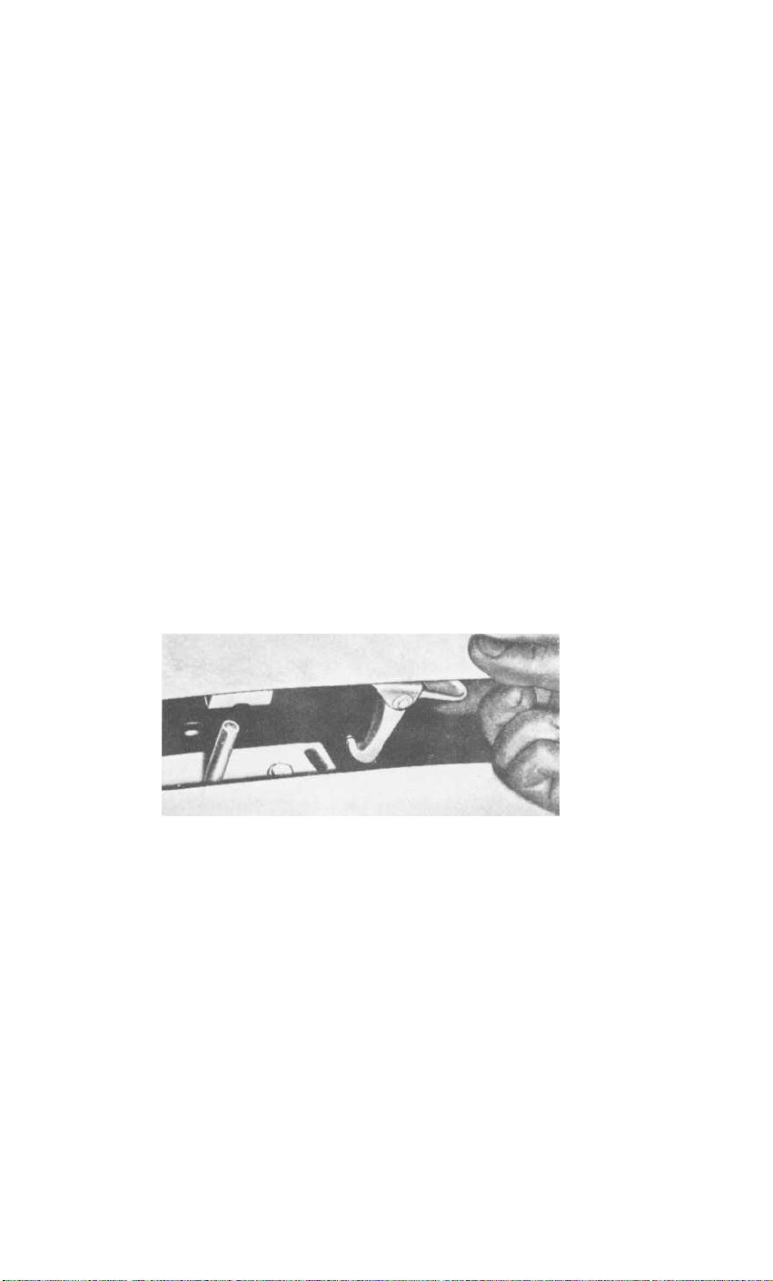
Bonnet Locks.
See page 51.
The fasteners at each side of the bonnet can be released by
turning them anti-clockwise with the special key provided. The safety catch is
situated under the front of the bonnet, in line with the " H " of TRIUMPH
and may be released with the fingers. (Fig. 4).
Fig. 4.
846
Releasing bonnet safety catch.
1
0
Page 12

DRIVING THE CAR
TO START THE ENGINE
IMPORTANT
If the engine does not start when the starter is first operated,
operate the starter again until both starter motor and engine have
come to rest.
Starting when Engine is Cold
Place the gear lever in the neutral position and apply the handbrake. Pull
the carburettor choke control out to its stop, switch on the ignition and
press the starter switch button.
the choke control and allow it to return to the
to lock in this position.
undue hesitation, push the control fully home. If the battery is low use
the starting handle.
the engine, do not keep the choke control out for too long or the sparking
plugs will become wet with petrol.
drying them.
in the carburettor float chambers may have evaporated.
circumstances, operate the hand primer on the fuel pump before the starter
is operated. (See page 37).
When operating the starter in very cold conditions, depress the clutch
pedal to relieve the motor of the considerable drag in the gearbox.
This will avoid damage to the starter pinion.
When the engine has warmed up, turn
half-out
position and turn
When the engine is sufficiently hot to run without
Should difficulty be experienced when starting
This will necessitate removing and
When the car has been left standing for some time, the fuel
do not
Under such
Starting with Engine Warm or Hot
When restarting a hot engine, depress the accelerator pedal to about onethird of its travel before pressing the starter button, the choke control
should not be used.
Warming up
In order to minimise cylinder wear when starting from cold in winter,
the engine should be warmed up quickly. Idle the engine until the oil
circulates and then speed it up. It should not be allowed to idle for long
periods and must not be raced up to high speeds when cold. An engine
speed of approximately 1,500 r.p.m. may be regarded as a desirable
warming up speed.
1
1
SPORTS CAR
Page 13

DRIVING THE CAR
DRIVING
Gear Changing
Use a slow and deliberate movement to change gear, and always move
the gear lever fully home.
of 15 m.p.h.
Reverse gear must not be engaged whilst the car is moving
Do not engage first gear at speeds in excess
forward.
Desirable Speed Limits (Particularly in gears lower than top)
Avoid over-revving, particularly in the lower gears.
not to drive the car continuously at engine speeds above
r.p.m. in any gear.
gears it is permissible to attain
However, whilst accelerating through the
5,000
The driver is advised
4,500
r.p.m. for short periods.
this speed being indicated by a red mark on the tachometer.
New Engines (see "Running Adjustments")
For at least the first 500 miles, the working surfaces of the engine will be
bedding down. The power and performance will improve only if the vehicle is
carefully driven at moderate speeds during the running-in period.
The engine should not be driven at speeds exceeding 3,500 r.p.m. during this
period, and the " running-in " should be progressive. The engine may " rev."
fairly fast so long as it is thoroughly warm and provided it is not
hard.
Do not let the engine pull hard at low speeds, always select a lower gear.
pulling
1
2
Page 14
GENERAL UPKEEP
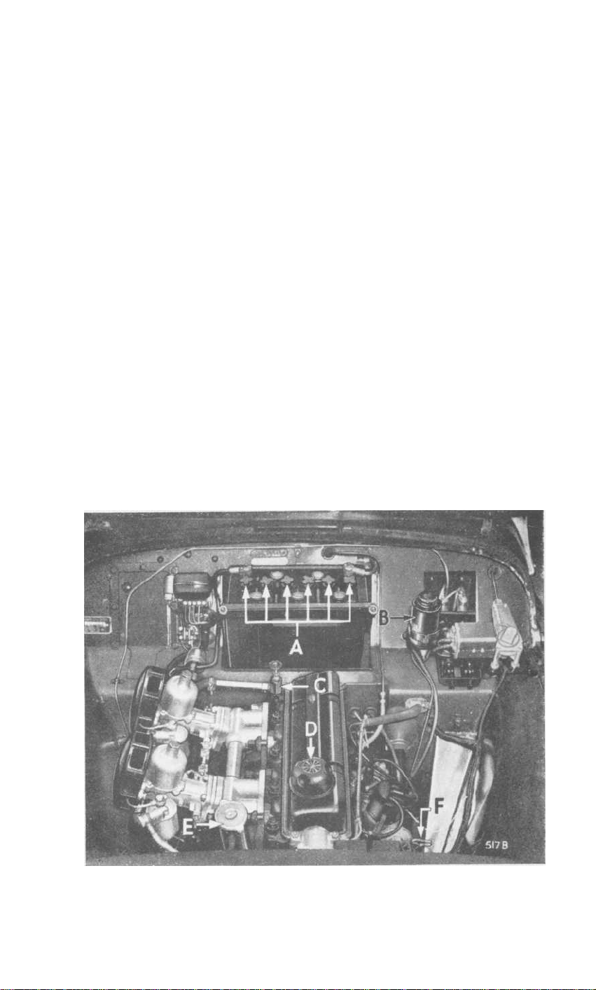
REGULAR INSPECTION
Every 250 miles
necessary.
push fully home before withdrawing for reading. The lower mark on the dip-
stick indicates that 4 pints (Imperial) of oil will be required for topping up.
The regular addition of oil not only maintains the correct level, but also
to keep up the quality of the lubricant.
which must be lifted straight off.
Weekly,
Check :
clean rain water and keep the neck of the filler at least half full of water.
Re-check after the engine has been warmed. The use of hard water results
in a deposit on the inner side of the cooling surfaces, thus reducing efficiency.
Tyre pressures.
the spare tyre inflated to a slightly higher pressure than that recommended,
and reduce its pressure when the tyre is required for use.
Maintain the electrolyte level in the battery
separators.
subsequently attack the surrounding metal panels.
water when replenishing.
to prevent leakage.
electrolyte level.
check the oil level when the engine is cold, and top up if
Withdraw dipstick (F) (Fig. 5) and wipe clean, then insert and
Replenishment is via the cap (D)
The water level in the radiator and replenish if necessary.
The correct pressures are given on page 23.
level
with the top of the
Overfilling will cause electrolyte spillage which will
Use only distilled
Keep the filler plugs (A) (Fig. 5) screwed tight
Never use a naked light when checking the
tends
Use
Keep
Fig.
5.
View under bonnet.
13
SPORTS CAR
Page 15

GENERAL UPKEEP
COOLING SYSTEM
Filling
(see page 13).
Draining
Taps are provided in the bottom tank of the radiator and at the rear of the
cylinder block on the right-hand side. As the cooling system is pressurised
it
will be necessary, when draining, to remove the radiator cap (E) (Fig. 5).
If a heater is fined, ensure that the tap (C) (Fig. 5) is open before draining.
Anti-Freeze Mixtures
Protect the cooling system during frosty weather and reduce corrosion to
a minimum, by use of an inhibited anti-freeze. The use of Smith's "Bluecol",
Duckham's
Anti-freeze,
Esso
Anti-freeze,
Castrol
Anti-freeze,
Shell
" Snowflake " or Mobil Permazone Anti-freeze (inhibited Glycol base
compound) is recommended. The cooling system is fitted with a thermostat
and there is a risk of the radiator block freezing while the engine is running
during the warming up period when the thermostat is shut, even though the
car has been left in a warm garage and water is not frozen at the start of the run.
Provide ample protection for the cooling system against a sudden fall in
temperature down to 0°F. (-18°C.) during frosty weather by using 3 pints
(Imperial) of anti-freeze.
In countries where sub-zero temperatures prevail, consult your Triumph
dealer regarding the quantity of anti-freeze required.
Do not use the same anti-freeze for more than one season since the
inhibitor becomes exhausted and the components in contact with the
cooling water may corrode.
LUBRICATION
This is one of the most important subjects in connection with the upkeep of a
car, and careful attention to the following instructions will be amply repaid by
the results obtained.
For the recommended periods of lubrication, see the lubrication
chart (page 54). The correct lubricants to be used are given on pages
52 and 53
.
1
4
Page 16

GENERAL UPKEEP
Draining
To drain the engine, gearbox and rear axle, remove the plug provided
beneath each unit.
This process is assisted by opening the filler to allow
ingress of air and by draining when the oil is hot, i.e., immediately after
a run.
ENGINE
Only first quality oils are recommended for use in the engine sump. These are
of correct viscosity and character to afford complete lubrication protection
for normal driving.
protection must
Additives which dilute the oil or otherwise impair this
not be used.
Engine Oil Drain Period
The frequency of the drain period should be related to the driving conditions
to which the vehicle is subjected. 3,000 mile intervals are recommended for
average driving conditions as defined below.
This should be reduced for
unfavourable conditions and may be extended for those more favourable.
Favourable
Long distance journeys, with little or no engine idling, on well surfaced
roads, reasonably free from dust.
Average
Medium length journeys on well surfaced roads with a small proportion of
stop/start operation.
Unfavourable
Any of the following:
(a)
Frequent stop/start driving.
Operation during cold weather, especially when appreciable
(b)
engine idling is involved.
(c)
Where much driving is done under dusty conditions.
An upper cylinder lubricant may be used to advantage, during the runningin period of a new engine. The lubricant should be mixed with the fuel in the
proportions given on the container.
Such lubricants
may be used with
advantage throughout the life of the vehicle, particularly during wintry
weather.
1
5
SPORTS CAR
Page 17
GENERAL UPKEEP
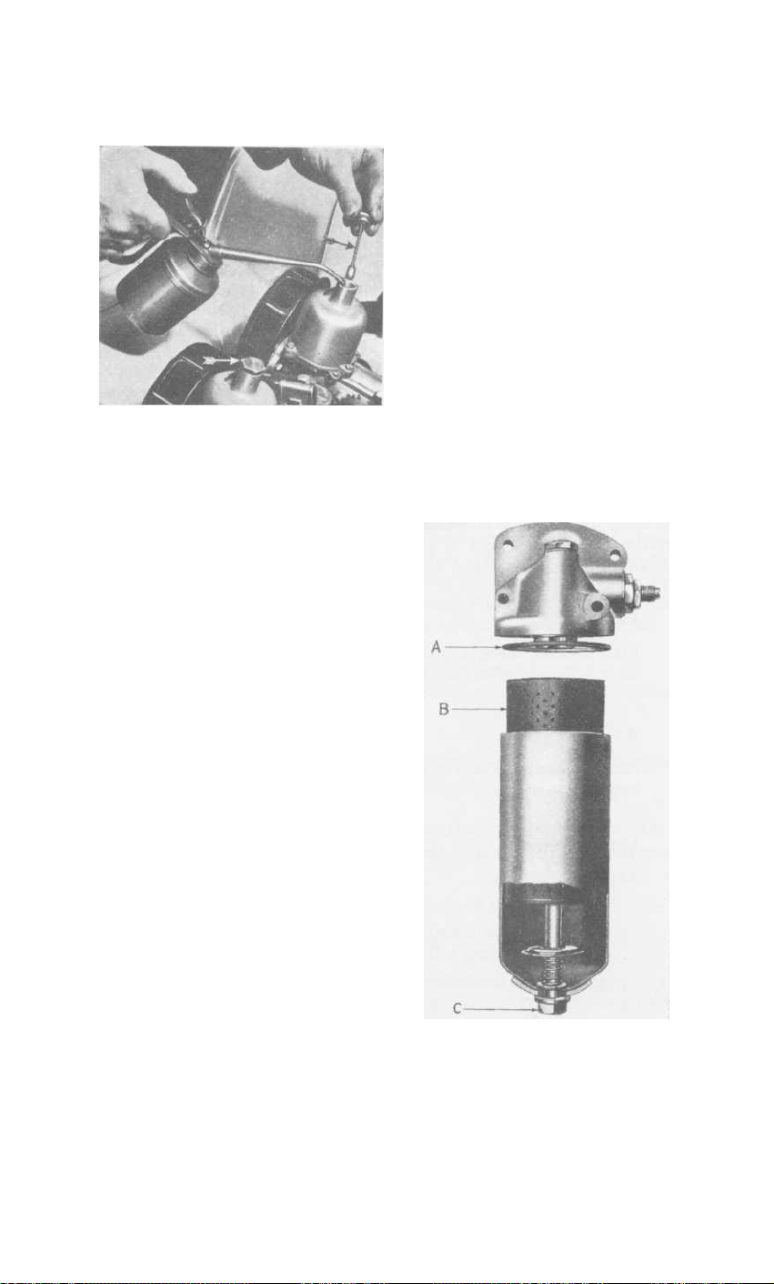
Fig.
6.
Replenishing dashpots.
The Oil Filter
The oil filter is designed to filter the
oil to a very fine degree. It will continue to do this provided that the old
cartridge (B) is removed and a new
replacement cartridge is fitted at periods
not exceeding 6,000 miles. Should this
operation be neglected, the cartridge
will become choked and unfiltered oil
will then be passed to the engine via the
balance valve in the filter. To renew the
cartridge,
unscrew the securing bolt
(C), remove the container and withdraw
the cartridge.
Wash out the container to remove
foreign matter trapped by the filter, and
discard the old container washer (A),
replacing it with a new one each time
the cartridge is renewed.
When reassembling the container, ensure that
the washer is correctly positioned in the
groove in the filter body.
Do not
tighten the bolt (C) more than is necessary to obtain an oil-tight joint.
Drain
the engine oil and refill with fresh oil
before re-starting the engine.
Every
3,000
miles
remove the
dampers (indicated by arrows) and
replenish the dashpots with oil. The
oil level is correct when, utilizing
the damper as a dipstick its threaded
plug is approximately ¼"above the
dashpots,
when resistance is felt.
Apply oil to the throttle linkage but
do not oil the bearings of the transverse rod attached to the bulkhead
as this will seriously deteriorate the
sealing compound.
Fig.
7.
Oil
Filter " full-flow " type.
1
6
Page 18

GENERAL UPKEEP
Ignition Distributor
Every 6,000 miles smear the cam (B) with engine oil.
squeak occurs when the cam is dry.
(Fig. 8)
A pronounced
Withdraw the moulded rotor arm
from the top of the spindle and apply a few drops of thin machine oil
around the edge of the screw (A) to lubricate the cam bearings and
distributor spindle.
At the same time, place a single drop of clean engine
oil on the pivots (C) and (D).
Fig. 8.
Ignition distributor.
Water Pump
One nipple is provided (see arrow Fig. 9) to which the grease gun should
be applied every 6,000 miles.
Give five strokes only with the gun.
Fig. 9.
Water pump.
Grease nipple arrowed.
Generator
After completing 20,000—30,000 miles, remove the generator for cleaning,
adjustment and repacking the front bearing with grease.
This should
be done preferably by the nearest Triumph or Lucas Service Depot.
Every 6,000 miles pour a few drops of engine oil through the hole in the
centre of the rear end cap.
1
7
SPORTS CAR
Page 19

GENERAL UPKEEP
Air Cleaners
Every 6,000 miles, remove the air cleaners and wash them in petrol,
particularly the gauzes, which must then be soaked in oil and allowed
to drain before finally wiping them over and refitting. It is very important
when refitting the air cleaners that the holes immediately above the
setscrew holes in the carburettor are aligned with similarly positioned
holes in the cleaner.
Oil Filler Cap
Every 6,000 miles remove and rinse the cap in fuel, dry off and re-fit.
GEARBOX
Every 6,000 miles check, and if necessary, top up the oil level via the plug (1).
Every 12,000 miles drain the gearbox by removing the plugs (1) and (2).
Replace the plug (2), replenish via plug hole (1) and finally tighten both plugs.
If an overdrive is fitted, see page 51.
Fig. 10.Gearbox oil filler level plug (1)
and drain plug (2).
REAR AXLE
To ensure efficient operation and long life of the hypoid bevel gears, use only
those special lubricants recommended
pages 52 and 53. Drain the axle
on
and replenish with new " Hypoid " oil every 6,000 miles.
1
8
Page 20

GENERAL UPKEEP
Check the oil level during this period, especially after the first 1,000 miles,
and replenish if necessary to level with bottom of the threads in the filler
orifice.
Should a top-up be necessary, investigate the cause of oil loss.
filler plug fitted to the rear axle cover is accessible from underneath the car
(see arrow A, Fig. 11). Clean away mud before unscrewing the filler plug to
avoid grit falling into the axle.
BRAKE AND CLUTCH OPERATION
The hydraulic fluid for clutch and brake operation is contained in a single
reservoir
which has an inner and outer chamber.
The inner chamber is
connected to the clutch withdrawal mechanism and the outer chamber to the
brakes.
Check the fluid level every 1,000 miles.
with the top of the inner chamber.
use only the special fluid recommended.
The fluid must be maintained level
When filling or topping up the reservoir,
Any other fluid may be dangerous.
Clutch Shaft Bearings
Apply the grease gun to the clutch shaft bearing grease nipples (one at each
side of the clutch housing) every 6,000 miles.
One shot is sufficient.
nipples are accessible from underneath the car. (See arrow (3), Fig 32, page
38).
The
The
Clutch and Brake Pedal Bearings
Apply the oil can to the various pivots, etc., of the pedal linkages, both
under the bonnet and in the driving compartment.
Fig. II.Rear axle oil filler and handbrake compensator.
1
9
SPORTS CAR
Page 21

GENERAL UPKEEP
Handbrake Cable Conduit
Every 6,000 miles, apply the grease gun to a grease nipple fitted in the conduit,
as shown on the lubrication chart.
During the winter months it is important to keep the cable regularly lubricated.
This will prevent the entry of water and the possibility of freezing which would
lock the brake cable.
When lubricating the cable, pump the gun until grease exudes from the end of
the conduit.
Handbrake Compensator.
Lubricate the handbrake compensator via the two grease nipples (B) (Fig. 11)
every 6,000 miles.
ROAD WHEEL HUBS
Front
Every 12,000 miles (if the vehicle is used for competition work every 6,000
miles) repack the hubs with grease. This involves removing the hubs and
washing the bearings to remove all traces of the old grease before packing
the rollers and races with new grease.
Do not disturb the pipe unions but
unbolt and move the complete caliper to allow the hub and disc to be
removed.
Take care not to lose shims which may be fitted between the
caliper and the vertical
link.
When replacing, ensure
that the inner race is tight
against
its
shoulder.
Tighten the hub nut until
resistance is felt to hub
rotation, then slacken off
the nut by one half flat
and insert the split pin
through one of the two
holes provided.
Rear
Every 6,000 miles, give
five strokes of the grease
gun to a nipple (2) (Fig.
12), situated behind the
rear
backing plate and
facing downwards.
Fig. 12.Brake Backing plate Details.
20
Page 22

GENERAL UPKEEP
FRONT SUSPENSION AND STEERING
Nipples are provided for lubricating the steering swivels (A), outer tie rod,
ball joints, outer bushes of. the lower wish-bones (B) (Fig. 13), and the
steering slave drop arm pivot.
drop arms as they contain rubber.
Do not lubricate the joints attached to the
Lubricate the inner nylon wish-bone
bushes with oil occasionally. A pronounced squeak develops when these bushes
become dry.
When greasing the lower suspension swivels it is an advantage
to jack up under the road spring pan until the front wheel is free of the
ground.
This allows grease to cover the thrust faces.
Grease these points
every 1,000 miles.
After greasing the steering swivels, wipe away all surplus grease.
This will
prevent it from contaminating the disc brakes.
Fig. 13.
Front suspension lubrication.
2
1
SPORTS CAR
Page 23

GENERAL UPKEEP
Every 6,000
miles,
lubricate the steering
box after removing
the rubber plug
situated on the steer-
ing column and top
up with oil to the
level of the orifice.
Fig.
14.
Steering box filler/level plug (arrowed).
REAR ROAD SPRINGS
Paint over the spring blades with old rear axle or engine oil, particularly
around the blade tips and clips. Avoid lubricating the rubber bushes which
are fitted in all the rear spring eyes.
HYDRAULIC DAMPERS
The front telescopic dampers do not require " topping up."
Top-up the rear dampers with
to the level of the bottom of the plug hole (arrowed Fig. 35), every
son)
12,000 miles.
When topping up, it is essential that dirt is prevented from
Armstrong Shock Absorber Fluid (Crim-
finding its way into the interior. Faulty dampers can only be serviced by the
manufacturers.
PROPELLER SHAFT (Fig. 15)
Every 1,000 miles, lubricate the
needle roller bearings and splines.
Supply the nipple (B) at each end
of the shaft with oil for the bearings,
and the nipple (A) with grease for
Fig. 15
Propeller shaft lubrication points.
.
the splines.
HINGES, CONTROLS, DOOR LOCKS, ETC.
Give occasional attention with an oil can to the bonnet catches, hinges and
several small control joints.
Door locks should receive a drop of oil every
month to ensure easy operation and to prevent corrosion. Attention given to
the connections on the handbrake and ratchet mechanism, etc., will enable the
controls to work freely and prevent unnecessary wear.
2 2
Page 24

TYRE PRESSURES
OPERATING CONDITIONS
Normal motoring with sustained
speeds limited to 85 m.p.h.
Fast motoring on Motorways and
similar
speeds up to 100 m.p.h.
High speed tuning with speeds
regularly in excess of 100 m.p.h.
roads
with
sustained
Goodyear Allweather
Rib
and
Dunlop Gold Seal
5.50/5.90-15 5.50/5.90-15 5.50/5.90-15
Lbs. per sq. in. Lbs. per sq. in.
Front
...
...
20
26 30 20 24
Not
recommended
Rear
24
Goodyear Allweather
Rib Nylon
and
Dunlop Gold Seal
Nylon
Front
20
26
Rear
24
30
Goodyear Motorway
Special
and
Dunlop Road Speed
R.S.5
Lbs. per sq. in.
Front
20
20
20 24 24 32
Rear
24
24
Goodyear D.F.S.
(165—380)
Michelin
(165/15X)
(165/15X)
Lbs. per sq. in.
Front
24
24 32
and
Rear
32
Page 25

GENERAL UPKEEP
TYRES
The maintenance of correct tyre pressures is important to the life of the tyres
and behaviour of the steering and suspension.
Examine the tyres occasionally for flints or other road matter which may have
become embedded in the tread. By using fuel sparingly, clean off any oil which
may have got on the tyres. Driving into or over sharp edged kerbs is liable
to fracture the walls of the tyres and should be avoided where possible.
Changing Position of Tyres
Every 3,000 miles interchange the front tyres with rear tyres.
Diagonal
interchanging between left front and right rear and between right front and
left rear provides the most satisfactory first change. This reverses the direction
of rotation and keeps the wear of the tyres even and uniform.
FRONT WHEEL ALIGNMENT
Alignment of the front wheels is most important in its effect on tyre wear
and good steering. Excessive toe-in will lead to severe tyre wear, particularly
on the " kerb side " front tyre.
The front wheel alignment should be parallel to ⅛
"
toe-in when the following
tyres are fitted :
Dunlop Gold Seal, Dunlop Gold Seal Nylon, Dunlop Road Speed, Goodyear
Allweather Rib, Goodyear Allweather Nylon, Motorway Special.
When Goodyear D.F.S. and Michelin X tyres are fitted the front wheel align-
ment should be parallel to 1/16
" toe-in.
To Check and Adjust Wheel Alignment
If adjustment is found necessary it should be carried out equally on the
two outer tie-rods.
When adjustment is complete ensure that the ball
joints are in the centre of " swing " before securely tightening the tierod locking nuts.
THE JACK
A screw-jack is provided which is adapted to lift either side of the car as required.
Apply the handbrake, or chock the wheels which will remain on the ground,
before operating the jack.
To fit the jack in position (Fig. 16), turn up the
carpet and remove the rubber plug situated just in front of the seat. Engage
the lower lip of the jack boss with the bottom edge of the rectangular hole,
then swing the jack into a vertical position and lift, make sure that it is right
2 4
Page 26

GENERAL UPKEEP
home in its socket
before operating the
jack handle.
If a jack is used under
the rear axle case,
ensure that the jack
pad does not touch
the rear cover plate
when lifting, otherwise there is a risk
of damage and consequent oil leakage.
Fig.
16.
Jacking the car.
WHEEL ATTACHMENT
Before removing a road wheel ensure that the wheel is clear of the ground and
the vehicle is safely supported.
Pressed Steel Wheels
After removing the nave plate (Fig. 17), the wheel nuts (R.H. thread) can
be detached with the wheel brace (2) (Fig. 20).
Wire Wheels
A copper faced hammer is provided with cars fitted with wire (" knock on ")
wheels to facilitate hub cap removal. Turn the huh caps on the right-hand side
of the car clockwise and the hub caps on the left-hand side anti-clockwise to
remove.
Fig. 17.
Removing nave plate.
2 5
Fig. i8.
Removing L.H. front hub
SPORTS
cap.
CAR
Page 27

TOOLS
Fig.
19.
Tools stowed in spare wheel compartment.
The jack and wheel brace are situated in the spare wheel compartment
(Fig. 19).
luggage compartment. If the vehicle has wire wheels, then the wheel brace
(2), combination tool (5) (Fig 20), are omitted from the tool kit and a
screwdriver, tommy bar and copper-faced hammer are included.
The remaining tools are placed in the tool roll and stowed in the
1.
Jack handle.
2.
Wheel brace.
3.
Starting handle. (Special Order)
4.
Jack.
5.
Combination tool
(Screwdriver, tommy bar,
and nave plate remover).
6. Valve core remover/replacer.
7.
Pliers.
8.
Spanner.
9.
Spanner.
Fig.
20.
2 6
Tools.
Coach key.
10.
11.
Headlamp rim remover.
12.
Spanner. (⅝" x ¾" A.F.)
13.
Tool roll.
Adjustable spanner.
14.
15.
Box spanner.
16.
Box spanner.
17.
Grease gun.
18.
Feeler gauges.
19.
Screwdriver and feeler gauges
(distributor points).
Page 28

BODYWORK
Dust may be removed from the exterior by using a soft cloth only, but if it has
been wet at any time it is advisable to use a sponge and water. Always use
water when removing mud and when the car is clean finally wipe over with
an almost dry chamois leather.
of the paintwork over an indefinite period and it may become necessary to
use a cleaner to remove all grease and dirt. It is advisable to acquire the
cleaner from a reputable dealer who will be able to supply you with the best
cleaner to suit the particular paintwork of your car.
may be used to advantage.
Special cleaners are available for removing traffic film and tar.
plated parts need cleaning with soap and water, and wax polishing is beneficial.
due to neglect, the plate becomes spotted, it may be necessary to use a
If,
chromium plate cleaner.
Dust interior of the car occasionally and brush the carpet with a stiff brush.
The upholstery may be cleaned by the application of a little soap and damp
cloth, followed by a final wipe down with an almost dry sponge or chamois
leather.
Never use detergents as these may affect the surface of the material.
When a vacuum cleaner is available it can be used with advantage to help
clean the interior.
Washing alone will not keep up the brilliance
A non-abrasive polish
Chromium
DOOR ADJUSTMENT
The doors are provided with special locks which, when correctly adjusted,
prevent any movement of the closed door.
Only the striking plate requires
repositioning when adjustment becomes necessary.
This adjustment is best carried out by a coach fitter.
SOFT TOP MAINTENANCE
The top should be washed with the same regularity as the rest of the car.
With the exception of warm water and non-caustic soap, the use of all cleansing
agents, detergents and wax polishes must be avoided.
Never leave the top folded when it is wet or damp.
Occasionally oil the hinge points of the hood sticks (support frame) with
engine oil, work the moving parts, and wipe all surplus oil away.
Removal and Stowage of Side Screens
The key provided for opening the bonnet also releases the special catches
which secure the side screens to the door panel.
Release the fastener securing the short strap on the centre of the screen to the
door.
Turn the key in an anti-clockwise direction to release the catches and lift the
screen clear of the door.
The side screens may be completely removed from
the car or stowed away in the luggage locker.
2 7
SPORTS CAR
Page 29

BODYWORK
A.
Soft top rear attachment points.
B.
Hood support sticks raised.
C.
Soft top front attachment points.
Fig. 21.Soft top details.
D.
E.
F.
28
Hood support sticks lowered.
Hood support stick cover.
Utilizing key 10 (Fig. 20) to
detach side screens.
Page 30

BODYWORK
Fig.
22.
"
Tenax " soft top fasteners.
Removal and Stowage of Soft Top
Two types of fasteners are used.
They are " Lift the Dot " and " Tenax ".
When fitting either type it is only necessary to push fasteners over the securing
stud as shown in Fig. 22.
With the " Tenax " type (as illustrated) do not press
or pull the small knob before engagement as there will be risk of damage to the
inner prongs.
After fitting, the knob may be pressed to ensure correct engagement.
To
remove the fasteners, either pull the small knob, or in the case of the " Lift
the Dot ", do as its title suggests, lift the outer edge.
When removing the fasteners from the screen, relieve the tension on the
fasteners by applying a slight hand pressure, in the forward direction, to the
corner of the soft top where it passes over its supports.
Release the fasteners at the top of the windscreen, allow the material to hang
down on the seats and release the fasteners from rear waist moulding.
Fold the top material taking care not to crease the rear windows and stow
it away in the locker.
Press the hood sticks downwards into the back of the car. The lower hinge
must be pushed below centre and then forward to enable the sticks to fold
down into line with the rear of the body.
Fit and secure the hood stick cover utilising the pegs on the waist line and the
rear of the seats.
2 9
SPORTS CAR
Page 31

BODYWORK
Fig. 23.
A.
Hard top fitted.
B. Tonneau cover fitted.
Hard top and tonneau cover.
C.
Front hard top fixings (3 off)
D.
Rear hard top fixings (5 off)
30
Page 32

RUNNING ADJUSTMENTS
Various adjustments are necessary from time to time in order to maintain the
mechanism in good running order.
carrying out these adjustments since this is dependent upon the manner in
which the vehicle is used.
The most important adjustments and the re-
commended intervals between, are as follows.
Cylinder Head Nuts
After the first 1,000 miles check the cylinder head nuts for tightness
whilst the engine is hot, in the order shown on Fig. 24.
No definite period can be stated for
ENGINE
Fig.
24.
Order of tightening cylinder head nuts.
Valve-Rocker Clearances(measured cold)
Set the inlet and exhaust valve-rocker clearances at 0.010". These
settings are correct for both normal and high speed running.
Ignition Timing
4° before Top Dead Centre (crankshaft angle).
Use only Premium grade fuels of 95 octane or higher and so long as the
engine is free from carbon, it will not pink. A substantial carbon build-up
may cause " pinking ". This will necessitate retarding the ignition slightly
so that " pinking " is just audible when pulling hard when the engine
speed is in excess of 1,500 r.p.m.
To advance ignition, rotate the knurled screw on the distributor. Each
division on the distributor vernier scale represents 2° on the distributor,
i.e.,4° on the crankshaft.
The firing order is 1, 3, 4, 2.
3
1
SPORTS CAR
Page 33

RUNNING ADJUSTMENTS
Fig. 25.
Ignition leads.
To obtain TDC rotate the
crankshaft until the inlet
valve of No. 1 cylinder is
open then slowly turn the
crankshaft until the small
hole in the crankshaft belt
pulley
ti
aligns
with
ming cover pointer (Fig.
the
26).
Fig. 26.
TDCindication.
Sparking Plugs
It is important that the correct type of sparking plugs are fitted when making
replacements, and that the electrode gaps are set to 0.025" (0.65 mm.).
For normal road work use
For high-speed touring use
For competition work use
...
LODGE, CNY
...
LODGE, HN
...
LODGE, 2HN
In certain cases when a lower compression ratio is used due to the nonavailability of high octane fuel, it may be necessary to use softer plugs,
Lodge CN.
Incorrect gap settings may cause misfiring or erratic slow running.
Clean
and adjust the sparking plugs at 3,000 miles (5,000 km.). Renew all sparking
plugs at 12,000 miles (20,000 km.).
32
i.e.
,
Page 34

RUNNING ADJUSTMENTS
TWIN S.U. CARBURETTORS (Type H6)
Tuning
Multi-carburettor installations cannot be successfully tuned unless the
general engine conditions (such items as tappet clearance compressions) and the
ignition system are in a satisfactory state.
With regard to the carburettors
themselves the cleanliness of the suction piston units, the position of the
needles, the jet centring and oil level in dampers, etc., should be checked.
With the aforementioned in a satisfactory state, refer to Fig. 27 and proceed as
follows :-
Remove air cleaners from carburettors.
1.
Slacken clamping bolt on throttle connecting rod (4) so that throttles may
2.
be set independently.
Ensure that the throttle adjusting screws (3) are
holding the throttles open and that the jet adjusting nuts are not screwed
right up.
Ensure that the screw (2) is clear of its abutment and that the choke
3.
Disconnect the mixture control rod (5).
cable is not likely to hamper jet adjustment. If necessary, disconnect
choke cable.
With the engine at normal running temperature and the idling speed
4.
approximately 500 r.p.m., check the hiss of air at carburettor intakes
with a piece of tubing approx. ⅜" (9.5 mm.) bore.
Carburettors.
3.
4.
Mixture control rod.
Throttle adjusting screws.
Throttle connecting rod.
1.
Air cleaners.
2.
Choke control screw.
Fig. 27.
5.
3 3
SPORTS CAR
Page 35

RUNNING ADJUSTMENTS
5.
With a downwards pressure on the throttle adjusting screw (3), adjust
the appropriate screw until the level of hiss is similar at both carburettor
intakes and the idling speed approximately 500 r.p.m.
To reduce hiss at carburettor intake, UNSCREW the adjusting screw.
6.
When level of hiss is similar, stop engine and with a downward pressure
on the rear throttle arm, tighten the throttle spindle clamping bolt and
re-check hiss.
7.
Start the engine and allow it to idle at approximately 500 r.p.m.
Check mixture on each carburettor in turn by lifting the piston approxi-
8.
mately ⅛"(3 mm.) with a pen-knife blade or lifting pin (3) (Fig. 28).
9.
If when the piston is lifted the engine speed increases the mixture is too
rich and the nut (7) should be screwed up one flat. If the engine speed
decreases unscrew nut (7) one flat.
10.
Continue adjustment on
no increase, or a very slight increase followed by a fall in engine speed is
noticed.
regular and even.
11.
Attach choke cable (if previously disconnected).
control rod, ensuring that the jet levers are pressed forward and the
control rod is adjusted correctly for length.
12.
Replace air cleaners.
13.
Re-check idling speed and mixture.
The mixture is then satisfactory and the exhaust note should be
each carburettor until when the piston is lifted,
Reconnect the mixture
Jet Centralizing
When the suction piston is lifted by hand (engine not running), it should fall
freely and hit the jet bridge with a soft metallic click—that is, with the jet
adjusting nut (7) in its topmost position.
If this click is not audible, but is so when the test is repeated with the jet in
the fully lowered position, then the jet unit requires re-centralising on the
needle, as described below.
may be helpful to understand that the complete jet unit, clamped in
It
position by the gland nut (4), is held in a clearance bore that permits a limited
amount of radial float, prior to being locked.
slackened, the jet assembly can be moved until it is concentric with the needle,
thus enabling the piston to move freely to its lower position.
The procedure for re-centralising is as follows :
1. Remove air cleaners.
2.
Remove return spring (6), pivot pins (8), and swing linkage to one side
(disconnect the choke cable if necessary).
3.
Withdraw jet (9), unscrew adjusting nut (7) and remove spring (5).
4.
Remove damper assembly (2).
Replace adjusting nut (7), screwing it to its upper position.
5.
6.
Slacken gland nut (4) and insert jet (9).
(Fig. 28)
Therefore, if the gland nut is
3
4
Page 36

RUNNING ADJUSTMENTS
Air cleaners.
1.
2.
Dampers.
3.
Piston lifting pin.
4.
Gland nut.
5.
Jet spring.
Fig.
28.
Carburettors.
Mixture control rod.
11.
6.
Return spring.
7.
Jet adjusting nuts.
8.
Pivot pins.
9.
Jets.
10.
Choke cable.
Whilst holding the jet (9) in its upper position, move the jet assembly
7.
laterally
gland nut (4).
until the jet is concentric with the needle, then tighten
This condition has been achieved when the piston
assembly will fall freely and evenly, hitting the jet bridge with a soft
metallic click.
Withdraw the jet and re-check to see if there is any difference in the
sound of the impact, if there is and the second test produces a sharper
mpact sound, the centralising operation will have to be repeated until
i
successful.
In the occasional obstinate case the jet adjusting nut (7) as well as the
8.
spring (5) should be temporarily removed to enable the jet to reach a
higher position and make the centralising effect more positive. Replace
the spring (5), adjusting nut (7), jet (9), pivot pins (8) and
secure with new split pins after the successful conclusion of the operation.
Before replacing the air cleaners, replenish the dampers and tune the
carburettors, see pages 16 and 33.
35
SPORTS CAR
Page 37

RUNNING ADJUSTMENTS
Float Chamber Fuel Level
The level of the fuel in the float chamber is adjusted by setting the fork
lever in the float chamber lid. It is suggested that the following procedure for
its adjustment is adopted,
1.
Disconnect the fuel feed pipe from the float chamber lid, then remove the
lid securing nut, washers and overflow pipe.
2.
Lift the lid off the float chamber.
3.
The set of the forked lever is correct, when, with the lid of the float
chamber inverted and the shank of the forked lever resting on the needle
of the delivery valve, it is possible to pass a 7/16"(11
mm.) diameter rod,
see " A " Fig. 29, between the inside radius of the forked lever and the
flange of the lower face of the float chamber lid.
If the forked lever fails to conform within 1/32"(.8
mm.) of the check
figure, it must be carefully bent, at the start of the fork section, taking
care to keep both prongs of the fork level with each other.
must be emphasised that it is not advisable to alter the fuel level
It
unless there is trouble with flooding. Although too high a level can cause
slow flooding, particularly when a car is left ticking over on a steep drive,
it should be remembered that flooding can also be caused by grit in the
fuel jamming open the needle valve, undue friction in the float mechanism,
excessive engine vibration, or a porous float.
Re-assemble the carburettor and connect fuel pipe.
4.
Fig.
29.
Adjusting the fuel level.
Cleaning Suction Chamber and Piston
This should be done at approximate intervals of twelve months.
After
detaching the unit, clean the main inside bore of the suction chamber, and the
two outside diameters of the piston with a rag moistened in petrol and then
re-assemble in a dry and clean condition with a few spots of thin oil on the
piston rod only.
Do not forget to replenish the damper reservoir after this
operation.
3 6
Page 38

RUNNING ADJUSTMENTS
Needles
The correct needle for normal and competition work is S.M.
When the
carburettors are fitted with oil bath air cleaners use CIW needles.
The needle should be fitted with its shoulder flush with the under face of the
piston (Fig. 30). It is retained in position with a screw.
FUEL PUMP
The mechanically operated fuel pump, mounted on the left-hand side of
the crankcase, provides a constant pressure of fuel to the carburettors.
hand primer is fitted, which can be used to pump fuel to the carburettors
if the float chambers are not already full, under which condition a slight
pumping resistance is felt before the lever reaches its stop.
This resistance
ceases when the chambers are full.
A
Fig.
31.
3 7
Fuel pump.
SPORTS CAR
Page 39

RUNNING ADJUSTMENTS
The glass bowl acts as a sediment chamber for the petrol passing to the pump.
This foreign matter collects on the underside of the gauze and, being washed
off by petrol, sinks to the bottom of the bowl. To remove the sediment, detach
the bowl by unscrewing the nut (arrowed Fig. 31) at its base and wash out
the bowl with the fuel that will be in it.
the nut sufficiently to ensure a fuel-tight joint.
When refitting the bowl, tighten
Over-tightening
may result
in damage.
CLUTCH
The clutch reservoir is the same as that used for the brake system. (See (B)
Fig 5, page 13).
There is a partition in the container which separates the two systems and
ensures that any defect in one system does not affect the other.
Adjustment of the mechanism is checked at the connecting rod between the
operating cylinder and the shaft operating lever end (see Fig. 32). The correct
setting is when there is 0.1" end float of the rod between operating cylinder
and lever, in the " foot off " condition.
total
movement of the operating lever by hand and if different from the
To achieve this setting, measure the
specified amount release the locknut (2, Fig. 32) and adjust the length of the
connecting rod to the correct figure.
The adjustable connection between
pedal and master cylinder is set on initial assembly and MUST NOT be altered.
If a pipe has been disconnected, it will be necessary to bleed the system.
A bleeder nipple is shown by the arrow (1, Fig. 32). For instruction on bleeding
the system see page 40.
Fig.
32.
Clutch slave cylinder.
3
8
Page 40

RUNNING ADJUSTMENTS
BRAKES
The pedal operates the brakes on all four wheels hydraulically, whilst the
handbrake operates the brakes on the rear wheels by means of cables.
See page 19 for checking level of fluid in reservoir. If the level of fluid is
particularly low, this indicates that a leak has developed in the system.
This
must be traced and rectified without delay.
It
must be remembered that the presence of oil, grease or similar foreign
matter on a drum brake shoe will seriously affect retarding effect of that
particular brake, in spite of the fact that it is being applied with the same
force as the others. In such cases thoroughly clean the brake drum with
fuel and fit new replacement shoes. Cleaning the brake shoes is not satisfactory.
Do not re-line the shoes but fit genuine Girling replacement shoes. These have
the right type of lining machined to the correct radii.
Should the shoes be removed, exercise care when replacing them to ensure
that the pull-off springs are located behind the shoes and hooked through the
correct holes, as shown.
Fig. 33.
R.H. front disc brake
assembly.
Fig.
34.
R.H. rear brake assembly.
Front Brakes
The disc brakes, fitted to the front axles, are self-adjusting and should
only need replacing when the shoe pads are reduced to approximately
⅛"
thickness.
Rear Brakes
The rear brakes are provided with a small adjuster (3) Fig. 12 which is
positioned on the backing plate, above the axle case, and easily accessible
with the road wheel removed. To correctly adjust the shoes, turn the
adjuster clockwise until the shoes are hard against the drum, then
slacken off adjuster by one notch.
If the drum is then not free to
rotate slacken adjuster still further.
3
9
SPORTS CAR
Page 41

RUNNING ADJUSTMENTS
Handbrake Adjustment
Adjustment of the rear brake shoes as previously described automatically
readjusts the handbrake mechanism.
leaving the works, and only maladjustment will result from tampering with
the mechanism.
Bleeding the Brake and Clutch Hydraulic System
If a pipe joint is uncoupled, the wheel cylinder cups or clutch operating cylinder are inspected or replaced, the system must be bled in order to expel any
air which may have been admitted.
Air is compressible, and its presence in the system will affect the working
of the brakes and clutch.
Whilst the majority of owners will prefer to have these operations carried
out by a Triumph Agent, for the benefit of those desiring to carry out
their own running adjustments, the procedure is as follows :
Clean the bleeder nipple and fit a piece of rubber tube over it,
1.
allowing the tube to hang in a clean container partially filled with
fluid, so that the end of the pipe is below the level of the fluid.
The cables are correctly set before
2.
Unscrew the bleeder nipple one complete turn.
bleeder nipple to each wheel and one nipple on the clutch operating
cylinder.
3.
The fluid reservoir should be filled before commencing the bleeding
operation, and must be kept at least half-filled during the whole
operation, otherwise air will be drawn into the system via the
master cylinder.
system for maintaining the level.
filler cap before removing it.
Depress the pedal quickly and allow it to return without assistance.
4.
Repeat this pumping operation with a slight pause between each
depression of the pedal. Observe the flow of fluid being discharged
into the glass jar and when all air bubbles cease to appear, hold the
pedal firmly down and securely tighten the bleeder nipple.
NOTE.—Depending upon the position at which a pipe joint in the brake
system has been uncoupled, it will be necessary to bleed the system at
either both front or both rear wheels. If the pipe was uncoupled at the
master cylinder, then the system must be bled at all four wheels.
Do not use fluid that has been expelled from the
Always clean the area around the
4
0
There is only one
Page 42

RUNNING ADJUSTMENTS
PROPELLER SHAFT
If the propeller shaft has been taken apart it is essential to ensure that the arrows
on the universal joint and propeller shaft are aligned during re-assembly (see
Fig. 15, page 22).
HYDRAULIC DAMPERS
The front telescopic dampers cannot be adjusted or topped-up. If they
have been removed, hold them the right way up and pump the pistons to each
end of the stroke before refitting them.
Check the level of the fluid in the rear dampers and replenish if necessary,
then pump the pistons to each end of the stroke. This pumping action dispels
any air which may have entered the chambers. After this operation, keep the
dampers the right way up until they are fitted into place.
Fig. 35.
L.H. rear damper.
LOOSE BOLTS AND NUTS
All the vital nuts are locked in position by split pins, locking wire, or by an
additional locknut or lock washer.
It is, however, desirable that the car be
examined every 6,000 miles and a check made for nuts which may require
attention.
The wheel nuts can periodically be checked by the owner
himself and occasionally removed, oiled and refitted.
The general examination of the chassis is a mechanic's job.
4
1
SPORTS CAR
Page 43

ELECTRICAL SYSTEM
A 12 volt earth return lighting and starting set is fitted.
be disconnected from the battery terminal before removing any
electrical unit, otherwise there is risk of a serious " short ".
A list of the maker's numbers and descriptions of electrical equipment will
be found on page 50.
IGNITION
Failure of the red warning light will not affect the ignition system, but the
bulb should be replaced at the earliest opportunity.
should be examined occasionally and if they are perished or worn through,
replace with the correct ignition cable, which should be obtained only from
your dealer, and should be of the correct length.
The moulded distributor cover should be removed occasionally and wiped all
over with a soft cloth. See that the carbon brush on the inside of the moulding
works freely in its holder.
contact breaker points.
commended on page 7. The distributor has the radio suppressor built into
the distributor head.
the ignition and coil leads a suppressor will not be apparent.
placement or spare distributor head is required, take care to ensure
that it is of the correct type with the long carbon pick-up, which is,
in fact, the suppressor.
Clean away any trace of dirt or dust around the
The points should be adjusted to the setting re-
This, of course, means that on outward inspection of
One cable should
The high tension leads
If a re-
THE BATTERY
Keep the terminals clean and well covered with petroleum jelly. If they are
corroded, scrape them clean, assemble and cover with petroleum jelly.
away all dirt and moisture from the top of the battery, and make sure that
the connections are clean.
battery as this may result in the case becoming cracked.
The generator operates in conjunction with the regulator unit which is housed
alongside the cut-out in the control box.
the generator charges the battery at the rate best suited to its condition.
automatically provides a large charging current for a discharged battery
Do not over-tighten the nyloc nuts securing the
THE GENERATOR
The regulator unit ensures that
4
2
Wipe
It
Page 44

ELECTRICAL SYSTEM
and a low trickle charge for a battery in the fully charged state.
The cut-
out, operated by generator voltage, prevents discharge of the battery through
the generator when the generator is not charging, in which condition the
ignition warning light will be glowing.
Belt Tightness
It is important that the belt is sufficiently tight to drive the generator,
but not too tight as would put undue load on the generator and water pump
bearings.
The correct tension is achieved when the belt can be pressed
inwards ½"—¾" on the longest run, i.e., from the dynamo pulley to
the crankshaft pulley.
It is essential after adjustment has been made
to securely tighten the attachment nuts and bolts (2), (3), (4) and
Fig. 36.
(5),
Fig. 36.
Generator.
THE STARTER MOTOR
Cleaning and Lubrication
The starter brush gear and commutator will not normally require attention.
After
48,000
miles however, it is advisable to have the unit serviced at
a Triumph or Lucas Service Depot.
3
4
SPORTS CAR
Page 45

ELECTRICAL SYSTEM
Should the starter pinion become jammed in mesh with the flywheel, then
may be released by turning the crankshaft with the starting handle, or by
it
selecting top gear and rocking the car backwards and forwards, or by removing
the metal cap on the end of the starter motor and turning the end of the shaft
with a spanner, Fig. 37.
Fig. 37.
Releasing pinion from flywheel.
CONTROL BOX
The control box, mounted on the bulkhead, houses the voltage regulator and
cut-out.
These units are carefully and accurately set before leaving the works
and must not be tampered with.
FUSES
The fuse carrier is located forward of the control box and houses two operating
and two spare fuses. The L.H. fuse (35 amp.) protects the horn, while the other
fuse (35 amp.) protects those items which can only operate when the ignition
switched on, i.e., direction indicators, windscreen wipers, brake light,
is
petrol gauge and heater (if fitted). A 25 amp. line fuse housed in a container
is situated behind the centre instrument panel on U.S.A. vehicles. This fuse
protects the side, tail and panel lamps.
When replacing a fuse, it is im-
portant to use the correct replacement ; the fusing value is marked on a
coloured paper slip inside the tube.
A blown fuse will be indicated by the failure of all the units protected by it
and is confirmed by examination of the fuse. If it is not possible to locate the
cause of the trouble and the new fuse blows immediately, the equipment
should be examined by a Triumph or Lucas Agent or Service Depot.
4 4
Page 46

ELECTRICAL SYSTEM
LAMPS
Headlamps
The lamps have the reflector
and glass sealed as a unit.
The bulb has a " pre-focus "
cap
accurately located and
correctly positioned relative to
the reflector, thus no adjustment to focusing is required
when a replacement bulb is
fitted..
It is not possible with these
types of lamps to alter the
direction of dip entirely by
Fig. 38.
Headlamp unit with adaptor removed.
fitting bulbs of the opposite dipping characteristics, as some of the dip effect
is
produced by the shape of the glass in the lens.
Bulb Replacement
Remove the Snap-on rim by inserting the end of the special tool (provided
in the kit) behind the lower edge of the rim and levering sideways as shown
on Fig. 41. Press in the lamp unit against the tension of the three adjusting
screw springs and turn in an anti-clockwise direction until the key-slot holes
in the rim line up with the screw heads. The lamp unit can then be drawn off.
Do not rotate any of the screws, as this will affect the alignment of the
reflector when assembled.
Rotate the adaptor anti-clockwise and pull off, then the headlamp bulb can
be removed. (See Fig. 38). Care should be taken to see that the .bulb does not
drop out.
Lamp Alignment
The lamp must be set to ensure that the beam is not projected above the
horizontal, taking into account road inequalities and the normal loading
of the car.
45
Fig. 39. Sealed beam head-
lamp unit (special export)
1.
Vertical adjusting screw.
2.
Horizontal adjusting
screw.
3.
Unit retaining screws.
SPORTS CAR
Page 47

ELECTRICAL SYSTEM
To Check and Adjust Alignment
Park the car in front of a garage door or wall and square to it.
(A)
FRONT OF VEHICLE TO BE SQUARE WITH SCREEN
(B)
VEHICLE TO BE LOADED AND STANDING ON LEVEL GROUND
(C)
RECOMMENDED DISTANCE FOR SETTING IS AT LEAST 25FT.
(D)
FOR EASE OF SETTING ONE HEADLAMP SHOULD BE COVERED
Fig.
40.
Headlamps correctly aligned.
Fig. 41.
Removing the rim.
46
Page 48

ELECTRICAL SYSTEM
Switch on the headlamps and adjust the lamps, if necessary, until the
centre of each circle of light coincides with the centre of its respective cross.
If adjustment is necessary, proceed as follows :
Withdraw the front rim as shown on Fig. 41.
dust-excluding rubber.
This will reveal three screws (see Fig. 42),
which can be adjusted to align the reflector correctly.
Remove the
When the
correct alignment has been obtained, replace the rubber and rim.
It is advisable to start adjustment with each screw screwed out half-way ;
this will ensure correct fitting of the rim when assembled.
3.
1.
Vertical adjusting screw.
2.
Dust excluding rubber.
Fig.
42.
Adjusting headlamp alignment.
Front rim.
4.
Horizontal adjusting screws.
Parking Lamps (Front) and Direction Indicator Flashing Lamps
(front and rear)
To remove bulb, peel back the rubber ring and remove rim, then the bulb
can be withdrawn.
When replacing rim, first slip the edge over the two
small lugs, then peel back rubber as rim is fitted. Ensure that the rubber
is located correctly over the rim edge, otherwise vibration may cause the
rim to become detached.
Tail and Stop Lamps
To gain access to the bulb, remove the cover, which is secured by two
screws.
Number Plate Lamp
To gain access to the bulb, remove the securing screw and withdraw
the cover.
4 7
SPORTS CAR
Page 49

ELECTRICAL SYSTEM
Fig. 43.
Wiring Diagram.
4
8
Page 50

Fig. 44.
for
Wiring Diagram
Overdrive Unit.
ELECTRICAL SYSTEM
KEY TO COMPONENTS
I
STOP/TAIL LAMP
2
FLASHER LAMP
3
NO. PLATE LAMP
4
FLASHER LAMP
5
STOP/TAIL LAMP
SPEEDOMETER
6
7
REVOLUTION COUNTER
8
PANEL LAMPS
9
HIGH BEAM INDICATOR LAMP
IGNITION COIL
10
II
DISTRIBUTOR
PETROL TANK UNIT
12
13
FUSE UNIT
14
STOP LAMP SWITCH
15
SIDE (PARKING) AND FLASHER LAMP
16
HEADLAMP
17 HORNS
18
DIPPER SWITCH
19
HORN PUSH AND DIRECTION INDICATOR
20
HEADLAMP
SIDE (PARKING) AND FLASHER LAMP
21
22
FLASHER UNIT
23
CONTROL BOX
24
SOLENOID STARTER SWITCH
25
STARTER MOTOR
26 1
GENERATOR
27
28 IGNITION SWITCH
29 STARTER SWITCH
30
AMMETER
31
PANEL LAMP
32
TEMPERATURE GAUGE
WINDSCREEN WIPER MOTOR
33
SCREEN WIPER SWITCH
34
IGNITION WARNING LAMP
35
36
FLASHER WARNING LAMP
37
PANEL LIGHTING SWITCH
38
PANEL LAMP
39
LIGHTING SWITCH
40 FUEL GAUGE
41
FUSE (FITTED U.S.A. ONLY)
4 2
OIL PRESSURE GAUGE
STEERING COLUMN SWITCH
43
44
RELAY UNIT
TO A ON CONTROL BOX
45
GEARBOX SWITCH
46
47
OVERDRIVE SOLENOID
48
TO IGNITION VIA A3 ON FUSE UNIT
Fig. 43.
SWITCH
2V. BATTERY
OVERDRIVE ONLY :
Fig. 44.
4 9
Page 51

ELECTRICAL SYSTEM
Ignition Warning Light
Direction Indicator Warning Light
High Beam Warning Light
Instrument Panel Lights
Each bulb holder can easily be
withdrawn from the rear of the
panel for bulb renewal.
Replacing these bulbs is best left to the safe hands of a Service Station.
DIRECTION INDICATORS
These are of the flashing type operating in the dual filament bulbs in the
parking lamps at the front and the tail lights at the rear.
The flasher unit is
situated close to the control box underneath the bonnet.
WINDTONE HORNS
Each electric horn is accurately adjusted before being passed out of the
works and will give long periods of service without any attention.
No adjustment is provided for in service.
ELECTRICAL COMPONENT SPECIFICATION
SPECIFICATION OF EQUIPMENT
Model
Battery ...
Control Box
Coil
Generator
Distributor
Starter
Fuse Box
Flasher Unit
Horns
Windscreen
Wiper Motor
Petrol Gauge
Tank Unit ...
BT9A
RB106/2
...
HA12
...
C40/1
25D4
...
M418G
..
4FJ 033283
F.L.5
...
WT618LN
HN
DR 3A
Jaeger No.
Jaeger No.
4016417
2530120
FT3331 /
02/MM2/
12V.
BULBS
Service
No. No.
37283
22700
40795
25550
35020
69046E
69047E
Headlamps
Left-hand dip, both lamps
(home model)
Left-hand dip, both lamps
(export model)
Right-hand dip
" Vertical dip "
Front Parking Lamps
Number plate Illumina-
tion Lamps
Direction Indicator Lamps
(rear)
Tail/stop Lamps
Ignition and High Beam
Warning
Lights
Indicator Warning Lights
Fuses
Lights,
and
...
„
„
Panel
Direction
...
...
50
Lucas
404 12
354
301
370
380
222
382
380
987
35 amp.
Volt-
age
12
12
12
12
12
12
12
12
Watt.
60/36
42/36
36/36
45/40
6/21
21
6/21
2.2
Service No.
188218
4
Page 52

OPTIONAL EXTRAS
RADIO
For operating instructions, see the radio leaflet provided with the set.
set is protected against electrical damage by a 5 amp. fuse housed in the
main lead union.
set is not operating.
The heater is of the re-circulating type, with a combined rheostat and
ON/OFF switch on the dash panel to regulate the speed of the fan. At
the right-hand rear end of the cylinder head, under the bonnet, a screwed
cock can be turned to vary the amount of hot water which is supplied to the
heater unit. Shutters on the underside of the heater unit control the downward
flow of air from the heater into the car. Closing the shutters will not affect
the air flow to the demister slots.
Operation
The Laycock de Normanville overdrive unit effects a reduction in overall
gear ratio by means of a train of epicyclic gears which are brought
into action by a hydraulically operated cone clutch.
electrical switch
overdrive into operation.
the switch to its original position.
when the gear lever is in the position of top, 3rd or 2nd gears. It should be
remembered that if the overdrive switch is made, returning the gear lever
from third to top gear will automatically re-engage the overdrive unit.
The aerial mast should always be lowered when the
HEATER
OVERDRIVE
Movement of the
mounted on the outside of the facia panel will bring the
To take the overdrive out of operation, return
The electrical circuit is only complete
The
Lubrication
The oil used for both lubrication and for the hydraulic pump is the same
as and connected with that of the gearbox.
The two units also having a
common filler orifice in the gearbox.
Draining
There is a drain plug fitted to the overdrive unit, and when draining the
gearbox it is necessary to remove both the drain plug on the gearbox and
the drain plug on the overdrive unit.
WIRE WHEELS
Cars fitted with wire wheels have detachable hub extensions each secured by
four nuts.
These should be checked occasionally for tightness and especially
after the first 500 miles from new or when replacement parts are fitted.
The correct tightness is 60-65 ft. lb.
5
1
SPORTS CAR
Page 53

BRITISH ISLES (All Seasons)
*Where circuit or other severe competitions are contemplated it is advisable to use oils of high viscosity in view of the increased temperature
encountered.
ANTI-FREEZE SOLUTIONS
Mobil
Permazone
—
Shell
Anti-freeze
—
Esso
Anti-freeze
—
B.P. — Castrol
Anti-frost
Anti-freeze Anti-freeze
— Duckham's
— Smith's
Bluecol
Page 54

OVERSEAS COUNTRIES
Page 55

SUMMARY OF LUBRICATION POINTS
Fig. 48.
54
SPORTS CAR
Page 56

LUBRICATION
55
 Loading...