

Triumph Sprint ST, Sprint ST ABS Handbook
1
Foreword
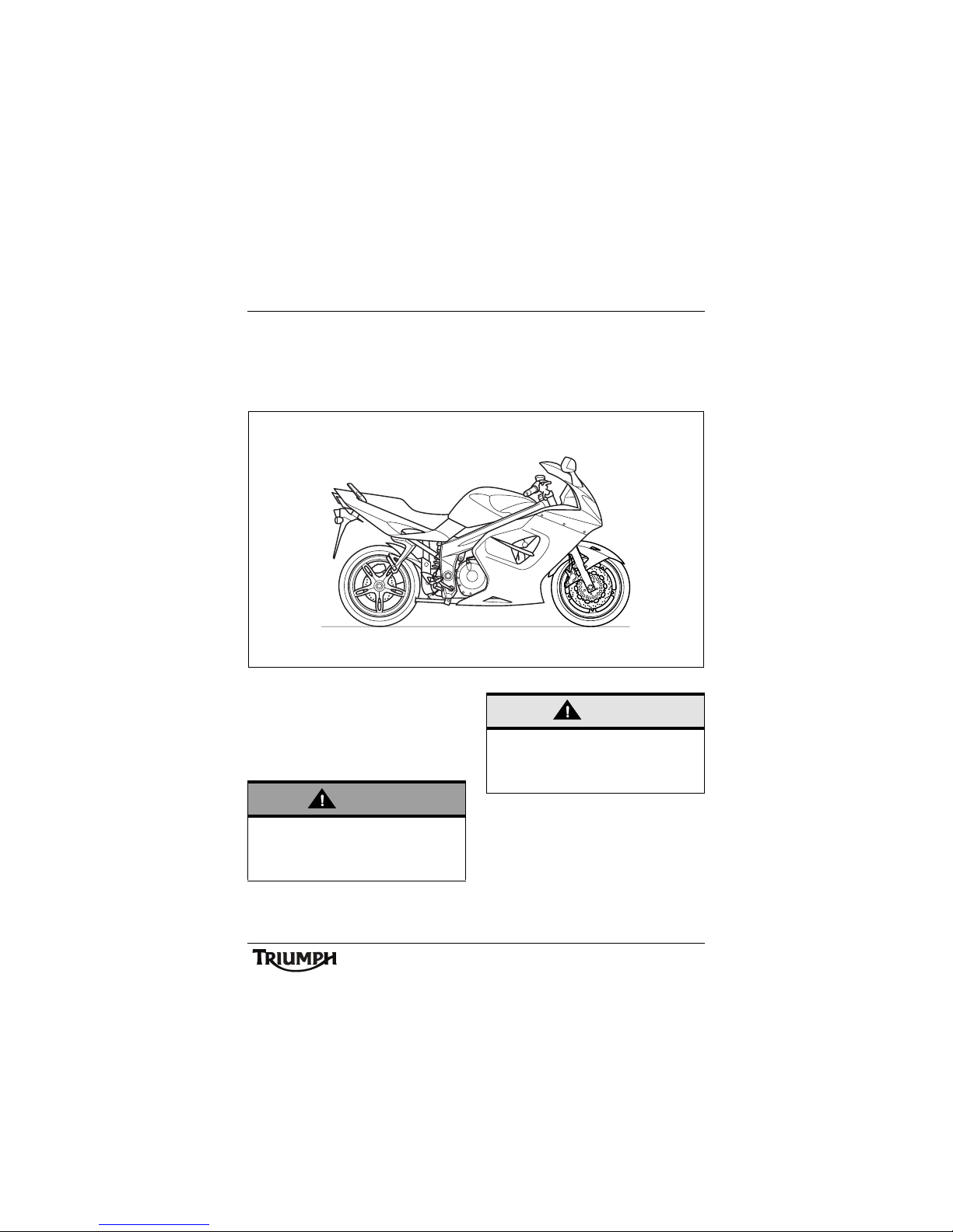
FOREWORD
This handbook contains information on the Triumph Sprint ST and Sprint ST ABS motorcycles.
Always store this owner's handbook with the motorcycle and refer to it for information
whenever necessary.
Warnings, Cautions and
Notes
Throughout this owner's handbook
particularly important information is
presented in the following form:
Note:
• This note symbol indicates points
of particular interest for more
efficient and convenient operation.
ccpx
Warning
This warning symbol identifies special
instructions or procedures, which, if not
correctly followed, could result in personal
injury, or loss of life.
Caution
This caution symbol identifies special
instructions or procedures, which, if not
strictly observed, could result in damage to,
or destruction of, equipment.
2
Foreword
Warning Labels
At certain areas of the
motorcycle, the symbol (left)
can be seen. The symbol
means 'CAUTION: REFER TO
THE HANDBOOK' and will
be followed by a pictorial
representation of the subject
concerned.
Never attempt to ride the motorcycle or
make any adjustments without reference to
the relevant instructions contained in this
handbook.
See pages 10 and 11 for the location of all
labels bearing this symbol. Where necessary,
this symbol will also appear on the pages
containing the relevant information.
Maintenance
To ensure a long, safe and trouble free life for
your motorcycle, maintenance should only be
carried out by an authorised Triumph dealer.
Only an authorised Triumph dealer will have
the necessary knowledge, equipment and
skills to maintain your Triumph motorcycle
correctly.
To locate your nearest Triumph dealer, visit
the Triumph web site at www.triumph.co.uk
or telephone the authorised distributor in
your country. Their address is given in the
service record book that accompanies this
handbook.
Noise Control System
Tampering with the Noise Control System is
Prohibited.
Owners are warned that the law may
prohibit:
a) The removal or rendering
inoperative by any person other than
for purposes of maintenance, repair
or replacement, of any device or
element of design incorporated into
any new vehicle for the purpose of
noise control prior to its sale or
delivery to the ultimate purchaser or
while it is in use and,
b) the use of the vehicle after such
device or element of design has
been removed or rendered
inoperative by any person.
3
Foreword
Owner's Handbook
Thank you for choosing a Triumph
motorcycle. This motorcycle is the product of
Triumph's use of proven engineering,
exhaustive testing, and continuous striving for
superior reliability, safety and performance.
Please read this owner's handbook before
riding in order to become thoroughly familiar
with the correct operation of your
motorcycle's controls, its features, capabilities
and limitations.
This handbook includes safe riding tips, but
does not contain all the techniques and skills
necessary to ride a motorcycle safely.
Triumph strongly recommends that all riders
undertake the necessary training to ensure
safe operation of this motorcycle.
Information
The information contained in this publication
is based on the latest information available at
the time of printing. Triumph reserves the
right to make changes at any time without
prior notice, or obligation.
Not to be reproduced wholly or in part
without the written permission of
Triumph Motorcycles Limited.
© Copyright 04.2008 Triumph Motorcycles
Limited, Hinckley, Leicestershire, England.
Publication part number 3851501 issue 5.
Warning
This owner's handbook, and all other
instructions that are supplied with your
motorcycle, should be considered a
permanent part of your motorcycle and
should remain with it even if your
motorcycle is subsequently sold.
All riders must read this owner's handbook
and all other instructions which are
supplied with your motorcycle, before
riding, in order to become thoroughly
familiar with the correct operation of your
motorcycle's controls, its features,
capabilities and limitations. Do not lend
your motorcycle to others as riding when
not familiar with your motorcycle's
controls, features, capabilities and
limitations can lead to an accident.

Foreword
4
Table of Contents
This handbook contains a number of different sections. The table of contents below will help
you find the beginning of each section where, in the case of the major sections, a further table
of contents will help you find the specific subject required.
Foreword. . . . . . . . . . . . . . . . . . . . . . . . . . . . . . . . . . . . . . . . . . . . . . . . . . . . . . . . . . . . . . . . . . . . 1
Warning Labels. . . . . . . . . . . . . . . . . . . . . . . . . . . . . . . . . . . . . . . . . . . . . . . . . . . . . . . . . . . . . . 10
Parts Identification. . . . . . . . . . . . . . . . . . . . . . . . . . . . . . . . . . . . . . . . . . . . . . . . . . . . . . . . . . . . 12
Serial Numbers. . . . . . . . . . . . . . . . . . . . . . . . . . . . . . . . . . . . . . . . . . . . . . . . . . . . . . . . . . . . . . 15
General Information . . . . . . . . . . . . . . . . . . . . . . . . . . . . . . . . . . . . . . . . . . . . . . . . . . . . . . . . . . 17
How to Ride the Motorcycle . . . . . . . . . . . . . . . . . . . . . . . . . . . . . . . . . . . . . . . . . . . . . . . . . . . 45
Accessories, Loading and Passengers . . . . . . . . . . . . . . . . . . . . . . . . . . . . . . . . . . . . . . . . . . . . 57
Maintenance and Adjustment . . . . . . . . . . . . . . . . . . . . . . . . . . . . . . . . . . . . . . . . . . . . . . . . . . 61
Storage . . . . . . . . . . . . . . . . . . . . . . . . . . . . . . . . . . . . . . . . . . . . . . . . . . . . . . . . . . . . . . . . . . . 10 7
Specifications . . . . . . . . . . . . . . . . . . . . . . . . . . . . . . . . . . . . . . . . . . . . . . . . . . . . . . . . . . . . . . 10 9
5
Foreword - Safety First
FOREWORD - SAFETY FIRST
The Motorcycle Fuel and Exhaust Fumes
Warning
This motorcycle is designed for on-road
use only. It is not suitable for off-road use.
Off-road operation could lead to loss of
control of the motorcycle resulting in an
accident causing injury or loss of life.
Warning
This motorcycle is not designed to tow a
trailer or be fitted with a sidecar. Fitting a
sidecar and/or a trailer may result in loss of
control and an accident.
Warning
This motorcycle is designed for use as a
two-wheeled vehicle capable of carrying a
rider on his/her own, or a rider and one
passenger (subject to a passenger seat
being fitted).
The total weight of the rider, and any
passenger, accessories and luggage must
not exceed the maximum load limit of
215 k g.
Warning
PETROL IS HIGHLY FLAMMABLE:
Always turn off the engine when refuelling.
Do not refuel or open the fuel filler cap
while smoking or in the vicinity of any
open (naked) flame.
Take care not to spill any petrol on the
engine, exhaust pipes or silencers when
refuelling.
If petrol is swallowed, inhaled or allowed to
get into the eyes, seek immediate medical
attention.
Spillage on the skin should be immediately
washed off with soap and water and
clothing contaminated with petrol should
immediately be removed.
Burns and other serious skin conditions
may result from contact with petrol.
Warning
Never start your engine or let it run for any
length of time in a closed area. The
exhaust fumes are poisonous and may
cause loss of consciousness and death
within a short time. Always operate your
motorcycle in the open-air or in an area
with adequate ventilation.
6
Foreword - Safety First
Riding
Warning
Never ride the motorcycle when fatigued
or under the influence of alcohol or other
drugs.
Riding when under the influence of alcohol
or other drugs is illegal.
Riding when fatigued or under the
influence of alcohol or other drugs reduces
the rider's ability to maintain control of the
motorcycle and may lead to loss of control
and an accident.
Warning
All riders must be licenced to operate the
motorcycle. Operation of the motorcycle
without a licence is illegal and could lead to
prosecution.
Operation of the motorcycle without
formal training in the correct riding
techniques that are necessary to become
licenced is dangerous and may lead to loss
of motorcycle control and an accident.
Warning
Always ride defensively and wear the
protective equipment mentioned
elsewhere in this foreword. Remember, in
an accident, a motorcycle does not give the
same impact protection as a car.
Warning
This Triumph motorcycle should be
operated within the legal speed limits for
the particular road travelled. Operating a
motorcycle at high speeds can be
potentially dangerous since the time
available to react to given traffic situations
is greatly reduced as road speed increases.
Always reduce speed in potentially
hazardous driving conditions such as bad
weather or heavy traffic.
Warning
Continually observe and react to changes
in road surface, traffic and wind conditions.
All two-wheeled vehicles are subject to
external forces which may cause an
accident. These forces include but are not
limited to:
• Wind draft from passing vehicles;
• Potholes, uneven or damaged
road surfaces;
• Bad weather;
• Rider error.
Always operate the motorcycle at
moderate speed and away from heavy
traffic until you have become thoroughly
familiar with its handling and operating
characteristics. Never exceed the legal
speed limit.
7
Foreword - Safety First
Helmet and Clothing Handlebars and Footrests
Warning
When riding the motorcycle, both rider
and passenger must always wear a
motorcycle helmet, eye protection, gloves,
trousers (close fitting around the knee and
ankle) and a brightly coloured jacket.
Brightly coloured clothing will considerably
increase a rider's (or passenger's) visibility
to other operators of road vehicles.
Although full protection is not possible,
wearing correct protective clothing can
reduce the risk of injury when riding.
Warning
A helmet is one of the most important
pieces of riding gear as it offers protection
against head injuries. You and your
passenger's helmet should be carefully
chosen and should fit you or your
passenger's head comfortably and
securely. A brightly coloured helmet will
increase a rider's (or passenger's) visibility
to other operators of road vehicles.
An open face helmet offers some
protection in an accident though a full face
helmet will offer more.
Always wear a visor or approved goggles
to help vision and to protect your eyes.
Warning
The rider must maintain control of the
vehicle by keeping hands on the
handlebars at all times.
The handling and stability of a motorcycle
will be adversely affected if the rider
removes his hands from the handlebars,
resulting in loss of motorcycle control and
an accident.
Warning
The rider and passenger must always use
the footrests provided, during operation of
the vehicle.
By using the footrests, both rider and
passenger will reduce the risk of
inadvertent contact with any motorcycle
components and will also reduce the risk of
injury from entrapment of clothing.
8
Foreword - Safety First
Parking Parts and Accessories
Triumph does not accept any liability
whatsoever for defects caused by the fitting
of non-approved parts, accessories or
conversions or the fitting of any approved
parts, accessories or conversions by
non-approved personnel.
Warning
Always turn off the engine and remove the
ignition key before leaving the motorcycle
unattended. By removing the key, the risk
of use of the motorcycle by unauthorised
or untrained persons is reduced.
When parking the motorcycle, always
remember the following:
Engage first gear to help prevent the
motorcycle from rolling off the stand.
The engine and exhaust system will be hot
after riding. DO NOT park where
pedestrians, animals and/or children are
likely to touch the motorcycle.
Do not park on soft ground or on a steeply
inclined surface. Parking under these
conditions may cause the motorcycle to fall
over.
For further details, please refer to the 'How
to Ride the Motorcycle' section of this
owner's handbook.
Warning
Owners should be aware that the only
approved parts, accessories and
conversions for any Triumph motorcycle
are those which carry official Triumph
approval and are fitted to the motorcycle
by an authorised dealer.
In particular, it is extremely hazardous to fit
or replace parts or accessories whose fitting
requires the dismantling of, or addition to,
either the electrical or fuel systems and any
such modification could cause a safety
hazard.
The fitting of any non-approved parts,
accessories or conversions may adversely
affect the handling, stability or other aspect
of the motorcycle operation that may result
in an accident causing injury or death.
9
Foreword - Safety First
Maintenance/Equipment
Warning
Consult your authorised Triumph dealer
whenever there is doubt as to the correct
or safe operation of this Triumph
motorcycle.
Remember that continued operation of an
incorrectly performing motorcycle may
aggravate a fault and may also
compromise safety.
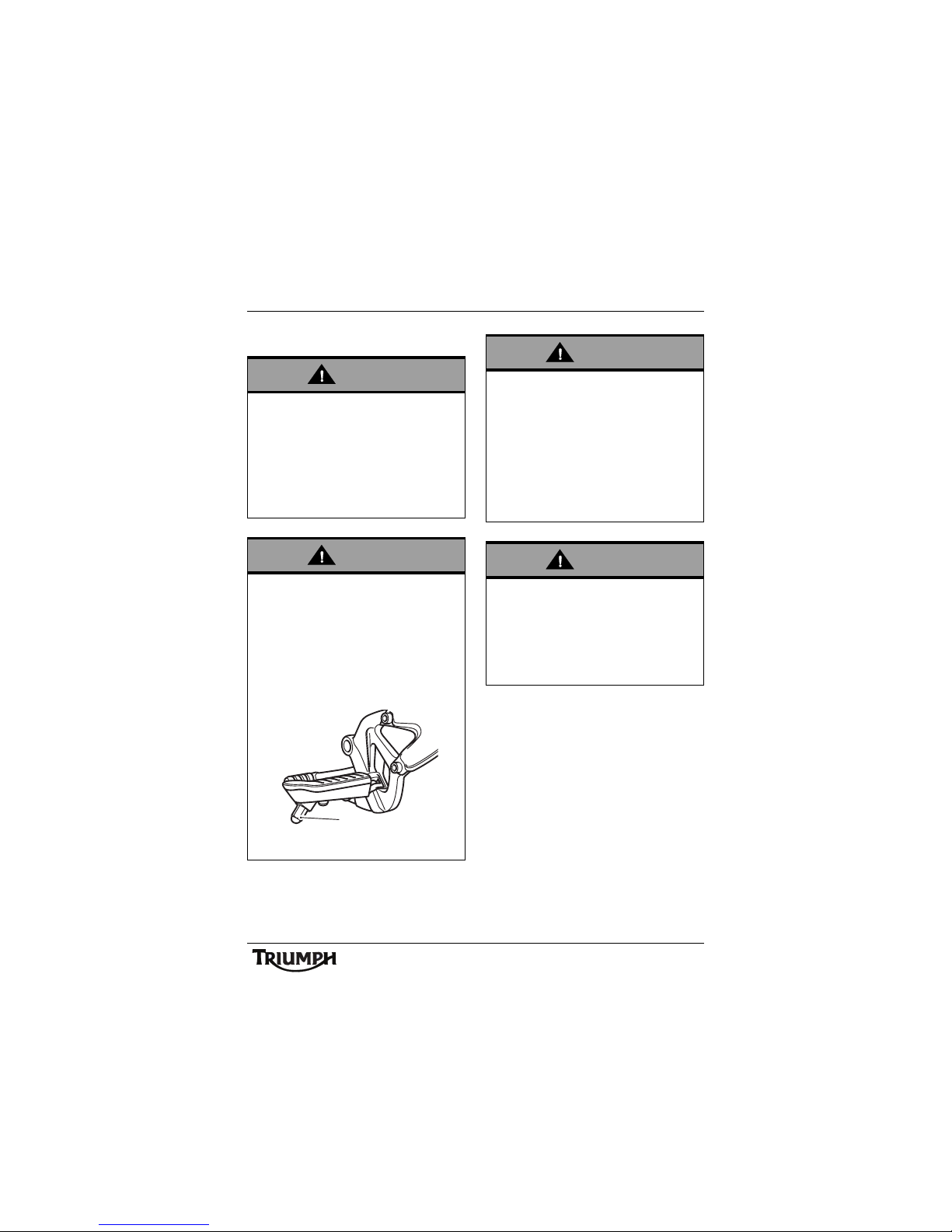
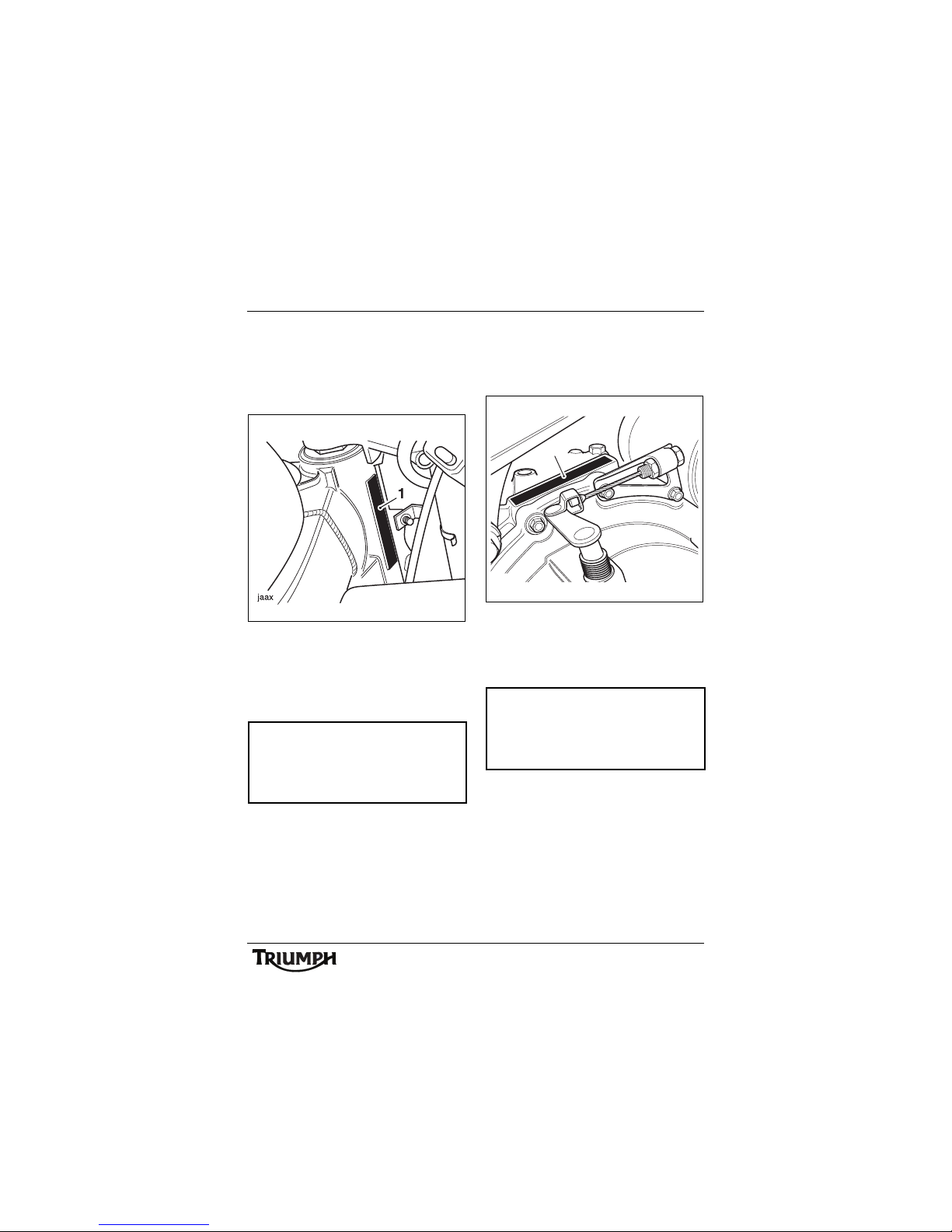
Warning
Use of a motorcycle with bank angle
indicators worn beyond the maximum
limit (when 5 mm of the bank indicator
remains) will allow the motorcycle to be
banked to an unsafe angle.
Banking to an unsafe angle may cause
instability, loss of motorcycle control and
an accident.
1. Bank angle indicator
ccsm
1
Warning
Ensure all equipment that is required by
law is installed and functioning correctly.
The removal or alteration of the
motorcycle's lights, silencers, emission or
noise control systems can violate the law.
Incorrect or improper modification may
adversely affect the handling, stability or
other aspect of the motorcycle operation,
which may result in an accident causing
injury or death.
Warning
If the motorcycle is involved in an accident,
collision or fall, it must be taken to an
authorised Triumph dealer for inspection
and repair. Any accident can cause
damage to the motorcycle that, if not
correctly repaired, may cause a second
accident that may result in injury or death.

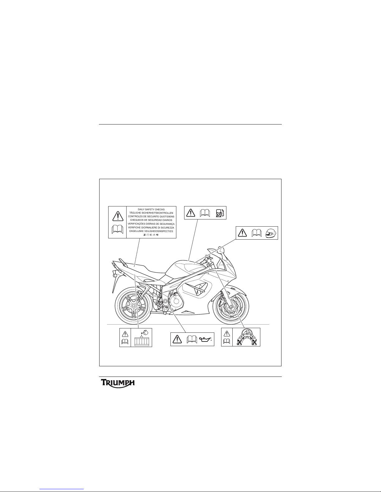
Warning Labels
10
WARNING LABELS
The labels detailed on this and the following pages draw your attention to important safety
information in this handbook. Before riding, ensure that all riders have understood and
complied with all the information to which these labels relate.
Warning Label Locations
6
5
4
3
2
N
1
R.P.M.
ccot
Running-In
(page 42)
Windscreen
(page 84)
Gear
Posi tio n
(page 48)
Chain
(page 76)
Tyr es
(page 89)
Warning Labels
11
WARNING LABELS
Warning Label Locations (continued)
ccou
Daily Safety Checks
(page 43)
Unleaded Fuel
(page 32)
Helmet
(page 7)
Coolant
(page 70)
Engine Oil
(page 67)
Fairing Stowage
(page 59)
12
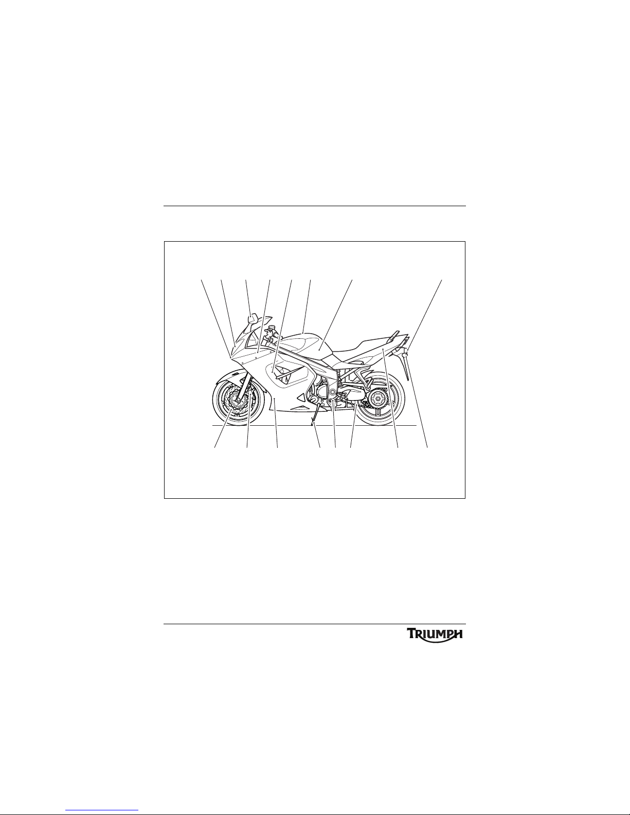
Parts Identification
PARTS IDENTIFICATION
1. Front indicator
2. Headlight
3. Position lamp
4. Rear light
5. Radiator/Coolant pressure cap
6. Oil cooler
7. Drive chain
8. Side stand
9. Rear indicator
10.Gear-change pedal
11. Front brake disc
12. Front brake caliper
13 . Fu el ta nk
14. Fuel filler cap
15.Coolant expansion tank
16 . S i l e n c e r
ccmq
52 14
16
1 13
15
4
7108 911 12 6
3
13
Parts Identification
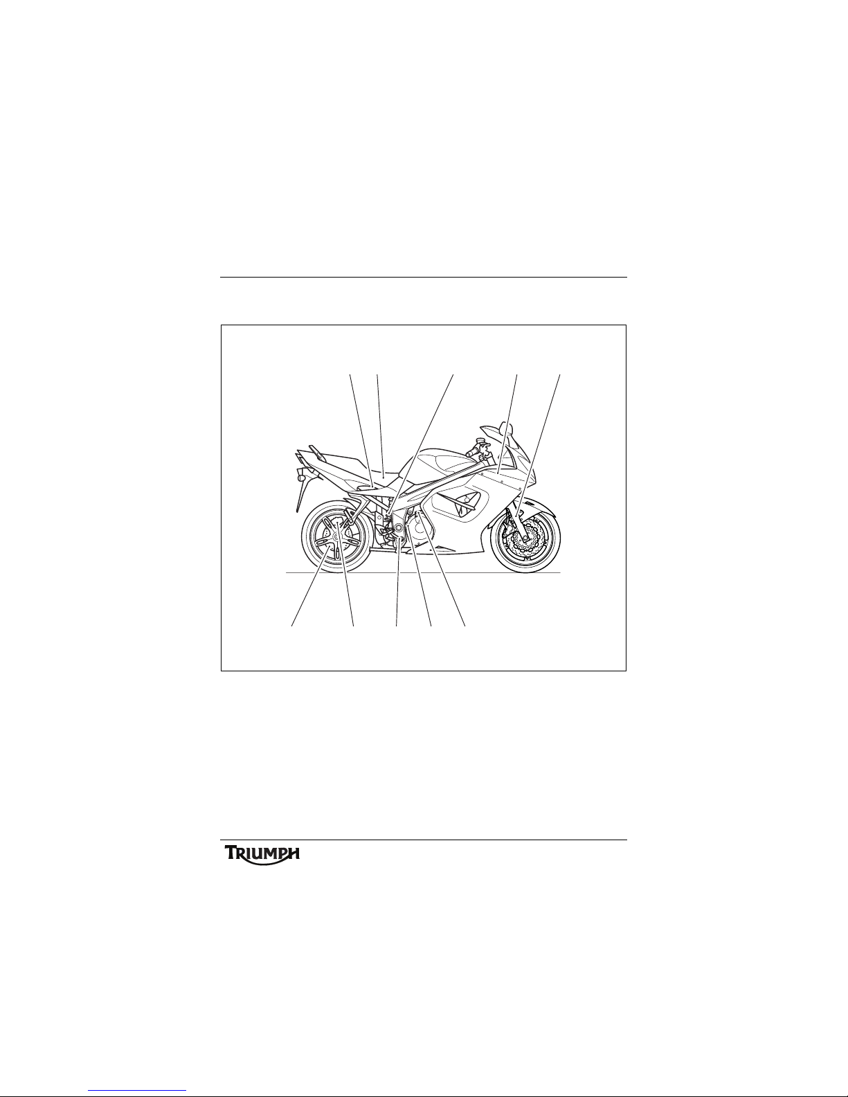
PARTS IDENTIFICATION
17.Battery
18.Tool kit
19.Rear brake disc
20.Rear brake caliper
21.Rear brake fluid reservoir
22.Rear brake pedal
23.Oil filler cap/Dipstick
24.Clutch cable
25.Front fork
26.Rear suspension unit
18
22
19
26
25
2423
20
21
ccmp
17
14
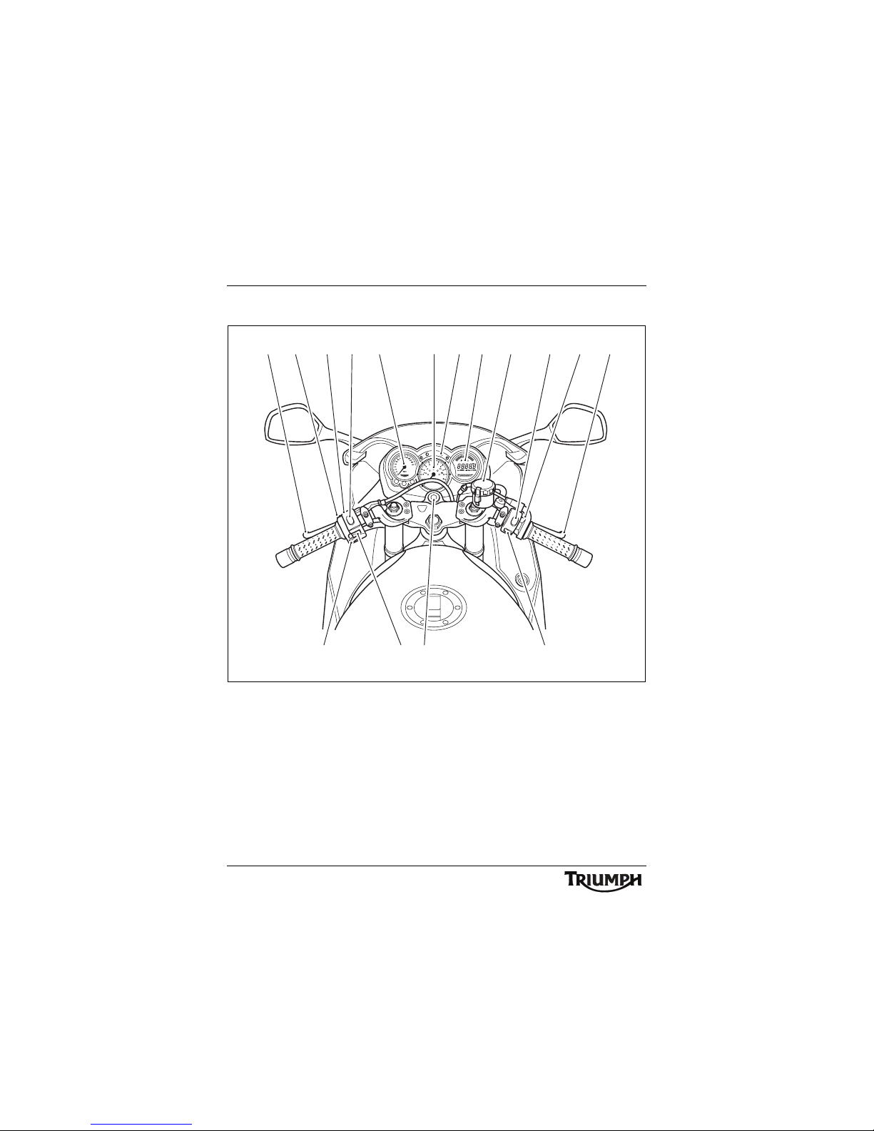
Parts Identification
Parts Identification (continued)
1. C l u t ch le ve r
2. Passing button
3. Headlight dip switch
4. Horn button
5. Direction indicator switch
6. Ignition switch
7. Front brake fluid reservoir
8. Front brake lever
9. Engine stop switch
10.Starter button
11. Tachometer
12.Speedometer
13.Warning lights
14.Trip computer
15.Clutch lever adjuster
16.Brake lever adjuster
1215 32 11 13 14 7 9 816
6 104 5
1
15
Serial Numbers
SERIAL NUMBERS
Vehicle Identification
Number (VIN)
The vehicle identification number is stamped
into the steering head area of the frame. It is
also displayed on a plate, riveted to the
frame, immediately behind the steering head.
Record the vehicle identification number in
the space below.
Engine Serial Number
The engine serial number is stamped on the
engine crankcase, immediately above the
clutch cover.
Record the engine serial number in the space
provided below.
ccmy
1

16
Serial Numbers
This page intentionally left blank

General Information
17
GENERAL INFORMATION
Table of Contents
Instrument Panel Layout. . . . . . . . . . . . . . . . . . . . . . . . . . . . . . . . . . . . . . . . . . . . . . . . . . . . . . . .19
Speedometer . . . . . . . . . . . . . . . . . . . . . . . . . . . . . . . . . . . . . . . . . . . . . . . . . . . . . . . . . . . . . . . 20
Tachometer . . . . . . . . . . . . . . . . . . . . . . . . . . . . . . . . . . . . . . . . . . . . . . . . . . . . . . . . . . . . . . . . . 20
Odometer/Trip Meter. . . . . . . . . . . . . . . . . . . . . . . . . . . . . . . . . . . . . . . . . . . . . . . . . . . . . . . . . 20
Clock/Trip Computer . . . . . . . . . . . . . . . . . . . . . . . . . . . . . . . . . . . . . . . . . . . . . . . . . . . . . . . . . 21
Instantaneous Fuel Consumption . . . . . . . . . . . . . . . . . . . . . . . . . . . . . . . . . . . . . . . . . . . . 21
Average Fuel Consumption . . . . . . . . . . . . . . . . . . . . . . . . . . . . . . . . . . . . . . . . . . . . . . . . 21
Range. . . . . . . . . . . . . . . . . . . . . . . . . . . . . . . . . . . . . . . . . . . . . . . . . . . . . . . . . . . . . . . . . . 21
Journey Distance . . . . . . . . . . . . . . . . . . . . . . . . . . . . . . . . . . . . . . . . . . . . . . . . . . . . . . . . . 21
Journey Time . . . . . . . . . . . . . . . . . . . . . . . . . . . . . . . . . . . . . . . . . . . . . . . . . . . . . . . . . . . . 21
Average Speed . . . . . . . . . . . . . . . . . . . . . . . . . . . . . . . . . . . . . . . . . . . . . . . . . . . . . . . . . . 21
Maximum Speed . . . . . . . . . . . . . . . . . . . . . . . . . . . . . . . . . . . . . . . . . . . . . . . . . . . . . . . . 21
Trip Computer Operation . . . . . . . . . . . . . . . . . . . . . . . . . . . . . . . . . . . . . . . . . . . . . . . . . . 21
Trip Computer Reset . . . . . . . . . . . . . . . . . . . . . . . . . . . . . . . . . . . . . . . . . . . . . . . . . . . . . . 22
Clock Adjustment . . . . . . . . . . . . . . . . . . . . . . . . . . . . . . . . . . . . . . . . . . . . . . . . . . . . . . . . 22
Coolant Temperature Gauge . . . . . . . . . . . . . . . . . . . . . . . . . . . . . . . . . . . . . . . . . . . . . . . . . . . 23
Fuel Gauge . . . . . . . . . . . . . . . . . . . . . . . . . . . . . . . . . . . . . . . . . . . . . . . . . . . . . . . . . . . . . . . . . 24
Warning Lights . . . . . . . . . . . . . . . . . . . . . . . . . . . . . . . . . . . . . . . . . . . . . . . . . . . . . . . . . . . . . . 25
Direction Indicators . . . . . . . . . . . . . . . . . . . . . . . . . . . . . . . . . . . . . . . . . . . . . . . . . . . . . . . 25
High Beam. . . . . . . . . . . . . . . . . . . . . . . . . . . . . . . . . . . . . . . . . . . . . . . . . . . . . . . . . . . . . . 25
Low Fuel. . . . . . . . . . . . . . . . . . . . . . . . . . . . . . . . . . . . . . . . . . . . . . . . . . . . . . . . . . . . . . . . 25
Neutral . . . . . . . . . . . . . . . . . . . . . . . . . . . . . . . . . . . . . . . . . . . . . . . . . . . . . . . . . . . . . . . . . 25
Low Oil Pressure Warning Light. . . . . . . . . . . . . . . . . . . . . . . . . . . . . . . . . . . . . . . . . . . . . 25
High Coolant Temperature Warning Light. . . . . . . . . . . . . . . . . . . . . . . . . . . . . . . . . . . . . 25
Engine Management System Malfunction Indicator Light . . . . . . . . . . . . . . . . . . . . . . . . 26
ABS (Anti-Lock Brake System) Indicator Light . . . . . . . . . . . . . . . . . . . . . . . . . . . . . . . . . . 26
Alarm Indicator Light. . . . . . . . . . . . . . . . . . . . . . . . . . . . . . . . . . . . . . . . . . . . . . . . . . . . . . 26
Ignition Key. . . . . . . . . . . . . . . . . . . . . . . . . . . . . . . . . . . . . . . . . . . . . . . . . . . . . . . . . . . . . . . . . 27
Ignition Switch/Steering Lock. . . . . . . . . . . . . . . . . . . . . . . . . . . . . . . . . . . . . . . . . . . . . . . . . . . 28
Ignition Switch Positions . . . . . . . . . . . . . . . . . . . . . . . . . . . . . . . . . . . . . . . . . . . . . . . . . . . 28

General Information
18
Brake and Clutch Lever Adjusters . . . . . . . . . . . . . . . . . . . . . . . . . . . . . . . . . . . . . . . . . . . . . . . 29
Right Handlebar Switches . . . . . . . . . . . . . . . . . . . . . . . . . . . . . . . . . . . . . . . . . . . . . . . . . . . . . 30
Engine Stop Switch . . . . . . . . . . . . . . . . . . . . . . . . . . . . . . . . . . . . . . . . . . . . . . . . . . . . . . . 30
Starter Button . . . . . . . . . . . . . . . . . . . . . . . . . . . . . . . . . . . . . . . . . . . . . . . . . . . . . . . . . . . 30
Left Handlebar Switches. . . . . . . . . . . . . . . . . . . . . . . . . . . . . . . . . . . . . . . . . . . . . . . . . . . . . . . 31
Headlight Dip Switch. . . . . . . . . . . . . . . . . . . . . . . . . . . . . . . . . . . . . . . . . . . . . . . . . . . . . . 31
Direction Indicator Switch . . . . . . . . . . . . . . . . . . . . . . . . . . . . . . . . . . . . . . . . . . . . . . . . . . 31
Horn Button. . . . . . . . . . . . . . . . . . . . . . . . . . . . . . . . . . . . . . . . . . . . . . . . . . . . . . . . . . . . . 31
Pass Button . . . . . . . . . . . . . . . . . . . . . . . . . . . . . . . . . . . . . . . . . . . . . . . . . . . . . . . . . . . . . 31
Fuel Requirement/Refuelling . . . . . . . . . . . . . . . . . . . . . . . . . . . . . . . . . . . . . . . . . . . . . . . . . . . 32
Fuel Grade . . . . . . . . . . . . . . . . . . . . . . . . . . . . . . . . . . . . . . . . . . . . . . . . . . . . . . . . . . . . . . 32
Fuel Tank Cap . . . . . . . . . . . . . . . . . . . . . . . . . . . . . . . . . . . . . . . . . . . . . . . . . . . . . . . . . . . 33
Filling the Fuel Tank. . . . . . . . . . . . . . . . . . . . . . . . . . . . . . . . . . . . . . . . . . . . . . . . . . . . . . . 33
Stands . . . . . . . . . . . . . . . . . . . . . . . . . . . . . . . . . . . . . . . . . . . . . . . . . . . . . . . . . . . . . . . . . . . . . 34
Side Stand . . . . . . . . . . . . . . . . . . . . . . . . . . . . . . . . . . . . . . . . . . . . . . . . . . . . . . . . . . . . . . 34
Centre Stand . . . . . . . . . . . . . . . . . . . . . . . . . . . . . . . . . . . . . . . . . . . . . . . . . . . . . . . . . . . . 35
Lifting Handle . . . . . . . . . . . . . . . . . . . . . . . . . . . . . . . . . . . . . . . . . . . . . . . . . . . . . . . . . . . 35
Tool Kit and Handbook . . . . . . . . . . . . . . . . . . . . . . . . . . . . . . . . . . . . . . . . . . . . . . . . . . . . . . . 36
Seat Fasteners . . . . . . . . . . . . . . . . . . . . . . . . . . . . . . . . . . . . . . . . . . . . . . . . . . . . . . . . . . . . . . . 36
Seat Care . . . . . . . . . . . . . . . . . . . . . . . . . . . . . . . . . . . . . . . . . . . . . . . . . . . . . . . . . . . . . . . 37
Pannier System . . . . . . . . . . . . . . . . . . . . . . . . . . . . . . . . . . . . . . . . . . . . . . . . . . . . . . . . . . . . . . 37
Pannier Operation . . . . . . . . . . . . . . . . . . . . . . . . . . . . . . . . . . . . . . . . . . . . . . . . . . . . . . . . 39
Electrical Accessory Socket . . . . . . . . . . . . . . . . . . . . . . . . . . . . . . . . . . . . . . . . . . . . . . . . . . . . . 41
Running-In . . . . . . . . . . . . . . . . . . . . . . . . . . . . . . . . . . . . . . . . . . . . . . . . . . . . . . . . . . . . . . . . . 42
Safe Operation . . . . . . . . . . . . . . . . . . . . . . . . . . . . . . . . . . . . . . . . . . . . . . . . . . . . . . . . . . . . . . 43
Daily Safety Checks . . . . . . . . . . . . . . . . . . . . . . . . . . . . . . . . . . . . . . . . . . . . . . . . . . . . . . . 43

19
General Information
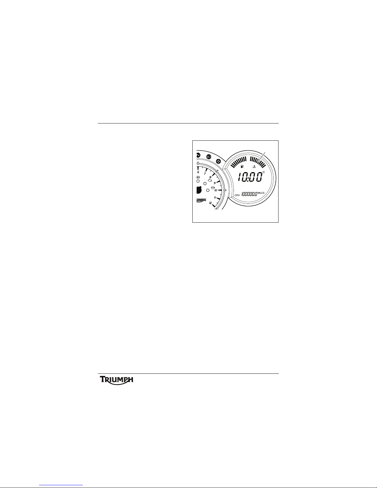
Instrument Panel Layout
1. Tachometer
2. Tachometer 'red zone'
3. Speedometer
4. Odometer/Trip meters
5. Clock/Trip computer display
6. Scroll/Set/Trip buttons
7. Coolant temperature display
8. Fuel gauge
9. Low oil pressure warning light
10.High coolant temperature warning
light
11. Engine management malfunction
indicator light
12. ABS warning light (ABS models only)
13. Low fuel level indicator light
14.Neutral indicator light
15.High beam indicator light
16. Right turn indicator light
17.Left turn indicator light
18.Alarm status indicator light (alarm is
an accessory fit)
ccmk
km/h
17 15 1613 14 8 75
10
12 18111 2 46 9
3
20
General Information
Speedometer
The speedometer indicates the road speed of
the motorcycle.
Tachometer
The tachometer shows the engine speed in
revolutions per minute - rpm (r/min). On the
right side of the tachometer face is the
'red zone'. Engine rpm (r/min) in the red
zone is above maximum recommended
engine speed and is also above the range for
best performance.
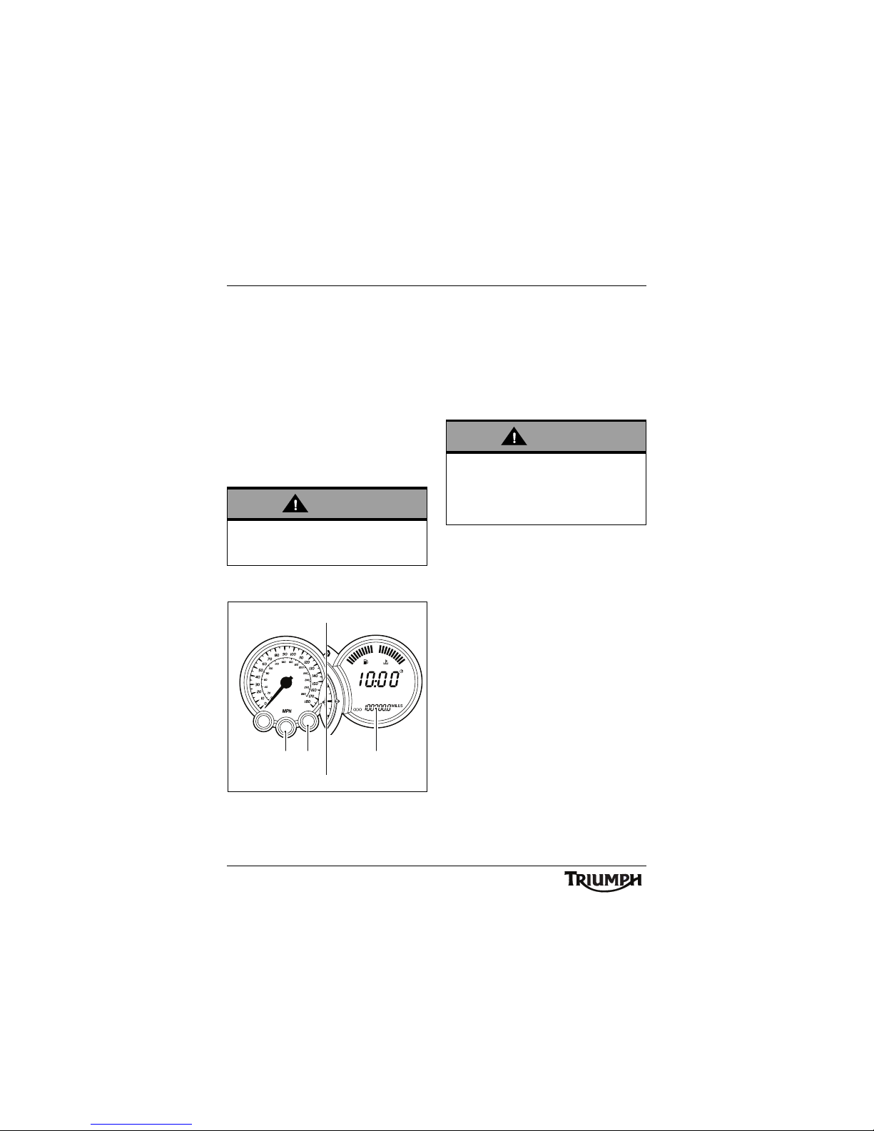
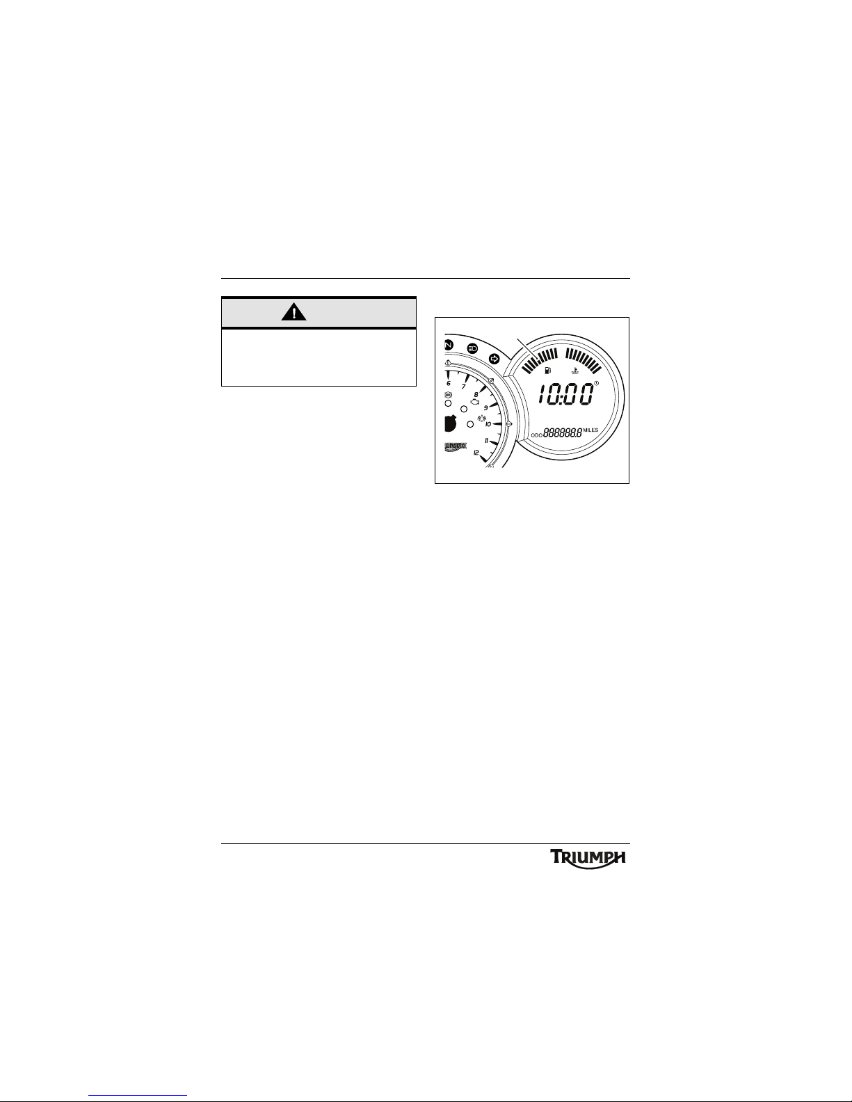
Odometer/Trip Meter
1. Odometer/Trip meter display
2. Set button
3. Trip button
The odometer shows the total distance that
the motorcycle has travelled.
The odometer and two trip meters are
located in the same LCD display as the clock
and trip computer. Either trip meter shows
the distance that the motorcycle has travelled
since the meter on display was last reset to
zero.
Use the 'trip' button to switch between the
odometer and trip meter display modes.
Press the 'trip' button repeatedly until the
desired display is visible. The display will scroll
through in the order:
•Odometer
• Trip Meter 1
• Trip Meter 2
To reset either of the trip meters, select and
display the trip meter to be zeroed then press
the 'trip' button for 2 seconds. After
2 seconds, the trip meter on display will reset
to zero.
Warning
Never allow engine rpm to enter the
'red zone' as severe engine damage may
result.
km/h
12 3
ccqu
Warning
Do not attempt to switch between
odometer and trip meter display modes or
reset the trip meter with the motorcycle in
motion as this may lead to loss of
motorcycle control and an accident.
21
General Information
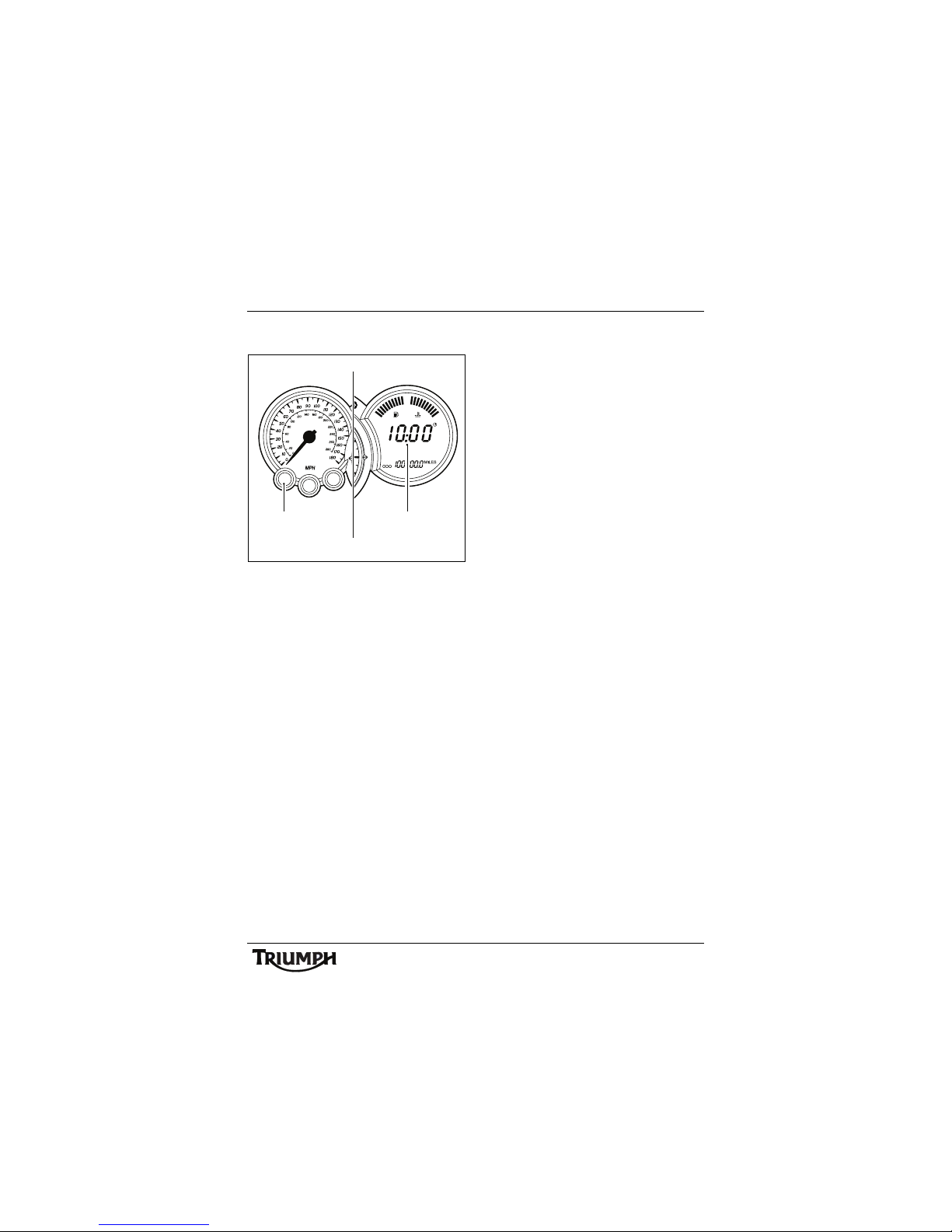
Clock/Trip Computer
1. Clock/Trip computer display
2. Scroll button
The clock and trip computer information
appear on the same display.
The trip computer provides an indication of
fuel consumption, fuel range to empty,
speed, time and distance, recorded and
calculated since the last reset.
Each display provides the following
information:
Instantaneous Fuel Consumption
An indication of the fuel consumption at an
instant in time.
Average Fuel Consumption
An indication of the average fuel
consumption is calculated from when the trip
computer was last reset. After a reset the
display will show dashes until 0.1 miles/km
has been covered.
Range
This is an indication of the probable distance
that can be travelled on the remaining fuel in
the tank.
Journey Distance
The total distance travelled, since the last
reset.
Journey Time
The total time elapsed, since the last reset.
Average Speed
The average speed is calculated from when
the trip computer was last reset. After a reset
the display will show dashes until 1 mile/km
has been covered.
Maximum Speed
The maximum speed achieved since the last
reset is displayed.
Trip Computer Operation
When the ignition is switched on, the clock
display is shown. To access the trip computer
information press the 'scroll' button.
Press the 'scroll' button repeatedly until the
desired display is visible. The trip computer
will scroll through in the order:
•Clock
• Instantaneous Fuel Consumption
• Average Fuel Consumption
•Range
• Journey Distance
• Journey Time
• Average Speed
•Maximum Speed
km/h
12
ccnl
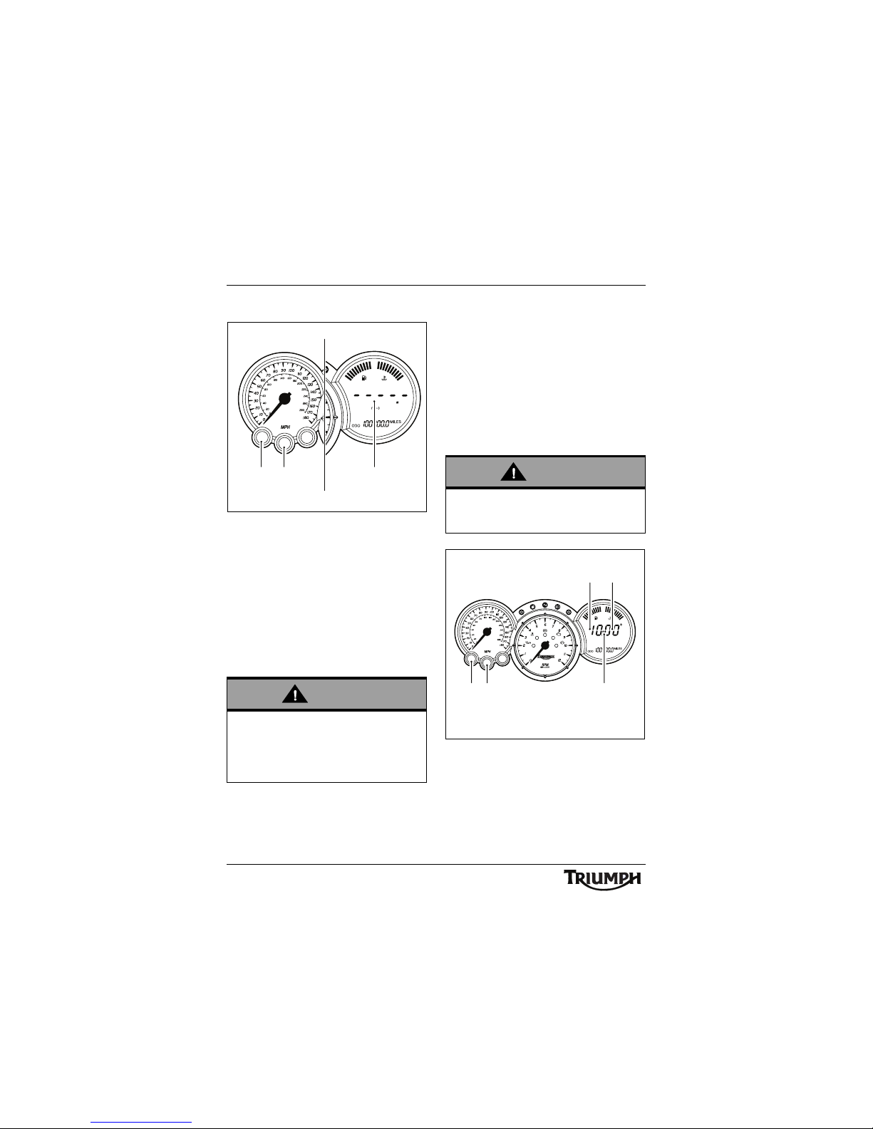
22
General Information
Trip Computer Reset
1. Trip computer display
2. Scroll button
3. Set button
The following displays on the trip computer
can be reset:
• Average Fuel Consumption
•Journey Distance
•Journey Time
•Average Speed
•Maximum Speed
To reset the trip computer select the desired
display, press the 'scroll' and 'set' buttons
simultaneously for 2 seconds. After
2 seconds, the selected display will reset.
Note:
• Journey distance, journey time
and average speed are reset at the
same time.
Clock Adjustment
1. C l o c k d is pl ay
2. Hours read-out
3. Minutes read-out
4. Scroll button
5. Set button
To reset the clock, select the clock display and
press both 'scroll' and 'set' buttons together.
Warning
Do not attempt to switch between the trip
computer display modes or reset the trip
computer with the motorcycle in motion as
this may lead to loss of motorcycle control
and an accident.
ccnk
km/h
132
Warning
Do not attempt to adjust the clock with the
motorcycle in motion as this may lead to
loss of motorcycle control and an accident.
ccnh
km/h
2 3
5
14
23
General Information
After a short time, the clock's hour display will
start to flash.
To reset the hour display, ensure that the
hour display is still flashing then depress the
'scroll' button to change the setting. Each
individual press will change the setting by
one digit. If the button is held, the display will
continuously scroll through in single digit
increments.
When the correct hour display is shown,
press the 'set' button. The minutes display will
begin to flash. The minutes display is
adjusted in the same way as for the hours.
Once both hours and minutes are correctly
set, press the 'set' button to confirm the
setting. The display will cease to flash.
Coolant Temperature Gauge
1. Coolant temperature gauge
The coolant temperature gauge indicates the
temperature of the engine coolant.
When the ignition is switched on, all 10 bars
of the display will be shown. When the
engine is started from cold the display will
show 1 bar. As the temperature increases,
more bars will be shown in the display.
The normal temperature range is between 3
and 6 bars.
If the coolant temperature becomes too high,
the display will show 9 bars and will start to
flash. The high coolant temperature warning
light in the tachometer will also be
illuminated.
If the coolant temperature increases further,
all 10 bars of the display will flash. The high
coolant temperature warning light in the
tachometer will remain illuminated.
ccnj
1
24
General Information
Fuel Gauge
1. Fuel gauge
The fuel gauge indicates the amount of fuel
in the tank.
With the ignition switched on, the number of
bars shown in the display indicates the level
of fuel in the tank.
When the fuel tank is full, all 10 bars are
displayed and when empty, no bars are
displayed. Other gauge markings indicate
intermediate fuel levels between full and
empty.
When 2 bars are displayed, the low fuel
warning light will illuminate. This indicates
there are approximately 4.0 litres of fuel
remaining in the tank and you should refuel
at the earliest opportunity.
After refuelling, the fuel gauge and range to
empty information will be updated only while
riding the motorcycle.
Depending on the riding style, this could take
approximately 5 minutes.
Caution
Do not continue to run the engine if either
of the high temperature warnings are
displayed as severe engine damage may
result.
ccni
1
25
General Information
Warning Lights
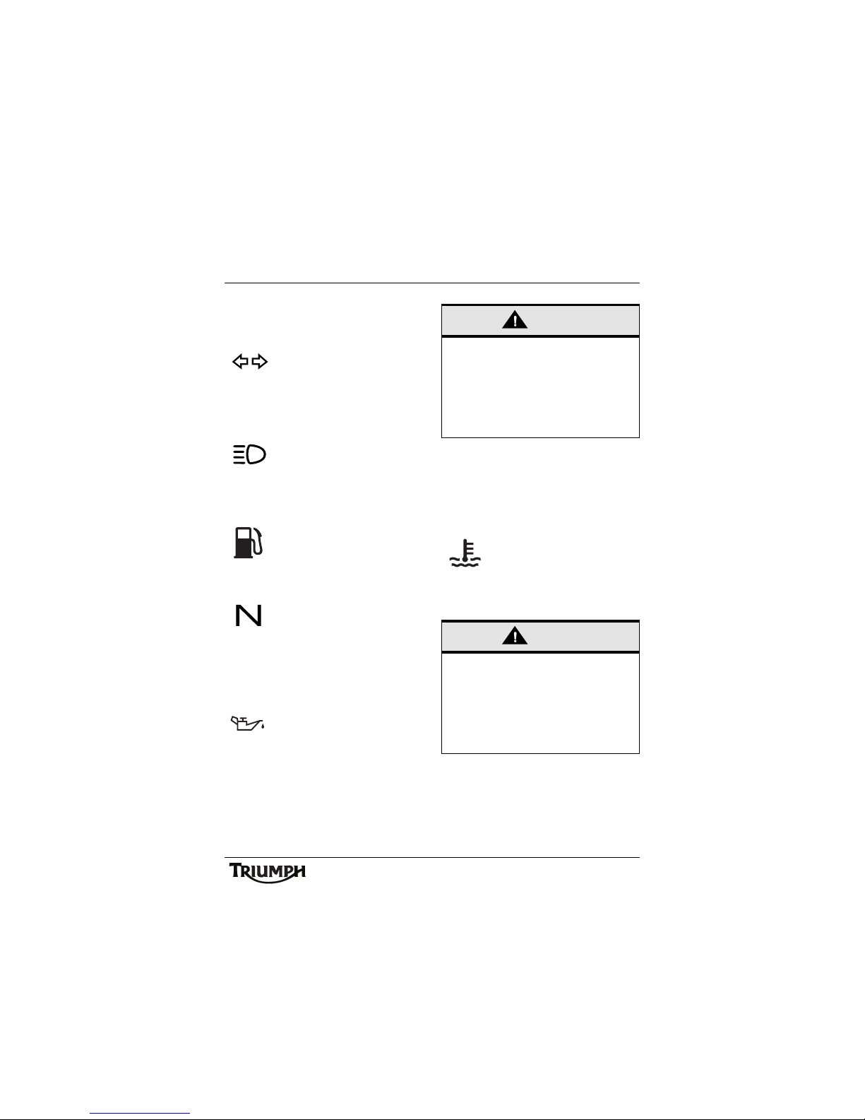
Direction Indicators
When the indicator is pushed to
the left or right, the
corresponding turn indicator
light will flash on and off at the
same speed as the turn indicators.
High Beam
When the ignition is switched
on and the headlight dip switch
is set to 'high beam', the high
beam warning light will illuminate.
Low Fuel
The low fuel indicator will
illuminate when there are
approximately 4.0 litres of fuel
remaining in the tank.
Neutral
The neutral warning light
indicates when the transmission
is in neutral (no gear selected).
The warning light will illuminate when the
transmission is in neutral with the ignition
switch in the ON position.
Low Oil Pressure Warning Light
With the engine running, if the
engine oil pressure becomes
dangerously low, the low oil
pressure warning light in the tachometer will
illuminate.
The low oil pressure warning light in the
tachometer will illuminate if the ignition is
switched on without running the engine.
High Coolant Temperature Warning
Light
With the engine running, if the
engine coolant temperature
becomes dangerously high, the
high coolant temperature
warning light in the tachometer will
illuminate.
The high coolant temperature warning light
in the tachometer will illuminate if the ignition
is switched on without running the engine.
Caution
Stop the engine immediately if the low oil
pressure warning light illuminates. Do not
restart the engine until the fault has been
rectified.
Severe engine damage will result from
running the engine when the low oil
pressure warning light is illuminated.
Caution
Stop the engine immediately if the high
coolant temperature warning light
illuminates. Do not restart the engine until
the fault has been rectified.
Severe engine damage will result from
running the engine when the high coolant
temperature warning light is illuminated.
26
General Information
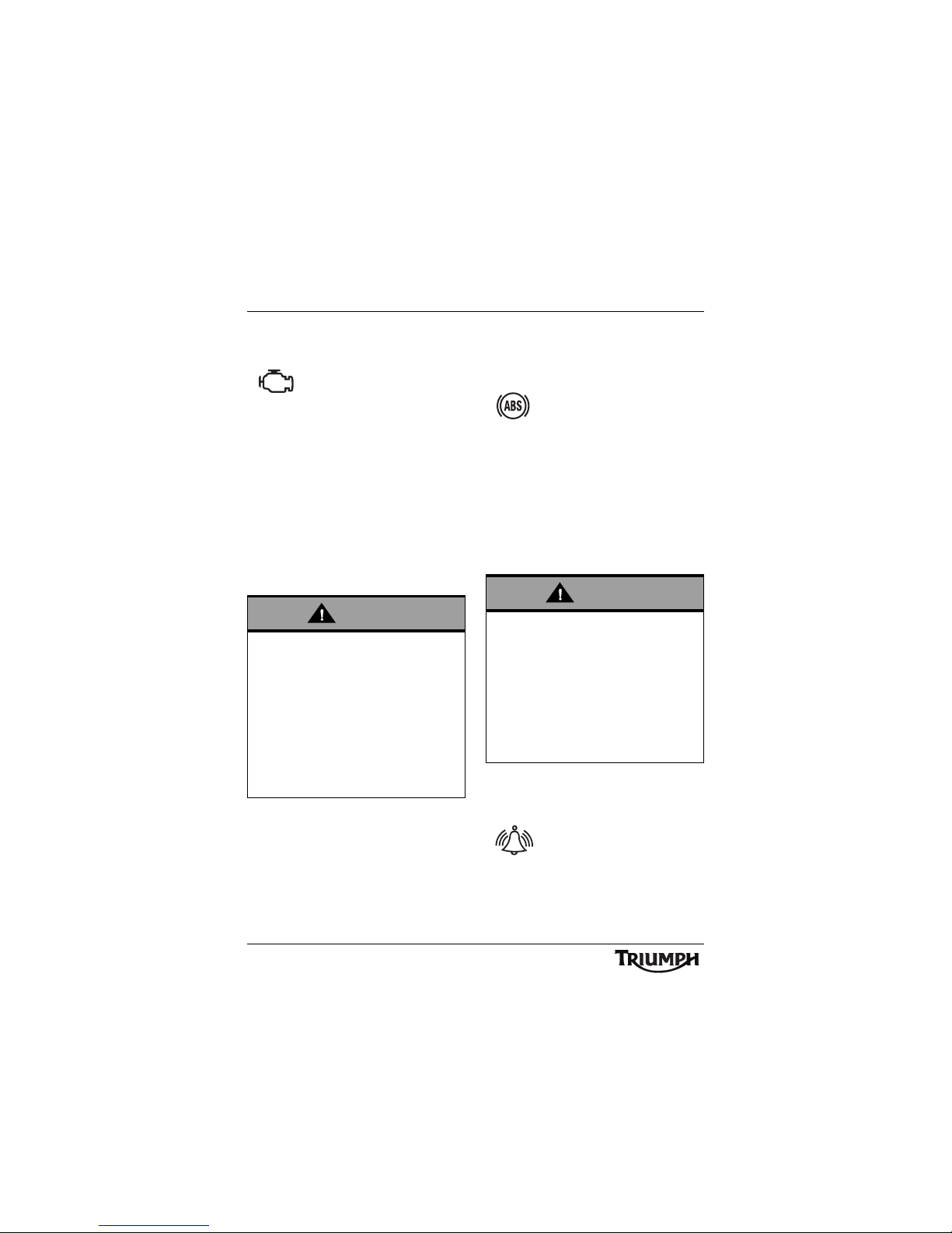
Engine Management System
Malfunction Indicator Light
The malfunction indicator light
for the engine management
system illuminates when the
ignition is switched on (to indicate that it is
working) but should not become illuminated
when the engine is running.
If the malfunction indicator light becomes
illuminated when the engine is running, this
indicates that a fault has occurred in one or
more of the systems controlled by the engine
management system. In such circumstances,
the engine management system will switch to
'limp-home' mode so that the journey may
be completed, if the fault is not so severe that
the engine will not run.
ABS (Anti-Lock Brake System)
Indicator Light
(only on models fitted with ABS)
The ABS indicator light
illuminates to show that the ABS
function is not available.
Illumination is normal after engine start-up,
and until the motorcycle first reaches a speed
exceeding 6 mph (10 km/h). Unless there is a
fault, it should not illuminate again until the
engine is restarted.
If the indicator light becomes illuminated at
any other time while riding it indicates that
the ABS has a malfunction that requires
investigation.
See also Braking on page 49.
Alarm Indicator Light
The alarm light will illuminate
when the conditions described
in the accessory alarm
instructions are met.
The light does not function unless an alarm is
fitted.
Warning
Reduce speed and do not continue to ride
for longer than is necessary with the
malfunction indicator light illuminated. The
fault may adversely affect engine
performance, exhaust emissions and fuel
consumption. Reduced engine
performance could cause a dangerous
riding condition, leading to loss of control
and an accident. Contact an authorised
Triumph dealer as soon as possible to have
the fault checked and rectified.
Warning
If the ABS is not functioning, the brake
system will continue to function as a
non-ABS braking system. Do not continue
to ride for longer than is necessary with the
indicator light illuminated. Contact an
authorised Triumph dealer as soon as
possible to have the fault checked and
rectified. In this situation, braking too hard
will cause the wheels to lock resulting in
loss of control and an accident.
27
General Information
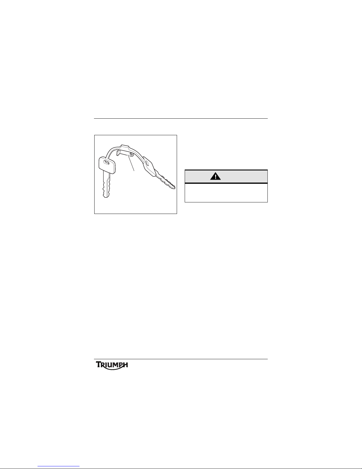
Ignition Key
1. Key number tag
In addition to operating the steering
lock/ignition switch, the ignition key is
required to operate the seat lock and fuel
tank cap.
When the motorcycle is delivered from the
factory, two keys are supplied together with a
small tag bearing the key number. Make a
note of the key number and store the spare
key and key number tag in a safe place away
from the motorcycle.
Your authorised Triumph dealer can supply a
replacement key cut from details of the key
number or can cut a new key using the
original as a master.
Note:
• One unused lock is supplied with
the motorcycle. This is for use with
the optional accessory top box and
will ensure that, when fitted, the
same key will operate all the locks
on the motorcycle.
ccnf
1
Caution
Do not store the spare key with the
motorcycle as this will reduce all aspects of
security.
28
General Information
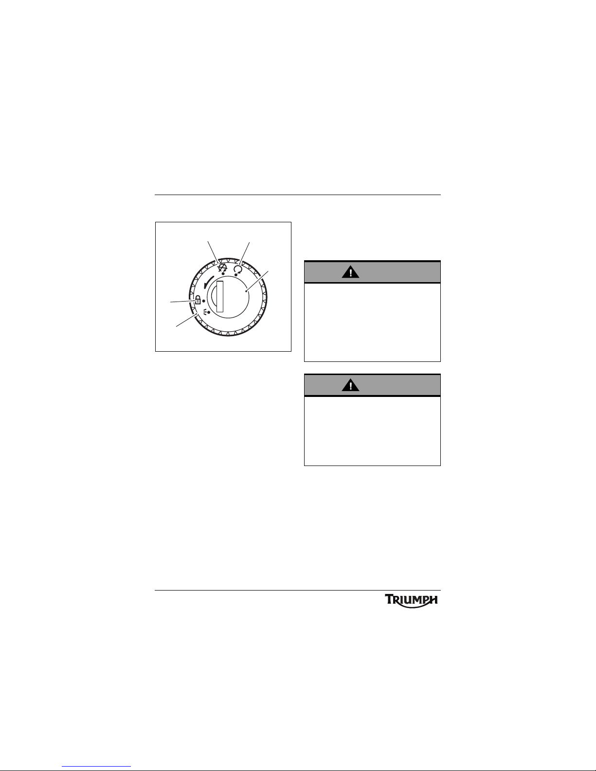
Ignition Switch/Steering Lock
1. Ignition switch/Steering lock
2. LOCK position
3. OFF position
4. ON position
5. PARK position
Ignition Switch Positions
This is a four position, key operated switch.
The key can be removed from the switch
only when it is in the OFF, LOCK or P (PARK)
position.
TO LOCK: Turn the key to the OFF position,
push and fully release the key, then rotate it
to the LOCK position.
PARKING: Turn the key from the LOCK
position to the P position. The steering will
remain locked.
Note:
• Do not leave the steering lock in
the P position for long periods of
time as this will cause the battery
to discharge.
P
U
S
H
P
1
3
4
2
5
Warning
For reasons of security and safety, always
move the ignition switch to the OFF
position and remove the key when leaving
the motorcycle unattended.
Any unauthorised use of the motorcycle
may cause injury to the rider, other road
users and pedestrians and may also cause
damage to the motorcycle.
Warning
With the key in the LOCK or P position the
steering will become locked.
Never turn the key to the LOCK or P
positions while the motorcycle is moving as
this will cause the steering to lock. Locked
steering will cause loss of motorcycle
control and an accident.
29
General Information
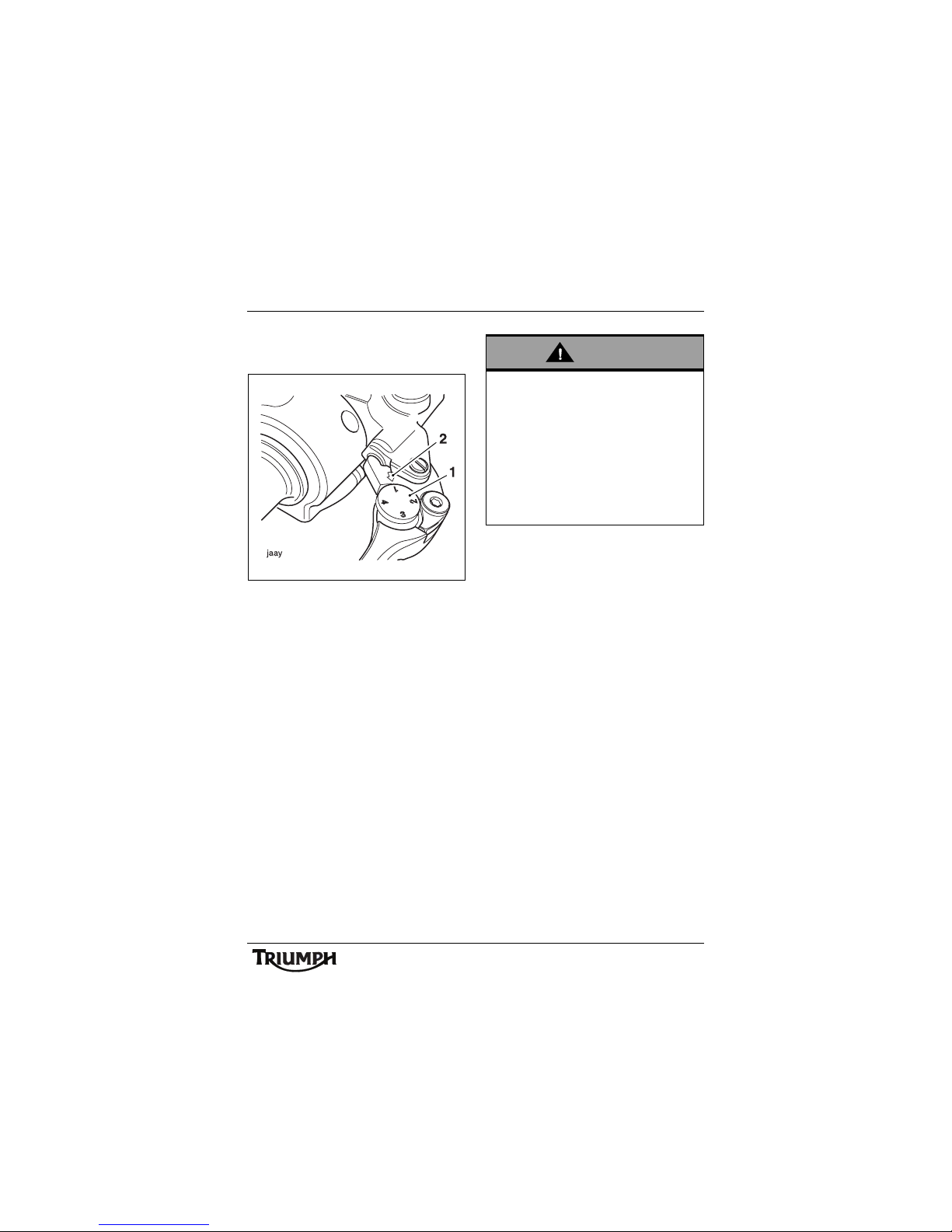
Brake and Clutch Lever
Adjusters
1. Adjuster wheel
2. Triangular mark
An adjuster is fitted to both the front brake
and clutch levers. The adjusters allow the
distance from the handlebar to the levers to
be changed to one of four positions, to suit
the span of the operator's hands.
To adjust the levers, push each lever forward
and turn the adjuster wheel to align one of
the numbered positions with the triangular
mark on the lever holder.
The distance from the handlebar grip to the
released lever is shortest when set to number
four and longest when set to number one.
Warning
Do not attempt to adjust the levers with the
motorcycle in motion as this may lead to
loss of motorcycle control and an accident.
After adjusting the levers, operate the
motorcycle in an area free from traffic to
gain familiarity with the new lever setting.
Do not loan your motorcycle to anyone as
they may change the lever setting from the
one you are familiar with causing loss of
control or an accident.
30
General Information
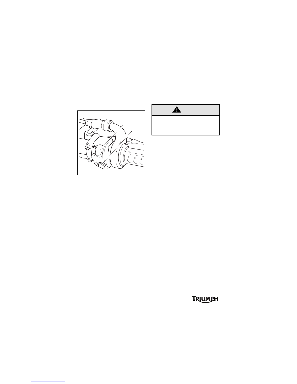
Right Handlebar Switches
1. Engine stop switch
2. Starter button
Engine Stop Switch
In addition to the ignition switch being turned
to the ON position, the engine stop switch
must be in the RUN position for the
motorcycle to operate.
The engine stop switch is for emergency use.
If an emergency arises which requires the
engine to be stopped, move the engine stop
switch to the STOP position.
Note:
• Although the engine stop switch
stops the engine, it does not turn
off all the electrical circuits and
may cause difficulty in restarting
the engine due to a discharged
battery. Ordinarily, only the
ignition switch should be used to
stop the engine.
Starter Button
The starter button operates the electric
starter. For the starter to operate, the clutch
lever must be pulled to the handlebar.
Note:
• Even if the clutch lever is pulled to
the handlebar, the starter will not
operate if the side stand is down
and a gear is engaged.
ccmm
2
1
Caution
Do not leave the ignition switch in the ON
position unless the engine is running as
this may cause damage to electrical
components and will discharge the battery.
 Loading...