

Triumph Spitfire MK3 Handbook


Introduction
DESIGNED AND BUILD to give long and consistent trouble-free service, your Spitfire
Mk3 also embodies many safety features, the very presence of which will add to your
confidence.
Read carefully the contents of this book which gives, in the simplest possible terms,
information vital to the proper operation, care and regular maintenance of the car.
Should you be unable, or prefer not to carry out the various adjustments and the regular
maintenance operations described herein, please make use of the Maintenance Voucher
Scheme which is fully described in a separate booklet supplied with the car

Important
In all communications relating
to Service or Spares, please
quote the Commission Number
(Chassis Number) Paint and
Trim Numbers
LOCATION OF COMMISSION AND UNIT NUMBERS
Commission, Paint and Trim Numbers-On L.H. Scuttle Side Panel (May
be seen by lifting the bonnet)
Engine Number-On L.H. side of Cylinder Block
Gearbox Number-On R.H. side of Clutch Housing Flange
Rear Axle Number-On Hypoid Housing Flange
Note: L.H. and R.H. refers to Left-hand and Right-hand side of the
vehicle from the driving position.
STANPART
Spare Parts Service
Replacement parts are not supplied from the factory direct to the general public, but are directed through Distributors who, in turn, supply their Dealers.
Genuine spare parts are marketed under the trade mark "Stanpart" and carry the same guarantee as the original part. The tame high quality material is used and
the strictest accuracy maintained during manufacture. You are advised, therefore, to insist on the use of these parts should replacements be necessary.
Remember, parts which do not carry the trade mark "Stanpart" will invalidate the guarantee if fitted to your vehicle.
The descriptions and illustrations appearing in this book are not binding. The MANUFACTURER, therefore, reserves the right - whilst retaining the basic
features of the Models herein described and illustrated - to make at any time, without necessarily bringing this book up-to-date, any alteration to units, parts or
accessories deemed convenient for improvement or for any manufacturing or commercial reason.

List
of
Sections
Introduction .................................................…..
Location of Unit Numbers .....................…........
Controls, Instruments and Indicators .....…........
Overdrive ......................................................….
Safety Harness Page .....................................….
Seats.............................................……….…….
Locks and Keys......................................………
Soft Top .............................................…..……..
Hard Top ......................................................…..
Wheels and Tyres …................................……..
Driving from New ........................................….
Care of Bodywork ........................................….
Cooling System ............................................….
Electrical System ..........................................….
Bulb Chart .............…........................................
Routine Servicing ....…......................................
Running Adjustments .…...................................
Recommended Lubricant…...............................
Lubrication Chart ..............................................
Lubrication Summary .......................................
Index .................................................................
Page
3
4
6
12
13
14
15
17
20
21
26
28
29
32
41
46
60
72
73
74
77
CONTROLS, INSTRUMENTS AND INDICATORS – RIGHT-HAND STEERING
6
CONTROLS, INSTRUMENTS AND INDICATORS – LEFT-HAND STEERING
7
CONTROLS, INSTRUMENTS AND INDICATORS
8
CONTROLS, INSTRUMENTS AND INDICATORS
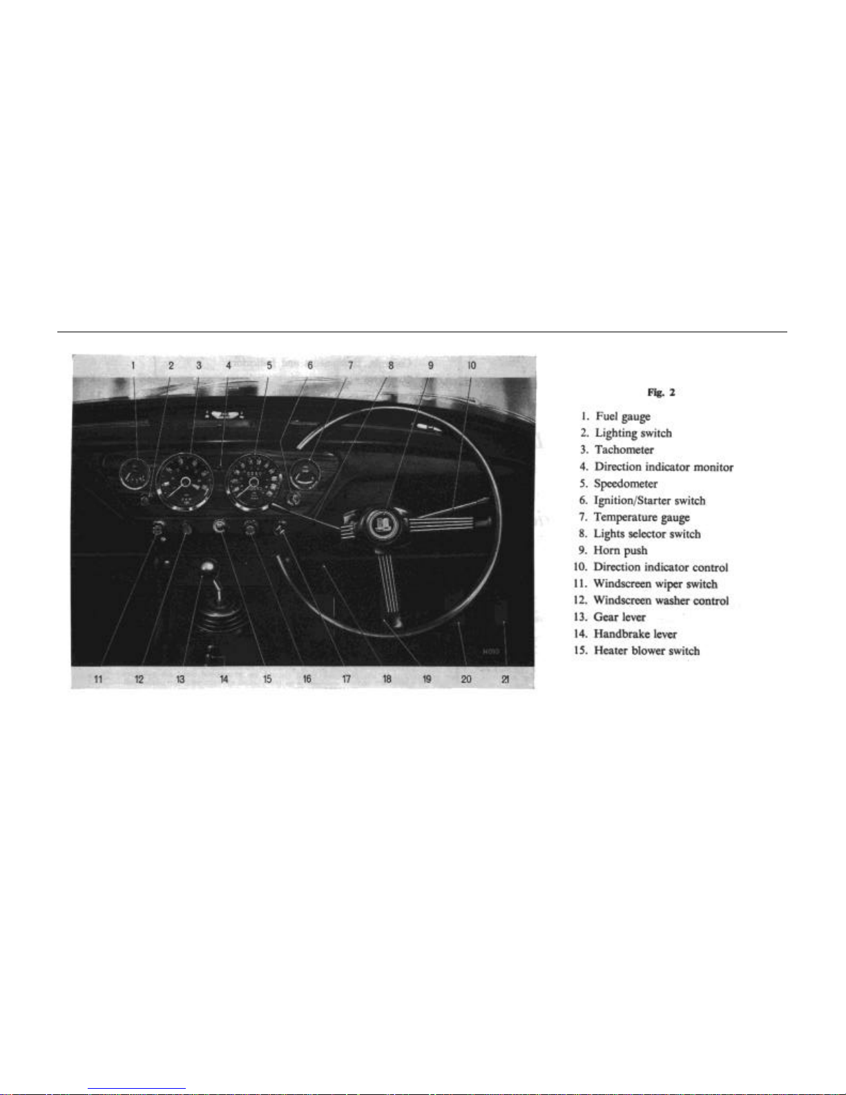
The controls, instruments and indicators shown on Figs. 2 to 8 and described in the following pages are positioned within easy reach of
the driver to afford maximum ease of operation and minimum distraction. The bracketed figures in the text cross-refer with the key on pages
6 and 7
Fuel Gauge (1)
The fuel gauge indicates the approximate contents of the fuel
tank. When the ignition is switched on, the needle moves slowly
across its scale taking up to one minute to reach a steady reading,
which it will maintain, regardless of vehicle movement, until the
fuel level is lowered or the ignition is switched off.
Lighting Switch (2)
Pull to first position to operate the driving lamps; pull to second
position to illuminate the instruments. Refer to 8 below
Tachometer (3)
The tachometer indicates the engine speed in revolutions per
minute and is calibrated in divisions of 500 extending to 6,500. The
speed range within the coloured segment is subject to the
Recommended Speed Limits mentioned on page 27.
Direction Indicator Monitor (4)
The green monitor light glows intermittently when the ignition
is switched on and the direction indicator control is operated.
Should the light fail to operate when the control is operated, a
broken filament is indicated in the front or rear flasher bulbs
at the side corresponding to non-operation of the monitor or a
broken filament in the monitor lamp.
Speedometer (5)
Additional to indicating the road speed of the vehicle in miles
and kilometres per hour, the instrument shown on Fig. 3 combines
the indicators and warning devices (22 to 26, see Fig. 7).
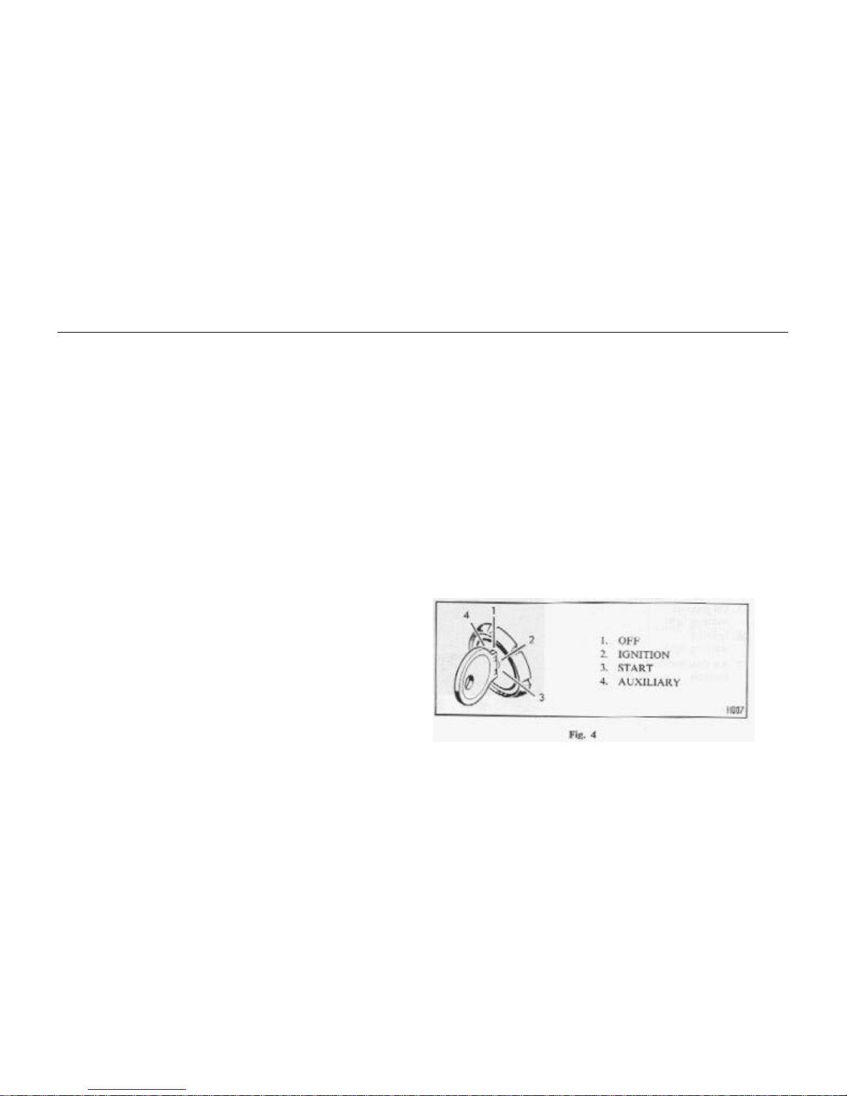
Ignition/Starter Switch (6)

CONTROL, INSTRUMENTS AND IDICATORS
9
The combined ignition and starter switch, Fig. 4, is operated by the
key used for locking the driver's door. The switch has four positions:
4, auxiliary; 1, off (in which position the key may be withdrawn); 2,
ignition; 3, start.
With the key in the "off" position, turn the key clockwise to
switch on the ignition and auxiliary circuits.
To operate the starter motor turn the key clockwise against
spring pressure and when the engine fires release the key which will
return to the ignition position. If the engine fails to start, wait until
the starter motor comes to rest before returning the key to the start
position.
Turning the key anti-clockwise to the auxiliary position permits
the use of a radio when the vehicle is stationary and the ignition is
switched off.
Water Temperature Gauge (7)
Normal operating temperature is reached when the needle
registers in the central sector of the dial. Should the needle reach the
highest mark, stop the engine immediately, allow it to cool and
check the level of the coolant in the radiator. Refer to page 47
Lights Selector Switch (8)
Move the switch lever to the upper position to operate side
lamps only; move the lever to the central position for high beam,
when the high beam is operating a monitor light contained in the
speedometer unit glows blue; move the lever to the lower position
for dipped headlights. Lifting the selector lever towards the steering
wheel flashes the headlight main beams.
Horn Push (9)
Press to operate.
Direction Indicator Control (10)
Move the control lever counter-clockwise to operate the lefthand flashing indicators and clockwise to operate the right-hand
indicators.
Windscreen Wiper Switch (11)
Pull the switch knob to operate the wipers, and push to switch
them off, when the wipers will automatically return to the parked
position at the base of the windscreen. The wipers operate only
when the ignition is switched on.
Windscreen Washer (12)
The windscreen washer control should be used in conjunction
with the windscreen wiper. Operate by pushing the control to spray
clean fluid onto the screen as the wiper blades disperse the mud. If
the washer has remained unused for some time, depress the control a
few times to charge the system.
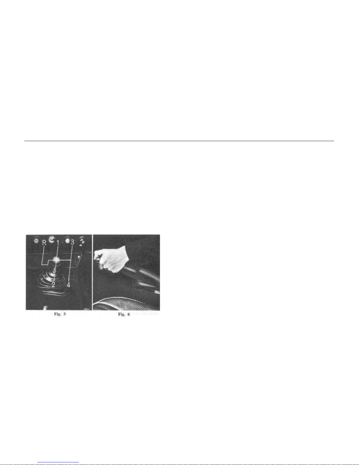
Gear Lever (13)
Moving the gear lever from neutral, the gear positions are obtained
as follows:
CONTROLS, INSTRUMENTS AND INDICATORS
10
1st .. .. Move the lever left and forward
2
nd ..
.. Move the lever left and rearward
3rd .. Move the lever right and forward
4th (Top) .. Move the lever right and rearward
Reverse .. Press the lever downwards, move it to
the extreme left and forward. Engage
only when the vehicle is stationary
Always select neutral before starting the engine.
Handbrake Lever (14)
To apply the rear wheel brakes, pull the handbrake lever
upwards. It is retained in position by a ratchet and pawl.
Release the handbrake by pulling it slightly upwards before
depressing the button to free the pawl; then allow the lever to move
downwards to the "off" position.
Heater Blower Switch (15)
The blower motor, which is controlled by a toggle switch, may
be used to boost the flow of hot or cold air. Move the switch left to
operate the motor and right to switch off.
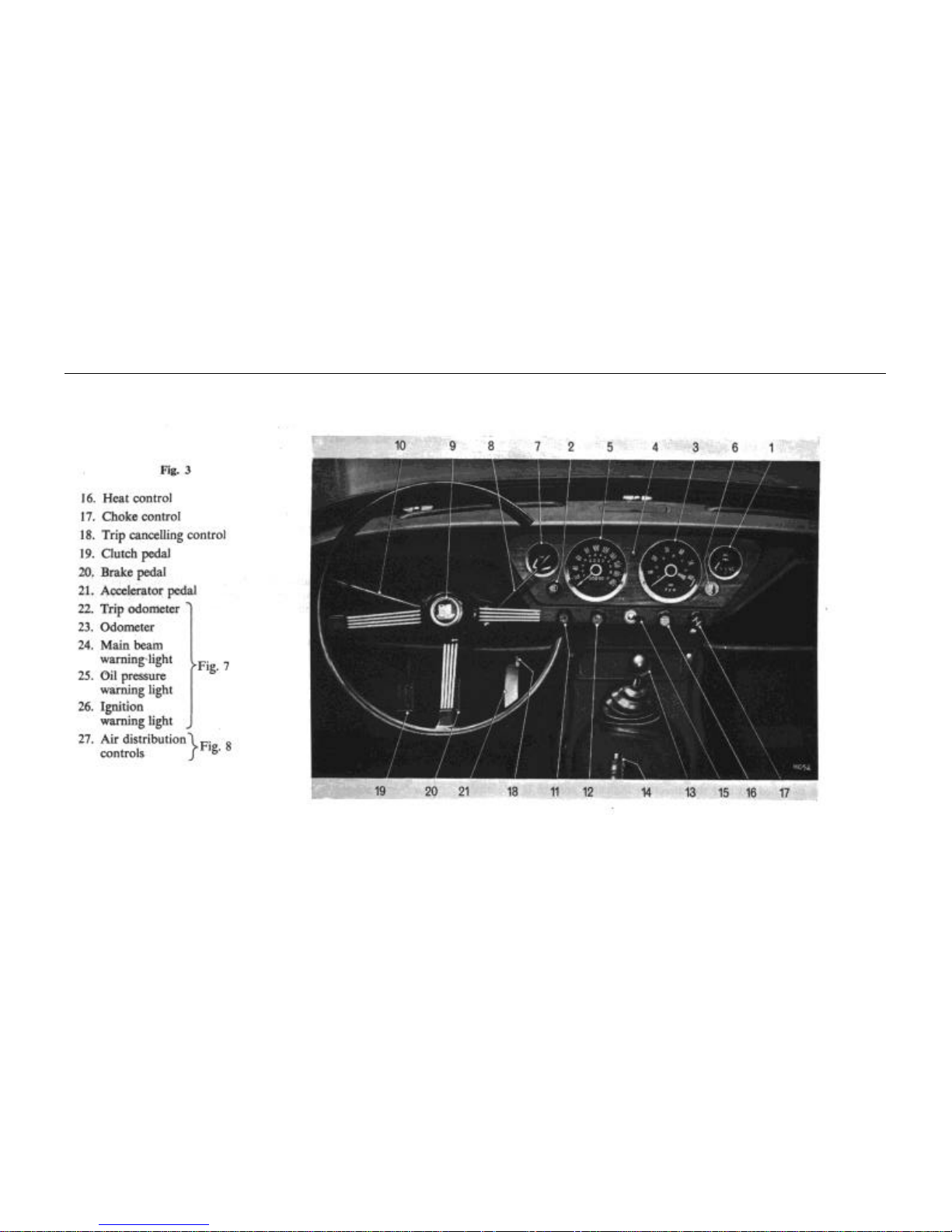
Heat Control (16)
The heat control operates a water valve which regulates the flow
of water through the heater unit. The control may be set at any
intermediate position as required. The water valve is closed when
the control is pushed in; maximum heat is available when the
control is pulled out.
Choke Control (17)
The choke control is used to enrich the fuel mixture for easy
starting from cold. Twist the control clockwise before pulling and
turn it anti-clockwise to lock in the desired position. (See "Starting
from cold" on page 26).
Clutch, Brake and Accelerator Pedals (19, 20, 21)
These are conventional items that need no further explanation,
except to remind the driver that needless wear of the clutch
mechanism will result from driving with the left foot resting on the
pedal.
CONTROL, INSTRUMENTS AND IDICATORS
11
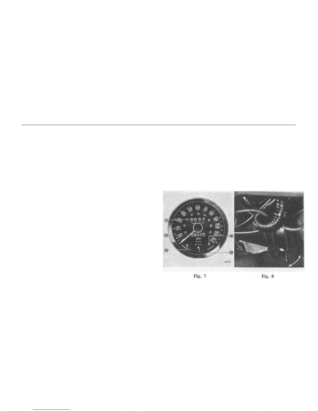
Trip Odometer (22, Fig. 7)
The figures within the aperture above the centre of the dial may
be used to record the distance of each journey, providing that the
figures are initially set at zero. This is achieved by turning clockwise
the knob (18), Figs. 2 and 3, which extends downwards from behind
the instrument.
Odometer (23, Fig. 7)
The figures within the aperture below the centre of the dial show
the total mileage of the vehicle and may be used as a guide for
periodic lubrication and maintenance.
Main Beam Warning Light (24, Fig. 7)
The indicator at the bottom left-hand side of the dial glows blue
when the headlamp main beams are selected and is extinguished
when the headlamps are "dipped".
Oil Pressure Warning Light (25, Fig. 7)
The centre indicator at the bottom of the dial glows green when
the ignition is switched on and is extinguished when the engine runs
in excess of idling speed. Should the tight remain on at normal
running speeds, stop the engine and check the level of oil in the
engine sump. If this is satisfactory, have the lubrication system
checked immediately.
Ignition Warning Light (26, Fig. 7)
The indicator at the bottom right-hand side of the dial glows red
when the ignition is switched on and is extinguished when the
engine is accelerated. Should the red light remain on whilst driving,
a fault is indicated in the battery charging system which should be
rectified without delay.
Air Distribution Controls (27, Fig. 8)
The distribution of hot or cold air is controlled by two flap
valves located under the facia and near to the feet of the driver and
passenger. When the flaps are closed, maximum air flow is directed
to the windscreen for demisting or de-frosting. Fully open flaps
allow maximum air flow to the area around the feet.
OVERDRIVE
12
OVERDRIVE (optional)
An overdrive unit serves as a convenient method of providing, at
will, a numerically lower overall gear ratio to reduce engine speed
and to improve fuel economy.
The Laycock de Normanville overdrive unit incorporates an
epicyclic gear train which is engaged, to give overdrive condition,
by a cone clutch moving under the influence of hydraulic pressure
generated by a small piston pump. When pressure is released via a
control valve, the clutch is returned and held in direct drive by
compression springs. A uni-directional roller clutch enables
the change into, or out of, overdrive to he made when transmitting
full power without loss of road speed.
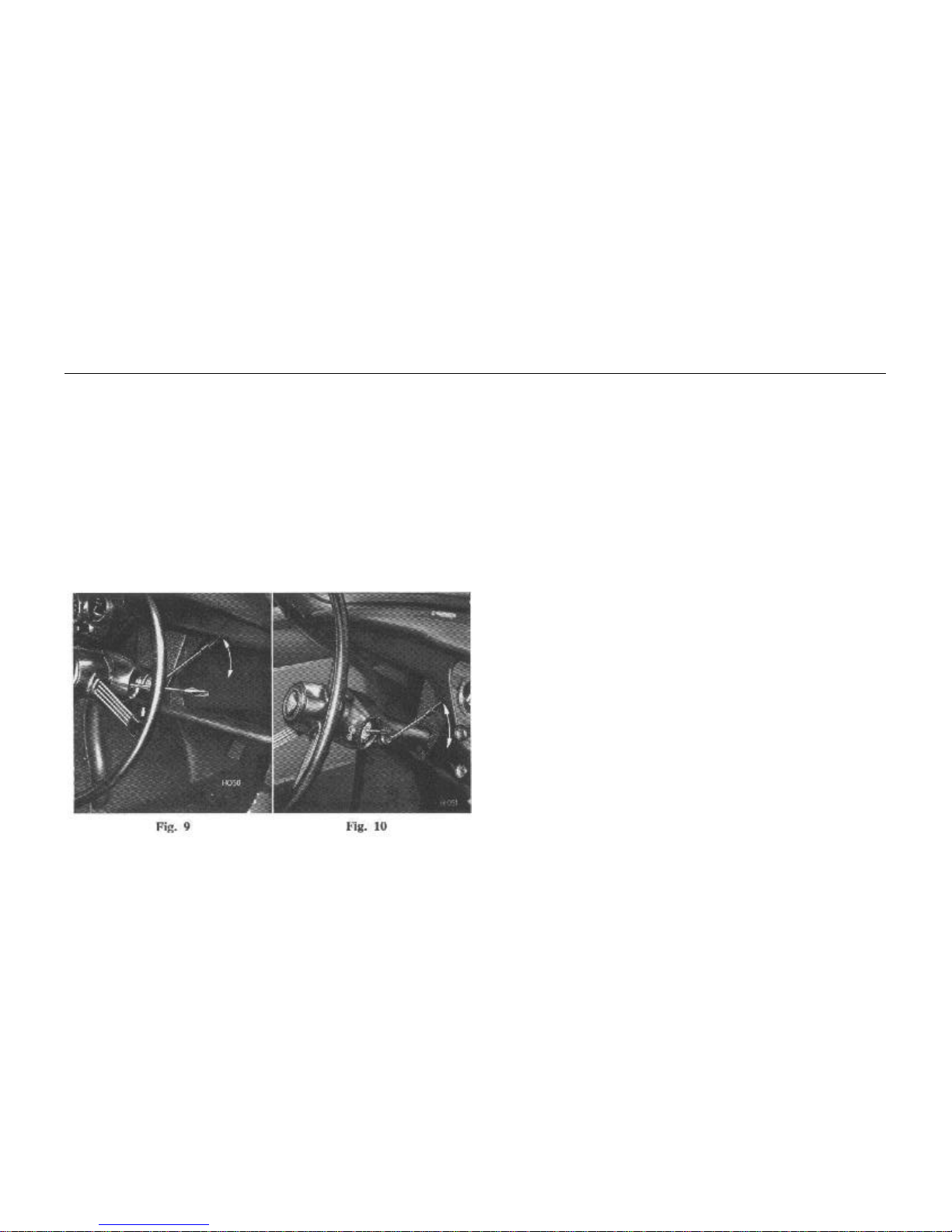
The hydraulic control valve is linked to an electro-magnetic
solenoid, which is operated via a relay by a two-position switch
mounted on the steering column (Figs. 9 and 10).
Greatest benefit will accrue from judicious use of the overdrive,
the governing factor being that the vehicle continues to run easily
without sign of engine labouring, combined with the minimum
amount of throttle opening necessary to maintain this condition.
Maximum disengagement speed: 4,800 r.p.m.
The preceding disengagement speed corresponds approximately
to peak revolutions in normal gear.
Disengagement of the overdrive at a speed higher than stated
may cause damage from 'over-revving".
Operation
Move the selector switch down to engage overdrive and up to
release it.
Lubrication
The same oil is used for both the overdrive unit and the gearbox,
an internal oil transfer hole allowing the flow from the gearbox
into the overdrive unit until a common level is attained.
Periodically check and if necessary top up the gearboxoverdrive unit oil level via the gearbox filler orifice. (Refer to
page 51).
SAFETY HARNESS
13
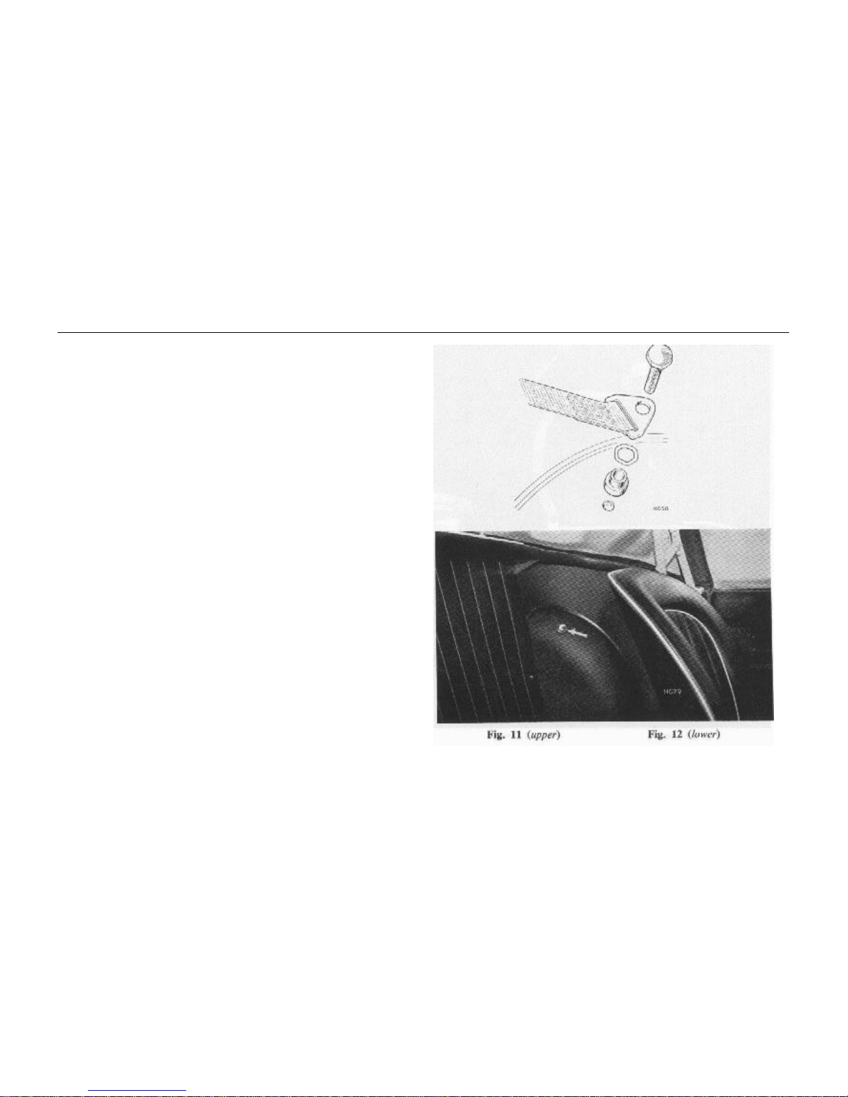
SAFETY HARNESS (optional)
Provision is made for the use of three-point attachment safety belts;
anchorage points are built into the vehicle and are
shown on Figs. 12 and 13.
Fitting the Harness
Remove the shoulder strap anchor bolt, crimped washer and
collar from each wheelarch, pass the bolt through the strap
attachment, fit the crimped washer and collar, as shown on Fig. 11,
and refit to the vehicle.
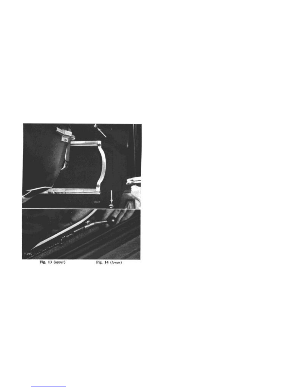
By means of the latched hooks fit the lap strap to the eye bolts, Fig.
13. The shoulder strap will have a half twist when fitted to the
wheelarch, this is the correct position.
Using the Harness
Pass the buckle end of the belt around the hips, and fasten the
belt by pushing the locking plate into positive engagement with the
buckle. This is denoted by a "click". To release the harness depress
the centre panel.
SAFETY HARNESS AND SEATS
14
Harness Adjustment
The belt should he adjusted so that the hand will pass between
the strap and the chest. The lap strap should be reasonably tight and
the buckle must rest on the hip nearer the centre of the vehicle.
Adjustment to lower half of belt:
Relieve any tension on the belt and pull the belt over the roller
in the buckle, the roller has a self-locking action and once the belt
has been adjusted it will lock the belt in position.
Adjustment to upper half of belt:
Pull the grey slide on the lower part of the lap strap upwards to
shorten and downwards to lengthen.
Cleaning
Badly stained safety belts may be dry cleaned. The cleaner
should be advised of the nature of staining. Belts subjected to
normal soiling may be cleaned with soap, or proprietary brand
detergents dissolved in hot water.
Seat Adjustment (Fig. 14)
The driver's and passenger's seats are adjustable for leg reach by
lifting the lever at the outer side of each seat and sliding the seat to
the desired position. Allow the lever to re-engage in the nearest
adjustment notch. Both seats will tilt forward to provide access to
the rear compartment, when the clip at the base of the seat back is
released.
LOCKS AND KEYS
15
LOCKS AND KEYS
The vehicle is provided with two sets of keys, the spare set
being obtained from the selling dealer. One key is used to operate
the ignition, the other is for the luggage compartment and door
locks.
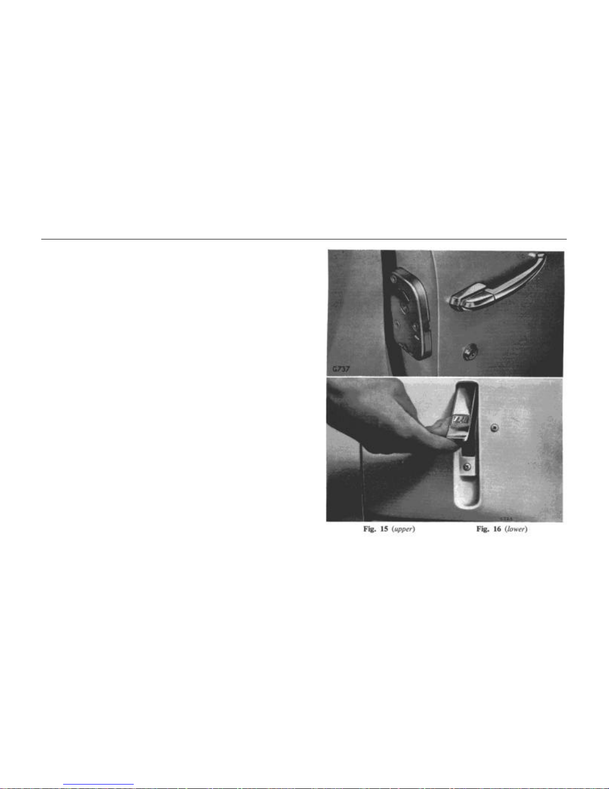
Door Locks (Fig. 15)
"Anti-burst" locks are fitted to both doors and are operated by a
pushbutton on the outside or by pulling the remote-control lever on
the inside. To lock the door from the inside, push the lever forwards;
to lock the door from the outside, insert the key and turn it a quarter
turn away from the shut face. The key will return under the
influence of spring loading to a vertical position when it may be
withdrawn.
Lubrication
One a month, particularly during freezing weather, apply a few
drops of thin machine oil into the latch and key slots.
IMPORTANT. Do not apply grease to the lock cylinders.
Bonnet Lock (Fig. 16)
The bonnet is opened by raising, as far as possible, a lever on
each side to release the catches and lifting the bonnet at its rear.
LOCKS AND KEYS
16
This permits the bonnet to pivot on its anchorage to a vertical
position where it is held by a folding strut.
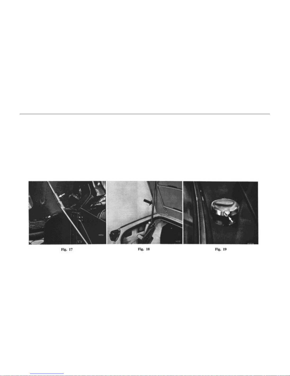
To close the bonnet, pull the centre of the strut (arrowed Fig. 17)
simultaneously supporting and lowering the bonnet. Press each lever
flush with the side of the bonnet to lock.
Luggage Compartment Lid (Fig. 18)
To open the luggage compartment lid, turn the unlocked
handle counter-clockwise to a vertical position and raise the lid to its
limit before lowering it on to the telescopic support.
Close the lid by raising it slightly to release the catch in the
telescopic support, lower, and turn the handle which may be locked
by turning the key a half turn counter-clockwise.
Fuel Filler Cap (Fig. 19)
The fuel filler cap, located forward of the luggage locker lid, is
opened by depressing a small lever at the side of the cap. Press the
cap to close.
SOFT TOP
17
SOFT TOP
The soft top, which is made from P.V.C. material, is supported by a
hinged frame. The assembly folds down into the back of the car and
is retained in place by a cover.
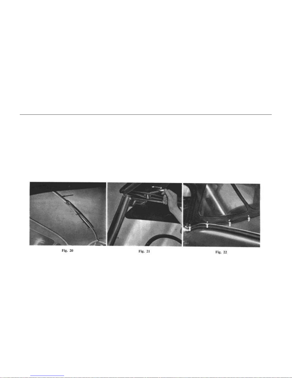
Raising the Soft Top
Unfasten and remove the hood cover. Fold the sides of the hood
fabric outwards and pull the fabric rearwards over the luggage
compartment lid. Lifting the front hoodrail, raise the assembly
sufficiently to allow the fabric to lie evenly over the frame. Secure
the fasteners (four each side, Fig. 22) to the body. Locate the front
hoodrail on the windscreen header rail and turn the levers (Fig. 21)
inwards. Knock the second hoodstick
SOFT TOP
18
arrowed Fig. 20) forwards as far as possible, and secure the
fasteners (Fig. 20).
Lowering the Soft Top
Release the fasteners securing the fabric to the second hoodstick (Fig. 20). Release the toggles (Fig. 21) and the fasteners (four
each side, Fig. 22) securing the edges of the hood to the body.
Push the front hoodrail rearwards and slightly upwards while
knocking the second hoodstick (arrowed Fig. 20) rearwards, until
the assembly begins to fold. DO NOT PULL the second hood-
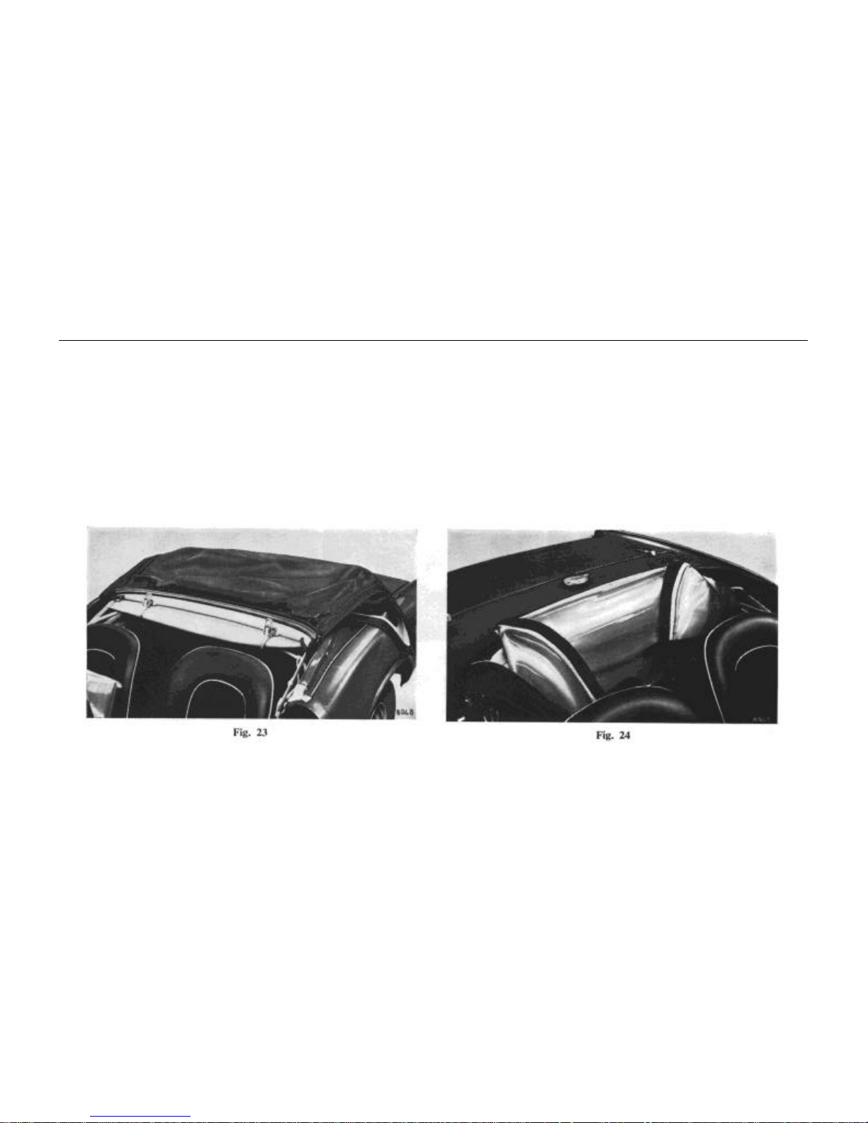
stick downwards. Continue lowering the frame and pull the
fabric flat over the luggage compartment lid (Fig. 23). Fold the
fabric forwards over the hoodsticks and turn the sides inwards
(Fig. 24). Ensure that the Vybak windows are free from distortion
and that the hood fabric is not trapped by the hoodsticks.
SOFT TOP
19
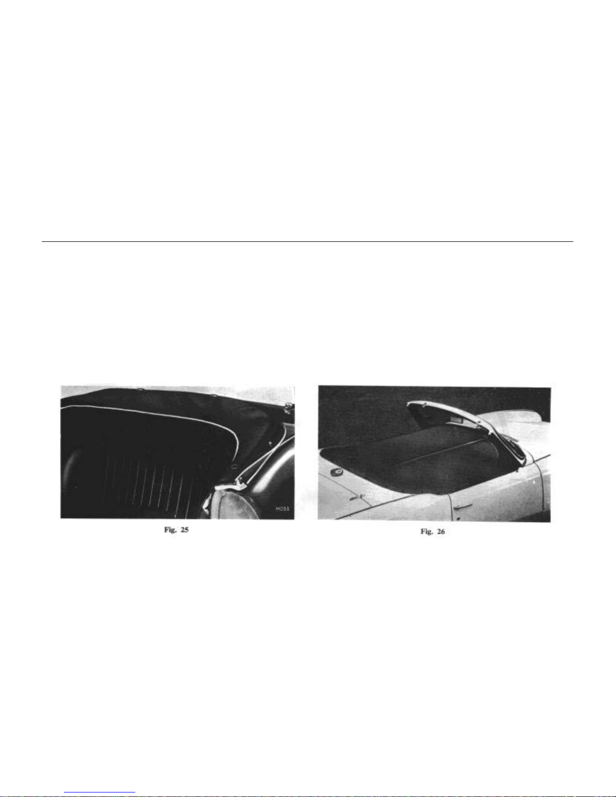
Retain the hood in position with the cover provided (Fig. 25) as
follows:
Attach the cover to the outer fasteners and continue working
towards the centre. Attach the inner pillar fasteners and hook the
three straps under the bottom hoodstick.
Tonneau Cover (Optional) (Fig. 26)
The tonneau cover provides weather protection for the vehicle
interior when the soft top is lowered. It incorporates press-studs
for securing to the car and a zip fastener which permits access to
either or both of the front seats.
HARD TOP
20
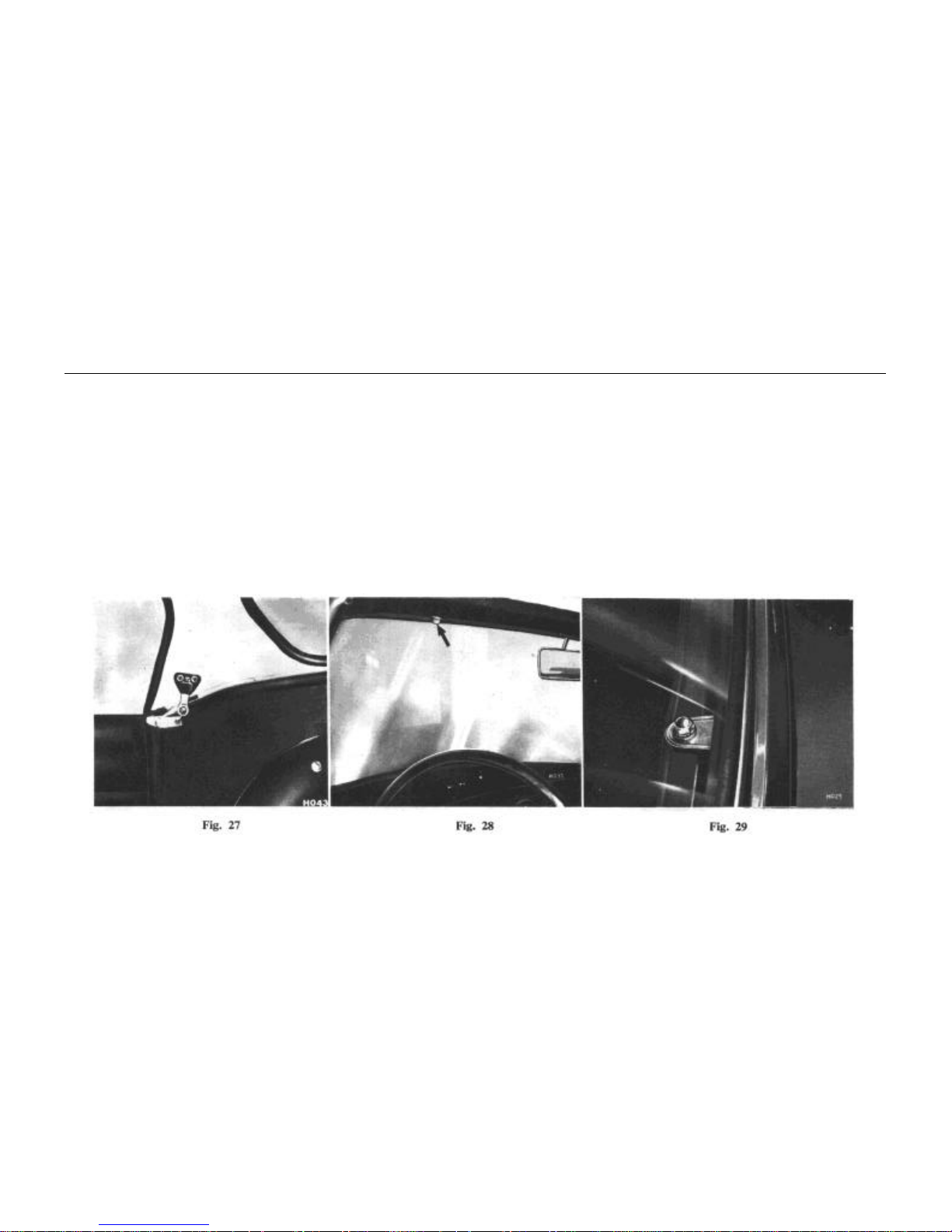
HARD TOP (Optional)
The vehicle may be used as an open sports car by removing the
hard top assembly as follows:
Unscrew the domed-head bolts securing the hard top side brackets
to the door pillar brackets (Fig. 27).
Remove the domed-head bolts and washers securing the
hard-top to the windscreen header rail (Fig. 28) and the rear deck
panel (Fig. 29).
With the aid of a second operator lift off the hard top assembly
To refit the hard top, reverse the foregoing procedure.
WHEELS AND TYRES
21
WHEELS AND TYRES
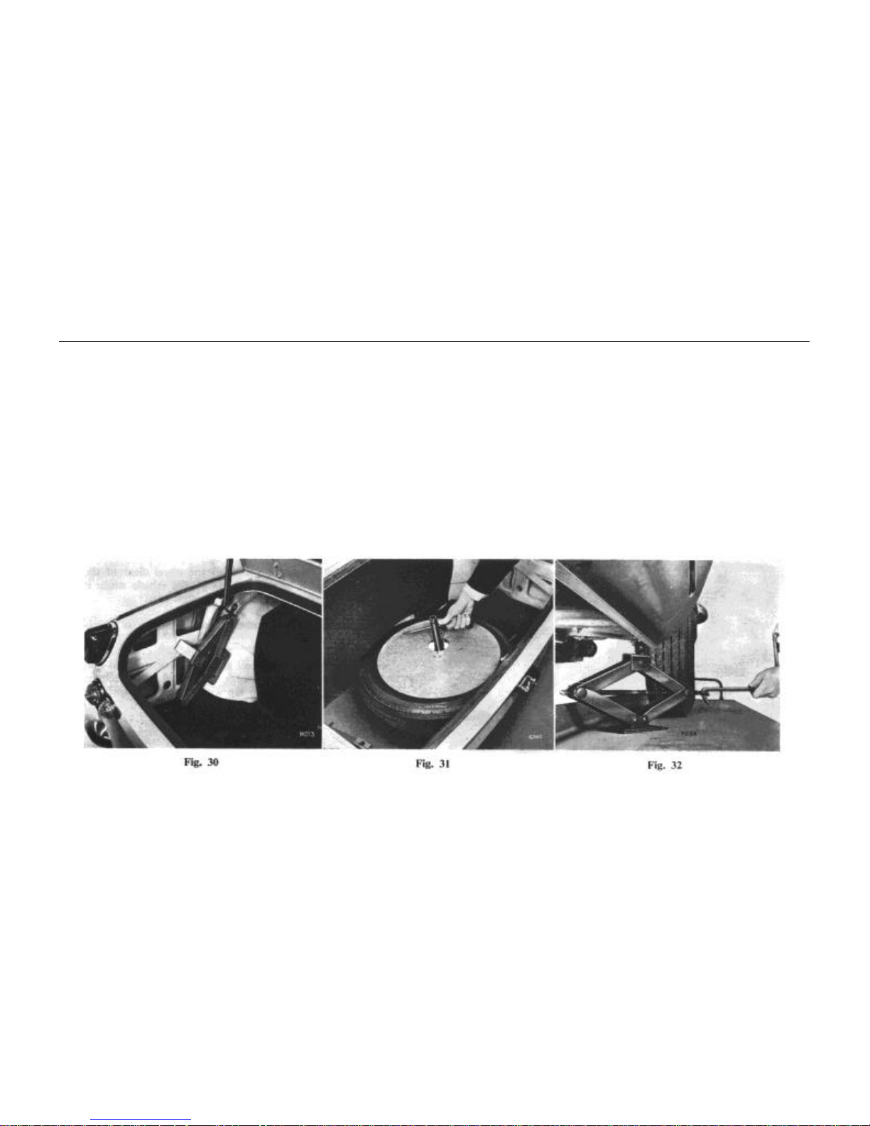
Spare Wheel and Lifting Jack
The tools and spare wheel are housed in the luggage
compartment as shown on Figs. 30 and 31.
NOTE. A variant of the jack illustrated may be provided.
To remove the spare wheel, lift off the cover and unscrew the
retaining nut (Fig. 31).
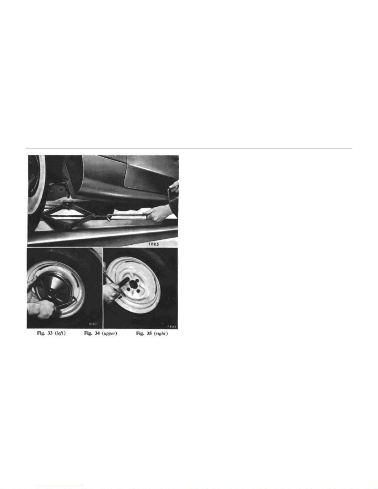
The Jack (Figs. 32 and 33)
Locate the nut of the fixing bolts (rearwards of the front wheel
and forwards of the rear wheel) in the head of the jack for safety
when lifting a wheel.
Assemble the handle into the jack and turn it to lift the required
wheel from the ground.
WHEELS AND TYRES
22
Wheel Changing Procedure (Pressed Steel Wheels)
1. Firmly apply the hand brake and chock the wheel diagonally
opposite the one being lifted.
2. Remove the spare wheel from the luggage compartment and
make sure that its tyre pressure is correct.
3. Using the special lever provided in the tool kit, lever off the
nave plate as shown and slightly loosen the wheel nuts.
4. Place the jack in position and lift the wheel clear of the
ground. Should it be necessary to lift the vehicle whilst it is
on sloping ground, exercise the greatest care.
5. Completely remove the wheel nuts, exchange the road
wheels and replace the nuts.
6. Lower the jack, give the wheel nuts a final tighten and refit
the nave plate by placing its edge over the wheel projections
and giving the plate a sharp tap with the hand to spring it
into position.
WHEELS AND TYRES
23
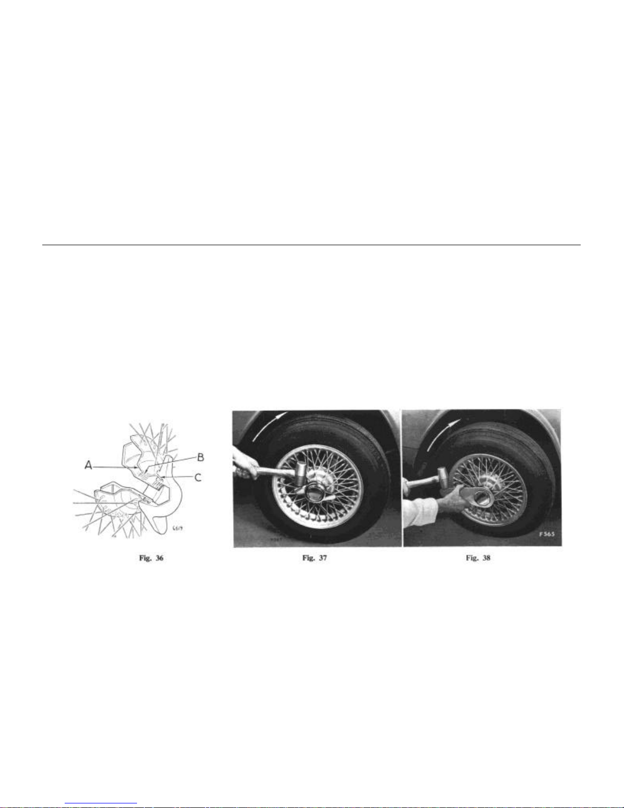
Wire Spoke 'Wheels (Optional) (Fig. 36)
Before fitting a wheel, check that the adaptor taper (A) and its
mating wheel hub taper are undamaged and that each presents a
clean painted surface. DO NOT GREASE THESE SURFACES.
Ensure that the following are undamaged, cleaned and coated with
grease: splines (B), screw threads, wheel hub outer taper (C) and the
large wheel nut tapers.
Slide the wheel on to the adaptor and while pushing against the
wheel hub centre to maintain concentric location, simultaneously
screw on the retaining nut by hand until the wheel is felt to seat on
the adaptor taper.
Restraining the wheel with one hand, continue tightening by
striking the spanner or the ears of the nut with a soft faced hammer.
Lower the wheel to the ground and finally tighten. (Figs. 37 and 38).
Check that each wheel retaining nut tightens in the opposite
direction to the wheel rotation. The foregoing instructions apply
each time a wheel is removed and replaced.
IMPORTANT. Splined adaptors must be fitted to the correct
side of the vehicle left-hand threaded adaptors to the right-hand side
and right-hand threaded adaptors to the left-hand side (as viewed
from the driver's seat).
WHEELS AND TYRES
24
Wheel Alignment
The correct front wheel alignment is 1/16" (1.6 mm.) to 1/8"
(3.2 mm.) toe-in (kerb condition). Excessive misalignment caused
by kerb impact or other accidental damage will result in severe tyre
wear and faulty steering.
Wheel Run-out and Ovality
The maximum tolerances for both run-out and ovality are as
follows:
Press steel wheels .. .. .. 0.070" (0.l8mm.)
Wire spoke wheels .. .. .. 0.060" (0.l5 mm.)
Excessive run-out and ovality will result in severe tyre wear and
faulty steering.
Tyre Wear
When new tyres are required it is essential to fit those of the
same type. The characteristics of tyres vary considerably and,
therefore, all four tyres must be of the same type.
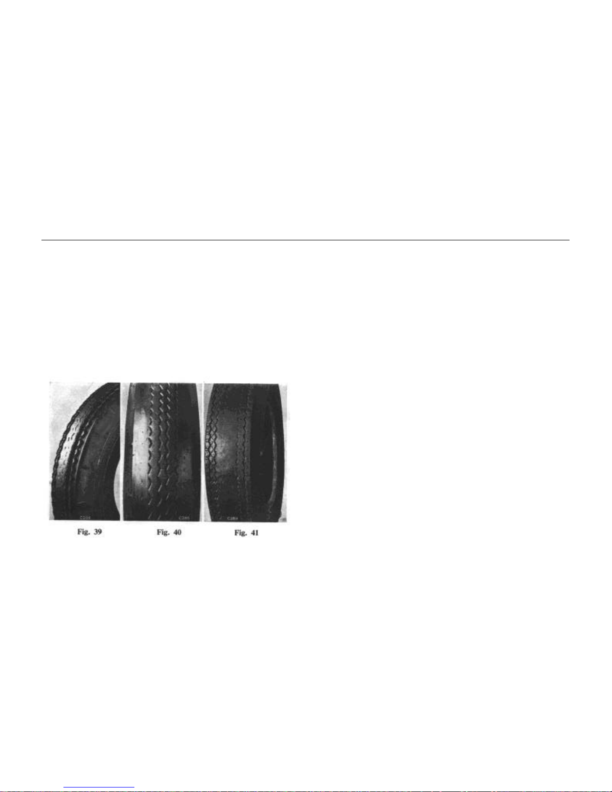
Occasionally remove flints and other road matter from the treads
and examine the tyres for sharp fins, flats and other irregularities.
An upstanding sharp fin on the edge of each pattern rib is a sure sign
of road wheel misalignment (Fig. 39).
Fins on the inside of the pattern ribs indicate toe-in. Fins on the
outside edges indicate toe-out. Sharp pattern edges may also be
caused by road camber, even when road alignment is correct. In
such cases, it is better to make sure by having the track checked with
an alignment gauge.
"Spotty" tread wear or flats, can result from grabbing brakes or
unbalanced wheel assemblies. Your Standard-Triumph Dealer will
check the action of the brakes and re-balance the tyres if required.
The original degree of balance is not necessarily maintained, and it
may be affected by uneven tread wear, by repairs, by tyre removal
and refitting, or by wheel damage and eccentricities. The vehicle
may also become more sensitive to unbalance due to normal wear of
moving parts.
 Loading...