

Page 1

Service Manual - Scrambler 1200
XC
Introduction
Introduction
This manual is designed primarily for use by trained technicians in a properly
equipped workshop. However, it contains enough detail and basic information to
make it us eful to the owner who desires to perform his own basic maintenance and
repair work. The work can only be carried out if the owner has the necessary hand
and special service tools to complete the job.
A basic knowledge of mechanics , including the proper use of tools and workshop
procedures is necess ary in order to carry out maintenance and repair work
satis factorily. Whenever the owner has ins ufficient experience or doubts regarding his
ability to do the work, an authoris ed Trium ph dealer mus t undertake all adjus tments,
maintenance, and repair work.
In order to perform the work efficiently and to avoid costly m istakes, read the text and
thoroughly familiarise yourself with procedures before starting work.
All work should be performed with great care and in a clean working area with
adequate lighting.
Always us e the correct special service tools or equipment specified. Under no
circum stances use makeshift tools or equipm ent since the use of subs titutes may
adversely affect safe operation.
Where accurate measurements are required, they can only be made using
calibrated, precis ion ins trum ents.
For the duration of the warranty period, an authorised Triumph dealer mus t perform
all repairs and scheduled maintenance.
To maximis e the life of your motorcycle:
Accurately follow the maintenance requirem ents of the periodic maintenance
chart in the Service Manual.
Do not allow problems to develop. Inves tigate unus ual nois es and changes in
the riding characteristics of the motorcycle. Rectify all problems as soon as
pos sible (im mediately if safety related).
Use only genuine Trium ph parts as lis ted in the electronic parts catalogue (EPC).
Follow the procedures in this manual carefully and completely. Do not take short
cuts.
Keep complete records of all maintenance and repairs with dates and any new
parts installed.
Service Manual - Scrambler 1200 XC 1 of 640
Page 2
Use only approved lubricants, as specified in the Owner's Handbook, in the
maintenance of the motorcycle.
How to use this manual
To as sis t in the us e of this manual, the section title is given at the top.
Each major section starts with a contents page, listing the inform ation contained in
the section.
The individual steps com pris ing repair operations are to be followed in the sequence
in which they appear.
Adjustment and repair operations include reference to service tool numbers and the
ass ociated illustration depicts the tool.
Where us age is not obvious , the tool is shown in us e.
Adjustment and repair operations als o include reference to wear limits, relevant data,
torque figures, specialis t information and useful assem bly details .
Warnings, Cautions and Note s
Particularly im portant information is presented in the following form:
WARNING
This warning symbol identifies special instructions or procedures which, if not
correctly followed, could result in pers onal injury, or loss of life.
CAUTION
This caution symbol identifies special instructions or procedures which, if not
strictly observed, could result in damage to or des truction of equipment.
Note
This note symbol indicates points of particular interest for more efficient and
convenient operation.
Tampering with Noise Control Syste m Prohibited
Owners are warned that the law may prohibit:
The removal or rendering inoperative by any person other than for purposes of
maintenance, repair or replacement, of any device or element of design
incorporated into any new vehicle for the purpos e of nois e control prior to its sale
or delivery to the ultimate purchaser or while it is in use; and
The use of the vehicle after such device or elem ent of design has been removed
or rendered inoperative by any pers on.
Service Manual - Scrambler 1200 XC 2 of 640
Page 3

Refe re nces
References to the left hand or right hand side given in this manual are made when
viewing the motorcycle from the rear.
Operations covered in this manual do not always include reference to testing the
motorcycle after repair. It is essential that work is ins pected and tested after
completion and, if necessary, a road test of the motorcycle is carried out particularly
where safety related items are concerned.
Dimensions
The dim ensions quoted are to des ign engineering specification with service limits
where applicable.
During the period of running-in from new, certain adjus tments may vary from the
specification figures given in this manual. These will be reset by the dealer at the 500
mile/800 km service, and thereafter should be maintained at the figures specified in
this manual.
Repairs and Replace ments
Before rem oval and disas sem bly, thoroughly clean the motorcycle. Any dirt entering
the engine or other parts will work as an abras ive and shorten the life of the
motorcycle. Particular attention should be paid when installing a new part, that any
dus t or metal filings are cleared from the immediate area.
Force
Com mon sens e should dictate how much force is necess ary in assembly and
dis ass embly. If a part seem s especially difficult to remove or install, stop and
exam ine what may be causing the problem . Never lever a com ponent as this will
caus e damage both to the component itself and to the surface being levered against.
Whenever tapping to aid removal of an item is necess ary, tap lightly using a hide or
plastic faced mallet.
Edge s
Watch for sharp edges , es pecially during engine disassem bly and assembly. Protect
the hands with industrial quality gloves.
When replacement parts are required, it is es sential that only genuine Triumph parts
are us ed.
Safety features and corrosion prevention treatments em bodied in the motorcycle may
be im paired if parts other than genuine Trium ph parts are fitted. In certain territories ,
legis lation prohibits the fitting of parts not to the manufacturer's specification.
Tightening procedure
Service Manual - Scrambler 1200 XC 3 of 640
Page 4

Generally, when ins talling a part with several bolts, nuts or screws, they should all be
started in their holes and tightened to a snug fit, evenly and in a cros s pattern. This is
to avoid distortion of the part and/or gas or oil leakage. Conversely, bolts, nuts, or
screws, should all be loosened (in sequence if specified) by about a quarter of a turn
and then rem oved.
Where there is a tightening sequence specified in this Service Manual, the bolts,
nuts, or screws must be tightened in the order and by the method indicated.
Torque wrench setting figures given in this manual must be observed. The torque
tools used must be of accurate calibration.
Torque Tolerance
Torque
Tolerance
0 Nm to 25 Nm
+/- 10%
26 Nm to 100 Nm
+ 10% -0%
101 Nm to 200 Nm
+10% -0%
Locking devices, where specified, must be fitted. If the efficiency of a locking device is
impaired during removal it must be renewed. This applies particularly to micro-
encaps ulated fixings which must always be replaced if disturbed. Where neces s ary,
the text in this manual will indicate where such a fixing is us ed.
Use of Crow Foot Spanner Adapters with Torque Wrenches
The use of a crow foot spanner adapter will effectively lengthen the lever arm of a
torque wrench. The amount of torque applied to a fas tener is increas ed as the torque
wrench lever arm is extended, therefore the torque wrench setting must be adjus ted
in order to achieve the correct tightening torque.
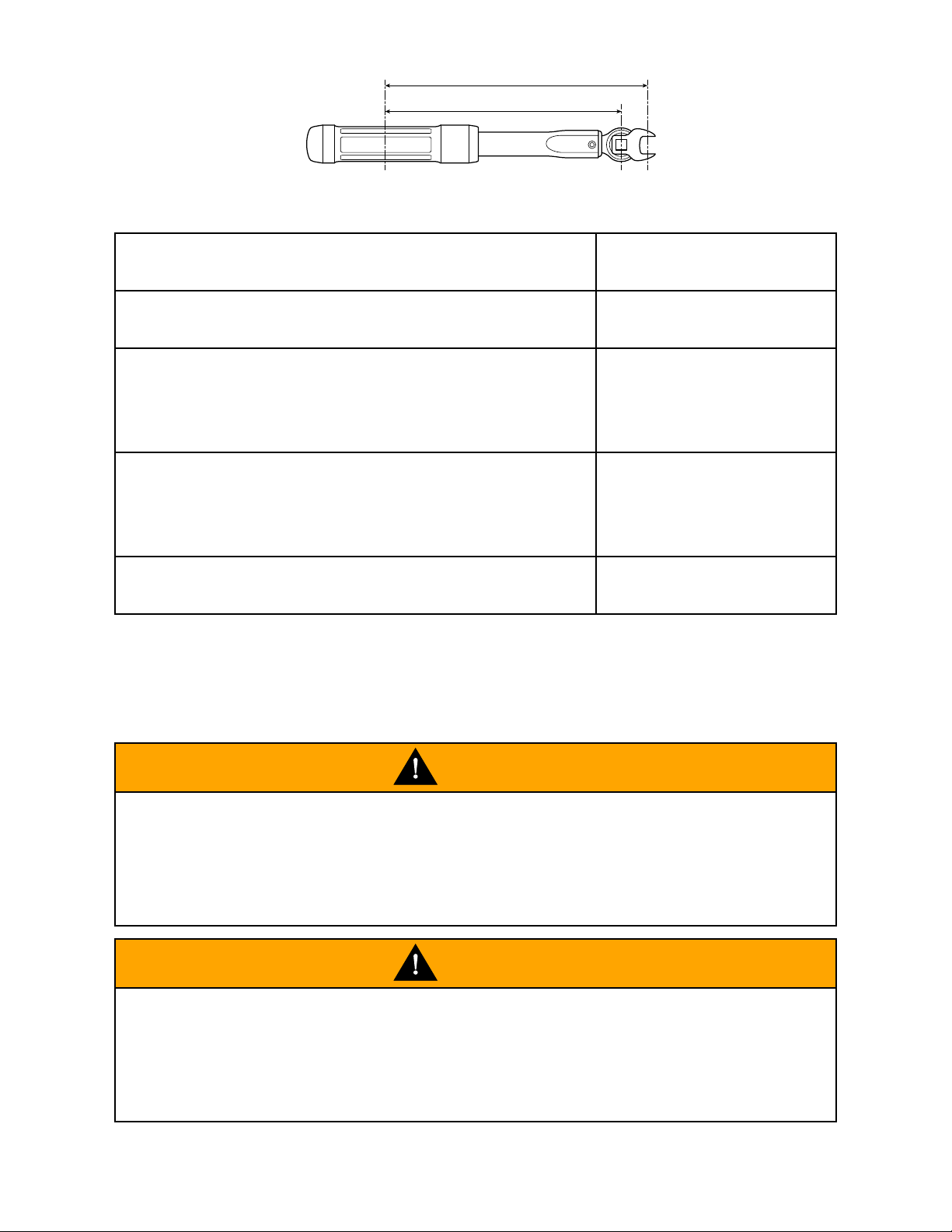
Before tightening a fixing using a crow foot spanner adapter, measure the normal
length of the torque wrench from the centre of the drive square to the centre of the
handle (dim ens ion L1). Fit the crow foot spanner adapter to the torque wrench as
shown below. Meas ure the extended length of the torque wrench from the centre of
the crow foot spanner head to the centre of the handle (dimens ion L2).
Use the following formula to calculate the correct torque wrench setting to achieve the
required tightening torque.
Note
The example shown below is calculated using a crow foot spanner measuring
25 mm from the centre of the spanner head to the centre of the drive square.
Service Manual - Scrambler 1200 XC 4 of 640
Page 5
ciyj
L2
L1
M1 = M2 x L1 / L2
Example
M2 is the required tightening torque to be applied
90 Nm
L1 is the normal length of the torque wrench,
measured from the centre of the drive square to the
centre of the handle
300 mm
L2 is the extended length of the torque wrench,
measured from the centre of the crow foot spanner
head to the centre of the handle
325 mm
M1 is the calculated torque wrench setting
83 Nm
General Information
Ignition System Safety Precautions
WARNING
The ignition sys tem produces extrem ely high voltages . Do not touch any part of the
ignition sys tem or any cables while the engine is running.
An electric shock caus ed by contact with the ignition system may lead to illness,
injury or death.
WARNING
Wearers of surgically implanted heart pacemaker devices should not be in close
proximity to ignition circuits and or diagnos tic equipment.
The ignition sys tem and any diagnostic equipm ent may interrupt the normal
operation of such devices causing illnes s or death.
Dangerous Substance s
Service Manual - Scrambler 1200 XC 5 of 640
Page 6
WARNING
Many liquids and other substances used in motor vehicles are poisonous and
should under no circumstances be consum ed and should, as far as pos sible, be
kept from contact with the skin. Thes e subs tances am ong others include acid,
antifreeze, asbestos, brake fluid, fuel, lubricants, and various adhesives. Always
pay close attention to the instructions printed on labels and obey the instructions
contained within. These instructions are included for your safety and well-being.
NEVER DISREGARD THESE INSTRUCTIONS!
Third Party Products
WARNING
Many proprietary products, such as chemicals, solvents and cleaning agents, will
caus e damage to components if used incorrectly or inappropriately. Always follow
the manufacturer’s ins tructions printed on the product container’s labels and obey
the ins tructions given. Thes e instructions are included for your safety and well-
being.
Dam age to the motorcycle components caus ed by the incorrect or inappropriate
use of chemicals, solvents and cleaning agents may reduce the components
efficiency, resulting in los s of motorcycle control and an accident.
Fluoroe lastomers
WARNING
Fluoroelastomer material is us ed in the manufacture of various seals in Triumph
motorcycles.
In fire conditions involving temperatures greater than 315°C this material will
decompose and can then be potentially hazardous. Highly toxic and corrosive
decomposition products, including hydrogen fluoride, carbonyl fluoride, fluorinated
olefins and carbon monoxide can be generated and will be present in fumes from
fires.
In the presence of any water or humidity, hydrogen fluoride may dis solve to form
extremely corrosive liquid hydrofluoric acid.
If such conditions exist, do not touch the material and avoid all skin contact. Skin
contact with liquid or decomposition res idues can cause painful and penetrating
burns leading to perm anent, irreversible skin and tis s ue damage.
Oils
Service Manual - Scrambler 1200 XC 6 of 640
Page 7
WARNING
The engine oil may be hot to the touch. Contact with hot oil may caus e the skin to
be scalded or burned.
WARNING
Prolonged or repeated contact with engine oil can lead to skin dryness , irritation
and derm atitis. In addition, used engine oil contains potentially harmful
contam inants which can cause cancer. Wear suitable clothing and avoid skin
contact.
Health Prote ction Precautions
Avoid prolonged and repeated contact with oils , particularly used engine oils.
Wear protective clothing, including impervious gloves where practicable.
Do not put oily rags in pockets.
Overalls must be cleaned regularly. Dis card heavily soiled clothing and oil
impregnated footwear.
First aid treatment should be obtained im mediately for open cuts and wounds .
Always be aware of who your nearest First Aider is and where the medical
facilities are kept.
Use barrier creams , applying before each work period to protect the skin from the
effects of oil and greas e and to aid removal of the same after completing work.
Wash with soap and water to ensure all oil is rem oved (skin cleansers and nail
brus hes will help). Preparations containing lanolin replace the natural skin oils
which have been removed.
Do not use petrol, kerosene, dies el fuel, gas oil, thinners or solvents for cleaning
skin.
If skin disorders develop, obtain medical advice without delay.
Where practicable, degrease components prior to handling.
WARNING
Any ris k of eye injury mus t be avoided. Always wear eye protection when using a
ham mer, air line, cleaning agent or where there is ANY ris k of flying debris or
chem ical splashing.
Environmental Protection Precautions
Service Manual - Scrambler 1200 XC 7 of 640
Page 8
CAUTION
Do not pour oil on the ground, down sewers or drains, or into water courses . To
prevent pollution of water cours es etc., dis pose of us ed oil sensibly. If in doubt
contact your local authority.
Burning of used engine oil in small space heaters or boilers can be recommended
only for units of approved des ign. If in doubt, check with the appropriate local authority
and/or manufacturer of the approved appliance.
Dispos e of used oil and used filters through authorised waste dis pos al contractors,
to licensed waste disposal sites, or to the was te oil reclam ation trade. If in doubt,
contact your local authority for advice on disposal facilities.
Brakes
WARNING
Brake fluid is hygroscopic which means it will absorb mois ture from the air. Any
abs orbed moisture will greatly reduce the boiling point of the brake fluid causing a
reduction in braking efficiency.
Replace brake fluid in line with the routine maintenance schedule. A dangerous
riding condition could result if this important maintenance item is neglected!
Do not spill brake fluid onto any area of the bodywork as this will dam age any
painted or plas tic surface.
Always us e new brake fluid from a sealed container and never use fluid from an
uns ealed container or from one that has been previous ly opened.
Do not mix different brands of fluid. Check for fluid leakage around brake fittings,
seals and joints.
Check regularly for brake hos e damage.
FAILURE TO OBSERVE ANY OF THE ABOVE WARNINGS MAY REDUCE BRAKING
EFFICIENCY LEADING TO AN ACCIDENT.
WARNING
If there has been an appreciable drop in the level of the fluid in either brake fluid
reservoir, consult your authorised Triumph dealer for advice before riding.
If the brake lever or pedal feels soft when it is applied, or if the lever/pedal travel
becomes excessive, there may be air in the brake lines or the brake may be
defective.
It is dangerous to operate the motorcycle under such conditions and rem edial
action must be taken by your authorised Trium ph dealer before riding the
Service Manual - Scrambler 1200 XC 8 of 640
Page 9
WARNING
motorcycle.
Failure to take remedial action may reduce braking efficiency leading to an
accident.
WARNING
Use only DOT 4 specification brake fluid as listed in the General Information
section of this manual. The use of brake fluids other than those DOT 4 fluids listed
in the General Information section may reduce the efficiency of the braking sys tem
leading to an accident.
Failure to change the brake fluid at the interval specified in the routine
maintenance schedule may reduce braking efficiency resulting in an accident.
WARNING
Never use mineral-based greas e in any part of the braking system or in any area
where contact with the braking system is possible. Mineral-based grease will
dam age the hydraulic seals in the calipers and master cylinders.
Dam age caus ed by contact with mineral-based grease may reduce braking
efficiency resulting in an accident.
WARNING
Before installation, all internal brake components should be cleaned and
lubricated with clean new DOT 4 brake fluid.
Never use solvents, petrol (gasoline), engine oil or any other petroleum distillate
on internal brake components as this will caus e deterioration of the hydraulic
seals in the calipers and master cylinders.
A dangerous riding condition leading to loss of motorcycle control and an accident
could res ult if this warning is ignored.
Safety Instructions
Jacking and Lifting
WARNING
Always ensure that any lifting apparatus has adequate load and safety capacity for
Service Manual - Scrambler 1200 XC 9 of 640
Page 10
WARNING
the weight to be lifted. Ensure the motorcycle is well supported to prevent any
pos sibility of the machine falling prior to lifting or jacking or while repairs and
servicing are carried out.
Never rely on a single means of support when working with the motorcycle. Use
additional safety supports and straps to prevent toppling.
Do not leave tools, lifting equipment, s pilled oil, etc. in a place where they could
become a hazard to health. Always work in a clean, tidy area and put all tools away
when the work is finished.
Precautions Against Damage
Avoid spilling brake fluid or battery acid on any part of the bodywork. Was h spillages
off with water imm ediately.
Disconnect the battery earth lead before starting work, see
ELECTRICAL
PRECAUTIONS
.
Always us e the recom mended service tool where specified.
Protect exposed bearing and sealing surfaces , and screw threads from damage.
Coolant
WARNING
Coolant mixture, which is blended with antifreeze and corrosion inhibitors
contains toxic chemicals which are harmful to the hum an body. Never swallow
antifreeze, corrosion inhibitors or any of the motorcycle coolant.
WARNING
Do not remove the radiator cap when the engine is hot. When the engine is hot,
the coolant inside the radiator is hot and als o under pres s ure. Contact with the
pres surised coolant will caus e scalds and skin damage.
CAUTION
The coolant antifreeze contains a corrosion inhibitor which helps prevent dam age
to the metal surfaces ins ide the cooling system . Without this inhibitor, the coolant
would 'attack' the metals and the resulting corrosion would caus e blockages in
the cooling sys tem leading to engine overheating and damage. Always use the
correct antifreeze as specified in the Owner's Handbook. Never use a methanol
Service Manual - Scrambler 1200 XC 10 of 640
Page 11

CAUTION
bas ed antifreeze as this does not contain the required corrosion inhibition
properties.
CAUTION
Distilled water must be used with the antifreeze (see specification for antifreeze) in
the cooling sys tem.
If hard water is used in the system , it causes scale accumulation in the water
pas sages, and considerably reduces the efficiency of the cooling system .
Reduced cooling sys tem efficiency may lead to the engine overheating and engine
dam age.
Cleaning Components
A high flas hpoint solvent is recommended to reduce fire hazard.
Always follow container directions regarding the use of any solvent.
Always us e the recom mended cleaning agent or equivalent.
Do not use degreasing equipm ent for components containing items which could be
dam aged by the use of this process . Whenever pos s ible, clean components and the
area surrounding them before removal. Always observe scrupulous cleanliness
when cleaning dismantled components.
Lubrication
The majority of engine wear occurs while the engine is warming up and before all the
rubbing surfaces have an adequate lubrication film. During ass embly, oil or greas e
(whichever is more suitable) should be applied to any rubbing surface, which has
los t its lubrication film . Old grease and dirty oil should be cleaned off. This is
becaus e used lubricants will have lost som e lubrication qualities and may contain
abrasive foreign particles.
Use recomm ended lubricants. Some oils and greases in particular should be us ed
only in certain applications and may be harmful if us ed in an application for which
they are not intended. This manual makes reference to molybdenum disulphide
grease in the assem bly of certain engine and chassis parts. Always check
manufacturer recommendations before us ing such special lubricants.
Joints and Joint Faces
As sem ble joints dry unles s otherwise specified in this manual.
If gas kets and/or jointing com pound is recommended for use; remove all traces of
old jointing material prior to reassembly. Do not use a tool which will dam age the
Service Manual - Scrambler 1200 XC 11 of 640
Page 12
joint faces and smooth out any scratches or burrs on the joint faces using an oil
stone. Do not allow dirt or jointing material to enter any tapped holes.
Gaskets, O-rings
Do not reuse a gasket or O-ring once it has been in service. The mating surfaces
around the gasket should be free of foreign matter and perfectly sm ooth to avoid oil or
compress ion leaks .
Liquid Gasket, Non-permanent Locking Agent
Follow manufacturer's directions for cleaning and preparing surfaces where these
compounds will be used. Apply sparingly as excessive amounts of sealer may block
engine oil pass ages and cause serious dam age.
Prior to reas sem bly, blow through any pipes, channels or crevices with compressed
air.
WARNING
To prevent injury, always us e eye, face and ear protection when using compressed
air. Always wear protective gloves if the com pres sed air is to be directed in
proximity to the skin.
Screw Threads
Metric threads to ISO standard are used.
Dam aged nuts, bolts and screws mus t always be discarded.
Cas tellated nuts must not be loosened back to accept a split pin, except in those
recom mended cases when this forms part of an adjustment.
Do not allow oil or grease to enter blind threaded holes . The hydraulic action on
screwing in the bolt or stud could split the housing.
Always tighten a nut or bolt to the recom mended torque figure. Dam aged or corroded
threads can affect the torque reading.
Unles s specified, threaded fixings mus t always be fitted dry (no lubrication).
WARNING
Never lubricate a thread unless instructed to do so.
When a thread of a fixing is lubricated, the thread friction is reduced. When the
fixing is tightened, reduced friction will caus e over tightening and possible fixing
failure.
A fixing which fails in service could caus e component detachment leading to los s
of control and an accident.
Service Manual - Scrambler 1200 XC 12 of 640
Page 13
Locking Devices
Always release locking tabs and fit new locking was hers . Do not reuse locking tabs.
Fitting a Split Pin
Always fit new split pins of the correct size for the hole in the bolt or stud. Do not
loosen back castle nuts when fitting a split pin, except in thos e recom mended cases
when this forms part of an adjus tment.
Always fit new roll pins of an interference fit in the hole.
Circlips, Retaining Rings
Replace any circlips and retaining rings that are rem oved. Rem oval weakens and
deform s circlips causing looseness in the circlip groove. When installing circlips and
retaining rings, take care to compres s or expand them only enough to install them.
Always us e the correct replacement circlip as recommended in the Trium ph parts
catalogue.
Self-Locking Nuts
Self-locking nuts can be reus ed, provided resistance can be felt when the locking
portion passes over the thread of the bolt or stud.
DO NOT reuse self-locking nuts in critical locations, e.g. s uspens ion components.
Always us e the correct replacement self-locking nut.
Encapsulated Bolts
An encapsulated bolt can be identified by a coloured section of thread which is
treated with a locking agent.
Unles s a specified repair procedure states otherwise, encapsulated bolts cannot be
reus ed and MUST be replaced if disturbed or rem oved.
WARNING
Failure to replace an encapsulated bolt could lead to a dangerous riding
condition. Always replace encapsulated bolts.
Oil and Grease Seals
Replace any oil or grease seals that are rem oved. Removal will cause damage to an
oil seal which, if reused, would cause an oil leak.
Ensure the surface on which the new seal is to run is free of burrs or scratches.
Renew the component if the original sealing surface cannot be completely res tored.
Service Manual - Scrambler 1200 XC 13 of 640
Page 14

Protect the seal from any surface which could cause damage over which it has to
pas s when being fitted. Use a protective sleeve or tape to cover the relevant surface
and avoid touching the sealing lip.
Lubricate the sealing lips with a recom mended lubricant. This will help to prevent
dam age in initial use. On dual lipped seals, smear the area between the lips with
appropriate grease.
When pressing in a seal which has manufacturer's marks, press in with the marks
facing out.
Seals mus t be pressed into place us ing a suitable driver. Use of im proper tools will
dam age the seal.
Press
A part installed us ing a pres s or driver, such as a wheel bearing, should first be
coated with oil or grease on its outer or inner circum ference so that it will locate
smoothly.
Ball Bearing
When installing a ball bearing, the bearing race which is an interference fit should be
pus hed by a suitable driver. This prevents severe stress or dam age to the load
carrying components. Press a ball bearing until it touches the shoulder in the bore or
on the shaft.
With the sealing lip facing the lubricant, press or drift a seal to the depth of its
housing, if the housing is shouldered, or flush with the face of the housing where no
shoulder is provided.
Chassis Bearing Lubrication
Note
This information relates only to bearing lubrication. For the procedures
necessary to replace a bearing, always refer to the relevant section of this
Service Manual.
Bearings installed in engine and transmission applications are not covered by
this information. Refer to the Lubrication chapter or the relevant engine
chapter for additional information.
General
For a bearing to be serviceable for its anticipated life span it must be checked,
adjus ted and lubricated at regular intervals, as specified in the service schedules
given in the Owner’s Handbook and this Service Manual.
A correctly lubricated bearing will have a film of lubrication that separates the moving
parts, dis perses heat and protects the bearing surfaces from corrosion.
Service Manual - Scrambler 1200 XC 14 of 640
Page 15
Note
In all cases, use the lubricant recommended.
Grease the bearing, not the cavity where it is located.
A bearing that is not regularly checked and lubricated will have a reduced life
span.
New Bearings
New bearings are typically protected with an oil pres ervative to prevent corrosion etc.
during storage. This is NOT the lubrication for the bearing but DOES NOT need to be
was hed off prior to assem bly and in-service lubrication.
When lubricating a new bearing with grease the following steps should be taken:
Do not clean off the oil preservative.
1.
Grease must be forced between the roller elements and the roller cage.
2.
Rotate the bearing to ens ure that the grease is distributed over the entire
circum ference of the internal parts.
3.
Any excess grease should be smeared on the outside of the rollers .
4.
Lubrication and Checks While Servicing a Bearing
Disass emble parts as necess ary to access the bearing.
1.
Inspect the old grease covering the bearing, looking for signs of bearing damage,
i.e. flakes or specks of metal.
2.
Rem ove the old grease.
3.
Check the bearing for smooth operation and vis ually check for corros ion, dents
and flaking in the bearing race, rollers or cage. Replace if neces sary.
4.
Below/overleaf several com m on bearing types and the lubrication procedures for
each are identified:
ceon
Service Manual - Scrambler 1200 XC 15 of 640
Page 16
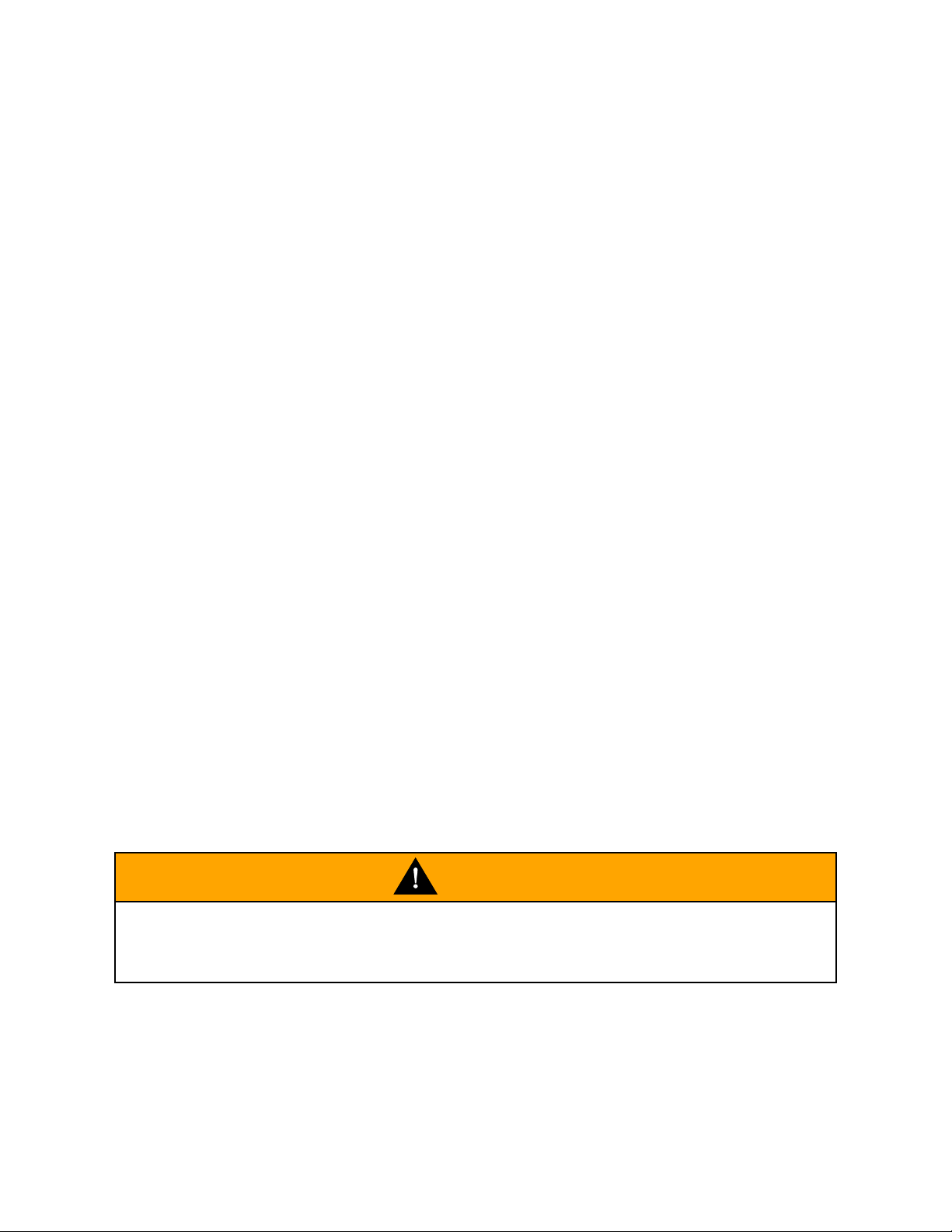
Sealed Bearings
Note
Sealed bearings can be identified by their integrated seals.
Sealed bearings are lubricated for life by the manufacturer.
Any attempt to change the grease in a sealed bearing will damage the
integrated seals. If the seals are damaged, dirt and water will ingress and the
life of the bearing will be greatly reduced.
ceon
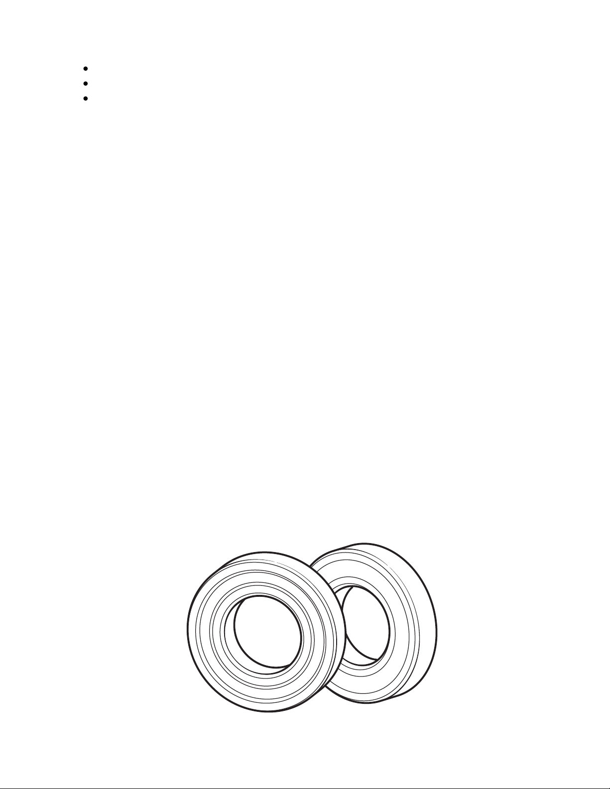
Taper Bearings
Grease must be forced between the inner race and the roller carrier.
1.
Rotate the bearing to ens ure that the grease is distributed over the entire
circum ference of the internal parts.
2.
Any excess grease should be smeared on the outside of the rollers .
3.
Service Manual - Scrambler 1200 XC 16 of 640
Page 17
ceon
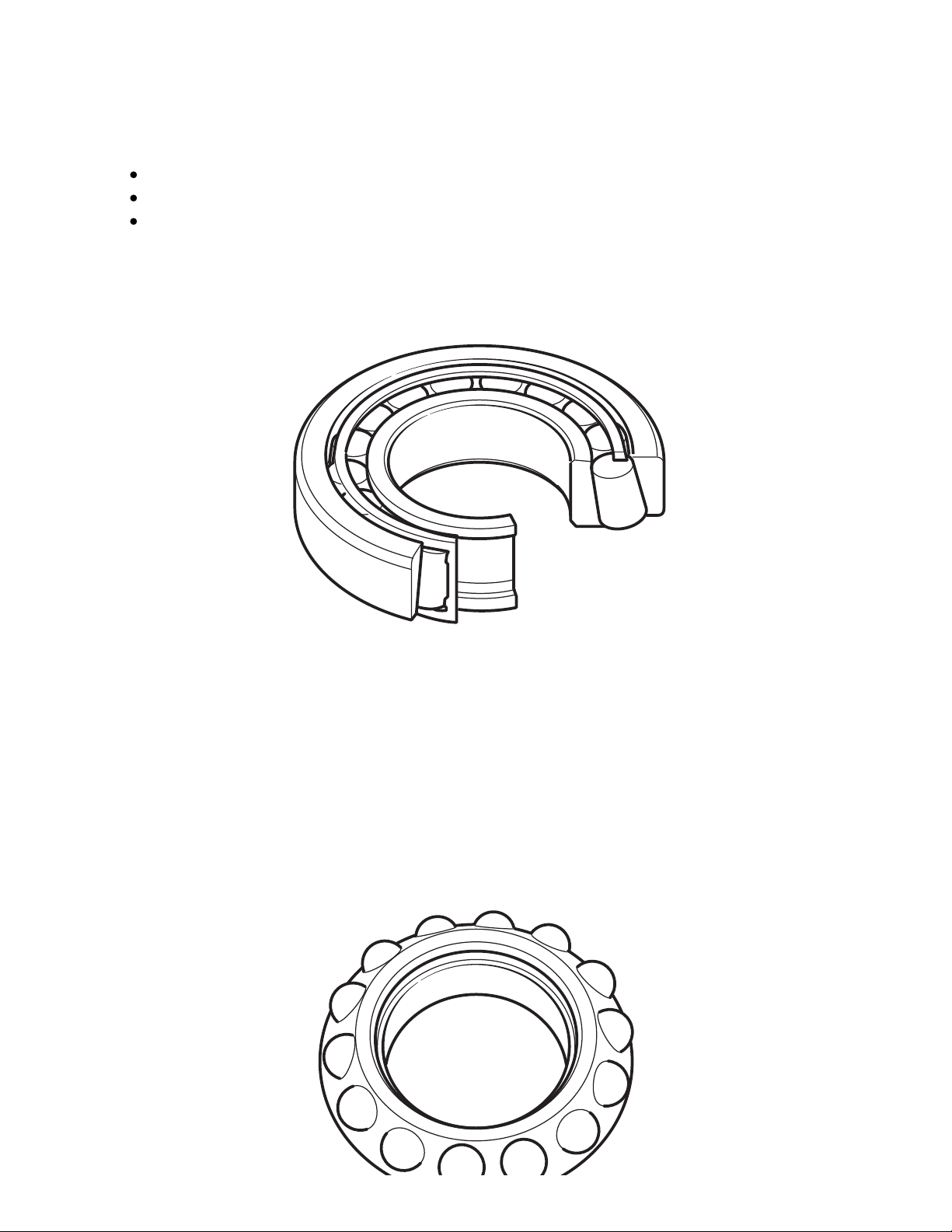
Angular Contact and Ball Bearing
Grease the bearing races and the ball bearing carrier.
1.
Rotate the bearing to ens ure that the grease is distributed over the entire
circum ference of the internal parts.
2.
ceop
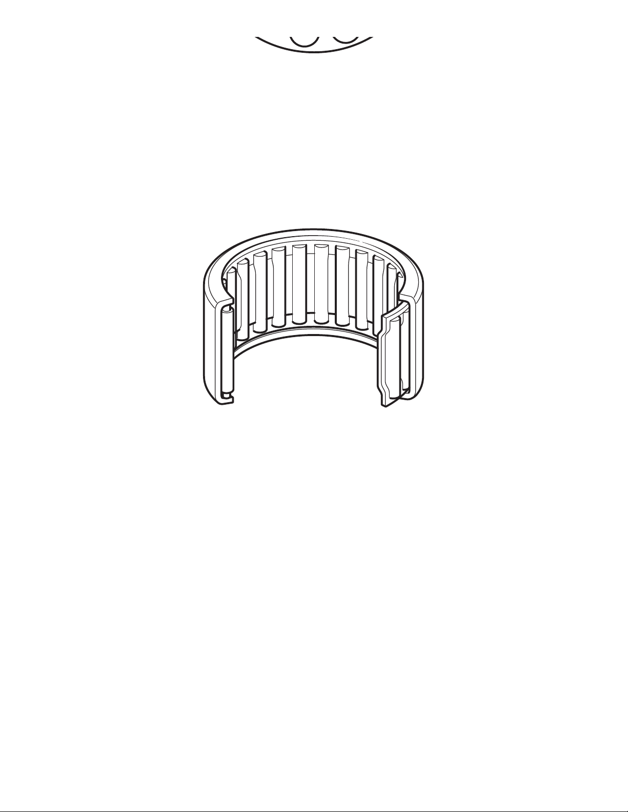
Needle Roller Bearings
Coat the needle rollers with grease.
1.
Ensure the needle rollers turn so that the grease is distributed over the entire
circum ference of the internal parts.
2.
As sem ble the parts, adjus t and check as neces sary.
3.
Metal Bushes
Disass emble the parts as necess ary to access the bus h.
1.
Rem ove the old grease.
2.
Apply fresh grease to the metal bush.
3.
Fuel Handling Precautions
General
The following information provides basic precautions which must be observed if
Service Manual - Scrambler 1200 XC 17 of 640
Page 18
petrol (gas oline) is to be handled safely. It also outlines other areas of risk which
mus t not be ignored. This inform ation is iss ued for basic guidance only and, if in
doubt, appropriate enquiries should be made to your local Fire Officer.
Petrol – Gasoline
When petrol (gasoline) evaporates it produces 150 times its own volum e in vapour
which when diluted with air becom es a readily ignitable mixture. The vapour is
heavier than air and will always fall to the lowes t level. It can readily be distributed
throughout any indoor environment by air currents, consequently, even a small
spillage of petrol (gas oline) is potentially very dangerous.
WARNING
Petrol (gasoline) is highly flam m able and can be explosive under certain
conditions. When opening the fuel tank cap always observe all the following items:
Turn the motorcycle ignition switch OFF.
Do not sm oke.
Always have a fire extinguisher containing FOAM, CO2, HALON or POWDER close
at hand when handling or draining fuel or fuel system s. Fire extinguishers must
als o be present in areas where fuel is stored.
Always disconnect the vehicle battery, negative (black) lead first, before carrying
out, dism antling or draining work on a fuel sys tem .
Whenever petrol (gasoline) is being handled, drained, stored or when fuel
systems are being dis mantled, make sure the area is well ventilated. All potential
forms of ignition must be extinguis hed or removed (this includes any appliance
with a pilot light). Any lead-lamps must be flame-proof and kept clear of any fuel
spillage.
Warning notices mus t be posted at a safe distance from the site of the work to
warn others that petrol (gasoline) is being openly handled. The notice must
ins truct the reader of the precautions which mus t be taken.
Failure to obs erve any of the above warnings may lead to a fire hazard which could
result in pers onal injury.
WARNING
No one should be permitted to repair components associated with petrol
(gas oline) without first having specialis t training on the fire hazards which may be
created by incorrect installation and repair of items associated with petrol
(gas oline).
Repairs carried out by untrained personnel could bring about a safety hazard
leading to a risk of personal injury.
Service Manual - Scrambler 1200 XC 18 of 640
Page 19
WARNING
Draining or extraction of petrol (gasoline) from a vehicle fuel tank mus t be carried
out in a well ventilated area.
The receptacle used to contain the petrol (gas oline) must be more than adequate
for the full amount of fuel to be extracted or drained. The receptacle should be
clearly marked with its contents, and placed in a safe storage area which meets
the requirements of local authority regulations.
When petrol (gasoline) has been extracted or drained from a fuel tank, the
precautions governing naked lights and ignition sources should be maintained.
Failure to obs erve any of the above warnings could bring about a safety hazard
leading to a risk of personal injury.
Fuel Tank Removal
Fuel tanks should have a 'PETROL (GASOLINE) VAPOUR' warning label attached to
them as soon as they are removed from the vehicle. In all cases, they must be stored
in a secured, marked area.
Chassis Repairs
WARNING
If the motorcycle is involved in an accident or collis ion it mus t be taken to an
authoris ed Triumph dealer for repair or inspection. Any accident can caus e
dam age to the motorcycle, which if not correctly repaired, may caus e a second
accident which may res ult in injury or death.
The frame mus t not be modified as any modification to the frame such as welding
or drilling may weaken the frame resulting in an accident.
Electrical Precautions
The following guidelines are intended to ensure the safety of the operator whils t
preventing dam age to the electrical and electronic components fitted to the
motorcycle. Where necessary, specific precautions are detailed in the relevant
sections of this manual which should be referred to prior to commencing repair
operations.
Equipm ent - Prior to commencing any test procedure on the motorcycle ens ure that
the relevant test equipment is working correctly and any harnes s or connectors are in
good condition, in particular mains leads and plugs.
WARNING
Service Manual - Scrambler 1200 XC 19 of 640
Page 20
WARNING
The ignition sys tem produces extrem ely high voltages . Do not touch any part of the
ignition sys tem or any cables while the engine is running.
An electric shock caus ed by contact with the ignition system may lead to illness,
injury or death.
WARNING
Wearers of surgically implanted heart pacemaker devices should not be in close
proximity to ignition circuits and/or diagnos tic equipment.
The ignition sys tem and any diagnostic equipm ent may interrupt the normal
operation of such devices causing illnes s or death.
WARNING
The battery contains harmful materials . Always keep children away from the
battery whether or not it is fitted in the motorcycle.
Do not jump start the battery, touch the battery cables together or reverse the
polarity of the cables as any of these actions may cause a spark which would
ignite battery gas es caus ing a risk of personal injury.
High Voltage Circuits - Whenever disconnecting live H.T. circuits always use insulated
pliers . Exercise caution when meas uring the voltage on the coil terminals while the
engine is running. High voltage spikes can occur on these terminals.
Connectors and Harness - The engine of a motorcycle is a particularly hostile
environm ent for electrical com ponents and connectors. Always ensure thes e items
are dry and oil-free before dis connecting and connecting test equipm ent. Never force
connectors apart either by us ing tools or by pulling on the wiring itself. Always ensure
locking mechanis ms are disengaged before rem oval and note the orientation to
enable correct reconnection. Ensure that any protective covers and substances are
replaced if disturbed.
Having confirmed a component to be faulty, switch off the ignition and disconnect the
battery negative (black) lead first. Rem ove the component and support the
dis connected harness. When replacing the com ponent keep oily hands away from
electrical connection areas and push connectors home until any locking mechanism
becomes fully engaged.
Battery Disconnecting
Before disconnecting the battery, switch off all electrical equipment.
Service Manual - Scrambler 1200 XC 20 of 640
Page 21

WARNING
To prevent the risk of a battery exploding and to prevent damage to electrical
components ALWAYS dis connect the battery negative (black) lead first. When
reconnecting the battery, always connect the pos itive (red) lead first, then the
negative (black) lead. Always disconnect the battery when working on any part of
the electrical system .
Failure to obs erve the above warnings may lead to electrical dam age and a fire
hazard which could cause personal injury.
Always ensure that battery leads are routed correctly and are not close to any
potential chafing points.
Disciplines
Switch off the ignition prior to making any connection or disconnection in the system.
An electrical surge can be caus ed by disconnecting 'live' connections which can
dam age electronic com ponents.
Ensure hands and work surfaces are clean and free of grease, swarf, etc. as grease
collects dirt which can cause tracking or high-resis tance contacts.
Prior to comm encing any test, and periodically during any tes t, touch a good earth to
dis charge body static. This is because some electronic components are vulnerable
to static electricity.
Electrical Wires
All the electrical wires are either single-colour or two-colour and, with only a few
exceptions , must be connected to wires of the sam e colour. On any of the two-colour
wires there is a greater am ount of one colour and a less er amount of a second
colour. A two-colour wire is identified by first the primary colour and then the
secondary colour. For example, a yellow wire with thin red stripes is referred to as a
'yellow/red' wire; it would be a 'red/yellow' wire if the colours were reversed to make
red the main colour.
Electrical Testing
For any electrical system to work, electricity must be able to flow in a complete circuit
from the power source (the battery) via the components and back to the battery. No
circuit means no electrical flow. Once the power has left the positive side of the
battery and run through the component it must then return to the battery on its
negative side (this is called earth or ground). To save on wiring, connections and
space, the negative side of the battery is connected directly to the frame or engine.
Around the frame and engine will be various other ground points to which the wiring
coming from com ponents will be connected. In the cas e of the starter motor it bolts
directly to the engine, which is bolted to the frame. Therefore the frame and engine
Service Manual - Scrambler 1200 XC 21 of 640
Page 22

als o form part of the earth return path.
Ohm’s Law
The relationship between voltage, current and resistance is defined by Ohm’s Law.
The potential of a battery is measured in volts (V).
The flow of current in a circuit (I) is measured in amperes.
The power rating of a consumer is measured in watts (W).
The resistance (R) of a circuit is meas ured in Ohms.
Ohm’s law, for practical work can be described as -
Power is calculated by multiplying Volts x Amps -
By trans pos ing either of thes e formulae, the value of any unit can be calculated if the
other two values are known.
For example, if a battery of 12 V is connected to a bulb of 60 W:
the current flowing in the circuit can be calculated by using -
the bulb res istance can be calculated by using -
Service Manual - Scrambler 1200 XC 22 of 640
Page 23
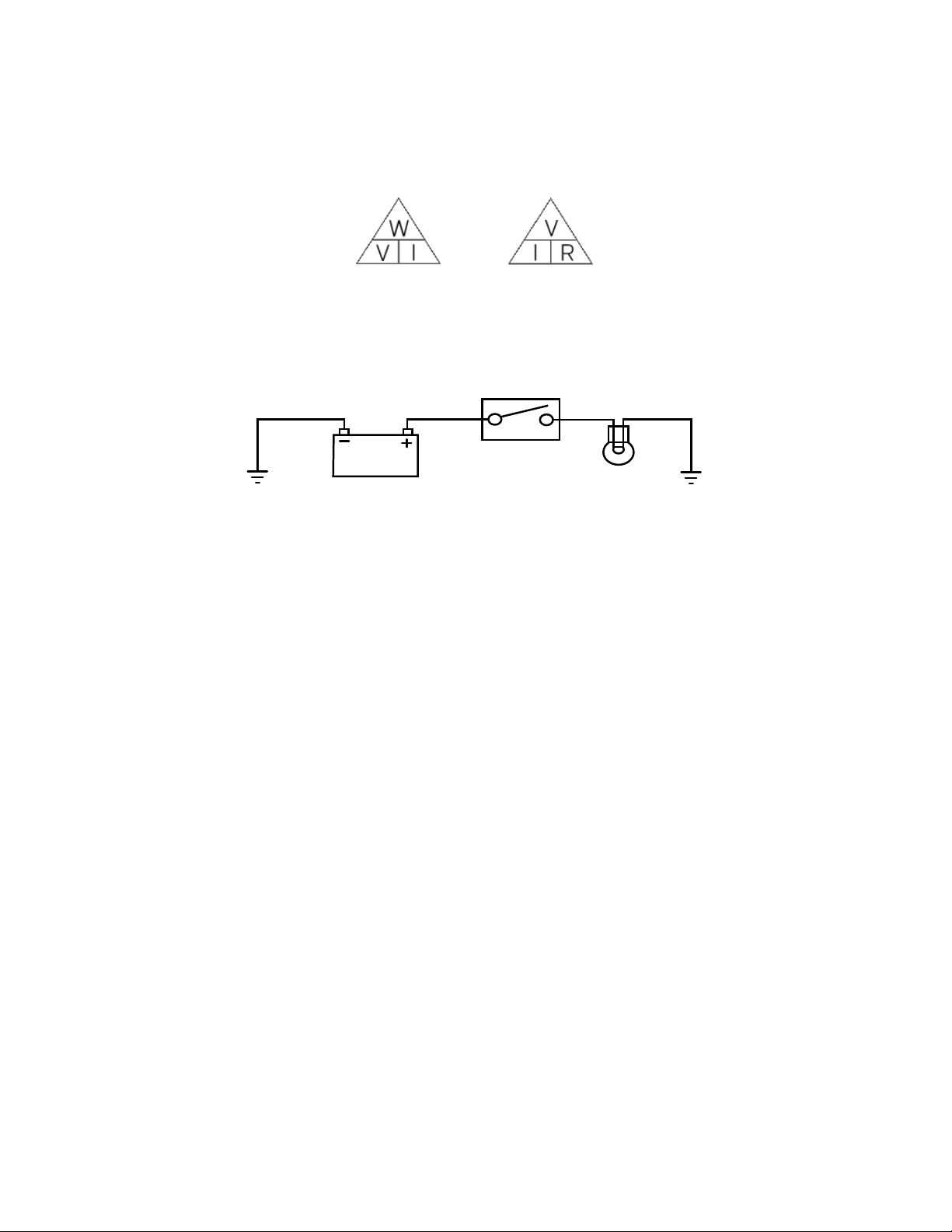
To us e either of the following triangles, put your finger over the value you want to find.
Multiply the remaining values if side by side, or divide if one is over the other.
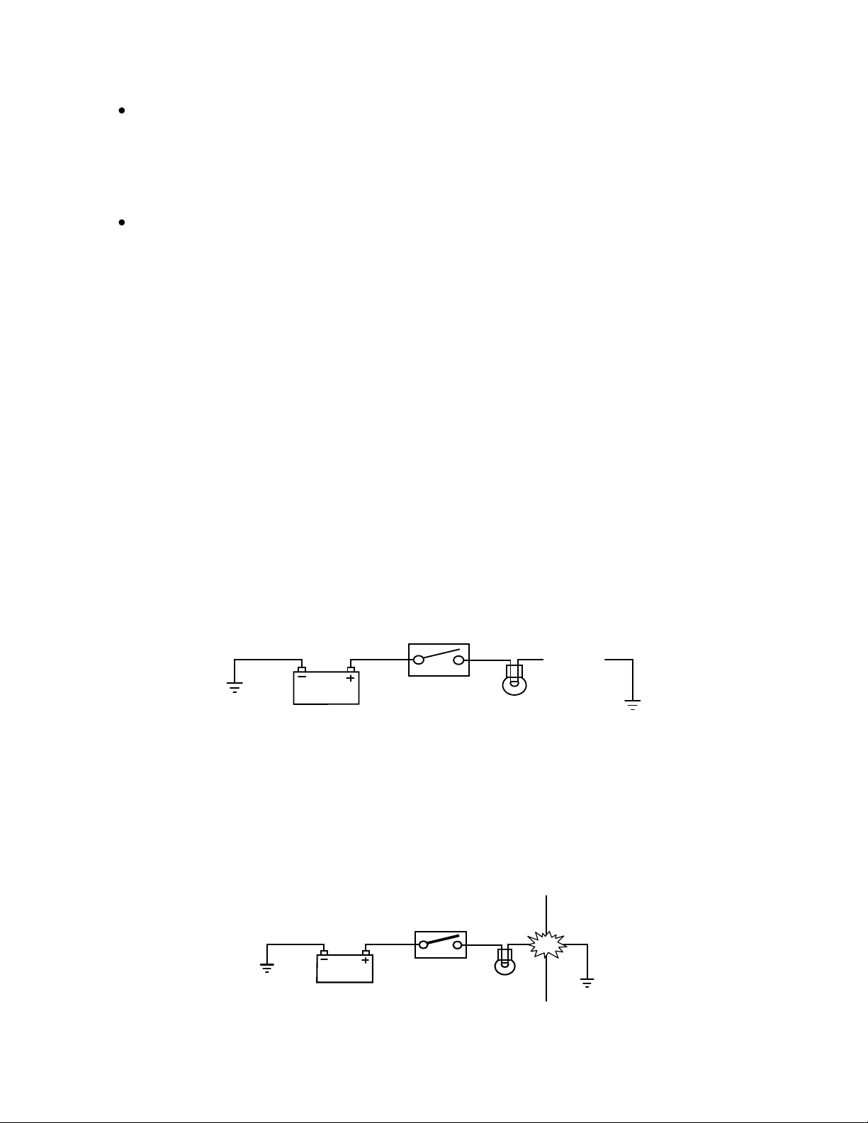
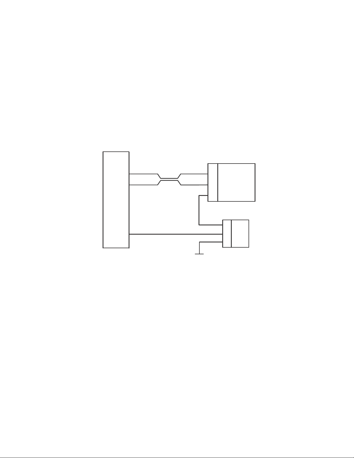
Basic Electrical Circuits
Basic Circuit Diagram
In the above circuit an electrical reservoir (the battery) is connected via a cable to a
terminal on the controlling device (the switch) whos e contacts are either open or
clos ed. The other terminal on the switch is connected via a cable to the consumer
(the bulb), and the other side of the bulb filament is connected to ground (earth) by
another cable. The ground point is us ually a part of the frame or engine, to which the
battery negative terminal is also connected.
When the switch contacts are open (as shown in the diagram), the circuit is broken
and no current flows. When the switch contacts are closed, the circuit is made and
current flows from the battery positive terminal through the switch contacts and bulb
filam ent to ground. The frame completes the circuit to the battery negative terminal
and the bulb illuminates .
Although som e circuits on the circuit diagram may at firs t seem more com plicated, it
will generally be found that they can be broken down into sections which do not differ
greatly from the basic circuit above.
Circuit Diagrams
Circuit diagram s are created to provide a 'picture' of the electrical system and to
identify the route taken by each individual wire through the system , in order to identify
which com ponents it feeds and which connectors the wire runs through. Circuit
diagrams are an essential tool for fault finding, as it is possible to locate start and
finis h points for a circuit without having to manually trace the wire through the
motorcycle itself. Circuits diagrams may look confus ing at first but when they are
studied closely they soon become logical.
Service Manual - Scrambler 1200 XC 23 of 640
Page 24
Due to the com plex circuits and the num ber of individual wires, Trium ph uses two
types of circuit diagram in its Service Manuals.
Within the manual, conventional circuit diagrams are used to show the layout of
the main circuits of the motorcycle. Thes e are: Engine managem ent/ignition,
Lighting, Starting and Charging and Auxiliary and Access ory. In thes e diagram s
no attempt is made to show the components of the system in any particular order
or pos ition in relation to the motorcycle.
At the back of the Service Manual a full colour layout circuit diagram is used to
show the main electrical com ponents in a pos ition similar to the actual position
on the motorcycle.
Both of these circuit diagrams us e sim ilar symbols to illus trate the various sys tem
components and will be accompanied by a key indicating circuit diagram
components and wiring colour codes.
Circuit diagram s als o depict the inner workings of a switch hous ing (i.e. which wire
connects to which when a switch is turned from one pos ition to another) so that a test
of that switch can be made us ing the wire term inals in the connector instead of
dis ass embling the switch itself.
Tracing Circuits
The following is a description of two types of common electrical failures , and som e of
the methods which may be used to find them .
Open Circuit
A break in an electrical circuit - current cannot flow. Us ually caused by a break in a
wire or cable or by a loose connection. Open circuits can often be intermittent, making
diagnosis difficult.
Short Circuit
A 'short cut' in an electrical circuit - current bypasses the intended circuit, either to
Service Manual - Scrambler 1200 XC 24 of 640
Page 25
ground or to another, different circuit. Often caused by failure of the cable ins ulation
due to chafing or trapping of the wire. There are two different types of short circuit -
short to ground and short to battery Voltage.
A short to ground means that the current is going to ground before it reaches the
component it is supposed to feed. These are often caus ed by chafing of the harness
to the fram e or wires trapped between a bolted com ponent, and will often blow the
fuse on that circuit.
A short to battery voltage (12 Volts) is caused by a live power supply wire contacting
an adjacent cable. Note that it is also possible for a 5 Volt sensor reference voltage to
short to an adjacent circuit, which can also cause electrical failures and DTCs
(Diagnostic Trouble Code) to be stored.
When tracing a wire that is suspect, carefully check the circuit diagram before
starting. Remember:
a wire may diverge at a splice and go off to feed other circuits. If these circuits are
working, check for wiring faults from the splice onwards .
the circuit diagram is not an accurate guide to the actual location of the parts
when fitted on the motorcycle. It is a schematic diagram of the circuits.
particularly where engine management items are concerned, the circuit is only
completed by the ECM. If the ECM is not connected, the circuit may register as
open.
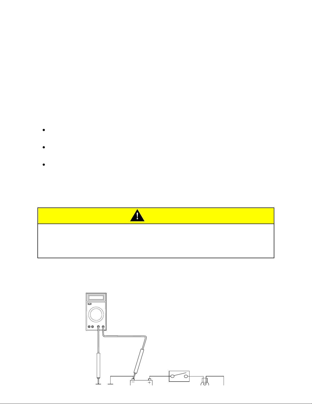
To Check Continuity:
CAUTION
Ensure the circuit being tested is switched off before measuring continuity.
Dam age to the Digital Multi Meter (DMM) may res ult from testing a 'live' circuit with
the meter set to resistance (Ω).
In the example below, the ground circuit continuity is being tested from the battery to
the frame.
Ω
0.0
Service Manual - Scrambler 1200 XC 25 of 640
Page 26
Locate each end of the wire.
Set the Digital Multi Meter (DMM) to res istance check Ohms.
Probe each end of the wire.
If there is continuity, the meter will usually bleep or regis ter the resis tance of the
cable.
A high resistance figure could indicate a dirty or corroded connection.
If there is a break in the wire, the meter will not bleep or regis ter a resis tance.
By probing the wire in various places, the position of a high resistance or break in
the wire (open circuit) can be narrowed down until it is found.
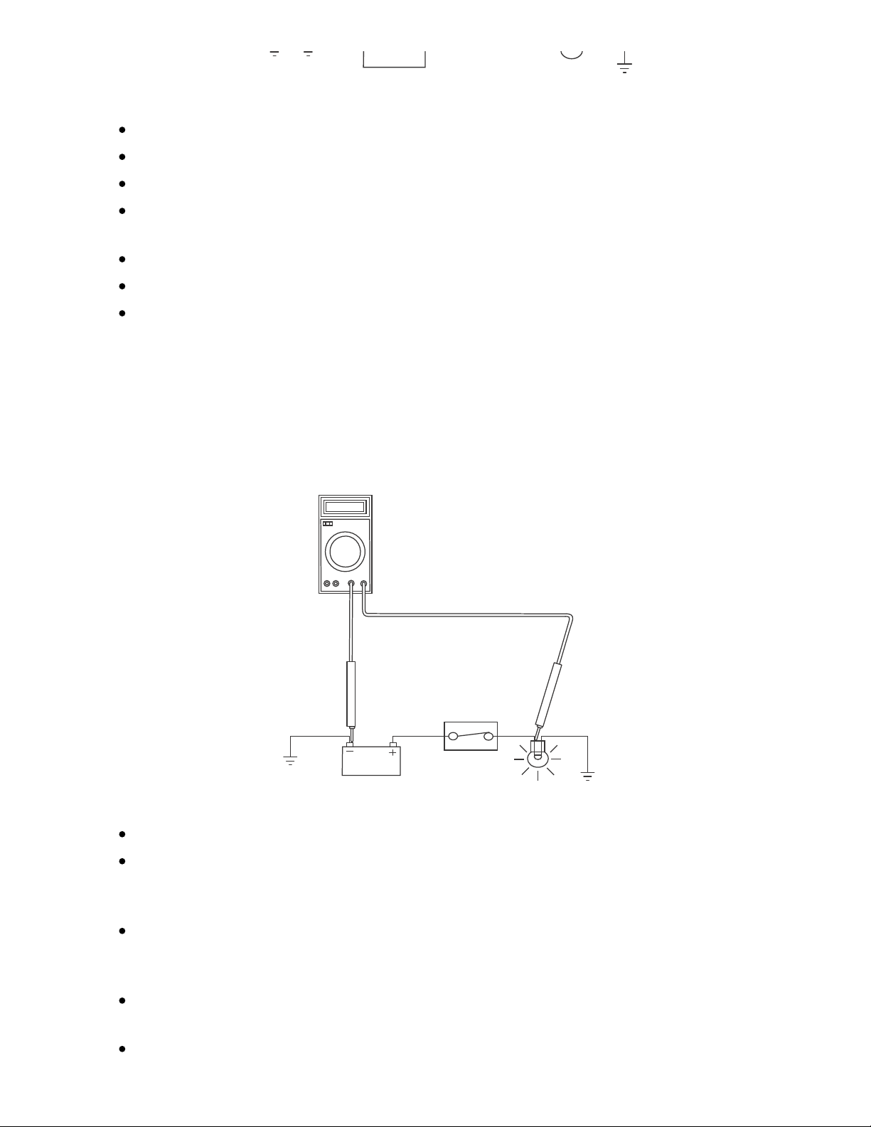
To Measure Voltage:
In the example below, the circuit voltage is being meas ured at the bulb positive (+)
terminal.
V
12.7
Turn the circuit to be tested 'ON'.
Set the Digital Multi Meter (DMM) to Voltage Check (V). Ensure the multi meter is
set to DC Volts for direct current circuits (mos t circuits) or AC Volts for alternating
current circuits (typically alternator output voltage tests).
Set the range of the DMM to the range best suited to the voltage of the circuit
being tested (typically 20 Volts for most DMMs). Refer to the DMM manufacturers
ins tructions.
Connect the black (ground) lead of the DMM to a reliable ground connection
(usually the battery or frame ground).
Locate the pos itive terminal of the wire or component to be tested.
Service Manual - Scrambler 1200 XC 26 of 640
Page 27
Connect the red (positive) lead of the DMM to the positive terminal.
Read the voltage from meter.
Splices
Splices are probably the most com m on cause of wiring faults after connectors .
Splices are made where two or more wires com e together and diverge in different
directions, usually to feed a different circuit.
To locate a splice, it is necessary to peel back the insulation and examine the splice
for its integrity. The mos t comm on fault is where one of the wires at the joint has
come adrift usually causing the circuit it feeds or grounds to becom e 'dead'.
Switches
To check a switch, set the multimeter to resistance/continuity and probe the two pins
that form a closed circuit when the switch is pus hed. If the switch is working correctly,
the resistance should register or the meter will bleep.
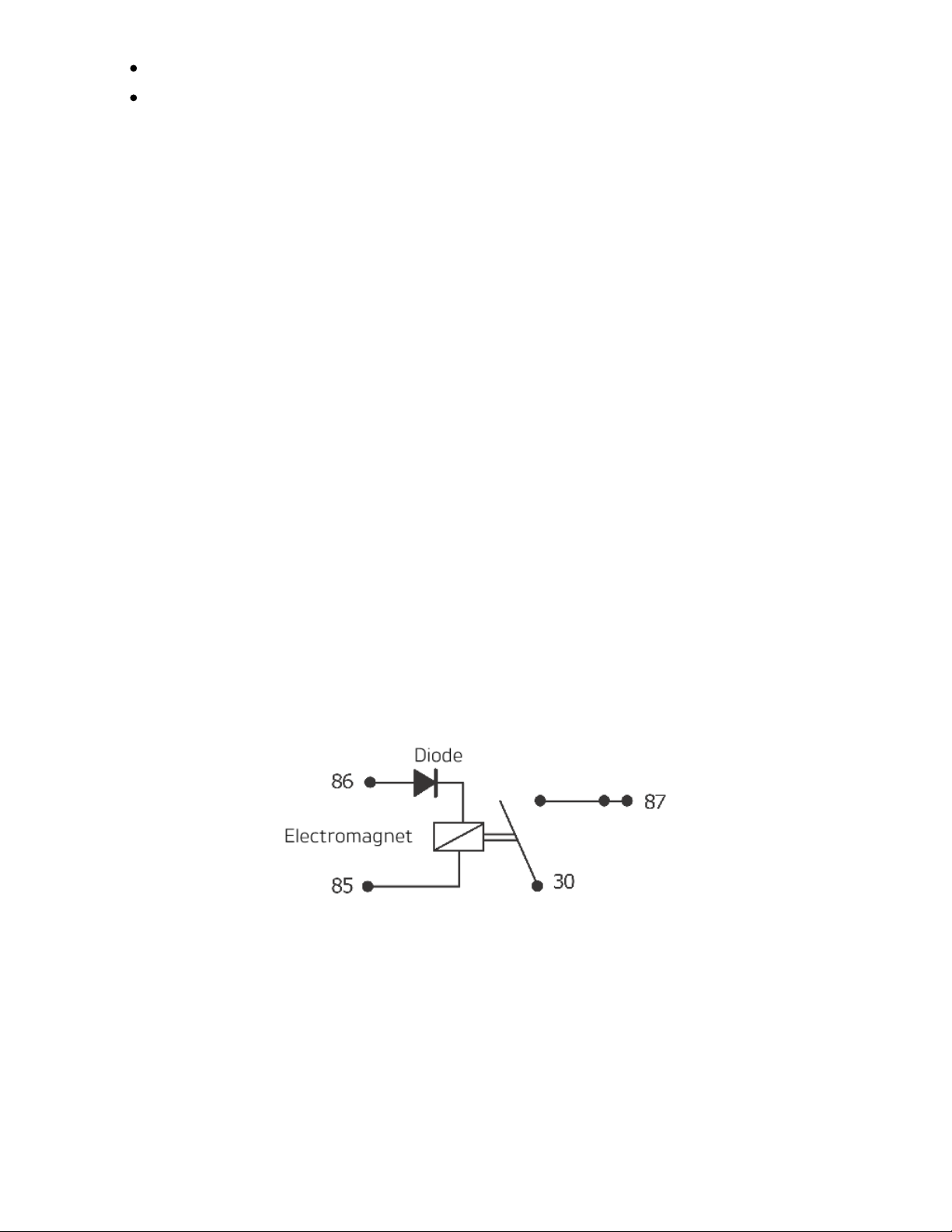
Relays
All relay cases have a circuit path engraved on them showing the circuit path across
the electromagnet and the switch. Before making any checks , first note the pin
des ignations, current paths, and whether or not there is a diode in either circuit path.
Make continuity checks across the electromagnet first, us ually from pin 86 (positive)
to pin 85 (negative). If a diode appears in the circuit use the diode check on the
multimeter (Volts scale) in the direction of current flow. If there is no diode, use the
resistance check facility. An open circuit or unus ually high resistance value indicates
a faulty relay.
To check the switch side, apply a 12 Volt supply between pins 86 and 85. With the
Service Manual - Scrambler 1200 XC 27 of 640
Page 28
supply connected, the relay should be heard to click and there should be continuity
between pins 30 and 87. An open circuit indicates a faulty relay.
CAN (Controller Are a Networking)
CAN (som etimes called CANbus ) is a protocol for data communication between
Electronic Control Modules (ECMs). Each ECM on the network is connected by a
single pair of twisted wires (or bus) which are used for the transm iss ion of vehicle
sensor data. By us ing CAN, the overall num ber of sys tem sens ors, and the am ount of
cabling required to allow ECMs to communicate with each other is greatly reduced.
This saves cost, weight and space, and makes the sys tem more reliable, as the
physical number of wires and connections is reduced.
4
5
16
R
U
B28
B27
A34
B
KY
1
3
2
CAN works by each ECM sending out 'packets' of information (such as engine speed
or fuel consum ption inform ation) on to the network bus (note that the network must
be free of data before any ECM is allowed to transm it). This data is given a priority
according to its im portance (for example 'engine speed' may have a higher priority
than 'low fuel level'), so that even if two ECMs send data at the sam e time, high
priority information is always sent first. Lower priority data is then res ent after the high
priority data has been received by all ECMs on the network.
The receiving ECM confirms the data has been received correctly and that the data is
valid, and this information is then used by the ECM as necessary. Specific data not
required by an ECM will still be received and acknowledged as correct but then
dis regarded (for example if an ECM does not require 'clutch switch pos ition'
inform ation, this data packet would be ignored).
This allows for a very high speed system of comm unication, which is also very
reliable. Should one ECM fail or trans mit corrupted or otherwis e incorrect messages,
none of the other ECMs on the network will be affected, and after a certain time that
ECM will be prevented from trans mitting further messages until the fault is rectified.
This stops the ECM from clogging the network with incorrect data and preventing
Service Manual - Scrambler 1200 XC 28 of 640
Page 29
other messages from getting through. The fault would then be reported by a DTC
(Diagnostic Trouble Code).
Triumph currently us es CAN for comm unication between the following ECMs :
Engine ECM
Instruments
ABS ECM
Immobiliser or Chassis ECM
Diagnostic connector
Inertial Measurement Unit (if fitted)
Audio sys tem (if fitted)
Electronic steering lock (if fitted)
LED Headlights (if fitted).
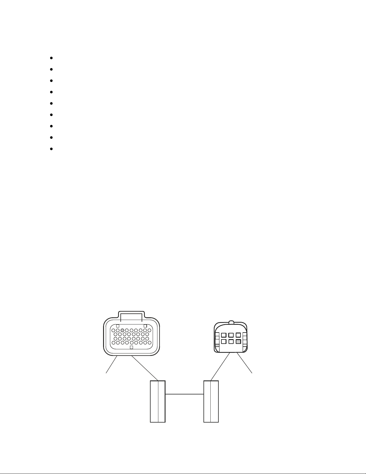
LIN (Local Interconnect Network)
LIN (Local Interconnect Network) is a serial network protocol used for communication
between components in vehicles. The bus is a single master/multiple slave bus that
uses a single wire to transmit data.
By us ing LIN, the am ount of cabling required to allow components to communicate
with each other is greatly reduced. This saves cost, weight and space, and makes
the system more reliable, as the physical num ber of wires and connections is
reduced.
The ins truments us e som e of this data internally and also broadcasts it on the
CANbus (Controller Area Networking) for use on the motorcycle as necess ary.
Information (such as headlight main beam) is being requested continuously by the
Instruments, once a confirm ation of the reques t is recognised the instruments will
react accordingly.
7 4
25
34
17
9 1
10
18
26
1
1
3
4
6
2
Service Manual - Scrambler 1200 XC 29 of 640
Page 30

Instruments
1.
Switch housing (left hand side)
2.
Example
Press ing the headlight main beam button on the switch housing (left hand
handlebar) confirms to the instruments that headlight main beam is required.
The ins truments confirm the data has been received correctly and that the data is
valid.
Once confirm ed the headlight main beam is switched on.
Triumph currently us es LIN on certain models for communication between the
ins truments and the following components:
Fog light button
Heated seat
Dip beam/Daytime running lights (DRL) switch (if equipped)
Mode button
Turn signal switch
Joystick button
Horn button
High beam button
Service Tools
Serv ice Tools
Special service tools have been developed to facilitate rem oval, dis mantling and
ass embly of certain mechanical com ponents in a practical manner without causing
dam age. Some operations in this Service Manual cannot be carried out without the
aid of the relevant service tools . Where this is the case, the tools required will be
des cribed during the procedure.
Special Service Tools:
Service Manual - Scrambler 1200 XC 30 of 640
Page 31

cdgh
T3880001 - Fuel Pressure Gauge
T3880016 - Balancer Gear C-Spanner
T3880039
T3880023 - 50 mm Socket
T3880039 - Idler Gear Timing Pin
T3880041
cczb
T3880041 - Idler Gear Timing Wrench
T3880053 - Wheel Bearing Extraction Kit
Service Manual - Scrambler 1200 XC 31 of 640
Page 32

T3880057 - Triumph Diagnos tic Interface
T3880067 - Fork Spring Compressor
cczb
ccg s
T3880075 - Bearing Installer
T3880085 - Fork Piston Holder
cdoa
T3880104 - Swinging Arm Adjuster
Wrench
T3880105 - Torque Angle Gauge
Service Manual - Scrambler 1200 XC 32 of 640
Page 33

Specifications
Engine
Engine Configuration
Liquid cooled parallel twin,
270° firing angle
Arrangement
Transverse in-line
Displacem ent
1200 cc
Bore x Stroke
97.6 x 80 mm
Com pression Ratio
11.00:1
Cylinder num bering
Left to right
Firing Order
1-2
Cylinder Head and Valve s
Cylinder head
Flatnes s
tolerance
0.030 mm
Valve Head Diameter
Inlet
35.60 mm
Exhaust
29.70 mm
Valve Lift
Inlet
10.3 mm
Exhaust
9.2 mm
Valve Stem Diameter
Inlet
4.975 - 4.990 mm (standard)
4.965 mm (service limit)
Exhaust
4.970 - 4.980 mm (standard)
Service Manual - Scrambler 1200 XC 33 of 640
Page 34

4.960 mm (service limit)
Valve Guide Bore Diameter
Inlet
5.000 - 5.015 mm (standard)
5.043 mm (service limit)
Exhaust
5.000 - 5.015 mm (standard)
5.043 mm (service limit)
Valve Stem to Guide
Clearance
Inlet
0.010 - 0.040 mm (standard)
0.078 mm (service limit)
Exhaust
0.020 - 0.045 mm (standard)
0.083 mm (service limit)
Valve Seat Width (in head)
Inlet
1.000 - 1.100 mm (standard)
1.500 mm (service limit)
Exhaust
1.200 - 1.300 mm (standard)
1.700 mm (service limit)
Valve Seat Width (valve)
1.50 - 1.85 mm
Valve Seat Angle
90° inclusive
Valve Spring Length
49.9 mm
Inlet/Exhaust Valve Spring 'Load at Length'
214 N +/- 10 at 39.5 mm
Valve Clearance
Inlet
0.05 - 0.13 mm
Exhaust
0.12 - 0.22 mm
Service Manual - Scrambler 1200 XC 34 of 640
Page 35

Camshafts
Cam shaft Tim ing (at 1 mm lift)
Inlet
Open 5.0° ATDC
Close 41.0° ABDC
Duration 216°
Exhaust
Open 39.0° BBDC
Close 4.0° BTDC
Duration 215°
Cam shaft Journal Diameter
22.930 - 22.960 mm
Cam shaft Journal Clearance
0.040 - 0.091 mm (standard)
0.130 mm (service limit)
Cam shaft Journal Bore Diam eter
23.000 - 23.021 mm
Cam shaft End Float
0.05 - 0.20 mm (standard)
Cam shaft Run-out
0.015 mm (standard)
Clutch and Primary Drive
Primary Drive Type
Gear
Reduction Ratio
1.26:1 (93/74)
Clutch Type
Wet multi-plate
No. of Friction Plates
8
Steel Plate Flatnes s Limit
0.15 mm
Service Manual - Scrambler 1200 XC 35 of 640
Page 36

Friction Plate Flatnes s Limit
0.20 mm
Friction Plate Thickness (new)
2.90 - 3.10 mm
Friction Plate Thickness (service limit)
2.80 mm
Clutch Pack Height
38.00 mm + 0.34/-0.66 mm
Clutch Actuation Method
Cable
Cable Free Play (at lever)
2.0 - 3.0 mm
Piston
Cylinder Barrel Diam eter - 10 mm from the
top of the barrel
97.585 - 97.601 mm (standard)
Cylinder Barrel Diam eter - 97 mm from the
top of the barrel
97.600 - 97.615 mm (standard)
Piston Diam eter
97.570 - 97.580 mm (standard)
97.530 mm (service lim it)
Piston Ring to Groove
Clearance
Top
0.02 - 0.07 mm (standard)
0.085 mm (service limit)
Second
0.02 - 0.06 mm (standard)
0.075 mm (service limit)
Piston Ring Groove Width
Top
1.21 - 1.24 mm (standard)
Second
1.01 - 1.03 mm (standard)
Oil
2.51 - 2.53 mm (standard and
Service Manual - Scrambler 1200 XC 36 of 640
Page 37

service lim it)
Piston Ring End Gap
Top
0.183 - 0.383 mm (standard)
0.503 mm (service limit)
Second
0.353 - 0.553 mm (standard)
0.673 mm (service limit)
Oil
0.153 - 0.703 mm (standard)
0.843 mm (service limit)
Gudgeon Pin Bore Diameter In Pis ton
21.004 - 21.012 mm (standard)
21.040 mm (service lim it)
Gudgeon Pin Diameter
20.995 - 21.000 mm (standard)
20.985 mm (service lim it)
Connecting Rod Small End Diam eter
21.016 - 21.029 mm (standard)
21.039 mm (service lim it)
Connecting Rod Big End Diameter
41.000 - 41.009 mm (standard)
Connecting Rod Big End Side Clearance
0.15 - 0.30 mm (standard)
0.50 mm (service lim it)
Crankshaft
Crankshaft Big End Journal Diameter
38.000 - 37.984 mm (standard)
37.9469 mm (service limit)
Service Manual - Scrambler 1200 XC 37 of 640
Page 38

Crankshaft Big End Bearing Clearance
0.036 - 0.061 mm (standard)
0.100 mm (service limit)
Crankshaft Main Journal Diameter
43.108 - 43.092 mm (standard)
43.052 mm (service lim it)
Crankshaft Main Bearing Clearance
0.018 - 0.042 mm (standard)
0.100 mm (service limit)
Crankshaft End Float
0.05 - 0.20 mm (standard)
0.50 mm (service lim it)
Crankshaft Run-out
0.02 mm (standard)
0.035 mm (service limit)
Transmission
Type
6 Speed, Constant Mes h
Gear Ratios Primary
1.26:1 (93/74)
1st
3.50:1 (49/14)
2nd
2.50:1 (45/18)
3rd
1.85:1 (37/20)
4th
1.48:1 (37/25)
5th
1.30:1 (35/27)
6th
1.17:1 (34/29)
Service Manual - Scrambler 1200 XC 38 of 640
Page 39

Gear Selector Fork
Thickness
5.90 - 6.00 mm (standard)
5.80 mm (service lim it)
Gear Selector Groove Width
6.10 - 6.20 mm (standard)
6.30 mm (service lim it)
Gear Selector Fork to Groove
Clearance
0.1 - 0.3 mm (standard)
0.50 mm (service lim it)
Final Drive
Final Drive Type
Chain - EK525ZVX3, 110 links
Final Drive Ratio
2.75:1 (44/16)
Drive Chain Slack
See
Final Drive Chain Adjus tment
Drive Chain Lubrication
Chain spray s uitable for X-ring chains
Lubrication
Oil Capacity (including
filter, dry fill)
3.80 litres
Oil and Filter Change
3.40 litres
Oil Change only
3.20 litres
Recommended Oil
Approval Rating
API SH (or higher) and JASO MA
Viscos ity
10W/40 or 10W/50
Type
Semi or fully synthetic
Service Manual - Scrambler 1200 XC 39 of 640
Page 40

Oil Press ure (in main
gallery)
3.00 - 3.60 bar at 3,500 rpm
Oil Pump Rotor Tip
Clearance
0.15 mm (standard)
0.20 mm (service lim it)
Oil Pump Body Clearance
0.15 - 0.239 mm (standard)
0.369 mm (service limits)
Oil Pump Rotor End Float
0.04 - 0.09 mm (standard)
0.12 mm (service lim it)
Ignition System
Type
Digital electronic
Electronic Rev-Limiter
7,500 rpm
Pick up Coil Air Gap
Fixed, not adjustable
Primary Coil Resis tance
0.185 Kohm s
Ignition Coil Type
Inductive, plug top
Spark Plug Type
NGK LMAR8A-9
Spark Plug Gap
0.9 mm +0.0/-0.1 mm
Fuel System
Fuel Type
Unleaded, 91 RON (CLC or AKI octane rating
(R+M)/2 of 87 or higher)
Fuel Tank Capacity
16 litres
Service Manual - Scrambler 1200 XC 40 of 640
Page 41

Low Level Warning Light
3.25 litres
Fuel Pum p Type
Subm erged, electric
Fuel Pres sure (nominal)
3.5 bar
Purge Control Sys tem
Modulated, vacuum
Emissions Control Syste m
Type
Digital electronic
Idle Speed
1,000 rpm
Injector Type
Multi hole, solenoid operated plate valve
Throttle
Electronically controlled throttle bodies
Idle Speed Control
Electronic
Control Sensors
Atmospheric air pressure, throttle position, twist
grip pos ition, coolant temperature, crankshaft
pos ition, oxygen sensor, intake air temperature,
gear pos ition, MAP, vehicle speed (from ABS)
Catalysts
One, in the catalytic converter box
Oxygen Sens or
One per cylinder, heated, in header pipe
Evaporative Control
Activated carbon canister (certain markets only)
Cooling System
Coolant Mixture
Premixed
Antifreeze Type
Triumph HD4X Hybrid OAT coolant
Service Manual - Scrambler 1200 XC 41 of 640
Page 42

Cooling System Capacity
1.89 litres
Radiator Cap Opening
Press ure
1.2 bar
Thermostat Opening
Tem perature
88°C
Cooling Fan Switch On
Tem perature
103°C
Tem perature Gauge Sens or
Res istance
173 Ohms (+/- 10%) at 100°C
Suspension
Front Fork Travel
200 mm
Recommended Fork Oil
Grade
Showa SS47
Oil Level (spring, spring seat
and spacer removed and
fork fully compressed)
114 mm
Oil Volum e (dry fill)
602cc
Front Fork Pull Through
45.7 mm +/- 0.5 mm from lower edge of top yoke
to the top of the inner tube (not the top cap)
Fork Spring Rate
4.5 N/mm
Rear Wheel Travel
200 mm
Brakes
Front Type
Four pis ton monobloc calipers acting on twin discs
Service Manual - Scrambler 1200 XC 42 of 640
Page 43

Front Caliper Piston
Diameter
28m m
Front Disc Diameter
320mm
Front Disc Thickness
4.5mm
4.0mm
Front Disc Run-out Max.
0.25m m
Front Mas ter Cylinder
Diameter
18 mm
Recommended Fluid
DOT 4
Rear Type
Twin piston sliding caliper acting on single disc
Rear Caliper Piston
Diameter
28m m
Rear Dis c Diam eter
255mm
Rear Dis c Thickness
5.5mm
5mm
Rear Dis c Run-out Max.
0.25m m
Rear Master Cylinder
Diameter
14m m
Recommended Fluid
DOT 4
Frame
Frame Type
Tubular steel
Service Manual - Scrambler 1200 XC 43 of 640
Page 44

Rake
25.8°
Trail
121.0mm
Maximum . Payload (rider,
pas senger, luggage and
acces sories)
210 kg
Whee ls and Tyres
Front Wheel Size
MT 21 x 2.15
Front Tyre Size
90/90-21 54H
Front Tyre Pressure
2.5 bar (36 lb/ in²)
Front Wheel Rim Axial run-
out
1 mm
Front Wheel Rim Radial
Run-out
1 mm
Rear Wheel Size
MT 17 x 4.5
Rear Tyre Size
150/70R17 69V
Rear Tyre Pressure
2.9 bar (42 psi lb/ in²)
Rear Wheel Rim Axial run-
out
1 mm
Rear Wheel Rim Radial
Run-out
1 mm
Approved Tyres
A list of approved tyres specific to these models is
available from your authorised Triumph dealer, or
on the Internet at www.trium ph.co.uk.
Electrical Equipment
Service Manual - Scrambler 1200 XC 44 of 640
Page 45

Battery Type
YTZ10S
Battery Rating
12 V - 8.6 Amp. Hour
Alternator Rating
18 Amps at 1000 rpm
33 Amps at 6000 rpm
Headlight
LED
Rear Light/Brake Light
LED
Licence Plate Light
LED
Directional Indicator Lights
LED
Torque Wrench Settings
Cylinder Head
Application
Torque
(Nm)
Notes
Cam shaft cover to cylinder head
*
See
Cam shaft Cover -
Installation
Cam shaft drive chain tens ioner blade to
cylinder head
10 Nm
Fit new fixing(s) if
loosened or removed
Cam shaft drive chain tens ioner to cylinder
barrel
16 Nm
Cam shaft fram e to cylinder head
*
See
Cam shaft -
Installation
Cam shaft idler shaft bolt
10 Nm
Fit new fixing(s) if
loosened or removed
Cam shaft s procket to cams haft
*
See
Cam shaft -
Service Manual - Scrambler 1200 XC 45 of 640
Page 46

Application
Torque
(Nm)
Notes
Installation
Fit new fixing(s) if
loosened or removed
Cylinder head dry seal plug
6 Nm
Fit new fixing(s) if
loosened or removed
Cylinder head to crankcas e
*
See
Cylinder Head -
Installation
Exhaust stud to cylinder head
10 Nm
Fit new fixing(s) if
loosened or removed
Flanged plug to cylinder head
22 Nm
Fit new fixing(s) if
loosened or removed
Spark plugs
12 Nm
Service tool
T3880609 - Timing Torque
Lim iter
0.6 Nm
Clutch
Application
Torque
(Nm)
Notes
Clutch cable lower lock nut
3 Nm
Clutch centre nut
98 Nm
Fit new fixing(s) if
loosened or removed
Fit new Belleville
was her
Clutch lever clamp bolts
12 Nm
Clutch lever nut
3.4 Nm
Clutch pres s ure plate to centre
10 Nm
Service Manual - Scrambler 1200 XC 46 of 640
Page 47

Application
Torque
(Nm)
Notes
Clutch switch cover
1 Nm
Balancer, Crankshaft and Crankcase
Application
Torque
(Nm)
Notes
Breather plate to crankcase
9 Nm
Fit new fixing(s) if
loosened or removed
Connecting rod big end bolts
*
See
Connecting Rod -
Installation
Crankcas e breather pipes to crankcase
9 Nm
Fit new fixing(s) if
loosened or removed
Crankcas e to crankcase bolts
*
See
Crankcas e -
As sem bly
Dead shaft clam p pinch bolt
10 Nm
Dead shaft clam p retaining bolt
10 Nm
Fit new fixing(s) if
loosened or removed
Dead shaft preload
*
See
Balancer Shafts
Dynamic Adjustment
Dry s eal plug
23 Nm
Fit new fixing(s) if
loosened or removed
Flanged plug
10 Nm
Fit new fixing(s) if
loosened or removed
Oil filler cap
3 Nm
Plug, front balancer shaft adjuster clam p
23 Nm
Service Manual - Scrambler 1200 XC 47 of 640
Page 48

Application
Torque
(Nm)
Notes
Rear dead shaft retaining washer
12 Nm
Fit new fixing(s) if
loosened or removed
Sprag clutch housing fixings
*
Fit new fixing(s) if
loosened or removed
See
Starter Drive/Sprag
Clutch - Installation
Sprag thrust washer fixings
12 Nm
Fit new fixing(s) if
loosened or removed
Engine Covers
Application
Torque
(Nm)
Notes
Alternator cover embellisher to cover
4 Nm
Fit new fixing(s) if
loosened or removed
Alternator cover to crankcase
10 Nm
Baffle to sump
6 Nm
Cable cover to alternator cover
6 Nm
Fit new fixing(s) if
loosened or removed
Cam shaft cover
*
Cam shaft Cover -
Installation
Clutch cover embellisher to clutch cover
4 Nm
Fit new fixing(s) if
loosened or removed
Clutch cover plug
10 Nm
Clutch cover to crankcas e
*
Fit new fixing(s) if
loosened or removed
See
Clutch Cover -
Installation
Service Manual - Scrambler 1200 XC 48 of 640
Page 49

Application
Torque
(Nm)
Notes
Front sprocket cover - outer to inner
9 Nm
Front sprocket cover - inner to crankcas e
3 Nm
Sump plate
6 Nm
Fit new fixing(s) if
loosened or removed
Sump plug
25 Nm
Fit new sealing
was her(s)
Sump to crankcase
10 Nm
Transmission
Application
Torque
(Nm)
Notes
Detent arm fixing
12 Nm
Fit new fixing(s) if
loosened or removed
Detent arm spring fixing
12 Nm
Fit new fixing(s) if
loosened or removed
Detent wheel to selector drum
12 Nm
Fit new fixing(s) if
loosened or removed
Front sprocket to output shaft nut
180 Nm
Fit new fixing(s) if
loosened or removed
Gear change pedal pinch bolt
8 Nm
Input selector fork plug
22 Nm
Fit new fixing(s) if
loosened or removed
Input shaft bearing retainer
7 Nm
Fit new fixing(s) if
loosened or removed
Service Manual - Scrambler 1200 XC 49 of 640
Page 50

Application
Torque
(Nm)
Notes
Output selector shaft retainer
12 Nm
Fit new fixing(s) if
loosened or removed
Selector drum bearing retaining screw
12 Nm
Fit new fixing(s) if
loosened or removed
Starter drive flywheel
*
See
Starter Drive/Sprag
Clutch - Installation
Lubrication System
Application
Torque
(Nm)
Notes
Oil cooling jet (pis tons)
9 Nm
Fit new fixing(s) if
loosened or removed
Oil filter
10 Nm
Apply clean engine oil
to the seal(s)
Oil filter adapter
10 Nm
Fit new fixing(s) if
loosened or removed
Oil pres sure relief valve plug
10 Nm
Oil pres sure switch
15 Nm
Fit new sealing
was her(s)
Oil pum p drive chain guide fixings
7 Nm
Fit new fixing(s) if
loosened or removed
Oil pum p drive sprocket to oil pump
12 Nm
Oil pum p rotor cover to oil pump body
10 Nm
Oil pum p to crankcase
10 Nm
Fit new fixing(s) if
loosened or removed
Service Manual - Scrambler 1200 XC 50 of 640
Page 51

Application
Torque
(Nm)
Notes
Sump baffle plate to sump
6 Nm
Fuel System, Exhaust System and Airbox
Application
Torque
(Nm)
Notes
Air filter cover to airbox
1 Nm
Air intake duct clip
1.5 Nm
Air intake finisher
1.5 Nm
Fit new fixing(s) if
loosened or removed
Air intake finisher mounting
3 Nm
Fit new fixing(s) if
loosened or removed
Air temperature sensor
1.5 Nm
Airbox to frame
6 Nm
Am bient air pressure sens or
2 Nm
Crankshaft pos ition sensor
6 Nm
Fit new fixing(s) if
loosened or removed
Engine ECM bracket
4 Nm
Exhaust centre cover assem bly
6 Nm
Exhaust headers to cylinder head
*
Left Hand Header Pipe
- Installation
Exhaust Catalytic
Converter - Ins tallation
Exhaust rear cover and bracket
6 Nm
Service Manual - Scrambler 1200 XC 51 of 640
Page 52

Application
Torque
(Nm)
Notes
Exhaust silencer bracket to frame
19 Nm
Fit new fixing(s) if
loosened or removed
Fall detection switch
3 Nm
Fit new fixing(s) if
loosened or removed
Fuel hose bracket to fuel pump mounting
bracket
4 Nm
Fuel hose to fuel pump
15 Nm
Fit new sealing
was her(s)
Fuel pump baffle clamp
3 Nm
Fuel pump clamp
4 Nm
Fuel pump mounting bracket to fuel pump
plate
7 Nm
Fit new fixing(s) if
loosened or removed
Fuel pump mounting plate to fuel tank
*
Fit new sealing
was her(s)
. See
Fuel
Pump - Installation
Fuel rail to cylinder head
6 Nm
Fuel tank strap
5 Nm
Fuel tank strap boss
1.5 Nm
Fit new fixing(s) if
loosened or removed
Fuel tank to frame
8 Nm
Gear pos ition sens or
5 Nm
Fit new fixing(s) if
loosened or removed
Heatshield to exhaust silencer
6 Nm
Service Manual - Scrambler 1200 XC 52 of 640
Page 53

Application
Torque
(Nm)
Notes
Ignition coil assembly fixings
3 Nm
Fit new fixing(s) if
loosened or removed
Inlet manifold to cylinder head
9 Nm
MAP sensor
2 Nm
Oxygen sens or
25 Nm
Oxygen sens or connector bracket
3 Nm
Purge valve bracket
4 Nm
Relay bracket
1.5 Nm
Single throttle body to inlet manifold
9 Nm
Twist grip position sensor
2.5 Nm
Fit new fixing(s) if
loosened or removed
Cooling System
Application
Torque
(Nm)
Notes
Coolant expans ion tank
3 Nm
Fit new fixing(s) if
loosened or removed
Coolant expans ion tank mounting
19 Nm
Coolant filler neck
3 Nm
Coolant manifold to crankcase
9 Nm
Fit new fixing(s) if
loosened or removed
Coolant tem perature sens or
18 Nm
Apply ThreeBond 1374
to the threads
Service Manual - Scrambler 1200 XC 53 of 640
Page 54

Application
Torque
(Nm)
Notes
Radiator Grille
5 Nm
Radiator to frame upper
6 Nm
Thermostat housing to cylinder head
9 Nm
Front Suspension
Application
Torque
(Nm)
Notes
Upper yoke centre nut
120 Nm
Upper yoke pinch bolt
25 Nm
Lower yoke pinch bolt
25 Nm
Instrument bracket to upper yoke
5 Nm
Dam ping cylinder bolt
20 Nm
Fit new sealing
was her(s)
Dam ping rod to top cap lock nut
20 Nm
Handlebar to riser clam p bolt
24 Nm
Handlebar end weights
5 Nm
Fit new fixing(s) if
loosened or removed
Heads tock bearing adjus ter and lock nut
*
See
Steering Head
Bearing - Adjustment
Left hand heated grip
2 Nm
Left hand heated grip switch housing
fixings
0.5 Nm
Service Manual - Scrambler 1200 XC 54 of 640
Page 55

Application
Torque
(Nm)
Notes
Handlebar riser to front fork clam p bolt
38 Nm
Twist grip housing
2.5 Nm
Fork top cap
35 Nm
Rear Suspension
Application
Torque
(Nm)
Notes
Brake hose bracket
4 Nm
Drive chain upper guard front fixing
4 Nm
Drive chain upper guard rear fixing
9 Nm
Drive chain guard, lower
4 Nm
Drive chain slack adjus ter lock nut
20 Nm
Drive chain rubbing strip
9 Nm
Rear suspens ion unit lower mounting bolt
48 Nm
Rear suspens ion unit upper mounting bolt
30 Nm
Fit new fixing(s) if
loosened or removed
Rear suspens ion unit shroud
4 Nm
Swinging arm pivot bolt adjus ter
*
See
Swinging Arm -
Installation
Swinging arm pivot nut
*
See
Swinging Arm -
Installation
Whee ls
Service Manual - Scrambler 1200 XC 55 of 640
Page 56

Application
Torque
(Nm)
Notes
Fork to wheel spindle pinch bolts
22 Nm
Front wheel spindle/axle bolt
65 Nm
Rear sprocket to sprocket carrier
55 Nm
Fit new fixing(s) if
loosened or removed
Rear wheel spindle lock nut
110 Nm
Sprocket carrier stud
*
See
Rear Sprocket -
Installation
Tyre valve
4 Nm
Apply ThreeBond 1305
to the threads
Final Drive
Application
Torque
(Nm)
Notes
Rear sprocket to cush drive
*
See
Rear Sprocket -
Installation
Rear sprocket studs
*
See
Rear Sprocket -
Installation
Front Brakes
Application
Torque
(Nm)
Notes
Brake caliper to front fork
55 Nm
Brake disc to wheel
22 Nm
Fit new fixing(s) if
loosened or removed
Brake hose to front caliper
25 Nm
Fit new sealing
was her(s)
Service Manual - Scrambler 1200 XC 56 of 640
Page 57

Application
Torque
(Nm)
Notes
Brake hose to master cylinder
25 Nm
Fit new sealing
was her(s)
Brake lever pivot bolt
1 Nm
Brake lever pivot bolt lock nut
6 Nm
Front brake fluid res ervoir to bracket
7 Nm
Caliper bleed screw
8 Nm
Front brake master cylinder to handlebar
8 Nm
Apply torque to the top
fixing first
Rear Brakes
Application
Torque
(Nm)
Notes
Brake disc to wheel
22 Nm
Fit new fixing(s) if
loosened or removed
Brake hose P-clip to engine
5 Nm
Brake hose to master cylinder
25 Nm
Fit new sealing
was her(s)
Brake hose to rear caliper
25 Nm
Fit new sealing
was her(s)
Brake master cylinder reservoir to fram e
3 Nm
Fit new sealing
was her(s)
Brake master cylinder to right hand control
plate
18 Nm
Brake pedal pivot bolt
22 Nm
Fit new fixing(s) if
loosened or removed
Service Manual - Scrambler 1200 XC 57 of 640
Page 58

ABS System
Application
Torque
(Nm)
Notes
ABS modulator bracket to frame
9 Nm
Fit new fixing(s) if
loosened or removed
ABS modulator to bracket
9 Nm
Fit new fixing(s) if
loosened or removed
ABS pulser ring to wheel
5 Nm
Fit new fixing(s) if
loosened or removed
ABS wheel speed sensor
9 Nm
Anti-rotation moulding to ABS modulator
5 Nm
Fit new fixing(s) if
loosened or removed
Brake line union block to headstock
8 Nm
Fit new fixing(s) if
loosened or removed
Brake line union to modulator
25 Nm
Fit new sealing
was her(s)
Brake pressure switch
15 Nm
Hos e guide to swinging arm
5 Nm
Rear brake line to modulator P-clip
5 Nm
Frame, Footrests, Control Plates and Engine Mountings
Application
Torque
(Nm)
Notes
Bank angle indicator
9 Nm
Fit new fixing(s) if
loosened or removed
Control plate, left hand, front bolt
40 Nm
Service Manual - Scrambler 1200 XC 58 of 640
Page 59

Application
Torque
(Nm)
Notes
Control plate, left hand, rear bolt
25 Nm
Control plate, right hand, bottom bolt
40 Nm
Control plate, right hand, top bolt
25 Nm
Cradle mounting bolts
*
See
Engine -
Installation
Cradle to crankcase mounting bolts
*
See
Engine -
Installation
Cradle to frame mounting bolts
40 Nm
Cylinder head front left hand bolt to frame
*
See
Engine -
Installation
Cylinder head rear mounting to fram e
*
See
Engine -
Installation
Cylinder head to rear mounting
*
See
Engine -
Installation
Drive chain roller
3 Nm
Drive chain rubbing block
6 Nm
Engine rear lower mounting lock nuts
*
See
Engine -
Installation
Engine upper rear mounting lock nuts
*
See
Engine -
Installation
Frame adjus ter
*
See
Engine -
Installation
Front left hand cylinder head bolt to frame
*
See
Engine -
Service Manual - Scrambler 1200 XC 59 of 640
Page 60

Application
Torque
(Nm)
Notes
Installation
Front licence plate bracket
3 Nm
Front mudguard
4 Nm
Front mudguard brackets to forks
6 Nm
Fit new fixing(s) if
loosened or removed
Front mudguard stay to mudguard brackets
6 Nm
Front mudguard stay to mudguard
4 Nm
Front mudguard support to mudguard
brackets
8 Nm
Front right hand cylinder head bolt to fram e
(stage one)
*
See
Engine -
Installation
Front right hand cylinder head bolt to fram e
(stage two)
*
See
Engine -
Installation
Front sprocket inner cover
3 Nm
Front sprocket middle cover and rear brake
reservoir
3 Nm
Front sprocket outer cover
9 Nm
Fuel tank infill panel
3 Nm
Grab rail front fixings
28 Nm
Grab rail mounting to frame
10 Nm
Fit new fixing(s) if
loosened or removed
Grab rail rear fixings
28 Nm
Service Manual - Scrambler 1200 XC 60 of 640
Page 61

Application
Torque
(Nm)
Notes
Heel guard
7 Nm
Instrument adjustment handle pinch bolts
1.5 Nm
Instrument connector cover
3 Nm
Instrument mount adjustment bearing
5.5 Nm
Instrument mount to top yoke
5 Nm
See
Engine -
Installation
Licence plate hanger lower moulding to
mudguard support bracket
3 Nm
Licence plate hanger nuts
5 Nm
Licence plate hanger upper moulding to
mudguard support bracket
3 Nm
Lower rear crankcas e mounting
*
Mirror
20 Nm
Mirror brackets
5 Nm
Rear footrest clevis
24 Nm
Rear footrest hanger
24 Nm
Rear footrest rubber inserts
6 Nm
Fit new fixing(s) if
loosened or removed
Rear mudguard tray to ABS bracket
9 Nm
Rear mudguard tray to airbox
1.5 Nm
Service Manual - Scrambler 1200 XC 61 of 640
Page 62

Application
Torque
(Nm)
Notes
Rear reflector bracket
1 Nm
Seat lock to frame
6 Nm
Side panel, left hand, embellis her
3 Nm
Fit new fixing(s) if
loosened or removed
Side panel, left hand, lower embellisher
3 Nm
Side panel, right hand
1 Nm
Fit new fixing(s) if
loosened or removed
Side panel, right hand, heat shield
1 Nm
Side stand magnet
3 Nm
Fit new fixing(s) if
loosened or removed
Side stand spring peg
7 Nm
Fit new fixing(s) if
loosened or removed
Side stand switch
3 Nm
Fit new fixing(s) if
loosened or removed
Steering lock fixing
12 Nm
Fit new fixing(s) if
loosened or removed
Sump guard bracket
6 Nm
Sump guard to bracket
4 Nm
Sump guard to frame
6 Nm
Fit new fixing(s) if
loosened or removed
Sump guard side panels
4 Nm
Upper rear crankcas e mounting
*
See
Engine -
Installation
Service Manual - Scrambler 1200 XC 62 of 640
Page 63

Electrical
Application
Torque
(Nm)
Notes
Airbox connector moulding
1.5 Nm
Alternator harness retainer
9 Nm
Fit new fixing(s) if
loosened or removed
Alternator regulator rectifier
4 Nm
Alternator rotor to cranks haft
*
See
Alternator Rotor -
Installation
Alternator stator to alternator cover
12 Nm
Fit new fixing(s) if
loosened or removed
Alternator stator wire guide to alternator
cover
6 Nm
Battery cage
6 Nm
Battery ground cable to fram e
6 Nm
Battery terminal
4.5 Nm
Connector bracket to headstock
3 Nm
Crankshaft pos ition sensor to alternator
cover
6 Nm
Fit new fixing(s) if
loosened or removed
Fall detection switch
3 Nm
Fit new fixing(s) if
loosened or removed
Fall detection switch bracket
4 Nm
Front direction indicators
5 Nm
Fit new fixing(s) if
loosened or removed
Service Manual - Scrambler 1200 XC 63 of 640
Page 64

Application
Torque
(Nm)
Notes
Front licence plate fixings
3 Nm
Fuse box bracket
3 Nm
Harnes s conduit
3 Nm
Headlight bowl fixing
10 Nm
Headlight bowl harness clip
3 Nm
Headlight bracket lower fixings
3 Nm
Headlight rim fixings
1.5 Nm
Headlight rim bracket fixings
6 Nm
Headlight vertical adjuster
10 Nm
Heads tock connector bracket
3 Nm
Heads tock tidy
5 Nm
Fit new fixing(s) if
loosened or removed
Heads tock tidy outer cover, bottom fixing
3 Nm
Heads tock tidy outer cover, top fixing
5 Nm
Heated grip, left hand
2 Nm
Heated grip switch hous ing
0.5 Nm
Horn
24 Nm
Ignition coil bracket
3 Nm
Instrument adjustment bearing
5.5 Nm
Service Manual - Scrambler 1200 XC 64 of 640
Page 65

Application
Torque
(Nm)
Notes
Instrument adjustment handle pinch bolts
1.5 Nm
Instrument bracket to top yoke
5 Nm
Fit new fixing(s) if
loosened or removed
Instruments
3 Nm
Fit new fixing(s) if
loosened or removed
Instruments connector cover
3 Nm
Keyless ECM
3 Nm
LF Antenna
1.5 Nm
Licence plate light
1 Nm
Licence plate upper hanger to lower
hanger
5 Nm
Main harness front conduit
3 Nm
Main harness to fram e
3 Nm
Rear direction indicators
5 Nm
Fit new fixing(s) if
loosened or removed
Rear light
9 Nm
Rear light assem bly to mudguard and
support bracket (nuts)
9 Nm
Rear light assem bly to rear mudguard
8 Nm
Fit new fixing(s) if
loosened or removed
Rear reflector bracket
1 Nm
Relay bracket
1.5 Nm
Service Manual - Scrambler 1200 XC 65 of 640
Page 66

Application
Torque
(Nm)
Notes
Rotational power switch (US and CA)
1.5 Nm
Service tool T3880606 lock nut
10 Nm
Smartkey fob
0.3 Nm
Starter motor cable guide
4 Nm
Fit new fixing(s) if
loosened or removed
Starter motor power lead connection
5 Nm
Starter motor solenoid lead connection
5 Nm
Starter motor to crankcas e
7 Nm
Routings
Main Wiring Harness Routing
Service Manual - Scrambler 1200 XC 66 of 640
Page 67

ckju
Evaporativ e Hose Routing
Service Manual - Scrambler 1200 XC 67 of 640
Page 68

ckjv
Clutch Cable Routing
ckjx
ABS Brake Hose Routing
Service Manual - Scrambler 1200 XC 68 of 640
Page 69

ckjw
Routine Maintenance
Scheduled Mainte nance
WARNING
Triumph Motorcycles cannot accept any responsibility for dam age or injury
resulting from incorrect maintenance or improper adjustment carried out by the
owner.
Incorrect or neglected maintenance can lead to a dangerous riding condition.
Service Manual - Scrambler 1200 XC 69 of 640
Page 70

WARNING
Always have an authoris ed Trium ph dealer carry out the scheduled maintenance
of this motorcycle.
WARNING
All maintenance is vitally important and must not be neglected. Incorrect
maintenance or adjustment may caus e one or more parts of the motorcycle to
malfunction. A malfunctioning motorcycle may lead to los s of control and an
accident.
Weather, terrain and geographical location affect maintenance. The maintenance
schedule should be adjus ted to match the particular environment in which the
motorcycle is used and the demands of the individual owner.
Special tools, knowledge and training are required in order to correctly carry out
the maintenance items lis ted in the scheduled maintenance chart. Only an
authoris ed Triumph dealer will have this knowledge and equipm ent.
Incorrect or neglected maintenance can lead to a dangerous riding condition.
Always have an authoris ed Trium ph dealer carry out the scheduled maintenance
of this motorcycle.
To maintain the motorcycle in a safe and reliable condition, the maintenance and
adjus tments outlined in this section mus t be carried out as specified in the schedule
of daily checks, and also in line with the scheduled maintenance chart. The
inform ation that follows describes the procedures to follow when carrying out the
daily checks and some sim ple maintenance and adjustment items.
Scheduled maintenance may be carried out by your authoris ed Triumph dealer in
three ways; annual maintenance, mileage based maintenance or a com bination of
both, depending on the mileage the motorcycle travels each year.
Motorcycles travelling less than 10,000 miles (16,000 km) per year must be
maintained annually. In addition to this, mileage based items require
maintenance at their specified intervals, as the motorcycle reaches this
mileage.
1.
Motorcycles travelling approximately 10,000 miles (16,000 km) per year must
have the annual maintenance and the specified mileage based items carried
out together.
2.
Motorcycles travelling more than 10,000 miles (16,000 km) per year must have
the mileage based item s maintained as the motorcycle reaches the specified
mileage. In addition to this, annual based items will require maintenance at
their specified annual intervals.
3.
In all cas es maintenance must be carried out at or before the specified maintenance
intervals shown. Consult an authorised Triumph dealer for advice on which
maintenance schedule is most suitable for your motorcycle.
Service Manual - Scrambler 1200 XC 70 of 640
Page 71

Triumph Motorcycles cannot accept any responsibility for dam age or injury res ulting
from incorrect maintenance or improper adjustment.
Service Symbol/General Warning Symbol
The service sym bol will illuminate for five seconds after the motorcycle start up
sequence as a rem inder that a service is due in approximately 60 miles (100 km).
The service sym bol will illuminate permanently when the mileage is reached, it will
remain permanently illum inated until the service interval is reset using the Trium ph
Diagnostic tool.
The general warning sym bol will flash if an ABS or engine managem ent fault has
occurred and the ABS and/or MIL warning lights are illuminated. Contact an
authoris ed Triumph dealer as soon as pos s ible to have the fault checked and
rectified.
Scheduled Mainte nance Table
Operation Description
Odometer Reading in Miles (Km) or Time Period,
whichever comes first
First
Service
Annual
Service
Mileage Based Service
Every
500
(800)
1 month
Year
10,000
and
30,000
(16,000
and
48,000)
20,000
(32,000)
40,000
(64,000)
Lubrication
Engine - check for leaks
Day
•••••
Engine oil - renew
-•••••Engine oil filter - renew
-••••
•
Fuel System and Engine Management
Autoscan - Carry out a
full Autos can using the
Triumph Diagnostic Tool
(print a customer copy)
-••••
•
Service Manual - Scrambler 1200 XC 71 of 640
Page 72

Operation Description
Odometer Reading in Miles (Km) or Time Period,
whichever comes first
First
Service
Annual
Service
Mileage Based Service
Every
500
(800)
1 month
Year
10,000
and
30,000
(16,000
and
48,000)
20,000
(32,000)
40,000
(64,000)
Fuel system - check for
leaks
-•••••Fuel system - check fuel
hos es for chafing, cracks
or dam age. Replace if
necessary
-•••Air filter - renew
-•••Fuel filter - renew
-••
Throttle body plate
(butterfly) - check/clean
-•••Fuel hoses - renew
Every 4 years regardless of mileage
Evaporative los s hos es*
- renew
Every 4 years regardless of mileage
Ignition System
Spark plugs - check
-•Spark plugs - renew
-••
Cooling System
Cooling system - check
for leaks
Day
•••••
Service Manual - Scrambler 1200 XC 72 of 640
Page 73

Operation Description
Odometer Reading in Miles (Km) or Time Period,
whichever comes first
First
Service
Annual
Service
Mileage Based Service
Every
500
(800)
1 month
Year
10,000
and
30,000
(16,000
and
48,000)
20,000
(32,000)
40,000
(64,000)
Cooling system - check
hos es for chafing, cracks
or dam age. Replace if
necessary
-•••Coolant level -
check/adjust
Day
•••••
Coolant - renew
Every 3 years regardless of mileage
Engine
Clutch cable - check
function and adjust as
necessary
Day
•••••
Valve clearances -
check/adjust
-••
Cam shaft tim ing - check/
-••
Wheels and Tyres
Wheels - inspect for
dam age
Day
•••••
Wheel bearings - check
for wear/sm ooth
operation
-•••••Wheels - check for
broken or damaged
Day
•••••
Service Manual - Scrambler 1200 XC 73 of 640
Page 74

Operation Description
Odometer Reading in Miles (Km) or Time Period,
whichever comes first
First
Service
Annual
Service
Mileage Based Service
Every
500
(800)
1 month
Year
10,000
and
30,000
(16,000
and
48,000)
20,000
(32,000)
40,000
(64,000)
spokes and check spoke
tightness (not alloy
wheels)
Tyre wear/tyre damage -
check
Day
•••••
Tyre pressures -
check/adjust
Day
•••••
Steering and Suspension
Steering - check for free
operation
Day
•••••
Heads tock bearings -
check/adjust
-••••
Heads tock bearings -
lubricate
-••
Front and rear
sus pension - check for
dam age/leaks/smooth
operation
Day
•••••
Fork oil - renew
-
•
Brakes
Brake pads - check wear
levels
Day
•••••
Service Manual - Scrambler 1200 XC 74 of 640
Page 75

Operation Description
Odometer Reading in Miles (Km) or Time Period,
whichever comes first
First
Service
Annual
Service
Mileage Based Service
Every
500
(800)
1 month
Year
10,000
and
30,000
(16,000
and
48,000)
20,000
(32,000)
40,000
(64,000)
Brake master cylinders -
check for fluid leaks
-•••••Brake calipers - check
for fluid leaks and seized
pis tons
-•••••Brake fluid levels - check
Day
•••••
Brake fluid - renew
Every 2 years regardless of mileage
Drive Chain
Drive chain slack -
check/adjust
Day
•••••
Drive chain - wear check
Every 500 miles (800 km)
Drive chain - lubricate
Every 200 miles (300 km)
Drive chain rubbing strip
- check for wear, cracks
or dam age. Replace if
necessary
-••••
•
Electrical
Lights, instruments and
electrical system s -
check/adjust
Day
•••••
General
Service Manual - Scrambler 1200 XC 75 of 640
Page 76

Operation Description
Odometer Reading in Miles (Km) or Time Period,
whichever comes first
First
Service
Annual
Service
Mileage Based Service
Every
500
(800)
1 month
Year
10,000
and
30,000
(16,000
and
48,000)
20,000
(32,000)
40,000
(64,000)
Engine ECM,
Instruments and Keyless
ECM - check for latest
calibration download
using the Trium ph
diagnostic tool
-•••••Bank angle indicators -
check for wear
Day
•••••
Fasteners - inspect
visually for security
Day
•••••
Centre stand and/or side
stand - check for
wear/smooth operation
Day
•••••
Centre stand pivots -
clean/grease
-•••Side stand pivot pin -
clean
-•••Rear brake pedal
adjus ter pivot pin -
clean/lubricate
-•••••Carry out all outstanding
Service Bulletin and
warranty work
-••••
•
Service Manual - Scrambler 1200 XC 76 of 640
Page 77

Operation Description
Odometer Reading in Miles (Km) or Time Period,
whichever comes first
First
Service
Annual
Service
Mileage Based Service
Every
500
(800)
1 month
Year
10,000
and
30,000
(16,000
and
48,000)
20,000
(32,000)
40,000
(64,000)
Carry out road test
-•••••Com plete the service
record book and res et
the service indicator (if
fitted)
-•••••* Evaporative system fitted to models for certain markets only.
Serv ice Specifications
Engine Oil Type
Semi or fully synthetic 10W/40 or 10W/50 motorcycle engine
oil which meets specification API SH (or higher)
and
JASO
MA, such as Castrol Power 1 Racing 4T, sold as Cas trol
Power RS Racing 4T in some countries
Engine Oil
Capacity (Wet Fill
Including Filter)
3.40 litres
Spark Plug Type
NGK LMAR8A-9
Spark Plug Gap
0.9 mm +0.0/-0.1 mm
Coolant Type
Triumph HD4X Hybrid OAT coolant
Coolant Capacity
1.89 litres
Cutch Lever Free
Play
2.0 - 3.0 mm
Service Manual - Scrambler 1200 XC 77 of 640
Page 78

Valve Clearances -
Inlet
0.05 - 0.13 mm
Valve Clearances -
Exhaust
0.12 - 0.22 mm
Front Tyre
Press ure
36psi
Rear Tyre
Press ure
42psi
Fork Oil Grade
Showa SS47G
Fork Oil Level
114mm
Fork Oil Volume
602cc
Front Fork Pull
Through
45.7 mm +/- 0.5 mm from lower edge of top yoke to the top
of the inner tube (not the top cap)
Front Brake Pad
Minimum
Thickness
1.0 mm
Front Brake Dis c
Minimum
Thickness
4.0mm
Front Brake Dis c
Maximum Run Out
0.25m m
Rear Brake Pad
Minimum
Thickness
1.5 mm
Rear Brake Disc
Minimum
Thickness
5mm
Service Manual - Scrambler 1200 XC 78 of 640
Page 79

Rear Brake Disc
Maximum Run Out
0.25m m
Brake Fluid Type
DOT 4
Brake Pad
Minimum
Thickness
1.5 mm
Drive Chain Type
Chain - EK525ZVX3, 110 links
Drive Chain Slack
20 - 30 mm
Drive Chain 20
Link Lim it
319 mm (12.56 in)
Drive Chain
Lubrication
Chain spray s uitable for X-ring chains
Bank Angle
Indicator Service
Lim it
15m m
Serv ice Torque Wrench Settings
Oil Filter
10NmApply clean engine oil to the seal(s)
Sump Plug
25NmFit new sealing washer(s )
Air Filter to Airbox
1.5NmSpark Plugs
12NmCam shaft Cover
14NmSee
Cam shaft Cover - Ins tallation
for
tightening sequence
Service Manual - Scrambler 1200 XC 79 of 640
Page 80

Front Wheel Spindle
65NmFront Wheel Spindle Pinch
Bolts
22NmUpper Yoke Top Nut
120
Nm
Swinging Arm Spindle Nut
110
Nm
Front Brake Master Cylinder
Res ervoir Cap
0.7NmFront Brake Master Cylinder
Bleed Screw
14NmFront Brake Hos e to Caliper
25NmFront Brake Hos e to Mas ter
Cylinder
25NmFront Brake Caliper
55NmFront Brake Caliper Bleed
Screw
8 Nm
Rear Brake Master Cylinder
Res ervoir
3 Nm
Rear Brake Hose to Mas ter
Cylinder
25NmRear Brake Master Cylinder to
Control Plate
18NmRear Brake Caliper Bleed
6 Nm
Service Manual - Scrambler 1200 XC 80 of 640
Page 81

Screw
Fuel Tank to Frame (Rear
Fixing)
8 Nm
Battery Terminals
4.5
Nm
Engine Check For Fluid Leaks
WARNING
Before starting work, ens ure the motorcycle is stabilised and adequately
supported. This will help prevent it from falling and caus ing injury to the operator
or dam age to the motorcycle.
Standard required:
All engine components must be free from fluid leaks.
Check:
Check the visible areas of the crankcase, cylinder head and transmis sion for fluid
leaks.
Visually inspect the oil hos es for fluid leaks and signs of damage or chafing (where
acces sible).
Rectification if required:
A leaking or damaged com ponent mus t be replaced.
Engine Oil - Leve l Inspection
WARNING
Before starting work, ens ure the motorcycle is stabilised and adequately
supported. This will help prevent it from falling and caus ing injury to the operator
or dam age to the motorcycle.
In order for the engine, transmis s ion, and clutch to function correctly, maintain the
engine oil at the correct level, and change the oil and oil filter in accordance with
scheduled maintenance requirements.
Service Manual - Scrambler 1200 XC 81 of 640
Page 82

WARNING
Never start the engine or run the engine in a confined area. Exhaust fum es are
poisonous and can caus e loss of cons ciousness and death within a short period
of tim e. Always operate your motorcycle in the open-air or in an area with adequate
ventilation.
WARNING
Motorcycle operation with insufficient, deteriorated, or contam inated engine oil will
caus e accelerated engine wear and may res ult in engine or transm ission seizure.
Seizure of the engine or trans mis sion may lead to loss of motorcycle control and
an accident.
CAUTION
Running the engine with insufficient oil will caus e engine damage. If the low oil
pres sure indicator rem ains on, stop the engine immediately and investigate the
caus e.
Start the engine and run at idle for approximately five minutes .
1.
Stop the engine, then wait for at leas t three minutes to allow the oil to settle.
2.
Note the oil level visible in the sight glass .
3.
When correct, oil should be visible at a point between the upper level and the
lower level on the sight glass.
4.
2
1
3
4
L0915
Service Manual - Scrambler 1200 XC 82 of 640
Page 83

Oil filler plug
1.
Sight glass
2.
Upper level (maximum)
3.
Lower level (minimum)
4.
Note
An accurate indication of the level of oil in the engine is only shown when the
engine is at normal operating temperature and the motorcycle is upright (not
on the side stand).
If it is neces sary to top up the oil level, remove the oil filler plug and using a
suitable funnel, add oil, a little at a tim e, until the level registered in the sight
glass is correct.
5.
Once the correct level is reached, fit and tighten the oil filler plug to
3 Nm
.
6.
Engine Oil and Filte r Rene w
WARNING
Before starting work, ens ure the motorcycle is stabilised and adequately
supported. This will help prevent it from falling and caus ing injury to the operator
or dam age to the motorcycle.
WARNING
Prolonged or repeated contact with engine oil can lead to skin dryness , irritation
and derm atitis. In addition, used engine oil contains potentially harmful
contam ination which can cause cancer. Wear suitable clothing and avoid skin
contact.
The engine oil and filter must be replaced in accordance with scheduled
maintenance requirements.
CAUTION
Do not pour engine oil on the ground, down sewers or drains, or into
watercours es. To prevent pollution of watercours es etc., dispose of used oil
sensibly. If in doubt contact your local authority.
Warm up the engine thoroughly, and then stop the engine.
1.
Place a was te oil catch tray beneath the engine.
2.
Service Manual - Scrambler 1200 XC 83 of 640
Page 84

WARNING
The oil may be hot to the touch. Contact with hot oil may cause the skin to be
scalded or burned.
Rem ove the oil drain plug and dis card the sealing washer.
3.
cjkf
2
1
Oil drain plug
1.
Oil filter
2.
Rem ove the oil filler plug and discard the sealing was her.
4.
With the motorcycle on level ground, and on its side stand, allow the oil to
completely drain.
5.
Uns crew and rem ove the oil filter using
T3880313 - Oil Filter Wrench
.
6.
Dispos e of the old filter in an environm entally friendly way.
7.
Apply a smear of clean engine oil to the sealing ring of the new oil filter.
8.
Using
T3880313 - Oil Filter Wrench
, fit the new oil filter and tighten to
10 Nm
.
9.
Fit a new sealing washer to the drain plug.
10.
Fit and tighten the drain plug to
25 Nm
.
11.
Using a suitable funnel, fill the engine with new sem i or fully synthetic 10W/40 or
10W/50 motorcycle engine oil which meets specification API SH (or higher) and
JASO MA, such as Castrol Power 1 Racing 4T, sold as Castrol Power RS Racing
4T in som e countries.
12.
Fit a new sealing washer to the oil filler cap.
13.
Fit and tighten the oil filler plug to
3 Nm
.
14.
Service Manual - Scrambler 1200 XC 84 of 640
Page 85

Start the engine and allow it to idle for a minim um of 30 seconds.
15.
CAUTION
Raising the engine speed above idle before the oil reaches all parts of the engine
can cause engine damage or seizure. Only raise engine speed after running the
engine for 30 seconds to allow the oil to circulate fully.
CAUTION
If the engine oil pressure is too low, the low oil press ure warning light will
illum inate. If this light stays on when the engine is running, stop the engine
imm ediately and investigate the cause. Running the engine with low oil pres sure
will cause engine dam age.
Ensure that the oil pressure warning light extinguishes shortly after starting.
16.
Stop the engine and check the oil level. Adjust if necessary.
17.
Air Filter Element - Renew
WARNING
Before starting work, ens ure the motorcycle is stabilised and adequately
supported. This will help prevent it from falling and caus ing injury to the operator
or dam age to the motorcycle.
Perform the following operations :
Rem ove the left hand
Side Panels
Detach the main fuse and the keyless electronic control module (ECM) multiplug
from the relay bracket.
1.
1
Service Manual - Scrambler 1200 XC 85 of 640
Page 86

L0916
2
Main fuse
1.
Keyless ECM multiplug
2.
Rem ove the fixings and detach the relay bracket from the left hand side of the
airbox.
2.
L0916a
2
1
1
Fixings
1.
Relay bracket
2.
Release the four fixings securing the air filter cassette to the airbox and rem ove
the air filter cas sette.
3.
1
1
2
Service Manual - Scrambler 1200 XC 86 of 640
Page 87

L0749
Fixings
1.
Air filter cassette
2.
Inspect the air filter cassette seal for damage, replace if necessary.
4.
Note
Note the orientation of the air filter element and air filter cassette for
installation.
Rem ove the air filter cassette from the air filter.
5.
L0750
2
1
Cassette
1.
Air filter element
2.
Installation
Clean the air filter cassette and the interior of the airbox.
1.
Locate the new air filter element into the air filter cassette, as noted for removal.
2.
Fit the air filter and cas s ette assem bly to the airbox and tighten its fixings to
1 Nm
.
3.
Attach the relay bracket to the airbox and tighten its fixings to
1.5 Nm
.
4.
1
Service Manual - Scrambler 1200 XC 87 of 640
Page 88

L0916a
2
1
Fixings
1.
Relay bracket
2.
Attach the main fuse and the keyless electronic control module (ECM) multiplug
to the relay braket.
5.
L0916
2
1
Main fuse
1.
Keyless (ECM) multiplug
2.
Perform the following operations :
Refit the left hand
Side Panels
Fuel Filte r - Renew
Removal
Service Manual - Scrambler 1200 XC 88 of 640
Page 89

WARNING
Before starting work, ens ure the motorcycle is stabilised and adequately
supported. This will help prevent it from falling and caus ing injury to the operator
or dam age to the motorcycle.
WARNING
Observe the warning advice given in the General Information section on the safe
handling of fuel and fuel containers .
A fire, caus ing pers onal injury and damage to property could res ult from spilled
fuel or fuel not handled or stored correctly.
Perform the following operations :
Fuel Pum p As sem bly - Removal
Release the two fuel hose clips from either side of the fuel filter.
1.
Rem ove the hose bracket from the fuel pump bracket.
2.
civv
2
1
Hose clips
1.
Hose bracket
2.
Carefully detach the baffle housing from the fuel pump.
3.
2
Service Manual - Scrambler 1200 XC 89 of 640
Page 90

civw
1
Baffle housing
1.
Hose clip
2.
Rem ove the fuel pump securing bolt and strap.
4.
civx
1
2
Strap
1.
Bolt
2.
Disconnect the fuel pump hos e from the fuel filter inlet.
5.
Rem ove and discard the two fuel filter cable ties.
6.
1
Service Manual - Scrambler 1200 XC 90 of 640
Page 91

civv_1
Cable ties
1.
Note
Prior to removing the filter, note the direction of the arrow on the side of the
filter. The arrow should point away from the fuel pump, towards the pressure
regulator.
Rem ove the fuel filter from the outlet hose.
7.
Inspection
Inspect all hos es for cracks, splits, fraying and other damage. Replace as
necessary.
1.
Check all hose clamps for cracks and signs of dis tortion. Replace as necessary.
2.
Check the mesh filter for dam age and replace the fuel pump if necessary.
3.
Installation
Install the fuel filter to the outlet hos e, ensuring the arrow on the filter points away
from the pum p. Secure the hose with the hose clip.
1.
Check and ensure that the feet of the rubber isolator engage correctly in the fork.
2.
1
2
Service Manual - Scrambler 1200 XC 91 of 640
Page 92

cevu
Fork
1.
Isolator feet
2.
Secure the fuel filter to the fuel pump bracket with two new cable ties.
3.
Connect the fuel pump hose to the fuel filter and secure with the hose clip.
4.
Refit the fuel pump securing bolt and strap and tighten the bolt to
4 Nm
.
5.
Refit the hos e bracket to the fuel pump bracket and tighten its fixing to
7 Nm
.
6.
Carefully refit the baffle material into the front of the baffle hous ing.
7.
Refit the baffle hous ing to the fuel pump as noted for removal.
8.
Perform the following operations :
Fuel Pum p As sem bly - Ins tallation
Throttle Body Plate (butterfly) - check/clean
WARNING
Before starting work, ens ure the motorcycle is stabilised and adequately
supported. This will help prevent it from falling and caus ing injury to the operator
or dam age to the motorcycle.
Perform the following operations :
Throttle Body and Inlet Manifold As sem bly - Rem oval
Using a lint free cloth and a suitable degreaser such as Castrol Motorcycle Parts
Cleaner, remove any res idue from the internal surfaces and throttle plate
(butterfly).
1.
Check for any signs of damage and ensure the butterfly moves correctly.
2.
Perform the following operations :
Throttle Body and Inlet Manifold As sem bly - Installation
Fuel/Evaporative System - Check For Leaks, Routing, Chafing and
Security
Standard required:
Fuel/evaporative hos es mus t be secure and routed in such a way that they do not
chafe against moving parts of the motorcycle.
Fuel/evaporative hos es mus t not be routed around sharp curves. This could caus e
restrictions in the flow of fuel.
Service Manual - Scrambler 1200 XC 92 of 640
Page 93

Fuel/evaporative sys tem components must be free from dam age.
The fuel tank cap must be easy to open and clos e.
The fuel tank cap seal must be free from dam age.
The fuel cap lock barrel and key (if fitted) must operate eas ily and smoothly.
Check:
Visually check fuel/evaporative system com ponents for signs of fuel leakage.
Visually check fuel/evaporative system com ponents for signs of damage.
Visually check fuel/evaporative system com ponents for security (where accessible).
Check the operation of the fuel filler cap and lock (if fitted).
Visually inspect the fuel cap seal for signs of dam age.
Rectification if required:
Fuel/evaporative leaks must be rectified.
Dam aged fuel/evaporative system components must be replaced.
An incorrectly fitting fuel cap mus t be replaced.
Autoscan
Actions required
Perform an Autos can us ing the Trium ph Diagnos tic Software in accordance with the
Triumph Diagnostic Tool User Guide.
Check
Check all results pass the Autoscan, and save the results.
Print a custom er copy.
Spark Plugs - Check/Renew
WARNING
Before starting work, ens ure the motorcycle is stabilised and adequately
supported. This will help prevent it from falling and caus ing injury to the operator
or dam age to the motorcycle.
Detach the spark plug caps from the spark plugs.
1.
Service Manual - Scrambler 1200 XC 93 of 640
Page 94

ckhy
2
3
1
Spark plug cap
1.
Spark plug
2.
Spark plug cap seal
3.
Using a suitable tool rem ove the spark plugs from the cylinder head.
2.
Check the condition of the spark plug cap seal for wear and/or damage. Replace
as necessary.
3.
Check for signs of abnorm al discolouration or deposits (see
Spark Plugs -
Inspection
).
4.
Check and if necessary adjus t the spark plug gap to
0.9 mm +0.0/-0.1 mm
.
5.
Refit the spark plugs or, if required, fit new spark plugs and tighten to
12 Nm
.
6.
ckhy
2
3
1
Spark plug cap
1.
Spark plug
2.
Service Manual - Scrambler 1200 XC 94 of 640
Page 95

Spark plug cap seal
3.
Refit the spark plug caps to the spark plugs.
7.
Spark Plugs - Inspection
As ses s ing the condition of a spark plug can be a valuable aid to a technician, and a
good source of information about the engines overall operating condition.
In general, a light brown/grey colour tells you that the spark plug is operating at
optim um temperature and that the engine is in good condition.
Dark colouring, such as heavy wet or dry depos its, can indicate:
an overly rich condition
too cold a heat range spark plug
a pos sible vacuum leak
low compression
overly retarded timing
too large a spark plug gap.
If the deposits are wet, it can be an indication:
of a breached head gasket
poor oil control from the piston rings
valve train problems
an extrem ely rich condition - depending on the actual liquid pres ent at the firing
tip.
Signs of fouling or excess ive heat must be traced quickly to prevent further
deterioration of perform ance and possible engine damage.
Normal Condition
Service Manual - Scrambler 1200 XC 95 of 640
Page 96

An engines condition can be judged by the appearance of the spark plugs firing end.
If the firing end of a spark plug is light brown or grey, the condition can be judged to
be good and the spark plug is functioning optim ally.
Dry and Wet Fouling
Although there are many different scenarios , if the insulation resistance between the
centre electrode and the shell is over 10 Ohms, the engine can be started norm ally. If
the ins ulation resis tance drops to 0 Ohm s , the firing end is fouled by either wet or dry
carbon.
Overheating
Service Manual - Scrambler 1200 XC 96 of 640
Page 97

When a spark plug overheats, deposits that have accumulated on the ins ulator tip
melt and give the the insulator a glazed or glos s y appearance.
Deposits
The accum ulation of depos its on the firing end is influenced by oil leakage, fuel
quality and the engines operating duration.
Breakage
Service Manual - Scrambler 1200 XC 97 of 640
Page 98

Breakage is usually caused by therm al expansion and therm al shock due to sudden
heating or cooling.
Normal Life
A worn spark plug not only wastes fuel but also strains the whole ignition system
becaus e the expanded gap (due to eros ion) requires higher voltages. Normal rates
of gap growth are:
0.00063 - 0.000126 inches per 1000 miles (0.01 - 0.02 mm per 1000 km)
Service Manual - Scrambler 1200 XC 98 of 640
Page 99

Melting
Melting is caus ed by overheating. Mostly, the electrode surface is rather lustrous and
uneven. The melting point of nickel alloy is 1200 to 1300 °C (2200 to 2400 °F).
Erosion, Corrosion and Oxidation
The material of the electrodes has oxidis ed, and when the oxidation is heavy, it will be
green on the surface. The surface of the electrodes will also be fretted and rough.
Service Manual - Scrambler 1200 XC 99 of 640
Page 100

Coolant Level Inspection
WARNING
Before starting work, ens ure the motorcycle is stabilised and adequately
supported. This will help prevent it from falling and caus ing injury to the operator
or dam age to the motorcycle.
CAUTION
If the coolant level is found to be low, or if coolant has to be added regularly,
ins pect the cooling sys tem for coolant leaks . If necessary, pressure test the
system to locate the source of the leak and rectify as necessary. Loss of coolant
may caus e the engine to overheat and suffer severe damage.
Note
Only inspect the coolant level when the engine is cold.
The coolant level within the expansion tank can be inspected without removing
any covers. The expansion tank can be viewed from the left hand side of the
motorcycle, at the front of the engine.
Position the motorcycle on level ground and in an upright position.
1.
The coolant level must be between the MAX (upper line) and MIN (lower line)
marks in the expansion tank.
2.
ckig_1
1
2
MAX mark
1.
MIN mark
2.
Service Manual - Scrambler 1200 XC 100 of 640
 Loading...