

Page 1
Automatic charger for 12V lead/acid batteries
Chargeur automatique pour batteries 12V plomb-acide
Automatische Ladegerät für 12V Blei-Säure Batterien
Automatische lader voor 12V loodzuur accu’s
Caricabatterie automatico per batterie 12V
INSTRUCTIONS FOR USE
IMPORTANT: Read completely
before charging
MODE D’EMPLOI
IMPORTANT: à lire avant d’utiliser l’appareil
ANWENDUNGSVORSCHRIFTEN
WICHTIG: Vollständig vor der Benutzung lesen
GEBRUIKSAANWIJZING
BELANGRIJK: Lees volledig voor gebruik
ISTRUZIONI PER L’USO
IMPORTANTE: da leggere prima di utilizzare l’apparecchio
INSTRUÇÕES DE UTILIZAÇÃO
IMPORTANTE: Ler antes de utilizar.
INSTRUKTIONER
VIKTIGT: läs följande fullständiga instruktioner för
användningen innan du använder laddaren.
MODO DE EMPLEO
IMPORTANTE: a leer antes de utilizar el aparato
piombo-acido
Automatisk diagnostisk laddare för
12 V blybatterier
Cargador automático para
baterías 12V plomo-ácido
Carregador automático para
baterias de 12V chumbo/ácido
Page 2
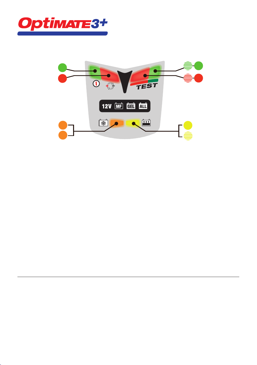
QUICK GUIDE – LED INFORMATION PANEL
Full details on any LED or step can be found in the manual under the same #
1
TEST MAINTAIN
55
2
ACTIVATE
DESULFATE
1. LED #1 - Power on. This LED confi rms AC power supply to the charger.
2. LED #2 indicates inverse polarity - wrong output connections. Swap around to activate output.
3. Circuit activation and recovery of deep-discharged, neglected batteries
3.1 ACTIVATION - If the battery voltage is above 2V, LED #3 lights briefl y to confi rm circuit activation.
For most batteries LED #3 goes out immediately and charge LED #4 comes on.
3.2 RECOVERY - For neglected or very fl at batteries, LED #3 remains on and indicates steadily.
If step 3 has not concluded after 2 hours, step 4 engages automatically.
4. Charge and charge verifi cation
4.1 CHARGE: A steady LED #4 indicates the bulk charge stage.
4.2 VERIFICATION: LED #4 fl ashes while the circuit verifi es battery charge level.
If the battery requires further charging the programme reverts to CHARGE. Multiple reversions may occur.
These reversions will cause LED #4 to alternate between steady and fl ashing, irregularly.
When LED #4 has fl ashed continuously for 30 minutes, step 5 engages and a voltage retention test starts.
5. 6. Voltage retention tests alternating half-hourly with battery maintenance
5. For a good battery LED #5 fl ashes throughout the 30 minute test. NO CHARGE CURRENT.
6. If the battery voltage falls below 12,4V during the test LED #6 (red) willcome on & indicate steadily.
Read § 6 in the main manual if LED #6 indicate in this period.
Maintenance - fl oat charge at a safe voltage limit to counter self-discharge.
Each test period is followed by a 30 minute maintenance charge period. Whichever LED (#5 fl ashing or #6 steady) was
indicating at the end of the TEST now indicates steadily. The battery can draw current as required to support small
loads & counter self-discharge.
Maintenance and voltage retention test periods continue alternating half-hourly until the battery is disconnected. The
test result is updated during each subsequent test.
3.1
3.2
66
4.1
CHARGE
VERIFY
4.2
LIMITED WARRANTY
Triumph Motorcycles Limited, Hinckley, Leicestershire LE10 3BS, England, makes this limited warranty to the original purchaser
at retail of this product. This limited warranty is not transferable. Triumph Motorcycles Limited warrants this battery charger
for two years from date of purchase at retail against defective material or workmanship. If such should occur the unit will
be repaired or replaced at the option of Triumph Motorcycles Limited. It is the obligation of the purchaser to forward the unit
together with proof of purchase, transportation or mailing costs prepaid, to the Triumph dealer from whom the unit was originally
purchased. This limited warranty is void if the product is misused, subjected to careless handling, or repaired by anyone other
than Triumph Motorcycles Limited’s authorized representative. Triumph Motorcycles Limited makes no warranty other than this
limited warranty and expressly excludes any implied warranty including any warranty for consequential damages.
THIS IS THE ONLY EXPRESS LIMITED WARRANTY AND TRIUMPH MOTORCYCLES LIMITED NEITHER ASSUMES NOR
AUTHORIZES ANYONE TO ASSUME OR MAKE ANY OTHER OBLIGATION TOWARDS THE PRODUCT OTHER THAN THIS
EXPRESS LIMITED WARRANTY. YOUR STATUTORY RIGHTS ARE NOT AFFECTED.
TM157-IN2-080701
Page 3

AUTOMATIC CHARGER FOR 12V LEAD/ACID BATTERIES.
Recommended for batteries of from 2 to 35Ah capacity. Do not use for NiCd, NiMH, Li-Ion or
non-rechargeable batteries. Input: 220-240V~ 0,075A. Output: 0,6A 9W (max).
IMPORTANT: READ THE FOLLOWING FULL INSTRUCTIONS FOR USE BEFORE USING THE CHARGER.
SAFETY WARNING AND NOTES: Batteries emit EXPLOSIVE GASES - prevent fl ame or sparks near batteries.
Disconnect AC power supply before making or breaking DC/battery connections. Battery acid is highly corrosive. Wear
protective clothing and eyewear and avoid contact. In case of accidental contact, wash immediately with soap and
water. Check that the battery posts are not loose; if so, have the battery professionally assessed. If the battery posts
are corroded, clean with a copper wire brush; if greasy or dirty clean with a rag damped in detergent. Use the charger
only if the input and output leads and connectors are in good, undamaged condition. If the input cable is damaged,
it is essential to have it replaced without delay by the manufacturer, his authorised service agent or a qualifi ed
workshop, to avoid danger. Protect your charger from acid and acid fumes and from damp and humid conditions both
during use and in storage. Damage resulting from corrosion, oxidation or internal electrical short-circuiting is not
covered by warranty. Distance the charger from the battery during charging to avoid contamination by or exposure
to acid or acidic vapours. If using it in the horizontal orientation, place the charger on a hard, fl at surface, but NOT on
plastic, textile or leather. Otherwise use the fi xing holes provided in the enclosure base to attach the charger to any
convenient, sound vertical surface.
EXPOSURE TO LIQUIDS: When placed on a horizontal fl at surface this charger is designed to withstand exposure
to liquids accidentally spilled or splashed onto the casing from above, or to light rainfall. Do not allow liquid to
accumulate below or around the base of the charger. Prolonged exposure to falling rain is inadvisable and longer
service life will be obtained by minimizing such exposure. Failure of the charger due to oxidation resulting from the
eventual penetration of liquid into the electronic components is not covered by warranty. Never expose connectors or
plugs to rain or snow.
BATTERY CONNECTIONS: 2 sets of interchangeable connection sets are supplied to connect the battery to the
charger. One has crocodile clamps for charging the battery off-vehicle, the other has metal eyelets intended for
permanent connection to the battery posts, and a resealable rubber protective cap on the 2-pole connector at its
other extremity. When fi xed permanently to the vehicle’s battery, this connection set allows easy and sure connection
of the charger to maintain the battery on-vehicle. The resealable rubber cap should be closed whenever the charger
is disconnected and/or the vehicle is in use so as to protect the 2-pole connector from dirt and damp. Consult a
professional service agent for assistance in attaching the metal eyelets to the battery posts. Distance the polarised
two-pole connector (for connection to the charger) as far as possible from the battery and secure it so that it
cannot foul any moving part of the vehicle or be pinched or damaged by sharp edges. The in-line fuse in the eyelets
connection set protects the battery against such accidental shorting across positive and negative conductors. Replace
any burnt fuse only with a similar new fuse of identical type and 7,5A rating.
IMPORTANT NOTES:
1. When charging a car battery, or if using the battery clamps, fi rst disconnect and remove the battery from the
vehicle and place it in a well ventilated area.
2. If the battery is deeply discharged (and possibly sulphated), it is essential to disconnect the battery from the
vehicle before connecting the charger for a recovery attempt. The charger’s special recovery mode cannot
engage if it senses that the battery is still connected to a vehicle wiring circuit which effectively offers a lower
electrical resistance than the battery on its own. However, if the deep-discharged battery is not removed for
recovery, neither battery nor vehicle electronics will be damaged.
3. If nonetheless you intend to connect the charger to an automotive battery using the battery clips connection
set without fi rst disconnecting and removing the battery, connect fi rst to the battery terminal not connected to
the chassis, then the other battery clip to the chassis well away from the battery and fuel line. Do this before
connecting to the AC input. Always disconnect in reverse sequence.
Page 4

USING THE OPTIMATE™3+
The clauses below are numbered the same as the quick guide on the inside front cover.
1. and 2. Connections and input power
Connect the charger to the battery: RED clamp to POSITIVE (POS, P, +) terminal and BLACK clamp to NEGATIVE (NEG,
N,–) terminal. Now you are ready to start:
1. Connect the charger to a mains supply socket providing AC supply of 220 to 240V. The “POWER ON” LED #1
should illuminate. If not, check your AC supply and the connection to it.
2. If the INVERSE POLARITY LED #2 indicates, the battery connections are incorrect. The charger is electronically
protected so no damage will result, and the output will be disabled automatically. Disconnect the AC input,
swap the battery connections around, then restore the AC input power.
3. Circuit activation and recovery of deep-discharged, neglected batteries
For safety reasons, the OptiMate™ output will only switch on if a battery retaining at least 2V is correctly connected to
it and to a live 220-240V input. If these conditions are not met, only the POWER ON LED #1 will light on the LED panel.
3.1 Immediately the output circuit is activated, the orange DESULFATE LED #3 comes on very briefl y while the
3.2 If the battery is extremely fl at (deep-discharged or sulphated), the DESULFATE LED will continue to indicate
NOTE: A battery left deep-discharged for an extended period may develop permanent damage in one or more cells.
Such batteries may heat up excessively during charging. Stop charging any battery immediately if it is uncomfortably
hot to touch.
4. Charge and charge verifi cation
4.1 The BULK CHARGE stage (steady LED #4) delivers a constant current of about 0,6 Amps into the battery. This
4.2 CHARGE VERIFICATION (fl ashing LED #4): The charging voltage is now limited at 13,6V during 30 minutes
NOTE
Some sealed “MF” or “AGM” batteries that have been neglected may cause the programme to advance to the
CHARGE VERIFICATION stage (4.2) without proceeding through the bulk CHARGE stage (§ 4.1). The built-in diagnostics
will detect and correct this anomaly. The circuit will oscillate between bulk charge and verifi cation as described in § 4.2.
5. and 6.
Voltage retention tests alternating half-hourly with battery maintenance
The fi rst VOLTAGE RETENTION TEST period of 30 minutes follows § 4.2, thereafter a 30 minute MAINTENANCE period.
These 30 minute TEST and MAINTENANCE periods then alternate for as long as the battery remains connected.
Delivery of current to the battery is interrupted for 30 minutes during voltage retention test periods to allow the
battery to rest (thereby minimizing loss of water from the electrolyte) and to allow the circuit to monitor the battery’s
voltage decline to determine its ability to retain charge and deliver power.
5. For batteries with a good state of health the green LED #5 should fl ash at the start of the test period and
™
OptiMate
can, the yellow CHARGE LED #4 will almost immediately replace the DESULFATE LED.
for up to 2 hours while a special high voltage is applied to force a very small fi xed current into the battery in
a recovery attempt. The charge voltage is limited at a maximum 20V while the circuit attempts to deliver a
current of 200mA into the battery. Ths can continue for up to 2 hours maximum, or until the moment when the
automatic circuit judges that the battery can accept the normal charging programme. At this moment or in any
case after the maximum time limit of 2 hours has elapsed, the CHARGE mode (§ 4) will engage.
will cause the charging voltage to increase gradually. When it reaches 14,3V, the OptiMate
absorption and CHARGE VERIFICATION stage.
whilst the battery’s charge level is verifi ed. If the battery requires further charging the programme will revert to
the main CHARGING stage (§ 4.1) and yellow LED #4 will indicate steadily again. When the rising voltage again
signals that the battery is approaching full charge the circuit reverts to VERIFICATION and LED #4 resumes
fl ashing. These reversions may occur as many times as is necessary to reduce the battery’s current demand
below 200mA at 13,6V (which is consistent with a battery that has accepted as much charge as its basic
condition allows). As soon as the circuit has verifi ed that the charge is adequate (signaled by LED #4 having
fl ashed continuously and consistently for a full 30 minutes), the voltage retention test (see § 5) automatically
follows.
continue to fl ash for the full 30 minutes until the next 30 minute maintenance period commences, when the
LED indication reverts to steady.
checks whether the battery can be charged effectively by the normal multi-stage programme. If it
™
will start the
2
Page 5

6. If the battery remains in circuit with the vehicle’s electrical system, and accessories or lights impose an
electrical load on the battery, the green LED may give way to a steady red LED indication.
Remove the battery from the vehicle and reconnect the OptiMate. The charge programme will in due course
again arrive at a voltage retention test result. If the LED indication is again red, read the following note.
NOTE ON RED LED INDICATION #6: If the above test on a battery removed from the vehicle results in a red LED
indication, you are advised to take the battery to a professional service workshop equipped with a BatteryMate
motorcycle battery tester-charger ( www.batterymate.com ) or a TestMate
™
digital battery tester (www.testmate.com
™
), for a more thorough investigation. The red LED means that after being charged the battery’s voltage is not being
sustained or that despite recovery attempts the battery was irrecoverable. This may be due to a defect in the battery
itself, such as a short-circuited cell or total sulphation, or, in the case of a battery still connected to the vehicle’s
wiring system, the red LED #6 may be signalling a loss of current through deteriorated wiring or a degraded switch or
contact, or in-circuit current-consuming accessories. A sudden load such as the headlights being switched on while
the charger is connected can also cause the battery voltage to dip signifi cantly. Always remove the battery from the
vehicle, reconnect the OptiMate
FINAL NOTE ON THE VOLTAGE RETENTION TEST: This test is a strongly indicative but not necessarily a conclusive
test of battery condition, which can be more precisely established by using a TestMate
™
and allow it to proceed through its programme once more.
™
mini which tests 12V batteries
on the vehicle during cranking, as well as the charging system operation. Alternatively, contact a workshop as advised
above.
Automatic battery maintenance
The 30 minute fl oat charge maintenance periods follow and alternate with the 30 minute test periods during which
there is no charge current. This “50% duty cycle” prevents loss of electrolyte in sealed batteries and minimizes
gradual loss of water from the electrolyte in batteries with fi ller caps, and thereby contributes signifi cantly to
optimizing the service life of irregularly or seasonally used batteries. The circuit offers current to the battery within
a safe 13,6V voltage limit (“fl oat charge”), allowing it to draw whatever small current is necessary to sustain it at
(or close to) full charge and compensate for any small electrical loads imposed by vehicle accessories or on-board
computer, or the natural gradual self-discharge of the battery itself.
NOTE: Maintaining a battery for extended periods: After activating the charger you should observe the LED
indications every few hours until the test result is displayed. If at any time the battery is hot to touch, disconnect it
from the charger and get it professionally tested using a BatteryMate
™
or TestMate™ II electronic tester specifi cally
designed for that type of battery. At least once every two weeks, check that the connections between the charger and
battery are secure, and, in the case of batteries with fi ller caps on each cell, disconnect the battery from the charger,
check the level of the electrolyte and if necessary, top up the cells (with distilled water, NOT acid), then reconnect.
When handling batteries or in their vicinity, always take care to observe the SAFETY WARNINGS above.
Charging time
The time required for the OptiMate™3+ to complete a charge on a fl at but not severely discharged and otherwise
undamaged battery is roughly equal to the battery’s Ah rating, so a 12Ah battery should take no more than about 12
hours to progress to the self-discharge check (§ 5). Deep-discharged batteries may take signifi cantly longer.
NOTE: The total charging time of the above steps 4.1 and 4.2 is not limited.
™
If using the OptiMate
3+ on a severely discharged automobile battery of larger capacity than the recommended rated
capacity range (2 to 35Ah), a full charge may require up to several days. In such cases, prolonged continuous charger
operation at maximum output and in warm ambient temperatures may cause the charger to become quite hot. For
best charger servie life, it is recommended that you switch off and allow the charger to cool thoroughly to room
temperature before reconnecting it to complete the charge.
Disconnection
Disconnect the OptiMate™ fi rst from the AC mains supply and then from the battery. Always disconnect from the
AC mains before reconnecting to the same or another battery. Close the rubber cap on the eyelets connection lead
(TM-71) if this is attached to the battery, to protect its 2-pole connector against dirt and damp while the OptiMate
disconnected.
™
is
3
Page 6
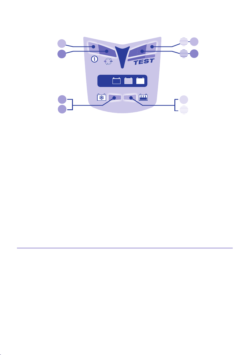
GUIDE RAPIDE – PANNEAU D’INFORMATION LED
Tous les details sur LEDs ou programme dans le manuel – mêmes numéros
1
ENTRETIENTEST
55
2
MF GEL
12V
ACTIVATION
DESULFATE
1. LED #1 - Marche. Cette LED confi rme la présence d’alimentation AC vers le chargeur.
2. LED #2 polarités inverses – connexions erronées en sortie. Corriger pour activation.
3. Activation de circuit et récupération de batteries fortement déchargées
3.1
3.2
ALL
66
CHARGE
4.1
VERIF.
4.2
3.1 ACTIVATION - Si le V batterie est > 2V, la LED #3 s’allume brièvement pour confi rmer l’activation.
Plupart des batteries : la LED #3 s’éteint de suite et la LED #4 s’allume.
3.2 RÉCUPÉRATION - pour batteries négligées ou « à plat ». La LED 3 reste allumée en fi xe.
Si l’étape 3 n’a pas été fructueuse après 2h, l’étape 4 s’engage automatiquement.
4. Charge et vérifi cation de charge
4.1 CHARGE : La LED #4 allumée en fi xe indique l’étape de charge principale.
4.2 VÉRIFICATION : LA LED #4 clignote alors que le circuit vérifi e le niveau de charge. Si la batterie requiert plus de
charge, le programme repasse en mode CHARGE. Plusieurs retours possibles. Les réversions font que la LED
#4 alterne de façon irrégulière entre un état fi xe ou clignotant.
Si la LED# 4 a clignoté durant 30 minutes d’affi lée (ou si les étapes 3 + 4 n’ont pas été achevées sous 48h),
l’étape 5 s’engage et un test de rétention de voltage commence.
5. 6. Tests de rétention et entretien de batterie – alternance toutes les 30 min.
5. Si batterie en bon état, la LED #5 clignote durant les 30 minutes de test. PAS DE COURANT DE CHARGE.
6. La LED # 6 (état fi xe) peut remplacer la # 5 si le voltage de batterie chute durant le test.
Lisez les§ 6 dans le manuel si la LED 6 s’allume durant cette période.
Entretien - charge fl ottante sous voltage sûr pour prévenir toute décharge.
Durant les périodes d’entretien de 30 minutes, la LED #5 (ou #6) s’allume alors de façon fi xe. La batterie prend le
courant nécessaire pour compenser les pertes et consommations.
Les périodes de test et d’entretien continuent d’alterner toutes les 1/2h jusqu’à déconnexion. Le résultat de test
est réactualisé à chaque fois.
GARANTIE LIMITÉE
Triumph Motorcycles Limited, Hinckley, Leicestershire LE10 3BS, England, consent la présente garantie au premier
client utilisateur de ce produit, sans possibilité de transfert. Triumph Motorcycles Limited garantit ce chargeur pendant
deux ans à compter de la date d’achat au détail contre les défauts de composants ou d’assemblage. Le cas échéant,
le chargeur sera réparé ou remplacé à la discrétion de Triumph Motorcycles Limited. L’acheteur doit expédier, à ses
frais, l’appareil ainsi qu’une preuve d’achat au concessionnaire Triumph agréé. Cette garantie limitée devient nulle
si l’appareil est utilisé ou manipulé de façon inadéquate ou s’il a été réparé par toute personne physique ou morale
autre que le représentant agréé de Triumph Motorcycles Limited. Triumph Motorcycles Limited n’offre aucune autre
garantie que la présente, et exclut expressément toute garantie contre les dommages conséquentiels.
CECI EST LA SEULE GARANTIE EXPRESSÉMENT CONSENTIE PAR TRIUMPH MOTORCYCLES LIMITED. CELUI-CI
N’ASSUME ET N’AUTORISE QUICONQUE A ASSUMER OU ETABLIR TOUTE AUTRE OBLIGATION LIÉE À CE PRODUIT,
AUTRE QUE CETTE GARANTIE LIMITÉE EXPRESSÉMENT CONSENTIE.
4
Page 7

CHARGEUR-DIAGNOSTIC AUTOMATIQUE POUR BATTERIES
PLOMB-ACIDE 12V.
Recommandé pour modèles 2-35 Ah. Incompatible avec piles non-rechargeables, NiCd, NiMH, Li-Ion.
Alimentation : 220-240V~ 0,075A. Sortie 0,6A 9W (maximum).
IMPORTANT : LIRE COMPLÈTEMENT CE MODE D’EMPLOI AVANT D’UTILISER L’APPAREIL.
AVERTISSEMENT DE SÉCURITÈ ET NOTES : Batterie = présence de GAZ EXPLOSIFS – évitez étincelles et
fl ammes à proximité. Débranchez la prise 220V-240V avant d’établir/supprimer une connexion à la batterie. L’acide
de batterie est hautement corrosif. Portez des vêtements protecteurs et évitez tout contact. Contact accidentel : lavez
avec de l’eau et du savon. Les bornes de la batterie ne doivent pas être lâches, sinon faites-les contrôler par un
professionnel. Si elles sont corrodées, utilisez une brosse en chiendent ; si elles sont sales ou graisseuses, utilisez un
chiffon et du détergent. N’utilisez le chargeur que si sa connectique est en parfait état. Si le câble d’alimentation est
endommagé, faites-le remplacer par le fabricant, son distributeur, ou autre atelier qualifi é. Protégez votre chargeur
de l’humidité, acide, et vapeurs acides durant l’utilisation et l’entreposage. Tout dommage engendré par la corrosion,
l’oxydation ou un court-circuit interne ne sera pas couvert par la garantie. Eloignez la batterie du chargeur pendant la
charge pour éviter toute exposition à l’acide et à ses vapeurs. Si utilisé en position horizontale, placez le chargeur sur
une surface plane et dure, mais PAS sur une surface plastique, textile, ou en cuir. Vous pouvez également utiliser les 4
orifi ces situés aux extrémités du chargeur afi n de le fi xer sur toute surface verticale adéquate.
EXPOSITION À DES LIQUIDES : en utilisation horizontale (surface plane), ce chargeur est conçu pour résister à
l’exposition aux liquides qui tomberaient accidentellement sur le boîtier, ou à une pluie légère. Toutefois, ne jamais
laisser aucun liquide s’accumuler sous ou autour de la base. Une exposition prolongée à des liquides tombants ou à
la pluie est à déconseiller. Une durée de vie supérieure résultera d’une telle précaution. Une panne due à l’oxydation
résultant d’une pénétration de liquide dans les composants électroniques ne sera pas couverte par la garantie. Ne
jamais exposer aucun élément de connexion à la pluie ou à la neige.
CONNEXION À UNE BATTERIE : 2 sets de connexion interchangeables sont fournis. Un set avec pinces crocodiles
pour une charge hors-véhicule, l’autre avec œillets en métal pour une connexion à demeure sur les bornes de
la batterie et, à l’autre extrémité, un capuchon refermable en caoutchouc protégeant le connecteur bipolaire. Ce
deuxième set permet une connexion sûre et aisée pour un maintien de batterie alors que celle-ci est elle-même
connectée au véhicule. Le capuchon en caoutchouc doit être refermé lorsque le chargeur est déconnecté et/ou
avant d’utiliser le véhicule, de façon à protéger le connecteur bipolaire de la saleté et de l’humidité. Faites appel à
une assistance professionnelle pour la fi xation des œillets métalliques aux bornes de la batterie. Eloignez autant que
possible le connecteur bipolaire de la batterie et assurez-vous qu’il ne puisse se prendre dans aucune pièce mobile
du véhicule ou être pincé ou endommagé par des parties tranchantes. Le fusible en ligne monté sur le set à oeillets
est là pour protéger la batterie dans de tels cas de court-circuit entre les conducteurs positif et négatif. Remplacez
toujours le fusible par un modèle identique, de 7,5A.
NOTES IMPORTANTES :
1. Lorsque vous chargez une batterie de voiture ou si vous utilisez le set à pinces, déconnectez et ôtez d’abord la
batterie du véhicule et placez-la dans un endroit bien ventilé.
2. Si la batterie est profondément déchargée (et éventuellement sulfatée), il est essentiel de la déconnecter du
véhicule avant d’y connecter le chargeur pour une tentative de récupération. Le mode spécial de récupération
ne peut s’initialiser s’il détecte que la batterie est toujours connectée à un faisceau électrique de véhicule,
celui-ci offrant une résistance électrique inférieure à celle de la batterie seule. Toutefois, si la batterie en état
de décharge profonde n’est pas démontée du véhicule lors de la tentative de récupération, ni la batterie ni
l’électronique embarquée du véhicule ne seront endommagées.
3. Si vous désirez toutefois connecter le chargeur à une batterie automobile en utilisant les pinces de charge
et sans déconnecter et démonter la batterie au préalable, connectez d’abord une pince à la borne non reliée
au châssis, puis l’autre pince au châssis, bien éloignée de la batterie et de l’alimentation en carburant. Ne
connecter au réseau qu’ensuite. Déconnectez toujours dans l’ordre inverse.
5
Page 8

UTILISER L’OPTIMATE™3+
Les points ci-dessous sont numérotés de la même façon que le guide rapide ci-avant.
1. et 2. Connexions et Alimentation
Connectez le chargeur à la batterie : la pince ROUGE à la borne POSITIVE (POS, P, +), la pince NOIRE à la borne
NÉGATIVE (NEG, N,–). Vous êtes maintenant prêt à commencer :
1. Connectez le chargeur à une prise réseau CA fournissant de 220 à 240V. La LED d’alimentation (#1) doit
s’allumer. Sinon, contrôlez la prise réseau et la connexion.
2. Si la LED d’inversion de polarités s’allume, les connexions à la batterie sont erronées. Le chargeur est protégé
contre cette erreur, aucun dommage n’est à craindre – désactivation automatique. Déconnectez l’alimentation,
inversez les connexions à la batterie et reconnectez l’alimentation.
3.
Activation du circuit et récupération de batteries fortement déchargées / négligées
Pour des raisons de sécurité, pour initialiser son circuit de sortie, l’OptiMate™ doit être connecté au réseau 220-240V
AC et doit détecter qu’une batterie ayant au moins 2V est connectée. Si ces conditions ne sont pas remplies, seule la
LED d’alimentation (#1) s’allumera.
3.1 Dès l’activation du circuit de sortie, la LED orange #3 (DÉSULFATATION) s’allume brièvement et l’OptiMate
vérifi e si la batterie peut être chargée de façon effi cace par le programme à étapes multiples. Si c’est le cas, la
LED de CHARGE jaune (#4) remplacera la LED orange.
3.2 Si la batterie est « à plat » (fortement déchargée ou sulfatée), la LED DESULFATE peut rester allumée durant 2
heures max. et un voltage élevé sera appliqué pour forcer un petit courant dans la batterie afi n de la récupérer.
Durant cette période, le voltage est limité à 20V. Le circuit évalue la probabilité de récupération de la batterie
sous cette tension. Si et dès que la batterie est à même d’accepter le petit courant, le voltage se réduira
automatiquement jusqu’à ce que la batterie puisse être à nouveau chargée par le programme normal. A ce
moment, et de toute façon après deux heures au plus, le mode de charge normal s’activera (§4).
NOTE : Une batterie fortement déchargée depuis longtemps peut avoir subi des dommages irréversibles dans une ou
plusieurs cellules. De telles batteries pourraient surchauffer durant la charge ; il faut stopper celle-ci immédiatement
si une batterie devenait exagérément chaude au toucher.
4. Charge et vérifi cation de charge
4.1 Etape de CHARGE principale (LED 4 fi xe) : un courant constant de 0,6A est délivré, provoquant une montée de
voltage graduelle dans la batterie. Lorsque celui-ci atteint 14,3V, l’OptiMate
VÉRIFICATION DE CHARGE.
4.2 VÉRIFICATION DE CHARGE (LED 4 clignotante) : le voltage de charge est maintenant limité à 13,6V durant 30
minutes alors que le niveau de charge est vérifi é. Si la batterie nécessite davantage de charge, le programme
repassera en mode de CHARGE principal (§ 4.1) et la LED jaune #4 se rallumera en fi xe. Dès que le voltage
aura à nouveau remonté, signalant l’approche de la pleine charge, le circuit repasse en VÉRIFICATION et la
LED #4 recommence à clignoter. Ces réversions auront lieu autant de fois que nécessaire afi n de réduire la
demande de courant émanant de la batterie à moins de 200mA à 13,6V (valeurs typiques pour une batterie
qui a accepté autant de charge que son état initial le permettait). Dès que le circuit a constaté que la charge
est adéquate (la LED #4 ayant clignoté en continu durant 30 minutes pleines), le test de rétention de voltage
commence (§ 5).
NOTE Certaines batteries MF-AGM qui auraient été négligées pourraient entraîner l’avancement du programme à
l’étape de VÉRIFICATION (4.2) sans passer par la charge principale (§ 4.1). Le système de diagnostic détectera et
corrigera cette anomalie. Le circuit oscillera entre les modes de charge et de vérifi cation, comme décrit dans le § 4.2.
™
active l’étape d’absorption et de
5. et 6.
Alternance entre tests de rétention de voltage et maintien chaque demi heure
La première période de TEST de RÉTENTION DE VOLTAGE de 30 minutes suit le § 4.2 ; s’ensuit une période de
MAINTIEN. Ces périodes de TEST et MAINTIEN alternent ensuite aussi longtemps que la batterie reste connectée. La
délivrance de courant à la batterie est interrompue durant 30 minutes pour l’étape de test, ce qui permet à la batterie
de se reposer (minimisant ainsi les pertes d’eau de l’électrolyte). Le circuit surveille le déclin de voltage de la batterie
afi n de déterminer son aptitude à retenir une charge et à délivrer de la puissance.
5. Batteries en bon état : la LED verte (#5) clignotera durant toute la période de test, et passera en fi xe lorsque
le mode de maintien s’activera. Si la batterie reste connectée au véhicule et qu’elle est soumise à une
™
6
Page 9

consommation (lampes, accessoires etc), la LED verte (clignotante) pourrait être remplacée par la LED rouge
(fi xe) durant la période de test.
6. Normalement, la LED rouge signale une batterie défectueuse. Mais il peut se produire qu’une batterie en bon
état et qui est restée connectée au véhicule subisse un résultat de test mauvais, à cause d’une consommation
de courant excessive par des accessoires ou d’une perte de courant dans le faisceau électrique du véhicule.
Ôtez la batterie du véhicule et reconnectez l’OptiMate. Si un meilleur résultat (LED verte) est alors atteint,
le problème provient sans doute du faiseau électrique du véhicule. Par contre si la LED rouge s’allume de
nouveau pendant le test, la batterie est probablement défectueuse. Lisez le NOTE supplémentaire.
NOTE SUPPLÉMENTAIRE SUR LA LED ROUGE #6 : Si le test sur batterie hors-véhicule donne encore un résultat
de LED rouge, nous vous conseillons de faire vérifi er la batterie chez un professionnel équipé d’un chargeur-testeur
BatteryMate
™
( www.batterymate.com ) ou d’un testeur digital TestMate™ (www.testmate.com ) pour un test
approfondi. La LED rouge signifi e qu’après avoir été chargée, le voltage de la batterie n’a pu rester à un niveau
acceptable, ou qu’elle s’est révélée irrécupérable malgré l’étape de désulfatation. Ceci est peut-être dû à un défaut
de la batterie elle-même, comme un court-circuit interne ou une sulfatation totale ou, dans le cas d’une batterie
restée connectée à un véhicule, la LED rouge (6) pourrait signaler une perte de courant sur un faisceau défaillant, un
interrupteur ou contact dégradé, ou encore la présence d’accessoires consommant du courant. Une consommation
soudaine comme l’allumage des phares alors que le chargeur est connecté peut aussi entraîner une chute de voltage
signifi cative. Ôtez la batterie dans tous les cas, reconnectez l’OptiMate
™
et recommencez le programme.
NOTE FINALE SUR LE TEST DE RÉTENTION DE VOLTAGE : Ce test a un caractère fortement indicatif mais pas
nécessairement conclusif quant à l’état d’une batterie donnée, celui-ci pouvant être établi avec plus de précision à
l’aide du TestMate
charge interne. L’on peut également contacter un professionnel équipé d’un BatteryMate
™
mini, qui peut tester une batterie 12V sur véhicule durant le démarrage ainsi que le système de
™
150-9 ou d’un TestMate™
digital.
Maintenance de batterie automatique
Les périodes de maintenance de 30 minutes suivent et alternent avec les périodes de test de même durée, au cours
desquelles aucun courant n’est délivré. Ce cycle « à 50% » permet aux batteries de se « reposer » chaque demi heure
et de minimiser les pertes d’eau par évaporation, dans le cas de batteries à bouchons. Il en résulte une optimisation
signifi cative de la durée de vie de batteries à usage irrégulier ou saisonnier. Le circuit offre du courant à la batterie
sous une limite sûre de 13,6V (charge « fl ottante »), permettant à la batterie de « tirer » tout petit courant nécessaire
à son maintien en état de pleine charge (ou proche) et de compenser les consommations dues à des accessoires
comme système anti-vol, ordinateur de bord etc, ou à l’auto-décharge graduelle de la batterie elle-même.
NOTE : Maintenances prolongées : Après l’activation du chargeur, il est conseillé d’observer les indications LED de
temps à autre jusqu’à affi chage du résultat. Si la batterie devient chaude au toucher à quelque moment que ce soit,
déconnectez-la du chargeur et faites-la tester par un professionnel équipé d’un BatteryMate
™
TestMate
II, spécifi quement développé pour les batteries de motos. Au moins une fois toutes les deux semaines,
™
ou d’un testeur digital
vérifi ez que les connexions entre le chargeur et la batterie soient franches et, s’il s’agit d’un modèle à bouchons,
déconnectez du chargeur, contrôlez les niveaux d’électrolyte et faites l’appoint si nécessaire (avec de l’eau distillée,
PAS avec de l’acide). Ensuite, reconnectez. Lorsque vous manipulez des batteries ou êtes à proximité, veillez à
observer les AVERTISSEMENTS DE SÉCURITÉ ci-dessus.
Temps de charge
Le temps requis par l’OptiMate™3+ si la batterie est complètement déchargée mais toutefois en bon état, est environ
égal à la capacité de la batterie en Ah. Il faudra donc à peu près 12 heures pour qu’une batterie de 12Ah soit amenée
au stade de contrôle de charge fi nal (§ 5). Les batteries en état de décharge profonde peuvent prendre beaucoup plus
de temps.
NOTE : Le temps de charge total des étapes 4.1 et 4.2 n’est pas limité. Si vous rechargez une batterie auto
sévèrement déchargée à l’aide de l’OptiMate
™
3+, il est probable qu’une pleine charge ne puisse être atteinte même
après quelques jours. Il se peut que durant ces journées de travail à pleine charge, le chargeur soit devenu fort
chaud. Mieux vaut alors le laisser au repos jusqu’à ce qu’il soit revenu à la température ambiante avant de relancer la
charge.
Déconnexion
Déconnectez d’abord l’OptiMate™ du réseau AC puis de la batterie. Il faut toujours agir dans cet ordre avant de le
reconnecter à une batterie – la même ou une autre. Refermez le capuchon en caoutchouc sur l’embout du connecteur
à demeure (TM-71) qui pourrait être connecté à la batterie, afi n de le protéger de l’humidité et des impuretés.
7
Page 10
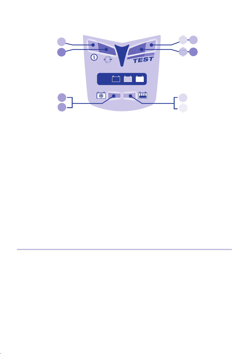
KURZANLEITUNG – LED-INFORMATIONSFELD
Einzelheiten über LEDs oder Stufen sind im Handbuch unter der entsprechenden Nummer zu fi nden.
1
WARTUNGTEST
55
2
MF GEL
12V
AKTIVIEREN
DESULFATIEREN
1. LED #1 - Power on. Diese LED zeigt an, dass das Ladegerät mit Wechselstrom versorgt wird.
2. LED #2 zeigt falsche Ausgangsanschlüsse an. Anschlüsse tauschen, um den Ausgang zu aktivieren.
3. Aktivierung der Schaltung und erholung tiefentladener, vernachlässigter Batterien.
3.1
3.2
ALL
66
LADEN
4.1
PRÜFEN
4.2
3.1 Liegt die Batteriespannung über 2V, leuchtet LED #3 kurz auf, um die Aktivierung der Schaltung zu bestätigen.
Bei den meisten Batterien erlischt LED #3 sofort und die Lade-LED #4 leuchtet.
3.2 ERHOLUNG: bei vernachlässigten oder stark entladenen Batterien leuchtet LED #3 ständig.
Ist Stufe 3 nach 2 Stunden nicht abgeschlossen, wird Stufe 4 automatisch eingeleitet.
4. Laden und überprüfen der Ladung.
4.1 LADEN: eine ständig leuchtende LED #4 zeigt die Grundladephase an.
4.2 ÜBERPRÜFUNG: LED #4 blinkt, während die Schaltung den Ladezustand der Batterie überprüft. Wenn die Batterie weiter
geladen werden muss, wechselt das Programm wieder auf laden. Mehrere derartige Wechsel können auftreten. Diese
Wechsel können dazu führen, dass LED #4 unregelmäßig zwischen dauerndem Leuchten und Blinken wechseln können.
Wenn LED #4 ununterbrochen 30 Minuten geblinkt hat (oder wenn die Stufen 3 + 4 nicht innerhalb von 48 Stunden
abgeschlossen ist) wird Stufe 5 eingeleitet und eine Spannungshalteprüfung beginnt.
5. 6. Spannungshalteprüfung wechselt halbstündlich mit Batteriewartung.
5. Bei einer intakten Batterie blinkt LED #5 während des 30-minütigen Tests. Kein Ladestrom.
6. Daurende LED #6 kann LED #5 ersetzen, wenn die Batteriespannung während des Tests abfällt.
Lesen sie § 6 in der eigentlichen A
Wartung – fl oat-Ladung bei sicherem Spannungslimit, um der Selbstentladung entgegenzuwirken.
Während der 30-minütigen Wartungsladungsperioden leuchtet/leuchten die LED(s) #5 / #6 ständig. Die Batterie kann nach bedarf
Strom aufnehmen, um kleinere Belastungen zu verkraften und der Selbstentladung entgegenzuwirken. .
Die Wartungs- und die Spannungshalteprüfperiode wechseln einander halbstündlich ab, bis die Batterie
abgeklemmt wird. Das Testergebnis wird bei jeder weiteren Prüfung aktualisiert.
nleitung, wenn LED #6 während dieses Zeitraums aufl euchtet.
BEGRENZTE GARANTIE
Triumph Motorcycles Limited, Hinckley, Leicestershire LE10 3BS, England, gewährt dem ursprünglichen Käufer beim
Kauf dieses Produktes diese begrenzte Garantie. Diese begrenzte Garantie ist nicht übertragbar. Triumph Motorcycles
Limited übernimmt für zwei Jahre ab Verkaufsdatum die Garantie für dieses Batterieladegerät hinsichtlich Materialoder Verarbeitungsfehlern. Sollten solche Fehler auftreten, wird das Gerät nach Ermeßen Triumph Motorcycles Limited
repariert oder ersetzt. Es ist Sache des Käufers, das Gerät zusammen mit dem Kaufnachweis an den ermächtigten
Triumph Vertreter einzuschicken, wobei der Käufer die Transport- oder Portokosten trägt. Diese begrenzte Garantie
ist nichtig, wenn das Produkt mißbräuchlich verwendet, unsachgemäß behandelt oder nicht vom Werk oder einem
von Triumph ermächtigten Vertreter repariert wurde. Triumph Motorcycles Limited gewährt außer dieser begrenzten
Garantie keinerlei Garantie und schließt ausdrücklich jede implizite Gewährleistung, einschließlich jeglicher Garantie
gegen Folgeschäden aus.
DIES IST DIE EINZIGE AUSDRÜCKLICHE BEGRENZTE GARANTIE, UND TRIUMPH MOTORCYCLES LIMITED ÜBERNIMMT
KEINERLEI VRPFLICHTUNG GEGENÜBER DEM PRODUKT.
8
Page 11

AUTOMATISCHES DIAGNOSE-LADEGERÄT FÜR 12V BLEIAKKUS.
Empfohlen für Batterien mit Kapazitäten von 2 bis 35Ah. Nicht verwenden für NiCd, NiMH, Li-Ion oder nicht
aufl adbare Batterien. Eingang: 220-240V~ 0,075A. Ausgang: 0,6A 9W (max.)
WICHTIG: LESEN SIE VOR GEBRAUCH DES LADEGERÄTS DIE FOLGENDEN ANWEISUNGEN VOLLSTÄNDIG.
ACHTUNG!
von Batterien. Trennen Sie das Ladegerät vom Netz, bevor Sie Batterien an das Gerät anschließen, oder von ihm
trennen. Batteriesäure ist stark ätzend. Tragen Sie Schutz-Kleidung und vermeiden Sie Kontakt. Waschen Sie sich bei
versehentlichem Kontakt sofort mit Wasser und Seife. Vergewissern Sie sich, daß die Endpole der Batterie nicht lose
sind. Ist dies der Fall, lassen Sie die Batterie von einem Fachmann inspizieren. Korrodierte Endpole müssen mit einer
Kupferdrahtbürste gesäubert werden; sind die Pole fettig oder schmutzig, sollten sie mit einem in Reinigungsmittel
getränkten Lappen gereinigt werden. Verwenden Sie das Ladegerät nur, wenn Zuleitungen und Anschlüsse in
einwandfreiem Zustand sind. Wenn die Anschlußleitung dieses Gerätes beschädigt wird, muß sie durch den Hersteller
oder seinen Kundendienst oder eine ähnlich qualifi zierte Person ersetzt werden, um Gefährdungen zu vermeiden.
Schützen Sie Ihr Ladegerät bei der Verwendung und bei der Lagerung vor Feuchtigkeit, Nässe und Säure.
Das Ladegerät von der Batterie so weit wie möglich distanzieren und auf einer festen, ebenen Oberfl äche
setzen, aber bringen Sie mittels der Befestigungsöffnungen im Gehäuseboden das Ladegerät an einer
geeigneten, stabilen senkrechten Fläche an.
AUSGESETZTSEIN ZU DEN FLÜSSIGKEITEN: Wenn Sie auf eine horizontale fl ache Oberfl ache gesetzt wird, ist
dieses Ladegerät konstruiert, um Ausgesetztsein zu den Flüssigkeiten, die versehentlich auf das Gehäuse von oben
verschüttet werden oder gespritzt sind, oder zum Nieselregen, zu widerstehen. Jedoch ist verlängertes Ausgesetztsein
nicht ratsam und längere Lebensdauer wird erreicht, indem man solches Ausgesetztsein minimiert. Ausfall des
Gerätes wegen der Oxidation, die aus dem etwaigen Durchgriff der Flüssigkeit in die elektronischen Bauelemente
resultiert, wird nicht durch Garantie abgedeckt.
ANSCHLUSSHINWEISE: Um das Ladegerät an die Batterie anzuschließen, werden 2 austauschbare Batterie-
Anschlusskabel mit dem Gerät geliefert : das eine mit Ösen wie fest an den Batteriepolen befestigt bleiben für
eine Schnellverbindung des Ladegerät, das andere mit Krokodilklemmen. Vergewissen Sie sich daß die polarisierte
zweipolige Verbinder und Kabel von der Batterie fort weist und nicht mit beweglichen Teilen des Fahrzeuges
in Berührung kommen kann. Die Sicherung des Batterie-Anschlusskabel mit Ösen schützt die Batterie gegen
unbeabsichtigtem Kurzschluß über den positiven und den negativen Leiter. Ersetzen Sie eine durchgebrannte
Sicherung nur durch eine gleiche Sicherung, T 7,5A. Verhindern Sie das Eindringen der Schmutz in den polarisierten
Verbinder durch schließen des Gummiverschluß wenn Sie das Ladegerät von der Batterie abtrennen.
WICHTIGE HINWEISE:
BATTERIEN SONDERN EXPLOSIVE GASE AB: vermeiden Sie Flammen oder Funken-Bildung in der Nähe
1. Beim Laden einer Autobatterie oder bei Benutzung der Batterieklemmen muss die Batterie zunächst
abgeklemmt, aus dem Fahrzeug ausgebaut und in einem ausreichend belüfteten Bereich aufgestellt werden.
2. Wenn die Batterie tiefentladen (und möglicherweise sulfatiert ist), muss sie unbedingt vom Fahrzeug
abgeklemmt werden, bevor das Ladegerät angeschlossen wird, um einen Rettungsversuch zu unternehmen.
Der spezielle Erholungsmodus des Ladegeräts kann nicht aktiviert werden, wenn das Ladegerät erkennt, dass
die Batterie noch mit der Elektrik eines Fahrzeugs verbunden ist, die einen niedrigeren elektrischen Widerstand
darstellt, als die Batterie für sich. Wenn dagegen die tiefentladene Batterie nicht zwecks Wiederherstellung
ausgebaut wird, nehmen weder die Batterie, noch die Fahrzeugelektronik Schaden.
3. Sollten Sie dennoch vorhaben, das Ladegerät mittels des Batterieklemmen-Anschluss-Sets an eine Autobatterie
anzuschließen, schließen Sie es zuerst an den Batteriepol an, der nicht mit dem Chassis verbunden ist,
und anschließend die andere Klemme an das Chassis, in ausreichender Entfernung von Batterie und
Kraftstoffl eitung. Tun Sie dies vor dem Anschließen an den Wechselstromeingang. Beim Abklemmen immer in
umgekehrter Reihenfolge verfahren.
9
Page 12

BENUTZUNG DES OPTIMATE™3+
Die folgenden abschnitte sind auf die gleiche weise nummeriert, wie in der kurzanleitung innen auf der vorderen
umschlagseite.
1. und 2. Anschlüsse und Eingangsstrom
Verbinden Sie das Ladegerät mit der Batterie: ROTE Klemme an PLUSPOL (POS, P, +) und SCHWARZE Klemme an MINUSPOL
(NEG, N,–). Nun können Sie beginnen:
1. Schließen Sie das Ladegerät an eine Netzsteckdose mit 220 bis 240V Wechselstromversorgung an. Die LED #1 “POWER
ON” sollte leuchten. Wenn nicht, prüfen Sie Wechselstromversorgung und Anschluss.
2. Wenn die LED #2 “UMGEKEHRTE POLARITÄT” leuchtet, ist die Batterie falsch angeschlossen. Das Ladegerät ist
elektronisch geschützt, sodass kein Schaden eintritt, der Ausgang wird automatisch deaktiviert. Klemmen Sie den
Wechselstromeingang ab, vertauschen Sie die Batterieverbindungen und stellen Sie die Wechselstromzufuhr wieder her.
3. Aktivierung der Schaltung und Erholung Tiefentladener, vernachlässigter Batterien.
Aus Sicherheitsgründen schaltet sich der der Ausgang des OptiMate™ nur ein, wenn eine Batterie mit mindestens 2V
Restspannung korrekt an den Ausgang angeschlossen und das Ladegerät an eine Spannung führende 220-240V Steckdose
angeschlossen ist. Sind diese Bedingungen nicht erfüllt, leuchtet nur die LED #1 “POWER ON” auf dem LED-Feld.
3.1 Sofort nach Aktivierung des Ausgangsschaltkreises leuchtet die orangefarbene LED #3 “DESULFATIEREN” kurz auf,
während der OptiMate
dies der Fall, löst die gelbe LED #4 “LADEN” fast augenblicklich die LED “DESULFATIEREN” ab.
3.2 Ist die Batterie in extrem schlechten Zustand (tiefentladen oder sulfatiert), leuchtet die LED “DESULFATIEREN” bis
zu 2 Stunden weiter, während eine spezielle hohe Spannung angelegt wird, um die Batterie mit einem sehr kleinen,
festgelegten Strom zu versorgen und so den Versuch zu unternehmen, sie zu retten. Die Spannungsgrenze wird auf 20V
gesetzt, der Strom wird jedoch auf einen sehr niedrigen, sicheren Wert begrenzt, bis die Schaltung erkennt, dass die
Batterie das normale Ladeprogramm aufnehmen kann. Zu diesem Zeitpunkt, bzw. nach Anlauf des maximalen Zeitlimits
von 2 Stunden, wird der LADEMODUS (§ 4) aktiviert.
HINWEIS: Bei einer Batterie, die sich über einen längeren Zeitraum im tiefentladenen Zustand befand, können eine oder mehrere
Zellen permanent beschädigt sein. Solche Batterien können sich beim Laden übermäßig erwärmen. Batterien, die so heiß werden,
dass eine Berührung unangenehm ist, dürfen nicht weiter geladen werden.
4. Laden und Überprüfen der Ladung
4.1 Die GRUNDLADEPHASE (LED #4 leuchtet permanent) versorgt die Batterie mit einem Konstantstrom von rund 0,6 Ampere.
Die Ladespannung wird dadurch veranlasst, allmählich zu steigen. Wenn sie 14,3V erreicht, leitet der OptiMate
Absorptions- und die LADUNGSÜBERPRÜFUNGSPHASE ein.
4.2 LADUNGSÜBERPRÜFUNG (LED #4 blinkt): Die Ladespannung wird nun 30 Minuten lang auf 13,6V begrenzt, während
der Ladezustand der Batterie überprüft wird. Wenn die Batterie weitere Ladung benötigt, kehrt das Programm zur
Hauptladephase zurück (§ 4.1) und die gelbe LED #4 leuchtet wieder ununterbrochen. Wenn die steigende Spannung
wieder signalisiert, dass sich die Batterie der vollen Ladung nähert, wechselt die Schaltung wieder zur ÜBERPRÜFUNG
und LED #4 beginnt wieder zu blinken. Diese Programmwechsel können so häufi g auftreten, wie erforderlich, um
den Strombedarf der Batterie auf unter 200mA bei 13,6V zu reduzieren (was einer Batterie entspricht, die so viel
Ladung aufgenommen hat, wie ihr Grundzustand zulässt). Sobald die Schaltung ermittelt hat, dass die Ladung
ausreichend ist (dadurch signalisiert, dass LED #4 30 Minuten lang ständig und einheitlich blinkt), folgt automatisch die
Spannungshalteprüfung (siehe § 5).
HINWEIS Bei einigen vernachlässigten versiegelten “MF” oder “AGM” Batterien kann das Programm veranlasst werden, zur Phase
LADUNGSÜBERPRÜFUNG (4.2) fortzuschreiten, ohne dass die GRUNDLADUNGSPHASE (§ 4.1) absolviert wird. Die eingebaute
Diagnosefunktion erkennt und behebt diese Anomalie. Die Schaltung wechselt dann zwischen Grundladung und Überprüfung, wie
in § 4.2 beschrieben.
5.und 6. Spannungshalteprüfung wechselt halbstündlich mit Batteriewartung.
Die erste SPANNUNGSHALTEPRÜFUNG über 30 Minuten folgt nach § 4.2, anschließend eine 30-minütige WARTUNGSPHASE.
Diese 30-minütigen PRÜF- UND WARTUNGSPERIODEN wechseln einander ab, so lange die Batterie angeschlossen bleibt.
Die Stromzufuhr zur Batterie wird während der Spannungshalteprüfungsphase 30 Minuten lang unterbrochen, damit die
Batterie ruhen kann (wodurch der Wasserverlust im Elektrolyt minimiert wird) und damit die Schaltung den Rückgang der
Batteriespannung überwachen kann, um ihre Fähigkeit zu ermitteln, die Ladung zu halten und Strom zu liefern.
5. Bei Batterien mit gutem Zustand sollte die grüne LED #5 zu Beginn der Prüfperiode blinken und über die gesamten
30 Minuten weiter blinken, bis die nächste 30-minütige Wartungsperiode beginnt, wobei die LED-Anzeige wieder auf
permanentes Leuchten wechselt.
10
™
prüft, ob die Batterie mit dem normalen Mehrstufenprogramm effektiv geladen werden kann. Ist
™
die
Page 13

6. Wenn bei einer intakten Batterie, die mit der Elektrik des Fahrzeugs verbunden bleibt, der Spannungsabfall auf eine
Stromentnahme aus der Batterie zurückzuführen ist, die nur vorübergehender Natur ist, kann die LED-Anzeige ab grün
(blinkend) auf rot (stetig) wechseln. Trennen Sie den OptiMate von der Wechselstromversorgung und dann von der
Batterie. Bauen Sie die Batterie aus dem Fahrzeug aus und in einer ausreichend belüfteten Werkstatt sie wieder an den
OptiMate schließen. Wenn nach dem Ladeprogramm zeigt die rote LED wieder an, lesen Sie den HINWEIS:
HINWEIS: bei einen “roten” Prüfergebnis sollte die Batterie aus dem Fahrzeug ausgebaut und der OptiMate
™
wieder
angeschlossen werden. Wird ein grünes Prüfergebnis erzielt, wenn die Batterie aus dem Fahrzeug ausgebaut ist, legt dies den
Schluss nahe, dass die Leistungsverluste zum Teil auf ein Problem mit der Fahrzeugelektrik zurückzuführen sind. Wir empfehlen
ihnen sich an einen Autoelektrikspezialisten zu wenden. Bei wieder einem „roten“ Prüfergebnis, empfehlen wir Ihnen, die Batterie
in eine Fachwerkstatt zu bringen, die mit einem BatteryMate
einem TestMate
™
Digital-Batterietester (www.testmate.com) eine gründlichere Überprüfung vornehmen kann. Die rote LED
™
Motorradbatterie-Prüf-/Ladegerät ( www.batterymate.com ) oder
#6 bedeutet, dass nach dem Laden die Batteriespannung nicht gehalten wird oder dass trotz Rettungsversuchen die Batterie
irreparabel war. Dies kann auf einen Defekt in der Batterie selbst, etwa auf eine kurzgeschlossene Zelle oder völlige Sulfatierung
zurückzuführen sein, oder, im Falle einer Batterie, die noch an die Fahrzeugelektrik angeschlossen ist, weist die rote LED #6
eventuell auf einen Verlust von Strom durch eine defekte Verkabelung oder einen defekten Schalter oder Kontakt oder einen
Stromverbraucher in der Fahrzeugelektrik hin. Auch eine plötzliche Belastung, etwa das Einschalten der Scheinwerfer, während
das Ladegerät angeschlossen ist, kann zu einem signifi kanten Abfallen der Batteriespannung führen. Bauen Sie grundsätzlich die
Batterie aus dem Fahrzeug aus, schließen Sie den OptiMate
ABSCHLIESSENDER HINWEIS ZUR SPANNUNGSHALTEPRÜFUNG: Diese Prüfung lässt zwar Rückschlüsse auf den Zustand der
Batterie zu, ist aber nicht unbedingt ein abschließender Test – genauer lässt sich der Zustand mit einem TestMate
™
wieder an und lassen Sie das Programm erneut durchlaufen.
™
mini ermitteln,
der 12V-Batterien im Fahrzeug während des Anlassens testet und außerdem die Funktion des Ladesystems überprüft.
Automatische Batteriewartung
Auf die 30-minütige “Float-Ladung” folgt die 30-minütige Prüfperiode, in der kein Ladestrom anliegt. Dieser “50% Zyklus”
verhindert den Verlust von Elektrolyt in versiegelten Batterien und minimiert den allmählichen Verlust von Wasser aus dem
Elektrolyt in Batterien mit Verschlusskappen und trägt damit erheblich zur Optimierung der Lebensdauer von unregelmäßig oder
saisonal benutzten Batterien bei. Die Schaltung versorgt die Batterie innerhalb eines sicheren Spannungslimits von 13,6 V mit
Strom (“Float-Ladung”), wobei die Batterie jeden noch so geringen Strom entnehmen kann, der nötig ist, um sie bei voller (oder
annähernd voller) Ladung zu halten und die kleinen elektrischen Belastungen auszugleichen, die Verbraucher im Fahrzeug oder
Bordcomputer, oder die natürliche allmähliche Selbstentladung der Batterie selbst darstellen.
HINWEIS: Wartung einer Batterie über einen längeren Zeitraum: Nach dem Aktivieren des Ladegeräts sollten Sie die
LED-Anzeigen jeweils nach einigen Stunden beobachten, bis das Prüfergebnis angezeigt wird. Wenn zu irgendeinem Zeitpunkt
die Batterie so heiß ist, dass man sie nicht berühren kann, klemmen Sie sie vom Ladegerät ab und lassen Sie sie von einem
Fachmann mit einem BatteryMate
™
oder TestMate™ II Elektroniktester prüfen, der speziell für diese Art von Batterie konzipiert ist.
Überprüfen Sie mindestens einmal alle zwei Wochen, ob die Verbindungen zwischen Ladegerät und Batterie sicher sind, prüfen
Sie bei Batterien mit Verschlusskappen auf den einzelnen Zellen den Elektrolytstand, füllen Sie die Zellen bei Bedarf auf (mit
destilliertem Wasser, NICHT mit Säure), und schließen Sie die Batterie wieder an. Beachten Sie beim Umgang mit Batterien oder
bei Arbeiten in ihrer Nähe immer sorgfältig die oben genannten SICHERHEITSWARNUNGEN.
Ladedauer
Die Zeit, die der OptiMate™3+ benötigt, um eine leere, aber nicht stark entladene und ansonsten unbeschädigte Batterie
aufzuladen, entspricht ungefähr der Ah-Angabe der Batterie, also dürfte bei einer 12Ah-Batterie das Programm bis zur
Selbstentladungsprüfung (§ 5) nicht länger als 12 Stunden dauern. Bei tiefentladenen Batterien kann der Prozess erheblich länger
dauern.
HINWEIS: Die Gesamtladedauer der oben beschriebenen Schritte 4.1und 4.2 ist nicht begrenzt.
™
Wird der OptiMate
3+ bei einer stark entladenen Autobatterie größerer Kapazität verwendet, lässt sich eine volle Ladung
eventuell nicht innerhalb von mehrerer Tages erreichen. In solchen Fällen kann längerer Dauerbetrieb des Ladegeräts bei
maximalem Ausgang und hohen Umgebungstemperaturen dazu führen, dass das Ladegerät relativ heiß wird. Schalten Sie
das Ladegerät ab und lassen Sie es auf Raumtemperatur abkühlen, bevor Sie das Ladegerät wieder anschließen, um den
Ladevorgang abzuschließen.
Abklemmen
Trennen Sie den OptiMate™ zuerst von der Wechselstromversorgung und dann von der Batterie. Trennen Sie Ladegerät immer
vom Netz, bevor Sie es an dieselbe oder eine andere Batterie anschließen. Schließen Sie die Gummikappe an der Zuleitungsöse
(TM-71), wenn diese an der Batterie angebracht wird, um den Zweipolstecker vor Schmutz und Feuchtigkeit zu schützen, wenn
der OptiMate
™
abgeklemmt ist.
11
Page 14

SNELGIDS – LED INFORMATIE PANEEL
Alle details over LEDs of fases in de handleiding onder hetzelfde #
1
ONDERHOUDTEST
55
2
MF GEL
12V
AKTIVATIE
DESULFATATIE
1. LED #1 – Contact aan. Deze LED bevestigt de AC stroomtoevoer naar de lader.
2. LED #2 toont omgekeerde polariteit - foute aansluiting. Keer om voor correcte aansluiting.
3. Activatie en desulfatatie van diep ontladen, verwaarloosde accu’s
3.1
3.2
ALL
66
LADEN
4.1
4.2
CONTROLE
3.1 ACTIVATIE de accuspanning is boven 2V, LED #3 licht op voor bevestiging circuit-activatie.
Voor de meeste accu’s gaat LED #3 meteen uit en laad-LED #4 licht op.
3.2 HERSTEL – bij verwaarloosde of erg ontladen accu’s, LED #3 licht op en knippert regelmatig.
Indien fase 3 niet beëindigd is na 2 uur, start fase 4 automatisch.
4. Laden en ladingcontrole
4.1. LADEN: LED #4 licht continu op tijdens de bulk-laadfase.
4.2. CONTROLE: LED #4 knippert bij controle van het accu-laadniveau. Indien de accu verder moet geladen worden,
keert het programma terug naar laden. Meerdere herhalingen zijn mogelijk, wat resulteert in het afwisselen
tussen continu en knipperend oplichten van LED #4.
Indien LED #4 30 minuten lang heeft geknipperd (of indien fases 3 + 4 niet beëindigd werden binnen 48 uur) start
fase 5 en het behoud van lading wordt getest.
5. 6. Test van het behoud van lading wisselt om de 30 min. af met accu-onderhoud
5. Bij een goede accu knippert LED #5 tijdens de 30 minuten test. Geen laadstroom.
6. Knipperende #6 vervangt #5 indien de acculading zakt tijdens de test.
Lees § 6 in de handleiding indien LED #6 oplicht in deze fase.
Onderhoud – vlottend laden bij veilige spanningslimiet vermijdt zelfontlading.
In tegenstelling tot de 30 min. onderhoud-laadfase, waarbij LED #5 knippert of LED #6 oplicht, zullen ze continu
oplichten aan het einde van de test. De accu kan nu stroom opnemen om zelfontlading te vermijden en eventueel laag
verbruik te ondersteunen.
Onderhoud en test van het behoud van lading wisselen elke 30min. af tot ontkoppeling van de accu. Het laatste
testresultaat blijft telkens behouden.
BEPERKTE WAARBORG
Triumph Motorcycles Limited, Hinckley, Leicestershire LE10 3BS, England, staat deze beperkte waarborg toe aan elke
eerste koper van dit toestel. Deze beperkte waarborg gaat in op de dag van aankoop en is niet overdraagbaar. De 2
jaar geldige waarborg aangeboden door Triumph Motorcycles Limited dekt alle erkende gebreken en arbeidskosten.
Indien de lader defect blijkt te zijn tengevolge van een constructiefout, zal de klant het toestel altijd vooraf en op
eigen kosten terugsturen naar de Triumph dealer waar het toestel werd aangeschaft, samen met een kopie van
de aankoopfactuur. Onkosten tengevolge van een ongeval, slordigheid, kwaadwilligheid, misbruik, niet conform
gebruik volgens de aanwijzingen van Triumph Motorcycles Limited, of herstellingen gedaan door niet door Triumph
Motorcycles Limited erkende verdelers, zijn niet gedekt door de waarborg. De beperkte waarborg sluit uitdrukkelijk
alle verdere verantwoordelijkheid uit met betrekking tot eventuele schadevergoedingen van welke aard dan ook.
12
Page 15

AUTOMATISCHE DIAGNOSTISCHE LADER VOOR 12V LOOD-ZUUR
ACCU’S VAN 2 TOT 35AH.
Niet geschikt voor laden van NiCd, NiMH, Li-Ion of niet-herlaadbare accu’s. Ingang: 220-240V~ 0,075A.
Uitgangstroom: 0,6A 9W max.
BELANGRIJK: LEES VOLGENDE GEBRUIKSINSTRUCTIES ALVORENS DE LADER TE GEBRUIKEN.
WAARSCHUWING:
accu. Verbreek de netspanning alvorens het aansluiten of ontkoppelen van de accu. Accuzuur is zeer bijtend. Draag
beschermende kledij en vermijd direct contact met de ogen. In geval van contact, onmiddelijk met water en zeep
uitwassen. Controleer of de aansluitpolen van de accu vast zitten. Indien dit niet het geval is, dient de accu door een
deskundig persoon gecontroleerd te worden. Als de aansluitpolen van de accu gecorrodeerd zijn, dienen ze met een
koperen borstel gereinigd te worden. Vuil of vet verwijderen door middel van een detergent en een doek. Gebruik de
lader alleen indien alle draden en aansluitingen in goede, onbeschadigde staat zijn. Indien de stroomkabel beschadigd
is, dient deze om veiligheidsredenen vervangen te worden door de fabrikant, zijn erkende verdeler of een bevoegde
werkplaats. Bescherm de lader, zijn aansluitkabels en aansluitaccessoires ten steeds tegen vuil, dampen, vochtigheid
en zuren. Bij beschadiging als gevolg van corrosie, oxidatie of interne kortsluiting als gevolg van verkeerd gebruik,
vervalt de garantie. Bewaar tijdens het laden een afstand tussen accu en lader, om contaminatie als gevolg van
blootstelling aan zuren of zuurdampen te vermijden. Plaats de lader op een hard, horizontaal oppervlak, maar NIET op
plastic, textiel of leder, of gebruik 4 schroeven voor een verticale bevestiging.
BLOOTSTELLING AAN VLOEISTOFFEN: De lader is ontworpen om op een horizontaal vlak, oppervlakkige
blootstelling aan van bovenaf per ongeluk gemorste vloeistoffen of lichte regenval te kunnen weerstaan. Het is niet
aangeraden om de lader langere tijd hieraan bloot te stellen. De lader beschikt over een langere levensduur indien
u deze blootstelling tot een minimum kan beperken. Het falen van de lader door oxidatie, als gevolg van mogelijke
penetratie door vloeistoffen in de elektronische componenten, is niet gedekt door de garantie.
AANSLUITEN OP DE ACCU: 2 onderling verwisselbare aansluitsets worden bijgeleverd om de accu aan de lader
te koppelen. Een set met krokodillenklemmen om de accu buiten het voertuig op te laden en een set met metalen
oogconnecties voor permanente aansluiting op de accupolen en een hersluitbare rubber beschermkap op de 2-polige
stekker aan het andere eind. Bij permanente aansluiting op de accu zorgt deze aansluitset voor een gemakkelijke en
veilige aansluiting van de accu in het voertuig. Bij ontkoppeling, dient de hersluitbare rubber kap gesloten te worden,
om de 2-polige stekker te beschermen tegen vocht en vuil. Contacteer een erkend service center voor hulp bij het
aansluiten van de oogconnecties aan de batterijpolen. Plaats de gepolariseerde 2-polige stekker (voor aansluiting
op de lader) zo ver mogelijk van de accupolen en vermijd contact met bewegende delen van het voertuig of scherpe
randen die kunnen beschadigen. De zekering in de positieve kabel van de oogconnectieset beschermt de accu in
geval van een toevallige zodanig veroorzaakte kortsluiting. Vervang een doorgebrande zekering enkel door een
gelijkaardige nieuwe 7,5A zekering van hetzelfde type.
BELANGRIJK:
1. Als u een auto accu laadt of de accuklemmen gebruikt moet u de accu ontkoppelen, uit het voertuig nemen en
in een goed verluchte ruimte plaatsen.
2. Als de accu diep ontladen is (en misschien gesulfateerd), is het essentieel de accu van het voertuig los te
koppelen vooraleer de lader aan te sluiten voor herladen. De herstelmodus zal niet starten als het circuit merkt
dat de accu nog steeds aangesloten is op een bedradingssysteem dat een lagere weerstand biedt dan de accu
alleen. Noch de accu, noch de voertuigelectronica, zullen beschadiging oplopen indien een diep ontladen accu
niet verwijderd wordt voor herstel.
3. Indien men toch de lader aan een autoaccu wenst te koppelen met de accuklemmen zonder de accu te
ontkoppelen en te verwijderen, verbind dan eerst de pool die niet aan het koetswerk is verbonden. Verbind
daarna de andere pool met het koetswerk, ver genoeg verwijderd van de accu en brandstofl eiding. Doe dit
alvorens de lader aan de netspanning aan te sluiten. Ontkoppel in omgekeerde volgorde.
Accu’s ontwikkelen ONTPLOFBARE GASSEN. Vermijd vlammen of vonken in de nabijheid van de
13
Page 16

DE OPTIMATE™3+ GEBRUIKEN
De clausules hieronder zijn identiek genummerd als in de snelgids aan de binnenpagina van de omslag.
1. en 2. Aansluitingen en stroomtoevoer
Sluit de lader aan op de accu: RODE klem aan de positieve pool (POS, P, +) en ZWARTE klem aan de negatieve pool
(NEG, N,–). U bent klaar om het laden te starten:
1. Sluit de lader aan op een lichtnet van 220-240V. De LED “POWER ON” moet dan oplichten. Indien niet,
controleer uw aansluiting en/of netspanning.
2. Als de “omgekeerde polariteit” LED (rood) aangaat, zijn de accuaansluitingen verkeerd. De lader is beveiligd
tegen deze fout, hij zal automatisch stoppen en niet beschadigd geraken. Draai de aansluitingen om.
3. Circuit-activatie en herstel van diep ontladen accu’s
Om veiligheidsredenen, zal de OptiMate™ uitgangstroom slechts starten indien de accu minstens 2V bevat en correct
is aangesloten op een 220-240V lichtnet. Indien niet aan deze voorwaarden voldaan is, zal alleen de “POWER ON” LED
#1 oplichten op het LED paneel.
3.1 Meteen wordt de uitgangsstroom geactiveerd, de oranje DESULFATATIE LED #3 licht even op, terwijl de
3.2 Als de accu erg ontladen is (diep ontladen of gesulfateerd), kan het DESULFATATIE LED nog 2 uur lang blijven
NOTA: Een accu die langere tijd diep ontladen blijft, kan één of meerdere beschadigde cellen hebben en aanzienlijk
opwarmen tijdens het laden. Stop onmiddelijk met laden indien de accu te warm wordt om comfortabel aan te raken.
4. LADEN en LADING-CONTROLEFASE
4.1 De BULK-LAADfase (continu LED #4) levert een constante stroom van ongeveer 0,6 Ampère aan de accu. Dit
4.2 De LADING-CONTROLEfase (knipperende LED #4): De laadspanning is nu begrensd tot 13,6V gedurende 30
NOTA Sommige gesloten “MF” of “AGM” accu’s in slechte conditie kunnen het programma dwingen over te gaan tot
de LADING-CONTROLEfase (4.2) zonder de BULK-LAADfase uit te voeren (§ 4.1). De ingebouwde diagnose zal deze
afwijking opvangen en corrigeren. Het systeem zal afwisselen tussen BULK-laden en LADING-CONTROLEfase zoals
beschreven in § 4.2.
5. en 6. Spanningbehoudtest met wisselend elk half uur accu-onderhoud
De eerste test van spanningbehoud gedurende 30 minuten volgt op § 4.2. Hierna volgt een 30 minuten
onderhoudsperiode. Deze 30 minuten TEST- EN ONDERHOUDSperioden wisselen elkaar af zolang de accu aangesloten
blijft. De stroomtoevoer wordt onderbroken gedurende de 30 minuten durende spanningbehoud-testperiodes. Zo kan
de accu rusten (dus minimaal verlies van water uit het elektrolyt) en kan het systeem de spanningsafwijking van de
accu meten en het ladingbehoudvermogen en stroomtoevoervermogen bepalen.
5. Bij goede accu’s zal de groene LED #5 oplichten bij aanvang van de testfase en 30 minuten knipperen tot
6. Indien de accu op de bedrading van het voertuig aangesloten blijft, kunnen accessoires of lichten de
™
OptiMate
zal de gele LADEN LED #4 meteen de DESULFATATIE LED vervangen.
oplichten terwijl speciaal een hoge spanning aangewend wordt om een zeer kleine stroom in de accu te
duwen om ze te herladen. De spanning is gelimiteerd tot maximaal 20V terwijl het programma zal trachten een
stroom van 200mA aan de accu te leveren. Dit gedurende max. 2 uur, tot op het ogenblik dat het automatisch
circuit inschat dat de accu het normale laadprogramma kan accepteren. Op dat ogenblik of alleszins na max. 2
uur, zal de LAAD fase § 4 starten.
resulteert in een stijgende laadspanning, tot 14,3V, wanneer de OptiMate
LADING-CONTROLEfase.
min. terwijl de lading volledigheid wordt gecontroleerd. Indien de accu onvoldoende werd geladen, zal het
programma de algemene LAADfase hernemen (§ 4.1) en de gele LED #4 licht continu op. Wanneer de stijgende
spanning opnieuw aangeeft dat de accu bijna volledig geladen is, zal de LADING-CONTROLEfase opnieuw
starten en LED #4 opnieuw knipperen. Deze herhaling gebeurt zo vaak als nodig, tot de stroomtoevoer lager is
dan 200mA bij 13,6V (dit toont aan dat de accu zoveel lading heeft aanvaard, als haar grondtoestand toelaat).
Zodra een voldoende lading is vastgesteld, (aangetoont door LED #4, die knippert continu gedurende 30
minuten), zal de spanningbehoudtest starten. (zie § 5)
aanvang van de 30 minuten durende onderhoudsfase, waarbij de LED continu oplicht.
elektrische lading op de accu beïnvloeden. De groene LED kan hierbij overgaan naar een continu brandende
rode LED. Verwijder de accu uit het voertuig en verbind de OptiMate™ opnieuw. Het laadprogramma zal
controleert of de accu kan geladen worden door het normale multi-stappen programma. Indien ja,
™
zal overgaan tot de absorptie-en
14
Page 17

na enige tijd terug een testresultaat van het spanningbehoud weergeven. Indien opnieuw het testresultaat
opnieuw een rode LED laat zien, lees de nota hieronder.
NOTA BETREFFENDE LED INDICATIE #6: Indien bovenstaande test werd uitgevoerd op een accu die uit het voertuig
werd verwijderd en een rode LED als resultaat oplevert, gelieve de accu grondig te laten testen in een service center,
uitgerust met een BatteryMate
™
motoraccu-tester-lader (www.batterymate.com) of een TestMate™ digitale accu
tester (www.testmate.com ). De rode LED #6 betekent dat de accuspanning na het laden niet gelijk blijft of dat
de accu ondanks herstelpogingen niet geladen kon worden. Oorzaak kan een kortsluiting in de accu of een totale
sulfatatie zijn. Als de accu nog aangesloten is op het voertuig, kan de rode LED #6 wijzen op een stroomverlies in de
bedrading, een slecht contact of stroomvragende accessoires. Een plotselinge stroomafname, zoals het aansteken van
de lichten terwijl de lader is aangesloten, kan de accuspanning aanzienlijk doen dalen. Verwijder steeds de accu uit
het voertuig, sluit de OptiMate
SLOTNOTA BETREFFENDE DE SPANNINGBEHOUDTEST: Deze test is heel bepalend, maar niet noodzakelijk defi nitief
betreffende de toestand van de accu. Gebruik de TestMate
™
opnieuw aan en laat het programma opnieuw zijn werk doen.
™
mini voor testen op 12V accu’s in het voertuig tijdens het
starten en laden. Indien nodig contact opnemen met een werkplaats zoals hierboven aangeraden.
AUTOMATISCH ACCU-ONDERHOUD
De 30 minuten vlottende lading-onderhoudsperiode wisselt af met een 30 minuten durende testperiode waarbij er
geen stroomtoevoer is. Deze 50% cyclus verhindert verlies aan water uit het elektrolyt van gesloten MF accu’s en
vermindert het gradueel verlies aan water van elektrolyt in accu’s met vuldoppen. Hierdoor wordt de levensduur
verlengd van accu’s die onregelmatig of seizoensgebonden gebruikt worden. Het circuit levert stroom aan de accu
binnen een veilige 13,6V volt limiet (“vlottende lading”). Hierdoor wordt de volledige lading behouden en wordt de
ontlading, door instrumenten of door de accu zelf, gecompenseerd.
NOTA: Een accu voor langere tijd onderhouden: Van bij de aansluiting tot aan het testresultaat dienen de LED’s
van de lader om de 2 tot 3 uur gecontroleerd te worden. Koppel de accu af indien ze te warm wordt en laat ze
professioneel testen met een BatteryMate
™
of TestMate™II electronische tester, specifi ek ontworpen voor dat type
accu. Controleer ten minste om de 2 weken de aansluitingen van de lader en accu. In geval van een accu met
vuldoppen, ontkoppel de accu en controleer de hoeveelheid elektrolyt. Indien nodig, vul bij (met gedistilleerd water,
GEEN ZUUR), en sluit de lader opnieuw aan. Neem altijd de veiligheidsvoorschriften in acht bij handelingen met accu’s
of in de omgeving van accu’s.
Laadtijd
De tijd die de OptiMate™3+ nodig heeft voor het volledig laden van een lege, maar niet diep ontladen en/of
beschadigde accu, is in grote mate vergelijkbaar met het aantal Ah van de accu. Een 12Ah accu zou niet meer dan 12
uur nodig mogen hebben om tot de spanningsbehoudtest over te gaan. Diep ontladen accu’s zullen meer tijd nodig
hebben.
NOTA: De totale laadtijd van bovenvermelde stappen 4.1 en 4.2 is niet beperkt.
™
Bij gebruik van de OptiMate
3+ voor het volledig laden van een diep ontladen autoaccu, zal een volledige lading
allicht meerdere dagen vragen. In dergelijke gevallen kan bij een verlengd continu laadprogramma, een maximale
stroomtoevoer en een warme omgeving leiden tot het sterk opwarmen van de lader. Voor de levensduur van de lader
kan u best de lader uitschakelen en laten afkoelen tot op kamertemperatuur alvorens deze opnieuw aan te sluiten
voor een volledige laadbeurt.
ONTKOPPELING
Ontkoppel de OptiMate™ eerst van het lichtnet en dan van de accu. Ontkoppel steeds van het lichtnet alvorens
opnieuw op dezelfde of een andere accu aan te sluiten. Indien de oogconnecties (TM-71) aangesloten zijn op de accu,
sluit de rubber kap over de 2-polige stekker van de oogconnecties (TM-71) om de stekker te beschermen tegen vuil
en vocht wanneer de OptiMate
™
niet in aangesloten is.
15
Page 18

GUIDA RAPIDA – PANNELLO D’INFORMAZIONI LED
Dettagli completi su tutti i LED e fasi di carica con gli stessi numeri del manuale #
1
MANTIENETEST
55
2
MF GEL
12V
ATTIVAZIONE
RECUPERO
1. LED #1 - Accensione. Questo LED conferma l’alimentazione CA al caricabatterie.
2. LED #2 Indica la polarità inversa , collegamenti errati. Correggere per attivare l’uscita.
3. Attivazione - recupero di batterie molto scariche - solfatate
3.1
3.2
ALL
66
CARICA
4.1
VERIFICA
4.2
3.1 ATTIVAZIONE – se la tensione della batteria è sopra 2V, il LED #3 si illumina brevemente per confermare
l’attivazione del circuito.
Spesso, il LED #3 si spegne immediatamente e il LED di CARICA #4 si accende.
3.2 RECUPERO – per le batterie solfatate o molto scariche, il LED #3 acceso costantemente.
Se lo stadio 3 non ha terminato entro 2 ore, lo stadio 4 si attiva automaticamente.
4. Carica e verifi ca della carica
4.1 CARICA: il LED #4 a luce costante indica la fase di carica principale.
4.2 VERIFICA: Il LED #4 lampeggia mentre il circuito verifi ca il livello della carica. Se la batteria richiede più
corrente, il programma ritorna alla fase di CARICA. Questo puo’accadere molte volte. Il LED #4 potrà quindi
alternare irregolarmente stati di luce costante e lampeggiante.
Dopo 30 minuti di lampeggio continuo (o se le fasi 3 + 4 non si sono conclusi in 48 ore), inizia la fase successiva
di prova e di carica.
5. 6. I periodi di prova si alternano ogni 30’ con le fasi di mantenimento
5. Batteria OK: Il LED #5 (VERDE) lampeggia durante la prova di 30’. NESSUNA CORRENTE DI CARICA.
6. Il LED #6 possono sostituire il LED #5 se la tensione cade durante la prova di tenuta.
Leggere il punto 6 del manuale qualora il LED #6 si accendano in questa fase.
Mantenimento / carica “galleggiante” ad un limite sicuro per contenere l’autoscarica.
Qualunque sia il LED (#5 o 6) che lampeggia, durante, o alla fi ne della prova di tensione di 30 minuti, ora è acceso
costantemente! (MANTENIMENTO). La batteria può assorbire la corrente suffi ciente per contenere la propria
autoscarica, e, se montata sul veicolo, per sostenere i carichi ad essa collegati.
I periodi di prova e di mantenimento continuano ad alternarsi ogni 30’ fi nche’ la batteria rimane collegata. Il
risultato della prova è aggiornato dopo ogni prova..
GARANZIA LIMITATA
Triumph Motorcycles Limited, Hinckley, Leicestershire LE10 3BS, England, riconosce questa garanzia limitata agli
acquirenti originali al dettaglio di questo strumento. Questa garanzia limitata non e’ trasferibile. Triumph Motorcycles
Limited garantische il carica per due anni dalla data di acquisto al dettaglio contro difetti di materiale o di manodopera.
Se tali difetti fossero riscontrati lo strumento verra’ riparato o sostituito a discrezione di Triumph Motorcycles Limited.
Sara’ obbligo dell’acquirente rispedire lo strumento, a proprie spese e cura, con il tagliando di acquisto, al distributore
autorizzato di Triumph Motorcycles Limited. Questa garanzia limitata e’ nulla se il prodotto e’ maltrattato o usate male,
soggetto ad incuria nel maneggiamento, o riparato da chiunque esclusi il produttore o il distributore autorizzato di
Triumph Motorcycles Limited. Triumph Motorcycles Limited non riconosse altre garanzie se non questa limitata garanzia
ed esclude espressamente ogni implicata garanzia che includa garanzie per conseguenti danneggiamenti.
QUESTA È LA SOLA ED ESPRESSAMENTE LIMTADA GARANZIA E TRIUMPH MOTORCYCLES LIMITED NE ASSUME NE
AUTORIZZA ALCUNO AD ASSUMERE O FARE ALTRE CONCESSIONI CHE RIGUARDINO IL PRODOTTO DIVERSAMENTE DA
QUESTA.
16
Page 19

CARICABATTERIE CON DIAGNOSI AUTOMATICA PER BATTERIE
PIOMBO-ACIDO 12V.
Indicato per batterie da 2 a 35Ah. Non utilizzare per batterie NiCd, NiMH, Li-Ion e non-ricaricabili. Alim.: 220240V~ 0,075A. Uscita: 0,6A 9W (massimo).
IMPORTANTE: LEGGERE PRIMA DI UTILIZZARE IL CARICABATTERIE.
AVVERTIMENTI DI SICUREZZA E NOTE: Le batterie emettono GAS ESPLOSIVI. Evitate fi amme o scintille nei
pressi delle batterie! Disinserire l’alimentazione alla corrente elettrica prima di collegare o scollegare l’OptiMate
batteria. L’acido delle batterie e’ altamente corrosivo. Indossate indumenti protettivi ed evitatene il contatto; se pero’
cio’ avvenisse, lavatevi immediatamente con acqua e sapone. Controllate che i poli della batteria non siano allentati;
altrimenti sistemateli in maniera corretta. Se i poli sono corrosi, puliteli con una spazzola di rame; se sono unti oppure
sporchi, puliteli con uno straccio umido e detergente. Usate il caricabatterie solo se i cablaggi di ingresso e di uscita
sono in buone condizioni e non danneggiati. Se il cavo d’alimentazione è danneggiato, è essenziale che questo venga
sostituito in modo tecnicamente idoneo. Proteggete il caricabatterie da vapori e umidita’, sia durante l’uso, sia quando
lo riponete. Per evitare i danni provocati dall’acido, posizionate l’OptiMate
™
lontano dalla batteria su una superfi cie
piana e dura, di plastica o di pelle, ma non in tessuto, o utilizzate le 4 orifi zi alle estremità del caricabatterie per una
fi ssazione al muro.
ESPOSIZIONE AI LIQUIDI: Una volta posto su una superfi cie piana orizzontale l’OptiMate
™
è progettato per resistere
ai liquidi accidentalmente rovesciati o spruzzati sopra. E’ tuttavia sconsigliata il mantenimento prolungato di questi
ultimi per una buona autonomia di funzionamento. Un eventuale guasto del caricabatterie causato da ossidazione di
liquidi sui componenti elettronici non è coperto da garanzia.
COLLEGAMENTI ALLA BATTERIA: Vengono forniti 2 differenti sets di collegamento per collegare la batteria al
caricabatterie. Uno ha morsetti di tipo “pinze a coccodrillo” per caricare la batteria smontata dal veicolo, l’altro
ha occhielli di metallo destinati a un collegamento permanente ai poli della batteria e, all’altra estremità, ha un
connettore bipolare con una protezione richiudibile in gomma impermeabile. Questo set una volta fi ssato in modo
permanente alla batteria del veicolo consente un collegamento facile e sicuro. La protezione in gomma dovrebbe
essere sempre richiusa quando il caricabatterie non è collegato, ciò servira’ a proteggere il connettore dalla sporcizia
e dall’umididita’. Prima di fi ssare gli occhielli di metallo ai poli della batteria è consigliabile consigliarsi con una
persona esperta. Posizionare il connettore bipolare (di collegamento al caricabatterie) il più distante possibile dalla
batteria e fi ssarlo in modo che non si possa sporcare e che non possa interferire con qualsiasi parte mobile del
veicolo, lontano da bordi taglienti. Il fusibile presente nel set di collegamento con occhielli protegge la batteria da
evenuali cortocircuiti attraverso i conduttori positivi e negativi. Se il fusibile si brucia sostituirlo con uno nuovo di tipo
identico da 7,5A.
NOTE IMPORTANTI:
1. Per caricare una batteria usando i morsetti di collegamento, disconnettere e rimuovere la batteria dal veicolo e
posizionarla in una zona bene arieggiata.
2. Se la batteria è estremamente scarica (e probabilmente è anche molto solfatata), è assolutamente necessario
rimuovere la batteria dal veicolo prima di collegarla al caricabatterie per effettuare un tentativo di recupero. Il
sistema speciale di recupero di OptiMate
ancora collegata al circuito elettrico del veicolo. Tuttavia, se una batteria profondamente scarica non venisse
rimossa dal veicolo per il recupero, nè la batteria nè l’elettronica del veicolo potranno essere danneggiate in
alcun modo.
3. Se nondimeno intendete collegare il caricabatterie alla batteria di una macchina senza di per primo scollegare
e rimuovere la batteria, allora prima di collegare il caricabatterie alla presa di corrente, collegare prima la pinza
al polo non collegato al telaio e poi l’altra pinza al telaio, allontanato nei limiti del possibile della batteria e della
conduttura del carburante.
™
3+ per le batterie solfatate non può funzionare quando la batteria è
™
alla
17
Page 20

UTILIZZO DELL’OPTIMATE™3+
Le clausole sotto sono numerate con gli stessi numeri che i LED della guida rapida.
1. e 2. Collegamenti ed alimentazione
Collegare il caricabatterie alla batteria: Morsetto ROSSO al polo positivo (POS, P, +) e morsetto NERO al polo negativo
(NEG, N, -). Ora siete pronti a cominciare:
1. Collegare il caricabatterie alla rete (220-240V). Il LED di ALIMENTAZIONE #1 si illumina. (Se cio’ non accade
ricontrollate nuovamente i collegamenti).
2. Se il LED “POLARITÀ INVERSA” #2 si accende indica che i collegamenti alla batteria sono errati. Il caricabatterie
è protetto elettronicamente e non ne derivera’ alcun danno poiche’ l’uscita si disattiva automaticamente.
Scollegate il caricabatterie e cambiate i collegamenti della batteria.
3. Attivazione del circuito e recupero di batterie molto scariche o solfatate
Per motivi di sicurezza, l’OptiMate™ si attiverà soltanto se la batteria in prova ha almeno 2V di tensione, è collegata
correttamente e il caricabatterie è collegato alla rete 220-240V. Altrimenti si accendera’ solo il LED D’ALIMENTAZIONE
#1.
3.1 Il circuito di carica si attiva immediatamente, e il LED DESULFATE arancione #3 si accende per un breve
tempo. Nel frattempo l’OptiMate
multi-stadi. Se cio’ e’ possibile, il LED di CARICA gialla #4 quasi immediatamente sostituirà il LED DESULFATE.
3.2 Se la batteria è estremamente scarica o solfatata, il LED DESULFATE restera’ acceso, fi no ad un massimo di 2
ore. In questo caso viene applicata un’alta tensione necessaria per forzare la resistenza di assorbimento della
batteria (tentativo di recupero). La tensione viene aumentata fi no a 20V, ma l’intensita di corrente (A) è limitata
ad un valore basso e sicuro. Quando la batteria può accettare l’intensita di corrente molto bassa, la tensione
di carica si riduce automaticamente. A questo punto, o comunque dopo un massimo di 2 ore si attivera la
modalita di CARICA principale (punto 4).
NOTA: Una batteria che è stata lasciata in stato di scarica profonda per un periodo estremamente lungo potra’
riportare danni permanenti in una o più cellule. Tali batterie possono surriscaldarsi particolarmente durante la carica.
Se la batteria dovesse scaldarsi eccessivamente interrompete immediatamente di caricare.
4. Carica e verifi ca della carica
4.1 La fase di CARICA PRINCIPALE (LED giallo #4 costante) eroga una corrente costante di circa 0.6 Ampère nella
batteria. Ciò indurrà la tensione di carica ad aumentare gradualmente. Quando raggiunge 14,3V, l’OptiMate
inizierà la modalita’ di VERIFICA.
4.2 VERIFICA della CARICA (LED giallo #4 in lampeggio): La tensione di carica e’ ora limitata a 13,6V per 30 minuti,
durante i quali si sta verifi cando il livello della carica della batteria. Se la batteria richiede ulteriore carica, il
programma ritornerà alla fase di CARICA PRINCIPALE (LED giallo #4 costante). L’aumento di tensione segnalerà
che la batteria sta ritornando alla carica completa, ed il circuito ritorna in modalita’ di VERIFICA, con il LED
giallo #4 nuovamente in lampeggio. Questo processo puo’ accadere tante volte quante ne sono necessarie
per ridurre la richiesta di corrente della batteria al di sotto dei 200mA a 13,6V (questa richiesta è costante
in una batteria che abbia assorbito tanta carica quanta il proprio stato ne consenta). Appena il circuito ha
verifi cato che la carica è suffi ciente (segnalato dal LED #4 che ha lampeggiato costantemente per 30 minuti), il
caricabatterie passa automaticamente alla modalita’ di prova di tenuta della tensione (punto 5).
NOTA Alcune batterie sigillate “MF„ “AGM„ che sono state trascurate può indurre il programma ad avanzare alla fase
di VERIFICA di CARICA (4.2), senza continuare attraverso la fase di CARICA principale (§ 4.1). Il sistema di diagnosi
incorporato rileverà e correggerà automaticamente questa anomalia. Il circuito oscillerà fra i modi di carica e verifi ca,
come descritto al punto 4.2
5. e 6.
Prove di tenuta di tensione alternate alle fasi di mantenimento (di 30’ ciascuna).
Un primo periodo di 30 minuti, PROVA TENUTA di TENSIONE segue il punto 4.2, dopodiche’ si prosegue con un periodo
di 30 minuti di MANTENIMENTO. Questi periodi di 30 minuti di MANTENIMENTO e di PROVA di TENSIONE si alternano
per tutto il tempo che la batteria rimane collegata.Durante i 30 minuti di prova “tenuta di tensione” il caricabatterie
non fornisce nessuna corrente alla batteria. Ciò permette il riposo della batteria e la conseguente non diminuzione
del livello di elettrolito.Il circuito controlla la stabilità della tensione della batteria per valutarne la capacità, il
mantenimento della carica che consentono di erogare una determinata potenza.
5. Per batterie in buona condizione, il LED verde #5 lampeggia dall’inizio della prova per 30 minuti; dopodichè se
18
™
controllerà se la batteria può essere caricata effi cacemente dal programma
™
Page 21

inizia il periodo di mantenimento di 30 minuti (il LED verde #5 ritorna acceso costantemente).
6. Se la batteria è collegata al veicolo e sullo stesso gli assorbimenti di corrente sono inseriti, il LED verde
può essere sostituito dal LED rosso, acceso costantemente. Se durante le prove di tenuta di tensione e di
mantenimento (punto 5) con una batteria montata sul veicolo non si arrivasse mai ad accendere il LED verde
(#5) rimuovete la batteria dal veicolo e collegare nuovamente l’OptiMate. Qualora con la batteria smontata
dal veicolo si ottenesse un risultato migliore questo indica che le perdite di corrente sono dovute ad un
problema elettrico del veicolo. Raccomandiamo quindi di leggere attentamente la seguente nota specifi ca sulla
indicazione LED rosso #6 e di consultare un elettrauto esperto.
NOTA SPECIFICA SULLA INDICAZIONE LED #6:
BUONO o OTTIMO, si raccomanda di portare la batteria ad un’offi cina professionale dotata di un tester-caricabatterie
per moto BatteryMate
™
(www.batterymate.com) o di un tester digitale TestMate™ (www.testmate.com), per una verifi ca
Se il risultato di prova su una batteria rimossa del veicolo non fosse
più completa. Il LED rosso (#6) signifi ca che, dopo essere stata caricata, la tensione della batteria non è abbastanza
stabile o che malgrado i tentativi di recupero, la batteria é irrecuperabile. Ciò può essere dovuto ad un difetto della
batteria quale: una cella in cortocircuito o una eccessiva solfatazione. Nel caso di una batteria ancora collegata al
veicolo, il LED rosso (#6) può segnalare una perdita di corrente tramite un circuito deteriorato, un carico che rimane
collegato,o la presenza di accessori che assorbono troppa corrente. Un consumo anomalo, come ad esempio i fari che
vengono lasciati accesi, può indurre la tensione della batteria a calare signifi cativamente. Rimuovere quindi la batteria
dal veicolo e ricollegarla all’OptiMate
™
3+ per permettare che effettui un nuovo ciclo di carica.
NOTA FINALE SULLA PROVA DI TENUTA DI TENSIONE: Questa prova è fortemente indicativa, ma non
necessariamente conclusiva sullo stato della batteria. Ciò può essere fatto più precisamente usando un
™
TestMate
veicolo. Per fare cio’ e’ utile consultare un’offi cina che abbia un tester digitale TestMate
mini, che esamina le batterie 12V sul veicolo durante l’avviamento, e che prova il sistema di ricarica del
™
o un BatteryMate™150 -9.
Mantenimento automatico della batteria
I periodi di 30 minuti di carica di mantenimento seguono e si alternano con i periodi di 30 minuti di prova (nessuna
corrente di carica). Questo “ciclo al 50%” minimizza la diminuzione graduale del livello dell’elettrolito in batterie
piombo/acido standard. Ciò contribuisce signifi cativamente ad ottimizzare la durata delle batterie non utilizzate
regolarmente. Il circuito fornisce alla batteria una corrente entro un limite di tensione sicoro, 13,6V (detto “livello
galleggiante„). Ciò permette che la batteria riceva quella (piccola) quantita’ di corrente necessaria per mantenersi
ad un livello di carica (quasi) completa e per compensare tutti i piccoli assorbimenti elettrici imposti dagli accessori
sempre collegati al veicolo (orologi e/o comuputer di bordo), o propria autoscarica.
NOTA: Lasciare la batteria in mantenimento per lunghi periodi: Dopo l’attivazione del caricabatterie, dovreste
controllare gli indicazioni LED per le prime ore fi no a visualizzare il risultato defi nitivo della prova. Se in qualunque
momento la batteria si surriscalda, staccate la batteria e fatela esaminare da qualcuno che utilizzi un BatteryMate
o un TestMate
™
II (un tester elettronico specifi camente concepito per quel tipo di batteria). Almeno una volta ogni due
™
settimane controllare che i collegamenti fra il caricabatterie e la batteria siano sicuri e, nel caso di batterie standard
con tappi staccare la batteria dal caricabatterie, controllare il livello dell’elettrolito e, se necessario, rabboccare con
acqua distillata (MAI CON ACIDO), quindi ricollegare. Nel maneggiare le batterie e nelle loro vicinanze osservare
sempre gli AVVERTIMENTI di SICUREZZA qui sopra riportati.
Tempo di carica
Il tempo richiesto dal OptiMate™3+ per completare la carica di una batteria non particolarmente scarica è uguale
approssimativamente alla capacita’ di amperora (Ah) della batteria. Così, per una batteria di 12Ah dovrebbero
occorrere circa 12 ore per giungere alla fase di controllo di autoscarica (punto 5). Le batterie estremamente scariche
possono invece necessitare di un tempo signifi cativamente più lungo.
NOTA: Il periodo di carica totale dai punto 4.1 e 4.2 non è limitato.
™
Se OptiMate
3+ viene usato per una batteria di macchina fortemente scarica, una carica completa non può essere
realizzata entro parecchi giorni. In tali casi, il funzionamento continuo prolungato del caricabatterie alla massima
potenza e a temperature ambientali calde può indurre il caricabatterie a diventare abbastanza caldo. Spegnere e
permettere che il caricabatterie si raffreddi completamente alla temperatura ambiente prima di ricollegarlo per
completare la carica.
Sconnessione
Scollegate l’OptiMate™3+ in primo luogo dall’alimentazione di corrente e quindi dalla batteria. Staccate sempre
l’OptiMate
sul cavo di collegamento con occhielli (TM-71) se questo è fi ssato alla batteria, per proteggere il relativo connettore
dalla sporcizia e dall’umidita’ quando l’OptiMate
™
3+ dalla corrente prima di ricollegarlo alla stessa o ad un’altra batteria. Chiudete la protezione di gomma
™
3+ è scollegato.
19
Page 22

SNABBGUIDE – INFORMATIONSPANEL (LYSDIOD)
Fullständig information om lysdioder eller steg fi nns i handboken under samma #
1
UNDERHÅLLATEST
55
2
MF GEL
12V
AKTIVERA
AVSULFATERING
1. LYSDIOD #1 - Ström på. Denna lysdiod bekräftar AC-strömförsörjning till laddaren.
2. LYSDIOD #2 - Indikerar omvänd polaritet - fel utgångar anslutna. Byt plats för att aktivera utmatningen.
3. Kretsaktivering och återställning av helt urladdade och försummade batterier
3.1
3.2
ALL
66
LADDA
4.1
VERIFIERA
4.2
3.1 AKTIVERING - Om batterispänningen är över 2 V lyser lysdiod #3 kortvarigt för att bekräfta att kretsen är aktiverad.
För de fl esta batterier slocknar lysdiod #3 omedelbart och laddningslysdiod #4 tänds.
3.2 ÅTERSTÄLLNING - För försummade eller väldigt urladdade batterier tänds lysdiod #3 och lyser ihållande.
Om steg 3 inte har avslutats efter 2 timmar aktiveras steg 4 automatiskt.
4. Laddning och laddningsbekräftelse
4.1 LADDNING: Om lysdiod #4 lyser med fast sken indikeras bulklagringstillståndet.
4.2 VERIFIERING: LYSDIOD #4 blinkar medan kretsen verifi erar batteriets laddningsnivå. Om batteriet kräver
ytterligare laddning återgår programmet till LADDNING. Flera återgångar kan förekomma. Dessa återgångar
gör att lysdiod #4 alternerar mellan fast sken och blinkande sken, oregelbundet.
När lysdiod #4 har blinkat kontinuerligt under 30 minuter (eller om steg 3 + 4 inte har avslutats inom 48 timmar)
aktiveras steg 5 och ett spänningsbehållningstest börjar.
5. 6. Spänningsbehållningstest som alternerar halvtimmesvis med batteriunderhåll
5. För ett bra batteri blinkar lysdiod #5 under hela testet på 30 minuter. INGEN LADDSTRÖM.
6. Om #6 blinkar kan detta vara en ersättning för #5 om batterispänningen sjunker under tester.
Läs § 6 i huvudbruksanvisningen om antingen lysdioderna #6 lyser under denna period.
Underhåll - fl ytande laddning på en säker spänningsnivå för att motverka självurladdning.
Under de 30 minuter långa perioderna med underhållsladdning lyser den/de av lysdioderna #5/6 som blinkade i slutet av
TESTET med fast sken. Batteriet kan dra ström vid behov för att stödja mindre laster och för att motverka självurladdning.
Perioderna för underhåll och spänningsbehållningstest fortsätter alternerande halvtimmesvis tills batteriet kopplas
bort. Testresultatet uppdateras under varje efterföljande test.
GARANTI
Produktens tillverkare, Triumph Motorcycles Limited, Hinckley, Leicestershire LE10 3BS, England, utfärdar denna
garanti till den ursprungliga köparen av produkten. Garantin kan inte överlåtas.
Denna batteriladdare har av Triumph Motorcycles Limited försetts med en garanti som gäller i två år från och med
det datum den köpts hos en återförsäljare. Garantin omfattar materialfel och tillverkningsfel. Om något av nämnda
fel upptäcks kommer enheten att repareras eller bytas ut enligt Triumph Motorcycles Limited önskemål. Köparen
måste överlämna enheten tillsammans med ett köpebevis och förbetalda transport- eller portokostnader till Triumph
Motorcycles Limited eller en auktoriserad återförsäljare. Garantin gäller inte om produkten används felaktigt eller
vårdslöst. Den gäller heller inte om produkten reparerats av någon annan än Triumph Motorcycles Limited eller en
auktoriserad återförsäljare. Denna garanti är den enda giltiga och den omfattar inga implicerade garantikrav, inklusive
garantikrav för följdskador.
DETTA ÄR DEN ENDA GÄLLANDE GARANTIN OCH TRIUMPH MOTORCYCLES LIMITED VARKEN ÅTAR SIG ELLER
AUKTORISERAR NÅGON ANNAN ATT ÅTA SIG ELLER UPPRÄTTA NÅGRA SKYLDIGHETER GENTEMOT PRODUKTEN
FÖRUTOM DENNA GARANTI. DINA LAGLIGA RÄTTIGHETER PÅVERKAS INTE.
20
Page 23

AUTOMATISK DIAGNOSTISK LADDARE FÖR 12 V BLYBATTERIER.
Rekommenderas för batterier med en kapacitet från 2 till 35 Ah. Får inte användas till NiCd, NiMH, Li-Ion eller
till batterier som inte kan laddas. Inmatning: 220-240 V~ 0,075 A. Utmatning: 0,6A 9 W (max.).
VIKTIGT: LÄS FÖLJANDE FULLSTÄNDIGA INSTRUKTIONER FÖR ANVÄNDNINGEN INNAN DU ANVÄNDER
LADDAREN.
SÄKERHETSVARNING OCH KOMMENTARER:
batterier. Koppla bort AC-strömförsörjningen innan du ansluter eller kopplar bort DC/batteri. Batterisyra är mycket
korrosiv. Använd skyddskläder och ögonskydd samt undvik kontakt. Vid kontakt av misstag skall du omedelbart tvätta
av med tvål och vatten. Kontrollera att batteripolerna inte är lösa. Om de är lösa måste batteriet får en professionell
bedömning. Om batteripolerna är korroderade skall du rengöra dem med en kopparborste. Om de är fettiga eller
smutsiga skall de rengöras med en trasa som är fuktad i rengöringsmedel. Laddaren får endast användas om inoch utgångsledningarna är i ett gott och felfritt skick. Om ingångskabeln är skadad är det viktigt att få den utbytt
utan dröjsmål av tillverkaren, dennes auktoriserade serviceombud eller en kvalifi cerad verkstad för att undvika
fara. Skydda laddaren från syra och syraångor samt från fukt och fuktiga förhållanden både under användning och
vid lagring. Skador som beror på korrosion, oxidation eller intern elektrisk kortslutning täcks inte av garantin. Håll
laddaren på avstånd från batteriet under laddningen för att undvika förorening genom eller exponering för sura ångor.
Vid användning av laddaren horisontellt skall den placeras på en hård och plan yta men inte på plast, textil eller läder.
Använd annars de fyra fästplåtarna som följer med för att fästa laddaren på en lämplig och fullgod vertikal yta.
EXPONERING FÖR VÄTSKOR: Vid placering på en horisontell plan yta är denna laddare utformad för att stå emot
exponering för vätskor som av misstag spills eller skvätter på höljet uppifrån eller stå emot exponering för vätskor.
Låt inte vätska ansamlas under eller runt laddarens bas. Långvarig exponering för regn är inte tillrådlig och längre
livslängd uppnås genom minimering av sådan exponering. Om laddaren inte fungerar på grund av oxidation som
beror på eventuell inträngning av vätska i de elektroniska komponenterna gäller inte garantin. Utsätt aldrig uttag eller
stickkontakter för regn eller snö.
BATTERIETS ANSLUTNINGAR: Två uppsättningar av utbytbara anslutningssatser följer med för anslutning av
batteriet till laddaren. Den ena har krokodilklämmor för laddning av batteriet utanför fordonet och den andra har
metallöglor som är avsedda för permanent anslutning till batteripolerna och en återförslutningsbar gummiskyddskåpa
på den tvåpoliga kontaktens ända. När den är fäst permanent på fordonets batteri möjliggör denna anslutningssats
enkel och säker anslutning av laddaren för underhåll av batteriet i fordonet. Den återförslutningsbara gummikåpan
skall stängas när laddaren kopplas bort och/eller när fordonet används för att skydda den tvåpoliga anslutningen
från smuts och fukt. Kontakta ett professionellt serviceombud för hjälp med att fästa metallöglorna på batteripolerna.
Placera den polariserade tvåpolsanslutningen (för anslutning till laddaren) så långt bort som möjligt från batteriet och
fäst det så att det inte kan förorena någon av fordonets rörliga delar respektive klämmas eller skadas av vassa kanter.
Säkringarna i ledningen i ögleanslutningssatsen skyddar batteriet mot kortslutning mellan den positiva och negativa
ledaren av misstag. En utlöst säkring får enbart bytas mot en likadan ny säkring av samma typ och 7,5.
VIKTIGA KOMMENTARER:
1. Vid laddning av ett fordonsbatteri eller vid användning av batteriklämmor skall batteriet först kopplas bort och
tas ut från fordonet och placeras i ett väl ventilerat utrymme.
2. Om batteriet är väldigt urladdat (och möjligtvis sulfaterat) är det viktigt att koppla bort batteriet från fordonet
innan det ansluts till laddaren för ett återställningsförsök. Laddarens speciella återställningsläge kan inte
aktiveras om det känner att batteriet fortfarande är anslutet till ett fordons elsystem som har ett lägre elektriskt
motstånd än batteriet självt. Om ett väldigt urladdat batteri inte tas bort för återställning skadas inte batteriet
eller fordonets elektronik.
3. Om du tänker ansluta laddaren till ett fordonsbatteri med batteriklämmorna utan att först koppla bort och ta ut
batteriet skall du först ansluta till den batteripol som inte är ansluten till chassit och sedan ansluta den andra
batteriklämman till chassit på ett betryggande avstånd från batteriet och bränsleledningen. Gör detta innan du
ansluter till AC-ingången. Koppla alltid bort i omvänd ordning.
Batterier avger EXPLOSIVA GASER – undvik lågor eller gnistor nära
21
Page 24

ANVÄNDNING AV OPTIMATE™3+
Momenten nedan är numrerade på samma sätt som den snabbguide som fi nns på insidan av det främre
skyddet.
1. och 2. Anslutningar och inmatad effekt
Anslut laddaren till batteriet: Den RÖDA klämman till PLUS-polen (POS, p, +) OCH DEN svarta KLÄMMAN till MINUSpolen (NEG, N, -). Nu kan du börja:
1. Anslut laddaren till ett nätuttag med AC-ström på 220 till 240 V. Lysdiod #1 “STRÖM PÅ” skall lysa. Om inte
kontrollerar du AC-uttaget och anslutningen till det.
2. Om lysdiod #2 OMVÄND POLARITET lyser innebär detta att batterianslutningarna är felaktiga. Laddaren är
elektroniskt skyddad så att den inte skall skadas och utmatningen deaktiveras automatiskt. Koppla bort ACingången, byt plats på batterianslutningarna och anslut sedan AC-strömmen igen.
3. Kretsaktivering och återställning av helt urladdade och försummade batterier.
Av säkerhetsskäl matar OptiMate™ ut endast om ett batteri på minst 2 V är korrekt anslutet till den och om den
är ansluten till en strömkälla på 220 – 240 V. Om dessa villkor inte uppfylls lyser endast lysdiod #1 STRÖM PÅ på
lysdiodpanelen
3.1 Så snart utgångskretsen aktiveras tänds den oranga lysdioden #3 AVSULFATERING samtidigt som OptiMate
kontrollerar om batteriet kan laddas effektivt med hjälp av det normala fl erstegsprogrammet. Om det går att
ladda ersätter lysdiod #4 LADDNING nästan omedelbart lysdioden AVSULFATERING.
3.2 Om batteriet är väldigt urladdat (helt urladdat eller sulfaterat) fortsätter lysdioden AVSULFATERING att lysa
under upp till 2 timmar medan en särskilt hög spänning läggs på för att tvinga in en väldigt liten fast ström
i batteriet i ett återställningsförsök. Är spänningen begränsad till ungefär 20 V under upp till maximalt 2
timmar eller fram till det ögonblick när den automatiska kretsen bedömer att batteriet kan klara det normala
laddningsprogrammet. I detta ögonblick eller när den maximala tidsgränsen på 2 timmar har förfl utit aktiveras
läget LADDNING (§ 4).
OBSERVERA: Ett batteri som lämnas helt urladdat under en längre period kan framkalla en permanent skada i en eller
fl era celler. Sådana batterier kan värmas upp väldigt kraftigt under laddningen. Sluta ladda ett batteri omedelbart om
det är obehagligt varmt att vidröra.
4. Laddning och verifi ering av laddning
4.1 Steget BULKLADDNING (fast sken lysdiod # 4) levererar en konstant ström på ungefär 0,6 A till batteriet. Detta
gör att laddningsspänningen ökar gradvis. När den når 14,3 V börjar OptiMate
VERIFIERING AV LADDNING.
4.2 VERIFIERING AV LADDNING (blinkande lysdiod #4): Laddspänningen begränsas nu till 13,6 V under 30 minuter
medan batteriets spänningsnivå verifi eras. Om batteriet kräver ytterligare laddning återgår programmet
till steget huvud-LADDNING (§ 4.1) och den gula lysdioden #4 lyser med fast sken igen. När den ökande
spänningen återigen signalerar att batteriet närmar sig full laddning återgår kretsen till VERIFIERING och
lysdiod #4 återupptar blinkandet. Dessa återgångar kan förekomma så många gånger som krävs för att
reducera batteriets strömbehov till under 200 mA vid 13,6 V (vilket är konsekvent med ett batteri som har
accepterat lika mycket laddning som dess grundläggande tillstånd tillåter). Så snart kretsen har verifi erat att
laddningen är adekvat (signaleras av att lysdiod #4 har blinkat kontinuerligt och konsekvent under 30 minuter)
påbörjas spänningsbehållningstestet automatiskt (se § 5).
ANMÄRKNING En del förseglade ”MF”- eller ”AGM”-batterier som har försummats kan göra att programmet går
vidare till steget VERIFIERING AV LADDNING (4.2) utan att gå igenom steget bulk-LADDNING (§ 4.1). Den inbyggda
diagnostiken upptäcker och korrigerar denna anomali. Kretsen svänger mellan bulkladdning och verifi ering enligt
beskrivningen i § 4.2.
™
absorptionen och steget
5. och 6. Spänningsbehållningstest alternerar med batteriunderhåll varje
halvtimme
Den första perioden med SPÄNNINGSBEHÅLLNINGSTEST på 30 minuter följer § 4.2 och sedan följer en period med 30
minuters UNDERHÅLL. Dessa perioder på 30 minuter med TEST och UNDERHÅLL alternerar sedan så länge batteriet
är anslutet. Leveransen av ström till batteriet avbryts under 30 minuter under perioderna av spänningsbehållningstest
så att batteriet kan vila (vilket förhindrar förlusten av vatten från elektrolyten) och så att kretsen övervakar batteriets
spänningsminskning för att fastställa dess förmåga att behålla laddningen och leverera kraft.
5. För batterier med ett gott tillstånd skall den gröna lysdioden #5 blinka vid starten av testperioden och fortsätta
22
™
Page 25

att blinka under 30 minuter tills nästa underhållsperiod på 30 minuter inleds då lysdioden återgår till visning
med fast sken.
6. Om batteriet förblir inkopplat i fordonets elsystem och tillbehör eller lampor lägger på en elektrisk last på
batteriet kan den gröna lysdioden ge vika för en eller annan underordnad lysdiodvisning under test- eller
perioderna. Skall batteriet tas bort frå fordonet och återanslutas till OptiMate. Om ett batterie testresultat
uppnås med batteriet borta från fordonet antyder detta att strömförlusterna delvis beror på ett elektrist
problem i fordonet. Läsa följande ANMÄRKNING.
ANMÄRKNING OM RÖDA LYSDIODVISNING # 6: Om testet ovan på ett batteri som är borttaget från fordonet leder till
en röda lysdiodvisning är det lämpligt att du tar batteriet till en professionell serviceverkstad som är utrustad med en
BatteryMate
™
testare/laddare för motorcykelbatterier (www.batterymate.com) eller en TestMate™ digital batteritestare
(www.testmate.com) för en noggrannare undersökning. Den röda lysdiod #6 innebär att batteriets spänning inte
bibehålls efter laddningen eller att batteriet inte går att återställa trots att återställningsförsök har gjorts. Detta kan
bero på en defekt i själva batteriet, till exempel en kortsluten cell eller total sulfatering eller också, om batteriet
fortfarande är inkopplat i fordonets elsystem, kan den röda lysdioden #6 signalera en förlust av ström på grund av
slitna ledningar eller en skadad strömbrytare eller kontakt respektive tillbehör i elsystemet som förbrukar ström. En
plötslig last, till exempel om strålkastaren tänds när laddaren är ansluten, kan också få batterispänningen att sjunka
kraftigt. Ta alltid bort batteriet från fordonet, anslut OptiMate
™
igen och låt den arbeta igenom sitt program en gång till
SLUTLIG ANMÄRKNING TILL SPÄNNINGSBEHÅLLNINGSTESTET: Detta test är mycket utvisande men det är
inte nödvändigtvis ett avgörande test när det gäller batteriets tillstånd. Detta kan fastställas mer exakt med en
™
TestMate
mini som testar 12 V batterier i fordonet under start samt laddningssystemets funktion. Kontakta alternativt
en fordonselektriker.
Automatiskt batteriunderhåll
Underhållsladdningsperioderna på 30 minuter följer efter och alternerar med viloperioderna på 30 minuter då det
inte levereras någon laddström. Denna “50% arbetscykel” förhindrar förlust av elektrolyt i förseglade batterier och
minimerar den gradvisa förlusten av vatten från elektrolyten i batterier med påfyllningslock och bidrar därigenom
avsevärt till att optimera livslängden för batterier som används oregelbundet eller säsongsvis. Kretsen erbjuder ström
till batteriet inom en säker spänningsgräns på 13,6 V (“fl ytande laddning”) vilket gör det möjligt att dra en eventuell
låg ström för att bibehålla full (eller i det närmaste full) laddning och kompensera för eventuella små elektriska laster
på grund av fordonets tillbehör eller färddatorn respektive batteriets egna gradvisa självurladdning.
OBSERVERA: Underhåll av ett batteri under långa perioder: Efter aktivering av laddaren måste du observera
lysdiodvisningarna var femte timma tills testresultatet visas. Om batteriet vid något tillfälle är för varmt för att vidröra
det kopplar du bort det från laddaren och ser till att det testas professionellt med en BatteryMate
™
eller TestMate™
II elektronisk testare som är speciellt avsedd för den aktuella typen av batteri. Kontrollera att anslutningarna mellan
laddaren eller batteriet sitter ordentligt minst en gång var fjortonde dag och om det är batterier med påfyllningslock
på varje cell kopplar du bort batteriet från laddaren, kontrollerar elektrolytnivån och fyller på cellerna vid behov (med
destillerat vatten, INTE syra) och ansluter sedan igen. Vid hantering av batterier eller om du befi nner dig i närheten av
dem skall du alltid observera SÄKERHETSVARNINGARNA ovan..
Laddningstid
Den tid som krävs för OptiMate™3+ för att slutföra en laddning av ett urladdat med ett inte väldigt urladdat batteri
som i övrigt är oskadat är i grova drag lika med batteriets Ah-klass vilket innebär att ett batteri på 12 Ah inte bör
kräva mer än 12 timmar för att komma fram till självurladdningskontrollen (§ 5). Helt urladdade batterier kan kräva
avsevärt längre tid.
ANMÄRKNING: Den totala laddningstiden för steg 4.1 och 4.2 ovan inte begränsas.
™
Vid användning av OptiMate
3+ på ett väldigt urladdat bilbatteri med större kapacitet kanske en full laddning
inte uppnås inom fl era dagar. I så fall kan långvarig kontinuerlig laddning med maximal utmatning i varma
omgivningstemperaturer leda till att laddaren blir ganska varm. Slå av och låt laddaren kylas av ordentligt till
rumstemperatur innan du ansluter den igen för att avsluta laddningen
Frånkoppling
Koppla bort OptiMate™ från AC-nätförsörjningen först och sedan från batteriet. Koppla alltid bort OptiMate™ från ACnätet innan du ansluter till densamma eller till ett annat batteri igen. Stäng gummilocket på ögleanslutningsledningen
(TM-71) om denna ansluts till batteriet för att skydda dess tvåpoliga anslutning mot smuts och fukt när OptiMate
ansluten.
™
är
23
Page 26

GUÍA RÁPIDO – PANEL DE INFORMACIÓN LED
Todos detalles sobre los LEDs y el programa en el manual – mismos números #
1
MANTIENEPRUEBA
55
2
12V
ACTIVA
3.1
DESULFATA
1. LED #1 - marcha. Este LED confi rma la alimentación AC hacia el cargador.
2. LED #2 - polaridades invertidas – conexiones erróneas en salida. Corregir para activación.
3. Activación del circuito y recuperación de baterías muy descargadas
3.2
ALLMF GEL
66
CARGA
4.1
VERIFICA
4.2
3.1 ACTIVACIÓN - si el V de batería > 2v el LED #3 se enciende brevemente para indicar la activación.
Para la mayoría de las baterías: el LED #3 se apaga pronto y el LED #4 se enciende.
3.2. RECUPERACIÓN – para baterías descuidadas. El LED #3 quedase encendido en fi jo.
Si la etapa 3 no era conclusiva después de 2h, la 4 se inicia automáticamemente.
4. Carga y verifi cación de carga
4.1. Carga: el LED 4 fi jo indica la etapa de carga principal.
4.2. Verifi cación: el LED #4 parpadea mientras que el circuito verifi que el nivel de carga. Si la batería necesita más
carga, el programa vuelve en modo de carga. Posibilidad de reversiones múltiples.
Las reversiones hacen que el LED #4 alterne irregularmente entre un estado fi jo o parpadeante.
Si el LED #4 parpadeó continuamente durante 30’ (o si las etapas 3 y 4 no se terminarón dentro de 48h), la etapa
5 se inicia y un test de rétención de voltaje comienza.
5. 6. Tests de retención y mantenimiento de batería – alternación cada 30 min.
5. Batería en buen estado: el LED #5 parpadea durante los 30’ de test. Ninguna carga.
6. El LED #6 puede sustituirse al #5 si el voltaje de batería se cae durante el test.
Lee el § 6 en el manual si il LED #6 se enciende durante este período.
Mantenimiento - carga fl otante con un voltaje seguro para evitar toda descarga.
Durante los períodos de mantenimiento de 30’, el LED #5 (o #6) es ahora fi jo. La batería “tira” la corriente que
necesita para compensar las pérdidas y los consumos.
Los períodos de test y de mantenimiento siguen alternándose toda 1/2h hasta la desconexión. El resultado de
test se reactualiza al fi nal de cada ciclo.
GARANTÍA LIMITADA
Triumph Motorcycles Limited, Hinckley, Leicestershire LE10 3BS, England, establece esta garantía limitada en favor
del primer propietario que utilice este aparato. Esta garantía limitada no es transferible.
Triumph Motorcycles Limited garantiza este aparato durante los dos años siguientes a la fecha de compra por su
primer usuario contra las fallos de materiales y de montaje. En este caso y a discreción de Triumph Motorcycles
Limited, el aparato podrá ser reparado ó reemplazado. La gestión y los costes relativos al transporte del aparato al
agente de Triumph de que el cargardor fue comprado, acompañado por una prueba de compra al serán por cuenta
del cliente. Esta garantía limitada se anula en caso de uso ó tratamiento inadecuado, ó de reparación hecha por toda
persona o organización otra diferente a Triumph Motorcycles Limited ó el suyo representante autorizado. Triumph
Motorcycles Limited no cumple con otra garantía que esta garantía limitada y expresamente excluye toda forma de
garantía contra otros daños que los que sufra el aparato por sí mismo.
ESTO CONSTITUYE LA UNICA GARANTÍA LIMITADA VALIDA. TRIUMPH MOTORCYCLES LIMITED NO RECONOCE A
QUIENQUIERA EL DERECHO DE EJERCER Ó DE TRANSMITIR NINGUN DERECHO RELATIVO AL PRODUCTO VENDIDO QUE
SEA OTRO QUE EL QUE SE DERIVA DE ESTA GARANTÍA LIMITADA EXPRESA.
24
Page 27

CARGADOR AUTOMÁTICO Y DIAGNÓSTICO PARA BATERÍAS
PLOMO-ÁCIDO 12V
Recomendado para baterías 2-35 Ah. Incompatible con pilas non-recargables NiCd, NiMH, Li-Ion. Alim. 220240V~ 0,075A. Salida: 0,6A 9W (máximo).
IMPORTANTE: LEE COMPLETAMENTE ESTE MANUAL ANTES DE UTILIZAR EL OPTIMATE.
ADVERTAMIENTOS DE SEGURIDAD Y NOTAS:
chispas ni de fuego. Desconecta de la red 220V-240V antes de establecer/suprimir una conexión a la batería. El ácido
de la batería es altamente corrosivo. Lleva ropa protectora y evite todo contacto. Contacto accidental: lava con agua y
jabón. Los bornes de la batería no deben estar fl ojos; en caso contrario haz que sean revisados por un profesional. Si
están corroídos límpialos con un cepillo de raíces (grama). Si tienen grasa/suciedad límpialos con un trapo mojado en
detergente. No utiliza el OptiMate
dañado tiene que ser reemplazado por el fabricante, su distribuidor, ó otro taller cualifi cado. Protege tu cargador de
la humedad, del ácido y vapor de ácido durante el uso y el almacenaje. En caso de no respetar estas advertencias la
garantía quedará invalidada. Aleja lo más posible el cargador de la batería durante la carga y, si no lo fi jas en la pared
ponlo sobre una superfi cie fi rme y plana que no sea textil, plástico, ó cuero. También se puede utilizar los 4 orifi cios a
las extremidades del OptiMate
™
si todos los cables no están en perfecto estado. Si el cable de alimentación está
™
para fi jarlo en toda superfi cie vertical adecuada.
EXPOSICIÓN A LÍQUIDOS: Si esta colocado por una superfi cie horizontal y plana, este cargador fue desarrollado
para resistir a líquidos que hubieran sido derramados de forma accidental o a intemperies ligeras. No obstante, no
se recomiendan las exposiciones prolongadas que podrían menguar la duración de vida del cargador. Los desgastes
resultando de la oxidación debida al ataque eventual de líquidos en los componentes electrónicos no se cubren por la
garantía. Nunca exponer los elementos de conexión a la lluvia o la nieve.
CONEXIÓN A UNE BATERÍA: Se entregan 2 conectores, uno con pinzas para conexiones fuera del vehículo, y otro
con ojales para una fi jación permanente, facilitando las conexiones/desconexiones frecuentes al vehículo. Utilización
de las pinzas: quita la batería del vehículo y ponla en un lugar bien ventilado. Para el montaje del set con ojales:
recomendamos que sea realizado por un profesional. Aleja el juego de conexión lo más posible de la batería y haz que
no pueda rozarse con elementos móviles o ser dañado por partes cortantes. Cierra el capuchón estanco tan pronto
como se termine la carga para evitar todo ingreso de suciedad y de humedad. Fusible defectuoso en el conector:
Reemplázalo por un fusible de mismo tipo y amperaje – 7,5A.
NOTAS IMPORTANTES:
1. Cuando cargas una batería de coche o si utilizas el juego con pinzas, desconecta y quita primero la batería del
vehículo y ponla en un lugar bien aireado.
2. Si la batería es sumamente descargada (y posiblemente sulfatada) es esencial desconectarla del vehículo
antes de conectar el cargador para hacer una tentativa de recuperación. El modo de recuperación no puede
inicializarse si el circuito detecta que una batería todavía es conectada por la red eléctrica del vehículo,
porque la misma esta opondrá una resistencia eléctrica inferior a lo que habría prevalido para la batería sola.
No obstante, si la batería no se quita del vehículo para efectuar la tentativa de recuperación, la batería y los
sistemas electrónicos no se dañarán.
3. Si todavía deseas conectar el cargador a una batería de coche utilizando las pinzas de carga y sin desconectar
quitar la batería, conecta primero una pinza al borne que no esta conectado al chasis, y después la otra, lo
más alejada posible de la batería y de la alimentación de gasolina. Sólo conectar a la red después. Siempre
desconectar en orden inverso.
batería = presencia de gases explosivos– no manipular cerca de
25
Page 28

UTILIZAR EL OPTIMATE™3+
LOS PUNTOS A CONTINUACIÓN TIENEN EL MISMO NÚMERO QUE EL GUÍA RÁPIDO.
1. y 2. Conexiones y alimentación
Conecta el cargador a la batería: la pinza ROJA al borne POSITIVO (POS, P, +), la pinza NEGRA al borne NEGATIVO
(NEG, N,–). Ahora estas listo(a) para empezar:
1. Conecta el cargador a una toma CA 220-240V. El LED de alimentación (#1) debe encenderse. Si no, controla el
enchufe y la conexión.
2. Si el LED de inversión de polaridades se enciende, las conexiones a la batería son erróneas. El cargador esta
protegido contra este error, ningún daño posible – desactivación automática. Desconecta la alimentación,
inverte las conexiones a la batería y reconecta la alimentación.
3. Activación del circuito y recuperación de baterías sumamente descargadas/
descuidadas
Por razones de seguridad, el OptiMate™ debe ser conectado a la red 220-240V y detectar una batería con una tensión
mínima de 2V para que su circuito de salida pueda inicializarse. Si no se cumple con estas condiciones, sólo el LED
de alimentación (#1) se encenderá.
3.1 Desde la activación del circuito de salida, el LED naranjo #3 (DESULFATACIÓN) se enciende brevemente y el
3.2 Si la batería es sumamente descargada incluso sulfatada, el LED DESULFATA se quedará encendido durante 2
NOTA: Una batería sumamente descargada desde mucho tiempo podría haber sufrido daños irreversibles en una o
más células. Tales baterías podrían sobrecaldarse durante la carga; se debería parar inmediatamente la misma si una
batería volviese demasiado calda al tocar.
4. Carga y verifi cación de carga
4.1 Etapa de CARGA principal (LED #4 fi jo): una corriente constante de 0,6A se suministra, lo que resulta en una
4.2 VERIFICACIÓN DE CARGA (LED #4 parpadeante): el voltaje de carga ahora es limitado a 13,6V durante 30
NOTA Ciertas baterías MF-AGM que hubieran sido descuidadas podrían llegar a una avanza del programa hacia la
etapa de VERIFICACIÓN (4.2), sobrepasando la etapa de carga principal (§ 4.1). El sistema de diagnóstico detectará y
corregirá esta anomalía. El circuito oscilará entre los modos de carga y de verifi cación, como se describe en el § 4.2.
5. y 6.
Alternanción cada ½ hora: tests de retención de voltaje y mantenimiento
El primero período de TEST de RETENCIÓN DE VOLTAJE de 30 minutos sigue el § 4.2; un período de MANTENIMIENTO
sigue después. Estos períodos de TEST y MANTENIMIENTO se alternan entonces por tanto tiempo que la batería se
quede conectada. La suministra de corriente a la batería se interrumpe durante 30 minutos para la etapa de test,
lo que permite a la batería de reposar (así minimizando las pérdidas de agua en el electrólito). El circuito vigila toda
caída de voltaje de la batería a fi n de determinar su aptitud para retener una carga y entregar una potencia.
5. Baterías en buen estado: el LED verde (#5) parpadeará durante toda el período de test y se volverá fi jo tan
26
™
OptiMate
el caso, el LED de CARGA amarillo (#4) se sustituirá pronto al LED naranjo.
horas máx. y un alto voltaje se aplicará para forzar una baja corriente en la batería para tratar de recuperarla.
El límite de voltaje de carga es fi jado a 20V, pero con una corriente muy baja y segura. Si y tan pronto que la
batería sea capaz de aceptar esta baja corriente, el voltaje se reducirá automáticamente hasta que la batería
de nuevo pueda ser cargada normalmente. A este momento, y de toda forma después dos horas máximo, el
modo de carga normal se activará (§4).
subida de voltaje gradual en la batería. Cuando la tensión alcanza los 14,3V, el OptiMate
absorción y de VERIFICACIÓN DE CARGA.
minutos mientras que el nivel de carga esté verifi cado. Si la batería necesita más carga, el programa volverá
de nuevo en modo de CARGA principal (§ 4.1) y el LED amarillo #4 se encenderá de nuevo en fi jo. Tan pronto
que el voltaje hubiese subido de nuevo, indicando que acerca la plena carga, el circuito pasa en VERIFICACIÓN
y el LED #4 vuelve parpadeando. Estas reversiones ocurrirán tantas veces que se necesita, a fi n de reducir la
“petición” de corriente emanando de la batería, hacia un nivel inferior a 200mA a 13,6V (valores típicos para
una batería que aceptó una carga tal que su condición de base lo permitió). Tan pronto que el circuito constata
una carga adecuada (el LED #4 habiendo parpadeado en continuo durante 30’), el test de retención de voltaje
comienza (§ 5).
pronto que se activará el modo de mantenimiento.
verifi ca si la batería puede ser cargada de forma efi caz por el programa a etapas múltiples. Si llega
™
activa la etapa de
Page 29

6. Si la batería quedase conectada al vehículo y que sufre un consumo (faros, accesorios etc), el LED verde
podría sustituirse por una indicación “LED rojo fi jo” durante este período de test, quita la batería del vehículo
y reconecta el OptiMate™. Si ahora se indica un mejor resultado, el problema proviene probablemente de la
red eléctrica del vehículo. Te aconsejamos leer la nota siguiente y consultar con un especialista en electricidad
auto-moto.
NOTA ADICIONAL SOBRE EL LED rojo #6: Si el test con la batería fuera del vehículo llega a un resultado “LED rojo”,
te aconsejamos tener la batería verifi cada por un profesional que utiliza un cargador-tester BatteryMate
batterymate.com ) o un tester digital TestMate
™
(www.testmate.com ) para una comprobación más completa. El LED
™
( www.
rojo signifi ca que después de haber sido cargada, el voltaje de la batería no pudo quedarse a un nivel aceptable o que
se reveló como irrecuperable, a pesar de la etapa de desulfatación. Eso puede ser debido a un defecto de la batería
misma, como un cortocircuito interno o una sulfatación total ó, si la batería se quedó conectada a un vehículo, el LED
rojo (#6) podría indicar una pérdida de corriente por un circuito defectuoso, un interruptor o contacto dañado, o la
presencia de accesorios que consumen una corriente. Un consumo súbito como el encendido de los faros mientras
que el cargador sea conectado también podría llegar a una caída de voltaje signifi cativa. En todos casos quita la
batería, reconecta el OptiMate
™
y recomienza el programa.
NOTA FINAL SOBRE EL TEST DE RETENCIÓN DE VOLTAJE: Este test debe considerarse como fuertemente indicativo
y no conclusivo en cuanto al estado de una batería. Un diagnóstico más preciso puede ser establecido al medio de
un TestMate
de carga interno. También se puede contactar con un profesional que disponga de un BatteryMate
TestMate
™
mini, que puede comprobar una batería 12V por el vehículo durante el arranque, así como el sistema
™
digital.
™
150-9 o de un
Mantenimiento de batería automático
Los períodos de mantenimiento de 30 minutos siguen y alternan se con los períodos de test de misma duración – no
se suministra ninguna corriente durante los últimos. Este ciclo “a 50%” permite que las baterías puedan “reposar”
cada ½ hora, así minimizando las pérdidas de agua por evaporación en el caso de baterías con tapones. El resultado
es una optimización signifi cativa de la longevidad de las baterías que se utilizan irregularmente o de temporada. El
circuito ofrece una corriente a la batería con una límite segura de 13,6V (carga fl uctuante), lo que permite a la batería
de “tirar” toda pequeña corriente que sea necesaria para que pueda quedarse en (o cerca de) un estado de plena
carga y para compensar los consumos debidos a accesorios como sistemas antirrobos, ordenador de bordo etc, o
para evitar toda auto-descarga gradual de la batería misma.
NOTA: Mantenimientos prolongados: Después de la activación del cargador, se aconseja observar las indicaciones
LED a tiempos, hasta que el resultado se indique. Si la batería vuelve calda al tocar en cualquier momento que sea,
desconéctala del cargador y téngala comprobada por un profesional que disponga de un BatteryMate
digital TestMate
™
II, que fueron específi camente diseñado para baterías de motos. Al menos cada dos semanas
™
o de un tester
verifi ca que las conexiones entre el cargador y la batería sean fi rmas y, si se trata de un modelo con tapones,
desconéctala del cargador, controla los niveles de electrólito y llena a nivel cuando necesario (con agua destilada pero
NO con ácido) y reconecta. Cuando manipulas (o estas cerca de) baterías, por favor aplica los ADVERTAMIENTOS DE
SEGURIDAD más arriba.
Tiempo de carga
El tiempo necesario para recargar una batería totalmente descargada pero en buen estado al medio del OptiMate™3+
es más o menos igual a la capacidad de la batería en Ah. Entonces se necesita cerca de 12 horas para que una
batería de 12Ah alcance la etapa de control de carga fi nal (§ 5). Las baterías en estado de descarga profunda pueden
necesitar mucho más tiempo.
NOTA: El tiempo de carga total en 4.1 y 4.2 no esta limitado. Si estas recargando una batería de coche muy
descargada al medio del OptiMate
™
3+, se puede que la plena carga no se pueda alcanzar dentro de 3-4 dias. En
tal caso desconecta la alimentación en fi n de ciclo, espera un momento reconecta a la red AC para reinicializar el
programa. Se puede que durante estas dos jornadas de trabajo a plena carga, el cargador volviese muy caldo. En tal
caso se recomienda dejarlo reposar hasta que vuelváse la temperatura ambiente antes de recomenzar la carga.
Desconexión
Desconecta primero el OptiMate™ de la red AC y después de la batería. Siempre se debe actuar en este orden priorero
a establecer una nueva conexión – a la misma batería o a otra. Cierra el capuchón de goma del conector permanente
(TM-71), a fi n de le proteger el mismo contra la humedad y suciedad.
27
Page 30

GUIA RÁPIDO – PAINEL INFORMATIVO LED
Todos os detalhes sobre LEDs ou programa no manual - mesmos números #
1
MANUTENÇÃOTESTE
55
2
MF GEL
12V
ACTIVAÇÃO
DESULFATE
1. LED #1 - Activado. Este LED confi rma a presença de alimentação AC para o carregador.
2. LED #2 Polaridades invertidas – conexões erradas na saída. Corrigir para activação.
3. Activação do circuito e recuperação de baterias fortemente descarregadas
3.1
3.2
ALL
66
CARGA
4.1
VERIF.
4.2
3.1 ACTIVAÇÃO - Se a V bateria é > 2V, O LED #3 acende-se brevemente para confi rmar a activação.
Maioria das baterias: o LED #3 apaga-se logo e o LED #4 acende-se.
3.2 RECUPERAÇÃO - para baterias desprezadas ou « vazias ». O LED #3 fi ca aceso em fi xo..
Se a etapa 3 nâo foi frutuosa após 2h, a etapa 4 inicia-se automáticamente.
4. Carga e verifi cação de carga
4.1 CARGA: O LED #4 aceso em fi xo indica a etapa de carga principal.
4.2 CARGA: O LED #4 aceso em fi xo indica a etapa de carga principal.
4.2. VERIFICAÇÃO: O LED #4 pisca enquanto o circuito verifi ca o nível de carga. Se a bateria necessita mais carga,
o programa volta ao modo CARGA. Várias reversões possíveis. As reversões fazem que o LED #4 alterne de
maneira irregular entre um estado fi xo ou intermitente.
Se o LED #4 piscou durante 30 minutos de seguida (ou se as etapas 3 + 4 nâo foram terminadas nas 48h), a
etapa 5 inicia-se e um teste de retenção da voltagem começa.
5. 6. Testes de retenção e manutenção de bateria – alternância todos os 30 min.
5 Se bateria em bom estado, o LED #5 pisca durante os 30’ de teste. SEM CORRENTE DE CARGA.
6 O LED #6 pode substituir o #5 se a voltagem da bateria quebra durante o teste.
Ler o § 6 no manual se o LED #6 se acende durante este periodo.
Manutenção – carga fl utuante sub voltagem segura para prever qualquer descarga.
Durante os períodos de manutenção de 30’, o LED #5 (ou #6) aceso em posição fi xa. A bateria tira a corrente
necessária para compensar as perdas e consumos.
Os periodos de teste e de manutenção continuam alternativamente todas as 1/2h até desligar. O resultado do
teste é réactualizado todas as vezes.
GARANTIA LIMITADA
Triumph Motorcycles Limited, Hinckley, Leicestershire LE10 3BS, England, consente a presente garantia ao primeiro
utilizador deste produto, sem possibilidade de transferibilidade. Triumph Motorcycles Limited garante este carregador
durante dois anos a partir da data de compra ao retalhista, contra os defeitos dos componentes ou de montagem.
Se for o caso, o carregador será reparado ou substituído à discrição de Triumph Motorcycles Limited. O comprador
deve enviar por sua própria conta, o aparelho assim como uma prova de compra, ao Triumph Motorcycles Limited
ou ao seu representante. Esta garantia limitada, torna-se nula se o aparelho for utilizado ou manipulado de forma
inadequada ou se tiver sido reparado por toda outra pessoa física ou moral que Triumph Motorcycles Limited ou
o seu representante. Triumph Motorcycles Limited não oferece nenhuma outra garantia que a presente, e excluí
expressamente toda garantia conta danos consequenciais.
ESTA É A ÚNICA GARANTIA EXPRESSAMENTE CONSENTIDA POR TRIUMPH MOTORCYCLES LIMITED. ESTE NÃO
ASSUME E NÃO AUTORIZA QUEM QUER QUE SEJA A ASSUMIR OU ESTABELECER TODA OUTRA OBRIGAÇÃO LIGADA A
ESTE PRODUTO, OUTRA QUE ESTA GARANTIA LIMITADA EXPRESSAMENTE CONSENTIDA.
28
Page 31

CARREGADOR-DIAGNOSTICO AUTOMÁTICO PARA BATERIAS
CHUMBO-ÁCIDO.
Recomendado para modelos 12V. Incompatível com pilhas não recarregáveis, NiCd, NiMH, Li-Ion. Alim. 220240V~ 0,075A. Saída 0,6A 9W (máximo).
IMPORTANTE: LER COMPLÈTEMENTE ESTAS INSTRUÇÕES ANTES DE UTIZAR O APARELHO.
ADVERTÊNCIA DE SEGURANÇA E NOTA:
nas proximidades. Desligar a tomada 220V-240V antes de estabelecer ou suprimir uma ligação à bateria. O ácido da
bateria é altamente corrosivo. Usar vestuário adequado e evitar qualquer contacto. Em caso de contacto acidental:
lavar com água e sabão. Os terminais da bateria não devem estar frouxos, caso contrário, devem ser controlados
por um profi ssional. Se estiverem corroídos, utilizar uma escova de aço ; se estiverem sujos ou engordurados, limpar
com um pano e detergente. Não utilizar se carregador, todas as conexões não estiverem em perfeito estado. Se o
cabo de alimentação estiver estragado, faça-o substituir pelo fabricante, distribuidor ou ofi cina qualifi cada. Proteger o
carregador da humidade, ácido, e vapores ácidos durante a utilização e o armazenamento. Qualquer prejuízo gerado
pela corrosão, pele oxidação ou curto-circuito interno não está coberto pela garantia. Afastar a bateria do carregador
durante a carga, para evitar qualquer exposição ao ácido e aos seus vapores. Se utilizado em posição horizontal,
colocar o carregador sobre uma superfície plana e dura, mas NÃO sobre uma superfície plástica, têxtil ou de cabedal.
Pode igualmente utilizar os 4 orifícios situados nas extremidades do carregador de modo a fi xá-lo sobre qualquer
superfície vertical adequada.
EXPOSIÇÃOAOS LIQUIDOS: em posição horizontal (superfície plana), este carregador foi concebido para resistir à
exposição a líquidos que possam cair acidentalmente sobre a caixa, ou aos chuviscos. No entanto, não deixar nenhum
liquido acumular-se sob ou em redor da base. Uma exposição prolongada aos líquidos ou à chuva é desaconselhada.
Uma duração de vida superior resultará de tal precaução. Uma avaria ocasionada pela oxidação resultante da
penetração de líquidos nos componentes electrónicos não será coberta pela garantia. Nunca expor nenhum elemento
da conexão à chuva ou à neve.
CONEXÃO A UMA BATERIA: 2 CONJUNTOS DE CONEXÃO PERMUTÁVEIS SÃO FORNECIDOS. Um conjunto de pinças
crocodilo para uma carga fora do veículo, o outro com olhais metálicos para uma conexão directa e permanente aos
terminais da bateria do veículo, e na outra extremidade, um capuz de borracha que protege o conector bipolar. Este
segundo conjunto permite uma conexão segura e fácil para a manutenção da bateria enquanto está conectada ao
veículo. O capuz de borracha deve ser fechado ao desligar do carregador e /ou antes de utilizar o veículo, de forma a
proteger o conector bipolar da sujidade e humidade. Consulte um profi ssional para a fi xação dos olhais aos terminais
da bateria. Afastar tanto quanto possível o conector bipolar da bateria e assegurar-se que não possa prender-se em
elementos móveis do veículo ou que seja danifi cado por elementos cortantes. O fusível em linha, instalado no cabo
de ligação com olhais, serve para proteger a bateria no caso de curto-circuito entre o positivo e o negativo. Substituir
sempre o fusível por um modelo idêntico, de 7,5A.
NOTAS IMPORTANTES:
1. No caso de meter em carga uma bateria de automóvel ou utilizar o conjunto de pinças, primeiro desligar e tirar
a bateria do veículo e colocá-la num local bem ventilado.
2. Se a bateria estiver profundamente descarregada (e eventualmente sulfatada), é indispensável desligá-la
e retirá-la de veículo antes de lhe o carregador para uma tentativa de recuperação. O modo especial de
recuperação não pode iniciar se detectar que a bateria se encontra ligada ao feixe eléctrico do veículo, pois
este oferece uma resistência inferior à da bateria. No entanto, se uma bateria em estado de descarga profunda
não for desmontada do veículo na tentativa de recuperação, nem a bateria, nem a electrónica do veículo serão
danifi cadas.
3. Se desejar contudo ligar o carregador a uma bateria automóvel utilizando as pinças de carga e sem desligar e
desmontar a bateria previamente, primeiro conectar uma pinça ao borne não ligado ao chassis, depois a outra
ao chassis, afastada o mais possível da bateria e da alimentação de combustível. Só depois, ligar à corrente.
Para desligar, respeitar a ordem inversa.
Bateria = presença de GASES EXPLOSIVOS – evitar faíscas e chamas
29
Page 32

UTILIZAÇÃO DO OPTIMATE™3+
OS PONTOS QUE SE SEGUEM SÃO ENUMERADOS DAMESMA FORMA QUE NO GUIA RÁPIDO.
1. and 2. Conexões e alimentação
Ligar o carregador à bateria: a pinça VERMELHA ao borne POSITIVO (POS, P, +), a pinça PRETA ao borne NEGATIVO
(NEG, N, –). Está agora pronto para iniciar:
1. Ligue o carregador à corrente 220 a 240V. O LED de alimentação (#1) deve acender-se. Caso contrário,
controlar a fi cha e a tomada.
2. Se o LED de inversão de polaridade se acender é porque as ligações estão erradas. O carregador está
protegido para este tipo de erro, nenhum dano é possível – desactivação automática. Desligar da corrente,
inverter as conexões à bateria e ligar novamente à corrente.
3. Activação do circuito e recuperação de baterias fortemente descarregadas/
esquecidas
Por motivos de segurança, para inicializar o seu circuito de saída, o OptiMate™ deve estar ligado à corrente de
220-240V e deve detectar que uma bateria tendo pelo menos 2V está conectada. Se estas condições não estiverem
reunidas, só se acende o LED de alimentação (#1).
3.1 Logo depois da activação do circuito de saída, o LED laranja (#3) (DESSULFATAÇÃO) acende-se brevemente e
o OptiMate
múltiplas. Se for o caso, o LED de CARDA amarelo (#4) substitui o LED laranja quase imediatamente.
3.2 Se a bateria está completamente vazia (fortemente descarregada ou sulfatada). O LED “DESULFATE” fi cará
aceso durante 2 horas no máximo e uma voltagem elevada (limitada a 20V) será aplicada de forma a forçar
uma pequena corrente na bateria afi m de a recuperar.
NOTA: Uma bateria profundamente descarregada há muito tempo, pode ter sofrido danos irreversíveis numa ou várias
células. Tais baterias podem sobreaquecer durante a carga; deve-se então parar a mesma imediatamente se a bateria
se tornar quente ao tocar.
4. Carga e verifi cação de carga
4.1 Etapa de CARGA principal (LED #4 fi xa): uma corrente constante de 0,6A é aplicada, provocando uma subida
gradual da voltagem na bateria. Quando atingir os 14,3V, o OptiMate
VERIFICAÇÃO DE CARGA.
4.2 VERIFICAÇÃO DE CARGA (LED #4 a piscar): a voltagem de carga é agora limitada a 13,6V durante 30 minutos
enquanto que o nível de carga está a ser verifi cado. Se a bateria necessitar de mais carga, o programa volta
a passar em modo de CARGA principal (§ 4.1) e o LED amarelo (#4) acende-se em fi xo. Logo que a voltagem
tenha subido de novo, avisando a aproximação da plena carga, o circuito passará de novo em VERIFICAÇÃO e
o LED #4 irá de novo piscar. Estas reversões irão reproduzir-se tantas vezes quanto necessário, afi m de reduzir
o pedido de corrente proveniente da bateria a menos de 200mA a 13,6V (valores típicos para uma bateria que
tanta carga que o seu estado inicial permitia). Assim que o circuito que a carga é a adequada (o LED #4 tendo
piscado constantemente durante 30 minutos), o teste de retenção de voltagem começa (§ 5).
NOTA Algumas baterias MF-AGM que poderão ter sido desleixadas, podem provocar um avanço no programa até à
etapa de VERIFICAÇÃO (4.2) sem passar pela etapa principal (§ 4.1). O sistema de diagnostico irá detectar e corrigir
essa anomalia. O circuito irá oscilar entre os modos de carga e de verifi cação, como indicado no § 4.2.
5. e 6. Alternância testes de retenção de voltagem e manutenção cada ½ hora
O primeiro período de TESTE RE RETENÇÃO DE VOLTAGEM de 30 minutos segue o § 4.2 ; seguindo-se um período
de MANUTENÇÃO. Estes períodos TESTE E MANUTENÇÃO alternam enquanto a bateria estiver conectada. O envio de
corrente `a bateria é interrompido durante 30 minutos para a etapa de teste, o que permite á baterie de descansar
(minimizando as perdas de água e do electrolítico). O circuito vigia o declínio de voltagem da bateria afi m de
determinar a sua capacidade a reter uma carga e a libertar potência.
5. Baterias em bom estado: o LED verde (#5) irá piscar durante todo o período do teste, e passará em posição
fi xa quando o modo de manutenção se activa.
6. Se a bateria fi car conectada ao veículo e submetida a um consumo (lâmpadas, acessórios, etc.), o LED
verde pode vir a ser substituído por uma indicação “LED vermelho”, retirar a bateria do veículo e voltar a
conectar o OptiMate. Se o resultado melhorou, o problema resulta provavelmente de feixe eléctrico do veículo.
Aconselhemos que leia a nota seguinte e de consultar um especialista em electricidade auto.
™
verifi ca se a bateria pode ser carregada de maneira efi caz pelo programa de carga com etapas
™
activa a etapa de absorção e de
30
Page 33

NOTA SUPLEMENTAR SOBRE O LED vermelho #6: Se o teste com a bateria fora do veículo indica um resultado
“LED vermelho” recomendamos que faça verifi car a sua bateria num profi ssional possuidor de um carregador
testador BatteryMate
™
(www.batterymate.com) ou de um testador digital TestMate™ (www.testmate.com) para um
teste aprofundado. O LED vermelho signifi ca que depois de ter sida carregada, a voltagem da bateria não conseguiu
manter-se a um nível aceitável, ou que se revelou irrecuperável mesmo com a etapa de dessulfatação. Isto deve-se
talvez a um defeito da própria bateria, como curto-circuito interno ou sulfatação total ou, no caso de uma bateria que
permaneceu conectada a um veículo, o LED vermelho (#6) poderia assinalar uma perda de corrente sobre um feixe
com anomalia, um interruptor ou contacto degradado, ou ainda a presença de acessórios que consomem corrente.
Um consumo brusco como o ligar dos faróis enquanto o carregador está conectado pode também provocar uma
queda de voltagem signifi cativa. Retirar a bateria em todos os casos, voltar a conectar o OptiMate
™
e recomeçar o
programa.
NOTA FINAL SOBRE O TESTE DE RETENÇAÕ DE VOLTAGEM: Este teste tem um carácter fortemente indicativo mas
não necessariamente conclusivo quanto ao estado de uma determinada bateria, isto pode ser estabelecido com mais
precisão através do TestMate
o sistema de interno carga. Pode-se igualmente contactar um profi ssional equipado de um BatteryMate
™
TestMate
digital..
™
mini, que pode testar uma bateria 12V sobre um veículo durante o arranque, bem como
™
150-9 ou um
Manutenção automática da bateria
Os períodos de manutenção de 30 minutos seguem e alternam com os períodos de teste de mesma duração,
durante os quais nenhuma corrente é emitida. Este ciclo “a 50%” permite às baterias “de descansar” cada ½ hora e
minimizar as perdas de água por evaporação, no caso de baterias com rolhas. Resulta uma optimização signifi cativa
da duração de vida de baterias com uso irregular ou sazonal. O circuito oferece corrente à bateria sob um limite certo
de 13,6V (carga “fl utuante”), permitindo à bateria “de tirar” uma pequena corrente necessária à sua manutenção
em estado de plena carga (ou próximo) e compensar os consumos devidos a acessórios como sistema anti-roubo,
computador de bordo etc., ou a auto descarga gradual da própria bateria.
NOTA: Manutenções prolongadas: Após a activação do carregador, é aconselhado observar as indicações LED de
vez em quando até à afi xação do resultado. Se a bateria se tornar quente ao tocar a qualquer momento que seja,
desligue-a do carregador e faça-a testar por um profi ssional equipado de um BatteryMate
™
TestMate
II, especifi camente desenvolvido para as baterias de motociclos. Pelo menos de quinze em quinze dias,
™
ou um verifi cador digital
verifi car que as conexões entre o carregador e a bateria estejam correctas e, se for um modelo de rolhas, desligar o
carregador, controlar os níveis de electrólito e nivelar se necessário (com a água destilada, NÃO com ácido). Ligar de
novo. Quando manipular baterias ou estiver nas proximidades, respeitar as OBSERVAÇÕES de SEGURANÇA acima.
Tempos de carga
O tempo necessário ao OptiMate™3+, se a bateria estivar completamente descarregada mas contudo em bom estado,
é aproximadamente igual à capacidade da bateria em Ah serão portanto necessárias mais ou menos 12 horas para
que uma bateria de 12Ah seja levada à fase de controlo de carga fi nal (§ 5). As baterias em estado de descarga
profunda podem levar muito mais tempo.
NOTA: O tempo de carga total das etapas 4.1 e 4.2 não é limitado. Se carrega uma bateria auto severamente
descarregada com o OptiMate
™
3+, é provável que uma plena carga não possa ser atingida em 3-4 dias. Pode
acontecer que durante estes dois dias de trabalho em plena carga, o carregador possa estar muito quente. É melhor
então deixá-lo descansar até voltar à temperatura ambiente antes de relançar a carga.
Desconexão
Desligar primeiro o OptiMate™ da corrente e só depois da bateria. É necessário agir sempre agir nesta ordem antes
de voltar a ligar a uma bateria – á mesma ou outra. Fechar novamente o capuz de borracha sobre o terminal do
conector (TM-71) que poderia estar conectado à bateria, a fi m de protegê-lo da humidade e das impurezas.
31
Page 34

AVAILABLE ACCESSORIES – ACCESSOIRES DISPONIBLES
VERFÜGBARES ZUBEHÖR – BESCHIKBARE TOEBEHOREN
ACCESORIOS DISPONIBLES – ACESSÓRIOS DISPONÍVEIS
ACCESSORI DISPONIBILI – BEFINTLIGA TILLBEHÖR
ref.: A9930221
ref.: A9930011
copyright © 2008 Triumph
TM157-IN1-080702
www.triumph.co.uk
 Loading...