

Page 1
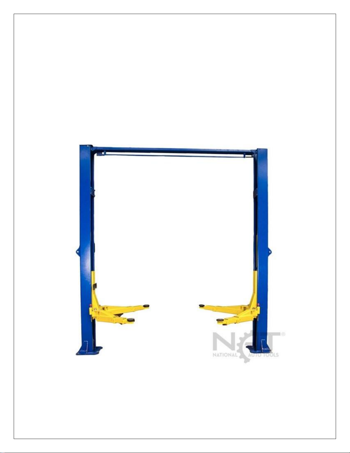
OVERHEAD TWO POST LIFT
FOR MODELS:
NTO-9A - NTO-10A - NTO-9AE
DATE INSTALLED: ____________ SERIAL NUMBER _____________
Page 1 of 20
Page 2

INTRODUCTION
You have purchased a two post 9,000 pound lift that is a great value for the price. Please
read this manual thoroughly before starting any installation. You will find information not
only in install but also safety, maintenance and troubleshooting that should also be
understood.
If properly taken care of, this lift should be useful to you for a long time. Pay attention to
safety and maintenance as they play an important part in making your lift last a long time.
Call us if you have any questions or need any repair parts for this lift.
Thoroughly read this manual before operating the lift. Always display this manual in a
conspicuous location near the lift. Personal injury and property damage incurred due to
non-compliance this these safety instructions are not covered by warranty.
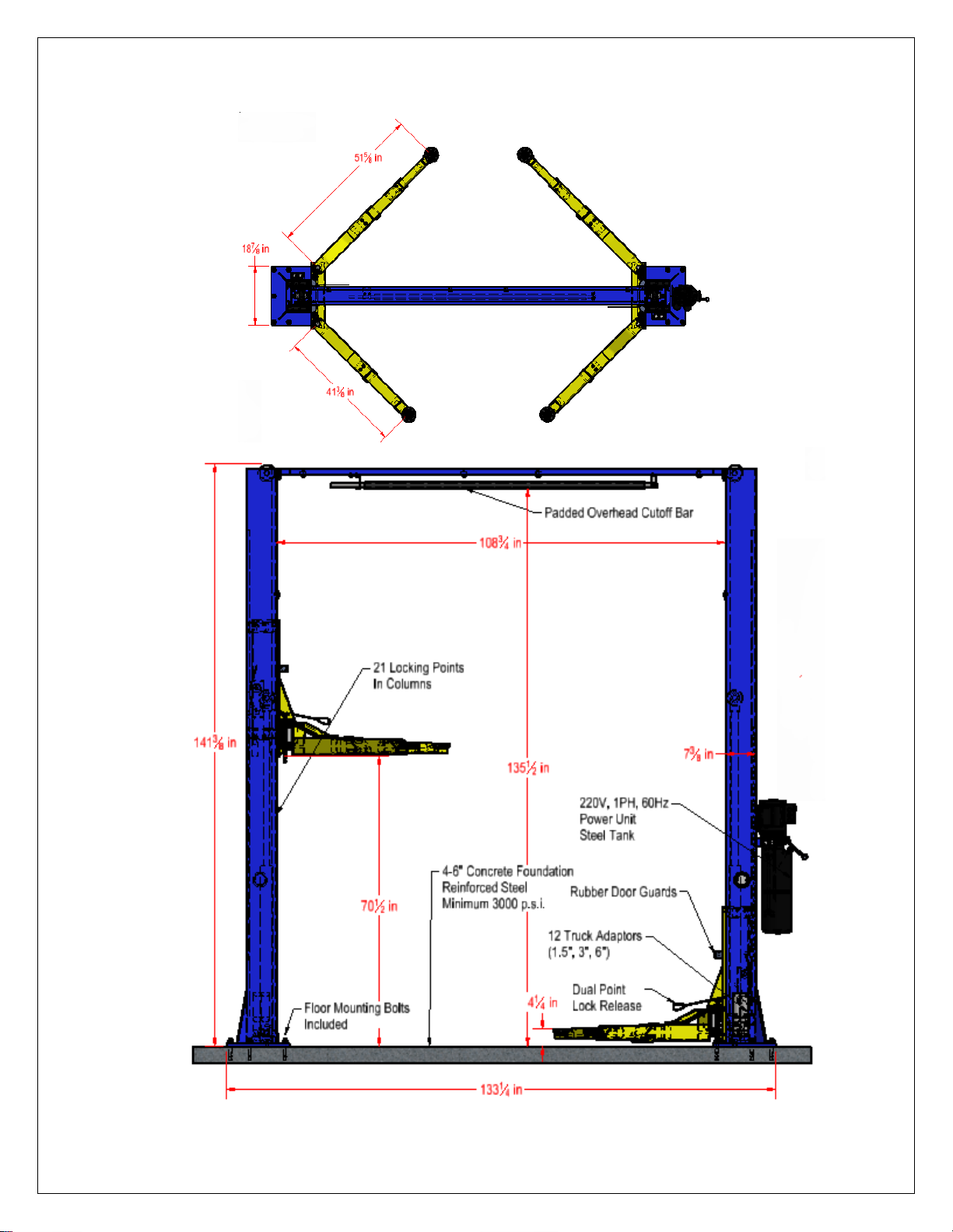
LIFT SPECIFICATIONS
9,000 Pound (NTO-9AE & NTO09A) 10,000 Pound (NTO-10A) Max Capacity
Two Post Overhead Verisymmetric
Triple Arm Length (Max 51.5”, Min 29”)
Double Arm Length (Max 41.5” Min 27”)
Rubber Door Protectors on columns
Chain Lifting – Stronger than cable used on other lifts
Hydraulic Power Unit - 220 V, 1PH, 60Hz (Standard), 3 HP
Lifting Time 40-50 Seconds
Cable Equalization
Locking Method: Dual Point Release
Electric Safety Cutoff Bar
Distance between columns: 109”
Distance to outside of columns: 124”
Drive through width at carriage: 100”
Overall width including power unit: 145”
Height Under Arm at top of Stroke: 73.5”
Height under Arm at top Lock 67”
12 Sets of Drop In Adapters (1.5”, 3”, 6”)
Height to top of pad when lift fully Lowered: 4.5”
Overall Lift Height: 142.5”
Distance outside of base plates: 133”
Shipping Weight: 1407 Pounds
Page 2 of 20
Page 3
Page 3 of 20
Page 4

BOLT BOX CONTENTS
Cable
33’7” Long
7.25” (thread and blank)
4 5/8 Thread
Cable 5/16
½ Stud Threaded
Hole for cable is 5/8 (so can’t use 3/8” Cables)
2 nuts 2 washers
TOOLS TO INSTALL
Hammer Drill
¾” Carbide Drill Bit
Various wrenches, pliers and screwdrivers
Block of Wood
Hammer
Torque Wrench
Tall Ladder
Fork Lift or other method of raising columns and toprails
Electrical connectors to connect 220 volt power unit (use Qualified Electrician)
Level
Chalk Line
Good O-ring Pliers
Grease for column
Chain oil for chains
Vacuum to clean dust from anchor holes
Rags
Allow at least 3-4 hours to set up lift.
SYMBOLS IN THIS MANUAL
Failure to comply with instructions could result in personal injury.
Failure to comply with instructions could result in property damage.
Important Information
Page 4 of 20
Page 5

SHIPPING AND DELIVERY
If not picked up at our location, your freight will be delivered in a semi-truck and box trailer.
Please be sure that a truck this large can access your delivery location. If the truck cannot
gain access, you will have to make other arrangements with the freight company. Your lift
could weigh from 1,200 lbs - 1,900 pounds depending on your model. You will need
assistance, or a forklift, tractor or backhoe, to remove from the delivery truck.
We can arrange for you to pick up at the nearest freight terminal with your personal trailer.
Drivers cannot help you unload the truck. You must unload the lift. Drivers are not required
to come on to your property if they think it is dangerous them, their truck or you property.
Customers are responsible for arranging any delivery appointments with the delivery
trucking company. The driver can only deliver to the address on the delivery receipt (the
driver has no authorization to change delivery address). All products must be delivered to a
physical address. Please note that we do not own or operate the delivery trucks, they are all
common carriers. Customer can arrange an appointment for delivery. Please note that the
driver will not call you when he is at the location or just before arriving. His job is to deliver,
not to call each customer.
Automotive lifts are too large for a lift gate. If you have ordered any product that can be
delivered on a pallet then you can arrange for a lift gate but that will be extra expense.
The following locations are considered to be limited access areas and may require special
equipment or special circumstances for delivery. There is an extra charge to deliver to these
and some other special areas. Customer is responsible for these extra charges..
These areas include but are not limited to:
Residence, any location that has a living residence on site
Farms
Schools
Construction sites
Trade shows
State parks
Government locations with restricted access
Islands
Please note that due to fluctuating fuel costs, any freight costs quoted will only be valid for 3
business days.
Page 5 of 20
Page 6
Our freight carriers assume that when a customer provides a business name, the business
is open from 8AM-5PM Monday-Friday, the business is located at a commercial address,
and that the business does not have a home or any other living residences on the property.
We will not be responsible for redelivery charges to businesses that are not open during the
above mentioned hours when the first delivery attempt was made. Any redelivery or
residential delivery cost that are incurred due to misrepresentation or fault of the customer,
must be paid in full to us or the warranty on the respective product is void. Any storage
charges from the respective freight company must be paid in full before equipment will be
released for delivery. Any costs left unpaid will void the warranty. Customers are responsible
for unloading from delivery truck at time of delivery. Lift gate service cannot and will not be
provided for auto lift delivery.
ANCHORING TIPS
1. Concrete needs to be fully cured and a minimum of 4000 PSI compressive strength.
Thickness 4-6 inches in order to achieve minimum anchor embedment of 3.25”. When
using the standard anchor bolts - if the top of the embedded anchor exceeds 2.25”
above floor grade, you DO NOT have enough embedment.
2. Use the holes in base plates as guide for drilling the ¾” holes needed. Do not drill over
an edge or a seam or a crack. Hole to hole spacing should be a minimum 6.5” in any
direction. Concrete thickness or hole depth should be a minimum of 4”.
CAUTION: DO NOT install on asphalt or other similar unstable surface. Concrete
only. Columns are supported only by anchors in the floor.
3. Using the horseshoe shims provided, shim each column base until each column is
plumb. If one column has to be elevated to match the the other column, full size base
shim plates should be used (not provided).
4. Torque anchors to 120 ft-lbs. Shim thickness MUST NOT exceed ½” when using the
supplied anchors with the lift.
5. If anchors cannot be torqued to 120 ft-lbs. then replace concrete under each column
base with a 4’ x 4’ x 6” thick 3,000 PSI minimum concrete pad keyed under, and flush
with, the top of the existing floor. Let concrete fully cure before installing lifts and
anchors.
6. Anchors must be at least 6” from the edge of the slab or any seam.
7. Use a concrete hammer drill with a ¾” carbide bit. Do not use excessively worn bits or
bits which have been incorrectly sharpened.
8. Keep the drill perpendicular while drilling.
Page 6 of 20
Page 7

9. Let the drill do the work. Do not apply excessive pressure. Lift the drill up and down
occasionally to remove residue to reduce binding.
10. Drill the hole to depth equal to the length of anchor. You can drill completely through the
floor so that when you remove the lift at a later date you can hammer them down instead
of just cutting off with a saw.
11. For better holding power blow dust from the hole.
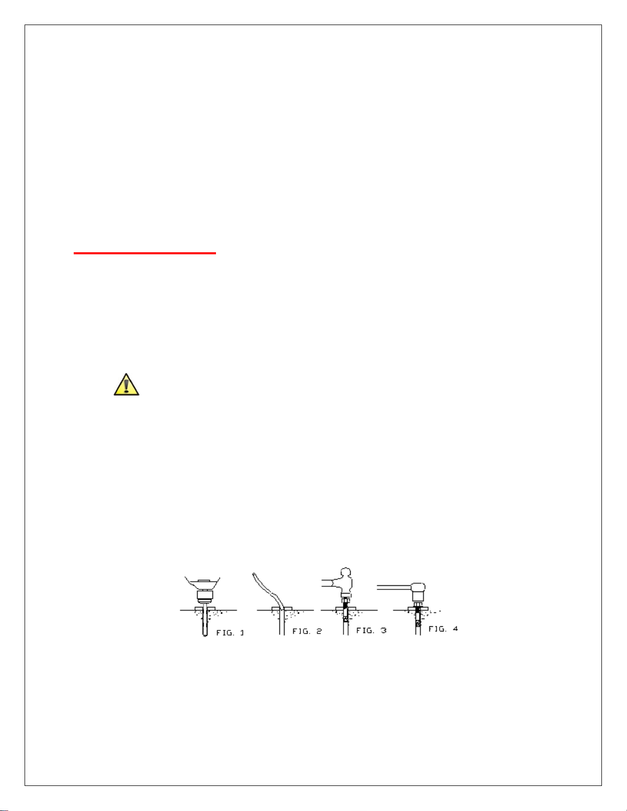
12. Place a flat washer and hex nut over threaded end of anchor, leaving approximately ½
inch of thread exposed. Carefully tap anchor. Do not damage threads. Tap anchor into
the concrete until nut and flat washer are against base plate. Do not use an impact
wrench to tighten. Tighten the nut, two or three turns on average concrete (28 day
minimum cure). If the concrete is very hard only one or two turns may be needed. Check
each anchor bolt with torque wrench set to 120 foot pounds.
13. Recheck Anchors periodically to be sure they have not loosened and retighten as
needed.
INSTALLATION
Check for ceiling clearance first to confirm the lift can be set up in your shop bay. You will
need at least 144” of ceiling height.
CAUTION: DO NOT install on asphalt or other similar unstable surface. Concrete only.
Columns are supported only by anchors in the floor.
1. After unloading the lift, place it near the intended installation location. Remove the
shipping bands and packing materials. Remove the parts from inside that columns.
2. Unbolt columns from packing brackets. You will need a fork lift to remove the columns
due to their weight. Do not discard bolts as they are used in the assembly of the lift.
3. Make sure your choice of installation leaves enough distance from all walls and
obstacles. The ceiling height must be at least 12 feet. It is recommended locate the
power side column on the vehicle driver’s side for ease of operation later.
4. Raise the offside column (not power unit column) to vertical position.
5. Position the columns facing each other at 103.5” inside base plates. Square the columns
by measuring diagonally from corner points on base plates (within ¼”). Or by dropping a
chalk line to help you keep both base plates on the same plane. (Columns must be
parallel to each other).
Page 7 of 20
Page 8

6. Using a ¾” concrete drill, drill the anchor holes in the offside (not power unit) column,
installing anchors as you go. Use a block of wood or rubber mallet to drive anchor bolts
in. drill to a minimum depth of 4” to insure maximum holding power. Drilling through
concrete recommended) will allow the anchors to be driven through the bottom if ever
the anchor needs to be replaced later. Or you decide to move the live at a later date.
(Showing Installation of first Anchor Bolt)
7. Using a level, check column for side to side plumb and from to back plumb. If needed,
use horseshoe shims provided by placing shims under the base plates and around the
anchor bolts. This will prevent bending the column bottom plates (Shim thickness should
not exceed ½”). Tighten anchor bolts to 120 ft-lbs.
8. DO NOT ANCHOR THE POWER UNIT COLUMN AT THIS TIME.
9. Install the overhead cross beam. Be sure to bolt them together by installing the bolts
from inside the cross beam out to avoid interference with the cables when operating the
lift. Bolt the cross beam to the two columns.
10. Assemble cable sheaves on each end of top rail. Flat side of sheaves to the inside to
help when stringing cable later. Assembly consists of O-Rings Plastic spacers, sheaves
and protection shields. Assemble before raising the top rail and bolting to lift.
Page 8 of 20
Page 9

11. After fastening the cross beam, check and confirm that the remaining column is plumb.
(Making sure the power column on left and offside column are plumb. Critical.)
12. Secure the power column, and make plumb. In same fashion as the first column.
13. At this point you can put in all anchors in both columns once you are sure they are
positioned properly and plumb and square. Also make sure you have securely bolted the
top rail. Install the rubber door protectors on both columns with bolts provided.
14. Install the equalizing cables.
a. Manually set both carriages on the first safety latch. Be sure each carriage is at
the same height by measuring from the top of the base to the bottom of the
carriage. DOUBLE CHECK THE LATCHES ARE ENGAGED BEFORE
WORKING UNDER OR AROUND THE CARRIAGES). This dimension should be
within ¼”.
b. Run the first cable. Tighten nut on one cable stud. Pull the other end of the cable
and run nut on it. Tighten both nuts. Repeat above for second cable.
Note: the cable stud that connects to the front right corner of the carriage should be
connected first by pulling the stud through the carriage hold and up where it is easy
to be held by locking pliers. Pull the stud past the locknut. Connect the other ends to
the rear right corners of the carriage with at least ½” of thread showing past the lock
nut (cables run on the inside of the carriage). It may be necessary to manually raise
both carriages above the cylinder to prodi enough space to use the locking pliers.
Make sure the carriage is set in the LOCK position.
Page 9 of 20
Page 10

c. Adjust cables to same tightness. This will allow them to keep the carriages level
as the lift rises.
d. Adjust the carriage cable tension. This is accomplished by tightening the carriage
adjustment nut on top of each carriage. The rear carriage adjustment nut adjust
the opposite post carriage height.
e. The left post carriage nut adjusts the right column carriage, and the right column
carriage nut adjusts the left column carriage. Adjust each cable to approximately
½” side to side play. Check the latch releases to insure the carriage is still
engaged in the appropriate latch.
15. Check cylinders are in place properly. They were installed in factory but may have
moved. Make sure the tip on the bottom of the cylinders fit into the center hole on top of
the cylinder mount in base plate.
16. Pull the pre-attached leaf chain in both sides up and over the chain sheaves on top of
the cylinders if not already done at factory.
17. Mount the power unit on the main side leg to the power unit bracket using the two bolts
and nuts provided.
(Make sure power unit securely attached as it weighs a lot when full of fluid)
Page 10 of 20
Page 11

18. Install all swing arms, make sure that gear rack are engaging the moon gear on the arms
properly. There are two triple and a two double stage arms. The triple arms should be
toward the front of the car as you are sitting in it, two stage arms will hold up the
rear of the vehicle.
19. Truck Adapters – When using lift you can use the three sizes of drop in adapters.
Especially useful on trucks.
(Shown with no adapter, 1.5”, 3”, and 6”)
20. Remove the vent plug from the power unit and fill the reservoir. Use a light weight non
foaming, non-detergent hydraulic oil. The unit will hold 12 quarts. Fill to within two inches
of top. Measure with screw driver or finger.
21. Have a qualified electrician hook up the power unit to the power supply. The electrical
wiring must comply with local code. Protect circuit with time delay fuse or circuit breaker.
22. Installation of Overhead Cut-Off Beam
a. The cut off beam is installed on the top rail and protects against over raising the
lift. There is an electric cut off switch. Remove the wires and thread through the
small tubes on the inside of the power beam. Start from bottom and when you
get to the top reattached to the switch.
Page 11 of 20
Page 12

23. Install hydraulic hoses
a. Connect the hydraulic hoses. Make sure all guides are in place on top of the top
rail for pulling the hoses through.
24. Operate the lift and apply pressure to the safety cut off to insure motor shuts off prioe to
any part of vehicle coming in contact with cut off bar. Adjust as needed.
25. Do not place any vehicle on the lift at this time. Cycle the lift up and down several times
to insure latches engage properly and all air is removed from the system. To lower the
lift, first raise the lift to clear the latches and then pull the two lock release cables and hit
the dump valve to lower the lift to the nearest lock. If latches are out of sync, tighten the
cable on the latch that engages first.
NOTE: Re-Check That All Hardware Has Been Properly Tightened
Page 12 of 20
Page 13

FOR SINGLE POINT RELEASE LIFTS ONLY
(NTO-9A & NTO-10A)
For lifts equipt with a single point lock releae (a leaver that release both sides simultaneously) will require these
additional steps.
1. Route cable up the column, over the release pulleys and back down to the second lock release.
1a. NOTE: Pulleys are attached to the upper outside of each column with supplied hex head bolts.
2. Insert one end of the cable into the hole in the lock lever, leaving 2-3 inches of cable sticking through, then
tighten jam nuts to clamp the cable into place in the lock lever. With the cable attached at the lever end and
routed over both release pulleys, draw the cable under the lock release shaft (as shown) and back up through
the hole in the provided stud. Secure cable end with jam nuts (same as lever side) and trim excess cable.
Page 13 of 20
Page 14

MAINTENANCE
The following is the suggested maintenance schedule for this lift. If you hear or see any sign of
impending failure, cease operation immediately and inspect, correct and replace failed or
failing parts.
USERS SHOULD ALWAYS INSPECT LIFTING EQUIPMENT AT THE START OF EVERY
SHIFT. THESE AND OTHER PERIODIC INSPECTIONS ARE THE RESPONSIBILITY OF THE
USER/OWNER.
NOTE: Relocating or changing components may cause problems. Each component in the
system must be compatible; an undersized or restricted line will cause a drop in pressure. All
valve, pump, and hose connections should be sealed and/or capped until just prior to use. Air
hoses can be used to clean fittings and other components. However, the air supply must be
filtered and dry to prevent contamination. Most important - cleanliness - contamination is the
most frequent cause of malfunction or failure of hydraulic equipment.
a. DAILY PRE-OPERATION CHECK
ATTENTION! LOOK OUT! Daily check of safety latch system is very important- the
discovery of device failure before needed could save you from expensive property
damage, lost production time, serious personal injury or even death.
i. Check safety lock audibly and visually while in operation. Check safety latches
for free movement and full engagement with rack.
ii. Check hydraulic connections, and hoses for leakage.
iii. Check chain and cable connection for bends, cracks and looseness.
iv. Check for frayed cables in both raised and lowered positions.
v. Check snap rings on all rollers and sheaves.
vi. Check bolts, nuts, and screws and tighten as needed.
vii. Check wiring & switches for damage.
viii. Clean any dirt, grease or any other corrosive substances from base plates.
ix. Check floor for stress cracks near anchor bolts.
x. Check swing arm restraints.
b. WEEKLY MAINTENANCE
i. Check anchor bolts torque to 120 ft-lbs.
ii. Check floor for stress cracks near anchor bolts
iii. Check hydraulic oil level and if low find leak you may have to replace or repair
cylinder or power unit.
iv. Check and tighten bolts and nuts, and screws.
v. Check cylinders for free movement. Look out for excessive ware on cylinder
yokes or pulley pins.
vi. Check cable pulleys for free movement and excessive ware.
c. YEARLY MAINTENANCE
i. Lubricate chain
ii. Grease rub blocks and column where they rub
iii. Change hydraulic fluid. Good maintenance procedure makes it mandatory to
keep hydraulic fluid clean. No hard fast rules can be established;, operating
temperature, type of service, contamination levels, filtration, and chemical
composition of fluid should be considered. If operating in dusty environment
shorter intervals may be needed.
Page 14 of 20
Page 15

d. The following items should only be performed by trained maintenance expert
i. Replace hydraulic hoses.
ii. Replace chains and rollers.
iii. Replace cables and sheaves.
iv. Replace or rebuild air and hydraulic cylinders.
v. Replace or rebuild power units
vi. Check hydraulic cylinder rod and rod ends for deformation or damage.
vii. Check cylinder mount for looseness or damage.
OPERATION
1. Each support arm is provided with an automatic arm restraint which unlatches
automatically when the lift is fully lowered. When the carriages are in the raised
position, the arm restraint can be disengaged by pulling the two release cables.
2. Fully lower the lift and swing the arms to full drive through position.
3. Slowly position vehicle midway between adapters. Apply the parking brake
4. Swing the adjust the telescope arms as required to position adapters under vehicle
manufacturer's recommended lifting points for the vehicle you are working on.
5. Turn the disk adapters so they evenly contact all four lifting points. Add the 1.5”, 3”,
or 6” truck adapter extensions as needed to fully contact the lifting points.
6. Make sure lifting points are free of grease or oil as this might make the adapters slip
off the lifting point when vehicle is raised. VERY IMPORTANT!
7. Do not place any vehicle on the lift at this time. Cycle lift up and down several times
to insure latches click together and all air is removed from the system. To lower the
lift, latch releases must be manually released. Latches will automatically reset once
the lift ascends approximately 20” from base.
8. If latches click out of synchronization, tighten the cable on the one that clicks first.
9. Once the disk adaptors contact the lifting points check arm restraints for
engagement. If necessary, slightly move arms until the gear segments mesh.
10. Never unlatch the arm restraints when the lift is under load.
11. Do not stand under lift when lift is moving and before locks are engaged..
12. Always lift the vehicle using all four adapters.
RAISING VEHICLE
1. During raising and lowering cycle closely watch the vehicle and the lift, do not allow
anyone to stay in lift area and make sure the vehicle doors are closed.
2. Once the disk adapters contact the lift points, check arm restraints for engagement.
After raising the vehicle briefly, stop and check adapters for secure contact.
3. Press button on power unit to begin raising the lift. It may take about 40 to 50
seconds if raising to full height. Remember there are many other stopping points in
between should you not want to raise to full height.
4. Lift stops once button is released or upward travel limit is reached.
5. Observe all accident prevention regulations.
6. Do not allow unauthorized persons to stay under the raised vehicle.
7. Avoid rocking of vehicle. Use stabilizer stands (not provided) to stabilize long
vehicles for extra safety.
8. Fasten the vehicle to the support arms using lashing straps when removing or
installing heavy components. This will keep vehicle for shifting and possibly falling so
very important.
Page 15 of 20
Page 16

LOCKING
1. The latch mechanism will 'trip over' when the lift raises and drop into each latch stop. But, to
lock the lift you must press the lowering lever to relieve the hydraulic pressure and let the
latch set tight in the nearest lock position.
2. Always lock the lift before going under the vehicle. Never allow anyone to go under the lift
when raising or lowering.
3. Read the safety procedures in the manual.
LOWERING VEHICLE
1. Note: It is normal for an empty lift to lower slowly. It may be necessary to add weight.
2. Raise the lift until the latch clears.
3. Pull both latch releases
4. Warning: Always release both sides.
5. Press and hold the lowering lever at the power unit to lower the lift.
SAFETY
1. The lift is designed for the safe lifting of automotive vehicles within the lifting capacity of the
lift. Observe the rated load capacity and load distribution of the lift.
NTO-9AE Max Load 9,000lbs
NTO-9A Max Load 9,000lbs
NTO-10A Max Load 10,000lbs
2. In principle, the lift is designed for both approach directions. For long service life, use the
short (Two Section) support arms for engaging the engine side of the vehicle.
3. The lift should be installed by professional lift installers. If you do it yourself be careful on
ladders and using heavy equipment like forklifts. Do not install near explosive or flammable
liquids, outdoors or in moist rooms (e.g. car wash) or where rain can reach the power unit. It
is not rated for use in wet conditions. If you do set it up outside you must keep all water from
reaching the power unit. This is not just for safety but also will ruin the power unit and that is
not covered under warranty.
4. SAFETY TIPS FOR OPERATION
a. Read and understand this manual before install or using the lift.
Page 16 of 20
Page 17

b. Lift should only be operated by fully trained personnel.
c. Keep the lift and lift area clean and free of tools, parts, debris, etc.
d. Once the disk adaptors contact the lift points, check arm restraint mechanisms on
each arm for engagement.
e. When you start raise the vehicle a little and then check the disk adapters have
secure contact with vehicle lifting points. Always lift the vehicle using all four
adapters.
f. Close vehicle doors are closed during raising and lowering cycles.
g. Closely watch the vehicle and the lift during raising and lowering cycles. Do not allow
anyone to stay in lift area during raising and lowering cycles.
h. Never allow anyone on lift or inside when raising or lowering the lift.
i. Only use the lift for its intended purpose.
j. Comply with the applicable accident prevention regulations of your area.
k. Do not overload the lift. The rated load capacity is indicated on the lift nameplate.
l. Only use the vehicle manufacturer’s recommenced lift points
m. After positioning the vehicle on the lift apply the parking brake.
n. Use caution when removing or installing heavy components (center-of-gravity
displacement). And be careful when picking up trucks with heavy equipment in
the bed as this will change the center of gravity of the truck and could lead to
accident. This is very important.
o. Protect all parts of the electrical equipment from humidity and moisture.
i. You must hold the controls in the engaged position to raise or lower the lift.
p. Equalizing System
i. The lift has equalizing cables to ensure level movement of both carriages.
Make sure they are adjusted properly.
q. Collision Prevention Switch
i. A cut off is provided to prevent collision between vehicle roof and cross
member. Test frequently to be sure it is fully operational.
r. Pinch Point Protection
i. During lowering cycles the support arms automatically stop at a height of 4.5
inches from ground.
ii. To lower the lift completely, raise lift off the lock, and hold the dump handle to
lower. Lift travel to the lower limit stops is accompanied by an audible click.
iii. Automatic Arm Restraint = Once the lift is raised, the arm restraints are
locked automatically to avoid any swivel under load. Make sure the locking
gears engage when lifting a load for safety.
5. SAFETY TIPS FOR SERVICING LIFT
a. Maintenance or repair work by trained service personnel only.
b. Turn off the electricity to lift before doing any maintenance or repair work. Any
electrical work on the lift should only be done by certified electricians. This is
especially critical when initially installing the power unit because errors here, if
not done by qualified electricians, will not be covered under warranty.
c. Ensure that ecologically harmful oils are disposed of only in accordance with the
appropriate regulations.
d. Do not use high pressure/steam jet cleaners or caustic cleaning agents on the lift.
Risk of Damage.
e. Do not replace or override the safety devices
Page 17 of 20
Page 18

f.
PROBLEM
POSIBLE CAUSES
SOLUTIONS
Motor Not Running
Breaker or fuse blown
Call Electrician
Motor thermal overload tripped
Wait for overload to cool
Faulty wiring connections
Call electrician
Defective button
Call electrician for checking
Motor runs but lift does
not rise
A piece of trash is under check
valve
Push handle down and push the up
button at the same time. Hold for
10-15 seconds. This should flush
the system.
The clearance between the
plunger valve of the lowering
handle is too small
Check the clearance between the
plunger valve of the lowering
handle. There should be 1/16”
Remove the check valve cover and
clean ball and seat
Oil level should be just under the
vent cap port when the lift is down
Oil Blows out breather
of power unit
Remove excessive weight from lift.
Oil reservoir overfilled
Reduce the oil to the oil level
Motor hums and does
not run
Take off and straighten
Faulty wiring
Call electrician
Bad capacitor
Call electrician
Low voltage
Call electrician
Remove excessive weight from lift
Lift Jerks going up and
down
Air in hydraulic system
Rails lift all the way to the top and
return to the floor. Repeat 4-6
times. Do not let this overheat
power unit.
Oil Leaks
Oil Leaks around the tankmounting flange. Oil reservoir
overfilled
Check the oil level to the tank. The
level should be two inches below
the flange of the tank. Check with a
screwdriver
Oil leaks around the rod end of
the cylinder. The rod seal of
the cylinder is out
Rebuild or replace the cylinder
Oil leaks around the breather
end of the cylinder. The piston
seal of the cylinder is out.
Rebuild or replace the cylinder
Lift makes excessive
noise
Leg of the lift is dry and
requires grease.
Grease the legs
Grease the pulley assembly.
Replace the pins or cylinder yoke.
TROUBLESHOOTING
Dirty on the ball and seat of
check valve
Oil level too low
Lift lowered too quickly while
under a heavy load
Impeller fan cover is dented
Lift Overloaded
Cylinder pulley assembly or
cable pulley assembly is not
moving freely
May have excessive wear on
pins or cylinder yoke
Page 18 of 20
Page 19

PURCHASE TERMS AND WARRANTY
DAMAGE/MISSING PARTS POLICIES:
All parts you find defective must be returned for inspection before a replacement is shipped. All
parts will be inspected and if found to be defective a replacement and/or repair to parts will be
sent. If no defect is found, customer is responsible for all shipping costs of all parts. The
shipping costs must be paid by customer prior to any parts being sent back to customer. Auto
Lift Motors are for use indoors and will not be warranted if installed outside.
All shop equipment must be inspected upon receipt. Make note of any visible damage or
missing pieces on the bill of lading. We will not be liable for damages occurred by the freight
company if not noted on the bill of lading. Missing power units and/or motors must be reported
at time of delivery. Any missing parts or incorrect equipment needs to be reported within three
days of receipt. Anything reported after three days of receipt will be replaced or returned to us at
the customer’s expense.
PAYMENT POLICIES:
We accept all major credit cards, money orders, cashiers checks and wires. If paying by
personal or business check please allow 7 business days for check to clear. All checks must
clear bank before we ship an order. Payment must be received before product will ship. We do
not ship COD. Deposits for custom orders are non-refundable. If payment is tendered by credit
card or check by phone, purchaser/customer agrees to instruct their credit card or banking
institution honor payment. Purchaser/Customer further agrees to not initiate a credit card
charge back and/or cancel check payment by phone at any time once automotive equipment
has shipped. Purchaser/Customer agrees that all sales are final once product has shipped.
RETURN POLICIES:
ALL SALES ARE FINAL ONCE YOUR AUTO EQUIPMENT HAS SHIPPED. Orders canceled
after payment is processed but before shipment, will be charged a 15% cancellation fee of the
total invoice. If a product is shipped and purchaser/customer refuses product then
customer/purchaser will be responsible for shipping costs both ways and a 30% restock fee. We
do not accept returns of used equipment. All equipment must be in original undamaged
packaging. Pictures on site are for display purposes only and may not represent exact design of
equipment. Customer is responsible for all charges associated with returning equipment,
including but no limited to fork lift or loading equipment needed to put product on freight truck,
costs associated with returning equipment to authorized freight terminal, packaging equipment
in a manner sufficient for shipping on freight truck. There is no compensation for cost of time or
packaging materials needed to return product.
WARRANTY POLICIES:
There is no labor warranty on any products.
The supplier is not responsible for any problems or damage that occurs from the installation of
the power unit and/or motor by anyone who is not a certified electrician. It is required by law that
we cannot provide an electrical wiring diagram. The supplier is not responsible for any cost that
may arise from the certified electrician or any repair costs caused by improper installation of
Page 19 of 20
Page 20

power units and/or motors. If any disputes arise, the supplier requires a copy of the invoice from
the certified electrician with an itemized report of the work done.
The lift is warranted by our supplier for one year. Auto Lifts carry a 2 year structural warranty if
installed indoors. Warranty is for parts only. No labor warranty exists. Hydraulics and Electronics
are covered under 1 year parts replacement. Warranty does not cover rubber lifting pads on two
post lifts. Replacement parts or replacement equipment being sent to the customer does not
represent an extension or renewal of the warranty period. Shipping of warranted parts is for
normal ground shipping only within the USA.
NOTE: All Shipping costs are paid by customer after first 60 days of warranty period, no
exceptions.
No warranties exist for any incidental cost occurring from loss of use of product. Warranty is not
transferable. Warranty is issued to original purchaser only and cannot be transferred to anyone
else.
Any attempts at charge backs or legal action will void the warranty on the product purchased
regardless of the decisions made by all companies involved in the transaction and or the
decision of the courts. Once warranty is voided, it cannot be reinstated. No other warranty is
expressed or implied. Warranty is governed by the laws of the State of Texas, County of
Tarrant. Our supplier will not enter into any verbal agreements regarding changes to the stated
warranty policy. We reserve the right to change or amend any measurements, instructions,
policies, pictures, and warranties, as stated in our manuals, on our website, and on any other
printed or published materials, without notice to customers prior to changes being made.
Any and all vehicles pictured with our products do not imply a set measurement or dimension in
regards to the lift with which they are pictured. Purchaser/Customer has read and understands
the whole of this document and all parts thereof. Purchaser/Customer further understands that
this document and all parts thereof is governed in whole or in part by the law of the State of
Texas. Any action at law, suit in equity, or other judicial proceedings for the enforcement of this
document or any provision thereof shall be instituted only in the courts of the State of Texas,
County of Tarrant. The covenants and conditions contained in this document shall apply to and
bind the parties, purchasers, customers, heirs, legal representatives and assigns of the parties.
ISO 9001 AND CE CERTIFICATION
This lift is built in a factory that carries an ISO-9001 Quality Certification. This is an
internationally accepted quality control standard. ISO-9001 is overseen by an independent third
party with no vested interest in the company seeking certifications. The power unit carries the
CE mark which is a mandatory safety mark and ensures that your products are tested and safe.
Page 20 of 20
 Loading...