

Page 1
TM
92-0660 Rev. 080423
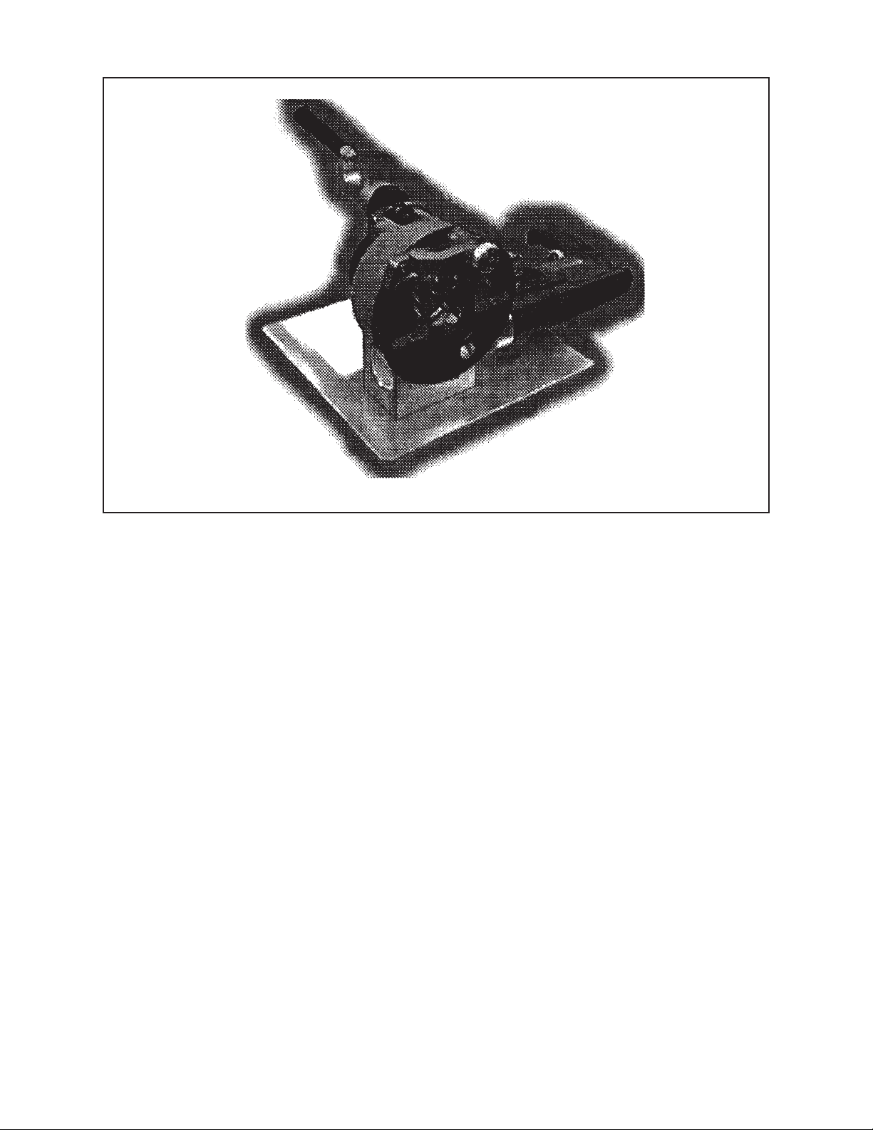
Model 572AC SEVERMASTER
TABLE OF CONTENTS
CUSTOMER MESSAGE Inside Front Cover
SAFETY PRECAUTIONS 3
GENERAL DESCRIPTION 6
SPECIFICATIONS 7
MAINTENANCE 9
OPERATION 11
INSTALLATION 14
CUTTING SPEEDS AND FEEDS 16
COLLETS 18
TOOL BITS 20
TROUBLE SHOOTING 21
ILLUSTRATED PARTS BREAKDOWN 23
TOOL BIT RESHARPENING POLICY Inside Back Cover
WARRANTY INFORMATION Inside Back Cover
Page 2

Copyright 2008
Proprietary property of TRI TOOL Inc.
No reproduction, use, or duplication of the information
shown hereon is permitted without the express written
consent of TRI TOOL Inc.
Page 3
SAFETY PRECAUTIONS
IN GENERAL
When using rotating head cutting equipment, basic safety precautions should always
be followed to reduce the risk of personal injury.
Operate this tool only in accordance with specific operating instructions.
Do not override the deadman switch on the power unit. Locking down, ob-
WARNING:
DRESS CONSIDERATIONS
structing, or in any way defeating the deadman switch on the power drive unit
may result in serious injury.
Model 572AC SEVERMASTER
TM
Use standard safety equipment. Hard hats, safety shoes, safety harnesses, protective clothes, and other safety devices should always be used when appropriate.
Use safety glasses. Do not operate cutting tools without eye protection.
Dress properly. Do not wear loose clothing or jewelry. They can be caught in rotating and moving parts. Avoid slippery floors or wear nonskid footwear. If you have
long hair, wear protective hair covering to contain it.
WORK AREA
Keep the work area clean. Cluttered work areas and benches invite injuries.
Consider the work area environment. Keep the area well lit. Keep electrical cords,
cables, rags, rigging straps, and etc. clear of rotating equipment. Do not use powercutting tools in the presence of flammable liquids and gasses.
Keep visitors away. Do not let visitors or untrained personnel at or near operating
tools. Enforce eye protection requirements for all observers.
Do not over reach. Keep proper footing at all times.
Stay alert. Watch what you are doing. Use common sense. Do not operate tools
when you are tired.
92-0660 : Rev. 080423
3
Page 4

TRI TOOL INC.
TOOL CARE
Maintain tools with care. Keep tools in good operating condition. Sharp tool bits
perform better and safer than dull tool bits. Well maintained tools function properly
when needed.
Check for damaged parts. If a tool has malfunctioned, been dropped or hit, it must
be checked for damage. Run no-load tests and feed function checks. Do a complete visual inspection.
Electric motors. Use only with proper AC voltage power sources and observe all
normal electric shock hazard procedures.
Do not abuse power and control cords. Pulling or running over cords and cables
can result in electrical shock hazards and malfunctions. Keep control and power
cords out of all cutting fluids and water.
Hydraulic drives. Observe proper procedures for electrically driven power sources.
Avoid damage to hydraulic lines. Keep quick-disconnects clean. Grit contamination
causes malfunctions.
Air tools. Check the exhaust muffler. Broken or damaged mufflers can restrict air
flow or cause excessive noise. Use air motors only with a filtered, lubricated and
regulated air supply. Dirty air, low-pressure air or over pressure air will cause malfunctions, including delayed starting.
AREA EQUIPMENT
Secure work. Whenever possible use clamps, vises, chains and straps to secure
pipe.
Make sure the tool is secured; it is safer to have both hands free to operate the tool.
TOOL USE
Use the right tool and tool bit for the job. Do not use a tool, which is incorrect for the
job you are doing.
Keep the tool bits fully engaged in the tool bit holders. Loose bits are a safety hazard.
4
92-0660 : Rev. 080423
Page 5

Model 572AC SEVERMASTER
Disconnect power supply during setup and maintenance. Use all ‘Stop’ or Shut off’
features available when changing or adjusting tool bits, maintaining the tool, or when
the tool is not in use.
Remove adjusting keys and wrenches before applying power to the equipment.
Develop a habit of checking the tool before turning it on to make sure that all keys
and wrenches have been removed.
Do not force tools. Tools and tool bits function better and safer when used at the
feed and speed rate for which they were designed.
Do not reach into rotating equipment. Do not reach into the rotating head stock to
clear chips, to make adjustments, or to check surface finish. A machine designed to
cut steel will not stop for a hand or an arm.
Handle chips with care. Chips have very sharp edges and are hot. Do not try to pull
chips apart with your hands; they are very tough.
TM
Avoid unintentional starts. Do not carry or handle tools with your hand on the operating switches or levers. Do not lay the tool down in a manner that will start the
drive. Do not allow the tool to flip around or move when adjusting or changing tool
bits.
Store idle tools properly. Disconnect tools from the power source and store in a safe
place. Remove tool bits for safe handling of the tool.
92-0660 : Rev. 080423
5
Page 6

TRI TOOL INC.
GENERAL DESCRIPTION
The Model 572AC SEVERMASTERTM severs 1/4” to 2” (6.35 mm to 50.80 mm)
diameter tubes and thin wall pipe within the size range.
This machine enhances productivity by incorporation of an Auto-Cycle Tool Module
and Quick Lock Collet Closure.
The Auto-Cycle Tool Module incorporates a cam cycle tool bit feed mechanism,
which automatically returns the tool bit to the home position ready to start the next
cut.
The tool module also allows setting the start and finish cut position to minimize the
cycle time.
The feed increment per revolution is adjustable to match the cutting relative to the
material.
A variable speed motor provides cutting speed control for tool bit life and ID burr
condition.
The Quick Lock Collet Closure mechanism actuates the Collet with a single lever
stroke and provides for simple Collet changes.
Tool bit options are available to minimize the burr on either of the mounting side or
the drop-off side of the sever line and in different edge widths to match the tube wall
thicknesses.
The Model 572AC also incorporates mounting features to allow use of an SQM-1AC
Tube Squaring Module for optimum burr free ends.
Model 572AC SEVERMASTERTM System, consists of the mainframe with the Quick
Lock Collet Closure, Auto-Cycle Tool Module with adjustable depth of feed from
.001” to .005” (.02 mm to .13 mm) per revolution, drive motor, wrench kit, operator's
manual and carrying case.
6
92-0660 : Rev. 080423
Page 7
SPECIFICATIONS
MACHINE FEATURES
Pneumatic drive system: Available on request.
Electric drive: 115 vac, 28 to 60 hz, 5.25 amp
230 vac, 50/60 hz
Maximum cutting head free speed: (Electric) Low: 60 rpm, High: 120 rpm
Mounting: Manually actuated Collet clamping system.
Feed: Autofeed system adjustable from .001” to .005” (.02 mm to .13 mm).
Model 572AC SEVERMASTER
TM
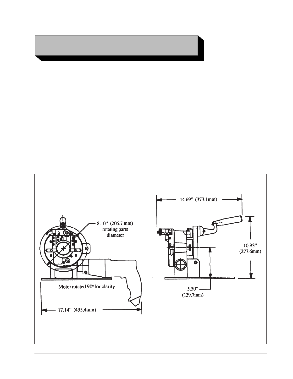
Weight: 29 lbs. (13 kg)
Envelope, Model 572AC SEVERMASTER
TM
92-0660 : Rev. 080423
7
Page 8

TRI TOOL INC.
DESIGN AND OPERATING FEATURES
The Model 572AC accepts its own torque through the Collet clamping system.
The Collet provides accurate centering and full diameter support for minimum
distortion of thin wall tubing.
Gear driven powerhead rotates on a precision cross roller bearing.
Single lever actuation of Collet.
Gears are enclosed for operator safety.
The wrenches that are required for operation of the machine are supplied.
CUTTING CAPACITIES
1/8” pipe through 1 1/2” pipe schedule 5
1/4” through 2” (6.35 mm through 50.80 mm) diameter tubing up to .065” (1.65 mm)
wall.
MATERIAL CUTTING CAPABILITES
Mild steels, chrome steels (Rc 35 max.), stainless steel, copper-nickel and aluminum
without limitations other than size and wall thickness as specified.
Inconel and some other high-temperature alloys may require special procedures as
a function of wall thickness.
Contact TRI TOOL Inc.’s Engineering Department for details.
8
92-0660 : Rev. 080423
Page 9

IN GENERAL
All components should be cleaned and coated with a light film of oil prior to use.
Use a clean, non-detergent oil, preferably SAE 10 (90 SSU) or lighter.
The air supply for the Model 572AC (pneumatic drive) should include an adequate
filter, regulator and lubricator (FRL).
The air supply for the Model 572AC is operated in such a manner that the tool
holder collects debris while cutting, the tool holder and the slides should be cleaned
after each cutting operation.
MAINTENANCE
Model 572AC SEVERMASTER
TM
Tool life may be severely shortened, unless chips and/or other debris that have been
deposited on the cutting head during the machining operation are removed.
RECOMMENDED MAINTENANCE SHCEDULE
Daily maintenance when the unit is in operation includes wiping the unit down and
spraying with rust preventative under severe humidity conditions. Visually inspect for
loose screws, missing screws, damage, etc.
After every 20 hours of actual operation, lubricate the male and female tool holder
slides.
After every 40 hours of actual operation, thoroughly clean and lubricate main gear,
drive gear, male and female tool slides, and tripper bracket assembly.
If the Model 572AC is to be stored or if it will remain out of service for a significant
period of time (30 days or more), it should be thoroughly cleaned lubricated and
sprayed with a rust preventative prior to storage.
TOOL HOLDER MAINTENANCE
Clean the slide rails, the tool holder, and the feed components.
Inspect these parts for damage and replace as required.
Lubricate and reassemble.
92-0660 : Rev. 080423
9
Page 10

TRI TOOL INC.
Adjust the adjustable slide rail to provide a firm, but not excessive pressure on the
tool holder.
The slide rails must be over tightened to squeeze the oil into a thin film against the
male and female surfaces of the slide rails.
Reset for proper operation.
TRIPPER BRACKET ASSEMBLY LUBRICATION AND ADJUSTMENT
Back off the half-dog set screw until it disengages from the tripper shaft.
Remove the tripper shaft assembly from the bracket and clean off all of the old
lubrication.
Apply fresh lubrication to the tripper shaft assembly and reinstall it in the bracket.
Screw in the half-dog set screw until it locates itself in the slot on the tripper shaft.
Try turning the tripper shaft assembly to ensure that the set screw is in the slot of the
tripper shaft assembly and is preventing it from rotating.
LUBRICANT RECOMMENDATIONS
The drive gears require a heavy duty grease such as “Chevron Ultra Duty Grease,
ER, NLGI2”.
The slide rails and tool holder require a light oil such as SAE 10 light machine oil.
The tripper bracket assembly also requires a SAE 10 light machine oil for normal
conditions and under dusty conditions a silicone, graphite or molybdenum disulfide
‘dry’ lubricant.
A light film of all-purpose grease may be used, but it must be used, but it must be
checked for grit contamination frequently.
10
92-0660 : Rev. 080423
Page 11
OPERATION
PRELIMINARY
Read the operating instruction carefully before attempting to operate the Model
572AC SEVERMASTERTM.
INSERTING THE COLLET
Select the desired size Collet for the pipe or tube to be worked on.
Raise the handle to release pressure on the check nut.
Rotate the check nut until the eyebolt can be raised out of the slot and then the
hinge bracket may be rotated back and down.
Model 572AC SEVERMASTER
TM
Remove the pusher sleeve from the main housing.
Remove the Collet, if there is one, from the inside of the main housing.
Wipe the internal contact surface clean before inserting another Collet into the main
housing.
Insert the correct Collet into the main housing and then slide the pusher sleeve back
into the main housing and into contact with the Collet.
92-0660 : Rev. 080423
11
Page 12
TRI TOOL INC.
Rotate the hinge bracket back up and let the eyebolt drop back into the slot.
Rotate the check nut on the eyebolt to secure in the slot.
MACHINING INSTRUCTIONS
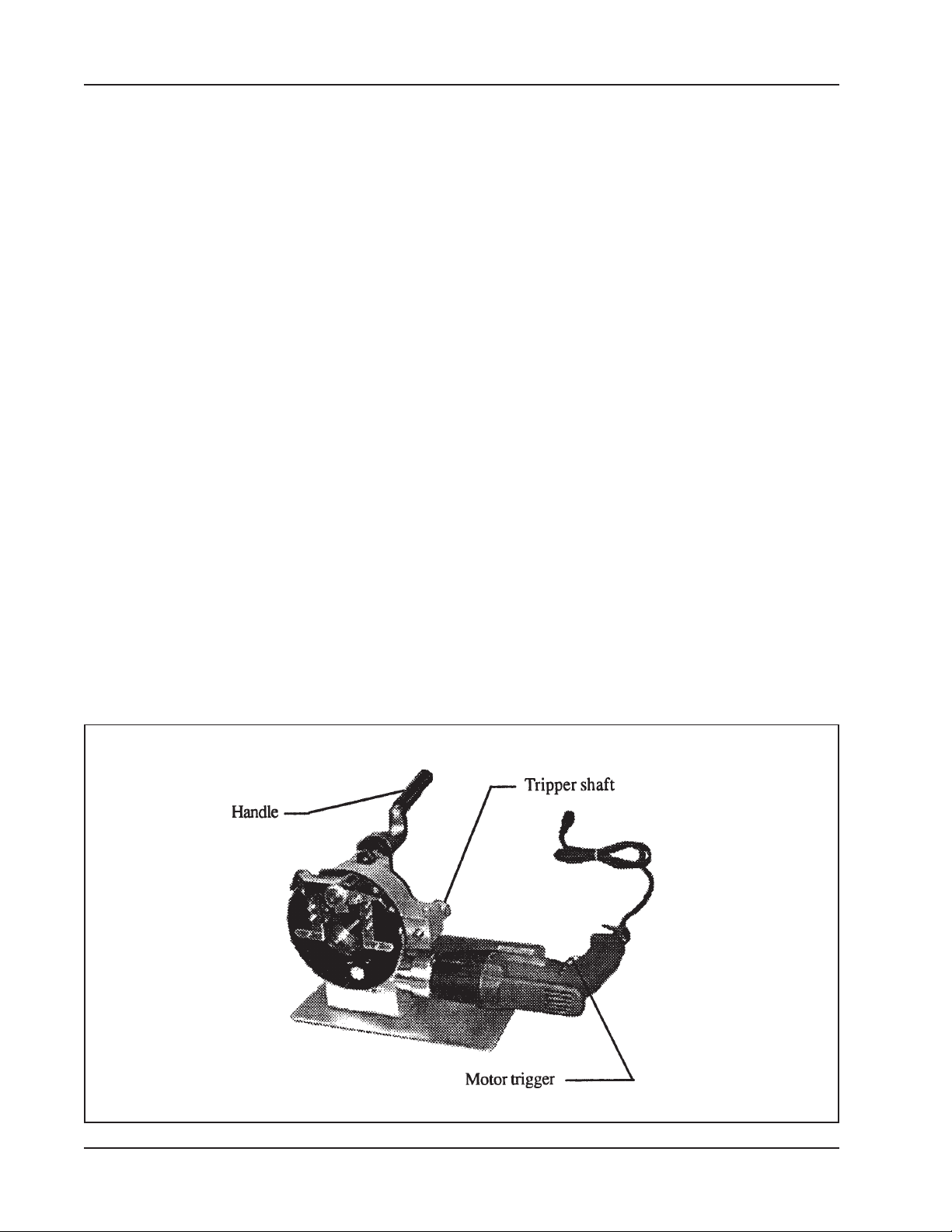
Turn the motor on to full speed by depressing the lever.
The motor should be at the low speed setting to 1.00” to 2.00” (25.4 mm to 50.8 mm)
diameter tube or at the high speed setting for .25” to 1.00” (6.4 mm to 25.4 mm)
tube.
Engage the feed by pushing the tripper shaft in.
Monitor the cutting operation and apply cutting fluid as necessary.
The machine operation is finished when the tool holder returns home, release the
lever in order to turn off the motor.
Loosen the Collet by rotating the handle up.
Remove the pipe or tubing from the Model 572AC.
The tool holder will retract automatically in 5 to 10 revolutions.
There is an audible ‘snap’ when the tool holder returns to the home position.
12
92-0660 : Rev. 080423
Page 13

Model 572AC SEVERMASTER
Observe the relationship between the pipe or tube and the tool bit.
TM
NOTE:
NOTE:
The tool holder may be reset quickly by hand by rotating the cam feed knob
to pick up the feed slack.
It is not necessary to disengage the tripper shaft after each cutting operation.
92-0660 : Rev. 080423
13
Page 14
TRI TOOL INC.
INSTALLATION
WARNING:
Install a Collet into the Model 572AC.
Insert a tube into the Collet and bring it flush to the front of the Collet and clamp the
tube in place.
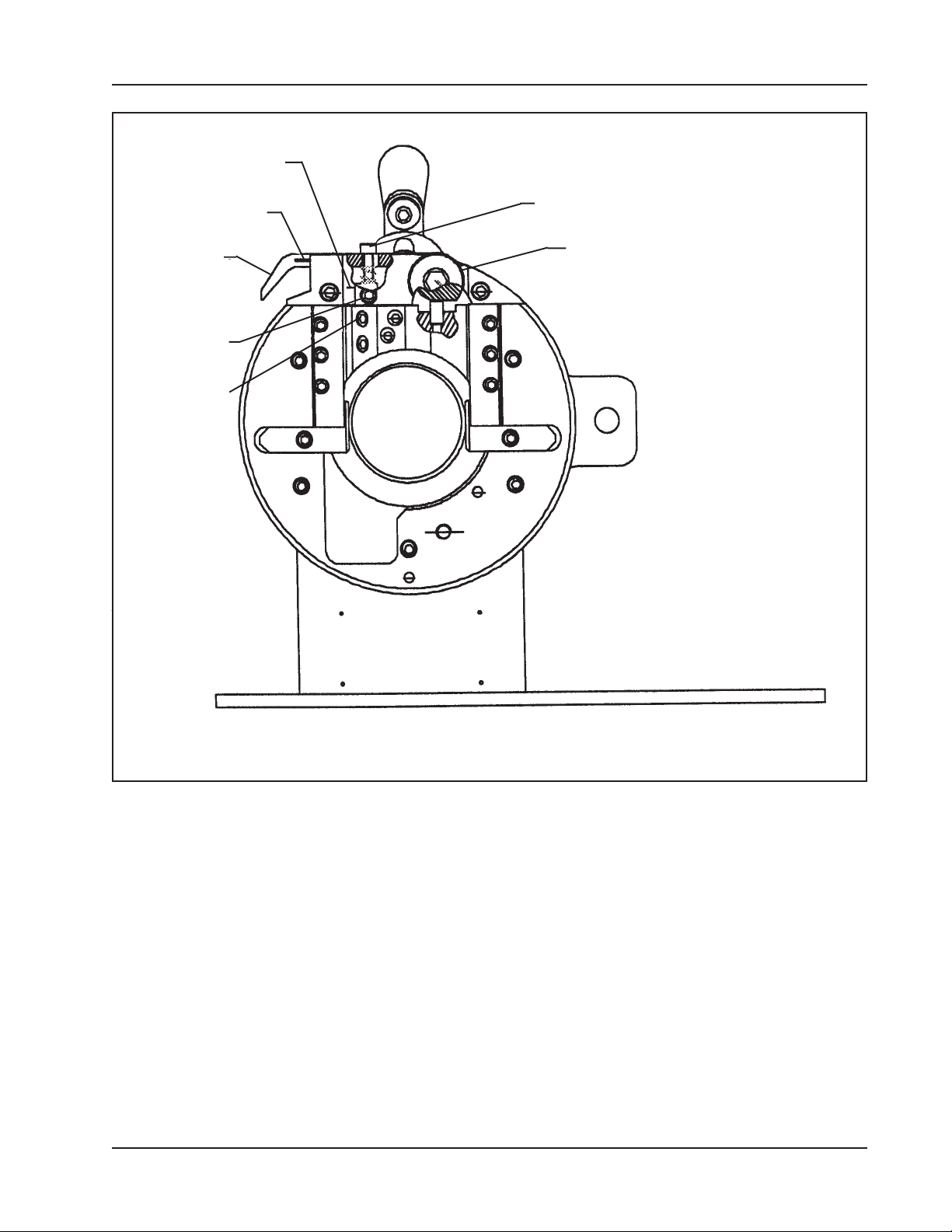
Rotate the cam feed knob counter-clockwise with a 3/8” wrench, so that the scribe
mark points to the bottom (this will place the tool holder to the end of the feed).
NOTE:
Slide a tool bit into the tool slot until the end of the cutting edge of the tool bit passes
the ID of the tube by approximately .020”.
CAUTION:
Secure the tool bit in place by tightening the (4) four set screws in the tool holder.
Make sure that the Model 572AC is disconnected from its power source
before installing a tool bit.
The cam can only rotate in the direction noted on the knob with an arrow.
DO NOT install the tool bit backwards; it will not cut and may destroy the
tool bit.
Rotate the cam feed knob until the tool holder returns to top of its travel.
Screw in the feed limit adjustment screw until the end of the cutting edge of the tool
bit just clears the OD of the tube.
Rotate the cam feed knob counter-clockwise to pick up the feed slack.
Loosen the Collet and re-position the tube to sever.
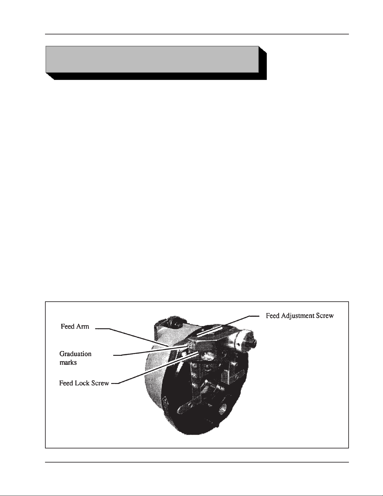
To adjust the feed rate, loosen feed lock screw, rotate the feed adjustment screw
and read the feed rate graduations to find the desired feed rate.
Some experimentation should be made to maximize the efficiency and tool bit life.
A feed rate of .002” to .003” (.05 mm to .08 mm) will accommodate most tube
NOTE:
When the desired feed rate is set, tighten the feed lock screw. (Don’t over tighten.)
materials.
14
92-0660 : Rev. 080423
Page 15
Feed limit adjust
screw (hidden)
Indicator Mark
Model 572AC SEVERMASTER
Feed Adjustment
Screw
TM
Feed Arm
Feed Lock
Screw
Set Screws
Cam Feed Knob
92-0660 : Rev. 080423
15
Page 16
TRI TOOL INC.
CUTTING SPEEDS AND FEEDS
CUTTING SPEEDS
The chart below shows RPM required to obtain a specified Tool Bit cutting speed on
the surface of a pipe or tube.
Cutting Speeds (Approximately)
RPM for
Tube Size
200 in/min
(5080 mm/min)
.25" 6.4 mm 255 318 382
.38" 9.5 mm 169 209 251
.50" 12.7 mm 127 159 191
.75" 19.1 mm 85 106 127
1.00" 25.4 mm 64 80 95
1.50" 38.1 mm 42 53 64
2.00" 50.8 mm 32 40 48
Use 200 surface inches per minute (5080 surface millimeters per minute) for:
Stainless steels in general when no coolant is allowed, all heavy wall tube and some
of the chrome/molybdenum alloys.
Use 250 surface inches per minute (6350 surface millimeters per minute) for:
Mild steels and some thin wall stainless steels when coolants are permitted and
used.
RPM for
250 in/min
(6350 mm/min)
RPM for
300 in/min
(7620 mm/min)
Use 300 surface inches per minute (7620 surface millimeters per minute) for:
Aluminum and thin-wall mild steel tube with coolant.
CUTTING FEEDS
Use very light feed for initial severing or until a continuous cut is established.
Use a feed rate .002” to .003” (.05mm to .08 mm) per revolution once a continuous
cut is established.
16
92-0660 : Rev. 080423
Page 17

Model 572AC SEVERMASTER
If the feed is too light, only light stringer chips will be removed.
If the feed is too heavy, the drive will start to overload and the chip will take on a
rough or torn appearance.
Stainless steel, which work hardens, must be worked with a heavy enough feed to
stay under the work hardened surface.
Feed at rate of at least .003” to .005” (.08 mm to .13 mm) per revolution.
Never allow the tool bit to burnish the surface.
Reduced cutting feed and speed will normally minimize any chatter problems.
TM
92-0660 : Rev. 080423
17
Page 18
TRI TOOL INC.
SELECTION
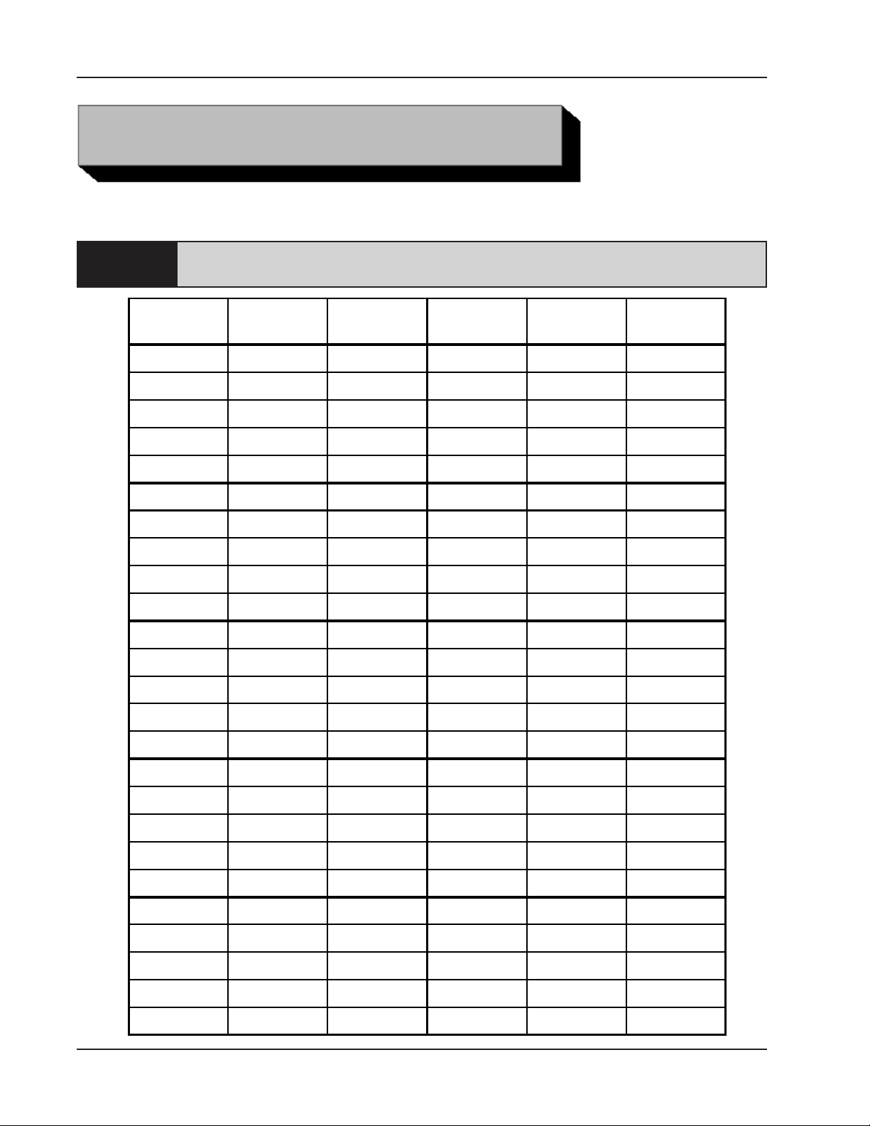
COLLETS
NOTE:
Decimal
The size of the Collet is determined by the outside diameter of the tube
or pipe to be severed or squared.
mm
Part No.
Inches
.250 6.35 30-2394 .563 14.30 30-2419
.276 7.00 30-2395 .591 15.00 30-2420
.281 7.14 30-2396 .594 15.08 30-2421
.313 7.95 30-2397 .602 15.29 30-2422
.315 8.00 30-2398 .625 15.88 30-2423
.344 8.74 30-2399 .630 16.00 30-2424
.354 9.00 30-2400 .641 16.27 30-2425
.359 9.13 30-2401 .656 16.66 30-2426
.375 9.53 30-2402 .669 17.00 30-2427
.394 10.00 30-2403 .675 17.15 30-2428
.400 10.16 30-2404 .677 17.20 30-2429
.406 10.31 30-2405 .681 17.30 30-2430
Equiv.
Decimal
Inches
mm
Part No.
Equiv.
18
.413 10.50 30-2406 .688 17.48 30-2431
.422 10.72 30-2407 .709 18.00 30-2432
.433 11.00 30-2408 .718 18.24 30-2433
.438 11.13 30-2409 .750 19.05 30-2434
.469 11.91 30-2410 .781 19.84 30-2435
.472 12.00 30-2411 .787 20.00 30-2436
.500 12.70 30-2412 .813 20.65 30-2437
.512 13.00 30-2413 .840 21.34 30-2438
.531 13.50 30-2414 .844 21.44 30-2439
.540 13.72 30-2415 .854 21.70 30-2440
.543 13.80 30-2416 .859 21.83 30-2441
.547 13.89 30-2417 .866 22.00 30-2442
.551 14.00 30-2418 .875 22.23 30-2443
92-0660 : Rev. 080423
Page 19
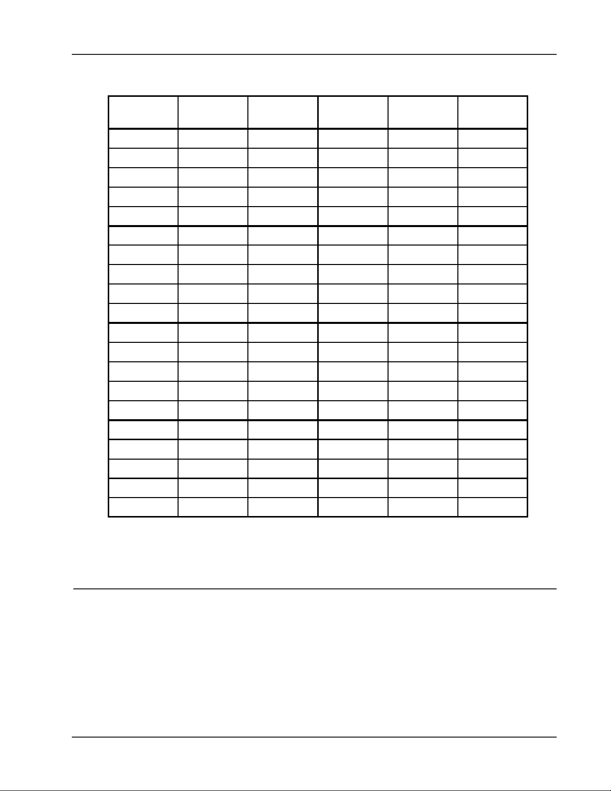
Collets, Continued
Model 572AC SEVERMASTER
TM
Decimal
Inches
.906 23.00 30-2444 1.375 34.93 30-2464
.938 23.83 30-2445 1.378 35.00 30-2465
.969 24.61 30-2446 1.438 36.53 30-2466
.984 25.00 30-2447 1.500 38.10 30-2467
1.000 25.40 30-2448 1.563 39.70 30-2468
1.024 26.00 30-2449 1.575 40.00 30-2469
1.050 26.67 30-2450 1.625 41.28 30-2470
1.063 27.00 30-2451 1.660 42.16 30-2471
1.071 27.20 30-2452 1.681 42.70 30-2472
1.102 28.00 30-2453 1.688 42.88 30-2473
1.125 28.58 30-2454 1.750 44.45 30-2474
1.142 29.00 30-2455 1.752 44.50 30-2475
1.181 30.00 30-2456 1.813 46.05 30-2476
1.188 30.18 30-2457 1.875 47.63 30-2477
mm
Equiv.
Part No.
Decimal
Inches
mm
Part No.
Equiv.
1.250 31.75 30-2458 1.900 48.26 30-2478
1.260 32.00 30-2459 1.913 48.60 30-2479
1.313 33.35 30-2460 1.938 49.23 30-2480
1.315 33.40 30-2461 1.969 50.00 30-2481
1.327 33.70 30-2462 2.000 50.80 30-2482
1.339 34.00 30-2463
Spare parts for the Collets are:
Item Part
No. No. Description Qty
1. 28-0260 O-RING, SMALL 1
2. 28-0261 O-RING, LARGE 1
3. 40-0236 SPRING, COMPRESSION, .25" DIA 3
92-0660 : Rev. 080423
19
Page 20
TRI TOOL INC.
TOOL BITS
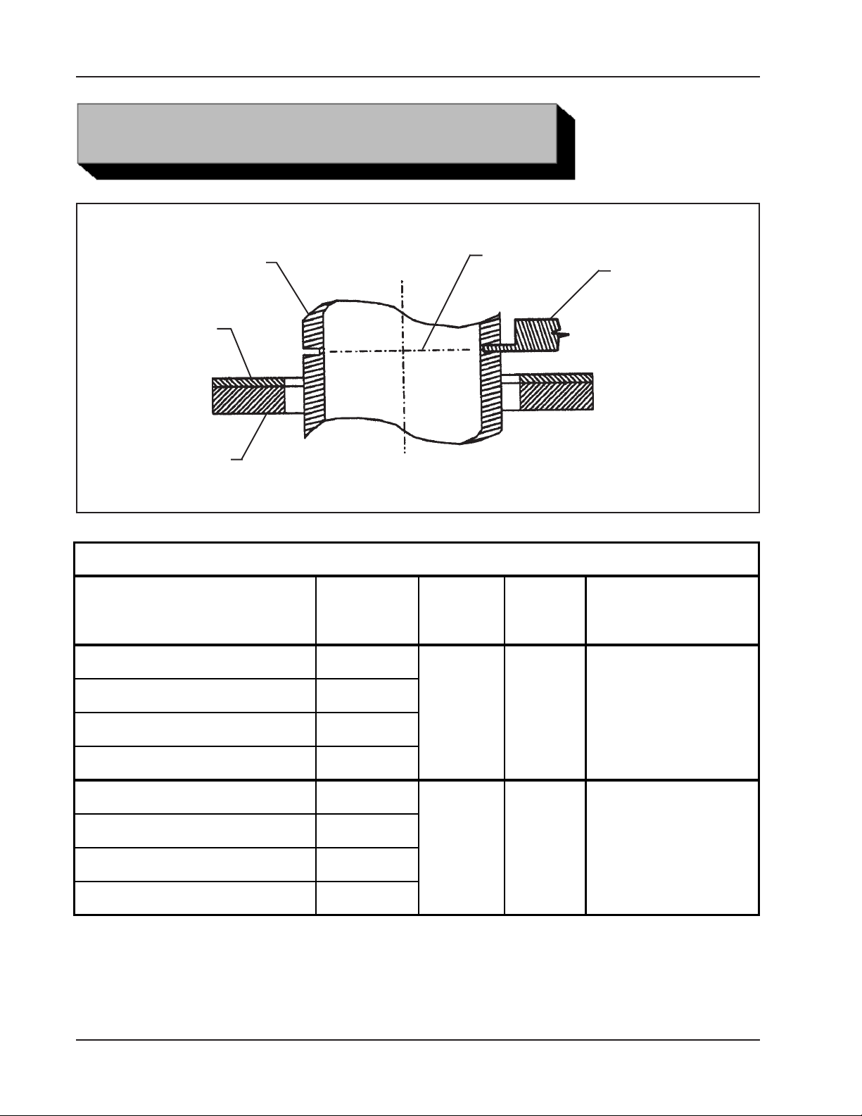
Sever Tool Bit for Light Wall Pipe or Tube
Pipe or Tube
HEADSTOCK
SEVERMASTER
TM
Tool Bit Selection
Max. Wall
Range
Thickness
1/8" thru 3/8" pipe Sch 10
Pipe
or Tube
Material
Sever Line
Sever
Tool Bit
P/N
Sever Tool Bit
Notes
1/2" thru 1 1/2" pipe Sch 5
1/4" dia thru 2" dia tube .065"
6.4 mm dia thru 50.8 mm dia 1.65 mm
1/8" thru 3/8" pipe Sch 10
1/2" thru 1 1/2" pipe Sch 5
1/4" dia thru 2" dia tube .065"
6.4 mm dia thru 50.8 mm dia 1.65 mm
20
CS, SS 99-2959
CS, SS 99-3036
92-0660 : Rev. 080423
A bur will be left
on the side opposite
from the headstock
A bur will be left
on the same side
as the headstock
Page 21

Model 572AC SEVERMASTER
TROUBLE SHOOTING
Problem: The Tool Bit Chatters
Probable causes:
The tool bit is loose or overextended.
The tool bit is damaged.
The tool holder is too loose in the slides.
The cutting speed is too fast.
The clamping pads are loose on the pipe or tube.
Cutting fluid is required.
The main bearing pre-load is loose.
Problem: There is excessive Tool Bit wear
TM
Probable causes:
The pipe or tube material is too hard or abrasive.
The cutting speed is too fast.
Cutting fluid is required.
A dull Tool Bit is causing surface hardening conditions (Stainless pipe or tubing).
There is scale or other foreign matter on the pipe or tube, which is dulling the tool bit
at the start of the cut.
The tool bit is incorrect for the material being cut.
Problem: The surface finish is rough
Probable causes:
The tool bit is dull, chipped, etc.
Metal build-up on the cutting edge of the tool bit is creating a false cutting edge.
Cutting fluid is required.
The cutting speed is incorrect.
Problem: The tool holder is not feeding
Probable causes:
The feed pin is broken or out of position.
The feed sprocket shear pin is broken.
The feed screw is stripped.
The feed nut is stripped.
The slide rails are too tight.
92-0660 : Rev. 080423
21
Page 22

TRI TOOL INC.
Problem: There is a loss of air power
Probable causes:
The air supply pressure is too low.
The air filter is plugged.
The air line size is insufficient.
The air line is too long.
Problem: There is a loss of hydraulic power
Probable causes:
The hydraulic supply pressure is too low.
The hydraulic filter is plugged.
The hydraulic line size is insufficient.
The hydraulic line is too long.
Problem: The tool bit will not reach the work
Probable causes:
Incorrect tool blocks are installed for the size of the pipe or tube being worked on.
Incorrect tool bit is installed.
Problem: The hydraulic motor will not start
Probable causes:
The hydraulic power supply is shut off.
The hydraulic motor is damaged and will not run free.
22
92-0660 : Rev. 080423
Page 23
Model 572AC SEVERMASTER
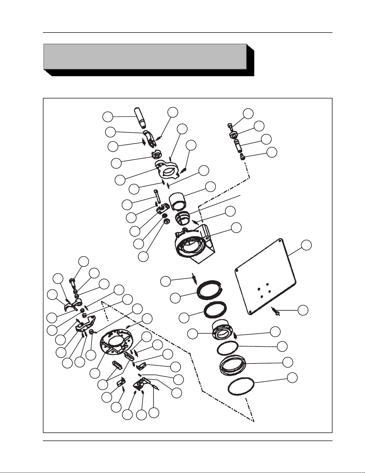
ILLUSTRATED PARTS BREAKDOWN
MODEL 572AC, SEVERMASTERTM ASSEMBLY
TM
57
46
39
47
56
41
4
53
23
28
24
8
42
5
50
16
35
43
16
25
32
19
27
29
17
52
15
21
44
14
36
48
6
13
COLLET
1
7
40
51
34
2
38
49
30
9
58
54
36
31
92-0660 : Rev. 080423
26
18
45
35
37
54
55
20
10
22
12
3
11
23
Page 24

TRI TOOL INC.
Parts List, Model 572AC Sub-Assembly (P/N 02-2221)
Item Part
No. No. Description Qty
1. 19-0759 HOUSING, MAIN 1
2. 19-0761 HOUSING, FEED 1
3. 20-0632 SHAFT, MAIN 1
4. 20-0633 SHAFT, CLAMP 1
5. 20-0635 SHAFT, CAM 1
6. 20-0637 SHAFT, TRIPPER 1
7. 24-1479 PLATE, STAND 1
8. 24-1481 PLATE, CLAMP 1
9. 24-1482 PLATE, MAIN 1
10. 27-0556 ADAPTER, COLLET 1
11. 28-0256 O-RING 1
12. 28-0257 O-RING 1
13. 29-0031 BEARING, CAM FOLLOWER 1
14. 29-0348 BEARING, ROLLER 1
15. 30-0125 PLUNGER, BALL 1
16. 30-2490 CLUTCH, ROLLER 2
17. 32-0116 PIN, DOWEL, 1/4" DIA X 1/2" 2
18. 32-0140 PIN, DOWEL, 1/4" DIA x 3/4" 2
19. 32-0495 PIN, DOWEL, 5/16" DIA X 3/4" 1
20. 32-0497* PIN, STOP 1
21. 33-0013 SCREW, CAP, #6-32 X 1/2" 8
22. 33-0028 SCREW, CAP, #10-24 X 1/2" 8
23. 33-0031 SCREW, CAP, #10-24 X 7/8" 2
24. 33-0039 SCREW, CAP, 1/4-20 X 5/8" 4
25. 33-0489 SCREW, SET, #10-24 X 5/16", CUP PT 1
26. 33-0514* SCREW, SET, 5/16-18 X 3/8", CUP PT 2
27. 33-0954 SCREW, SET, #10-24 X 1/4", HDOG 2
28. 33-1391 EYEBOLT 1
29. 33-1979 SCRW, SHOULDER, 5/16" X 2" 1
30. 33-1985 SCREW, CAP, #10-32 X 1/2", BRASS TIP 1
31. 33-1986* SCREW, SET, 5/16-18 X 1/2", CONE PT 2
32. 33-1987 SCREW, SET, 5/16-18 X 3/4", HDOG 2
34. 33-1998 SCREW, SET, 5/16-18 X 3/4", HD, LOCK 1
35. 33-2000 SCREW, CAP, SS, #10-24 X 1/2" 8
36. 33-2001 SCREW, CAP, SS, #10-24 X 3/4" 3
37. 33-2002 SCREW, CAP, SS, #10-24 X 7/8" 6
38. 33-2003 SCREW, CAP, SS, 1/4-20 X 1 1/4" 2
39. 33-0203 SCREW, CAP, #10-32 X 7/8" 1
40. 33-2005 SCREW, FLAT HEAD, SS, 5/16-18 X 3/4" 4
24
92-0660 : Rev. 080423
Page 25

Model 572AC SEVERMASTER
Parts List, Model 572AC Sub-Assembly (P/N 02-2221), Continued
Item Part
No. No. Description Qty
41. 33-2006 SCREW, BUTTON HEAD, SS, 3/8-16 X 1" 1
42. 34-0134 WASHER SET, SELF ALIGN, 3/8" 1
43. 35-0139 NUT, CHECK 1
44. 39-0805 GEAR, WORM, 60T 1
45. 40-0233 SPRING, COMPRESSION 2
46. 40-0246 SPRING, COMPRESSION 1
47. 41-0125 HANDLE 1
48. 42-0023 KNOB 1
49. 42-0171 KNOB, FEED SHAFT 1
50. 45-0260 BUSHING, BRONZE 1
51. 45-0261 BUSHING, BRONZE 1
52. 46-0439 SLEEVE, PUSHER 1
53. 47-1099 BRACKET, HINGE 1
54. 48-1017 BLOCK, SPRING 2
55. 48-1018 BLOCK, TOOL HOLDER 1
56. 62-0106 CAM, CLAMP 1
57. 63-0137 ARM, FEED 1
58. 66-0159 RAIL, SLIDE 2
TM
* These parts are recommended for spare parts.
92-0660 : Rev. 080423
25
Page 26
TRI TOOL INC.
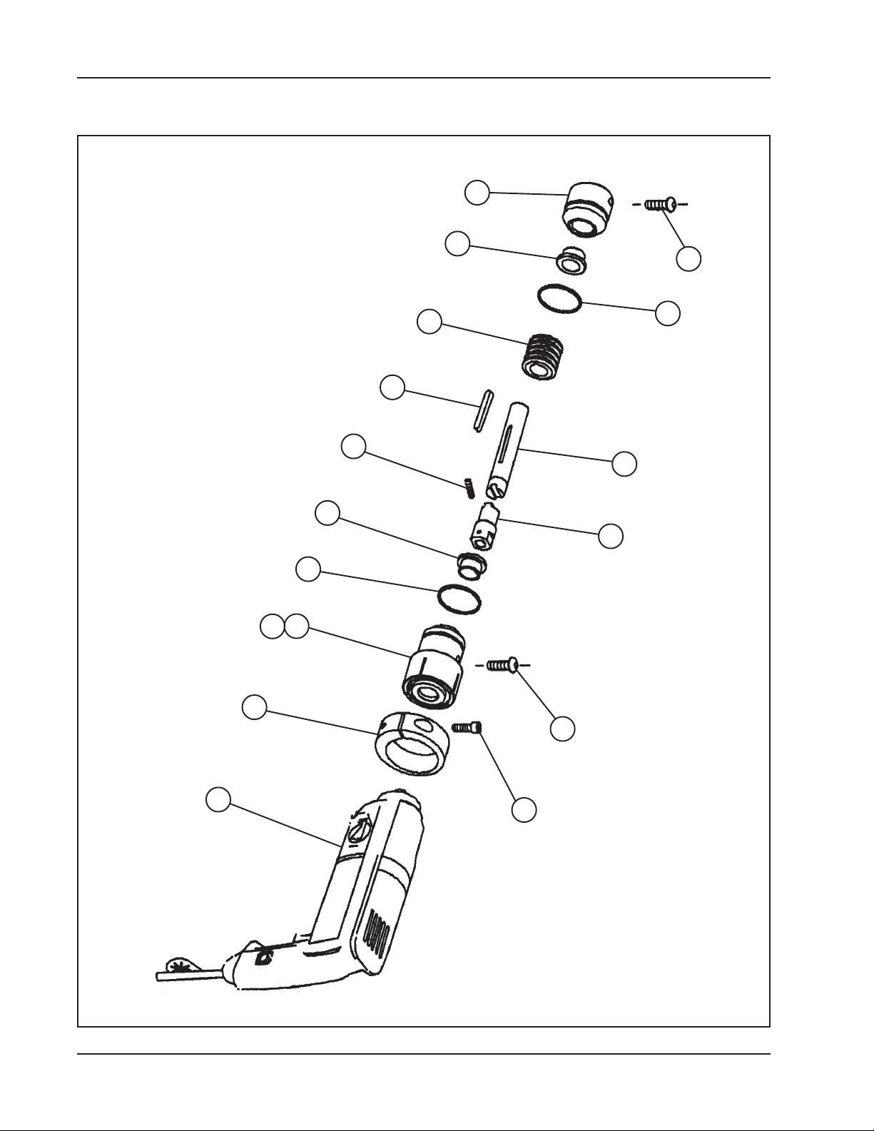
ELECTRIC MOTOR ASSEMBLY
13
10
7
12
9
5
8
1
10
2
4
3
11
7
4
26
14
6
92-0660 : Rev. 080423
Page 27

Model 572AC SEVERMASTER
Parts List, Drive Assembly, Electric, 110 VAC (P/N 58-0076)
Item Part
No. No. Description Qty
1. 20-0617 SHAFT, DRIVE 1
2. 20-0619 SHAFT, DRIVE 1
3. 28-0245 SEAL, GREASE 1
4. 28-0233 O-RING 2
5. 31-0115 KEY 1
6. 33-0041 SCREW, CAP, 1/4-20 X 7/8" 1
7. 33-0292 SCREW, BUTTON HEAD, 5/16-18 X 5/8" 2
8. 33-0619 SCREW, SET, #10-32 X 1/4", CUP PT 2
9. 39-0005 WORM 1
10. 45-0258 BUSHING, FLANGE 2
11. 46-0411 SLEEVE, MOTOR 1
12. 47-1111 BRACKET, CLAMP 1
13. 54-0347 PLUG 1
14. 58-0011 MOTOR, ELECTRIC, 110 VAC, (Bosch) 1
TM
Parts List, Drive Assembly, Electric, 220 VAC (P/N 58-0080)
Item Part
No. No. Description Qty
1. 20-0617 SHAFT, DRIVE 1
2. 20-0619 SHAFT, DRIVE 1
3. 28-0245 SEAL, GREASE 1
4. 28-0233 O-RING 2
5. 31-0115 KEY 1
6. 33-0041 SCREW, CAP, 1/4-20 X 7/8" 1
7. 33-0292 SCREW, BUTTON HEAD, 5/16-18 X 5/8" 2
8. 33-0619 SCREW, SET, #10-32 X 1/4", CUP PT 2
9. 39-0005 WORM 1
10. 45-0258 BUSHING, FLANGE 2
11. 46-0411 SLEEVE, MOTOR 1
12. 47-1111 BRACKET, CLAMP 1
13. 54-0347 PLUG 1
14. 58-0232 MOTOR, MOD., ELECTRIC, 220 VAC, (Bosch) 1
92-0660 : Rev. 080423
27
 Loading...