

Page 1
HUMBER
Dual Control
Mixer shower
Fixed head
Installation
and
Operating
Instructions
Installers please note these InstructIons are to be left wIth the user
2180596B January 2009
Page 2

Dual control mixer
To check the product suitability for commercial and multiple installations, please contact Triton’s
specification advisory service before installation.
Telephone:
Facsimile:
E mail:
0844 980 0730
0844 980 0744
technical@tritonshowers.co.uk
CONTENTS Page
Introduction ................................................................................... 1
Safety warnings .............................................................................. 1
Main components and pack contents ............................................. 2
Site requirements ........................................................................... 3
Typical suitable installations ......................................................... 4 − 5
Temperature adjustment range ....................................................... 6
Instantaneous water heaters appliance
capabilities ......................................................................................
Preparing the mixer valve ............................................................... 7
Siting the shower ........................................................................... 7
Installation
General .............................................................................. 8 − 9
Solid wall ............................................................................. 10
Hollow wall .......................................................................... 11
Cubicle or panel .................................................................. 12
Connecting the supply pipes ......................................................... 13
Outlet adaptor ............................................................................... 13
Fitting the fixed head .................................................................... 14
Using the tiling shroud .................................................................. 15
Fitting the faceplate and knobs ................................................. 15 − 16
Commissioning .............................................................................. 17
Operating the shower.................................................................... 18
Adjusting the showerhead ............................................................. 18
Cleaning ........................................................................................ 19
Maintenance ............................................................................. 20 − 21
In-service testing ........................................................................... 21
Inspection and maintenance record ............................................... 22
Spare parts ................................................................................ 23 − 24
Fault finding .................................................................................. 25
Guarantee, service policy, etc. ..................................................rear cover
6
Page 3

Dual control mixer
INTRODUCTION
This book contains all the necessary fitting
and operating instructions for your Unichrome
Humber dual control mixer shower. Please read
them carefully.
Read through the whole of this book before
beginning your installation.
The shower installation must be carried out by
a suitably competent person and in sequence of
this instruction book.
Care taken during the installation will make sure
a long and trouble free life from the shower.
This thermostatic shower valve has been
independently tested and approved to all the
requirements of NHS Estates Model Engineering
Specification D08 Thermostatic Mixing
Valves (Healthcare Premises) to the following
designations and for the following applications:
HP-S Shower with supply pressures of
1 − 5 Bar and unrestricted flow rate.
LP-S Shower with supply pressures of
0.2 − 1 Bar and unrestricted flow rate.
For best performance within the specified
running pressure range a minimum flow of
8 litres per minute should be available to both
inlets.
The valve is suitable for fully modulating type
combination boilers and multi-point hot water
heaters. It is also suitable for thermal storage,
unvented systems and pumped gravity systems.
The valve unit can be fitted in any orientation.
For a wall mounted showerhead installation, the
plumbing will be simplified if the outlet is fitted
upwards.
The valve is supplied with an integral single
check valve and integral large area filter on each
inlet.
Inlet connections are by compression fittings for
15mm copper pipe.
This valve unit is supplied with a mounting
bracket to suit installation in a chased out cavity
in a solid wall, a stud partition wall, dry lined
wall or fixing to a shower cubicle or panel. It
is also supplied with an attached tiling shroud
which provides protection for the unit.
SAFETY WARNINGS
1 Layout and sizing of pipework MUST be
such that when other services are used,
pressures at the shower control inlets do not
fall below the recommended minimum.
2 DO NOT choose a position where the
shower could become frozen.
3 The outlet of this appliance MUST NOT be
connected to any form of tap or fitting not
recommended by the manufacturer.
4 The showerhead cartridge MUST be cleaned
regularly to remove scale and debris.
5 Conveniently situated isolating valves
in each inlet supply MUST be fitted as
an independent method of isolating the
shower should maintenance or servicing be
necessary.
6 If it is intended to operate the shower in
areas of hard water it is advisable to fit a
scale inhibitor (see note below).
7 If it is intended to operate the shower
outside the guidelines laid out in the
requirements then see note below.
Note: In the event of items 2, 6 and 7, contact
Customer Service for advice.
Replacement parts can be ordered from Triton
Customer Service. See ‘spare parts’ for details and part
numbers.
Due to continuous improvement and updating,
specification may be altered without prior notice.
1
Page 4
Dual control mixer
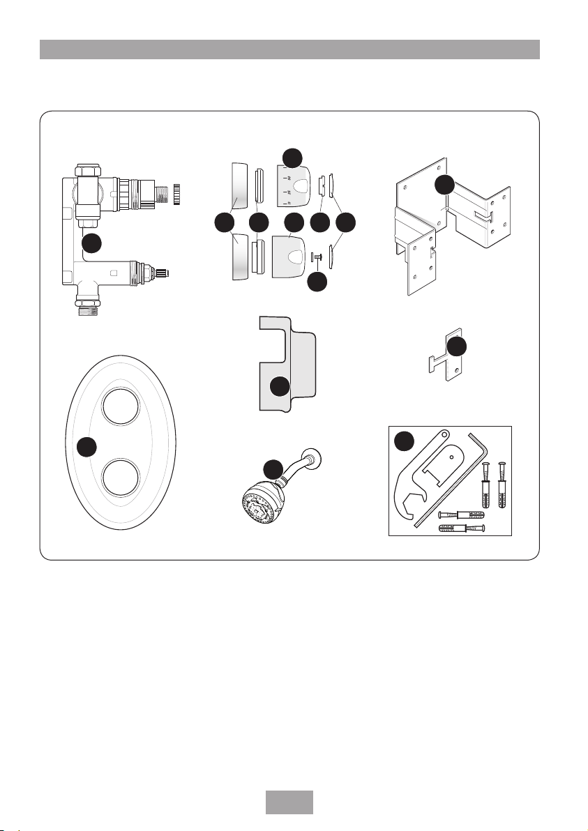
MAIN COMPONENTS and PACK CONTENTS
Fig.1
3
45 76 8
1
9
10
11
12
2
Ref Description
1 Mixer valve body
2 Face plate
3 Temperature control knob
4 On/off control knob
5 Trim rings
6 Brass retaining rings
7 Finishing caps
14
13
Ref Description
8 Locknut
9 Screw and washer
10 Tiling shroud
11 Mounting bracket
12 Flat bracket – 2 off
13 Fixed head assembly
14 Tool and screw pack
2
Page 5

Dual control mixer
SITE REQUIREMENTS
The installation must be in accordance with local
Water Company Regulations.
Minimum running water pressure: 0.2 bar.
Maximum running water pressure: 5 bar.
Maximum static water pressure: 10 bar.
For best performance within the specified running
pressure range a minimum flow of 8 litres per
minute should be available to both inlets.
While the mixer valve is operational (open
outlet), inlet pressures must not be capable of
exceeding 7 bar. For effective operation of the
internal seals, the maximum static pressure must
not be exceeded.
Note: On sites where the running pressure is
above 5 bar, the use of a suitably sized pressure
reducing valve fitted in the cold mains supply
pipework can provide nominally equal pressures
at the mixer valve.
For ideal performance of this shower both the
hot and cold water supplies to the shower valve
should be fed at nominally equal pressures.
The pipework should be installed such that the
flow is not significantly affected by other taps
and appliances being operated elsewhere on the
premises.
Note: Where thermal store/combi boilers or
multi-point heaters are used, if excessive drawoffs take place the boiler may not be able to
maintain an adequate output temperature.
This could result in the shower temperature
becoming noticeably cooler.
Water temperature requirements
Maximum hot water temperature 80°C
Recommended maximum 65°C
Minimum hot water temperature 52°C
Maximum cold water temperature 20°C
BS 6700 recommends that the temperature of
stored water should never exceed 65°C.
A stored water temperature of 60°C is
considered sufficient to meet all normal
requirements and will minimise the affects of
scale in hard water areas.
DO NOT use jointing compounds on the
pipework.
3
Page 6
Dual control mixer
Service
valves
Balanced cold mains supply
Cold mains supply
Mixer
shower
Expansion
vessel
Pressure
reducing valve
Pressure
reducing valve
Stop tap
Unvented
hot water
storage unit
Safety devices
not shown
CH flow
Cold
mains
supply
Hot water
Expansion
vessel
CH return
Service
valves
Shower
mixer
valve
Stop tap
Pressure
reducing valve
Combination
boiler
Fig.2 (diagrammatic view – not to scale)
Fig.3 (diagrammatic view – not to scale)
TYPICAL SUITABLE INSTALLATIONS
a) Instantaneous gas-heated systems,
e.g. combination boilers (fig.2)
The shower control must be installed with a
multipoint gas water heater or combination
boiler of a fully modulating design (i.e.
to maintain relatively stable hot water
temperatures).
A drop tight pressure reducing valve must
be fitted if the supply pressures exceed 5 bar
running.
An expansion vessel (shown in fig.2) must be
fitted, and regularly maintained, to make sure
the shower mixer is not damaged by excess
pressures. This may already be installed within
the boiler (check with manufacturer) and is in
addition to the normally larger central heating
expansion vessel.
The layout and sizing of pipework must be
such that nominally equal inlet supply pressures
are achieved and the effects of other draw-offs
are minimised. The hot supply temperature
must remain a minimum of 10°C hotter than
the required blend temperature for best
performance.
b) Unvented mains pressure systems
(fig.3)
The shower control can be installed with an
unvented, stored hot water cylinder.
For systems with no cold water take off after the
appliance reducing valve, it will be necessary to
fit an additional drop tight pressure reducing
valve when the mains pressure is over 5 bar.
The drop tight pressure reducing valve must be
set at the same value as the unvented package
pressure reducing valve.
Note: An additional expansion vessel (fig.3)
may be required if a second pressure reducing
valve is installed. This does not apply to
packages with a cold take off after the pressure
reducing valve to the cylinder.
The layout and sizing of pipework must be such
that nominally equal inlet supply pressures are
achieved and the effects of other draw-offs are
minimised.
4
Page 7
Dual control mixer
2 metres
minimum
Isolating
valves
Other draw-offs
Gate
valve
Vent pipe
tee
Cold supply
Hot
supply
Alternative
connection
Mixer valve
Stop
tap
Cold
water
mains
supply
Drain
valve
Cold water
cistern
Hot
water
cylinder
Blender
valve
Flow
Cold mains supply
Hot water
Stop tap
Expansion vessel
Pressure
reducing valve
Return
Service
valves
Mixer
valve
Boiler
c) Mains pressurised thermal store
systems (fig.4)
Packages of this type, fitted with a tempering
valve (blender valve) can be used. A drop tight
pressure reducing valve must be fitted if the
supply pressures exceed 5 bar running.
An expansion vessel (shown in fig.4) must be
fitted, and regularly maintained, to ensure the
unit is not damaged by excess pressures. This
may already be installed externally or internally
within the thermal store (check with thermal
store manufacturer).
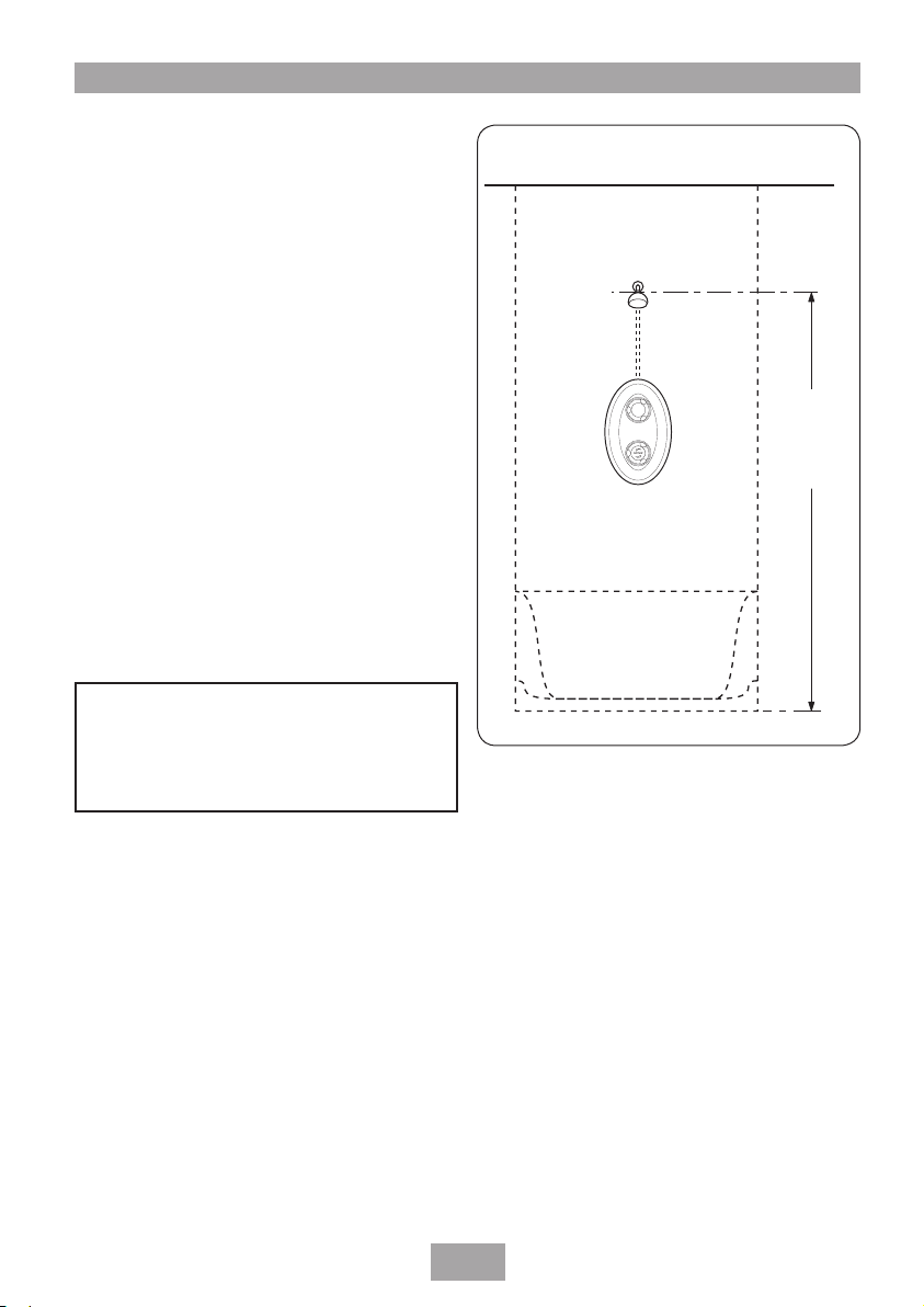
d) Gravity fed systems (fig.5)
The shower control MUST be fed from a cold
water cistern and hot water cylinder providing
nominally equal pressures. There must be a
minimum of two metres head of water. The
minimum head distance is measured from the
base of the cold water cistern to top of the fixed
head shower arm (fig.5).
DO NOT use jointing compounds on pipework.
Fig.4 (diagrammatic view – not to scale)
Fig.5 (diagrammatic view – not to scale)
5
Page 8
Dual control mixer
Flow regulator
Fig.6
TEMPERATURE ADJUSTMENT
RANGE
The mixed water temperature can be adjusted
from cold through to a top limit (which can
be preset during installation – factory set
at approximately 39°C) with full anti-scald
protection throughout the range.
INSTANTANEOUS WATER HEATERS
APPLIANCE CAPABILITIES
In order to provide the best performance from
the shower when connected to an instantaneous
water heater, the appliance must be capable of
raising the temperature of the incoming water
by 45°C (81°F) and delivering a flow rate of not
less than 8 litres per minute.
A flow regulator is supplied for fitting into the
fixed head which controls the maximum flow
through an instantaneous water heater and the
shower valve to 8 litres per minute. To fit the
flow regulator, unscrew the adjustable head from
the fixed arm. Insert the flow regulator, flat face
up, into the end of the fixed arm (fig.6). Refit
the adjustable head to the fixed arm assembly.
With the flow regulator fitted and when the
system is in use, the On/Off flow control should
be turned fully anti-clockwise to the full flow
setting.
6
Page 9
Dual control mixer
Height of
showerhead
and shower
to suit user’s
requirement.
PREPARING THE MIXER VALVE
Check the contents to make sure all parts are
present.
Make sure the supplied metal fixing bracket,
tiling shroud, cranked spanner, lock nut key and
Allen key are all to hand.
Before installing, make sure all the openings
on the valve are carefully covered to stop the
ingress of any debris, etc.
The valve unit is supplied with a mounting
bracket for installing into a chased out cavity in
a solid wall, a stud partition wall, dry lined wall
or fixing to a shower cubicle or panel. It is also
supplied with an attached tiling shroud which
provides protection for the valve both for transit
and on site. It should be left in place until the
installation is complete.
The hot and cold water pipes should not be
permanently attached to the wall closer than 2m
from the valve prior to installation. This allows
for final adjustment of the valve position.
SITING OF THE SHOWER
WARNING!
The shower must not be positioned
where it will be subjected to
freezing conditions.
Fig.7 (diagrammatic view – not to scale)
Refer to (fig.7) for correct siting of the shower.
Position the shower and showerhead on the wall
so that all controls can be comfortably reached
while using the shower.
The valve unit can be fitted in any orientation.
For a wall mounted showerhead installation, the
plumbing will be simplified if the outlet is fitted
upwards.
7
Page 10

Cold water supply
Hot water supply
Thermostatic
assembly
On/Off
assembly
Swivel inlet
(Do not tighten
against body)
Mixed water
outlet
115 mm
pipe centres
H
H
H
Outlet
C
C
C
H
Outlet
Outlet
Outlet
C
Fig.8
Fig.9
Dual control mixer
INSTALLATION
a) General conditions
Note: The outlet of the shower MUST
NOT be connected to any tap or fitting not
recommended by Triton Plc.
DO NOT use jointing compounds on any pipe
fittings for the installation.
Use only the compression fittings supplied.
DO NOT solder fittings near to the shower
unit as heat can transfer along pipework and
damage components.
Note: Suitable isolating valves (complying
with Water regulations) MUST be fitted on the
hot and cold water supplies to the shower as
an independent means of isolating the water
supplies should maintenance or servicing be
necessary.
When connecting pipework avoid using tight
90° elbows. Swept or formed bends will give the
best performance.
The valve unit can be fitted in any orientation
(fig.8), but for a wall mounted showerhead
installation, the plumbing will be simplified if the
outlet is fitted upwards. Access to the integral
strainers will also be improved with this layout.
The hot water inlet is identified with a red mark,
the cold water inlet with a blue mark. The swivel
inlets allow for either rising or falling hot and
cold water supplies. Note the swivel inlets have
‘O’ seals to the body and do not require PTFE
tape or other means of sealing.
Gently screw the swivel inlets into the body of
the valve unit and stop as soon as resistance is
felt. Then back off by up to 1.5 turns to align
the inlet with the hot and cold supply pipes.
IMPORTANT: The swivel inlets MUST NOT be
tightened against the valve body to make a
seal (fig.9).
The Triton dual control mixer valve includes a
mounting bracket which allows the installer to
mount the shower into a solid, stud partition or
other hollow wall structures. The bracket can
also be used for fitting in a shower cubicle or
panel providing the back of the cubicle or panel
is accessible.
8
Page 11

Dual control mixer
Wall surface
Tolerance
for varying
tile thickness
Tiles
65 mm
When installing into a stud partition or other
hollow wall structure the installer may wish to
consider building rear supports or other options.
Such options are beyond the scope of this guide.
Before installing, make sure the available depth
of recess or cavity is at least 65 mm (fig.10)
measured from the face of the wall upon which
the mounting bracket is screwed (excluding the
tile thickness).
The allowance for varying thickness of tiles up to
10 mm is accommodated by a limited degree of
tolerance between the control knobs and their
trim rings.
If the valve unit is to be fitted behind an existing
wall panel, use the supplied self-adhesive
template as a guide when cutting the opening.
Fig.10
9
Page 12

Dual control mixer
135 mm
maximum
235 mm
maximum
Fig.11
Fig.12
Fig.13
b) Valve installation in solid wall
Remove the tiling shroud, if fitted, from the
valve unit. The shroud is retained by a 2.5 mm
hex socket screw; replace the screw in the valve
immediately to avoid it being lost.
Decide on the shower position and determine
whether the hot and cold water supplies will
enter the shower from the top (falling) or
bottom (rising) or rear.
The building depth should be at least 70 mm
deep from the surface of the wall. It is
recommended to use the supplied mounting
bracket (fig.11) at all times when installing
the shower valve. It provides the correct visible
amount of shower control through the faceplate
when the installation is complete. There is
limited tolerance between the control knobs and
trim rings to allow for varying thickness of tiles
up to 10 mm.
As a guide for the size of hole, place the tiling
shroud on the wall and trace around it (fig.12).
Remove the plaster and brickwork to the
required depth and chase out any additional
areas of the wall to allow for the pipework to
and from the valve.
Offer the mounting bracket up to the wall
and mark the four outer plain holes (fig.13).
Remove the bracket then drill and plug the
wall. Screw the bracket to the wall. Route the
pipework to valve position.
Flush out the pipework in accordance with
Water Regulations.
Offer the valve up to the mounting bracket, and
secure using the four screws provided.
Proceed to ‘Connecting supply pipes’ section.
10
Page 13

Dual control mixer
Flat bracket
positioned inside
of panel
c) Valve installation in a hollow wall
The wall mounting bracket supplied with the
shower is suitable for use on a plasterboard wall
of 10 mm to 15 mm thickness.
Decide on the shower position and determine
whether the hot and cold water supplies will
enter the shower from the top (falling) or
bottom (rising) or rear.
The hollow cavity should be at least 65 mm
deep from the surface of the wall. It is
recommended to use the supplied mounting
bracket (fig.14) at all times when installing
the shower valve. It provides the correct visible
amount of shower control through the faceplate
when the installation is complete. There is
limited tolerance between the control knobs and
trim rings to allow for varying thickness of tiles
up to 10 mm.
Mark the route of the incoming and outgoing
pipework. As a guide for the size of hole, place
the tile shroud on the wall and trace around it
(fig.12).
Take out the plasterboard and offer the
mounting bracket up to the wall and mark the
four outer plain holes (fig.14). Remove the
bracket and drill the wall.
Two additional flat brackets are supplied for
hollow wall fixing. Slide the ‘T’ piece section
through the slot either side of the mounting
bracket then insert it into the wall cavity.
Position the two flat brackets in line with the
outer holes (fig.15). Secure using the bolts
provided. Route the pipework to the valve
position.
Flush out the pipework in accordance with
Water Regulations.
Offer the valve up to the mounting bracket and
secure using the four screws provided.
Proceed to ‘Connecting supply pipes’ section.
Fig.14
Fig.15
11
Page 14

Dual control mixer
Flow
Temperature
99 mm
centres
33 mm
dia
43 mm
dia
Panel
surface
Blocks
70.5 to 76.5 mm
Fig.16
Fig.17
Fig.18
d) Valve installation in a panel or
cubicle
To use the wall mounting bracket supplied with
a shower cubicle or a laminated panel, wooden
blocks are required to increase the depth of
the bracket. These blocks need to increase the
depth of the bracket to between 70.5 mm and
76.5 mm from the finished surface (fig.16).
Decide on the shower position and determine
whether the hot and cold water supplies will
enter the shower from the top (falling) or
bottom (rising) or rear.
Mark the route of the incoming and outgoing
pipework. Only the two holes for the controls
knobs require to be cut out of the panel or
cubicle. Use the supplied template as a guide
(fig.17).
After cutting the two holes, fit the valve to the
mounting bracket and secure using the four
screws provided.
Offer the valve and mounting bracket up to the
back of the panel making sure the thermostatic
and On/Off assemblies fit through the openings.
Mark the four inner tapped holes (fig.18).
Remove the valve and bracket and drill the panel
and wooden blocks. Route the pipework to valve
position.
Flush out the pipework in accordance with
Water Regulations.
Fit the mounting bracket together with the valve
to the panel and secure using the bolts and
washers provided.
Proceed to ‘Connecting supply pipes’ section.
12
Page 15

Dual control mixer
Hose end
(flat)
Pipe end
(chamfered)
CONNECTING THE SUPPLY PIPES
Gently screw the swivel inlets into the body of
the valve unit and stop as soon as resistance is
felt. Then back off by up to 1.5 turns to align
the inlet with the hot and cold supply pipes.
IMPORTANT: The swivel inlets MUST NOT be
tightened against the valve body to make a
seal.
Connect the hot water supply to the inlet
marked RED, and connect the cold water supply
to the inlet with the BLUE mark.
Remember the swivel inlet has an ‘O’ ring seal
and that no other sealing means is required.
Tighten the compression fittings with the
cranked spanner, supplied for when access is
restricted.
Make sure the On/Off assembly is turned to the
off position by temporarily fitting the On/Off
control and turning clockwise until resistance is
felt.
Open the supplies and test for leaks in the
pipework upstream of the valve.
OUTLET ADAPTOR
The mixed water outlet adaptor needs to be
removed and replaced using PTFE tape to give a
watertight seal.
Note: The outlet adaptor is reversible with one
side suitable for connection to a flexible hose
– flat end (fig.19), and the other is a chamfered
end for a 15 mm compression fitting (fig.19).
Fig.19
13
Page 16

Dual control mixer
Appropriate
fitting
Water pipe
Connector
Fitting should
be flush with
the finished wall
Fig.20
Fig.21
FITTING THE FIXED HEAD
Complete the pipework leading to the shower
arm with a 15 mm x ½" BSP female thread
elbow (fig.20) or similar. Finish the wall so that
it is flush with the fitting.
Note: This fitting is not supplied as variations
in installations require the selection of a suitable
solder or compression fitting.
Screw the supplied male-thread connector into
the female fitting (fig.21) using PTFE tape to
give a watertight joint.
Slide the arm onto the connector temporarily,
and mark the position of the three retaining
screws. Remove the arm then drill and plug the
holes using the wall plugs supplied. (The wall
plugs provided are suitable for most brick walls
— use an appropriate masonry drill, but if the wall
is plasterboard or soft building block, you must use
special wall plugs and a suitable drill bit).
Refit the fixed arm onto the connector and
secure in place using the screws supplied.
Tighten the grub screw in the base of the arm
using an Allen key (fig.22).
Slide the cover trim onto the arm and push fit
into place before fitting the showerhead.
Fig.22
14
Page 17

Dual control mixer
Remove
shaded
area to
allow
for the
mounting
bracket
USING THE TILING SHROUD
WARNING!
Check there are no hidden cables or
pipes before drilling holes for wall
plugs. Use great care when using
power tools near water. The use of
a residual current device (RCD) is
recommended.
The tiling shroud will need a section removed
(fig.23) to accommodate the mounting
bracket.
Replace the tiling shroud over the mixer valve.
Plaster or tile up to the edge of the shroud. Note
that if the tiles are accurately cut to match the
profile of the shroud, then the faceplate will seal
around the hole in the tiles, and the valve unit
will be able to be removed from the mounting
bracket without the need to break any tiles.
Make sure the grout lines around the valve are
flush with the tiles in order to provide a smooth
sealing surface for the faceplate.
FITTING THE FACEPLATE AND
KNOBS
Unscrew the faceplate retaining rings from the
valve unit (if fitted).
See (fig.24) for the assembly of parts. Position
the faceplate over the valve unit and place the
trim rings onto the faceplate making sure the
indicator notch is in the 12 o’clock position.
It must be in this position regardless in which
orientation the unit is mounted.
Secure by screwing on the two brass faceplate
retaining rings.
Gently tighten the rings by hand until the
faceplate clamps gently against the wall.
DO NOT overtighten or the faceplate may
distort. The faceplate incorporates a silicon
sponge seal which will seal against a smooth
wall.
Fig.23
15
Page 18

Face plate
Trim ring
Trim ring
Brass
face plate
retaining ring
(small hole)
Brass face plate retaining ring
(large hole)
Temperature
control knob
Locknut
Finishing
cap
Finishing
cap
Splined
adaptor
On/off
control knob
Screw and
washer
Locknut
key
Fig.24
Dual control mixer
Should the wall surface be uneven or has deep
grout lines or other imperfections, then these
must be filled in, or use a bead of silicon sealant
around the joint between the faceplate and the
wall.
DO NOT apply this until the knobs have been
assembled onto the mixer valve and finally
completed.
Temperature control knob assembly
Place the temperature knob temporarily onto the
splined adaptor, and rotate fully anti-clockwise.
Remove the knob and reposition onto the
splined adaptor again, but this time making
sure the ‘40’ mark on the scale lines up with the
indicator notch on the trim ring. It must be held
firmly but not overtight. Make sure the knob
does not foul on the trim ring.
Screw the locknut down against the knob and
tighten using the key supplied. Do not fit the
finishing cap just yet as when the commissioning
is carried out, the maximum temperature
adjusting screw may have to be altered.
On/Off control knob assembly
Place the splined On/Off knob onto the splined
shank and secure with the washer and fixing
screw.
Push fit the finishing cap onto the on/off knob.
Note the cap with the red and blue arrows fits
on the temperature control knob and the plain
cap fits on the On/Off knob. The caps are not
interchangeable.
Note: Should the knobs and faceplate require
cleaning then care must be taken not to scratch
them in the process. Wash away any surface
dust with the shower spray before cleaning with
soapy water.
IMPORTANT: DO NOT use abrasive cleaners
and solvents or the surfaces may become
damaged.
16
Page 19

Dual control mixer
Maximum temperature
adjusting screw
COMMISSIONING
The following conforms to NHS Estates Model
Engineering Specification D08 for when the mixer
has been installed in healthcare premises.
IMPORTANT: Make sure that all supply
pipework has been flushed through before
commissioning.
Make sure that both hot and cold water supplies
are fully open and at (or near to) their design
temperature and pressures and are within the
requirements as stated.
Set the temperature control to the maximum
temperature setting – rotate the knob fully anticlockwise until resistance is felt.
Open the On/Off control by turning it anticlockwise. If a fixed head has been installed,
placing a burst polythene bag over the shower
head will catch and deflect the spray during
commissioning.
Allow the shower to run at maximum
temperature setting until the water temperature
has stabilised. Should the temperature rise in
an uncontrolled manner, then the hot and cold
supplies are probably reversed. This must be
corrected before proceeding further.
The mixer valve is factory set to provide a
maximum outlet temperature of 39°C but this
should be checked on site to make sure the
setting has not been altered and also to make
sure of user safety.
Should the maximum temperature require
adjustment, remove the temperature knob
finishing cap (if it has been placed in position
when assembling the temperature controls
previously) using a sharp blade or pen knife tip.
Adjust the small slotted screw in the centre of
the spindle (fig.25) – anti-clockwise to increase
the temperature, clockwise to decrease the
temperature.
The maximum temperature should not exceed
41°C.
After setting the maximum temperature, turn
the shower on and off several times and check
the maximum setting is correct. Record the
commissioning data on the maintenance record
at the rear of this book in order for the in-service
performance of the mixer valve to be assessed.
Fig.25
17
Page 20

Fig.26
Fig.27
Fig.28
Dual control mixer
Finally, check the thermal shut off facility of the
valve by performing a thermal shut off test. Shut
off the cold supply. The flow from the shower
should stop immediately or reduce to a trickle in
which case the water temperature should be less
than 43°C.
In either case there is no risk of scalding.
If, however, the temperature is above 43°C then
it is likely there is contamination in the valve
stopping it from shutting off the hot supply. In
this case refer to the maintenance section or
contact Customer Service.
In domestic installations where D08 specification
is not required, the maximum temperature
setting should not exceed 45°C.
OPERATING THE SHOWER
To start the shower, rotate the On/Off control
fully anti-clockwise (fig.26) for maximum flow.
To stop the water flow, rotate the On/Off control
fully clockwise (fig.27) until resistance is felt.
To adjust the water temperature, rotate the
temperature control clockwise in the direction of
the blue symbol (fig.28) for a cooler shower, or
anti-clockwise in the direction of the red symbol
(fig.29) for a hotter shower.
Fig.29
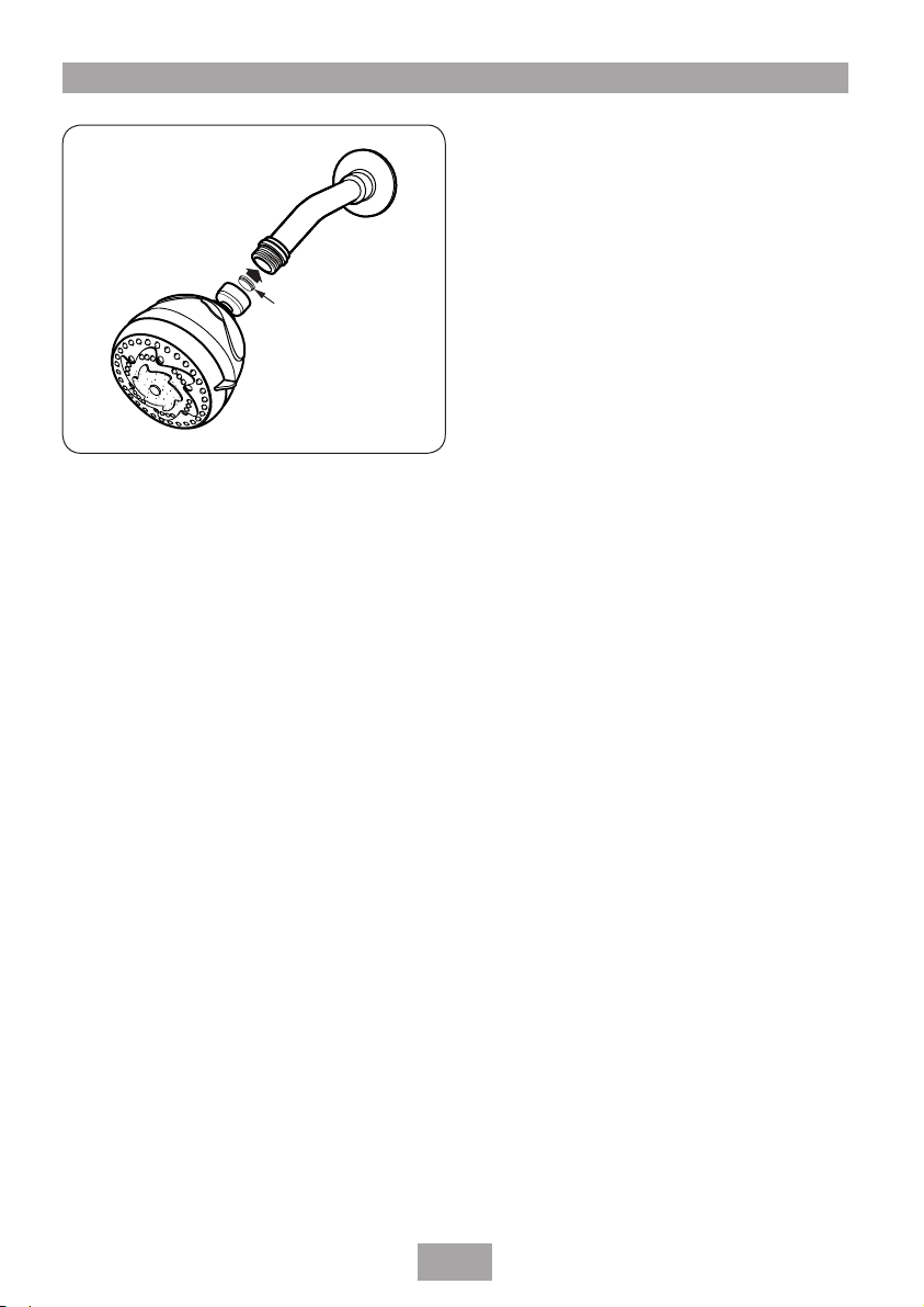
ADJUSTING THE SHOWERHEAD
Five showerhead patterns are available. Adjust
the spray pattern by turning the bezel on the
showerhead in either direction until the desired
pattern is obtained.
18
Page 21

Dual control mixer
Sprayplate
key
Sprayplate
CLEANING
WARNING!
DO NOT use ‘powerful’ abrasive or
solvent cleaning fluids when cleaning
the shower as they may damage the
plastic fittings.
Before cleaning, turn off the unit at the isolating
valve to avoid the shower being accidentally
switched on.
IT IS IMPORTANT TO KEEP THE SHOWERHEAD
CLEAN TO MAINTAIN THE PERFORMANCE
OF THE SHOWER. The hardness of the water
will determine the frequency of cleaning. For
example, if the shower is used every day in a
very hard water area, it may be necessary to
clean the showerhead on a weekly basis.
Sprayplate removal
There is no need to remove the showerhead
from the shower arm.
Using the removal tool supplied (fig.30),
locate the raised ’bosses’ into the recesses in
the sprayplate. Hold in firmly and twist anticlockwise (fig.31). This movement may turn the
cartridge assembly as well until it reaches a ‘stop’.
Hold the cartridge firmly and continue to twist
anti-clockwise. Having loosened the sprayplate,
it can be unscrewed and removed completely.
Clean the sprayplate with a suitable brush or
preferably leave it to soak overnight in a mild
proprietary descalent. Make sure all traces of
scale are removed and thoroughly rinse in clean
water afterwards.
Before replacing the sprayplate, turn on the
water supply at the isolating valve and direct the
showerhead toward the waste water outlet.
Turn the temperature control to COLD.
Start the shower and set to maximum flow. This
operation will flush out any loose scale deposits
in the unit and showerhead. Stop after about
thirty seconds.
Refit the sprayplate by screwing clockwise. Use
the tool to screw the sprayplate tight.
Fig.30
Fig.31
19
Page 22

Dual control mixer
Inlet strainer body
Strainer
basket
Swivel
seal
15mm
ferrule
15mm
compression
nut
End cap
Cap seal
On/Off unit
Seal
Retaining nut
½" Washer
Valve
cover
Piston
seal
Temp
adjustment
piston
Control
stem
Max temp
adjustment
screw
Temp knob
adaptor
Thrust
washer
Adaptor
circlip
Baffle
tube
Return
spring
Slide valve
seal
Slide valve
sub assembly
Thermostat
element
Element
spring
Valve
cover
seal
Fig.32
Fig.33
Fig.34
WARNING!
When cleaning the external faceplate
they may damage the chrome plating.
and knobs, NEVER use cleaners
containing abrasives or solvents as
Use only soap and a soft cloth.
MAINTENANCE
The following maintenance procedure must
be carried out for commercial and health care
premises, but is not necessarily required for
domestic installations.
Maintenance of the unit is required to give
continued performance after installation and
that it continues to provide scald prevention.
The frequency of routine maintenance of the
internal of the valve will depend mainly on
the water supply condition. Local knowledge
will dictate suitable intervals. In addition, the
following precautions should be noted:
a) Initially check the strainer baskets (fig.32)
for debris once every three months and
clean if necessary. This period can be
increased, if needed, once the general
condition and cleanliness of the water is
established. Where the water supplies come
from beneath (rising) the mixer valve, lifting
out the strainer basket may not remove all of
the trapped debris. Full flushing out may be
necessary if debris is found or suspected.
b) Perform a thermal shut off test every
three months, and check the maximum
temperature setting. See the ‘Commissioning’
section for the details of this test and
readjustment of the maximum temperature
setting if required.
c) If the maximum water temperature varies
by more than 2°C from the commissioned
setting then make check the strainers are
clean and that the isolating valves are fully
open. Test the non-return valves as described
below. If these tests do not highlight the
reason for the temperature variation, then
follow the procedure below for investigating
failure of the thermal shut off test.
d) If the mixer valve fails the thermal shut
off test then remove the knobs, faceplate
and control valve cover. Check the internal
surface for scaling. If the body requires
descaling then it should be removed
from the pipework to carry this work out
– the valve should be able to be removed
through the aperture without breaking tiles.
All rubber parts must be removed before
descaling. The slide valve seal (fig.35)
20
Page 23

Dual control mixer
located inside the body should always be
replaced with a new seal after removal.
Maintenance kits are available which contain
‘O’ rings and/or the thermostatic element.
Smear all ‘O’ rings with silicon grease prior
to installing them. Torque the valve cover
to 13 Nm. This is to prevent inadvertently
unscrewing the cover during temperature
adjustment. DO NOT overtighten the valve
cover or the mounting arrangement may
be damaged.
e) Replace the ‘O’ rings every three years;
maintenance kits with spare ‘O’ rings are
available. Smear silicon grease on all ‘O’
rings before assembling. At the same time,
replace the slide valve assembly (fig.33).
Lightly smear the outside diameter with
silicon grease before installing.
f) Replace the thermostatic element (fig.33)
at least once every six years, or more often if
problems are experienced or in installations
where water is particularly hard.
g) The On/Off mechanism (fig.34) has a
½” tap washer which should be replaced
when it is found to be leaking. Remove
the trim plate and unscrew the On/Off
assembly. The washer is retained by a small
nut. When replacing, do not overtighten
– torque to 25 Ncm. Make sure the On/Off
assembly is torqued down to 13 Nm to
stop the user from accidentally unscrewing
the assembly during flow control. DO NOT
overtighten the assembly or the mounting
arrangement may be damaged.
h) The non-return valves (NRVs) prevent cross-
flow between hot and cold supplies under
unequal pressure conditions. They are
designed for long life with no maintenance.
Their function can be tested as follows:
To test the NRV on the hot side, shut off
the hot supply and make sure the cold
supply is open. Be prepared for leakage of
trapped water in the pipe and remove the
strainer basket on the hot side. Evidence of
continuing leakage from the strainer body is
coming through the hot supply NRV.
To test the NRV on the cold side, shut off
the cold supply and make sure the hot
supply is open. Be prepared for leakage of
trapped water in the pipe and remove the
strainer basket on the cold side. Evidence of
continuing leakage from the strainer body is
coming through the cold supply NRV.
If either NRV is leaking then the inlet elbow
– complete with NRV and strainer basket,
should be replaced. It is not possible to
satisfactorily remove the NRV itself from the
elbow and should not be attempted.
IN-SERVICE TESTING
Periodic testing should be undertaken to check
whether deterioration has occurred in the
performance of the mixer valve.
A thermal shut off test, as described under
maintenance, should be carried out. If
water coming from the shower head is at
a temperature of more than 2°C above the
maximum mixed water temperature setting then
the valve unit is due for maintenance.
Note: A thermostatic mixing valve in need of
maintenance can be undetectable in normal
use and only becomes apparent when a
disruption occurs in the hot or cold water supply
temperatures or pressures.
The frequency of in-service testing depends
upon the water condition passing through the
unit. In-service testing should be between six to
twelve months, but less than six month intervals
in areas of hard water.
Experience of local conditions and the in-service
testing record will dictate the frequency of inservice testing.
21
Page 24

Dual control mixer
COMMISSIONING, MAINTENANCE and IN-SERVICE TESTING RECORD
(in accordance with NHS DO8 requirements)
Where installed (establishment)
Mixer valve location
Date installed Installed by
Commissioning details Hot water temp. °C Pressure Bar
Equip.used Cold water temp. °C Pressure Bar
Equip.used Max.temp.setting °C C.W. fail °C (max)
Replacement dates: ‘O’ ring seals (recommended every 3 years)
Thermostatic element and slidevalve (every 6 yrs.)
Inspection and maintenance record
Date Mixed temp Hot temp Hot press Cold temp Cold press Flow rate
CW failure test Signed
22
Page 25

Dual control mixer
SPARE PARTS
Ref. Description Part No.
1 Valve unit comprising: 7102447
spline adaptor
tiling shroud
button screw
2 Tiling shroud 7102446
3 Faceplate 7102444
4 Temperature knob 7052432
5 On/Off knob 7052430
6 Trim rings 7052427
7 Finishing caps 83306310
– Finishing caps & faceplate
chrome
8 Button screw 20800680
9 Mounting bracket 7012435
10 Flat bracket 7012436
– Bracket assembly 83306290
(comprising 9 & 10)
7102568
1
3
2
4
23
6
9
5
7
8
10
Page 26

Dual control mixer
SPARE PARTS
Ref. Description Part No.
12
11
13
11 Nutted all thread connector 7032915
12 Flow regulator 22009590
13 Utilities pack comprising: 7102523
tool and screw pack
brass retaining rings
locknut
button screw washer
mounting bracket
flat bracket
– ‘O’ ring maintenance kit 83306300
14 Connector 83308520
15 Cover trim 83308530
16 Shower arm (complete) 88400007
17 5 mode fixed showerhead 88600007
17
16
14
15
24
Page 27

Dual control mixer
FAULT FINDING
Symptom Cause Action/cure
1 Water too
hot.
2 Water too
cold.
3 Water does
not flow or
shower pattern
collapses when
another outlet
is turned on.
1.1 Not enough cold water
flowing through shower.
1.2 Increase in the ambient
cold water temperature.
1.3 High volume of cold water
being drawn off elsewhere.
1.4 Dirty filters.
1.5 Internal parts failure.
2.1 Not enough hot water
flowing through the shower.
2.2 Decrease in the ambient
cold water temperature.
2.3 Insufficient hot water
supplies from the heating
appliance.
2.4 Hot water supply blocked
or restricted.
2.5 Dirty filters.
2.6 Internal parts failure.
3.1 Water supplies cut off.
3.2 Shower unit blocked.
3.3 Blockage in pipework.
3.4 Showerhead blocked.
3.5 Reduced flow rate when
other outlets in use.
1.1.1 Turn the temperature control clockwise.
1.2.1 Turn the temperature control clockwise.
1.3.1 Reduce the simultaneous demand from the
supply – make sure supply pressures are within
specification.
1.4.1 Clean – refer to maintenance section.
1.5.1 Replace – refer to maintenance section.
2.1.1 Turn the temperature control anti-clockwise.
2.2.1 Turn the temperature control anti-clockwise.
2.3.1 Make sure hot water appliance is set to
deliver correct hot water output temperature.
2.4.1 Turn off shower and consult a competent
plumber or contact Triton Customer Service.
2.5.1 Clean – refer to maintenance section.
2.6.1 Replace – refer to maintenance section.
3.1.1 Check water elsewhere in property and if
necessary contact local water company.
3.2.1 Inspect filters – refer to maintenance
section. Clean if necessary.
3.3.1 Turn off the shower and consult a suitably
competent plumber.
3.4.1 Clean showerhead.
3.5.1 Reduce the simultaneous demand at other
outlets.
3.5.2 Make sure service valves are fully open.
4 Shower will
not shut off.
Any maintenance or repair to the shower must be carried out by a suitably
4.1 Debris damage to On/Off
washer.
4.2 On/Off washer worn.
qualified person.
4.1.1 Replace washer – refer to maintenance
section.
4.2.1 Replace washer – refer to maintenance
section.
25
Page 28

Triton Showers
Triton Road
Nuneaton
Warwickshire CV11 4NR
Triton is a division of Norcros Group (Holdings) Limited
TRITON reserve the right to change product specification without prior notice. E&OA. © TRITON SHOWERS 2009
TRITON STANDARD GUARANTEE
Triton guarantee this product against all mechanical
defects arising from faulty workmanship or materials
for a period of three years for domestic use only,
from the date of purchase, provided that it has been
installed by a competent person in full accordance
with the fitting instructions.
Any part found to be defective during this
guarantee period we undertake to repair or replace
at our option without charge so long as it has been
properly maintained and operated in accordance
with the operating instructions, and has not been
subject to misuse or damage.
This product must not be taken apart, modified or
repaired except by a person authorised by Triton.
This guarantee applies only to products installed
within the United Kingdom and does not apply to
products used commercially. This guarantee does
not affect your statutory rights.
What is not covered:
1 Breakdown due to: a) use other than domestic
use by you or your resident family;
b) wilful act or neglect; c) any malfunction
resulting from the incorrect use or quality of
water or incorrect setting of controls; d) faulty
installation.
2 Repair costs for damage caused by foreign
objects or substances.
3 Total loss of the product due to non-availability
of parts.
4 Compensation for loss of use of the product or
consequential loss of any kind.
5 Call out charges where no fault has been found
with the appliance.
6 The cost of repair or replacement of
showerheads, hoses, riser rails and/or wall
brackets or any other accessories installed at the
same time.
7 The cost of routine maintenance, adjustments,
overhaul modifications or loss or damage arising
therefrom, including the cost of repairing
damage, breakdown, malfunction caused by
corrosion, furring, pipe scaling, limescale, system
debris or frost.
Customer Service: % 0844 980 0750
Trade Installer Hotline: % 0844 980 0730
Fax: 0844 980 0744
www.tritonshowers.co.uk
E-mail: serviceenquiries@tritonshowers.co.uk
Service Policy
In the event of a product fault or complaint occurring, the
following procedure should be followed:
1 Telephone Customer Service on 0844 980 0750 having available,
your details including post code, the model number and power
rating of the product, together with the date of purchase.
2 Based on information given over the telephone, a Triton Customer
Service Advisor will attempt to diagnose the fault and confirm
whether a site visit from a qualified service engineer is required.
3 All products attended to by a Triton service engineer must be
installed in full accordance with the Triton installation guide
applicable to the product. (Every product pack contains an
installation guide, however, they can also be bought via our
Customer Service Spares Department).
4 Our engineer will require local parking and if a permit is required
this must be available to the engineer on arrival at the call.
5 It is essential that you or an appointed representative (who must
be over 18 years of age) is present for the duration of the service
engineer's visit. If the product is in guarantee you must produce
proof of purchase.
6 Where a call under the terms of guarantee has been booked
and the failure is not product related (i.e. scaling and furring,
incorrect water pressure, pressure relief device operation or
electrical/plumbing installation fault) a charge will be made. A
charge will also be issued if nobody is at home when the service
engineer calls or adequate parking/permit is not available.
7 If the product is no longer covered by the guarantee an up front
fixed fee will be charged before the site visit.
8 Should proof of purchase not be available on an “in-guarantee”
call, or should the service engineer find that the product is no
longer under guarantee, the engineer will charge the same
fixed price and the customer will be expected to pay the
engineer before he leaves. If payment is not made on the day an
administration charge will be added to the fixed charge.
9 If a debt is outstanding from a previous visit, or from any other
Triton purchase, Triton reserves the right to withhold service until
the debt has been settled.
10 Triton takes the health, safety and wellbeing of its employees very
seriously and expects customers to treat all staff members with
respect. Should any employee feel threatened or receive abuse,
either verbally or physically, Triton reserves the right to withhold
service and will support the employee with a legal prosecution.
Replacement Parts Policy
Availability: It is the policy of the manufacturer to maintain parts
availability for the duration of production and a period of five years
thereafter, in accordance with industry standards.
Spare parts are available via our website, www.tritonshowers.co.uk,
or by telephoning Triton Customer Service Spares Department.
Payment should be made by credit/debit card (excluding American
Express or Diners Card).
Payment can also be made by pre-payment of a pro forma invoice by cheque or money order.
 Loading...