

Page 1

EnvElopE DEpository Unit (EDU)
MoDEl Ft7000 FiElD installation GUiDE
tDn 07103-00189 11/2008
CorporatE HEaDqUartErs:
522 E. Railroad Street
Long Beach, MS 39560
Phone: (228) 868-1317
Fax: (228) 868-0437
COPYRIGHT NOTICE
© 2008 Triton. All Rights Reserved. TRITON logo is a registered trademark of Triton Systems of Delaware
Page 2

MoDEl Ft7000 EDU assEMbly FiElD installation GUiDE
[This Page Intentionally Left Blank]
2
Page 3

MoDEl Ft7000 EDU assEMbly FiElD installation GUiDE
ContEnts
pErForMinG tHE EDU installation
IntroductIon ...............................................................................................................................3
Scope .........................................................................................................................................3
requIred partS and toolS ..........................................................................................................4
InStallatIon of edu depoSItory BIn and MountIng Bracket aSSeMBly .........................................6
InStallatIon of edu coMMS/power and ucV4 ground caBleS (caBInet SIde) .............................7
InStallatIon of edu tray and MountIng Hardware .....................................................................7
InStallatIon of ucV VertIcal aSSeMBly .................................................................................7
InStallatIon of left Hand SlIde raIl aSSeMBly .......................................................................8
InStallatIon of edu tray aSSeMBly .......................................................................................9
InStallatIon of edu MecHanISM on MountIng tray ....................................................................11
MountIng tHe edu MecHanISM ............................................................................................11
InStallatIon of tHe depoSItory lock pawl ...........................................................................12
InStallatIon of tHe edu Bezel ..................................................................................................13
reMoVal of Backer plate and exIStIng BezelS ....................................................................13
InStallatIon of tHe BackIng plateS and BezelS .....................................................................14
introDUCtion
This guide covers the steps for installing an Envelope Dispensing Unit (EDU) in a Model FT7000
ATM. This procedure includes a list of all tools and hardware necessary for the installation as well
as the steps involved.
The EDU dispenses envelopes as required and accepts them for deposit.
The EDU without Envelope Presenter will NOT dispense envelopes, but WILL accept envelopes for
deposit.
sCopE
The following procedures apply to all Triton certied service personnel involved in the process of
maintaining or converting Triton ATMs.
It involves the installation of the EDU mechanical assembly, and associated electronic cabling.
READ ALL INSTRUCTIONS BEFORE PROCEEDING WITH THE INSTALLATION.
3
Page 4

MoDEl Ft7000 EDU assEMbly FiElD installation GUiDE
TOOLS REQUIRED
#0, #1, and #2 Phillip screwdrivers
Wire Cutters Socket Wrench Kit
FT7000 ENVELOPE DEPOSITORY KIT WITH PRESENTER
(P/N 06200-08184)
FT7000 ENVELOPE DEPOSITORY KIT WITHOUT PRESENTER
(p/n 06200-08183)
PARTS SUPPLIED
PART NUMBERS DEsCription qUantity
1
2
09200-03002
(Includes Shutter and Depository Lock
09200-03001 Depository without Envelope Presenter
(Includes Shutter and Depository Lock
Depository with Envelope Presenter 1
3
Assemblies)
3
Assemblies)
2
09200-03007 EDU Bezel
(Includes Rain Guard)
09200-03010 EDU Assembly
(Includes EDU Bin Assembly and EDU Mounting Bracket Assemblies)
09200-03008
UCV Vertical Assembly 1
09002-03009 EDU Tray Assembly 1
09120-00777 UCV4 Ground Cable 1
09120-00740 EDU Communications and Power Cable 1
03082-00022 Slide 26 in - LH 1
1
1
1
1
05100-00010 EDU Printer Ribbon 1
02054-00190 4 mm x 12 mm Self Tapping Phillips Pan Head Screw 2
02054-00195 4 x 40 1/4” Stainless Steel Screw 2
02054-00164 #6-32 x 1/4” Phillips Pan Head Screw 2
02301-00024 #8-32 Hex Nut w/tooth washer 2
02054-00169 #8-32 x 3/8” Phillips Pan Head Screw 4
02054-00047 #8-32 x 3/4” Phillips Pan Head Screw 4
4
Page 5
MoDEl Ft7000 EDU assEMbly FiElD installation GUiDE
03072-00015 6” Ty Wraps 6
03072-00038 Cable Clips - 3/4” Quick Release 2
NOTES
1
Includes Envelope Supply Unit (ESU)
2
Does not include an Envelope Supply Unit (ESU) or Depository Bracket
3
Includes the Depository Lock Pawl
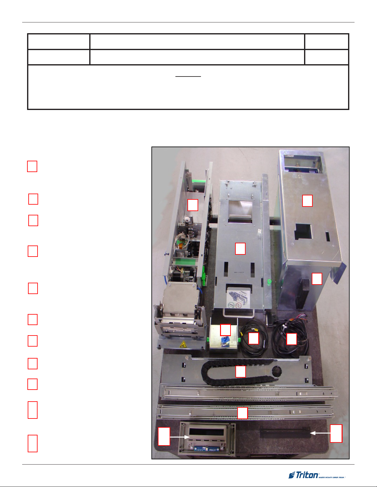
priMary EDU Kit part iDEntiFiCation
Depository
1
Depository w/o Envelope Presenter
2
EDU Bin Mounting Bracket Assembly
3
4
5
6
7
Part of the EDU Assembly
EDU Comms and Power Cable
with Envelope Presenter
(
09002-03002
or
(
09002-03001
EDU Tray Assembly
(09002-03009)
(09200-03006)
Depository Catch Bin
(03011-01217)
(09200-03010)
Depository Bin Lock Pawl
(03011-01344)
Part of the EDU Assembly
(09200-03010)
UCV4 Ground Wire Cable
(09200-03006)
(09120-00740)
)
)
1
2
5
6
3
4
7
8
9
10
11
UCV Vertical Assembly
(09200-03008)
LH Slide
(03082-00022)
EDU Bezel
(09200-03007)
Includes Rain Guard
Rain Guard
( 03011-01337)
Part of the EDU Bezel
(09200-030070)
10
8
9
11
5
Page 6

MoDEl Ft7000 EDU assEMbly FiElD installation GUiDE
Installation of the EDU Depository Bin and Mounting Bracket Assembly
1. Refer to the Figure below. Mount two (2) white cable hangers (the openings facing outward) to
the bottom of the I/O Bay with two (2) 4 mm x 12 mm pan head screws.
i/o bay
Cable Hangers
2. Refer to the Figures below. Pre-mount three (3) #8-32 x 3/4” screws to the top of the Depository
Bin Mounting Bracket (with the envelope chute to the front, the screws should be mounted at the
forward left/right corners and the back left corner) so they match up with the “slotted” mounting
holes in the bottom of the I/O Bay. Do not tighten the screws!
3. Set the Depository Bin Mounting Bracket in the EDU Depository Bay. Feed the Bin Present
Switch cable UP through the opening to the I/O Bay.
(lowEr)
i/o bay
DEpository bin
MoUntinG braCKEt
(lowEr)
(3) Pre-mounted
“positioning” screws
DEpository bin
MoUntinG braCKEt
Bin Present
Switch Cable
EDU DEpository bay
4. Refer to the Figures below. Hold the Depository Bin Mounting Bracket up against the top of the
Depository Bay so the three (3)” pre-mounted “positioning” screws protrude through the slotted
mounting holes in the bottom of the I/O Bay. Slide the bracket toward the rear of the cabinet until
the hole for the “xed” mounting screw (back right corner) matches up with the corresponding
mounting hole in the bottom of the I/O Bay. Secure the Depository Bin Mounting Bracket to the
bottom of the I/O Bay with an #8-32 x 3/4” screw and tighten down the other three (3) mounting
screws.
Bin Present
Switch Cable
DEpository bin
MoUntinG braCKEt
Bin Present
Switch Cable
“Fixed” Depository
EDU DEpository
bay
(3) Pre-mounted “positioning”
screws on the Depository Bin
Mounting Bracket
Bin Mounting Bracket
screw
i/o bay
(lowEr)
6
Page 7

MoDEl Ft7000 EDU assEMbly FiElD installation GUiDE
5. Slide the EDU Depository Bin into the EDU Depository Bin Mounting Bracket.
Installation of the EDU Comms/Power and UCV4 Ground Cables (Cabinet Side)
1. Refer to the Figure below. Remove the Rear Service Panel (RSP) cables from the white cable
hanger (directly below the approximate center of the main GPIO PCB). Loosen and rotate the
cable hanger 180 degrees (so the opening in the cable hanger is to the rear of the cabinet).
Tighten the mounting screw for the cable hanger.
2. Press the EDU Comms/Power cable into the white cable hanger and plug it into the main GPIO
PCB (J4).
3. Locate the four (4) grounding studs to the right of the cable hanger used for the EDU Comms/
Power cable. Press the UCV4 Ground cable into the white cable hanger below the grounding
studs. Connect the UCV4 Ground cable to an open grounding stud with an #8 x 32” nut.
Gpio pCb
EDU Power/
Comms Cable
RSP
Cables
Cable Hangers
UCV4 Ground
Cable
i/o bay
(UppEr)
Installation of the EDU Tray and Mounting Hardware
UCV Vertical Assembly (includes the Right Hand Slide and E-Chain):
1. Refer to the Figures below. Lay the UCV Vertical Assembly on the bottom of the I/O Bay (upside
down with the micro-switch to the front of the cabinet.
2. There are two cables hanging down at the front right corner of the I/O Bay. Select the cable
marked “ UCV4” and plug it into the micro-switch on the UCV Vertical Assembly.
UCV4 connection to the
UCV Vertical Assembly
UCv vErtiCal
assEMbly
i/o bay
(lowEr)
7
Page 8

MoDEl Ft7000 EDU assEMbly FiElD installation GUiDE
3. Refer to the Figure below. Line up the L-shaped hooks on the UCV Vertical Assembly with the
corresponding openings in two (2) inside vertical I/O mounting rails (trays) on the right side of the
cabinet. The UCV Vertical Assembly should be positioned at vertical location “32” (the number
“31” should be showing just above the mounted location of the UCV Vertical Assembly).
4. Slip the L-shaped hooks through the openings and press DOWN until the two (2) “spring loaded
pins” lock into place.
5. Push the EDU Comms/Power, UCV4 Ground, and EU Bin Present Switch cables through the
opening in the UCV Vertical Assembly (from the back side - see insert).
Vertical position
Vertical mounting rails
(I/O trays)
Spring loaded
pins
UCv vErtiCal
assEMbly
i/o bay
(lowEr)
“31” (showing)
Left Hand Slide Rail Assembly:
1. Refer to the Figures below. Line up the left hand slide rail assembly with corresponding mounting points in the two (2) outside vertical I/O mounting rails (trays) on the left side of the cabinet. It
should be positioned at vertical location “32” (the lowest mounting point on the rails - the number
“31” should be showing just above the mounted location of the Left Slide Rail Assembly).
2. Slip the hooked tabs on the outside edge of the slide rail through the opening in the two (2) outside vertical I/O mounting rails (trays) and press DOWN and IN until it locks into place and the
raised edge on the front tab “snaps” into place.
vErtiCal MoUntinG
rails (i/o trays)
Vertical position
“31” (showing)
lEFt siDE rail assEMbly MoUntED (oUtsiDE viEw)
lEFt siDE rail assEMbly MoUntED (insiDE viEw)
lEFt sliDE
rail assEMbly
i/o bay
(lowEr)
lEFt sliDE rail
assEMbly
UCv vErtiCal
assEMbly
8
Page 9

MoDEl Ft7000 EDU assEMbly FiElD installation GUiDE
EDU Tray Assembly:
1. Refer to the Figure below. Fully extend the left and right hand slide rails (the right hand slide rail
is part of the UCV Vertical Assembly).
sliDE rails ExtEnDED w/o EDU tray
Horizontal slide
mounting slot
Vertical slide
mounting slot
2. Refer to the Figure below. Place the EDU Tray Assembly between the slide rails so the horizontal (front) and vertical (rear) mounting tabs on the tray are just behind the corresponding slots
on the slide rails.
3. Fit the (front) horizontal mounting tabs on the tray into the corresponding slots on the slide rails.
Pull the tray backward until the mounting tabs are fully engaged in the slots.
4. Fit the (rear) vertical mounting tabs on the tray into the corresponding slots on the slide rails.
Push the tray DOWNWARD until the mounting tabs are full engaged in the slots.
EDU tray MoUntED on sliDE rails
EDU tray mounted
in the horizontal slot
EDU tray mounted
in the vertical slot
5. Secure the EDU Tray Assembly to the left and right slide rails with two (2) #8/32 x 3/8” screws.
9
Page 10

MoDEl Ft7000 EDU assEMbly FiElD installation GUiDE
6. Refer to the Figures below. Secure the E-Chain (cable bundle track) to the front right corner of
the tray with two (2) #4-40 x 1/4” stainless steel screws.
UCv vErtiCal
assEMbly
i/o bay
(lowEr)
E-CHain
(CablE traCK)
E-Chain Connection to
the EDU Tray
EDU
tray
7. Refer to the Figures below. Press the EDU Comms/Power, UCV4 Ground, and the EDU Bin
Present Switch cables into the E-Chain (cable track).
8. Ty wrap the UCV4 Ground and EDU Bin Present Switch cables (together) to a hanger at the
entrance to the of the E-Chain.
9. Ty wrap the EDU Comms/Power cable (individually) to a hanger at the entrance to the of the
E-Chain.
UCv vErtiCal
assEMbly
EDU Comms/
Power Cable
EDU Bin Present
Switch Cable
UCV Ground
Cable
Cable Ty
Hangers
10. Refer to the following Figures. Ty wrap the UCV4 Ground and EDU Bin Present Switch cables
(together) to a hanger at the output of the E-Chain. Secure the UCV4 Ground cable to the stud
at the front right corner of the EDU Tray (just past where it comes out of the E-Chain) with a #832” nut.
11. Ty wrap the EDU Comms/Power cable (individually) to a hanger at the output of the E-Chain.
Press the EDU Comms/Power cable into the two (2) white cable clips along the right side of the
tray.
10
Page 11

MoDEl Ft7000 EDU assEMbly FiElD installation GUiDE
E-CHain
(CablE traCK)
UCv vErtiCal
assEMbly
i/o bay
(lowEr)
EDU Bin Present
Switch Cable
EDU
tray
EDU Comms/Power
Cable and Clips
UCV Ground
Cable Connection
Cable Ty
Hangers
Installation of the EDU Mechanism on the Mounting Tray
MoUntinG tHE EDU MECHanisM
1. Set the EDU Mechanism on the tray (along the left side of the tray). This will help facilitate the
connection of the cables.
2. Refer to the Figures below. Plug the EDU Bin Present Switch cable (at the output of the E-Chain)
into the “Bins” connector at the EDU (at the forward edge of the EDU Driver PCB). The “Bins”
connector (on the EDU side) should be marked with a WHITE dot and the cable is labeled as
“Bins”).
3. The EDU Comms/Power cable is a bundle of two (2) cables (Power and Comms). Plug the
Power cable into the top connector on the rear edge of the EDU Driver PCB (If there is an extension cable plugged in at this location, plug the Power cable into the extension cable). Plug
the Comms cable into the connector that is third (3rd) from the top on the rear edge of the EDU
Driver PCB.
ConnECtinG tHE bin switCH CablE to tHE EDU
BINS
Connection
edu
tray
Extension cable
for Power cable
ConnECtinG tHE CoMMs/powEr CablE to tHE EDU
EDU
edu
tray
Power connection
at EDU
EDU Mechanism
Driver PCB
Comms connection
at EDU
4. Ty wrap any excess of the EDU Comms/Power cable to the inside right edge of the tray at the
provided tie down point (right side of the tray, neat the rear of the EDU Mechanism).
11
Page 12

MoDEl Ft7000 EDU assEMbly FiElD installation GUiDE
5. Refer to the Figures below. Center the EDU mechanism on the tray, between the metal left and
right locator guides (raised left and right edges, set at the width of the EDU Mechanism, and
located approximately 6” in from the rear edge of the EDU Tray).
6. Slide the EDU Mechanism to the rear of the tray, making sure the front pads on the bottom, left
and right front edge of the mechanism slide under the retainer hooks on the tray.
Retention clips at the front
edge (left/right sides) of
the EDU Tray
Retention pads at the front
edge (left/right sides) of
the EDU Mechanism
EDU tray
7. Refer to the Figure below. Make sure the mounting holes at the rear of the mechanism line up
with the corresponding holes in the tray. After the installation of the front Bezel, adjust the position of the EDU Mechanism. With the front panel closed, and the EDU tray pushed forward and
latched, push the EDU mechanism forward gently until the two (2) rubber bump stops are snug
against the back of the Bezel, or the slots are fully forward. Secure the EDU with two (2) #8-32
x 3/8” screws.
EDU MECHanisM
Locator guides (left/
right sides) on the
EDU Tray
installation oF tHE DEpsitory loCK pawl
1. Refer to the Figures below. Mount the Depository Lock Pawl at the rear of the EDU Mechanism
(over the two (2) screws that secure the EDU Mechanism to the tray). Make sure the pawls t
down in the openings in the top of the EDU, and that the Green, spring loaded latches engage
the EDU on the sides. Mount a metal guide sleeve (through the slot on the Lock Pawl) on the left
and rights sides of the lock box (at the rear of the EDU Mechanism) with an #8-32 x 3/8” screw.
Use the key provided to secure the mechanism.
Lock Pawl Key
EDU MECHanisM
loCK pawl
EDU tray
2. DO NOT leave the Depository Lock Pawl mechanism off. It is an integral part of the overall EDU
and FT7000 security features.
Guide Sleeve
Spring loaded
Lock Pawl latch
12
Page 13

MoDEl Ft7000 EDU assEMbly FiElD installation GUiDE
Installation of the EDU Bezel
rEMoval oF tHE baCKEr platE anD ExistinG bEzEls
1. Loosen the 4 (four) screws on the 5” Backer plate. Do not
remove these screws at this time.
2. Lift the 5 in. Backer plate off of the screws and remove it
from the 4 (four) mounting screws.
3. Loosen the 4 (four) screws on the 3” Backer plate. Do not
remove these screws at this time.
4. Lift the 3 in. Backer plate off of the screws and remove it
from the 4 (four) mounting screws.
Mounting
Screws
Mounting
Screws
5in
Backer
Plate
3in
Backer
Plate
5. Remove the 2 (two) screws retaining the 1” Bezel. Retain
these screws.
6. Remove the 4 (four) mounting screws that were retaining
the 3” Backer plate, and remove the existing 3 in. Bezel.
Retain these screws.
7. Remove the 4 (four) mounting screws that were retaining the 5” Backer plate, and remove the existing 5“ Bezel.
Retain these screws.
8. Remove the EDU LED cable from the lowest Cable clamp.
Note: there may be more than one cable available, the
power cable for the EDU Bezel is the longest.
Mounting
Screws
Mounting
Screws
5” Bezel
3” Bezel
1” Bezel
Cable
Clamp
13
Page 14

MoDEl Ft7000 EDU assEMbly FiElD installation GUiDE
installation oF tHE baCKinG platEs anD bEzEls
1. Mount the EDU Bezel at the lowest position possible,
with the LED assembly at the top. Secure it with 2 (two)
screws in the lowest position.
2. Mount the rain guard to the top of the EDU Bezel with 2
(two) screws.
3. Remount the 5 in. Bezel with 4 (four) screws, but DO NOT
tighten. Ensure the Bezel is interlocked with the printer
Bezel above and the EDU Bezel below.
4. Press t the cable guide into the hole available in the rain
guard.
5. Plug the EDU LED power cable into the EDU LCD printed
circuit board on the EDU Bezel.
7. Lay the EDU LED power cable in the cable guide and then
press t the cable guide into place to secure the power
cable.
8. Reinstall the 5 in. Backer plate over the 4 (four) mounting screws. Push the Backer plate down until it is snug
against the EDU Bezel rain guard, and tighten the 4 (four)
Backer plate screws.
Cable
Guide
5 inch
Backer Plate
Reinstalled
5 in
Bezel
Rain
Guard
EDU
Bezel
9. Front view of completed EDU Bezel installation.
14
 Loading...