

Page 1

MODEL RL/FT5000
XP
PC-BASED ATMS
USER MANUAL
VERSION 2.0
TDN 07102-00057B Oct 23 2009
CORPORATE HEADQUARTERS:
21405 B Street
Long Beach, MS 39560
Phone: (228) 575-3188
Fax: (228) 575-3200
COPYRIGHT NOTICE
© 2008 Delaware Capital Formation, Inc. All Rights Reserved. T riton Systems
of Delaware, Inc. is an operating company of Dover Electronics, Inc., a subsidiary of Dover Corporation (NYSE-DOV). DOVER, the DOVER logo and the
Dover family of marks and TRITON, the TRITON logo and the Triton family
of marks are registered trademarks of Delaware Capital Formation, Inc., a wholly
owned subsidiary of Dover Corporation.
Page 2

MODEL RL/FT5000XP USER MANUAL
DISCLAIMER
The manufacturer of the Automated T eller Machine (ATM) product(s) described
herein makes no representations or warranties, either expressed or implied, by or
with respect to anything in this manual, and shall not be liable for any implied
warranties of fitness for a particular purpose or for any indirect, special, or
consequential damages. Information in this document is subject to change
without notice and does not represent a commitment on the part of the
manufacturer.
** CAUTION **
Changes or modifications not expressly approved by Triton
Systems could void the regulatory compliance approval
and the warranty. Use of this pr oduct in a manner other
than those described in this manual may result in personal
injury!
FCC COMPLIANCE
(US units with modems)
Statement of Compliance: This equipment complies with Part 68 of the FCC
rules. Located in the control area of the ATM is the product label. This label
lists the FCC registration number and ringer equivalence number of the unit. If
requested, this information must be provided to the telephone company. USOC/
FIC Codes: When ordering service from the telephone company for the XPseries ATMs, the following information should be supplied:
Universal Service Order Code (USOC): RJ-11C
The Facility Interface Code (FIC): 02LS2
Plug and Jack: The plug and jack used to connect this equipment to premise
wiring and telephone network must comply with the applicable FCC Part 68 rules
and requirements adopted by ACTA. A compliant telephone cord and modular
plug is provided with this product. The telephone cord is designed to be
connected to a compatible modular jack that is also compliant.
Ringer Equivalent Number (REN): The REN is used to determine the number of
the devices that may be connected to a telephone line. Excessive RENs on a
telephone line may result in the devices not ringing in response to an incoming
call. In most but not all areas, the sum of the RENs should not exceed five (5). T o
be certain of the number devices that may be connected to a line, as determined
by the local RENs, contact the local telephone company.
ii
Page 3

MODEL RL/FT5000
Harm to the Network: If the XP-series ATMs cause harm to the telephone
network, the telephone company will notify the customer that a temporary
discontinuation of service may be required. If advanced notice is not possible,
the telephone company will notify the customer as soon as possible. You will be
advised of your right to file a complaint with the FCC if you believe it’s necessary .
Notification of Changes in Telephone Company Equipment: The telephone
company may make changes in its facilities, equipment, operations, or procedures
that could affect the operation of the equipment. If this happens, the telephone
company will provide advanced notice in order for you to make necessary
modifications to maintain uninterrupted service.
Repairs and Returns: If telecom compatibility trouble is experienced with the
XP- series ATMs, you may contact for repairs and warranty information: T riton
at 1-228-868-1317
Triton Systems of Delaware, Inc.
522 East Railroad Street
Long Beach, MS 39560
If the equipment is causing harm to the network, the telephone company may
request that you disconnect the equipment until the problem is resolved. Repairs
should be made only by qualified factory representatives.
XP
USER MANUAL
Party Lines: The XP-series ATMs must not be used on party lines.
Alarm Equipment: The XP-series ATMs should have their own dedicated phone
line. Do not install the ATMs on the same line as alarm equipment.
Electrical Safety Advisory: Telephone companies report that electrical surges,
typically lightening transients, are very destructive to customer equipment
connected to AC power sources. This has been identified as a major nationwide
problem. A commercially available, power surge suppressor, is recommended
for use with the XP-series ATMs to minimize damage in the event of an electrical
surge.
CANADIAN IC COMPLIANCE
Notice:
The Industry Canada label identifies certified equipment. This certification
means that the equipment meets telecommunications network protective, operational, and safety requirements as prescribed in the appropriate terminal equipment technical requirements document(s). The department does not guarantee
the equipment will operate to the user’s satisfaction.
iii
Page 4

MODEL RL/FT5000XP USER MANUAL
Before installing this equipment, users should ensure that it is permissible to be
connected to the facilities of the local telecommunications company. The equipment must also be installed using an acceptable method of connection. The
customer should be aware that compliance with the above conditions may not
prevent degradation of service in some situations.
Repairs to certified equipment should be coordinated by a representative designated by the supplier. Any repairs or alterations made by the user to this
equipment or equipment malfunctions may give the telecommunications company cause to request the user to disconnect the equipment.
Users should ensure for their own protection that the electrical ground connections of the power utility, telephone lines and internal metallic water pipe system, if present, are connected together. This precaution may be particularly
important in rural areas. Caution: Users should not attempt to make such connections themselves, but should contact the appropriate electric inspection
authority or electrician, as appropriate.
NOTICE:
The Ringer Equivalence Number (REN) assigned to each terminal device provides an indication of the maximum number of terminals allowed to be connected
to a telephone interface. The termination on an interface may consist of any
combination of devices subject only to the requirement that the sum of the
Ringer Equivalence Numbers of all the devices does not exceed 5.
AVIS:
L ’étiquette d’Industrie Canada identific le matériel homologué. Cette étiquette
certifie que le matériel est conforme aux normes de protection, d’exploitation et
de sécurité des réseaux de télécommunications, comme le prescrivent les documents concernant les exigences techniques relatives au matériel terminal. Le
Ministère n’assure toutefois pas que le matériel fonctionnera à la satisfaction de
l’utilisateur.
Avant d’installer ce matériel, l’utilisateur doit s’assurer qu’il est permis de le
raccorder aux installations de 1’entreprise locale de télécommunication. Le
matériel doit également être installé en suivant une méthode acceptée de
raccordement. L ’abonné ne doit pas oublier qu’il est possible que la comformité
aux conditions énoncées cidessus n’empêche pas la dégradation du service
dans certaines situations.
iv
Page 5

MODEL RL/FT5000
Les réparations de matériel homologué doivent être coordonnées par un
représentant désigné par le fournisseur. L’entreprise de télécommunications
peut demander à I’utilisateur de débrancher un appareil à la suite de réparations
ou de modifications effectuées par l’utilisateur ou à cause de mauvais
fonctionnement.
Pour sa propre protection, l’utilisateur doit s’assurer que tous les fils de mise à
la terre de la source d’énergie électrique, des lignes téléphoniques et des
canalisations d’eau métalliques, s’fl y en a, sont raccordés ensemble. Cette
précaution est particulièrement importante dans les régions rurales.
Avertissement: L’utilisateur ne doit pas tenter de faire ces raccordements luimême; il doit avoir recours à an service d’inspection des installations électriques,
ou à un électricien, selon le cas.
XP
USER MANUAL
AVIS:
L’indice d’équivalence de la sonnerie (IES) assigné à chaque dispositif terminal
indique le nombre maximal de terminaux qui peuvent étre raccordés à une interface.
La terminaison d’une interface téléphonique peut consister en une combinaison de
quelques dispositifs, à la seule condition que la somme d’indices d’équivalence de
la sonnerie de tous les dispositifs n’exède pas 5.
UNITED KINGDOM
This equipment has been approved in accordance with Council Decision 98/
482/EC for pan-European single terminal connection to the Public Switched
Telephone Network (PSTN). However, due to differences between the individual PSTNs provided in the different countries, the approval does not, of
itself, give unconditional assurance of successful operation on every PSTN
network termination point. In the event of problems, contact your equipment
supplier in the first instance. This unit uses only Dual-Tone Multi-Frequency
(DTMF) address signaling.
EMISSIONS (EMI)
(US Requirements)
This device complies with Part 15 of the FCC rules. Operation is subject to the
following two (2) conditions:
1) This device may not cause harmful interference.
2) This device must accept any interference received, including interference
that may cause undesired operation.
v
Page 6

MODEL RL/FT5000XP USER MANUAL
NOTE:
This equipment has been tested and found to comply with the limits for a Class
A digital device pursuant to Part 15 of FCC rules. These limits are designed to
provide reasonable protection against harmful interference when the equipment
is operated in a commercial environment. This equipment generates, uses, and
can radiate radio frequency energy and, if not installed and used in accordance
with the instruction manual, may cause harmful interference to radio
communications. Operation of this equipment in a residential area is likely to
cause harmful interference in which case the user will be required to correct the
interference at his own expense. Changes or modifications to this unit not
expressly approved by the party responsible for compliance could void the
user’s authority to operate the equipment.
CANADIAN REQUIREMENTS
This digital apparatus does not exceed the Class A limits for radio noise emissions
from digital apparatus set in the Radio Interference Regulations of the Canadian
Department of Communications. This Class A digital apparatus complies with
Canadian ICES-003.
Le present appareil numerique n’emet pas de bruits radioelectriques depassant
les limites applicables aux appareils numeriques de la Class A prescrites dans le
Reglement sur le brouillage radioelectrique edicte par le ministere des
Communications du Canada. Cet appareil numerique de la classe A est conforme
a la norme NMB-003 Canada.
UK REQUIREMENTS
Warning:
This is a Class A product. In a domestic environment, this product may cause
radio interference in which case the user may be required to take adequate
measures.
vi
Page 7

MODEL RL/FT5000
XP
USER MANUAL
NOTICES
Copyright © Delaware Capital Formation, Inc., 2006.
ALL RIGHTS RESERVED
This publication is protected by copyright and all rights are reserved. No part of
it may be reproduced or transmitted by any means or in any form, without prior
consent in writing from Triton Systems of Delaware, Inc.
The information in this publication has been carefully checked and is believed
to be accurate. However, Triton Systems of Delaware, Inc. assumes no responsibility for any inaccuracies, errors, or omissions that may be contained in this
document. In no event will Triton Systems of Delaware, Inc. be liable for direct,
indirect, special, incidental, or consequential damages resulting from any defect
or omission in this manual, even if advised of the possibility of such damages.
In the interest of continued product development, Triton Systems of Delaware,
Inc. reserves the right to make improvements in its documentation and the
products it describes at any time, without notice or obligation.
TRADEMARK ACKNOWLEDGEMENTS
Microsoft Windows is a registered trademark of Microsoft Corporation in the
United States and/or other countries. Triton Connect and Prism are trademarks
of Triton Systems of Delaware, Inc. CashWorks is a trademark of CashW orks,Inc.
PaySpot is a trademark of Euronet Worldwide. Western Union is a registered
trademark of Western Union Holdings, Inc. Intel is a registered trademark of
Intel Corporation.
vii
Page 8

MODEL RL/FT5000XP USER MANUAL
WARRANTY STA TEMENT
Manufacturer warrants that the products delivered to a distributor will perform
in accordance with the Manufacturer’s published specifications for thirteen
months from date of shipment in Long Beach, MS.
Manufacturer’s warranty shall not apply to any damage resulting from abuse,
negligence, accident, or to any loss or damage to the products while in transit.
Written notice and explanation of circumstances surrounding any claims that
the goods have proved defective in material or workmanship shall be given
promptly from the distributor to the manufacturer. No claim may be made, or
action brought, by or through a distributor after the expiration of 14 months
following any alleged breach of warranty.
Distributor’s sole and exclusive remedy in the event of defect is expressly
limited to the replacement or correction of such defective parts by manufacturer at its election and sole expense, except there shall be no obligation to
replace or repair items which, by their nature, are expendable. If Manufacturer
is unable to replace or repair the defective parts, Manufacturer shall refund to
Distributor that portion of the purchase price allocable pays to such goods.
No representation or other affirmation of fact not set forth herein, including but
not limited to statements regarding capacity, suitability for use, or performance
of the goods, shall be or be deemed to be a warranty or representation by
Manufacturer for any purpose, nor give rise to any liability or obligation of
Manufacturer whatever.
Except as specifically provided in this document, there are no other warranties
expressed or implied including, but not limited to, any implied warranties or
merchantability or fitness for a particular purchase.
LIMITATION OF LIABILITY
In no event shall manufacturer be liable for loss of profits or incidental, indirect, special, consequential or other similar damages arising out of any breach
of this contract or obligations under this contract.
DEFENSE OF INFRINGEMENT CLAIMS
If notified promptly in writing of any action (and all prior claims relating to such
action) brought against the Distributor based on a claim that Distributor’s use of
the goods infringes a patent or other intellectual property right, and if given
access by Distributor to any information distributor has regarding such alleged
infringement, Manufacturer agrees to defend Distributor in such action at its
expense and will pay any costs or damages finally awarded against Distributor
viii
Page 9

MODEL RL/FT5000
in any such action, provided the Manufacturer shall have had sole control of the
defense of any such action and all negotiations for its settlement or compromise.
In the event that a final injunction shall be obtained against the Distributor’s use
of the goods or any of their parts by reason of infringement of a patent or other
intellectual property right or if in Manufacturer’s opinion the goods are likely to
become the subject of a claim of infringement of a patent or other intellectual
property right, Manufacturer will, at its option and at its expense, either procure
for the Distributor the right to continue using the goods, replace or modify the
same so they become non-infringing or grant the Distributor a credit for such
goods as depreciated and accept their return. The depreciation shall be an equal
amount per year over the lifetime of the goods as established by Manufacturer.
Manufacturer shall not have any liability to the Distributor under any provision
of this clause if any infringement, or claim thereof, is based upon: (i) the use of
the goods in combination with other goods or devices which are not made by
Manufacturer; (ii) the use of the goods in practicing any process; (iii) the furnishing to the Distributor of any information, date, service, or applications assistance; or (iv) the use of the goods with modifications made by the Distributor.
The Distributor shall hold Manufacturer harmless against any expense, judgment or loss for infringement of any patent or other intellectual property right
which results from Manufacturer’s compliance with the Distributor’s designs,
specifications or instructions. No costs or expenses shall be incurred for the
account of Manufacturer without the written consent of Manufacturer. The
foregoing states the entire liability of manufacturer with respect to infringement of patents or other intellectual property right by the goods or any part
thereof, or by their operation.
XP
USER MANUAL
INTERPRETATION AND OTHER PAROLE EVIDENCE
This writing is intended by the parties as final expression of their agreement and
is intended also as a complete and exclusive statement of the terms of their
agreement. No course of prior dealing between the parties and no usage of the
trade shall be relevant to supplement or explain any term used in these terms and
conditions. Acceptance or acquiescence in a course of performance rendered
under these terms and conditions shall not be relevant to determine the meaning
of these terms and conditions even though the accepting or acquiescing party
has knowledge of the performance and opportunity for objection. Whenever a
term defined by the Uniform Commercial Code, as adopted in Mississippi, is
used in these terms and conditions, the definition contained in the code is to
control.
ix
Page 10

MODEL RL/FT5000XP USER MANUAL
MODIFICATIONS
These terms and conditions can be modified or rescinded only by writing signed
by both the parties or their duly authorized agents.
WAIVER INEFFECTIVE
No claim or right arising out of or relating to a breach of these terms and conditions can be discharged in whole or in part by a waiver or renunciation of the
claim or right unless the waiver or renunciation is supported by consideration
and is in writing signed by the aggrieved party. Waiver by either Manufacturer
or Distributor of a breach by the other of any provision of these terms and
conditions shall not be deemed a waiver of future compliance therewith, and
such provisions shall remain in full force and effect.
STATUTE OF LIMITATIONS
Any action by the Distributor or Manufacturer for breach of these terms and
conditions must be commenced within one (1) year after the cause of action has
accrued.
APPLICABLE LAW
These terms and conditions shall be governed by and construed in accordance
with the provisions of the Uniform Commercial Code as adopted by the State of
Mississippi.
BANKRUPTCY
In the event of any proceedings, voluntary or involuntary, in bankruptcy or
insolvency by or against Distributor, or in the event of the appointment, with or
without the Distributor’s consent, of an assignee for the benefit of creditors or
of a receiver or of a liquidator, then Manufacturer shall be entitled to cancel any
unfilled part of these terms and conditions without any liability whatsoever.
PARTS ONLY LIMITED MANUFACTURER’S WARRANTY
Triton Systems of Delaware, Inc. warrants the components of each XP-series
ATM, excluding software and related documentation, against any defect in
materials and/or workmanship for a period of 13 months from the shipping date.
If a component fails due to defects in materials and/or workmanship within the
warranty period, Triton will furnish a new or refurbished component, at its discretion. Triton shall not be responsible for labor or other costs associated with
installing the components and the failed component shall be returned to Triton
at the purchaser’s expense. T riton shall not be responsible for misuse or abuse
of a unit and any attempts to remove or deface the serial number or date code on
a unit or any component thereof, or any attempt to repair a unit or to repair or
replace any component by anyone other than a service technician authorized by
Triton shall void this warranty.
x
Page 11

MODEL RL/FT5000
Limited Warranty covers normal use. T riton does not warrant or cover
damage:
• occurring during shipment of the equipment or components from or to
Triton’ s facilities;
• caused by accident, impact with other objects, dropping, falls, spilled liquids, or immersion in liquids;
• caused by a disaster such as fire, flood, wind, earthquake, lightning, or
other acts of God;
• caused by failure to provide a suitable installation environment for the
equipment, including but not limited to, faulty wiring in the building in
which the equipment is installed, installation in a facility with uncontrolled
environmental conditions, failure to provide a dedicated electrical circuit on
which the equipment operates, and/or lack of proper earth grounding for
the equipment;
• caused by the use of the equipment for purposes other than those for
which it was designed;
• resulting from improper maintenance;
• caused by any other abuse, misuse, mishandling, or misapplication.
Under no circumstances shall Triton or its suppliers be liable for any special,
incidental, or consequential damages based upon breach of warranty, breach of
contract, negligence, strict liability, or any other legal theory. Such damages
include, but are not limited to, loss of profits, loss of revenue, loss of data, loss
of use of the equipment or any associated equipment, cost of capital, cost of
substitute or replacement equipment, facilities or services, downtime, purchaser’s
time, the claims of third parties, including customers, and injury to property.
XP
USER MANUAL
DISCLAIMER OF WARRANTIES
The warranty stated above is the only warranty applicable to this product. All
other warranties, expressed or implied (including all implied warranties of merchantability or fitness for a particular purpose or quality of service), are hereby
disclaimed. No oral or written information, or advice given by Triton, its agents
or employees shall create a warranty or in any way increase the scope of this
warranty.
SHIPPING DAMAGE
All equipment is shipped Free On Board (FOB), Triton’ s facilities. The organization or individual who has purchased the equipment assumes responsibility for
the equipment once it leaves Triton’s facilities.
Should your equipment be damaged in the process of shipment or delivery to
your place of destination, we recommend the following course of action:
xi
Page 12

MODEL RL/FT5000XP USER MANUAL
• If possible, call the shipping company before the driver leaves your delivery site. Make note of the damage on the “receipt of delivery” paperwork.
If this is not possible, call them as soon as possible to report the damage.
• T ake photographs of the damaged packaging prior to opening the boxes. If
this is not possible, make note of key points, such as whether the equipment is on a pallet, if the banding is intact, how the boxes are damaged, etc.
Keep all of the packaging for inspection by the shipping company.
• If you unpack the equipment, take photographs of the damaged equipment.
If this is not possible, make note of the damages.
• You must file a claim with the shipper for shipping damages immediately
after reporting the damages.
Should you specify the carrier, we recommend that you explore with this chosen
carrier the policies and procedures regarding shipping damage claims prior to
selecting them as your preferred carrier.
If the equipment receives structural damage and is in an un-installable condition, Triton will work with you to arrange for a replacement unit to be shipped as
soon as possible. The purchaser will be billed for the replacement unit. T riton’s
repair technicians will repair the damaged unit after it is returned to our facilities.
W e will credit the purchaser’s account for the full purchase price of the damaged
unit, minus the cost of returning the unit to “like new” condition. Under no
circumstances does Triton authorize anyone to complete structural damage
repairs in the field. Therefore, we will not ship primary structural parts, such as
a cabinet head or main cabinet body for repair in the field.
AUTHORIZED INSTALLATION AND SERVICE PROVIDERS
Triton utilizes several nationwide and regional authorized third party maintenance providers. Triton recommends all ATMs be installed and serviced by
service technicians certified by Triton. This includes authorized third party
service technicians and technicians who have been factory trained by Triton to
service ATM equipment. Installation or repairs attempted by unauthorized service technicians may void the warranty or warranty claims denied on the product.
Please contact Triton’ s T echnical Services department at (800) 259-6672 for a list
of our third party service providers and/or to obtain information on the requirements and procedures for becoming a certified Triton service technician.
xii
Page 13

MODEL RL/FT5000
XP
USER MANUAL
TRITON’S TECHNICAL SERVICES DEPARTMENT
The primary purpose of the Technical Services department is to provide assistance to customers in the operation, trouble shooting, and repair of equipment
manufactured by Triton. A toll-free phone number (1-800-259-6672) is provided
for convenience. The Technical Services department operates to serve our
customers. The staff is trained to follow our policies and procedures to ensure
fair and uniform treatment of all our customers.
AUTOMATED VOICE MAIL SYSTEM
Our goal is to have a ‘live’ person answer 100% of all incoming calls (during
regular support hours). On occasion, however, call loads may exceed the capacity of the staff. When this occurs, an automated voice mail system will answer
the call, indicate to the caller that all Technical Support specialists are busy
assisting others, and ask the caller to leave detailed information about the nature of the call.
Should it become necessary to leave a voice mail message, the caller should
state:
• their name,
• the organization for which they work,
• the serial number of the equipment they are calling about,
• detailed description of the problem that they are experiencing, and
• phone number where they can be reached, including area code.
As Technical Support specialists become available, they check for voice mail
messages and return calls in the order in which they were received. By providing the information requested in the voice mail, the technician can be prepared
when your call is returned. Triton asks you to be patient if you must leave voice
mail and assures you that your call is important to us and that we will respond
promptly .
CALLS FOR SERVICE OR REPAIR
Calls for service or repair will be accepted from authorized service technicians
only. End users must contact either the sales organization that placed the
equipment or an authorized third party service organization to obtain service.
The sections that follow describe the policies and procedures that relate to the
repair and replacement of malfunctioning equipment.
xiii
Page 14

MODEL RL/FT5000XP USER MANUAL
QUESTIONS ON OPERATION OF EQUIPMENT
Technical support is available to owners of Triton equipment and to qualified
service personnel. When calling for help with the configuration or operation of
a Triton product, the caller must provide either positive identification as a service technician or the serial number of a Triton terminal. Technical support is
provided during normal business hours for the life of the product.
When calling for help with an operational problem, please have available information pertaining to the nature of the trouble. This includes the type of equipment, examples of what is or is not happening, and the name of the processor
that supports your terminal.
All questions pertaining to the settlement of accounts, transaction inquiries,
and fund status must be directed to the processor. Triton does not have access
to the information needed to answer questions relating to specific transactions.
CONT ACT INFORMATION
Triton Systems of Delaware, Inc.
522 East Railroad Street
Long Beach, MS 39560
SALES:
1 (800) 367-7191
1 (228) 868-1317
1 (228) 868-0437 (Fax)
SERVICE:
1 (800) 259-6672 (Technical Support)
1 (228) 575-3229 Fax (T echnical Support)
1 (228) 868-0859 Fax (Parts)
xiv
Page 15

MODEL RL/FT5000
XP
USER MANUAL
CONTENTS
SECTION 1 - INTRODUCTION ........................................................1
WHAT’S IN THIS MANUAL ................................................................................2
PC-BASED MODELS .........................................................................................2
CLASS OF SERVICE (BUSINESS-VS-LEVEL 1).......................................................... 2
OPERATING SYSTEM ......................................................................................... 2
FEATURE HIGHLIGHTS ....................................................................................... 4
STANDARD FEATURES ....................................................................................... 5
ACCESS AND TRANSACTION SECURITY ........................................................ 5
MULTIMEDIA INTERFACE (AUDIO/VIDEO).................................................... 6
STORAGE OF FILES .................................................................................... 6
VOICE-ENABLED TRANSACTIONS ................................................................ 6
COMMUNICATIONS .....................................................................................7
ELECTRONIC JOURNAL ............................................................................... 7
TERMINAL SETTLEMENT ............................................................................7
MULTI-LANGUAGE SUPPORT ......................................................................8
MESSAGES ...............................................................................................8
REAR SERVICE PANEL (MODEL FTXP) ........................................................8
SECTION 2 - BASIC OPERATION ................................................... 9
INTRODUCTION ................................................................................................. 10
CONTROL PANEL LAYOUT ................................................................................. 10
KEYPAD OPERATION ........................................................................................ 11
SCREEN FUNCTION KEYS ..................................................................................12
REAR SERVICE PANEL (MODEL FTXP) ............................................................... 13
MENU-BASED OPERATION................................................................................. 14
VOICE-ENABLED TRANSACTIONS ....................................................................... 15
SECTION 3 - REPLENISHING CASSETTES ........................................ 17
INTRODUCTION ................................................................................................. 18
DISPENSING MECHANISM (NMD-100) ............................................................... 18
NOTE CONDITION ............................................................................................. 18
REPLENISHING CASSETTES ................................................................................ 20
REMOVING NOTE CASSETTES ...................................................................... 20
OPENING NOTE CASSETTES ........................................................................ 21
LOADING NOTE CASSETTES ........................................................................ 22
INSTALLING NOTE CASSETTES ..................................................................... 23
REMOVING THE REJECT CASSETTE ...................................................................... 24
OPENING THE REJECT CASSETTE ........................................................................ 24
INSTALLING THE REJECT CASSETTE ..................................................................... 25
VERIFY OPERA TION ..........................................................................................26
xv
Page 16

MODEL RL/FT5000XP USER MANUAL
CONTENTS
SECTION 4 - PREVENT ATIVE MAINTENANCE .................................... 27
INTRODUCTION ................................................................................................. 28
REPLENISHING THE RECEIPT PAPER (MODEL RLXP)............................................ 28
REPLENISHING THE RECEIPT PAPER (MODEL FTXP)............................................ 31
REPLENISHING THE JOURNAL PRINTER (OPTIONAL) .............................................33
CLEANING THE ENCLOSURE .............................................................................. 37
CLEANING THE DISPLAY ................................................................................... 37
CARD READER CLEANING ................................................................................. 37
SECTION 5 - MANAGEMENT FUNCTIONS ....................................... 39
INTRODUCTION ................................................................................................. 40
WHAT IS PRISM 912-EMULATION ........................................................................ 40
XP PRISM SOFTWARE ARCHITECTURE .................................................................42
DISPLAY POWER-UP SEQUENCE ........................................................................ 44
ACCESSING THE MANAGEMENT FUNCTIONS MENU ............................................. 44
SWITCHING SCREENS (MODEL FT
FUNCTION AVAILABILITY .................................................................................. 47
MANAGEMENT REPORTS ................................................................................... 48
TERMINAL SETTLEMENT FUNCTIONS ................................................................49
TERMINAL CLOSE FUNCTIONS ........................................................................... 50
VIEW A TM SETTLEMENT TOTALS ...................................................................... 51
CLEAR A TM SETTLEMENT TOTALS.................................................................... 52
REPLENISH CASSETTE(S) ................................................................................... 53
XP)
................................................................................................................
46
DIAGNOSTICS ................................................................................................. 54
DIAGNOSTIC FUNCTIONS ................................................................................... 56
CASH DISPENSER ............................................................................................. 57
CASH DISPENSER STATUS ........................................................................... 58
PURGE .....................................................................................................59
TEST DISPENSE ......................................................................................... 60
FORCE UNLOCK CASSETTE .........................................................................61
INJECT NEW CASSETTE ID .......................................................................... 6 2
UNLOCK / LOCK ALL CASSETTES ...............................................................63
CARD READER .................................................................................................64
CARD READER STATUS .............................................................................. 65
SCAN CARD .............................................................................................66
TRACK 3 READ / WRITE ............................................................................ 67
RESET ...................................................................................................... 67
PRINTER .......................................................................................................... 68
DEVICE STATUS ......................................................................................... 69
PRINT TEST DATA ...................................................................................... 70
RESET ...................................................................................................... 70
xvi
Page 17

MODEL RL/FT5000
XP
USER MANUAL
CONTENTS
KEYPAD.......................................................................................................... 71
KEYPAD DEVICE STATUS ............................................................................ 72
TEST KEYPAD .......................................................................................... 73
CLEAR TAMPER ........................................................................................ 74
RESET ...................................................................................................... 74
GENERAL I/O DIAGNOSTICS .............................................................................. 75
LED INDICATORS ...................................................................................... 75
HEADPHONE TEST ....................................................................................76
SAFE DOOR TEST ...................................................................................... 76
CABINET DOOR TEST ................................................................................. 77
PRINTER POSITION TEST ............................................................................. 77
PREVIEW SAMPLE VOICE ........................................................................... 77
ELECTRONIC JOURNAL .................................................................................... 78
ELECTRONIC JOURNAL FUNCTIONS ..................................................................... 79
EXPORT UNAUDITED RECORDS ........................................................................... 80
DISPLAY LAST X RECORDS ................................................................................ 81
JOURNAL STATISTICS ......................................................................................... 82
JOURNAL SETTINGS ............................................................................................... 83-84
AUTO EXPORT .......................................................................................... 83
AUTO DELETE .......................................................................................... 83
DELETE INTERVAL (DAYS) .......................................................................... 84
DELETE RECORDS OLDER THAN (DAYS) ..................................................... 84
SAVE SETTINGS / EXIT ................................................................................ 84
PASSWORD MAINTENANCE .............................................................................. 85
PASSWORD MAINTENANCE FUNCTIONS .............................................................. 86
CHANGE USER PASSWORD ................................................................................ 87
CHANGE USER NAME .......................................................................................88
MODIFY USER A CCESS ......................................................................................... 89-91
ADD USER ...................................................................................................... 92
REMOVE USER ................................................................................................. 93
TERMINAL USERS ............................................................................................. 94
USER ACCESS REPORT ...................................................................................... 95
CHANGE USERS PASSWORD .............................................................................. 96
SYSTEM PARAMETERS .....................................................................................97
SYSTEM PARAMETERS FUNCTIONS ......................................................................98
GENERAL SETTINGS .......................................................................................... 99
TIME ZONE / DATA / TIME ......................................................................... 99
SELECT SCREEN FILE ....................................................................................... 100
SHUTDOWN / RESTART TERMINAL ...................................................................... 101
PERFORM SOFTWARE UPDATES .......................................................................... 102
xvii
Page 18

MODEL RL/FT5000XP USER MANUAL
CONTENTS
TERMINAL CONFIGURATION ............................................................................ 103
TERMINAL CONFIGURATION FUNCTIONS ............................................................. 106
GENERAL PARAMETERS .................................................................................... 107
TERMINAL NUMBER .................................................................................. 107
SEND CABINET ALARM STATUS ..................................................................107
SELECT CABINET ALARM STATUS CODE ......................................................107
SEND SAFE DOOR ALARM STATUS .............................................................. 107
ENTER / EXIT MAINTENANCE STATUS OPTIONS .............................................108
SAVE GENERAL PARAMETERS / EXIT ............................................................ 108
COUPONS ........................................................................................................109
STATE SETTINGS ...............................................................................................110
USE OVERLAY SCREEN FOR AMOUNT ENTRY ............................................... 110
USE ENTER KEY TO TERMINATE AMOUNT ENTRY .........................................110
MAP ENTER KEY FOR AMOUNT ENTRY .......................................................110
USE ENTER KEY TO TERMINATE INPUT INFORMATION ................................... 110
MAP ENTER KEY FOR INPUT INFORMATION ................................................. 110
SAVE SETTINGS / EXIT ................................................................................ 110
CASH DISPENSER SETUP ................................................................................... 111
GENERAL SETTINGS ................................................................................... 112
REPORT ERROR STATUS AS LOGICAL ..................................................... 112
TRAP STATUS THRESHOLD (CONSECUTIVE SHUTTER ERRORS) ................. 112
AUTOMATIC CASH RETRACT ................................................................113
REPORT DISPENSER COMPLETION STATUS .............................................113
SELECT PARTIAL DISPENSE STATUS ...................................................... 113
SAVE SETTINGS / EXIT ........................................................................113
912 HOST LOGICAL CASSETTE MAPPING ................................................... 114-115
CONFIGURE CASSETTES .............................................................................. 116
MEDIA TYPE .................................................................................... 117
CURRENCY CODE .............................................................................. 117
CURRENCY VARIANT .......................................................................... 118
CURRENCY VALUE ............................................................................. 118
NON-CURRENCY VALUE ..................................................................... 118
MEDIA WIDTH.................................................................................. 118
MEDIA LENGTH .................................................................................118
SAVE SETTINGS / EXIT ........................................................................118
SCREEN SETUP ................................................................................................119
GEOMETRY (ROW, COLUMN) ......................................................................119
SAVE SETTINGS / EXIT ................................................................................ 119
AUDIO SETUP ..................................................................................................120
GENERAL SETTINGS ................................................................................... 121
IMPORT - REPEAT KEY SPEECH DATA / ORIENTATION MESSAGE .................... 122
PREVIEW - REPEAT KEY SPEECH / ORIENTATION MESSAGE / SAMPLE VOICE .. 123
xviii
Page 19

MODEL RL/FT5000
XP
USER MANUAL
CONTENTS
PRINTER SETUP ................................................................................................ 124
GENERAL SETTINGS ................................................................................... 125
USE BLACK MARK PAPER .................................................................. 125
CONFIGURE - RECEIPT PRINT FORM / COUPON PRINT FORM ......................... 126
TEST - RECEIPT FORM SETTINGS / COUPON FORM SETTINGS .......................... 127
COMMUNICATION ............................................................................................. 128
GENERAL SETTINGS ................................................................................... 129
MAC-ING ........................................................................................ 129
ETHERNET SETTINGS .................................................................................. 130
USE DHCP TO OBTAIN TERMINAL IP ADDRESS ....................................132
TERMINAL IP ADDRESS ......................................................................132
SUBNET MASK .................................................................................. 132
GATEWAY ADDRESS ........................................................................... 132
USE DHCP SERVER TO OBTAIN DNS SERVER ADDRESS ........................ 132
PRIMARY / A LTERNATE DNS SERVER ................................................... 132
PRIMARY WINS SERVER .................................................................... 133
HOST COMMUNICATION PROTOCOL SETTINGS ............................................... 134
TCP/IP PROTOCOL SETTINGS .............................................................. 134
SNA SETTINGS .................................................................................. 136
EICON CARD SETTINGS .............................................................................. 138
KEY MANAGEMENT ......................................................................................... 139
KEY MANAGEMENT FUNCTIONS ........................................................................140
KEY MANAGEMENT LOGIN ............................................................................... 140
ENTER A KEY .................................................................................................. 141
ENTER B KEY ..................................................................................................143
CHANGE PASSWORD FOR USER 1 / USER 2 ......................................................... 1 4 4
TERMINAL STATUS ..........................................................................................145
TERMINAL STATUS FUNCTIONS ........................................................................... 146
DISPLAY CONFIGURATION SUMMARY ................................................................. 147
SAVE PARAMETERS TO EXTERNAL STORAGE ........................................................ 148
RESTORE PARAMETERS FROM EXTERNAL STORAGE ..............................................149
EXPORT TRACE FILES ....................................................................................... 150
XP SOFTWARE ARCHITECTURE WITHOUT PRISM (VDM)................................... 151
VENDOR DEPENDENT MODE (VDM) DIAGNOSTICS MENU .................................. 152
JOURNAL PRINTER ............................................................................................ 153
DEVICE STATUS ................................................................................................ 154
PRINT TEST DATA ............................................................................................. 1 55
RESET ............................................................................................................. 155
XP SOFTWARE ARCHITECTURE WITHOUT PRISM (3RD PARTY APPLICATION) ...... 156
xix
Page 20

MODEL RL/FT5000XP USER MANUAL
CONTENTS
SECTION 6 - ERROR CODES (WOSA / TERMINAL) ....................... 157
INTRODUCTION ................................................................................................. 158
NMD ERROR CODES ........................................................................................ 159
CARD READER ERROR CODES ........................................................................... 162
RECEIPT PRINTER ERROR CODES ........................................................................ 163
APPENDIX A - ELECTRONIC LOCK ................................................ A-1
ENTERING THE COMBINATION ............................................................................A-2
LOCKOUT FEATURE .......................................................................................... A-2
CHANGING THE COMBINATION ........................................................................... A-2
BATTERY LOW WARNING ................................................................................. A-3
CHANGING THE BATTERY .................................................................................. A-3
APPENDIX B - GLOSSARY OF TERMS ............................................ B-1
PRISM 912 RELEASE NOTES:
1.0.21
1.2.22
1.0.23
DOCUMENT UPDATES
Oct 23 2009 Journal printer no longer offered
xx
Page 21

SECTION 1
NTRODUCTION
I
1
Page 22

MODEL RL/FT5000XP USER MANUAL
What’s in This Manual
This manual describes the operating features of the RL/FT5000
family. The setup and operating procedures given in this manual are generally
applicable to any RL5000XP or FT5000
XP
PC-based ATM. If your ATM does not
have the ability to perform some of the features described in this manual, it is
because your processor does not support the feature or the dispenser was
purchased without that particular option.
XP
-series A TM
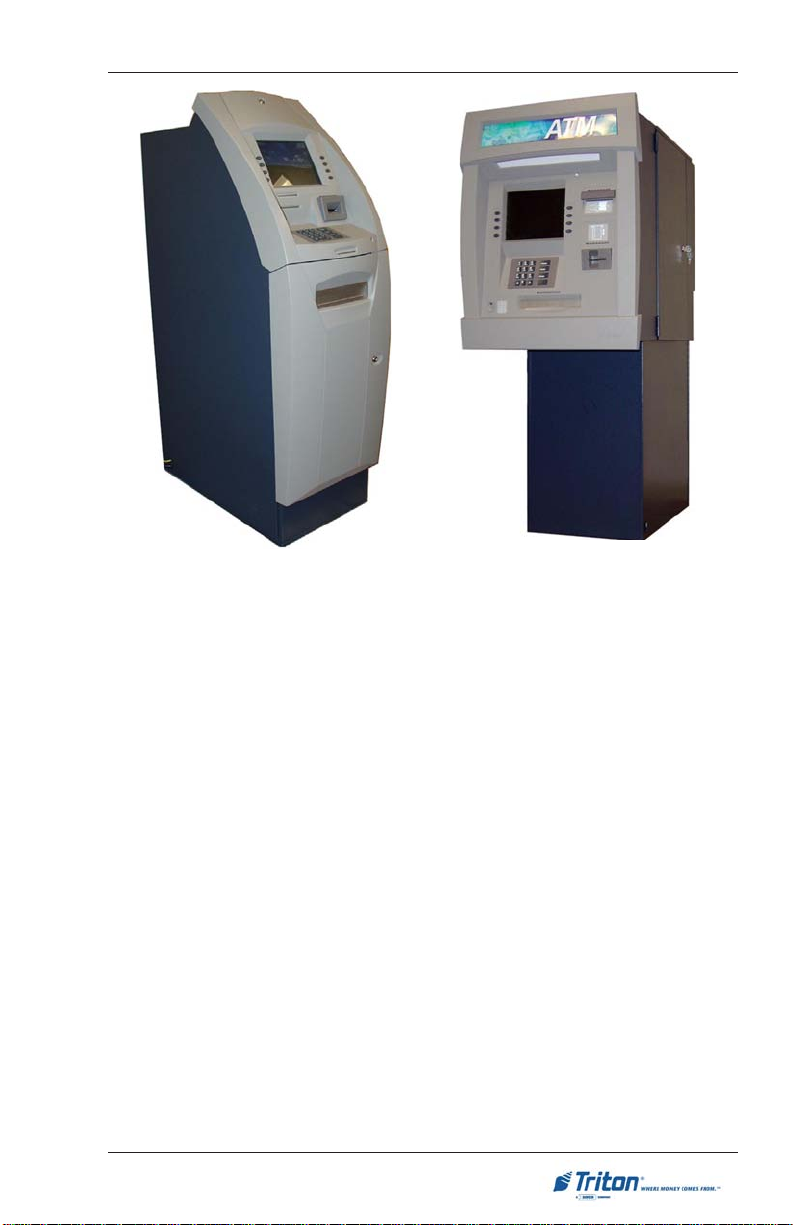
PC-BASED MODELS
The PC-based units consist of Models RL5000 and FT5000 operating on
Microsoft® Windows® XP application. Furthermore, Triton’s Prism™ ATM
software provides banks with a simple HTML interface. This revolutionary configuration offers vendors independence through XFS and makes possible a
long list of revenue generating value-added services.
Both units are equipped with an NMD-100 multi-cassette dispenser mechanism
capable of dispensing currency and non-currency items (stamps, coupons, etc)
from up to four (4) cassettes, configurable.
CLASS OF SERVICE (BUSINESS-VS-LEVEL 1)
The basic RL/FT5000XP cabinet is UL certified for Business Hours Service. This
means that the currency should be removed from the dispenser and stored in a
safe location when the business is closed to the public. Other cabinets may be
UL certified as “Level 1”, providing additional security and the ability to store
currency during non-business hours. The RL5000
allowing access to the dispensing mechanism and currency cassettes from the
front (control-panel side) of the unit. The FT5000XP is a rear-access machine.
XP
is a front-access machine,
OPERA TING SYSTEM
Both PC-based units use Windows® XP platform, a robust technological design
that provides increased stability and improved speed while maintaining reliability and low cost of ownership. The operating system supports Windows file
formats for adding custom logos and advertisements. In addition, it features
Triton’s completely custom designed motherboard.
2
Page 23
INTRODUCTION
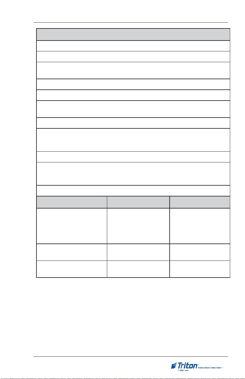
metsySgnitarepO
IIImuitnePletnIlanoitporonoreleCletnI
PXswodniWtfosorciM
:snoitpoerawtfoS
noitalumE-ecnailpmoCSFX-dradnatSnotirT
elbadnapxe,evirddrah)mm98("5.3BG04
elbadnapxe,MARDSBM652
mm462("4.01
PX
0005TF(
elbaweivthgilnuslanoitpo-)
noituloser006x008htiwyalpsidrolocAGVS)
lanoitpo,evirdlanretxeMOR-DVD/DC
PX
)
0005TF(
htiwyalpsidrolocAGVS)mm462("4.01htiwlenaPecivreSraeR
draobyekhtiwnoituloser006x008
ruoJ
lanoitpo,retnirplan
stropretsamBSU)6(xiS
troplellarap)1(enO
stroplaires)6(xiS
stolsnoisnapxeICPtib-23)2(owT
PX
snoitacificepSgnitarepO
erutarepmeT
0005TF
O
04ot01
O
05ot53-
)scinortcelE/tluaV(
O
401ot05;C
F
)lanretxE(
O
221ot03-;C
F
04ot01
PX
0005LR
O
O
401ot05;C
F
ytidimuHevitaleR
noitpmusnoCrewoP
%08ot%02
gnisnednoc-non
zH06taCAV511@A0.2
AV032@A0.1
zH05taC
%08ot%02
gnisnednoc-non
zH06taCAV511@A0.2
zH05taCAV032@A0.1
3
Page 24

MODEL RL/FT5000XP USER MANUAL
Feature Highlights
Important features of the RLXP/FTXP family are highlighted in the following list:
One to four cassette friction feed multi-denomination dispensing mechanism.
Front or rear delivery of banknotes and other value media such as tickets,
stamps, phone cards, and vouchers.
(Model FT5000
and keyboard. Allows access to Management functions for security and
ease of cassette loading and diagnostics.
XP
) Rear Service Panel (RSP) with 10.4" SVGA color display
Graphics- capable 80 mm thermal receipt printer with presenter. Optional
journal printer is available for saving journal records using traditional method
of printed copy of the electronic journal.
Enlarged (800-by-600) SVGA color LCD display (10.4 ") supports attention-getting
graphics and full-motion video.
High capacity electronic journal (2 Mb) stores transaction information for
viewing, printout, or analysis.
Dip-style card reader; optional dip EMV smart card reader, EMV motorized
card reader (Track 1, 2, 3 read), or EMV motorized card reader / encoder
(Track 1, 2, 3 read, Track 3 write).
Americans with Disabilities Act (ADA) compliant.
Audio transactions for the visually impaired.
Encrypting Pin Pad (EPP) to comply with all international encryption
standards, Triple DES compliant, optional metal EPP.
UL291 Business Hours cabinet or optional UL291 Level 1 Safe.
Electronic lock or optional Kaba Mas Cencon lock.
Multi-lingual capabilities.
Dial-up 56k baud internationally certified modem and TCPIP (Ethernet)
communications; optional wireless, SNA / SDLC, and Bisync.
4
Page 25
INTRODUCTION
RL5000
XP
FT5000
XP
ST ANDARD FEATURES
Standard features of the XP-series ATMs are summarized in the following paragraphs.
ACCESS AND TRANSACTION SECURITY
Password-Controlled Access.
Access to the ATM’ s Management Functions is protected by a password-based
access scheme. The ATM provides a “Master” password level of access and a
flexible system of “User-level” passwords. The master password provides full
access to the ATM’s Management Functions, while User-level passwords provide access to a subset of those functions, as determined by the holder of the
master password.
T ransaction Encryption.
The ATM protects all transaction and message traffic to and from the unit, using
strong encryption techniques.
MAC Data Encryption Support
The ATM implements support for the Message Authentication Code (MAC)
data encryption protocol. This capability is typically referred to as “MACing”.
MACing is a protocol supported by some processors and provides another
level of encryption protection for message traffic to and from the ATM.
5
Page 26

MODEL RL/FT5000XP USER MANUAL
Encrypting PIN Pad (EPP) Entry Device Support
Secure EPP entry device is an encryption system that offers additional protection for the customer PIN during entry at the ATM keypad. The EPP is compliant
with all international encryption standards, Triple DES, and Visa® requirements.
MULTIMEDIA INTERFACE (AUDIO/VIDEO)
The ATM’ s SVGA color display can display text and graphical content in a wide
range of colors, providing an interesting and dynamic experience to the customer. In addition, graphics can be printed on receipts. Supported multimedia
features include: T ext Effects, Ad Screens, Receipt Graphics, and Audio Output.
T ext Effects
Various special effects such as scrolling, blinking, or fading can be applied to
text messages that appear on the color display.
Ad Screens
An ad screen is a promotional or advertising graphic or motion video clip that is
displayed on the screen. Ad screens can be displayed while the terminal is idle
and while the customer transaction is being processed.
Receipt Printer Graphics
Bit-mapped graphic images (BMP) can be printed on the receipt. Like ad screen
graphics, receipt graphics are usually downloaded to the terminal via the host
processor.
Audio Output
The integrated speakers enhance the media experience by offering audio output
of voice and/or music content.
STORAGE OF FILES
The ATM can store management reports, such as the results of close operations
or diagnostic tests. Graphics files are stored and retrieved from the internal hard
disk. You may also save reports to an external memory device.
VOICE-ENABLED TRANSACTIONS
The ATM is able to provide voice feedback to sight-impaired users. By plugging
a set of headphones into the integrated headphone jack, users can receive
spoken assistance as they perform a transaction.
6
Page 27

INTRODUCTION
COMMUNICATIONS
The XP-series ATMs support communication with the transaction processor
using a variety of communications technologies. These include TCPIP, SNA/
SDLC, and BiSync.
TCPIP (Ethernet)
This method is used in applications where a central Local Area Network, or
LAN, is used to connect multiple ATMs to a central server. The ATM can be
treated as either a client or server on the network, while the server provides the
interface to a transaction processing system.
SNA/SDLC
Systems Network Architecture/Synchronous Data Link Control (SNA/SDLC) is
IBM’s version of bit-oriented protocol. SDLC is the link level protocol and SNA
provides the intelligence for the connection. SNA and SDLC use a series of
commands to control the flow of data through the network
BiSync
A major category of synchronous communications protocols used in mainframe
networks. Bisync communications require that both sending and receiving devices are synchronized before transmission of data is started. In the IBM world,
bisync was superseded by SDLC.
ELECTRONIC JOURNAL
The ATM stores transaction records, status, and other activity data in a journal
record that is stored in the ATM’ s PC hard drive. The number of journal entries
that can be stored is only limited by how much memory is available on the hard
drive.
This information can be retrieved at a later date. When needed, just the information desired can be recalled and a printout of those records can be made. Journal
entries may be viewed, printed, saved, and archived to the terminal hard drive or
to an external memory device.
TERMINAL SETTLEMENT
A suite of close functions are provided to facilitate daily balancing of the ATM’ s
internal record of transaction activity with the processor’s transaction records.
7
Page 28
MODEL RL/FT5000XP USER MANUAL
MULTI-LANGUAGE SUPPORT
The ATM has a screen language option. This option allows the terminal user to
select a preferred language (such as Spanish or French) to conduct a transaction.
MESSAGES
These are informational messages that give important information to the customer before, during, and after a transaction. Messages can be locally customized to meet local requirements. They include greeting and exit messages, terminal owner and surcharge owner identification, marketing messages, and news
tickers.
TRANSACTION AND ACCOUNT TYPE CONFIGURATION
This feature enables the terminal operator to select the types of transactions
(transfers or balance inquiries) or accounts (e.g. savings or credit card) that will
be presented to the customer. This feature does not affect the availability of
checking account withdrawal transactions, which are always presented.
REAR SERVICE PANEL (RSP)
(MODEL FT5000XP)
The RSP provides convenient user-access to most Management functions from
inside the facility. It also provides easy access to the dispensing mechanism,
loading receipt paper, and terminal shutdown.
Rear Service Panel
8
Page 29

SECTION 2
BASIC OPERA TION
9
Page 30
MODEL RL/FT5000XP USER MANUAL
INTRODUCTION
This section describes the basic operation of the terminal. The following topics
are covered:
1. Control Panel Layout. Describes the layout of the terminal’s control panel.
2. Keypad Operation. Describes the use of the alphanumeric keypads.
3. Screen Function Keys. Describes the use of the screen keys.
4. Rear Service Panel.
5. Menu-Based Operation. Provides a general overview of the terminal display
interface.
6. Accessing Management Functions. Describes the password entry
procedure that must be followed in order to access the Management
Functions area.
7. Voice-Enabled Transactions. Provides voice feedback via an integrated
output jack, enabling sight-impaired users to plug in a set of headphones
and receive spoken instructions to assist them in using the ATM.
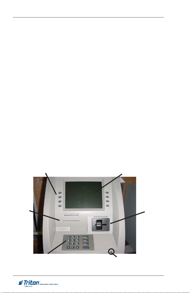
CONTROL PANEL LAYOUT (RL/FTXP)
The user interface of the terminal consists of the LCD display, receipt chute,
card reader, headphone jack (visually impaired), and 24 keys on three keypads
(menu and main keypads).
Receipt
chute
Menu keys
Main keypad Headphone jack
Fig. 2-1a. Control panel layout (RL
10
LCD screen
XP
)
Card reader
Page 31

BASIC OPERATION
Main keypad
Headphone
jack
Menu keys
Fig. 2-1b. Control panel layout (FT
KEYP AD OPERATION
LCD screen
XP
)
Receipt
chute
Card
reader
See Figure 2-2 and Table 2-1. The main keypad consists of 10 alphanumeric
keys, two arrow keys and four large control keys, all located in a 16-key group
beneath the LCD display. The table lists the keys and their functions.
The keypad has integral raised Braille symbols to conform to the requirements
of the Americans with Disabilities Act.
CTRL key
Fig. 2-2. Alphanumeric keypad
11
Page 32

MODEL RL/FT5000XP USER MANUAL
PAMDRAOBYEKTNORF-1-2ELBAT
YEKPAMDRAOBYEKNOITCA
worrAtfeL
worrAthgiR
retnEretnE .nottubde
lecnaCepacsE.golaiDehtnoLECNACstceleS
raelCBAT .enilwenatresnilliw,
yeKLRTC
)yeKknalB(
9-09-0
pUroworrAtfeL
worrA
roworrAthgiR
worrAnwoD
-
ecapS
.lortnoctsilanipusevoM-
.nottubsucofehtstceleS-
.lortnoc
suoiverpehtotsucofegnahC-
(dleiFtnerruCnidrawroFllorcS-
.lortnoctxenehtotsucofegnahC-
.lortnoctsilaninwodsevoM-
.nottuboidarroxobkcehcaselggoT
.noitpoxobgolaiddeificepsehttceleS-
liw,xobtidenaedisninehW-
.)sexoBtidEdnaobmoCrof(dleiFtnerruCnikcaBllorcS-
.)sexoBtidEdnaobmoCrof
tcelesasesserprogolaiDehtnoRETNEstceleS
sexobtxetenil-itlumroF.golaiDehtnodleiFtxeNotevoM
.retcarahcciremundeificepsehtyalpsidl
Table 2-1. Keyboard map.
SCREEN FUNCTION KEYS
Refer to Figure 2-3. The eight keys, 4 on each side of the LCD, are called screen
function keys. They are used in the selection of screen options that can appear
along the right and left side of the display. These keys are designated F1 through
F8. A screen function key is only active when a corresponding function or menu
option is present next to that key.
F1
F2
F3
F4
Figure 2-3. Screen function keys.
12
F5
F6
F7
F8
Page 33

BASIC OPERATION
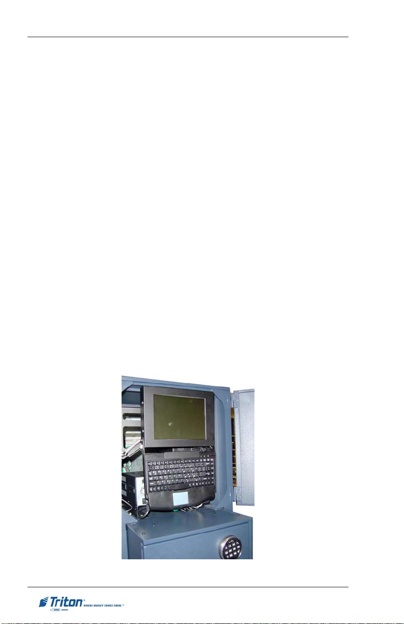
REAR SERVICE PANEL (MODEL FTXP)
The Rear Service Panel (RSP) houses a 10.4" (264mm) SVGA color display with
800 x 600 resolution and a keyboard with mouse pad. This provides convenient
user-access to most Management functions from inside the facility . The assembly also pivots out allowing access to the PC assembly, power supply, and
optional printer assembly.
Figure 2-4. Rear service panel (display/keyboard).
13
Page 34

MODEL RL/FT5000XP USER MANUAL
MENU-BASED OPERATION
The terminal operates as a menu driven system. Messages and menu options
presented on the LCD display screen guide the user’s actions. The desired
menu option is selected by pressing one of the screen keys located to the left
and right of the display. For the purpose of security, many screens timeout after
a preset time interval, usually 30 seconds. The timeout length may vary depending on the function being performed.
When a screen timeout occurs, a screen is presented which asks the user if more
time is needed. If the user chooses NO, the Customer Welcome screen will be
presented. If YES is chosen, the user is returned to the function that was active
prior to the timeout. If the user does not make a selection within an additional
30-second countdown period the terminal will automatically go to the Customer
W elcome screen.
Shortly after the unit is turned on, the top menu will be displayed. An example
top menu is shown in Figure 2-5. From the top menu, you can either:
 Activate the terminal to perform customer transactions by pressing the
key next to Customer Transaction.
 Enter the terminal system management area by pressing the key next to
Management Functions.
If you do not select a menu choice within 30 seconds the terminal will automatically default to the Customer W elcome screen (a benefit of this feature is that in
the event of a power interruption the terminal will automatically begin accepting
customer transactions shortly after power is restored).
Fig. 2-5. Top menu.
14
Page 35

BASIC OPERATION
VOICE-ENABLED TRANSACTIONS
The terminal provides voice feedback via an integrated output jack, enabling
sight-impaired users to plug in a set of headphones and receive spoken instructions to assist them in using the ATM. Figure 2-6, headphone jack location,
shows the location of the headphone jack on the RL5000XP.
Fig. 2-6. Headphone jack location.
Raised symbols helps a user locate the headphone jack. The ATM will automatically detect when a headphone has been plugged into the jack, and will immediately switch into voice mode. Initially, a brief spoken tutorial will orientate the
customer to the ATM control panel interface. Once the customer begins a transaction, spoken prompts will provide feedback and guide the customer through
the successful accomplishment of the transaction.
15
Page 36

MODEL RL/FT5000XP USER MANUAL
THIS PAGE INTENTIONALLY LEFT BLANK
16
Page 37

SECTION 3
REPLENISHING CASSETTES
17
Page 38

MODEL RL/FT5000XP USER MANUAL
INTRODUCTION
The purpose of this section of the
manual is to describe the procedures for:
(1) removing and replacing note cassettes, (2) loading cassettes, and (3) removing and replacing the reject notes
(as applicable). Information concerning
note handling and quality issues are explained where appropriate.
DISPENSING MECHANISM
The RL/FTXP-series ATMs use an NMD100, friction-feed dispensing mechanism
to store and deliver notes and other media to the customer. The mechanism is
located in the lower security container
of the unit. It holds multiple cassettes
and a single reject cassette. The note
capacity for the cassettes is approximately 2750.
The dispensing mechanism delivers the
appropriate number of notes from the
note cassettes to fulfill the customer’s
withdrawal request. The purpose of the
reject cassette is to accept and hold
notes that have been transferred from
the note cassettes but not dispensed.
Some situations that could cause the
mechanism to reject notes are:
The mechanism is able to reject single
notes or bundles. A bundle reject occurs when more than one note is rejected at the same time. There are two
compartments within the reject cassette to keep notes in these two categories separated. The top compartment within the cassette can hold a
maximum of 250 bundle-notes; the
lower compartment can hold up to 100
single-note rejects.
IMPORTANT! The first time the dispenser is set up, or if a new note cassette is installed, the mechanism will
enter a learning mode, during which it
will reject 7-15 notes as it learns the
thickness of the currency or other media. W ith multiple cassettes installed,
the number of test rejects could almost fill the single-note compartment
of the reject cassette. In such cases, it
is recommended that you remove any
rejected notes from the unit before
placing the ATM back into service.
**CAUTION**
DO NOT RECYCLE REJECTED
NOTES INTO A CASSETTE!
Doing so could cause more rejects
and/or currency jams.
Multiple notes stuck together
Note width too short or long
Notes skewed in feed path
Notes too close together in
feed path
Notes not claimed by customer
(after a preset timeout the mechanism will retract the notes and
send them to the reject cassette).
NOTE CONDITION
The number of rejects can be directly
influenced by the technique used to
load the cassettes and the quality of
the currency. Notes loaded into the
mechanism cassettes must be in “fit”
condition if a high level of performance (low reject and failure rate) is
expected from the unit. “Fit” notes
are defined as those that do not possess any of the defects listed here:
18
Page 39

REPLENISHING CASSETTES
U
SED NOTE DEFECTS
Adhesive or “sticky” substances
on the surface of the paper.
Tears extending more than 1/2”
from the edge of the currency.
Tears, holes, or missing sections
in the body of the currency.
Tape on the surface of the currency
used for repairing, patching or any
other purpose.
Remove foreign objects (e.g. pins, pa-
per clips, crumbs, etc.).
Remove torn or very worn notes.
Straighten any folded notes.
Staples, pins, or any other foreign
body attached to the notes.
Corner folds of a size greater than
1/2” on either axis.
Two or more notes joined by any
means.
Excessively crumpled or crinkled.
NEW OR UNCIRCULATED NOTE DEFECTS
All the conditions listed for used
notes.
Excessive bowing due to condi-
tions of packing and storing.
New or uncirculated currency must
be “burst” and fully separated prior
to loading into cassettes.
PREP ARING NOTES
Use the following procedures to prepare notes before inserting them into a
note cassette.
Figure 4-1. Removing band.
Figure 4-2. Removing torn/worn
notes.
N
EW OR UNCIRCULATED NOTES
Remove the band around each bundle
of notes. Separate the notes from each
other by:
Striking the bundle hard against
the edge of a table or similar ob ject.
Flipping through each bundle of
notes in both directions at each
end.
Using a note counter.
PREPARING USED NOTES
Remove the band around each
bundle of notes.
19
Page 40

MODEL RL/FT5000XP USER MANUAL
REPLENISHING CASSETTES
To perform a cash replenishment, enter Management Functions > Terminal
Settlement Functions > Replenish Cassette(s). Follow the prompts to <Unlock>, load cassettes, and <Lock> cassettes.
REMOVING NOTE CASSETTES
1. Open the electronic lock on the security container door and open the door
to gain access to the dispensing mechanism.
2. To remove the selected note cassette, grasp the cassette handle with one
hand while holding the mechanism in place with the other hand (See Figures
4-3a and 4-3b). Pull the cassette out slightly. Place one hand underneath to
support the cassette as you slide it completely out of the unit.
Figure 4-3a. Cassette removal
(Model RL5000XP shown).
**CAUTION**
The “throat” assembly on the mechanism is not a load bearing structure!
Do not grasp or apply any pressure
to the throat.
3. Continue to support the bottom of
the cassette to keep it level as you
place it on a table or other flat surface. If the cassette has a loading
arm, fold it down, which will raise
the rear of the cassette and allow
gravity to help keep the notes
neatly stacked during the loading
process (Figure 4-4).
Figure 4-3b. Cassette removal.
Figure 4-4. Cassette w/loading
arm down.
20
Page 41

REPLENISHING CASSETTES
OPENING NOTE CASSETTES
1. Insert the key into the cassette lock (Figure 4-5). To unlock the cassette,
apply inward pressure on the key while turning it clockwise to the stop
position (approximately a quarter-turn). Open the cassette by simultaneously
pressing the release button and lifting the lid. Flip the lid back fully, allowing it to rest on the table or other flat surface (Figure 4-6).
Figure 4-5. Key inserted.
2. Move the pusher plate to the rear of the cassette (toward the handle).
Ensure the pusher plate is fully back. It should stay in this position (Figure
4-7).
Figure 4-7. Open lid and move pusher plate back.
Figure 4-6. Release button.
21
Page 42

MODEL RL/FT5000XP USER MANUAL
LOADING NOTE CASSETTES
1 . Load the cassette with currency. The shape of some notes may be affected
by conditions of storage or bundling, preventing them from forming neat
even piles. If not corrected, such conditions may cause notes to be rejected
by the dispensing mechanism. T o compensate for the most common conditions of slanting or cupped note piles, follow the directions given here.
Notes with no apparent shape problems are referred to as “common” notes.
• Slanting pile
To avoid dispensing problems caused
by a “slanting” pile, put the notes in
neat bundles of no more than ½ to ¾
inches in thickness. Turn every other
bundle around to minimize slanting of
the pile (Figure 4-8).
• Cupped bundle
To avoid dispensing problems caused
by cupped bundles, turn all the bundles
with the cupped side towards the dispense opening (Figure 4-9).
• Common notes
Place the prepared bundles in the cassette.
2 . Level the note pile. Compress the
note pile slightly by hand. Single
notes must not protrude from the
bundle (Figure 4-10).
Figure 4-8. Slanted piles.
Figure 4-9. Cupped piles.
Figure 4-10. Leveling note pile.
22
Page 43

REPLENISHING CASSETTES
3. Move the pusher plate against the notes with just enough pressure to hold
the notes in the correct position when closing the lid and inserting the
cassette into the mechanism (Figure 4-11).
4. Move the white plastic levers (Pawls) on the pusher plate to their fully
extended position. This will allow the pusher plate to retract and release
pressure from the note stack when an unlock command is sent to the
dispenser (Fig. 4-12).
Figure 4-11. Moving pusher plate
against notes.
5 . Close the cassette lid. Fold the lid
down to its locked position. The
release button should “pop” out,
allowing the lid to mate cleanly with
the body of the cassette. You may
need to “tap” the lid firmly along
the front edge to achieve this. Turn
the key counterclockwise to lock
the cassette (Figure 4-13).
Figure 4-12. “Pawls” extended.
Figure 4-13. Closing lid.
INST ALLING NOTE CASSETTES
Using the reverse of the steps used to remove the note cassette from the mechanism, slide the note cassette into its slot in the mechanism. Keep the cassette
level as you load it, and make sure the cassette is fully inserted. Once all cassettes have been filled and reinserted, they are ready to be <Locked> into
position following the Replenish Cassette(s) function prompts.
* IMPORT ANT *
Before locking cassettes, it is recommended to check the Reject Cassette for
any rejected notes. The procedures for the reject cassette are described next.
23
Page 44

MODEL RL/FT5000XP USER MANUAL
REMOVING THE REJECT CASSETTE
*IMPORTANT*
If you remove the reject vault with power applied, the terminal will
sense this and automatically reset the rejected note count to ZERO.
Therefore, to ensure an accurate rejected note count NEVER RE-
MOVE THE REJECT V AULT WITH POWER APPLIED WITHOUT
CHECKING FOR AND REMOVING ANY REJECTED NOTES!
1 . Ensure cassettes are <Unlocked>. To remove the reject cassette, (top chan-
nel) grasp the cassette handle with one hand while holding the mechanism
in place with the other hand. Pull the cassette out slightly. Place one hand
underneath to support the cassette as you slide it completely out of the
unit. Place it on a level surface (Figures 4-14a and 4-14b).
Figure 4-14a. Removing the
reject vault.
Figure 4-14b. Reject vault ready
to open.
OPENING THE REJECT CASSETTE
1. Insert the key into the cassette lock. To unlock the cassette, apply inward
pressure on the key while turning it clockwise to the stop position (approximately a quarter-turn). Open the cassette by simultaneously pressing the
release button and lifting the lid. Flip the lid back fully (Figures 4-15 and 4-
16).
Figure 4-15. Key inserted.
24
Figure 4-16. Opening lid.
Page 45

REPLENISHING CASSETTES
2. The reject cassette is now open for collecting any rejected bundle notes.
These will be present in the folding tray. After retrieving any rejected bundle
notes, lift the folding tray and check underneath for any rejected single
notes (Figures 4-17 and 4-18).
3. After removing any rejected notes, close the lid. Fold the lid down to its
locked position. The release button should “pop” out, allowing the lid to
mate cleanly with the body of the cassette. Turn the key counterclockwise
to lock the cassette.
Figure 4-17. Bundle reject tray. Figure 4-18. Single reject
compartment.
INST ALLING THE REJECT CASSETTE
Using the reverse of the steps taken to remove the reject cassette, slide the
cassette back into its slot in the mechanism. Make sure the cassette is fully
inserted. Following the Replenish Cassette(s) function prompts, <Lock> all
cassettes.
25
Page 46

MODEL RL/FT5000XP USER MANUAL
VERIFY OPERATION
1. Close and lock the security cabinet.
2 . Verify the cassettes are <Locked> in the dispenser.
3. In Management Functions, select D
4 . Select the T
EST DISPENSE option. Enter # of notes to be dispensed (1-5) from
IAGNOSTICS, then CASH DISPENSER.
the individual cassettes that are installed (“A”, “B”, “C”,or “D”). Select
PERFORM TEST. The Test Dispense operation will start.
Figure 4-19. Enter # of notes.
5 . The Test Dispense command instructs the dispenser to dispense, minimum,
one note from each installed and operational cassette into the reject cassette.
This test exercises the dispenser without sending notes to the exit.
6. After completion of the Test Dispense, the following prompt is displayed
(Figure 4-20).
Figure 4-20. Test dispense prompt.
26
Page 47

SECTION 4
PREVENTA TIVE MAINTENANCE
27
Page 48

MODEL RL/FT5000XP USER MANUAL
INTRODUCTION
This section of the manual covers preventive and corrective maintenance
procedures appropriate for user person-
nel. The following areas are covered:
EPLENISHING PAPER RL/FT
1. R
(RECEIPT PRINTER). Describes how
to replace a spent receipt paper roll.
2. R
EPLENISHING PAPER (JOURNAL
PRINTER). Describes how to
replace the spent journal paper roll.
3. L
OADING INK CARTRIDGE (JOURNAL
PRINTER). Describes how to load
the printer ink cartridge.
4. C
LEANING THE ENCLOSURE. The
proper way to clean the ATM
housing and displays..
5. C
ARD READER CLEANING. The
recommended card reader cleaning
technique.
*IMPORTANT*
Only qualified service personnel
are authorized to repair or service the terminal. Should a malfunction occur , DO NOT attempt
to service the unit yourself! Contact your T riton certified service
provider!
XP
REPLENISHING RECEIPT PAPER
(RL5000XP)
***WARNING***
XP
The control panel for the RL
provided with a pneumatic piston
to prevent the door from extending too far when opening and provides some dampening when being
closed. Do not force the piston
when closing the control panel!
* NOTE *
Triton recommends the use of 20#
thermal printer paper (Triton P/N
05403-00053). This receipt paper has
been shown to improve performance
and reliability .
NOTE: This operation must be completed with the AC power applied to
the ATM.
1. Open the top of the ATM by
unlocking the top enclosure and
pulling the hinged door forward.
2. If paper remains on the roll, cut
the paper between the roll and the
input to the printer with a pair of
scissors.
is
28
Page 49

PREVENT ATIVE MAINTENANCE
3. Press and hold the paper feed
button until the paper clears the
front of the printer.
** CAUTION **
Do not pull the paper backward
through the printer . This may leave
paper fragments that can cause paper jams.
4. Remove the existing paper roll or
empty spindle (as appropriate) from
the paper support bracket.
5. Unwind about 18 inches from the
end of the new roll of paper. Using
scissors, cut off the excess. Make
sure all the paper that has glue on
it is removed from the end of the
roll.
6. Install the new paper roll on the
spindle. Place the paper roll (w/
spindle) on the paper support
bracket by sliding ends of spindle
on to the bracket shown. Ensure
the paper feeds from the
the roll!
TOP of
Paper feed
button
7. Insert the edge of the paper roll
into the printer take-up slot.
Note: Paper feeds
The printer will automatically grip
and pull the paper into the paper
path. If the paper feeds
automatically, skip to Step 10. If
the paper does not feed
automatically, continue with Step
8.
over the bar.
29
Page 50

MODEL RL/FT5000XP USER MANUAL
8. If the paper is not automatically
taken-up by the printer, check the
tension roller lever on the printer
chassis. Pull the pin located on the
right side of the printer bracket
shown. Rotate the assembly
towards the front of the control
panel.
9. The blue tension lever is located
on the left side. It must be in the
closed position (blue lever facing
towards the right). If not, just move
the lever (moves in 3 positions) to
the correct position. Close the
cutter assembly and retry to feed
the printer paper. If successful,
continue with Step 10. If the paper
is not taken up automatically,
contact your service provider.
10. Close and lock the control panel.
Go to Management Functions >
Diagnostics > Printer and perform
a
“Print Test Data”.
Release pin
30
Page 51

PREVENT ATIVE MAINTENANCE
REPLENISHING RECEIPT PAPER
(FT5000XP)
NOTE: This operation must be com-
pleted with the AC power applied to
the ATM.
1 . Open the left side service panel on
the cabinet sleeve.
2. If paper remains on the roll, cut
the paper between the roll and the
input to the printer with a pair of
scissors.
3. Press and hold the paper feed
button until the paper clears the
front of the printer.
** CAUTION **
Do not pull the paper backward
through the printer . This may leave
paper fragments that can cause paper jams.
* NOTE *
Triton recommends the use of 20#
thermal printer paper (Triton P/N
05403-00053). This receipt paper has
been shown to improve performance
and reliability .
Paper feed
button
Paper support
bracket
4. Remove the existing paper roll or
empty spindle (as appropriate) from
the paper support bracket.
5. Unwind about 18 inches from the
end of the new roll of paper. Using
scissors, cut off the excess. Make
sure all the paper that has glue on
it is removed from the end of the
roll.
6. Install the new paper roll on the
spindle. Place the paper roll (w/
spindle) on the paper support bracket by sliding ends of spindle on
to the bracket. Ensure the paper
feeds from the
TOP of the roll!.
31
Page 52

MODEL RL/FT5000XP USER MANUAL
7. Insert the edge of the paper roll
into the printer take-up slot.The
printer will automatically grip and
pull the paper into the paper path.
If the paper feeds automatically,
skip to Step 10. If the paper does
not feed automatically, continue
with Step 8.
8. If the paper is not automatically
taken-up by the printer, check the
tension roller lever on the printer
chassis. Grasp the handle shown
and lift up. Pivot assembly down
until assembly is fully open.
9. The blue tension lever is located
on the right side. It must be in the
closed position (blue lever facing
towards the right). If not, just move
the lever (moves in 3 positions) to
the correct position. Close the
assembly and retry to feed the
printer paper. If successful,
continue with Step 10. If the paper
is not taken up automatically,
contact your service provider.
10 . From the Rear Service Panel, go to
Management Functions >
Diagnostics > Printer and perform
a
“Print Test Data”.
32
Page 53

PREVENT ATIVE MAINTENANCE
REPLENISHING PAPER
(JOURNAL PRINTER)
*** W arning ***
Remove power from the Journal Printer during any servicing that requires the user to insert fingers into the printer wheel area.
NOTE: The following steps reference Figure 6-1 and 6-2.
Cut / Feed
switch
Bail
Bail slot
Figure 6-1. Journal printer.
1 . Access the journal printer and turn the power switch OFF .
2. Lift the Bail (item 3) and remove any paper that may be inside the printer .
Close the Bail.
3 . Place the paper roll (item 4) in the Paper Handler (item 5). The paper roll must
have a roll pin through its center.
Paper “out’
sensor
Power switch
33
Page 54

MODEL RL/FT5000XP USER MANUAL
Figure 6-2. Loading journal paper.
4 . Direct the paper (item 6) from the paper roll (item 4) through the Paper Out
Sensor and down into the Guide slot (item 7) until the paper stops against
the Feed Mechanism (item 8). Remove the Journal T ake-up Carriage (item 9).
5. The paper is now ready to be advanced automatically through the rest of
the printer assembly. First, turn the power switch ON. After a few seconds,
press the Feed Switch until the Feed Mechanism (item 8) passes
approximately 5-7 inches of paper beyond the Bail (item 3). You may need to
apply hand pressure on the paper, directed towards the Feed Mechanism
(item 8), in order to activate the Feed Mechanism (item 8).
6 . Lift the Bail (item 3) and pull the journal paper (item 6) out of the Bail Slot
(item 10).
7 . Guide the journal paper (item 11) through the Journal Slot (item 12). Attach
the leading edge to the clip on the Journal T ake-up carriage (item 9).
Steps 8 and 9 redirect the journal paper to the Journal Take-up carriage.
8. Advance the Journal Take-up Carriage (item 9) by hand until the journal
paper (item 11) is taut.
9 . Attach the Journal Take-up Carriage (item 9) to its mounting bracket.
1 0. The journal paper is now loaded.
34
Page 55

PREVENT ATIVE MAINTENANCE
LOADING INK CARTRIDGE
(JOURNAL PRINTER)
NOTE: The following steps reference Figures 6-3 through 6-6.
Cut / Feed
switch
Bail
Bail slot
Figure 6-3. Journal printer.
1 . Access the journal printer and turn the power switch OFF .
2 . If there is a used ink cartridge already loaded, remove it by opening the Bail
and pulling the cartridge directly off the Drive shaft (Figure 6-4).
Bail
(Closed position)
Paper “out’
sensor
Power switch
Drive shaft
Figure 6-4
Front view of ink cartridge area.
35
Page 56

MODEL RL/FT5000XP USER MANUAL
3. Before inserting the new ink
cartridge, turn the cartridge knob
“counterclockwise” until ribbon is
taut (Figure 6-5).
4 . Open the Bail. Carefully mount the
ink cartridge onto the drive shaft,
keeping the ribbon between the
Platen and the Printhead (Figure
6-6).
5 . Thread the ribbon through the Guide slot and, before closing the Bail, make
sure the ribbon is still taut by turning the cartridge knob counterclockwise
(Figure 6-6).
6 . Close the Bail. The ink cartridge is now loaded.
Platen
Bail
(Open position)
Cartridge knob
Ink cartridge
Figure 6-5. Turn knob
counterclockwise.
Ribbon
Guide slot
Printhead
Knob
Figure 6-6. Ink cartridge installed.
36
Page 57

PREVENT ATIVE MAINTENANCE
CLEANING THE ENCLOSURE
The ATM front panel/trim is highly durable, resisting scratches and finger
smudges. However, occasional cleaning of the front panel and the plastic
enclosure may be desirable. A soft dry
or slightly damp cloth may be used for
cleaning. For best results, use a weak
solution of a mild detergent and water .
** CAUTION **
A void using abrasive cleaners on
any surface of the terminal. Do
not spray liquid cleaner directly
on the unit.
CLEANING THE DISPLAY
The Liquid Crystal Display (LCD) on
the front of the ATM has a glass protective shield that should be cleaned
only with a soft lint free cloth, dampened with a weak solution of a mild detergent and water.
CARD READER CLEANING
Special cleaning cards (P/N 06200-
00055) are available for proper maintenance of the card reader. The reader
should be cleaned at least once a month
by inserting and removing a cleaning
card as shown below. It may be necessary to clean the card reader more often in locations that see heavy usage.
1 . Remove the cleaning card from the
sealed pouch.
2. Insert the cleaning card into the
card reader and move in and out
several times.
3 . Remove the cleaning card and turn
over to use other side.
4 . Insert again several times.
5 . Remove cleaning card and discard.
** CAUTION **
Do not use any abrasive cleaners
on the window, as it will scratch.
Do not spray liquids onto the
screen, as they may run down inside the unit and cause damage.
37
Page 58

MODEL RL/FT5000XP USER MANUAL
THIS PAGE INTENTIONALLY LEFT BLANK
38
Page 59

SECTION 5
MANAGEMENT FUNCTIONS
39
Page 60

MODEL RL/FT5000XP USER MANUAL
INTRODUCTION
This section describes the Management Functions available running Prism 912
emulation controlling the ATM.
WHAT IS PRISM 912-EMULATION?
Prism offers true, open-ended, object-oriented architecture using industry
standard Microsoft® development tools. The unique software design and
integrated W eb browser enables Prism to be plug compatible with existing ATM
processor networks without changes to the existing host system. The Prism
application can operate in an ATM network, alongside standard OS/2-based
ATMs, without any host changes. But it is more than a standalone application.
Prism application is also flexible and can be customized at all levels. Prism
liberates ATM content from the rigid and expensive development requirements
of proprietary systems. Specialty services, advertising and cross selling are
easy to implement with Prism, allowing FI’s to extend the same brand
differentiation used in branches and on FI’s Web site out to the ATM channel.
The following summarizes the features and benefits of the Prism application:
S
EAMLESS INTEGRATION
· Prism is ‘plug-and-play’ in today’s MDSi 912 ATM network - without
changes to existing host download and ATM infrastructure
· Provides concurrent support of legacy (MDS 912) transactions and
content from a web-server without host changes.
· Compatible with all major ATM Protocols – TCP/IP, SNA/SDLC and
Bisync communications.
· All application software is industry standard MS W indows compliant
with CEN-XFS universal standards.
· Prism permits the financial institutions to implement web technology
without any disruption to existing ATM operations or back-end
changes.
I
NVESTMENT PROTECTION
· Prism was certified on all major ATM networks in North America.
· Prism is transparent to the ATM driving platform and easily transportable to a new host ATM device driver without any re-programming or
vendor intervention.
· Fully preserves the financial institution’s investment in technology.
40
Page 61

MANAGEMENT FUNCTIONS
• Prism allows the FI to convert 912 screens into HTML format obviating
any additional resource burden or vendors’ Professional Services intervention.
· Prism is multi-vendor capable.
WHAT IS MEANT BY A “WINDOWS-BASED” A TM?
The current ATM environment is still one that is largely driven in a Diebold® or
NCR® emulation environment that uses traditional “states and screens” –
command sets. The host processor sends “states and screens” to the ATM and
which the ATM uses to build transaction requests and display content to its
user. With that in mind, we define a “W indows driven” ATM as one which: runs
on the Microsoft® Windows® 2000 or XP operating system platform;
communicates using the TCP/IP communications protocol, or a combination of
TCP/IP and another protocol such as Bisync when used in conjunction with a
legacy transaction processing emulation such as 912; takes advantage of Web
technologies, including an industry standard browser (Internet Explorer) and
HTML Web page and development tools which, used together, accurately
represent as well as enhance the current states and screens methodology; is
powered by an underlying ATM software application such as Prism that builds
a new, content-rich HTML-based graphical user interface.
Working together, these characteristics enable new types of enhanced services
that lower cost, increase brand reach, extend online banking capabilities and
grow new revenue streams. It is important to keep in mind, however, that while
Web-enabled ATMs deploy Web technologies, they are neither designed nor
intended for use as a Web surfing device.
W
HAT DIFFERENTIATES THE WINDOWS-BASED ATM FROM ITS PREDECESSOR?
Windows based ATMs are the new generation of ATMs that are broadly distinct from their predecessors in the technology they use and the business benefits they can deliver. Existing ATMs operate in closed, proprietary system, and
most of them run OS/2, an operating system that will find waning support, both
from IBM, its developer, as well as from ATM manufacturers.
In an increasingly competitive retail banking market, OS/2 based ATMs no longer
meet the changing competitive and regulatory requirements that challenge today’s
financial institutions. Windows based ATMs promise to dramatically alter the
role of ATMs in the delivery of banking products and services, and ultimately in
the relationship between financial institutions and their ATM customers.
41
Page 62

MODEL RL/FT5000XP USER MANUAL
XP PRISM SOFTWARE ARCHITECTURE
The above diagram is a high level overview of the Triton A TM software architecture running Prism. The base operating system is W indows XP Pro and at the
low end you have hardware devices with their firmware that communicate to the
WOSA middleware developed by KAL. Prism application conforms to WOSAXFS standards. WOSA-XFS allows higher-level applications to communicate
with low-level device drivers. The T riton ATM WOSA-XFS compliant application is developed by KAL. Almost all other ATM vendors in the industry use
KAL middleware for their application. On top of that we have the Prism application to perform 912 emulation and W eb transactions. At the core of all this is the
Internet Explorer browser that is used to display all screen content in HTML
format. The same browser is also used to display host download text data to the
consumer. This is where Prism application integrates both legacy 912 transactions and web-based transactions into a single screen format that is completely
transparent to the end user. This enables FI’ s to modify the look and feel of the
host transaction screens with engaging HTML screens.
The 912-emulation defines the format of the messages exchanges between an
ATM and the host processor for processing consumer financial transactions.
42
Page 63

MANAGEMENT FUNCTIONS
Prism 912-emulation is based on Diebold® iSeries 912 message standard. Prism
conforms to 912 message standards for:
· Screens and States downloads
· Support all Screen 912 screen display functions
· 912 operational and message commands, and status messages
· Support 912 state types
· Operational commands
· Function commands
· Full transaction support
· Withdrawal, deposit, balance inquiry…etc
For those FI’s that deploy a Triton ATM with Prism application, there will be no
changes required to support 912, provided the FI currently has 912-emulation
software running at the host end. It will be a “plug-and-play” implementation.
43
Page 64

MODEL RL/FT5000XP USER MANUAL
DISPLAY POWER -UP SEQUENCE
When the ATM is powered on, or has been re-booted, “Out of Service” is displayed on the front screen. The rear screen (FTXP model) will display the “ATM
Status” screen. After the power-up sequence is complete, the “ATM Startup
Options” screen will be displayed on the front LCD of the RL
startup option will be displayed on the rear LCD - the front LCD will display the
“Out of Service” screen.
Figure 5-1. Start-up menu displayed on front LCD (RLXP) and rear LCD (FTXP).
The user selects the desired function by pressing either number <1> for Man-
agement Functions or number <2> for Customer Transactions.
XP
. On the FTXP, the
ACCESSING THE MANAGEMENT FUNCTIONS MENU
When the Customer Welcome screen is displayed, you can access the Management Functions menu by following the procedure described next.
 Press and hold down the blank <CTRL> key; while holding down the
<CTRL> key, press the <1> key. Release both keys. After a moment the
“Security Login” screen will be displayed.
DEF AUL T MASTER P ASSWORD
The default master user ID is “00” and the password is “1234”. The Master
User ID is always ‘00’ and can not be changed!
To enter Management Functions as the master user, enter “00” and “1234”.
CHANGE THE MASTER P ASSWORD IMMEDIA TELY TO PREVENT
UNAUTHORIZED ACCESS TO THE ATM!
44
Page 65

MANAGEMENT FUNCTIONS
Figure 5-2. Enter your Master or User password.
Y ou must enter an appropriate password in the dialog box that appears when the
Management Functions option is selected. The password will consist of a 2-digit
ID code and a password of 4-12 digits; for example, 051234 could be a password
entry consisting of an ID code of 05 and a password of 1234.
 Enter the 2-digit ID code, then press <Enter>.
 Enter your password and press <Enter> again.
When a valid login is entered, the Main Menu screen will be displayed (Figure 5-
3).
Figure 5-3. Main Menu screen.
45
Page 66

MODEL RL/FT5000XP USER MANUAL
SWITCHING SCREENS (MODEL FTXP)
The FTXP has two (2) displays - the front (Customer side) and rear (Operator
service side). You can access all menu options in the Management functions
from the front display. When accessing Management functions from the rear
display, certain options (Key Management) will need to be configured from the
front display. Y ou will be prompted to switch screens when this occurs (Figure
5-4).
Figure 5-4. Switch screen prompt.
Select the <CTRL> button and the following screen will appear (Figure 5-5).
Press number <3> to switch display access. You will again see the “Security
Login”. Enter your ID code and password to access Management functions.
Figure 5-5. Control key menu screen.
46
Page 67

MANAGEMENT FUNCTIONS
FUNCTION AVAILABILITY
Once you have entered the Main Menu, you may perform any of the functions
allowed by the type of password used (access level).
Each Main Menu option description will include the function name, instructions
for accessing the function, a description of the function, and any associated
factory default values.
The Main Menu screen allows the service provider/terminal operator to access
the following Management functions:
1. T erminal Settlement Functions. Used to view/clear settlement totals and
replenish cassettes.
2. Diagnostics. Used to perform terminal hardware testing and to view test
results.
3. Electronic Journal. Used to manage the ATM’s journal functions, such
as export, save, and perform queries.
4. Password Maintenance. Used to add/delete users and modify terminal
access privileges.
5. System Parameters. Used to shut down or restart the terminal, update
terminal software, and set terminal date/time settings.
6. T erminal Configuration. Used to view/edit terminal operating parameters
such as terminal ID, status reporting, state settings, cash dispenser setup,
screen settings, audio setup, printer setup, and communication settings.
7. Key Management. Used to enter encryption keys, which protect
communications between the ATM and the transaction processing service
provider.
8. T erminal Status.
parameters, and export trace files..
Used to view terminal status reports, save and restore
* Note *
The availability of some Management Functions will depend on such factors as
types of optional hardware installed, user password options, etc. In cases where
a function is not applicable or available, the option will be “grayed out” or
otherwise disabled.
47
Page 68

MODEL RL/FT5000XP USER MANUAL
Management Reports
Many Management Functions, such as T erminal Settlement, Journal, and Diagnostic functions, produce a report summarizing the results of the operation. Most
reports are displayed in a Management Report dialog, which you can use to print the
report to the receipt printer or save to an external memory device.
The buttons on the Management Report dialog let you perform the following actions: (Figure 5-5)
4. Page Up. Scrolls the report up a maximum of one full page.
7. Page Down. Scrolls the report down a maximum of one full page.
6. Home. Moves directly to the first page of the report.
9. End. Moves directly to the last page of the report.
1. Save. Saves the report as a text file to an external memory device.
2. Print. Sends the report to the terminal receipt printer for hardcopy output.
Figure 5-5. Management Report menu (sample).
48
Page 69

MANAGEMENT FUNCTIONS
TERMINAL SETTLEMENT FUNCTIONS
TERMINAL SETTLEMENT FUNCTIONS
TERMINAL SETTLEMENT FUNCTIONS MENU OPTIONS ..................... 50
VIEW A TM SETTLEMENT TOTALS .................................................51
CLEAR A TM SETTLEMENT TOTALS ............................................... 52
REPLENISH CASSETTE(S) .............................................................. 53
49
Page 70

MODEL RL/FT5000XP USER MANUAL
TERMINAL SETTLEMENT FUNCTIONS
ACCESS INSTRUCTIONS:
1. From the M
TIONS option by pressing number <1> on the keypad.
DESCRIPTION:
The TERMINAL SETTLEMENT FUNCTIONS option allows the terminal operator to
perform the following functions:
1. V
IEW A TM SETTLEMENT TOTALS. Displays the total number of captured
cards and dispensed currency with start/end dates.
LEAR A TM SETTLEMENT TOTALS. Clears the settlement totals and resets
2. C
start date to current date/time.
3. REPLENISH CASSETTE(S). Used to perform media (currency,coupons,etc)
replenishment.
AIN MENU screen, select the TERMINAL SETTLEMENT FUNC-
50
Page 71

MANAGEMENT FUNCTIONS
VIEW A TM SETTLEMENT TOTALS
ACCESS INSTRUCTIONS:
1 . From the T
SETTLEMENT TOTALS option by pressing number <1> on the keypad.
ERMINAL SETTLEMENT FUNCTIONS screen, select the VIEW ATM
DESCRIPTION:
IEW A TM SETTLEMENT TOTALS function displays the total number of cap-
The V
tured cards and dispensed currency with the start and end dates. The start date
is the last ATM settlement reset day and the end date is the current date.
The dispensed information is displayed in two categories:
 Hopper Position. (For each installed cassette) Shows the physical posi-
tion, currency code and value, total count, and amount.
 Host Logical Cassette. Shows the currency code and value, total count
and amount for each applicable Host 912 Logical Name.
51
Page 72

MODEL RL/FT5000XP USER MANUAL
CLEAR ATM SETTLEMENT TOTALS
A
CCESS INSTRUCTIONS:
1. From the T
ERMINAL SETTLEMENT FUNCTIONS screen, select the CLEAR ATM
SETTLEMENT TOTALS option by pressing number <2> on the keypad.
DESCRIPTION:
The CLEAR ATM SETTLEMENT TOTALS function resets all the ATM settlement
totals to zero (0) and resets the start date to the current date/time.
Press the number <1> on the keypad to clear the ATM settlement totals or
number <2> to exit without clearing.
52
Page 73

MANAGEMENT FUNCTIONS
REPLENISH CASSETTE(S)
ACCESS INSTRUCTIONS:
1 . From the T
CASSETTE(S) option by pressing number <3> on the keypad.
ESCRIPTION:
D
This function allows user to unlock/lock the cassette(s) for currency replenishment. During replenishment:
ERMINAL SETTLEMENT FUNCTIONS screen, select the REPLENISH
 A screen warning appears that the time out function normally associ-
ated with the Management Functions is disabled. Press <1> to continue.
 W ait for all cassettes to be unlocked. A screen will be displayed that all
cassettes have been unlocked.
 Remove the cassette(s) from the dispenser and refill as needed. Put the
cassette(s) back into the dispenser.
 Press <1> to relock the cassettes and return to T erminal Settlement fun-
ctions.
53
Page 74

MODEL RL/FT5000XP USER MANUAL
DIAGNOSTICS
DIAGNOSTICS
DIAGNOSTICS MENU OPTIONS .................................................... 56
CASH DISPENSER ........................................................................ 57
CASH DISPENSER STATUS ...........................................................................58
PURGE .....................................................................................................59
EST DISPENSE ........................................................................................60
T
ORCE UNLOCK CASSETTE ........................................................................61
F
NJECT NEW CASSETTE ID ......................................................................... 6 2
I
NLOCK / LOCK ALL CASSETTES ............................................................... 63
U
CARD READER ............................................................................ 64
CARD READER STATUS .............................................................................. 65
CAN CARD .............................................................................................66
S
RACK 3 READ / WRITE ...........................................................................67
T
RESET ...................................................................................................... 67
54
Page 75

MANAGEMENT FUNCTIONS
PRINTER ......................................................................................68
DEVICE STATUS ......................................................................................... 69
RINT TEST DATA .....................................................................................70
P
ESET ......................................................................................................70
R
KEYPAD ...................................................................................... 71
KEYPAD DEVICE STATUS ...........................................................................72
EST KEYPA D .......................................................................................... 73
T
LEAR TAMPER ....................................................................................... 74
C
ESET ......................................................................................................74
R
GENERAL I/O DIAGNOSTICS ........................................................ 75
LED INDICATORS ....................................................................................... 75
HEADPHONE TEST .................................................................................... 76
AFE DOOR TEST .....................................................................................76
S
ABINET DOOR TEST ................................................................................ 77
C
RINTER POSITION TEST ............................................................................ 77
P
REVIEW SAMPLE VOICE ........................................................................... 77
P
55
Page 76

MODEL RL/FT5000XP USER MANUAL
DIAGNOSTICS
ACCESS INSTRUCTIONS:
1. From the M
number <2> on the keypad.
ESCRIPTION:
D
The D
IAGNOSTICS option allows the terminal operator to perform the following
functions:
ASH DISPENSER. Displays a menu of dispenser status reporting and
1. C
testing functions.
2. C
ARD READER. Displays a menu of card reader device status and test
functions.
3. PRINTER. Displays a menu of receipt/journal printer diagnostic and device
status report functions.
4. K
EYPAD. Performs keypad device status and test functions.
ENERAL I / O DIAGNOSTICS. Provides access to test the LED indicators,
5. G
headphone, safe/cabinet doors, printer position, and preview sample voice.
AIN MENU screen, select the DIAGNOSTICS option by pressing
56
Page 77

ACCESS INSTRUCTIONS:
1 . From the D
IAGNOSTICS screen, select the CASH DISPENSER option by press-
ing number <1> on the keypad.
MANAGEMENT FUNCTIONS
CASH DISPENSER
DESCRIPTION:
The following options will be available from the CASH DISPENSER screen:
ASH DISPENSER STATUS. Displays a Management Report showing current
1. C
dispenser hardware status.
2. P
URGE. Performs a purge operation on the dispenser.
3. TEST DISPENSE. Commands the dispenser to dispense, minimum, a single
note from each installed and active cassette into the reject vault.
4. FORCE UNLOCK CASSETTE. Enables you to override the dispenser cassette-
locking mechanism.
5. INJECT NEW CASSETTE ID. Lets you change a cassette’s ID.
6. UNLOCK ALL CASSETTES. Physically unlocks ALL cassettes in the dispens-
ing mechanism chassis.
7. LOCK ALL CASSETTES. Physically locks ALL cassettes in the dispensing
mechanism chassis.
57
Page 78

MODEL RL/FT5000XP USER MANUAL
CASH DISPENSER STATUS
ACCESS INSTRUCTIONS:
1 . From the D
ing number <1> on the keypad.
2 . From the CASH DISPENSER screen, select the CASH DISPENSER STATUS op-
tion by pressing number <1> on the keypad.
IAGNOSTICS screen, select the CASH DISPENSER option by press-
ESCRIPTION:
D
The CASH DISPENSER STATUS report identifies the type of dispensing mechanism
installed and shows the results of the most recent dispenser status check. This
report is displayed in a Management Report dialog that can be printed by the
receipt printer or saved to an external memory device.
58
Page 79

MANAGEMENT FUNCTIONS
PURGE
ACCESS INSTRUCTIONS:
1 . From the D
ing number <1> on the keypad.
2. From the CASH DISPENSER screen, select the PURGE option by pressing
number <2> on the keypad.
ESCRIPTION:
D
The PURGE command allows the user to instruct the dispenser to remove all
documents from the feed path. When the purge command is used to clear the
feed path following a jam or failure of the dispenser, some or all of the notes may
pass out of the exit depending on their location in the feed path and the type of
fault condition.
Once the purge command is completed, the user will be prompted to either repeat
the purge operation or exit and go back to the Cash Dispenser menu.
IAGNOSTICS screen, select the CASH DISPENSER option by press-
59
Page 80

MODEL RL/FT5000XP USER MANUAL
TEST DISPENSE
ACCESS INSTRUCTIONS:
1 . From the D
ing number <1> on the keypad.
2. From the CASH DISPENSER screen, select the TEST DISPENSE option by
pressing number <3> on the keypad.
DESCRIPTION:
The TEST DISPENSE command allows the user to dispense note(s) from each
installed and operational cassette into the reject cassette. This test exercises the
dispenser mechanism without sending notes to the exit.
The LOCK ALL CASSETTES function will automatically be performed first to ensure
that all cassettes are locked. Next, the cassettes’ information will be retrieved.
The Test Dispense can only be exercised on the cassettes installed.
Once the cassette information is retrieved, the user will be prompted to enter the
number of note(s) to be dispensed from cassette A through D, if applicable. The
values for the number of notes are 1 to 5. If the user enters a number greater than
5, it will automatically default to 5.
IAGNOSTICS screen, select the CASH DISPENSER option by press-
Press the number <1> on the keypad and enter the desired value. Press <Enter>.
Repeat for the remaining cassettes that are available.
Next, press the number <5> on the keypad to P
ERFORM TEST. The dispenser will
dispense the note(s) from the cassette(s) into the reject cassette. The progress
bar will be displayed while the operation is being performed.
When the test is completed, the user will be prompted to either perform another
test or exit and go back to the Cash Dispenser menu.
60
Page 81

MANAGEMENT FUNCTIONS
FORCE UNLOCK Cassette
A
CCESS INSTRUCTIONS:
1. From the D
pressing number <1> on the keypad.
2 . From the CASH DISPENSER screen, select the FORCE UNLOCK CASSETTE
option by pressing number <4> on the keypad.
DESCRIPTION:
The F
ORCE UNLOCK CASSETTE function provides a means of overriding the un-
locking mechanism associated with a specific cassette. It is only to be used
immediately after failure of a normal cassette unlock operation.
Occasionally, a condition may occur that prevents a cassette from being removed from the dispensing mechanism. For example, a note that is lodged or
jammed in a cassettes’s ‘gate’ could cause such a condition. The gate is a
mechanical shutter on the feed end of a cassette which lowers to allow notes to
be dispensed and raises as a security precaution when the cassette is removed.
During a normal unlocking operation when the gate is closed, the cassette
releases an associated mechanical latch allowing the cassette to be removed
from the body of the dispenser. If the gate does not fully close, the cassette will
not release the latch and remains locked in the mechanism.
If you find that a particular cassette can not be removed after performing a
normal unlock operation, use this function
cable cassette from the mechanism.
Once the cassette has been removed from the dispenser, carefully remove any
notes that are sticking out of cassette. Insert the cassette into the dispenser
and perform a normal ‘Lock’ operation followed by a normal ‘Unlock’ operation.
You may now remove the cassette.
IAGNOSTICS screen, select the CASH DISPENSER option by
first to attempt releasing the appli-
61
Page 82

MODEL RL/FT5000XP USER MANUAL
INJECT NEW CASSETTE ID
ACCESS INSTRUCTIONS:
1 . From the D
ing number <1> on the keypad.
2. From the CASH DISPENSER screen, select the INJECT NEW CASSETTE ID
option by pressing number <5> on the keypad.
ESCRIPTION:
D
The NMD-100 dispensing mechanism use cassettes that possess onboard
memory. This memory enables a cassette to store its own identification (ID) code.
The INJECT NEW CASSETTE ID function has no direct correlation to the physical
position of the cassette within the unit. In most instances, the cassette identified
as “A” will be placed in the top feed channel, “B” in the second, and continuing.
This is not a requirement since the ID code allows the dispensing mechanism
(and the dispensers central controller) to locate the cassette wherever it’s been
placed in the dispenser.
This function allows injecting a new ID into a cassette. Insert the cassette you
want to ID into the top feed channel. Press the button corresponding to the
identity you want the cassette to have: ‘A’, ‘B’, ‘C’, or ‘D’. When the ID has
successfully been injected, a message prompt will appear. If the operation fails,
an error message will appear.
IAGNOSTICS screen, select the CASH DISPENSER option by press-
62
Page 83

MANAGEMENT FUNCTIONS
UNLOCK / LOCK ALL CASSETTES
ACCESS INSTRUCTIONS:
1 . From the D
ing number <1> on the keypad.
2 . From the CASH DISPENSER screen, select the UNLOCK ALL CASSETTES op-
tion by pressing number <6> on the keypad.
3 . From the C
by pressing number <7> on the keypad.
DESCRIPTION:
The U
NLOCK ALL CASSETTES function allows the user to unlock all cassettes from
the dispensing mechanism. Before the unlock cassette operation is performed, a
*WARNING* screen is displayed that the timeout function normally associated
with the Management Functions is disabled. Press <1> to continue or <2> to exit.
IAGNOSTICS screen, select the CASH DISPENSER option by press-
ASH DISPENSER screen, select the LOCK ALL CASSETTES option
When the unlock operation is complete, you may remove the cassette(s) for
replenishment/service.
After completing replenishment/service, press <1> to L
OCK ALL CASSETTES to
return to the Cash Dispenser menu.
63
Page 84

MODEL RL/FT5000XP USER MANUAL
CARD READER
ACCESS INSTRUCTIONS:
1 . From the D
number <2> on the keypad.
ESCRIPTION:
D
The C
ARD READER option allows the terminal operator to perform the following
functions:
1. CARD READER STATUS. Displays a management report showing card reader
hardware status.
2. S
CAN CARD. Tests/scans cards and provides card information.
3. T
RACK 3 READ / WRITE. Verifies that data can be written to T rack 3.
ESET. Resets the card reader and displays the status report.
4. R
IAGNOSTICS screen, select the CARD READER option by pressing
64
Page 85

MANAGEMENT FUNCTIONS
CARD READER STATUS
ACCESS INSTRUCTIONS:
1 . From the D
number <2> on the keypad.
2 . From the CARD READER screen, select the CARD READER STATUS option by
pressing number <1> on the keypad.
IAGNOSTICS screen, select the CARD READER option by pressing
DESCRIPTION:
The CARD READER STATUS displays a report showing the card reader hardware
status. It shows the card reader type, firmware version, SP version, and device
status. The card reader status will have one of three (3) statuses (Healthy , Fatal,
or No Device) that represent the current operational state of the card reader .
The report is displayed in a management report dialog which can be printed to
the receipt printer or saved to an external memory device.
65
Page 86

MODEL RL/FT5000XP USER MANUAL
SCAN CARD
ACCESS INSTRUCTIONS:
1 . From the D
number <2> on the keypad.
2 . From the CARD READER screen, select the SCAN CARD option by pressing
number <2> on the keypad.
IAGNOSTICS screen, select the CARD READER option by pressing
DESCRIPTION:
CAN CARD function reports the number of tracks the card reader is able to
The S
scan. It prompts you to insert and remove a card. Upon removing the card, a
management report dialog is displayed. If the card can be read properly, the
information from the tracks on the card will be displayed. This report can be
printed to the receipt printer or saved to an external memory device.
Note: (Model FT5000XP) This option can only be performed from the front
operator panel.
66
Page 87

MANAGEMENT FUNCTIONS
TRACK 3 READ/WRITE
ACCESS INSTRUCTIONS:
1 . From the D
number <2> on the keypad.
2 . From the CARD READER screen, select the TRACK 3 READ/WRITE option by
pressing number <3> on the keypad.
DESCRIPTION:
The TRACK 3 READ / WRITE function reads and retains existing Track 3 data,
writes a specific data pattern to track 3, reads and verifies the data pattern
written, and restores (writes) the original track 3 data to the card.
NOTE (Model FT5000
operator panel.
IAGNOSTICS screen, select the CARD READER option by pressing
XP
): This option can only be performed from the front
RESET
ACCESS INSTRUCTIONS:
1 . From the DIAGNOSTICS screen, select the CARD READER option by pressing
number <2> on the keypad.
2 . From the CARD READER screen, select the RESET option by pressing num-
ber <4> on the keypad.
ESCRIPTION:
D
The RESET function resets the card reader and displays card reader status report.
67
Page 88

MODEL RL/FT5000XP USER MANUAL
PRINTER
ACCESS INSTRUCTIONS:
1. From the D
number <3> on the keypad.
ESCRIPTION:
D
RINTER option allows the terminal operator to perform the following func-
The P
tions:
1. D
EVICE STATUS. Displays a management report that shows properties of
the terminal printer, such as printer name, assigned port, driver version,
and printer resolution.
2. PRINT TEST DATA. Allows user to perform an operational test of the printer.
3. R
ESET. Resets the printer and displays a status report.
IAGNOSTICS screen, select the PRINTER option by pressing
68
Page 89

MANAGEMENT FUNCTIONS
DEVICE STATUS
ACCESS INSTRUCTIONS:
1. From the D
number <3> on the keypad.
2. From the PRINTER screen, select the DEVICE STATUS option by pressing
number <1> on the keypad.
IAGNOSTICS screen, select the PRINTER option by pressing
DESCRIPTION:
EVICE STATUS function displays a report that shows the current opera-
The D
tional status of the printer type, firmware version, SP version, device status
(Healthy, Fatal, or No Device), media status (Present / Not Present), paper status
(Full, Low, or Out), and printer position (Front or Rear).
This status is displayed in a management report dialog which you can print to
the receipt printer or save to an external memory device.
69
Page 90

MODEL RL/FT5000XP USER MANUAL
PRINT TEST DATA
ACCESS INSTRUCTIONS:
1. From the D
number <3> on the keypad.
2 . From the PRINTER screen, select the PRINT TEST DATA option by pressing
number <2> on the keypad.
DESCRIPTION:
IAGNOSTICS screen, select the PRINTER option by pressing
The P
RINT TEST DATA function re-initializes and then performs an operational
test of the printer. A pattern of characters is printed out to the receipt printer
using the variety of characters, fonts, and sizes to test the print capability.
When the test is completed, the user will be prompted to either perform another
test or exit and go back to the Printer menu.
RESET
ACCESS INSTRUCTIONS:
1. From the D
number <3> on the keypad.
2. From the P
<3> on the keypad.
DESCRIPTION:
The R
ESET function resets the printer and displays the printer status report.
IAGNOSTICS screen, select the PRINTER option by pressing
RINTER screen, select the RESET option by pressing number
70
Page 91

MANAGEMENT FUNCTIONS
KEYPAD
ACCESS INSTRUCTIONS:
1 . From the D
ber <4> on the keypad.
ESCRIPTION:
D
The K
EYPAD option allows the terminal operator to perform the following func-
tions:
1. KEYPAD DEVICE STATUS. Displays a management report that shows
information such as keypad status, serial number, version number, and
loaded encrypted key information.
2. T
EST KEYPAD. Displays a dialog box showing the state (down/up) of any
keypad button.
3. CLEAR TAMPER. Allows user to reset keypad tamper errors, if applicable.
4. RESET. Resets the keypad and displays a status report.
IAGNOSTICS screen, select the KEYPAD option by pressing num-
71
Page 92

MODEL RL/FT5000XP USER MANUAL
KEYPAD DEVICE STATUS
ACCESS INSTRUCTIONS:
1 . From the D
ber <4> on the keypad.
2. From the KEYPAD screen, select the KEYPAD DEVICE STATUS option by press-
ing number <1> on the keypad.
IAGNOSTICS screen, select the KEYPAD option by pressing num-
DESCRIPTION:
EYPAD DEVICE STATUS function displays a report that shows the current
The K
operational status of the keypad device. In addition, the status of the encryption
features is also reported including check digits and whether various encryption
features are loaded.
This status is displayed in a management report dialog which you can print to the
receipt printer or save to an external memory device.
72
Page 93

MANAGEMENT FUNCTIONS
TEST KEYPA D
A
CCESS INSTRUCTIONS:
1 . From the D
ber <4> on the keypad.
2 . From the KEYPAD screen, select the TEST KEYPAD option by pressing num-
ber <2> on the keypad.
IAGNOSTICS screen, select the KEYPAD option by pressing num-
DESCRIPTION:
The T
EST KEYPAD function enables you to verify proper operation of the numeric,
function, and control buttons of the terminal. Press any button (except the
<Cancel> button) and the report dialog will indicate the state of the button (ie;
Pressed). When done testing all the keys, press <Cancel> to exit and return to
the Keypad menu.
73
Page 94

MODEL RL/FT5000XP USER MANUAL
CLEAR TAMPER
ACCESS INSTRUCTIONS:
1 . From the D
IAGNOSTICS screen, select the KEYPAD option by pressing num-
ber <4> on the keypad.
2. From the KEYPAD screen, select the CLEAR TAMPER option by pressing
number <3> on the keypad.
ESCRIPTION:
D
The C
LEAR TAMPER function enables you to reset a tamper condition of the
encrypting PIN pad if one exists. The PIN pad must be cleared of the tamper
condition before entering encrypted master keys via Key Management or downloaded from the host network.
RESET
CCESS INSTRUCTIONS:
A
1 . From the D
IAGNOSTICS screen, select the KEYPAD option by pressing num-
ber <4> on the keypad.
2 . From the KEYPAD screen, select the RESET option by pressing number <4>
on the keypad.
D
ESCRIPTION:
The R
ESET function resets the keypad and displays the keypad status report.
74
Page 95

MANAGEMENT FUNCTIONS
GENERAL I/O DIAGNOSTICS
ACCESS INSTRUCTIONS:
1. From the D
option by pressing number <5> on the keypad.
IAGNOSTICS screen, select the GENERAL I/O DIAGNOSTICS
DESCRIPTION:
The G
ENERAL I/O DIAGNOSTICS option allows the terminal operator to perform the
following functions:
1. LED INDICATORS. When selected, this function will flash all LEDs for 5
seconds. When the “LED Indicators” is selected from the Diagnostics
menu at the rear LCD (FTXP), the general acknowledgement dialog screen
appears and directs a user to switch the screen to the front LCD.
75
Page 96

MODEL RL/FT5000XP USER MANUAL
2. HEADPHONE TEST. This option
reports whether the headphones
can be detected (inserted or
removed). This status is
displayed in a management
report dialog which you can
print to the receipt printer or
save to an external memory
device.
NOTE (Model FT5000XP): This option can only be performed from the
front operator panel.
3. SAFE DOOR TEST. Allows user
to test safe door switch. The
management report displays
open/closed conditions. When
the “Safe Door T est” is selected
from the Diagnostics menu at the
front LCD (FTXP), the general
acknowledgement dialog screen
appears and directs a user to
switch the screen to the rear
LCD. This status is displayed
in a management report dialog
which you can print to the
receipt printer or save to an
external memory device.
76
Page 97

MANAGEMENT FUNCTIONS
4. CABINET DOOR TEST. Allows
user to test cabinet door
switches. The management
report displays open/closed
conditions. When the “Cabinet
Door Test” is selected from the
Diagnostics menu at the
LCD (FTXP), the general
acknowledgement dialog screen
appears and directs a user to
switch the screen to the rear
LCD. This status is displayed
in a management report dialog
which you can print to the
receipt printer or save to an
external memory device.
5. PRINTER POSITION TEST . This
status is displayed in a
management report dialog which
you can print to the receipt
printer or save to an external
memory device.
front
6. PREVIEW SAMPLE VOICE. If
headphones are inserted, speaks
a sample voice track.
77
Page 98

MODEL RL/FT5000XP USER MANUAL
ELECTRONIC JOURNAL
ELECTRONIC JOURNAL
ELECTRONIC JOURNAL MENU OPTIONS ....................................... 79
EXPORT UNAUDITED RECORDS .................................................... 80
ISPLAY LAST X RECORDS......................................................... 81
D
J
OURNAL STATISTICS ................................................................... 82
JOURNAL SETTINGS ..................................................................... 83
AUTO EXPORT .......................................................................................... 83
AUTO DELETE.......................................................................................... 83
ELETE INTERVAL (DAYS) ......................................................................... 84
D
ELETE RECORDS OLDER THAN (DAYS) ....................................................84
D
AVE SETTINGS ......................................................................................... 84
S
78
Page 99

MANAGEMENT FUNCTIONS
ELECTRONIC JOURNAL
ACCESS INSTRUCTIONS:
1. From the M
pressing number <3> on the keypad.
DESCRIPTION:
The ELECTRIC JOURNAL option allows the terminal operator to perform the following functions:
AIN MENU screen, select the ELECTRONIC JOURNAL option by
XPORT UNAUDITED RECORDS. This function is used to save all unaudited
1. E
records in the electronic journal to an external storage device.
2. DISPLAY LAST X RECORDS. This function is used to display and print
records from the electronic journal either before or after they have been
audited.
3. JOURNAL STATISTICS. This function displays a management report with
electronic journal information.
4. JOURNAL SETTINGS. This function sets the parameters that will allow the
electronic journal data to be exported daily or deleted at a predefined
schedule based on the time in days and age of the records.
79
Page 100

MODEL RL/FT5000XP USER MANUAL
EXPORT UNAUDITED RECORDS
ACCESS INSTRUCTIONS:
1. From the M
pressing number <3> on the keypad.
2. From the ELECTRONIC JOURNAL screen, select the EXPORT UNAUDITED
RECORDS option by pressing the number <1> on the keypad.
ESCRIPTION:
D
The EXPORT UNAUDITED RECORDS function allows user to save all unaudited
records to an external storage device that is attached to any available USB port
on the computer. This option saves an electronic journal XML file in zipped
format. It contains all the records that have not been previously marked as
audited. For example:
AIN MENU screen, select the ELECTRONIC JOURNAL option by
EJ12345678101420051410.zip
12345678 - T erminal number
10142005 - Date (mmddyyyy)
1410 - Time (hhmm)
This procedure requires you to attach an external storage device such as a pin
drive to one of the USB ports on the computer. T o save parameters to the device:
 Open the control panel (RL
XP
) or cabinet sleeve door (FTXP).
 Locate one of the USB port connectors. Install the external device into
an available USB port connector. Close the control panel (RLXP ).
 Press <3> on the keypad. At the confirmation dialog, select <Enter> to
save the terminal parameters to the device.
80
 Loading...