

Page 1

MODEL FT5000
UTOMATED TELLER MACHINE
A
USER MANUAL
TDN 07103-00013 May 19, 2014
CORPORATE HEADQUARTERS
21405 B Street
Long Beach, MS 39560
Phone: (228) 575-3100
Fax: (228) 575-3101
COPYRIGHT NOTICE
© 2014 T riton. All Rights Reserved. TRITON logo is a
registered trademark of Triton Systems of Delaware.
Page 2

MODEL FT5000 USER MANUAL
DISCLAIMER
The manufacturer of the Automated Teller Machine (ATM) product(s) described
herein makes no representations or warranties, either expressed or implied, by or
with respect to anything in this manual, and shall not be liable for any implied
warranties of fitness for a particular purpose or for any indirect, special, or
consequential damages. Information in this document is subject to change without
notice and does not represent a commitment on the part of the manufacturer .
USE OF THIS PRODUCT IN A MANNER OTHER THAN THOSE
DESCRIBED IN THIS MANUAL MA Y RESUL T IN PERSONAL INJURY.
FCC COMPLIANCE (US units with modems)
Statement of Compliance: This equipment complies with Part 68 of the FCC rules.
Located in the control area of the A TM is the product label. This label lists the FCC
registration number and ringer equivalence number of the unit. If requested, this
information must be provided to the telephone company . USCO/FIC Codes: When
ordering service from the telephone company for the FT5000 ATM, the following
information should be supplied:
Universal Service Order Code (USOC): RJ-11C
The Facility Interface Code (FIC): 02LS2
Plug and Jack: The plug and jack used to connect this equipment to premise wiring
and telephone network must comply with the applicable FCC Part 68 rules and
requirements adopted by ACTA. A compliant telephone cord and modular plug is
provided with this product. The telephone cord is designed to be connected to a
compatible modular jack that is also compliant.
Ringer Equivalent Number (REN): The REN is used to determine the number of
the devices that may be connected to a telephone line. Excessive RENs on a
telephone line may result in the devices not ringing in response to an incoming call.
In most but not all areas, the sum of the RENs should not exceed five (5). To be
certain of the number devices that may be connected to a line, as determined by the
local RENs, contact the local telephone company .
Harm to the Network: If the FT5000 A TM causes harm to the telephone network, the
telephone company will notify the customer that a temporary discontinuous of
service may be required. If advanced notice is not possible, the telephone company
will notify the customer as soon as possible. You will be advised of your right to file
a complaint with the FCC if you believe it’s necessary .
ii
Page 3

MODEL FT5000 USER MANUAL
Notification of Changes in T elephone Company Equipment: The telephone company
may make changes in its facilities, equipment, operations or procedures that could
affect the operation of the equipment. If this happens, the telephone company will
provide advanced notice in order for you to make necessary modifications to maintain
uninterrupted service.
Repairs and Returns: If telecom compatibility trouble is experienced with the FT5000
A TM, you may contact for repairs and warranty information: T riton at 1-228-8681317
Triton Systems of Delaware, Inc.
522 East Railroad Street
Long Beach, MS 39560
If the equipment is causing harm to the network, the telephone company may request
that you disconnect the equipment until the problem is resolved. Repairs should be
made only by qualified factory representatives.
Party Lines: The FT5000 ATM must not be used on party lines.
Alarm Equipment: The FT5000 A TM should have its own dedicated phone line. Do
not install the FT5000 on the same line as alarm equipment.
Electrical Safety Advisory: Telephone companies report that electrical surges,
typically lightening transients, are very destructive to customer equipment connected
to AC power sources. This has been identified as a major nationwide problem. A
commercially available, power surge suppressor, is recommended for use with the
FT5000 to minimize damage in the event of an electrical surge.
CANADIAN IC COMPLIANCE
NOTICE:
The Industry Canada label identifies certified equipment. This certification means
that the equipment meets telecommunications network protective, operational, and
safety requirements as prescribed in the appropriate T erminal Equipment T echnical
Requirements document(s). The Department does not guarantee the equipment
will operate to the user’s satisfaction.
iii
Page 4

MODEL FT5000 USER MANUAL
Before installing this equipment, users should ensure that it is permissible to be
connected to the facilities of the local telecommunications company. The equipment must also be installed using an acceptable method of connection. The customer should be aware that compliance with the above conditions may not prevent
degradation of service in some situations.
Repairs to certified equipment should be coordinated by a representative designated by the supplier. Any repairs or alterations made by the user to this equipment,
or equipment malfunctions, may give the telecommunications company cause to
request the user to disconnect the equipment.
Users should ensure for their own protection that the electrical ground connections
of the power utility , telephone lines, and internal metallic water pipe system, if present,
are connected together. This precaution may be particularly important in rural areas. Caution: Users should not attempt to make such connections themselves, but
should contact the appropriate electric inspection authority , or electrician, as appropriate.
NOTICE:
The REN assigned to each terminal device provides an indication of the maximum
number of terminals allowed to be connected to a telephone interface. The termination on an interface may consist of any combination of devices subject only to the
requirement that the sum of the RENs of all the devices does not exceed 5.
AVIS:
L ’étiquette d’Industrie Canada identific le matériel homologué. Cette étiquette certifie
que le matériel est conforme aux normes de protection, d’exploitation et de sécurité
des réseaux de télécommunications, comme le prescrivent les documents concernant
les exigences techniques relatives au matériel terminal. Le Ministère n’assure
toutefois pas que le matériel fonctionnera à la satisfaction de l’utilisateur .
A vant d’installer ce matériel, l’utilisateur doit s’assurer qu’il est permis de le raccorder
aux installations de 1’entreprise locale de télécommunication. Le maté-riel doit
également être installé en suivant une méthode acceptée de raccordement. L ’abonné
ne doit pas oublier qu’il est possible que la comformité aux conditions énoncées cidessus n’empêche pas la dégradation du service dans certaines situations.
iv
Page 5

MODEL FT5000 USER MANUAL
Les réparations de matériel homologué doivent être coordonnées par un représentant
désigné par le fournisseur. L’entreprise de télécommunications peut demander à
I’utilisateur de débrancher un appareil à la suite de réparations ou de modifications
effectuées par l’utilisateur ou à cause de mauvais fonctionnement.
Pour sa propre protection, l’utilisateur doit s’assurer que tous les fils de mise à la
terre de la source d’énergie électrique, des lignes téléphoniques et des canalisations
d’eau métalliques, s’fl y en a, sont raccordés ensemble. Cette précaution est
particulièrement importante dans les régions rurales. Avertissement: L’utilisateur
ne doit pas tenter de faire ces raccordements lui-même; il doit avoir recours à an
service d’inspection des installations électriques, ou à un électricien, selon le cas.
AVIS:
L’indice d’équivalence de la sonnerie (IES) assigné à chaque dispositif terminal
indique le nombre maximal de terminaux qui peuvent étre raccordés à une interface. La terminaison d’une interface téléphonique peut consister en une combinaison
de quelques dispositifs, à la seule condition que la somme d’indices d’équivalence
de la sonnerie de tous les dispositifs n’exède pas 5.
UNITED KINGDOM
This equipment has been approved in accordance with Council Decision 98/482/
EC for pan-European single terminal connection to the Public Switched T elephone
Network (PSTN). However, due to differences between the individual PSTNs provided in the different countries, the approval does not, of itself, give unconditional
assurance of successful operation on every PSTN network termination point. In the
event of problems, contact your equipment supplier in the first instance. This unit
uses only Dual-T one Multi-Frequency (DTMF) address signaling.
EMISSIONS (EMI)
US REQUIREMENTS
This device complies with Part 15 of the FCC rules. Operation is subject to the
following two (2) conditions:
1) This device may not cause harmful interference.
2) This device must accept any interference received, including interference that
may cause undesired operation.
v
Page 6

MODEL FT5000 USER MANUAL
Note:
This equipment has been tested and found to comply with the limits for a Class A
digital device, pursuant to Part 15 of FCC Rules. These limits are designed to
provide reasonable protection against harmful interference when the equipment is
operated in a commercial environment. This equipment generates, uses, and can
radiate radio frequency energy and, if not installed and used in accordance with the
instruction manual, may cause harmful interference to radio communications.
Operation of this equipment in a residential area is likely to cause harmful interference
in which case the user will be required to correct the interference at his own expense.
Changes or modifications to this unit not expressly approved by the party responsible
for compliance could void the user’s authority to operate the equipment.
CANADIAN REQUIREMENTS
This digital apparatus does not exceed the Class A limits for radio noise emissions
from digital apparatus set in the Radio Interference Regulations of the Canadian
Department of Communications. This Class A digital apparatus complies with
Canadian ICES-003.
Le present appareil numerique n’emet pas de bruits radioelectriques depassant les
limites applicables aux appareils numeriques de la Class A prescrites dans le Reglement
sur le brouillage radioelectrique edicte par le ministere des Communications du
Canada. Cet appareil numerique de la classe A est conforme a la norme NMB-003
Canada.
UK REQUIREMENTS
Warning:
This is a Class A product. In a domestic environment, this product may cause radio
interference in which case the user may be required to take adequate measures.
vi
Page 7

MODEL FT5000 USER MANUAL
Notices
Copyright © Delaware Capital Formation, Inc., 2003 - 2005.
All Rights Reserved
This publication is protected by copyright and all rights are reserved. No part of it
may be reproduced or transmitted by any means or in any form, without prior consent in writing from Triton Systems of Delaware, Inc.
The information in this publication has been carefully checked and is believed to be
accurate. However, T riton Systems of Delaware, Inc. assumes no responsibility for
any inaccuracies, errors, or omissions that may be contained in this document. In no
event will Triton Systems of Delaware, Inc. be liable for direct, indirect, special,
incidental, or consequential damages resulting from any defect or omission in this
manual, even if advised of the possibility of such damages.
In the interest of continued product development, Triton Systems of Delaware, Inc.
reserves the right to make improvements in its documentation and the products it
describes at any time, without notice or obligation.
T rademark Acknowledgements
Microsoft W indows is a registered trademark of Microsoft Corporation in the United
States and/or other countries. Triton Connect is a trademark of Triton Systems of
Delaware, Inc. CashW orks is a trademark of CashW orks, Inc. PaySpot is a trademark
of Euronet W orldwide. Western Union is a registered trademark of W estern Union
Holdings, Inc. Intel is a registered trademark of Intel Corporation.
vii
Page 8

MODEL FT5000 USER MANUAL
Warranty S tatement
Manufacturer warrants that the products delivered to a distributor will perform in
accordance with the Manufacturer’s published specifications for thirteen months
from date of shipment in Long Beach, MS.
Manufacturer’s warranty shall not apply to any damage resulting from abuse, negligence, accident, or to any loss or damage to the products while in transit.
Written notice and explanation of circumstances surrounding any claims that the
goods have proved defective in material or workmanship shall be given promptly
from the distributor to the manufacturer . No claim may be made, or action brought,
by or through a distributor after the expiration of 14 months following any alleged
breach of warranty .
Distributor’s sole and exclusive remedy in the event of defect is expressly limited
to the replacement or correction of such defective parts by manufacturer at its
election and sole expense, except there shall be no obligation to replace or repair
items which, by their nature, are expendable. If the Manufacturer is unable to
replace or repair the defective parts, Manufacturer shall refund to Distributor that
portion of the purchase price allocable pays to such goods.
No representation or other affirmation of fact not set forth herein, including but not
limited to statements regarding capacity , suitability for use, or performance of the
goods, shall be or be deemed to be a warranty or representation by Manufacturer for
any purpose, nor give rise to any liability or obligation of Manufacturer whatever.
Except as specifically provided in this document, there are no other warranties
expressed or implied including, but not limited to, any implied warranties or mer-
chantability or fitness for a particular purchase.
Limitation of Liability
In no event shall manufacturer be liable for loss of profits or incidental, indirect,
special, consequential, or other similiar damages arising out of any breach of this
contract or obligations under this contract.
Defense of Infringement Claims
If notified promptly in writing of any action (and all prior claims relating to such
action) brought against the Distributor based on a claim that Distributor’s use of the
goods infringes a patent or other intellectual property right, and if given access by
Distributor to any information distributor has regarding such alleged infringement,
Manufacturer agrees to defend Distributor in such action at its expense and will pay
any costs or damages finally awarded against Distributor in any such action, provided the Manufacturer shall have had sole control of the defense of any such
action and all negotiations for its settlement or compromise.
viii
Page 9

MODEL FT5000 USER MANUAL
In the event that a final injunction shall be obtained against the Distributor’s use of
the goods or any of their parts by reason of infringement of a patent or other
intellectual property right or if in Manufacturer’s opinion the goods are likely to
become the subject of a claim of infringement of a patent or other intellectual property right, Manufacturer will, at its option and at its expense, either procure for the
Distributor the right to continue using the goods, replace or modify the same so
they become non-infringing or grant the Distributor a credit for such goods as
depreciated and accept their return. The depreciation shall be an equal amount per
year over the lifetime of the goods as established by Manufacturer.
Manufacturer shall not have any liability to the Distributor under any provision of
this clause if any infringement, or claim thereof, is based upon: (i) the use of the
goods in combination with other goods or devices which are not made by Manufacturer; (ii) the use of the goods in practicing any process; (iii) the furnishing to the
Distributor of any information, date, service, or applications assistance; or (iv) the
use of the goods with modifications made by the Distributor. The Distributor shall
hold Manufacturer harmless against any expense, judgment or loss for infringement
of any patent or other intellectual property right which results from Manufacturer’s
compliance with the Distributor’s designs, specifications or instructions. No costs
or expenses shall be incurred for the account of Manufacturer without the written
consent of Manufacturer. The foregoing states the entir e liability of manufacturer
with respect to infringement of patents or other intellectual property right by the
goods or any part thereof, or by their operation.
Interpretation and Other Parole Evidence
This writing is intended by the parties as final expression of their agreement and is
intended also as a complete and exclusive statement of the terms of their agreement.
No course of prior dealing between the parties and no usage of the trade shall be
relevant to supplement or explain any term used in these terms and conditions.
Acceptance or acquiescence in a course of performance rendered under these terms
and conditions shall not be relevant to determine the meaning of these terms and
conditions even though the accepting or acquiescing party has knowledge of the
performance and opportunity for objection. Whenever a term defined by the Uniform Commercial Code, as adopted in Mississippi, is used in these terms and conditions, the definition contained in the code is to control.
Modifications
These terms and conditions can be modified or rescinded only by writing signed by
both the parties or their duly authorized agents.
ix
Page 10

MODEL FT5000 USER MANUAL
Waiver Ineffective
No claim or right arising out of or relating to a breach of these terms and conditions
can be discharged in whole or in part by a waiver or renunciation of the claim or right
unless the waiver or renunciation is supported by consideration and is in writing
signed by the aggrieved party. Waiver by either Manufacturer or Distributor of a
breach by the other of any provision of these terms and conditions shall not be
deemed a waiver of future compliance therewith, and such provisions shall remain in
full force and effect.
Statute of Limitations
Any action by the Distributor or Manufacturer for breach of these terms and conditions must be commenced within one (1) year after the cause of action has accrued.
Applicable Law
These terms and conditions shall be governed by and construed in accordance with
the provisions of the Uniform Commercial Code as adopted by the State of Mississippi.
Bankruptcy
In the event of any proceedings, voluntary or involuntary, in bankruptcy or insolvency by or against Distributor, or in the event of the appointment, with or without
the Distributor’s consent, of an assignee for the benefit of creditors or of a receiver
or of a liquidator, then Manufacturer shall be entitled to cancel any unfilled part of
these terms and conditions without any liability whatsoever.
Parts Only Limited Manufacturer’s W arranty
Triton Systems of Delaware, Inc. warrants the components of each Model FT5000
ATM, excluding software and related documentation, against any defect in materials and/or workmanship for a period of 13 months from the shipping date. If a
component fails due to defects in materials and/or workmanship within the warranty
period, Triton will furnish a new or refurbished component, at its discretion. Triton
shall not be responsible for labor or other costs associated with installing the components and the failed component shall be returned to Triton at the purchaser’s
expense. Triton shall not be responsible for misuse or abuse of a unit and any
attempts to remove or deface the serial number or date code on a unit or any component thereof, or any attempt to repair a unit or to repair or replace any component by
anyone other than a service technician authorized by Triton shall void this warranty .
x
Page 11

MODEL FT5000 USER MANUAL
Limited Warranty covers normal use. T riton does not warrant or cover
damage:
• occurring during shipment of the equipment or components from or to Triton’ s
facilities;
• caused by accident, impact with other objects, dropping, falls, spilled liquids,
or immersion in liquids;
• caused by a disaster such as fire, flood, wind, earthquake, lightning, or other
acts of God;
• caused by failure to provide a suitable installation environment for the equipment, including but not limited to, faulty wiring in the building in which the
equipment is installed, installation in a facility with uncontrolled environmental conditions, failure to provide a dedicated electrical circuit on which the
equipment operates, and/or lack of proper earth grounding for the equipment;
• caused by the use of the equipment for purposes other than those for which it
was designed;
• resulting from improper maintenance;
• caused by any other abuse, misuse, mishandling, or misapplication.
Under no circumstances shall Triton or its suppliers be liable for any special, incidental, or consequential damages based upon breach of warranty, breach of contract, negligence, strict liability, or any other legal theory . Such damages include, but
are not limited to, loss of profits, loss of revenue, loss of data, loss of use of the
equipment or any associated equipment, cost of capital, cost of substitute or replacement equipment, facilities or services, downtime, purchaser’s time, the claims
of third parties, including customers, and injury to property.
Disclaimer of Warranties
The warranty stated above is the only warranty applicable to this product. All other
warranties, expressed or implied (including all implied warranties of merchantability or fitness for a particular purpose or quality of service), are hereby disclaimed.
No oral or written information, or advice given by Triton, its agents or employees
shall create a warranty or in any way increase the scope of this warranty .
Shipping Damage
All equipment is shipped Free On Board (FOB), Triton’ s facilities. The or ganization
or individual who has purchased the equipment assumes responsibility for the
equipment once it leaves Triton’ s facilities.
Should your equipment be damaged in the process of shipment or delivery to your
place of destination, we recommend the following course of action:
xi
Page 12

MODEL FT5000 USER MANUAL
• If possible, call the shipping company before the driver leaves your delivery
site. Make note of the damage on the “receipt of delivery” paperwork. If this is
not possible, call them as soon as possible to report the damage.
• T ake photographs of the damaged packaging prior to opening the boxes. If this
is not possible, make note of key points, such as whether the equipment is on a
pallet, if the banding is intact, how the boxes are damaged, etc. Keep all of the
packaging for inspection by the shipping company .
• If you unpack the equipment, take photographs of the damaged equipment. If
this is not possible, make note of the damages.
• Y ou must file a claim with the shipper for shipping damages immediately after
reporting the damages.
Should you specify the carrier, we recommend that you explore with this chosen
carrier the policies and procedures regarding shipping damage claims prior to selecting them as your preferred carrier.
If the equipment receives structural damage and is in an un-installable condition,
Triton will work with you to arrange for a replacement unit to be shipped as soon as
possible. The purchaser will be billed for the replacement unit. Triton’s repair
technicians will repair the damaged unit after it is returned to our facilities. W e will
credit the purchaser’s account for the full purchase price of the damaged unit, minus
the cost of returning the unit to “like new” condition. Under no circumstances does
Triton authorize anyone to complete structural damage repairs in the field. Therefore, we will not ship primary structural parts, such as a cabinet head or main cabinet
body for repair in the field.
Authorized Installation and Service Providers
Triton utilizes several nationwide and regional authorized third party maintenance
providers. Triton recommends all A TMs be installed and serviced by service technicians certified by Triton. This includes authorized third party service technicians
and technicians who have been factory trained by Triton to service ATM equipment. Installation or repairs attempted by unauthorized service technicians may
void the warranty or claims denied on the product.
Please contact Triton’ s T echnical Services Department at (800) 259-6672 for a list of
our third party service providers and/or to obtain information on the requirements
and procedures for becoming a certified Triton service technician.
xii
Page 13

MODEL FT5000 USER MANUAL
Triton’s Technical Services Department
The primary purpose of the technical services department is to provide assistance
to customers in the operation, trouble shooting, and repair of equipment manufactured by Triton. A toll-free phone number (1-800-259-6672) is provided for convenience. The technical services department operates to serve our customers. The
staff is trained to follow our policies and procedures to ensure fair and uniform
treatment of all our customers.
Automated Voice Mail System
Our goal is to have a ‘live’ person answer 100% of all incoming calls (during regular support hours). On occasion, however, call loads may exceed the capacity of the
staff. When this occurs, an automated voice mail system will answer the call, indicate to the caller that all technical support specialists are busy assisting others, and
ask the caller to leave detailed information about the nature of the call.
Should it become necessary to leave a voice mail message, the caller should state:
• their name,
• the organization for which they work,
• the serial number of the equipment they are calling about,
• detailed description of the problem that they are experiencing, and
• phone number where they can be reached, including area code.
As technical support specialists become available, they check for voice mail messages and return calls in the order in which they were received. By providing the
information requested in the voice mail, the technician can be prepared when your
call is returned. Triton asks you to be patient if you must leave voice mail, and
assures you that your call is important to us and that we will respond promptly.
Calls for Service or Repair
Calls for service or repair will be accepted from authorized service technicians
only. End users must contact either the sales or ganization that placed the equipment
or an authorized third party service organization to obtain service. The sections that
follow describe the policies and procedures that relate to the repair and replacement
of malfunctioning equipment.
xiii
Page 14

MODEL FT5000 USER MANUAL
Questions on Operation of Equipment
Technical support is available to owners of Triton equipment and to qualified service personnel. When calling for help with the configuration or operation of a
Triton product, the caller must provide either positive identification as a service
technician or the serial number of a Triton terminal. Technical support is provided
during normal business hours for the life of the product.
When calling for help with an operational problem, please have available information pertaining to the nature of the trouble. This includes the type of equipment,
examples of what is or is not happening, and the name of the processor that supports your terminal.
All questions pertaining to the settlement of accounts, transaction inquiries, and
fund status must be directed to the processor. Triton does not have access to the
information needed to answer questions relating to specific transactions.
CONTACT INFORMATION
TRITON SYSTEMS OF DELA W ARE, INC.
21405 B STREET
LONG BEACH, MS 39560
Sales:
1 (800) 367-7191
1 (228) 868-1317
1 (228) 868-0437 F AX
Service:
1 (800) 259-6672 (T echnical Support)
1 (228) 575-3229 Fax (T echnical Support)
1 (228) 868-0859 Fax (Parts)
xiv
Page 15

MODEL FT5000 USER MANUAL
Contents
SECTION 1 - INTRODUCTION ........................................................1
WHAT’S IN THIS MANUAL ................................................................................ 2
CLASS OF SERVICE (BUSINESS-VS-LEVEL 1).......................................................... 2
COMPUTER SYSTEM .......................................................................................... 2
FEATURE HIGHLIGHTS .......................................................................................3
STANDARD FEATURES ....................................................................................... 4
ACCESS AND TRANSACTION SECURITY ............................................................... 4
MULTIMEDIA INTERFACE (AUDIO/VIDEO) ...........................................................5
STORAGE OF FILES ...........................................................................................5
VOICE-ENABLED TRANSACTIONS ....................................................................... 5
REMOTE MONITORING AND MANAGEMENT ........................................................6
COMMUNICATIONS ............................................................................................6
CLOSE MANAGEMENT ......................................................................................8
REAR SER VICE PANEL (RSP)............................................................................. 8
MESSAGES ...................................................................................................... 8
TRANSACTION AND ACCOUNT TYPE CONFIGURATION ..........................................8
ELECTRONIC JOURNAL ......................................................................................9
MULTI-LANGUAGE SUPPORT .............................................................................9
PRIZE COUPONS ............................................................................................... 9
FT5000 FEATURES AND SPECIFICATIONS ............................................................ 10
SECTION 2 - BASIC OPERATION ................................................... 13
INTRODUCTION .................................................................................................14
CONTROL PANEL LAYOUT .................................................................................14
KEYPAD OPERATION ........................................................................................ 15
ON-SCREEN KEYPAD OPERATION ...................................................................... 16
MENU-BASED OPERATION ................................................................................ 17
ACCESSING MANAGEMENT FUNCTIONS ..............................................................18
CUSTOMER TRANSACTIONS ................................................................................ 19
SECTION 3 - INITIAL SETUP ..........................................................21
PARAMETER CATEGORIES .................................................................................. 22
PARAMETER IMPORTANCE LEVELS ......................................................................23
SETUP PARAMETERS ......................................................................................... 24
SECTION 4 - CURRENCY HANDLING .............................................31
INTRODUCTION ................................................................................................. 32
DISPENSING MECHANISMS ................................................................................ 32
NOTE CONDITION ............................................................................................. 32
PREPARING NOTES ........................................................................................... 33
xv
Page 16

MODEL FT5000 USER MANUAL
Contents
REMOVING NOTE CASSETTES ............................................................................. 34
OPENING NOTE CASSETTES ...............................................................................35
LOADING NOTE CASSETTES ...............................................................................36
INSTALLING NOTE CASSETTES ............................................................................ 37
REMOVING THE REJECT VAULT........................................................................... 38
OPENING THE REJECT VAULT............................................................................. 39
INSTALLING THE REJECT VAULT .........................................................................39
VERIFY OPERATION (TEST DISPENSE)................................................................. 40
SECTION 5 - MANAGEMENT FUNCTIONS .......................................41
INTRODUCTION ................................................................................................. 42
ACCESSING THE MANAGEMENT FUNCTIONS MENU ............................................. 42
FUNCTION AVAILABILITY ..................................................................................43
MANAGEMENT REPORTS ...................................................................................44
CLOSE FUNCTIONS .......................................................................................... 46
INTRODUCTION ................................................................................................. 46
CASSETTE CLOSE ...................................................................................... 46
DAY CLOSE .............................................................................................. 47
TERMINAL CLOSE FUNCTIONS ........................................................................... 48
SCHEDULE CLOSE ..................................................................................... 49
SEND TERMINAL TOTALS........................................................................... 50
TRIAL CLOSE ...........................................................................................51
DAY CLOSE .............................................................................................. 52
TRIAL CASSETTE CLOSE ............................................................................53
CASSETTE CLOSE FUNCTIONS ............................................................................54
SELECT CASSETTE(S) ................................................................................. 55
REPLENISH CASSETTE(S)............................................................................56
SELECTED CASSETTE(S) IN-SERVICE ............................................................57
CASSETTE QUANTITY ................................................................................. 58
TRIAL CASSETTE CLOSE REPORT ................................................................ 59
DIAGNOSTICS .................................................................................................60
INTRODUCTION ................................................................................................. 60
DIAGNOSTICS MENU ........................................................................................ 61
TERMINAL STATUS FUNCTIONS ........................................................................... 62
CURRENT TERMINAL ERROR / TERMINAL ERROR HISTORY ............................ 63
RESET TERMINAL ERROR ........................................................................... 64
CONFIGURATION SUMMARY........................................................................ 65
TRANSACTION TOTALS...................................................................................... 66
SYSTEM DIAGNOSTICS ....................................................................................... 67
xvi
Page 17

MODEL FT5000 USER MANUAL
Contents
DISPENSER DIAGNOSTICS .................................................................................. 68
DISPENSER STATUS (MANAGEMENT REPORT) ............................................... 69
PURGE / TEST DISPENSE ............................................................................ 70
FORCE UNLOCK CASSETTE ......................................................................... 71
DISPENSER TOTALS / RESET DISPENSER ...................................................... 72
CASSETTE PARAMETERS .................................................................................... 73
RELEARN BILL THICKNESS ........................................................................ 74
ALL CASSETTES LOCKED ........................................................................... 75
ACTIVE CASSETTE ..................................................................................... 76
CASSETTE IN SERVICE ................................................................................ 77
MULTIPLE AMOUNT ................................................................................. 78
DOCUMENT TYPE ..................................................................................... 79
NON-CASH / SECONDARY ITEM DESCRIPTION .............................................. 80
CARD READER DIAGNOSTICS ............................................................................. 81
CARD READER STATUS / TOTALS ................................................................ 82
SCAN CARD ............................................................................................. 83
PRINTER DIAGNOSTICS ...................................................................................... 84
DEVICE STATUS / RESET/TEST PRINTER ........................................................85
CONFIGURE PRINTER ................................................................................. 86
MODEM / ETHERNET DIAGNOSTICS ....................................................................87
DEVICE STATUS ......................................................................................... 87
TEST (MODEM) / MODEM TOTALS ............................................................. 88
KEYPAD DIAGNOSTICS...................................................................................... 89
DEVICE STA TUS / TEST KEYPAD.................................................................. 89
ELECTRONIC JOURNAL.................................................................................... 90
INTRODUCTION ................................................................................................. 90
ELECTRONIC JOURNAL FUNCTIONS ..................................................................... 91
DISPLAY UNAUDITED RECORDS.................................................................. 92
DISPLAY LAST X ....................................................................................... 93
DISPLAY SELECTED RECORDS .................................................................... 94
CLEAR JOURNAL....................................................................................... 95
ARCHIVE JOURNAL / VIEW JOURNAL ARCHIVE ............................................ 96
COUPONS / MESSAGES .....................................................................................97
INTRODUCTION ................................................................................................. 97
COUPON FUNCTIONS ........................................................................................ 99
COUPON TYPES ........................................................................................ 100
PROMPT / MINIMUM LEVEL ........................................................................101
MAXIMUM LEVEL / RANDOM ..................................................................... 102
MESSAGE / PRINT .................................................................................... 103
xvii
Page 18

MODEL FT5000 USER MANUAL
Contents
TERMINAL MESSAGES ......................................................................................104
WELCOME / STORE MESSAGE.................................................................... 105
MARKETING / EXIT MESSAGE .................................................................... 106
TERMINAL OWNER / SURCHARGE OWNER MESSAGE.................................... 107
NEWS TICKER MESSAGE ........................................................................... 108
DATE ANDTIME FUNCTION ................................................................................ 109
SET DAT E / SET TIME ................................................................................ 110
VOLUME CONTROLS .........................................................................................111
SECTION 6 - MAINTENANCE ......................................................... 113
INTRODUCTION ................................................................................................. 114
REPLENISHING THE RECEIPT PAPER ................................................................... 114
CLEANING THE ENCLOSURE .............................................................................. 117
CLEANING THE DISPLAY ................................................................................... 117
FAN FILTER CLEANING ..................................................................................... 117
CARD READER CLEANING ................................................................................. 117
CARD READER PROBLEMS .................................................................................118
COMMUNICATION PROBLEMS ............................................................................. 118
SECTION 7 - ERROR RECOVERY .................................................. 119
INTRODUCTION ................................................................................................. 120
STATUS CONDITIONS .........................................................................................120
ERROR RECOVERY PROCEDURES ........................................................................ 121
CLEARING TERMINAL STATUS ............................................................................ 121
CLEAR STATUS USING MANAGEMENT FUNCTIONS ............................................... 123
RESTART USING MANAGEMENT FUNCTIONS ........................................................ 124
SHUTDOWN (REMOVE POWER) USING MANAGEMENT FUNCTIONS ........................ 125
SHUTDOWN/APPLY POWER USING POWER SUPPLY ON/OFF SWITCH .................. 126
ERROR CODES/ERROR RECOVERY PROCEDURES .........................................127 THRU 153
APPENDIX A - ELECTRONIC LOCK................................................ A-1
ENTERING THE COMBINATION ............................................................................ A-2
CHANGING THE COMBINATION ........................................................................... A-2
LOCKOUT FEATURE ..........................................................................................A-2
BAD BATTERY/BATTERY REPLACEMENT ............................................................. A-3
APPENDIX B - REAR SERVICE PANEL (RSP) .................................B-1
MENU FUNCTIONS/OPTIONS.............................................................................. B-2
xviii
Page 19

MODEL FT5000 USER MANUAL
Contents
APPENDIX C - ADS GRAPHICS .....................................................C-1
ADS GRAPHICS ................................................................................................ C-2
ADD NEW ..................................................................................................... C-3
DELETE ......................................................................................................... C-6
EDIT ..............................................................................................................C-7
MOVE UP ...................................................................................................... C-9
MOVE DOWN ................................................................................................C-10
COUPONS (GRAPHICS) .................................................................................... C-11
GRAPHIC EXAMPLES ........................................................................................... C-13,14
UPDATING TERMINAL SOFTWARE ....................................................................... C-15
xix
Page 20

MODEL FT5000 USER MANUAL
THIS PAGE INTENTIONALL Y LEFT BLANK
xx
Page 21

SECTION 1
INTRODUCTION
1
Page 22

MODEL FT5000 USER MANUAL
What’s in This Manual
This manual describes the operating features of the FT5000 ATM. The setup and
operating procedures given in this manual are applicable to the FT5000 ATM. If
your ATM does not have the ability to perform some of the features described in this
manual, it is because your processor does not support the feature or the dispenser
was purchased without that particular option.
The FT5000 ATM consists of a through-the-wall, multi-cassette, NMD-100 dispenser mechanism. The dispensing mechanism holds up to 4 cassettes and dispenses currency, coupons or other non-currency items (stamps).
There are two (2) primary characteristics that differentiate the FT5000 model:
1) Class of Service (Business Hours or Level 1) and 2) Computer System (XScale™)
Class of Service (Business-vs-Level 1)
The basic FT5000 is UL certified as “Level 1”, providing additional security and the
abilty to store currency during non-business hours. UL certified for business hours
service means that the currency should be removed from the dispenser and stored
in a safe location when the business is closed to the public. The FT5000 is a rearaccess machine, allowing access to the dispensing mechanism and currency cas-
settes from the rear (inside building) of the unit.
Computer System
The FT5000 uses W indows® Intel X Scale™ PC Platform, a robust technological
design that provides increased stability and improved speed while maintaining
reliability and low cost of ownership. The operating system supports W indows file
formats for adding custom logos and advertisements. In addition, it features Triton’ s
completely custom designed motherboard.
2
Page 23

INTRODUCTION
Feature Highlights
Highly reliable, state-of-the-art PC platform design.
Modular architecture eases troubleshooting and servicing.
New cabinet design allows flexibility for “Island” installations (wall thickness up to
6.3") or existing structures (wall thickness up to 10")
Easy to install and configure by software.
Supports Dial-up, TCP/IP, VSAT, Radio Pad or Lease Line communications.
Rear Service Panel (RSP) allows access to Management functions for security and ease
of cassette loading and diagnostics.
Supports remote setup, configuration and monitoring via Triton Connect™.
Satisfies Americans with Disabilities Act (ADA) specifications for height, access and
the visually impaired, via spoken word interface.
Enlarged (640-by-480) VGA color LCD display (10.4 ”) supports attention-getting
graphics and full-motion video.
Graphics-capable thermal printer prints 80 mm receipts, coupons, and management
reports.
Multi-function, dip-style card reader supports magnetic stripe cards or “smart” cards
that conform to the EMV (Europay, MasterCard, and VISA) standard.
Supports single-cassette or multi-cassette configurations.
Dispenses U.S. and international currency types, as well as other paper-based media
such as coupons or tickets.
Audio output provides user-action feedback, ad/graphic, and motion video support, as
well as headphone accessible audible prompting for sight-impaired users.
Management functions provide indepth control of ATM operations.
16-key alphanumeric function keypad provides intuative menu selection and data
entry. External keyboard supported for maintenance purposes.
Integrated, lighted advertising panels. Support for integrated, full-motion video display.
Cabinets available in UL 291 Business Hours Service or UL 291 Level 1 Safe models.
High capacity electronic journal stores transactions for later printout and analysis.
3
Page 24

MODEL FT5000 USER MANUAL
Model FT5000
Standard Features
Standard features of the FT5000 ATM are summarized in the following paragraphs.
Access and T ransaction Security
Password-Controlled Access.
Access to the ATM’s management features is protected by a password-based access scheme.
The ATM provides a “Master” password level of access and a flexible system of “UserLevel” passwords. The master password provides full access to the ATM’s management
functions, while user-level passwords provide access to a subset of those functions, as
determined by the holder of the master password.
T ransaction Encryption.
The ATM protects all transaction and message traffic to and from the ATM, using
strong encryption techniques.
MAC Data Encryption Support
The ATM implements support for the Message Authentication Code (MAC) data encryption protocol. This capability is typically referred to as “MACing”. MACing is a protocol
supported by some processors and provides another level of encryption protection for
message traffic to and from the ATM.
Encrypting PIN Pad (EPP) Entry Device Support
(formerly SPED)
Secure EPP entry device is an encryption system that offers additional protection for the
customer PIN during entry at the ATM keypad.
4
Page 25

INTRODUCTION
Multimedia Interface (Audio/Video)
The ATM’s LCD screen can display text and graphical content in a wide range of colors,
providing an interesting and dynamic experience to the customer. In addition, graphic can be
printed on receipts. Supported multimedia features include: T ext Effects, Ad Scr eens, Receipt
Graphics, and Audio Output.
T ext Effects
V arious special effects such as scrolling, blinking, or fading can be applied to text messages
that appear on the LCD screen.
Ad Screens
An ad screen is a promotional or advertising graphic or motion video clip that is
displayed on the LCD screen. Ad screens can be displayed while the terminal is idle
and while the customer transaction is being processed.
Receipt Printer Graphics
Bit-mapped (BMP.) graphic images can be printed on the receipt. Like ad screen graphics,
receipt graphics are usually downloaded to the terminal via Triton Connect.
Audio Output
The integrated speakers enhance the media experience by offering audio output of voice and/
or music content.
Storage of Files
The A TM can store management reports, such as the results of close operations or diagnostic
tests. Graphics files are stored and retrieved from the internal hard disk. You may also save
reports to an external memory device.
V oice-Enabled T ransactions
The ATM is able to provide voice feedback to sight-impaired users. By plugging a set of
headphones into the integrated headphone jack, users can receive spoken assistance as they
perform a transaction. See the section under Basic Operation for more information on this
feature.
5
Page 26

MODEL FT5000 USER MANUAL
ANALOG MODEM
CDPD
T
TRITON
TERMINALS
Remote Monitoring and Management
The FT5000 provides support for remote monitoring and management via the optional
Triton Connect software package.
Triton Connect is PC (Personal Computer) based software that enables you to perform
a wide range of monitoring and control functions from the convenience of a central
location. In many cases, the need to travel to the terminal location to perform configuration or data retrieval functions can be eliminated, along with the associated personnel
and travel costs.
Triton Connect can access your terminals via PSTN or wherever standard (voice-grade
analog) dial-up telephone service is available. For applications that require additional
flexibility, Triton Connect offers support for TCP/IP (Ethernet), VSAT (Very Small
Aperture T erminal) communications, and other communication methods.
The Triton Connect host computer can monitor your ATM 24 hours a day, seven days
a week, and can receive an incoming call from the ATM if there is a system error or
service is required.
VSAT
RITON CONNECT
PC
Triton Connect communicates with
remote terminals.
Communications
The FT5000 ATM supports communication with the transaction processor using a variety
of communications technologies. These include Dial-Up, VSAT, RadioPad, DataPak and
Client-Server(Ethernet).
Dial-Up
This method uses PSTN (the standard telephone system), for communications. Because
your PC is a digital device, while the PSTN is primarily an analog medium, an internal
modem is used to access the PSTN network in order to contact the processor and process
transactions.
6
Page 27

INTRODUCTION
VSA T
The VSAT connection type is used with ATMs that support satellite-based communications. VSAT supports a wide range of communications protocols.
RadioPad
This is a wireless communication method used primarily in countries where an infrastructure
of wired telephone service is not used or is unavailable, and functions as the equivalent of a
dial-up telephone system.
DA T AP AK
The DATAPAK protocol enables the ATM to interface with designated DATAPAK intermediaries (in the Canadian market region), who in turn provide connectivity to the appropriate transaction processor. DATAPAK connectivity is typically faster and more cost-effective than a direct dial-up connection between the ATM and the transaction processor.
NOTE: This feature is only available for use in the Canadian market.
TCP/IP (Ethernet)
This method is used in applications where a central Local Area Network, or LAN, is used to
connect multiple ATMs to a central server. Each ATM is treated as a client node on the
network, while the server provides the interface to a transaction processing system.
7
Page 28

MODEL FT5000 USER MANUAL
Close Management
A suite of close functions are provided to facilitate daily balancing of the ATM’s internal
record of transaction activity with the processor’s transaction records.
Day Close
The Day Close is normally completed as the final step in the daily balancing process and is
used to clear the totals and switch to the next business day. This function prints a report
summarizing all of the activity recorded by the ATM since the last Day Close was com-
pleted.
Cassette Close
The Cassette Close option is used to perform cassette-specific close operations. This function provides a summary of activity on a selected cassette since the last Cassette Close was
performed.
Rear Service Panel (RSP)
The RSP provides convenient user-access to cassette close and replenishment
functions from inside the facility . It also provides diagnostic tests on the dispenser
mechanism, ability to reset errors, and terminal shutdown.
Rear Service Panel (RSP).
Messages
These are informational messages that give important information to the customer before,
during, and after a transaction. Messages can be locally customized to meet local requirements. They include greeting and exit messages, terminal owner and surcharge owner
identification, marketing messages, and news tickers.
T ransaction and Account T ype Configuration
This feature enables the terminal operator to select the types of transactions (transfers or
balance inquiries) or accounts (e.g. savings or credit card) that will be presented to the customer.
This feature does not affect the availability of checking account withdrawal transactions, which
are always presented.
8
Page 29

INTRODUCTION
Electronic Journal
The ATM stores transaction records, status and other activity data in a journal record that is
maintained in the units processor module. The information in the electronic journal is maintained in a safe and secure environment and can store up to 32, 768 records.
This information can be retrieved at a later date. When needed, just the information desired
can be recalled and a printout of those records can be made. T ypically , the journal should be
printed out whenever a Day Close is completed, although this is not a requirement.
Normally, journal data is printed by the unit’s receipt printer, but with the optional Triton
Connect software package the information can be sent to a remote PC for storage and
subsequent analysis.
Journal data can also be locally archived using the ATM’s internal memory. Even after old
journal records have been printed to the receipt printer, uploaded to Triton Connect, or
locally archived, they can still be read and printed again. Old records are retained in the
electronic journal until the maximum storage limit of the journal has been met at which time
the journal must be printed or cleared.
Multi-Language Support
The ATM has a screen language option. This option allows the terminal user to select a
preferred language (such as Spanish or French) to conduct a transaction.
Prize Coupons
The ATM may be configured to award “prize coupons” to customers on a random chance or
a withdrawal amount-determined basis. Coupons are always available in the form of printed
messages presented to the customer on a separate receipt and as dispensed coupons sup-
ported by the installed multi-cassette dispensing mechanism.
There are two methods of awarding coupons: Random or Level.
Random
This method awards coupons randomly within a specified percentage range, such as 5% of
transactions.
Level
This approach awards a coupon to each customer that withdraws an amount equal to or
greater than a specific dollar value.
9
Page 30

MODEL FT5000 USER MANUAL
metsySretupmoC dradnatS lanoitpO
noitacificepSdnaserutaeF0005TF s
rossecorP
yromeM
)margorPdnaSOIB(
letnIzHM002
®elacSX
setybM23setybM46
)MAR(yromeMsetybM46setybM821
stroPlaireS5
1.1BSUretsaM4
AICMCPIIepyT-2
oiduA
tenrehtE
metsySgnitarepO
draobrehtoM
tuptuo
T-esaB001/01
)1.4TEN.EC(
notirT
rerutcafunaM/rengiseD
ngiseDlacisyhP
ecivresfoesae
lanruoJcinortcelEsdrocer867,23
oeretsCEDOC79CA
rotcennoc54-JR
swodniWtfosorciM
)ngisedyrateirporp(
retupmocdraobelgniS
rofrotcennoceno/w
drahybylnodetimiL
ecapsksid
)drocerrepsetyb46(
troppuSegaugnaL
,hsinapS,hsilgnE(-3
)hcnerFnaidanaC
metsySyalpsiD dradnatS lanoitpO
yalpsiDlatsyrCdiuqiL)mm562(roloc"4.01
ygolonhceTDCLTFTxirtaMevitcA
htpeDroloC441,262
noituloseR)084x046(AGV
noitpmusmoCrewoP)xaM(sttaW01
ssenthgirBm/dc083
2
)stin(m/dc058
ecafretnIlortnoclatigidtceriD
10
nwonkllastroppusSO
ehtnistesretcarahc
egaugnalyna(dlrow
)elbissop
2
)stin(
Page 31

INTRODUCTION
,
r
I
noitacificepSdnaserutaeF0005TF s
retnirP dradnatS lanoitpO
eziSrepaPmm08
noituloseRtnirPmm/stoD8
aerAtnirPediwmm27
deepStnirPces/mm57
rab,scihparg,txeT
ytilibapaCtnirP
redaeRdraC dradnatS lanoitpO
ecafretnIC232-SRBSU
sedoc
egamiswodniWynA
)ylnoW/B(
noitarugifnoCkcarT2dna1kcarT
draCtramS
dohteMnoitresnIpiDdezirotoM
resnepsiD dradnatS lanoitpO
0002,settessac2-1
001-DMN
daPNIPgnitpyrcnE dradnatS lanoitpO
elytSdaPyeK
syeKforebmuN
noitpyrcnE
serutaeFytiruceS
syek
42.9X
,ettessacrepseton
yarttcejeretarapes
laudividni,remyloP
dapniaMno61
syeknoitcnuF8
29.3XISNA,SEDelgniS
25.9XISNA,SEDelpirT
3dna2,1kcarT
3dna2kcarT
1leveLVME
tnailpmoc
0002,settessac4-3
ettessacrepseton
yarttcejeretarapes
syeklaudividni,lateM
epmat,ngisedeludomytirucestnatsiserrepmaT
SNAslaesytiruces,noitacsufboyek,sehctiws
11
Page 32

MODEL FT5000 USER MANUAL
-
suoenallecsiM dradnatS lanoitpO
noitacificepSdnaserutaeF0005TF s
noitatnemucoD
tnatsiseRmsiladnaV
ngiseDtluaV1leveL192LU
ytilibaecivreS
kcoLtluaV
hguorhtdaeLaideM
srotacidnI
snoitacinummoC dradnatS lanoitpO
pU-laiDAICMCP,medomk65
PI/PCT
etilletaSTASV
eniLesaeL52.X,CLDS/ANS
delbasiDotsseccA dradnatS lanoitpO
)nitliuB(
ngisedraludoM
setunim
cinortcelE
resnepsid
tenrehtE
rofselifpleHetelpmoC
snoitcnuFtnemeganaM
ssalgderepmetmm6
DCLrevoneercs
5<riaperotemitnaeM
33draG-obmoC
dracrofsrabDEL3
,retnirp,redaer
T-esaB001/01
ssenisuB192LU
sruoH
cinortcelE
nocneCSAMabaK
senilediuG
dnaegangiS
gnisitrevdA
neercS-nO
ecnadiuGecioV
htiwecnailpmoC
naidanaCdnaADA
noitacifitoNegrahcruS
desseceR,aerA
desnepsiD,snopuoCtinuettessac-itluM
detnirP,snopuoC
sisehtnyshceeps-ot
dradnatS lanoitpO
mm201xmm201
stamrofscihpargllA
detroppus
desableveldnamodnaR
ytilibapaccihparglluF
12
txetgnisuhguorht-daeldediug-eciovetelpmoC
hcaerdnaytilibisseccaroftnailpmoc%001
Page 33

SECTION 2
BASIC OPERA TION
13
Page 34

MODEL FT5000 USER MANUAL
Introduction
This chapter describes the basic operation of the terminal. The following topics are
covered:
1. Control Panel Layout. Describes the layout of the terminal’ s control panel.
2. Keypad Operation. Describes the use of the alphanumeric keypads.
3. Menu-Based Operation. This section gives a general overview of the terminal
display interface.
4. Accessing Management Functions. Describes the password entry procedure
that must be followed in order to access the Management Functions area.
5. Customer T ransactions. Summarizes the actions involved in typical customer
transactions. In addition, the voice-enabled transactions feature is described.
Control Panel Layout
The user interface of the terminal consists of the LCD display, receipt chute, card
reader, headphone jack (visually impaired), and 24 keys on three keypads. The
primary menu navigation keys are arranged in two four-key groups, one group on
either side of the LCD display . The main keypad consists of 10 alphanumeric keys,
two arrow keys, and four large control keys, all located in a 16-key group beneath the
LCD display .
All of the keys that a customer would use to conduct transactions have an integral
raised Braille symbol to conform to the requirements of the Americans with Disabilities Act. (See Figure 2-1)
Main
Keypad
Menu Keys
Headphone Jack Bill Tray
LCD Screen
Fig. 2-1. Control panel layout
14
Receipt
Chute
Card
Reader
Page 35
BASIC OPERATION
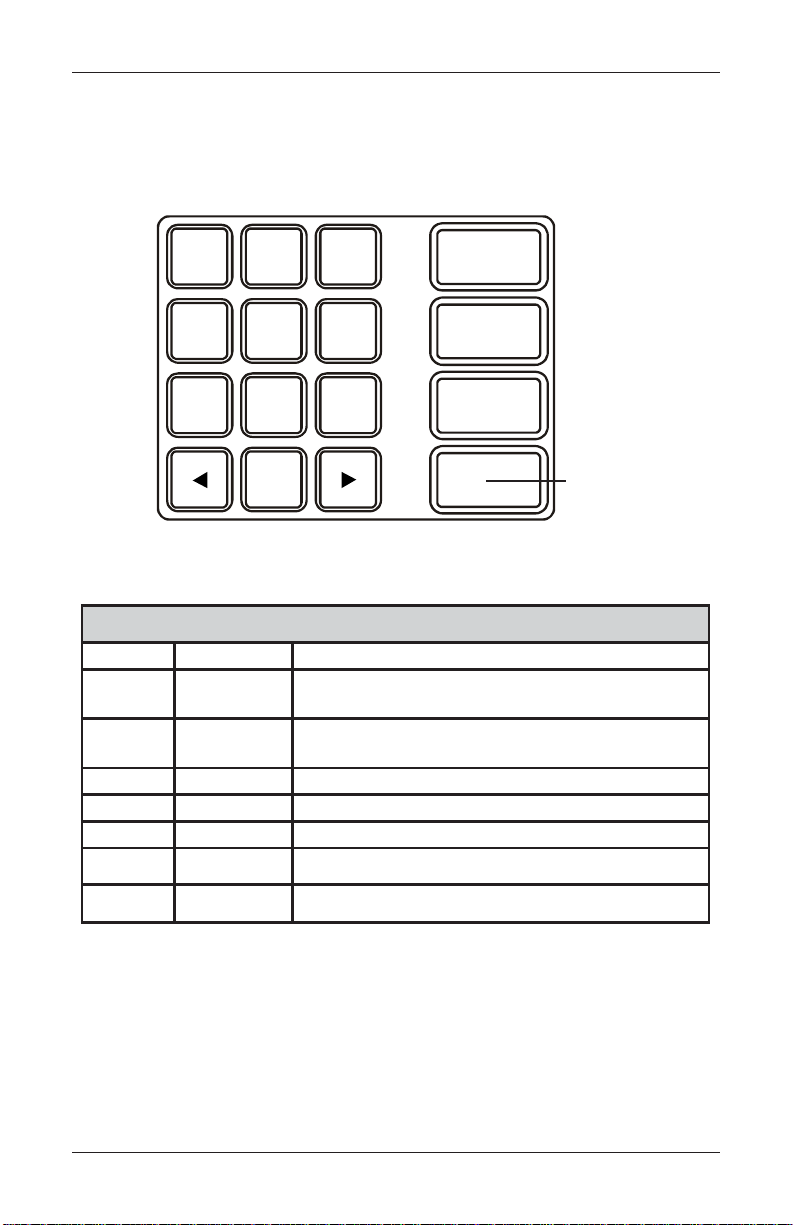
Keypad Operation
See Figure 2-2 and T able 2-1. The main keypad consists of 10 alphanumeric keys,
two arrow keys, and four large control keys, all located in a 16-key group beneath the
LCD display . The table lists the keys and their functions.
123
QZ ABC DEF
ENTER
456
GHI JKL MNO
CLEAR
789
PRS TUV WXY
CANCEL
0
Fig. 2-2. Alphanumeric keypad
YEKPAMDRAOBYEKNOITCA
worrAtfeL
worrAthgiR
retnEretnE .nottubdetcelesasesserprogolaidehtno"retnE"stceleS
lecnaCepacsE.golaidehtno"lecnaC"stceleS
raelCBAT .enilwenatresnilliw,sexobtxetenil-itlumroF.golaidehtnodleiftxenotevoM
yeKLRTC
)yeKknalB(
9-09-0
pUroworrAtfeL
worrA
roworrAthgiR
worrAnwoD
ecapS
.lortnoctsilanipusevoM-
.lortnoctsilaninwodsevoM-
.nottubsucofehtstceleS-
CTRL Key
PAMDRAOBYEK0005TF-1-2ELBAT
.lortnocsuoiverpehtotsucofegnahC-
.lortnoctxenehtotsucofegnahC-
.nottuboidarroxobkcehcaselggoT-
.noitpoxobgolaiddeificepsehttceleS-
.)sexobtidednaobmocrof(dleiftnerrucnikcabllorcS-
.)sexobtidednaobmocrof(dleiftnerrucnidrawrofllorcS-
.retcarahcciremundeificepsehtyalpsidlliwxobtidenaedisninehW-
Table 2-1. Keyboard map.
15
Page 36

MODEL FT5000 USER MANUAL
ON-SCREEN KEYPAD OPERATION
T o enter text characters into the dialog boxes that are displayed by the Management Functions, press the F8 key to display the screen keyboard. Use the keys described below to
navigate and enter required data.
(see Figure 2-3)
• The arrow keys (left and right), the 8 key (Up), and the 0 key (Down) navigate the
keyboard.
• Press the ENTER key to select the highlighted key entry.
• Press the CTRL key to switch between upper and lower case characters.
• Press the CANCEL key to Exit the keyboard.
• Press the CLEAR key for the Backspace operation.
• Press the 1 key to reposition the keyboard to another location on the display.
• Press the 2 key to positon the cursor on a new line.
Figure 2-3. On-screen keyboard.
SCREEN FUNCTION KEYS.
Refer to Figure 2-4. The eight keys, 4 on each side of the LCD, are called screen
function keys. They are used in the selection of screen options that can appear
along the right and left side of the display. These keys are designated F1 through F8.
A screen function key is only active when a corresponding function or menu option
is present next to that key .
Figure 2-4.
Screen function
keys
F1
F2
F3
F4
16
F5
F6
F7
F8
Page 37

BASIC OPERATION
Menu-Based Operation
The terminal operates as a menu driven system. Messages and menu options presented on the LCD display screen guide the user’s actions. The desired menu option
is selected by pressing one of the screen keys located to the left and right of the
display. For the purpose of security, many screens timeout after a preset time interval, usually 30 seconds. The timeout length may vary depending on the function
being performed.
When a screen timeout occurs, a screen is presented which asks the user if more
time is needed. If the user chooses NO, the Customer Welcome screen will be
presented. If YES is chosen, the user is returned to the function that was active prior
to the timeout. If the user does not make a selection within an additional 30-second
countdown period, the terminal will automatically go to the Customer Welcome
screen.
Shortly after the unit is turned on, the top menu will be displayed. An example top
menu is shown in Figure 2-5. From the top menu, you can either:
1.) Activate the terminal to perform customer transactions by pressing the key next
to Customer Transactions.
2.) Enter the terminal system management area by pressing the key next to
Management Functions.
If you do not select a menu choice within 30 seconds, the terminal will automatically
default to the Customer W elcome screen (a benefit of this feature is that in the event
of a power interruption the terminal will automatically begin accepting customer
transactions shortly after power is restored).
Fig. 2-5. Top menu.
17
Page 38

MODEL FT5000 USER MANUAL
Accessing Management Functions
1. At the Customer screen (Figure 2-6), press and hold down the <CTRL> key;
while holding down the <CTRL> key, press the <1> key . Release both keys. The
password entry prompt appears. (Figure 2-7)
2. At the password entry screen, enter the Master or User password.
Fig. 2-7. Password entry dialog.
Fig. 2-6. Customer screen.
To access Management Functions, you must enter an appropriate password in the
dialog box that appears.
The password will consist of a 2-digit ID code and a password of 4-12 digits; for
example, 051234 could be a password entry consisting of an ID code of 05 and a
password of 1234. Press the Enter button to accept the password entry or Cancel to
exit.
When a valid password is entered, the Management Functions main menu will be
displayed, as shown in Figure 2-8:
Fig. 2-8. Management Function main menu
18
Page 39

BASIC OPERATION
DEF AULT MASTER PASSWORD
The default Master user ID is “00” and the password is “1234”. T o enter Management
Functions as the Master user, enter “001234” and press “Enter”.
CHANGE THE MASTER P ASSWORD IMMEDIATEL Y T O PREVENT UNAUTHORIZED ACCESS T O THE A TM! SEE CONFIGURATION MANUAL
FOR PROCEDURES ON CHANGING THE MASTER P ASSWORD AND
OTHER P ASSWORD MANAGEMENT PROCEDURES.
Once you have entered the Management Functions menu, you may perform any of the
functions allowed by the type of password used.
Introduction
This section sumarizes the actions involved in typical customer transactions. In
addition, the voice-enabled transactions feature is described.
Customer T ransactions
A customer begins a transaction by selecting a service from the Customer screen
options ( PaySpot™, CashWorks™, Western Union® or ATM- Get Cash Now).
They insert their ATM card into the card reader of the terminal. The card must be
inserted so that the magnetic stripe can be scanned by the card reader’s sensor. If
the customer inserts the card incorrectly, a warning message will be displayed,
accompanied by several beeps to get their attention.
If there is a problem reading a card, make sure the customer is inserting the card
correctly. Most problems are the result of inserting the card incorrectly.
Once the card has been read in successfully, a surchar ge message, if applicable, may
be displayed (the surcharge message may be displayed at the end of the customer’s
transaction selection). The customer must then enter his secret Personal Identification Number, or PIN code. Once the PIN has been entered, the transaction type and
account are selected and the desired amount of the transaction, if needed. The
transaction will be processed, typically in a matter of seconds.
If the transaction was processed successfully, the customer is prompted to retrieve
the requested cash (for withdrawal transactions) and/or the applicable transaction
receipt, as needed. If the transaction was declined, a short receipt indicating the
problem is printed.
19
Page 40

MODEL FT5000 USER MANUAL
V oice-Enabled Transactions
The terminal provides voice feedback via an integrated output jack, enabling sightimpaired users to plug in a set of headphones and receive spoken instructions to
assist them in using the ATM. Figure 2-9, headphone jack location, shows the
location of the headhone jack on the FT5000.
Fig. 2-9. Headphone jack location.
Raised symbols helps a user locate the headphone jack. The A TM will automatically
detect when a headphone has been plugged into the jack, and will immediately
switch into voice mode. Initially, a brief spoken tutorial will orientate the customer to
the ATM control panel interface. Once the customer begins a transaction, spoken
prompts will provide feedback and guide the customer through the successful
accomplishment of the transaction.
20
Page 41

SECTION 3
INITIAL SETUP
21
Page 42

MODEL FT5000 USER MANUAL
Parameter Categories
There are a number of setup parameters that must be configured when an ATM
is installed. Generally speaking, these parameters can be grouped into the fol-
lowing major categories.
Communications
Security
Surcharging
Currency Settings
Cassette Setup
T ransactions
Receipts
Coupons
Each area consists of one or more individual parameters. In terms of ATM operation,
the importance level of individual parameters within a category can be described as
Critical, Required, Important, or User-Defined.
Languages
Messages
Ad Screens
Date/Time Settings
Status Monitoring
Close
User Interface
Options
22
Page 43

INITIAL SETUP
Parameter Importance Levels
Critical
The parameters with this importance level are primarily those that represent the
minimum number of parameters that must be correctly configured in order to process
transactions. In addition, because of the importance of protecting access to the
A TM Management Functions, the access password parameters are also included in
this category . The primary parameters in this category include various communica-
tions and security (including access password) parameters.
Required
These parameters further satisfy your transaction processor’s setup or operational
requirements. Parameters in this area define the ability of your ATM to offer various
types of transactions, to correctly present those transactions to the customer and to
accurately record those transactions. Surcharge, Cassette Setup, and Account/
Transaction parameters fall into this category.
Important
These parameters are used to manage transaction activity record-keeping, enable remote monitoring of ATM operation, and to ensure receipts and other
records are accurately annotated with the correct date and time. Status Monitor-
ing, Close and Date/Time parameters are included in this category .
User-Defined
These parameters are configured at your discretion, and are used to customize
the appearance and functionality of the ATM to meet the unique language
needs of your intended customers, adjust user interface appearance, satisfy
advertising or promotional requirements, or meet other locale-specific requirements. The management of optional features is also included in this area. Languages, Receipts, Coupons, Messages, Ads/Graphics, and More Options pa-
rameters fall into this category.
NOTE: The importance-level of individual parameters as described in this manual is
provided as a general guide to assist you in understanding and prioritizing the setup
requirements of your ATM. If, after evaluating your unique requirements, you feel
that a parameter is more (or less) important to your particular needs, you are free to
treat that parameter accordingly.
23
Page 44

MODEL FT5000 USER MANUAL
Setup Parameters
T able 3-1, Significance Levels, correlates each Management Functions area to the
significance levels of parameters in that area.
NOTE: The significance level of individual parameters as described in this manual is
provided as a general guide to assist you in understanding and prioritizing the setup
requirements of your ATM. If, after evaluating your unique requirements, you feel
that a parameter is more (or less) important to your particular needs, you are free to
treat that parameter accordingly .
T ables 3-2 through 3-5 list Critical, Required, Important, and User-Defined parameters, respectively . Each table lists the applicable Management Function area, Func-
tion option, Parameter name, and Factory default value for each parameter.
IN T ABLE 3-2, CRITICAL SETUP PARAMETERS, THE NAMES
OF THOSE P ARAMETERS THAT ARE TYPICALLY THE MINIMUM NUMBER REQUIRED IN ORDER TO PERFORM A
TRANSACTION HA VE BEEN HIGHLIGHTED. CHECK WITH
YOUR TRANSACTION PROCESSOR FOR YOUR SPECIFIC
REQUIREMENTS!
IMPORTANT: Although many of the ATM’s parameters have been set at the
factory , it is important to verify that the settings are appropriate for your needs.
Change the factory default values as necessary to reflect the actual settings you
require.
24
Page 45

INITIAL SETUP
SLEVELECNACIFINGIS-1-3ELBAT
AERASNOITCNUFTNEMEGANAMLACITIRCDERIUQERTNATROPMIDENIFED-RESU
1EGAUGNAL X
2SRETEMARAPMETSYSX X
3SNOPUOC X
4SEGASSEMXX
5SRETEMARAPLARENEGXXXX
6SCIHPARG/SDA X
7SNEERCSLANOITPOXX
8SNOTTUBNEERCSLANOITPOXX
9NOITACINUMMOCX X
01SCITSONGAIDX
11ECNANETNIAMDROWSSAPX
21TNEMEGANAMYEKX
31SRETEMARAPETTESSACXX
41SNOITCNUFESOLCXX
51STNUOMALAWARDHTIWX
61NOITARUGIFNOCETONX
71SEITREPORPEGRAHCRUSX
81EMIT/ETAD X
91TCENNOCNOTIRT X
02RETNIRP X
12ENOHPDIAPERP X
22GNIHSACKCEHC X
32REFSNARTYENOM X
25
Page 46

MODEL FT5000 USER MANUAL
SRETEMARAPPUTESLACITIRC-2-3ELBAT
TNEMEGANAM
AERASNOITCNUF
1
2
3
4
5
6
7
8
9
01
11
21
31
41
51
61
71
81
91
SCITSONGAIDMEDOM
ECNANETNIAMDROWSSAPDROWSAPRESUEGNAHC 432100
ECNANETNIAMDROWSSAPSSECCARESUYFIDOM*
ECNANETNIAMDROWSSAPRESUDDAA/N
ECNANETNIAMDROWSSAPRESUEVOMERA/N
SRETEMARAPMETSYSELIFNEERCSTCELES*
NOITARUGIFNOCLANIMRETSRETEMARAPLARENEG
NOITARUGIFNOCLANIMRETPUTESETTESSAC
NOITARUGIFNOCLANIMRETNOITACINUMMOC
NOITARUGIFNOCLANIMRETNOITACINUMMOCREBMUNPUKCABENON
NOITARUGIFNOCLANIMRETNOITACINUMMOCGNI-CAMELBANE*
NOITARUGIFNOCLANIMRETNOITACINUMMOC
NOITARUGIFNOCLANIMRETNOITACINUMMOC
`NOITARUGIFNOCLANIMRETNOITACINUMMOC)KAPATAD(REBMUNAUN*
TNEMEGANAMYEKYEKRETSAMCAMRETNE*
TNEMEGANAMYEK
TNEMEGANAMYEKSYEKRETSAMTCEJNI*
TNEMEGANAMYEK
TNEMEGANAMYEK
NOITPONOITCNUFEMANRETEMARAP
MEDOMERUGIFNOC
REBMUNLANIMRET
SRETEMARAPETTESSAC
REBMUNYRAMIRP
SNOITACINUMMOC
LOCOTORP
SNOITACINUMMOC
EGASSEM
YEKRETSAMNIPRETNE*
GNIKROWDAOLNWOD
SYEK
STIGIDKCEHC*
YROTCAF
TLUAFED
*
ENON
00.0$
ENON
*
*
*
26
Page 47

INITIAL SETUP
SRETEMARAPPUTESDERIUQER-3-3ELBAT
TNEMEGANAM
AERASNOITCNUF
NOITPONOITCNUFEMANRETEMARAP
YROTCAF
TLUAFED
1
2
3
4
5
6
7
8
9
01
11
21
31
41
51
61
71
81
91
02
12
22
32
42
52
62
72
82
92
ESOLCLANIMRET
SNOITCNUF
NOITARUGIFNOCLANIMRETSRETEMARAPLARENEG
NOITARUGIFNOCLANIMRETSRETEMARAPLARENEG
NOITARUGIFNOCLANIMRETSEGASSEMLANIMRETRENWOEGRAHCRUS*
NOITARUGIFNOCLANIMRETPUTESETTESSACHSACMUMIXAM00.005$
NOITARUGIFNOCLANIMRETPUTESETTESSACHSAC-NONMUMIXAM00.0$
NOITARUGIFNOCLANIMRETPUTESETTESSACSTNUOMADEDNETXEDELBASID
NOITARUGIFNOCLANIMRETPUTESETTESSACHSACTSAF*
SCITSONGAID
NOITARUGIFNOCLANIMRET
NOITARUGIFNOCLANIMRET
NOITARUGIFNOCLANIMRET
NOITARUGIFNOCLANIMRET
NOITARUGIFNOCLANIMRET
NOITARUGIFNOCLANIMRET
NOITARUGIFNOCLANIMRET
NOITARUGIFNOCLANIMRET
NOITARUGIFNOCLANIMRETSEITREPORPEGRAHCRUSEGRAHCRUSELBANEDELBASID
NOITARUGIFNOCLANIMRETSEITREPORPEGRAHCRUSTNUOMAEGRAHCRUS00.0$
NOITARUGIFNOCLANIMRETSEITREPORPEGRAHCRUSTNECREPEGRAHCRUS%0
NOITARUGIFNOCLANIMRETSEITREPORPEGRAHCRUSRETAERG/RESSELRESSEL
NOITARUGIFNOCLANIMRETSEITREPORPEGRAHCRUSDETSILsOSIWOLLA*
NOITARUGIFNOCLANIMRETSEITREPORPEGRAHCRUSsOSIWENDDAENON
NOITARUGIFNOCLANIMRETSNEERCSLANOITPONOITPOEGRAHCRUSGNINNIGEB
NOITARUGIFNOCLANIMRETSNEERCSLANOITPONOITPOTPIECER*
NOITARUGIFNOCLANIMRETSNEERCSLANOITPO
NOITARUGIFNOCLANIMRET
NOITARUGIFNOCLANIMRET
NOITARUGIFNOCLANIMRET
ESOLCETTESSACYTITNAUQETTESSAC0
NOITCASNARTTLUAFED
EPYT
TNUOCCATLUAFED
EPYT
RESNEPSID
)SRETEMARAPETTESSAC(
PUTESETTESSAC
)SRETEMARAPETTESSAC(
PUTESETTESSAC
)SRETEMARAPETTESSAC(
PUTESETTESSAC
)SRETEMARAPETTESSAC(
PUTESETTESSAC
)SRETEMARAPETTESSAC(
PUTESETTESSAC
)SRETEMARAPETTESSAC(
PUTESETTESSAC
)SRETEMARAPETTESSAC(
PUTESETTESSAC
)SRETEMARAPETTESSAC(
PUTESETTESSAC
)SRETEMARAPETTESSAC(
NEERCSLANOITPO
SNOTTUB
NEERCSLANOITPO
SNOTTUB
NEERCSLANOITPO
SNOTTUB
LLIBNRAELER
SSENKCIHT
EPYTTNEMUCODHSAC
METIHSAC-NON
NOITPIRCSED
METIYRADNOCES
NOITPIRCSED
NOITARUGIFNOCETON
)HTDIWLLIB(
NOITARUGIFNOCETON
)HTGNELLLIB(
NOITARUGIFNOCETON
)EULAV(
NOITARUGIFNOCETON
)TNAIRAV(
NOITARUGIFNOCETON
)EDOC(
NOITCASNART/TNUOCCA
NOITCELES
NOITCELESTNUOCCA*
NOITCASNART
NOITCELES
NOITCELESHSACTSAF*
*
*
*
ENON
ENON
*
*
*
*
*
*
*
27
Page 48

MODEL FT5000 USER MANUAL
SRETEMARAPPUTESTNATROPMI-4-3ELBAT
TNEMEGANAM
AERASNOITCNUF
1
2
3
4
5
6
7
8
9
01
11
21
31
41
51
61
71
81
91
02
12
22
32
42
52
62
72
ESOLCLANIMRET
SNOITCNUF
ESOLCLANIMRET
SNOITCNUF
SCITSONGAIDRETNIRPERUGIFNOC*
SRETEMARAPMETSYSEMITDNAETADEMIT/ETADTES*
SRETEMARAPMETSYSSGNITTESLANOIGERA/N
NOITARUGIFNOCLANIMRETSRETEMARAPLARENEGGNIROTINOMSUTATSDELBASID
NOITARUGIFNOCLANIMRETSRETEMARAPLARENEGEGASSEMTAEBTRAEH*
NOITARUGIFNOCLANIMRETSRETEMARAPLARENEGDOIREPYALED*
NOITARUGIFNOCLANIMRETNOITACINUMMOCLAIDERPDELBASID
NOITARUGIFNOCLANIMRETNOITACINUMMOCREDAEHNOITACINUMMOCDELBASID
NOITARUGIFNOCLANIMRETNOITACINUMMOC
NOITARUGIFNOCLANIMRETNOITACINUMMOC
NOITARUGIFNOCLANIMRETNOITACINUMMOCSTPMETTALASREVERDELBASID
NOITARUGIFNOCLANIMRETNOITACINUMMOC
NOITARUGIFNOCLANIMRETTCENNOCNOTIRTREBMUNYRAMIRPENON
NOITARUGIFNOCLANIMRETTCENNOCNOTIRTREBMUNPUKCABENON
NOITARUGIFNOCLANIMRETTCENNOCNOTIRTYRAMIRPROTINOMMRALAENON
NOITARUGIFNOCLANIMRETTCENNOCNOTIRTPUKCABROTINOMMRALAENON
NOITARUGIFNOCLANIMRETTCENNOCNOTIRTSEIRTERXAM*
NOITARUGIFNOCLANIMRETTCENNOCNOTIRTYALEDLAIDER*
NOITARUGIFNOCLANIMRETTCENNOCNOTIRTTCENNOCNOTIRTELBANEDELBASID
NOITARUGIFNOCLANIMRETTCENNOCNOTIRTKCABLLACELBANEDELBANE
NOITARUGIFNOCLANIMRETTCENNOCNOTIRT
NOITARUGIFNOCLANIMRETTCENNOCNOTIRTEMIT*
NOITARUGIFNOCLANIMRETTCENNOCNOTIRT
NOITARUGIFNOCLANIMRETTCENNOCNOTIRTHSACWOLTALLACELBANEDELBASID
NOITARUGIFNOCLANIMRETTCENNOCNOTIRTEDOCSSECCAWENRETNE*
NOITPONOITCNUFRETEMARAP
ESOLCELUDEHCS DELBASID
SLATOTLANIMRETDNES DELBASID
ECNEUQESETYB-21ESU
REBMUN
TNETSISREPELBANE
SLASREVER
ROFSLASREVERELBANE
SRORRELOCOTORP
DELUDEHCSELBANE
SLLACLANRUOJ
REBMUNTALLACELBANE
SDROCERLANRUOJFO
YROTCAF
TLUAFED
*
DELBASID
DELBASID
DELBASID
DELBASID
28
Page 49

INITIAL SETUP
SRETEMARAPPUTESDENIFED-RESU-5-3ELBAT
TNEMEGANAM
SAERASNOITCNUF
1
2
3
4
5
6
7
8
9
01
11
21
31
41
51
61
71
81
91
02
12
22
32
42
52
62
EGAUGNALHSINAPS/HCNERF/HSILGNE*
SRETEMARAPMETSYSEMULOV*
SRETEMARAPMETSYSTOOBERELUDEHCS
NOITARUGIFNOCLANIMRETSRETEMARAPLARENEG
NOITARUGIFNOCLANIMRETSNOPUOCNOPUOC*
NOITARUGIFNOCLANIMRETSNOPUOCTPMORP*
NOITARUGIFNOCLANIMRETSNOPUOCLEVELMUMINIM*
NOITARUGIFNOCLANIMRETSNOPUOCLEVELMUMIXAM*
NOITARUGIFNOCLANIMRETSNOPUOCMODNAR*
NOITARUGIFNOCLANIMRETSNOPUOCEGASSEM*
NOITARUGIFNOCLANIMRETSNOPUOCTUOYAL*
NOITARUGIFNOCLANIMRETSNOPUOCCIHPARG*
NOITARUGIFNOCLANIMRETSNOPUOCTNIRP*
NOITARUGIFNOCLANIMRETSNOPUOCETTESSAC*
NOITARUGIFNOCLANIMRETSNOPUOCTNUOC*
NOITARUGIFNOCLANIMRETSEGASSEMLANIMRETEGASSEMEMOCLEW*
NOITARUGIFNOCLANIMRETSEGASSEMLANIMRETEGASSEMEROTS*
NOITARUGIFNOCLANIMRETSEGASSEMLANIMRETEGASSEMGNITEKRAM*
NOITARUGIFNOCLANIMRETSEGASSEMLANIMRETEGASSEMTIXE*
NOITARUGIFNOCLANIMRETSEGASSEMLANIMRET
NOITARUGIFNOCLANIMRETSEGASSEMLANIMRET
NOITARUGIFNOCLANIMRETSCIHPARG/SDAWENDDA*
NOITARUGIFNOCLANIMRET
SNOITPOEROMENOHPDIAPERP*
SNOITPOEROMGNIHSACKCEHC*
SNOITPOEROMREFSNARTYENOM*
NEERCSLANOITPO
SNOTTUB
NOITPONOITCNUFRETEMARAP
ELBASID/ELBANE
TCELESYAD/TESEMIT
EGAUGNALTLUAFED
)SNEERCSREMOTSUC(
RENWOLANIMRET
EGASSEM
REKCITSWEN
EGASSEM
ESAHCRUP
SNOITCELES
YROTCAF
TLUAFED
*
*
*
*
*
29
Page 50

MODEL FT5000 USER MANUAL
THIS PAGE INTENTIONALL Y LEFT BLANK
30
Page 51

SECTION 4
CURRENCY HANDLING
31
Page 52

MODEL FT5000 USER MANUAL
Introduction
The purpose of this section of the manual is
to describe the procedures for: (1) removing
and replacing note cassettes, (2) loading cassettes, and (3) removing and replacing the
reject notes (as applicable). Information
concerning note handling and quality issues
are explained where appropriate.
DISPENSING MECHANISM
The FT5000 ATM uses an NMD-100, friction-feed dispensing mechanism
and deliver notes and other media to
the customer. The mechanism is located
in the lower security container of the
unit. It holds multiple note cassettes and
a single reject cassette.
Under software control, the dispensing
mechanism delivers the appropriate
number of notes from the note cassettes
to fulfill a customer’s withdrawal request. The purpose of the reject cassette is to accept and hold notes that
have been transferred from the note cassettes but not dispensed. Some situations that could cause the mechanism
to reject notes are:
to store
The mechanism is able to reject single
notes or bundles. A bundle reject occurs
when more than one note is rejected at
the same time. There are two compartments within the reject cassette to keep
notes in these two categories separated.
The top compartment within the cassette
can hold a maximum of 250 bundle-notes;
the lower compartment can hold up to
100 single-note rejects.
IMPORTANT! The first time the dispenser is set up, or if a new note cassette is installed, the mechanism will enter a learning mode, during which it will
reject 7-15 notes as it learns the thickness of the currency or other media. W ith
multiple cassettes installed, the number
of test rejects could almost fill the singlenote compartment of the reject cassette.
In such cases, it is recommended that
you remove any rejected notes from the
unit before placing the ATMback into
service.
**WARNING**
DO NOT RECYCLE REJECTED
NOTES INTO A CASSETTE!
Doing so could cause more rejects
and/or currency jams.
• Multiple notes stuck together
• Note width too short or long
• Notes skewed in feed path
• Notes too close together in
feed path
• Notes not claimed by customer (after a preset timeout
the mechanism will retract the
notes and send them to the
reject cassette).
NOTE CONDITION
The number of rejects can be directly
influenced by the technique used to
load the cassettes and the quality of
the currency. Notes loaded into the
mechanism cassettes must be in “fit”
condition if a high level of performance
(low reject and failure rate) is expected
from the unit. “Fit” notes are defined
as those that do not possess any of
the defects listed here:
32
Page 53

CURRENCYHANDLING
USED NOTES
• Adhesive or “sticky” substances on the surface of the
paper.
• T ears extending more than
1/2” from the edge of the currency .
• T ears, holes, or missing sections in the body of the currency .
• Tape on the surface of the cur rency used for repairing,
patching, or any other
purpose.
• Staples, pins, or any other for
eign body attached to the
notes.
• Corner folds of a size greater
than 1/2” on either axis.
• T wo or more notes joined by
any means.
• Excessively crumpled or
crinkled.
PREPARING NOTES
Use the following procedures to prepare notes before inserting them into a
note cassette.
USED NOTES
• Remove the band around each
bundle of notes.
• Remove foreign objects (e.g.
pins, paper clips, crumbs, etc).
• Remove torn or very worn
notes.
• Straighten any folded notes.
NEW OR UNCIRCULATED NOTES
• All the conditions listed for
used notes.
• Excessive bowing due to con
ditions of packing and storing.
• New or uncirculated currency
must be “burst” and fully separated prior to loading into
cassettes.
Figure 4-1. Removing band.
Figure 4-2. Removing torn/worn
notes.
33
Page 54

MODEL FT5000 USER MANUAL
NEW OR UNCIRCULATED NOTES
Remove the band around each
bundle of notes. Separate the
notes from each other by:
• Striking the bundle hard
against the edge of a table
or similar object.
• Flipping through each
bundle of notes in both
directions at each end.
• Using a note counter.
REMOVING NOTE CASSETTES
1. Unlock the cassettes, using the
Cassette Close procedure in
Section 5, Management
Functions.
2. Open the electronic lock on the
security container door and open
the door to gain access to the
dispensing mechanism.
Figure 4-3. Flipping bundle ends.
3. To remove the selected note
cassette, grasp the cassette
handle with one hand while
holding the mechanism in place
with the other hand (See Figures
4-5a and 4-5b). Pull the cassette
out slightly. Place one hand
underneath to support the
cassette as you slide it com-
pletely out of the unit.
Figure 4-4. Security container open.
34
Page 55

CURRENCYHANDLING
***CAUTION***
The “throat” assembly on the mechanism is not a load bearing structure!
Do not grasp or apply any pressure
to the throat.
Figure 4-5a. Cassette removal. Figure 4-5b. Cassette removal.
4. Continue to support the bottom of
the cassette to keep it level as you
place it on a table or other flat surface. If the cassette has a loading
arm, fold it down, which will raise
the rear of the cassette and allow
gravity to help keep the notes neatly
stacked during the loading pro-
cess. (Figure 4-6)
Figure 4-6. Cassette w/loading
OPENING NOTE CASSETTES
arm down.
1. Insert the key into the cassette
lock. (Figure 4-7) T o unlock the
cassette, apply inward pressure
on the key while turning it
clockwise to the stop position
(approximately a quarter-turn).
Open the cassette by simultaneously pressing the release
button and lifting the lid. Flip the
lid back fully, allowing it to rest
on the table or other flat surface.
(Figure 4-8)
Figure 4-7. Key inserted.
35
Page 56
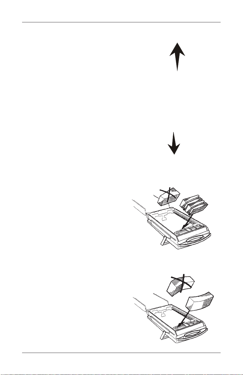
MODEL FT5000 USER MANUAL
2. Move the pusher plate to the rear
of the cassette (toward the handle).
Ensure the pusher plate is fully
back. It should stay in this posi-
tion. (Figure 4-9)
LOADING NOTE CASSETTES
1. Load the cassette with currency.
The shape of some notes may be
affected by conditions of storage
or bundling, preventing them from
forming neat even piles. If not corrected, such conditions may cause
notes to be rejected by the dispensing mechanism. To compensate for the most common conditions of slanting or cupped note
piles, follow the directions given
here. Notes with no apparent shape
problems are referred to as “com-
mon” notes.
• Slanting pile
Figure 4-8. Release button.
Figure 4-9. Lid open and pusher
plate back.
To avoid dispensing problems caused
by a “slanting” pile, put the notes in
neat bundles of no more than ½ to ¾
inches in thickness. Turn every other
bundle around to minimize slanting of
the pile. (Figure 4-10)
• Cupped bundle
To avoid dispensing problems caused
by cupped bundles, turn all the bundles
with the cupped side towards the dispense opening. (Figure 4-11)
• Common notes
Place the prepared bundles in the cassette.
Figure 4-10. Slanted piles.
Figure 4-11. Cupped bundle.
36
Page 57

CURRENCYHANDLING
2. Level the note pile. Compress the
notepile slightly by hand. Single
notes must not protrude from the
bundle. (Figure 4-12)
3. Move the pusher plate against the
notes with just enough pressure
to hold the notes in the correct position when closing the lid and inserting the cassette into the mechanism. (Figure 4-13)
4. Move the white plastic levers
(Pawls) on the pusher plate to their
fully extended position. This will
allow the pusher plate to retract
and releave pressure from the note
stack when an unlock command is
sent to the dispenser . (Fig. 4-14)
5. Close the cassette lid. Fold the lid
down to its locked position. The
release button should “pop” out,
allowing the lid to mate cleanly with
the body of the cassette. You may
need to “tap” the lid firmly along
the front edge to achieve this. Turn
the key counter-clockwise to lock
the cassette. (Figure 4-15)
Figure 4-12. Leveling note pile.
Figure 4-13. Moving pusher plate
against notes.
INSTALLING NOTE CASSETTES
Using the reverse of the steps used to
remove the note cassette from the
mechanism, slide the note cassette into
its slot in the mechanism. Keep the cassette level as you load it, and make sure
the cassette is fully inserted. Once all
cassettes have been filled and reinserted, they are ready to be Locked into
position following the Cassette Close
function prompts. (see Section 5, Management Functions, for the appropriate
procedure).
Figure 4-14. “Pawls” extended.
Figure 4-15. Closing lid.
37
Page 58

MODEL FT5000 USER MANUAL
REMOVING THE REJECT
CASSETTE
1. Unlock the cassettes, using the
Cassette Close procedure in Section 5, Management Functions.
2. Open the outer fascia panel of the
security container, using the key
lock on the front of the panel. Open
the electronic lock on the security
container door and open the door
to gain access to the dispensing
mechanism.
3. To remove the reject vault, (top
channel) grasp the cassette handle
with one hand while holding the
mechanism in place with the other
hand. Pull the cassette out slightly .
Place one hand underneath to support the cassette as you slide it completely out of the unit. Place it on a
level surface. (Figures 4-16a and 4-
16b)
**IMPORT ANT**
If you remove the reject vault with
power applied, the terminal will sense
this and automatically reset the rejected note count to ZERO. Therefore, to ensure an accurate rejected
note count NEVER REMOVE THE
REJECT V AULT WITH POWER APPLIED WITHOUT CHECKING FOR
AND REMOVING ANY REJECTED
NOTES.
Figure 4-16a. Removing the reject
vault.
Figure 4-16b. Reject vault ready to
open.
38
Page 59

CURRENCYHANDLING
OPENING THE REJECT VAULT
1. Insert the key into the vault lock.
T o unlock the vault, apply inward
pressure on the key while turning
it clockwise to the stop position
(approximately a quarter-turn).
Open the vault by simultaneously
pressing the release button and lifting the lid. Flip the lid back fully.
(Figures 4-17 and 4-18)
2. The reject vault is now open for
collecting any rejected bundle
notes. These will be present in the
folding tray. After retrieving any rejected bundle notes, lift the folding
tray and check underneath for any
rejected single notes. (Figures 4-19
and 4-20)
Figure 4-17. Key inserted.
Figure 4-18. Opening lid.
3. After removing any rejected notes,
close the vault lid. Fold the lid
down to its locked position. The
release button should “pop” out,
allowing the lid to mate cleanly with
the body of the cassette. Turn the
key counter-clockwise to lock the
vault.
INST ALLING THE REJECT
VAULT
Using the reverse of the steps taken to
remove the reject vault, slide the vault
back into its slot in the mechanism.
Make sure the vault is fully inserted.
Ensure the note cassettes are Locked
and In Service using the Cassette Close
procedures in Section 5, Management
Functions.
Figure 4-19. Bundle reject tray.
Figure 4-20. Single reject
compartment.
39
Page 60

MODEL FT5000 USER MANUAL
V erify Operation
1. Close and lock the security cabinet.
2. Verify the cassettes are Locked and In
Service.
3. In Management Functions, select
Diagnostics, then Dispenser.
4. Select the Test Dispense option.
Select either individual cassettes
that are installed (“A”, “B”, “C”,or
“D”) or “All Cassettes ”. A prompt
appears asking how many notes to
dispense. (Figure 4-21) The Test
Dispense operation will start.
5. The Test Dispense command
instructs the dispenser to
dispense, minimum, one note from
each installed and operational
cassette into the reject vault. This
test exercises the dispenser without
sending notes to the exit.
Figure 4-21. Enter # of notes.
6. After completion of the Test
Dispense, the following prompt is
displayed. (Figure 4-22) - “Test
Dispense Completed Successfully
- Dispense Count , A: (# of notes),
B: #, etc
**IMPORTANT**
Ensure the MUL TIPLE AMOUNT parameter matches the denomination
of currency in each Note Cassette!
See the procedure for using the
MUL TIPLE AMOUNT function to set
this parameter, in Section 5, Management Functions.
Figure 4-22.
40
Page 61

SECTION 5
MANAGEMENT FUNCTIONS
41
Page 62

MODEL FT5000 USER MANUAL
Introduction
This section describes the Management Functions available for controlling the
ATM. When the Customer Welcome screen is displayed, you can access the
Management Functions menu by following the procedure described next.
Accessing the Management Functions Menu
1. Press and hold down the <CTRL> key; while holding down the <CTRL> key ,
press the <1> key. Release both keys. After a moment the top menu will be
displayed.
2. At the top menu (see Figure 5-1below), select MANAGEMENT FUNCTIONS
by pressing the F7 screen key (next to Management Function option).
F1
F2
F3
F4
Figure 5-1. Location of the F7 key (highlighted by the circle).
3. Enter the Master or User password at the password entry display (see Figure 5-
2 below).
Figure 5-2. Enter your
Master or User password at the Management
Functions screen.
42
F5
F6
F7
F8
Page 63

MANAGEMENT FUNCTIONS
T o access Management Functions, you must enter an appropriate password in the
dialog box that appears when the Management Functions option is selected. The
password will consist of a 2-digit ID code and a password of 4-12 digits; for example,
051234 could be a password entry consisting of an ID code of 05 and a password of
1234. Press the Enter button to accept the entry or Cancel to exit. When a valid
password is entered, the Main Menu screen will be displayed. (Figure 5-3)
DEF AULT MASTER PASSWORD
The default master user ID is “00” and the password is “1234”.
To enter Management Functions as the master user, enter “001234” and press OK.
CHANGE THE MASTER P ASSWORD IMMEDIATEL Y T O PREVENT UNAUTHORIZED ACCESS TO THE ATM!
Function Availability
Once you have entered the Main Menu, you may perform any of the functions
allowed by the type of password used (access level).
Each Main Menu option description will include the function name, instructions for
accessing the function, a description of the function, and any associated factory
default values.
The Main Menu screen allows the service provider/terminal operator to access the
following management functions:
1. Close Functions. Used to perform Cassette Close, Day Close, Trial Close and
Schedule Close functions.
2. Diagnostics. Used to perform terminal hardware testing, and to view test
results.
3. Electronic Journal. Used to manage the ATM’s journal functions, such as
display/print and clearing actions.
4. Password Maintenance. Used to add, modify, or delete terminal access
privileges.
5. System Parameters. Used to shut down or restart the terminal, to configure
location-specific settings such as time and date, and to adjust the audio
volume.
6. T erminal Configuration. Used to view/edit terminal operating parameters
such as surcharging, customer-screen language selection, communications,
status monitoring, ads/graphics and Triton Connect configuration.
7. Key Management. Used to enter encryption keys, which protect
communcations between the ATM and the transaction processing service
provider.
43
Page 64

MODEL FT5000 USER MANUAL
8. T erminal S tatus. Used to view terminal status reports.
9. Language. Press the 9 key repeatedly to cycle through the available languages.
The current language is displayed in the button caption. When a language is
selected, the ATM uses the language in all Management Functions.
0. More Options. Used to display additional configuration options that may be
available to the user.
Figure 5-3. Main Menu screen.
NOTE
The availability of some Management Functions will depend on such factors as
types of optional hardware installed, user password options, etc. In cases where
a function is not applicable or available, the option will be “grayed out,” or
otherwise disabled. The rest of this section addresses functions the User/Operator may need to perform day-to-day operations.
Management Reports
Many Management Functions, such as Close, Journal and Diagnostic functions,
produce a report summarizing the results of the operation. Most reports are displayed in a Management Report dialog, which you can use to print the report to the
receipt printer, or to save the report to an external memory device.
The buttons on the Management Report dialog let you perform the following actions: (Figure 5-4)
44
Page 65

MANAGEMENT FUNCTIONS
The buttons on the Management Report dialog let you perform the following actions:
(Figure 5-4)
1. Page Up. Scrolls the report up a maximum of one full page.
2. Home. Moves directly to the first page of the report.
3. Print. Sends the report to the terminal receipt printer for hardcopy output.
4. Page Down. Scrolls the report down a maximum of one full page.
5. End. Moves directly to the last page of the report.
6. Save T o File. Saves the report as a text file to an external memory device.
Figure 5-4. Management Report menu.
45
Page 66

MODEL FT5000 USER MANUAL
CLOSE FUNCTIONS
Introduction
Cassette and Day Close reports provide important information about the transactions being performed by your ATM. This information helps you manage the ATM
more effectively .
The ATM’s close functions are accessed through the Management Function’s
T erminal Close Functions menu.
Cassette Close
The Cassette Close report shows current cassette activity, including total notes
dispensed and remaining, and the total value of those notes, since the previous
Cassette Close was performed. This report can help you judge the volume of with-
drawal activity and plan cassette replenishment activities accordingly .
IMPORTANT
• Perform a Cassette Close before replenishing the currency in the cassette.
• Performing a Cassette Close will reset the cassette activity totals to zero (0). The
Enter Cassette Quantity value is also reset to zero.
• After performing a Cassette Close and replenishing the cash in the cassette,
enter the total number of bills loaded in the cassette, using the Enter Cassette
Quantity function.
It is very important that you always enter this value after performing a Cassette
Close! The ATM uses this starting number to calculate the quantity and
(monetary) amount of notes remaining in the cassette after each withdrawal.
Failure to enter the cassette quantity will result in negative-numbered totals
being listed in the Cassette Close report!
• After you enter the cassette quantity, a Trial Cassette Close Report appears
which you can print or save to an external storage device. This is a record of the
beginning cassette balance. The cassette totals will not be cleared.
46
Page 67

MANAGEMENT FUNCTIONS
Day Close
The Day Close report shows the cumulative value of all transactions (withdrawals,
transfers and balance inquiries) performed by the ATM since the previous Day
Close. The report also shows the corresponding host totals, allowing you to com-
pare the ATM totals against the host processor records.
IMPORTANT
• Perform a Day Close once each business day. Because the host processor also
performs a business-day close for the ATM, you should perform the Day Close
at the same time each day, at the time specified by your host processor . This will
help ensure the Day Close report reflects the host’s current business- day
totals for your ATM.
• To help ensure Day Closes are performed at the same time each day you can use
the Schedule Close function, which automatically performs a Day Close each
day, at a time specified by the Change Schedule function.
• The Day Close report shows totals accumulated by the host processor during
the business day, as stated earlier. In some cases, the host processor can make
use of the totals recorded by the ATM. In these cases, you can provide ATM
totals to the host processor during the Day Close, using the Send Terminal
Totals function.
47
Page 68

MODEL FT5000 USER MANUAL
TERMINAL CLOSE FUNCTIONS
FACTORY DEFAULT: N/A
ACCESS INSTRUCTIONS:
1. From the MAIN MENU screen,
select the TERMINAL CLOSE
FUNCTIONS option by pressing the number (1) on the keypad.
DESCRIPTION:
The TERMINAL CLOSE menu allows the terminal operator to perform the following
functions:
1. Schedule Close. Used to enable/disable automatic Day Close.
2. Send Terminal Totals (ON/OFF). Use to enable/disable automatic
transmission of terminal close totals to your transaction processing service
provider. Press this button to cycle the function between ON and OFF.
3. T rial Close. Used to initiate a T rial Day Close.
4. Day Close. Used to initiate a Day Close.
5. Trial Cassette Close. Used to provide a receipt/record of the cassette(s)
balance.
6. Cassette Close Functions. Used to access a menu of cassette close and
configuration functions.
48
Page 69

MANAGEMENT FUNCTIONS
SCHEDULE CLOSE
FACTOR Y DEFAULT: OFF
ACCESS INSTRUCTIONS:
1. From the MAIN MENU screen,
select the TERMINAL CLOSE
FUNCTIONS option by pressing number (1) on the keypad.
2. To access the SCHEDULE
CLOSE function, press the number (1) on the keypad.
DESCRIPTION:
This function allows you to turn ON or OFF the SCHEDULE CLOSE function and to
specify a time of day at which a close operation will be performed.
If the Enable Schedule option is ON, a Day Close will be automatically initiated at the
specified time of day. If the checkbox is checked, the option is ON. If the checkbox is
not checked, the function is OFF . Press the number (1) key to switch the checkbox
between ON (checked) and OFF (not checked).
Use the number (2), (3), (4), and (5) keys to choose the hours, minutes, seconds, and
AM/PM settings at which the scheduled close is to be performed. Pressing a key
repeatedly will cause the associated field to cycle through the available values. The
current time setting appears in a small text window below the time set buttons. Use
the number (6) key to select a specific day of the week (Sunday, Monday , Tuesday ,
etc.), or a a setting of EVERYDA Y, to determine the day(s) of the week to which the
scheduled time applies.
Press Enter to accept the Schedule Close settings and return to the Terminal Close
Functions main dialog window or press Cancel to exit without making any changes.
49
Page 70

MODEL FT5000 USER MANUAL
SEND TERMINAL TOTALS
FACTOR Y DEFAULT: OFF
ACCESS INSTRUCTIONS:
1. From the MAIN MENU screen,
select the TERMINAL CLOSE
FUNCTIONS option by pressing number (1) on the keypad.
2. To change the condition of the
SEND TERMINAL TOTALS
function to ON, press number (2)
on the keypad.
DESCRIPTION:
This function allows you to turn ON or OFF the SEND TERMINAL TOTALS option.
When the option is turned ON, the terminal will send accumulated totals information
to your transaction processing service provider during the day close operation. If
the option is set to OFF, these totals will not be sent.
T erminal totals include the total value of all withdrawal, inquiry, and transfer transactions that have occurred since the last day close operation (see the description of
the Day Close function for additional information).
The current state of the Send T erminal Totals feature is shown as either ON or OFF
in the button label. Press the number (2) on the keypad to toggle the state of the
feature between ON or OFF .
50
Page 71

MANAGEMENT FUNCTIONS
TRIAL CLOSE
FACTORY DEFAULT: N/A
ACCESS INSTRUCTIONS:
1. From the MAIN MENU screen,
select the TERMINAL CLOSE
FUNCTIONS option by pressing number (1) on the keypad.
2. T o display the Management Report that provides the TRIAL
CLOSE information for the A TM,
press number (3) on the keypad.
3. When the TRIAL CLOSE dialog
appears, press the ENTER key.
DESCRIPTION:
The TRIAL CLOSE function is used during the daily close procedure. It does the
same thing as the DAY CLOSE, except that the totals are not cleared.
The report printed by the Trial Close is used to balance your ATM before you
actually balance with your processor. It contains accumulated transaction totals,
obtained from the processor and from the terminal itself.
The report shows the total number of customer transactions (Withdrawals, Inquiries
and Transfers) recorded by the processor and the terminal since the last Day Close
was performed. The two-column format allows the host and terminal totals in each
category to be easily compared. The ‘Settlement $’ value is the host processor ’s
record of the total currency dispensed from the terminal since the last Day Close
was performed.
A call to the processor host computer is required to complete the operation. If the
call to the processor host system is not completed successfully, a warning (***HOST
TOT ALS NOT RECEIVED***) will be printed on the report. The report is displayed
in a Management Report dialog, which you can print to the receipt printer or save to
an external memory device.
51
Page 72

MODEL FT5000 USER MANUAL
DAY CLOSE
FACTORY DEFAULT: N/A
ACCESS INSTRUCTIONS:
1. From the MAIN MENU screen,
select the TERMINAL CLOSE
FUNCTIONS option by pressing number (1) on the keypad.
2. T o display the Management Report that provides the DAY
CLOSE information for the A TM,
press number (4) on the keypad.
3. When the DAY CLOSE dialog
appears, press the ENTER key .
DESCRIPTION:
The DAY CLOSE function is used to complete daily balancing of the ATM with the
processor. The Day Close is performed to clear the totals and switch to the next
business day. This function prints a report summarizing all of the transactions
performed since the last Day Close was completed. The information includes a total
of all transactions. This function also calls your processor’s host system and downloads the totals it has accumulated for the current business day.
The Day Close is normally completed as the final step in the daily balancing process.
You may wish to perform a Trial Close before the Day Close to view the report
without clearing the accumulated transaction totals. See the Trial Close function
for more information.
A call to the processor host system is required to complete the operation. If the call
to the host is not completed successfully, a warning (***HOST TOTALS NOT
RECEIVED***) will be printed on the report. The report is displayed in a Management Report dialog, which you can print to the receipt printer or save to an external
memory device.
Note: If the Day Close is not performed at the same time as the processors’ day close,
the host and terminal totals may not match.
52
Page 73

MANAGEMENT FUNCTIONS
TRIAL CASSETTE CLOSE
FACTORY DEFAULT: N/A
ACCESS INSTRUCTIONS:
1. From the MAIN MENU screen,
select the TERMINAL CLOSE
FUNCTIONS option by pressing number (1) on the keypad.
2. T o display the Management Report that provides the TRIAL
CASSETTE CLOSE information
for the ATM, press number (5)
on the keypad.
3. Select which cassette(s) to include in the Trial Cassette Close
report.
4. Press ENTER to view/print report.
DESCRIPTION:
The TRIAL CASSETTE CLOSE function performs a trial cassette close on the selected
cassette(s) installed in the ATM and displays a composite report from all installed
cassettes. It is used to balance your ATM before you actually balance with your
processor. It contains accumulated transaction totals obtained from the processor
and from the terminal itself. The accumulated transaction totals for each cassette are
not cleared and the processor host system is not contacted.
The report shows the total number of customer transactions (Withdrawals, Inquiries
and Transfers) recorded by the processor and the terminal since the last Day Close
was performed. The two-column format allows the host and terminal totals in each
category to be easily compared. The ‘Settlement $’ value is the host processor ’s
record of the total currency dispensed from the terminal since the last Day Close
was performed.
The report is displayed in a Management Report dialog, which you can print to the
receipt printer or save to an external memory device.
53
Page 74

MODEL FT5000 USER MANUAL
CASSETTES CLOSE FUNCTIONS
FACTORY DEFAULT: N/A
ACCESS INSTRUCTIONS:
1. From the MAIN MENU screen,
select the TERMINAL CLOSE
FUNCTIONS option by pressing number (1) on the keypad.
2. To access the CASSETTE
CLOSE FUNCTIONS menu,
press number (6) on the keypad.
DESCRIPTION:
The CASSETTE CLOSE FUNCTIONS menu allows the terminal operator to perform the
following operations:
1. Selected Cassette (“A” through the last available cassette). Selects a cassette
for close, replenishment, quantity and starting balance verification (Trial
Cassette Close).
2. Replenish Cassette(s). Unlocks selected cassette(s) and/or prompts removal
of cassette for replenishing.
3. Selects Cassette In-Service. Used to lock selected cassettes and allow user
to select which cassettes to place in service.
4 Cassette Quantity. Use to enter the number of bills loaded in the currently
selected cassette.
5. T rial Cassette Close Report. After entering cassette quantities, a trial cassette
close report is displayed.
54
Page 75

MANAGEMENT FUNCTIONS
SELECT CASSETTE(S)
FACTORY DEFAULT: N/A
ACCESS INSTRUCTIONS:
1. From the MAIN MENU screen,
select the TERMINAL CLOSE
FUNCTIONS option by pressing number (1) on the keypad.
2. To access the CASSETTE
CLOSE FUNCTIONS menu,
press number (6) on the keypad.
3. Select which cassette(s) to close
and replenish and press ENTER.
4. CLOSE report presented for selected cassette.
DESCRIPTION:
SELECTS CASSETTE(S) for Cassette Close and Quantity entries. A checkmark iden-
tifies which cassette(s) are selected. The number of available cassette selections
will depend upon the number of installed cassettes.
The CLOSE report is used to complete the balancing of a specific currency cassette
of the terminal. It displays a report summarizing all activity on the ATM for the
selected cassette since the last cassette close was completed. The report includes a
total of all transactions.
The Cassette Close is normally completed as the final step in balancing a currency
cassette before removing it to be replenished. Completing a Cassette Close clears
the cassette total from the terminal.
Note: The Cassette Close operation also resets the number of bills loaded in the
cassette to zero (0).
The report can be printed to the receipt printer or saved to an external memory
device.
55
Page 76

MODEL FT5000 USER MANUAL
REPLENISH CASSETTE(S)
FACTORY DEFAULT: N/A
ACCESS INSTRUCTIONS:
1. From the MAIN MENU screen,
select the TERMINAL CLOSE
FUNCTIONS option by pressing number (1) on the keypad.
2. To access the CASSETTE
CLOSE FUNCTIONS menu,
press number (6) on the keypad.
3. Select which cassette(s) to close
and replenish and press ENTER.
4. CLOSE report presented for selected cassette.
5. User prompted to refill
cassette(s).
DESCRIPTION:
This dialog screen prompts the user to REMOVE and REPLENISH the selected cassette(s).
For the multi-cassette dispenser mechanism, the cassettes will UNLOCK at this time.
(For cash replenishment, the cassettes must be unlocked). After replenishing the
cassette(s), re-install the cassette(s) in the dispensing mechanism and press Enter
when done.
W ARNING!
The Management Functions timeout feature is DISABLED as
long as the cassettes are UNLOCKED! DO NOT LEAVE THE
TERMINAL UNA TTENDED WHILE THE CASSETTES ARE UNLOCKED! A dialog will appear after 30 seconds to remind you to
place the cassettes back into the dispenser and lock them before
exiting Management Functions.
56
Page 77

MANAGEMENT FUNCTIONS
SELECTED CASSETTE(S) IN-SERVICE
FACTORY DEFAULT: ALL
ACCESS INSTRUCTIONS:
1. From the MAIN MENU screen,
select the TERMINAL CLOSE
FUNCTIONS option by pressing number (1) on the keypad.
2. To access the CASSETTE
CLOSE FUNCTIONS menu,
press number (6) on the keypad.
3. After replenishing cassette(s),
select which cassette(s) to put
IN-SERVICE.
DESCRIPTION:
In a multi-cassette configuration, individual cassettes can be placed in service. This
means the selected cassettes will be used by the ATM for meeting withdrawal
requests.
Select the cassette(s) to place IN-SERVICE. A checkmark identifies which cassette(s)
are selected. The number of available cassette selections will depend on the number
of installed cassettes. Press Enter after selection.
The dispenser will automatically lock the cassettes and a dialog prompt will be
displayed.
*NOTE*
In a multi-cassette configuration, the cassettes MUST be LOCKED
and IN-SERVICE for normal operation.
57
Page 78

MODEL FT5000 USER MANUAL
CASSETTE QUANTITY
FACTORY DEFAUL T: “0”
ACCESS INSTRUCTIONS:
1. From the MAIN MENU screen,
select the TERMINAL CLOSE
FUNCTIONS option by pressing number (1) on the keypad.
2. To access the CASSETTE
CLOSE FUNCTIONS menu,
press number (6) on the keypad.
3. After replenishing cassette(s)
and re-installing, press ENTER.
4. Enter quantity of bills for each
selected cassette(s).
DESCRIPTION:
The CASSETTE QUANTITY function allows entry of the number of notes or other
documents in a selected cassette. This number is used as a starting point for the
Cassette Close report and Low Cash Threshold feature.
Use the text entry box to enter the total number of documents in the cassette, NOT
the value of those documents. The value must be between 0 and 999999. Select
Enter to accept the entry or Cancel to ignore and exit the function.
58
Page 79

MANAGEMENT FUNCTIONS
TRIAL CASSETTE CLOSE REPORT
FACTORY DEFAULT: N/A
ACCESS INSTRUCTIONS:
1. From the MAIN MENU screen,
select the TERMINAL CLOSE
FUNCTIONS option by pressing number (1) on the keypad.
2. To access the CASSETTE
CLOSE FUNCTIONS menu,
press number (6) on the keypad.
3. After Cassette Quantity is entered, a TRIAL CASSETTE
CLOSE report is presented.
DESCRIPTION:
The TRIAL CASSETTE CLOSE report verifies the number of bills entered and provides
a starting point for cassette balances. It summarizes activity on the selected cassette since the last Cassette Close was performed. The totals are not cleared (set to
zero) or reported to the host during the Trial Cassette Close. The following information is provided:
1. Start. Includes starting quantity of notes in cassette and total value of this
quantity.
2. Dispensed. Shows number of notes dispensed and value of this quantity.
3. Remaining. Shows number of notes remaining and total value of this quan-
tity.
4. V alue of Each Doc. Denomination of the notes in the cassette.
5. Rejects. Number of reject events (can involve more than a single note per
event).
The Trial Cassette Close report is displayed which you can print to the receipt
printer or save to an external memory device.
59
Page 80

MODEL FT5000 USER MANUAL
DIAGNOSTICS
Introduction
Diagnostics provide important information about the status of the ATM. It maintains an “historical” record of the operating system and associated hardware to
determine system errors that have occurred.
The Diagnostics function also performs self-tests on the major components to help
determine and isolate any malfunctions or errors.
T erminal Diagnostics
• Provides Terminal Status of any errors present and error reset function.
Reports and maintains terminal history and configuration summary.
• Displays T ransaction T otals since terminal installation.
• Provides a status report for operating System Diagnosis.
• Displays status reports and tests:
A. Dispenser
B. Card Reader
C. Receipt Printer
D. Modem
E. Keypad
F. General Input/Output (I/O) devices (LEDs, audio output, headphone)
• Allows configuration of Ethernet (TCP/IP) parameters
60
Page 81

MANAGEMENT FUNCTIONS
DIAGNOSTICS
FACTORY DEFAULT: N/A
ACCESS INSTRUCTIONS:
1. From the MAIN MENU screen,
select the DIAGNOSTICS option
by pressing number (2) on the
keypad.
DESCRIPTION:
The following options will be available from the TERMINAL DIAGNOSTICS screen:
1. T erminal Status. Displays the terminal status dialog, which provides access
to configuration and status reporting functions.
2. T ransaction Totals. Displays terminal transaction totals since the last Day
Close and since terminal installation.
3. System Diagnostics. Displays a Management Report showing the results of
the operating system diagnostics.
4. Dispenser. Displays a menu of dispenser status reporting and testing func-
tions.
5. Card Reader. Displays a menu of card reader device status and test functions.
6. Printer. Displays a menu of receipt printer diagnostic and device status
report functions.
7. Modem / Ethernet. Displays a menu of modem device status and diagnostic
tests functions. Allows configuration of Ethernet parameters.
8. Keypad. Performs keypad device status and test functions.
9. General I/O Diagnostics. Performs an operational test on the LED indicators, audio output, and headphone jack.
61
Page 82

MODEL FT5000 USER MANUAL
TERMINAL STA TUS
FACTORY DEFAULT: N/A
ACCESS INSTRUCTIONS:
1. From the MAIN MENU screen,
select the DIAGNOSTICS option
by pressing number (2) on the
keypad.
2. Enter the TERMINAL ST ATUS
menu by pressing number (1) on
the keypad.
DESCRIPTION:
The following options will be available from the TERMINAL STATUS screen:
(Note: * denotes service provider function)
1. Current T erminal Error. Shows current error status of the terminal.
2. T erminal Error History. Shows a log of all terminal error events.
3. Reset T erminal Error. System attempts to reset the current terminal error.
4. Configuration Summary. A comprehensive report of terminal configuration
information.
5. *Restore Default Parameters*. Use this function to restore the factorydefault terminal parameter settings.
6. *Save Parameters to External Storage*. Use this function to save all cur-
rent terminal parameter data to an external memory device.
7. *Restore Parameters from External S torage*. Use this function to restore
a set of parameters that have been previously saved using an external
memory device.
62
Page 83

MANAGEMENT FUNCTIONS
CURRENT TERMINAL ERROR
TERMINAL ERROR HISTORY
FACTORY DEFAULT: N/A
ACCESS INSTRUCTIONS:
1. From the MAIN MENU screen,
select the DIAGNOSTICS option
by pressing number (2) on the
keypad.
2. To view the options available on
the TERMINAL STATUS
screen, press number (1) on the
keypad
3. To view the CURRENT TERMINAL ERROR of the terminal,
press number (1) on the keypad.
4. T o view the TERMINAL ERROR
HISTORY of the terminal, press
number (2) on the keypad.
DESCRIPTION:
Selecting the CURRENT TERMINAL ERROR option displays a report that shows the
most current terminal status. The current status/error code is listed, along with a
short description of the condition.
Selecting the TERMINAL ERROR HISTORY option displays a report that shows all
status/error codes that have been recorded since the terminal was initially setup. A
short description of each status/error code is provided.
For more information on the listed status/error condition, refer to Chapter 7, Status
Codes and Error recovery.
The report is displayed in a Management Report dialog, which you can print to the
receipt printer or save to an external memory device.
63
Page 84

MODEL FT5000 USER MANUAL
RESET TERMINAL ERROR
FACTORY DEFAULT: N/A
ACCESS INSTRUCTIONS:
1. From the MAIN MENU screen,
select the DIAGNOSTICS option
by pressing number (2) on the
keypad.
2. T o view the options available on
the TERMINAL STATUS
screen, press number (1) on the
keypad
3. T o RESET TERMINAL ERROR,
press number (3) on the keypad.
DESCRIPTION:
Use this function to remove the entries in the Current T erminal Error list.
1. Select the RESET TERMINAL ERROR option by pressing the number (3) key on
the keypad.
2. Press the Enter key to accept the confirmation dialog, which initiates the
status clearing function. You are returned to the T erminal Status main menu.
3. Press the Enter key twice to exit Management Functions. The main menu
appears.The terminal will attempt to clear the error status. Depending upon
the results of this attempt, after about a 30-second delay one of two screens
will appear:
• If the error condition was successfully cleared, the Customer Welcome
screen will appear. The terminal will resume normal operations.
• If the error condition was not successfully cleared (or another error condi-
tion exists), the T erminal Error screen will appear.
After selecting this option, a confirmation dialog is displayed. Select Enter to clear
the T erminal Status history or Cancel to exit without clearing.
64
Page 85

MANAGEMENT FUNCTIONS
CONFIGURA TION SUMMARY
FACTORY DEFAULT: N/A
ACCESS INSTRUCTIONS:
1. From the MAIN MENU screen,
select the DIAGNOSTICS option
by pressing number (2) on the
keypad.
2. To view the options available on
the TERMINAL ST A TUS screen
press number (1) on the keypad.
3. To view the CONFIGURA TION
SUMMARY, press number (4) on
the keypad.
Description:
A comprehensive CONFIGURATION SUMMARY of current terminal and hardware sta-
tus information. Information is provided for all terminal configuration areas, as well
as dispenser, receipt printer, modem, and keypad status.
The summary is displayed in a Management Report dialog, which you can print to
the receipt printer, or save to an external memory device.
**IMPORT ANT**
It is highly recommended that the report be generated and saved after the initial
setup of the terminal and whenever significant changes are made to the terminal’s
configuration current.
65
Page 86

MODEL FT5000 USER MANUAL
TRANSACTION TOTALS
FACTORY DEFAULT: N/A
ACCESS INSTRUCTIONS:
1. From the MAIN MENU screen,
select the DIAGNOSTICS option
by pressing number (2) on the
keypad.
2. View the TRANSACTION TOTALS screen by pressing number (2) on the keypad .
DESCRIPTION:
The TRANSACTION TOTALS report displays transaction totals in two categories: To-
tals Since Last Close and Cumulative T otals. The report also provides the date/time
of the Last Completed Transaction and Last Denied Transaction.
The report is displayed in a Management Report dialog, which you can print to the
receipt printer or save to an external memory device.
66
Page 87

MANAGEMENT FUNCTIONS
SYSTEM DIAGNOSTICS
FACTORY DEFAULT: N/A
ACCESS INSTRUCTIONS:
1. From the MAIN MENU screen,
select the DIAGNOSTICS option
by pressing number (2) on the
keypad.
2. View the SYSTEM DIAGNOSTICS screen by pressing number (3) on the keypad .
DESCRIPTION:
The SYSTEM DIAGNOSTICS function displays the system information dialog. This
dialog provides information about the resources (e.g. memory , hard disk space, etc.)
currently in use by the ATM’ s computer system. It provides access to specific and
detailed status and configuration information concerning installed hardware and
software components.
To navigate through the dialog, press the Clear key on the keypad to tab between
areas. Use the left (<) and right (>) arrow keys to move between items in an area. T o
exit from the dialog, press the Cancel key.
67
Page 88

MODEL FT5000 USER MANUAL
DISPENSER DIAGNOSTICS
FACTORY DEFAULT: N/A
ACCESS INSTRUCTIONS:
1. From the MAIN MENU screen,
select the DIAGNOSTICS option
by pressing number (2) on the
keypad.
2. View the DISPENSER diagnostics menu by pressing number
(4) on the keypad.
DESCRIPTION:
The following options will be available from the DISPENSER DIAGNOSTICS screen:
(Note: * denotes service provider function)
1. Dispenser S tatus. Displays a Management Report showing current dispenser
hardware status.
2. Purge. Performs a purge operation on the dispenser .
3. Test Dispense. Commands the dispenser to dispense, minimum, a single
note from each installed and active cassette into the reject vault.
4. *Inject New Cassette ID*. Lets you change a cassette’s ID.
5. Force Unlock Cassette. Enables you to override the dispenser cassette-
locking mechanism.
6. Dispenser T otals. Displays a Management Report showing total number of
documents dispensed.
7. Reset Dispenser. Used to reset ALL dispenser and cassette parameters to
default values.
8. Cassette Parameters. Lets you view and configure cassette parameters like
document type and multiple amount.
68
Page 89

MANAGEMENT FUNCTIONS
DISPENSER STATUS
FACTORY DEFAULT: N/A
ACCESS INSTRUCTIONS:
1. From the MAIN MENU screen,
select the DIAGNOSTICS option
by pressing number (2) on the
keypad.
2. Enter the DISPENSER diagnostics menu by pressing number
(4) on the keypad.
3. View the DISPENSER ST A TUS
screen by pressing number (1)
on the keypad.
DESCRIPTION:
The DISPENSER STATUS report identifies the type of dispensing mechanism installed
and shows the results of the most recent dispenser status check.
The report is displayed in a Management Report dialog which you can print to the
receipt printer or save to an external memory device.
69
Page 90

MODEL FT5000 USER MANUAL
PURGE / TEST DISPENSE
FACTORY DEFAULT: N/A
ACCESS INSTRUCTIONS:
1. From the MAIN MENU screen,
select the DIAGNOSTICS option
by pressing number (2) on the keypad.
2. Enter the DISPENSER diagnostics
menu by pressing number (4) on the
keypad.
3. To force the dispenser to complete
a PURGE, press number (2) on the
keypad.
4. Press the ENTER key when the
PURGE dialog screen appears
5. To complete a TEST DISPENSE,
press number (3) on the keypad.
Select the number of notes to pick
during a Test Dispense and press
the ENTER key.
DESCRIPTION:
The PURGE command instructs the dispenser to remove all documents from the feed
path. When the purge command is used to clear the feed path following a jam or
failure of the dispenser, some or all of the notes may pass out of the exit slot,
depending on their location in the feed path and the type of fault condition.
The TEST DISPENSE command instructs the dispensing mechanism to dispense, mini-
mum, one note from each installed and operational cassette into the reject area.
This test exercises the dispenser mechanism without sending notes to the exit.
70
Page 91

MANAGEMENT FUNCTIONS
FORCE UNLOCK CASSETTE
FACTORY DEFAULT: N/A
ACCESS INSTRUCTIONS:
1. From the MAIN MENU screen,
select the DIAGNOSTICS option
by pressing number (2) on the
keypad.
2. Enter the DISPENSER diagnostics menu by pressing number
(4) on the keypad.
3. T o display the FORCE UN LOCK
CASSETTE options screen,
press number (5) on the keypad.
DESCRIPTION: (MULTI-CASSETTE USE)
The FORCE UNLOCK CASSETTE function provides a means of overriding the unlocking mechanism associated with a specific cassette. It is only to be used immediately after failure of a
normal cassette unlock operation.
Occasionally a condition may occur that prevents a cassette from being removed from the
dispensing mechanism. A note that is lodged or jammed in a cassette’ s 'gate' could cause such
a condition, for example. The gate is a mechanical shutter on the feed end of a cassette, which
lowers to allow notes to be dispensed and raises as a security precaution when the cassette
is removed from the dispensing mechanism.
During a normal unlocking operation (see the description of the Cassette Parameters function) when the gate is closed, the cassette releases an associated mechanical latch allowing the
cassette to be removed from the body of the dispensing mechanism. If the gate does not fully
close, the cassette will not release the latch and the cassette will remain locked in the
mechanism.
If you find that a particular cassette cannot be removed after performing the normal unlock
operation, do not attempt any other action, such as a Reset Dispenser, or make multiple
attempts to perform a normal unlock operation.
The First Step after encountering a problem with a normal unlock operation is to use the
Force Unlock function to attempt to release the applicable cassette from the mechanism.
To initiate a Force Unlock operation on a specific cassette, select the option button on
the menu that corresponds to the feed channel of the affected cassette or reject vault.
Once the cassette has been removed from the dispensing mechanism, carefully remove any
notes that are sticking out of the cassette. Re-insert the cassette into the dispensing mechanism and perform a normal Lock operation, followed by a normal Unlock operation. You
may now remove and replenish the cassette as normal.
71
Page 92

MODEL FT5000 USER MANUAL
DISPENSER TOTALS
RESET DISPENSER
FACTORY DEFAULT: N/A
ACCESS INSTRUCTIONS:
1. From the MAIN MENU screen,
select the DIAGNOSTICS option
by pressing number (2) on the keypad.
2. Enter the DISPENSER diagnostics
menu by pressing number (4) on the
keypad.
3. T o view the DISPENSER T OT ALS
screen, press number (6) on the keypad.
4. To RESET the dispenser, press
number (7) on the keypad.
DESCRIPTION:
The DISPENSER TOTALS report displays dispenser activity totals in various categories. Cumulative dispense and reject counts for the dispenser, as well as, individual
totals for each installed cassette are provided.
The report is displayed in a Management Report dialog, which you can print to the
receipt printer or save to an external memory device.
Use the RESET DISPENSER function to reset the operating parameters associated with
the dispenser and its associated cassette(s). This operation will generally be performed when a new dispenser is added or there is a problem with the current dispenser.
Select Enter to reset the dispenser or Cancel to exit without resetting the dispenser .
72
Page 93

MANAGEMENT FUNCTIONS
CASSETTE PARAMETERS
FACTORY DEFAULT: N/A
ACCESS INSTRUCTIONS:
1. From the MAIN MENU screen,
select the DIAGNOSTICS option
by pressing number (2) on the
keypad.
2. Enter the DISPENSER diagnostics menu by pressing number
(4) on the keypad.
3. To modify the CASSETTE PARAMETERS, press number (8)
on the keypad.
Description:
The following options will be available from the CASSETTE PARAMETERS screen:
(Note: * denotes service provider function)
1. Relearn Bill Thickness. Relearn the thickness of the documents loaded in the
cassette.
2. All Cassettes Locked/Unlocked. Physically lock or unlock ALL cassettes in the
dispensing mechanism chassis.
3. *Retract Cash.* Enable/disable the automatic retraction of the bundle carriage unit,
which transports the documents to the output slot of the dispenser.
4. *Retract Delay.* Determine the amount of time the dispenser will wait before
retracting the bundle carriage unit.
5. Activate Cassette. Select the cassette that will receive the results of any change to
the various cassette and note configuration parameters that are accessed via the
Cassette Parameters dialog.
6. Cassette In Service. Places the currently selected cassette In or Out of Service.
7. Multiple Amount. Set the denomination of the currency in a cassette.
8. Document Type. Enter the type of document in the cassette: Cash or Non-Cash.
9. Non-Cash Item Description. Enter up to 28 characters describing the Non-Cash
item in the active cassette.
0. Secondary Item Description. Enter up to 28 characters of general information
about the Non-Cash item in the active cassette or other information as required.
F1 *Note Configuration*. This function allows you to configure the note specific
operating parameters for the active cassette.
73
Page 94

MODEL FT5000 USER MANUAL
RELEARN BILL THICKNESS
FACTORY DEFAULT: N/A
ACCESS INSTRUCTIONS:
1. From the MAIN MENU screen,
select the DIAGNOSTICS option
by pressing number (2) on the
keypad.
2. Enter the DISPENSER diagnostics menu by pressing number
(4) on the keypad.
3. T o modify the CASSETTE PARAMETERS, press number (8)
on the keypad.
4. To force the dispening mechanism to RELEARN BILL THICKNESS, press number (1) on the
keypad.
DESCRIPTION:
The first time the dispenser is set up or if a new note cassette is installed, the
mechanism will automatically enter a “learning” mode, which will learn the thickness
of the currency or other media. During this process, the unit will dispense and reject
as many as 7-15 notes. For multiple cassettes, the number of test rejects could almost
fill the single-note compartment of the reject vault. In such cases, it is recommended
that you remove any rejected notes from the unit before placing the ATM back in
service.
In some instances (excessive number of rejects during normal operation, for example), it may be necessary to manually initiate this process. The RELEARN BILL
THICKNESS function enables you to force the dispenser to enter the learning mode.
Note that the operation affects ALL active cassettes in the dispenser!
Press the number (1) on the keypad to initiate the relearn operation. A series of
message dialogs will appear to report the status of the operation.
74
Page 95

MANAGEMENT FUNCTIONS
ALL CASSETTES LOCKED
FACTORY DEFAULT: N/A
ACCESS INSTRUCTIONS:
1. From the MAIN MENU screen,
select the DIAGNOSTICS option
by pressing number (2) on the
keypad.
2. Enter the DISPENSER diagnostics menu by pressing number
(4) on the keypad.
3. To modify the CASSETTE PARAMETERS, press number (8)
on the keypad.
4. T o LOCK or UNLOCK ALL CASSETTES, press number (2) on the
keypad to place or remove the
check from the box..
DESCRIPTION: (MULTI-CASSETTE USE)
For security purposes, some dispensing mechanisms are designed to physically
lock the cassettes into the chassis of the mechanism during normal operation. If you
need to remove a cassette for cash replenishment or other servicing, the cassettes
must first be unlocked.
After performing an unlock operation, ALL cassettes MUST be removed and reinstalled before performing the locking operation to ensure normal operation of
the ATM!
The ALL CASSETTES LOCKED function is used to lock or unlock ALL cassettes in a
single operation. Press the number (2) on the keypad to toggle the function between
checked (Locked) and unchecked (Unlocked).
W ARNING!
The Management Functions timeout feature is DISABLED as long as the cassettes are UNLOCKED! DO NOT LEAVE THE TERMINAL UNA TTENDED
WHILE THE CASSETTES ARE UNLOCKED! A dialog will appear after 30
seconds to remind you to place the cassettes back into the dispenser and lock
them before exiting Management Functions.
75
Page 96

MODEL FT5000 USER MANUAL
ACTIVE CASSETTE
FACTORY DEFAULT: N/A
ACCESS INSTRUCTIONS:
1. From the MAIN MENU screen,
select the DIAGNOSTICS option
by pressing number (2) on the
keypad.
2. Enter the DISPENSER diagnostics menu by pressing number
(4) on the keypad.
3. T o modify the CASSETTE PARAMETERS, press number (8)
on the keypad.
4. To view or change the configuration of an ACTIVE CASSETTE, press number (5) on the
keypad to select and display the
cassettes configuration data for
the available cassettes.
DESCRIPTION:
Use the ACTIVE CASSETTE function to select the cassette that will receive the results
of any changes to the various cassette and note configuration parameters that are
made via the Cassette Parameters dialog. Repeatedly pressing the number (5) key
will cycle through the available cassettes.
76
Page 97

MANAGEMENT FUNCTIONS
CASSETTE IN S ERVICE
FACTORY DEFAULT: N/A
ACCESS INSTRUCTIONS:
1. From the MAIN MENU screen,
select the DIAGNOSTICS option
by pressing number (2) on the
keypad.
2. Enter the DISPENSER diagnostics menu by pressing number
(4) on the keypad.
3. To modify the CASSETTE PARAMETERS, press number (8)
on the keypad.
4. To change the service status of
the selected Active Cassette,
press number (6) on the keypad.
DESCRIPTION: (MULT-CASSETTE USE)
Some dispensing mechanisms (typically in a multi-cassette configuration) allow
individual cassettes to be placed out of service. This means the cassette will not be
used by the ATM for meeting withdrawal requests. This capability can be used, for
example, to remove a low or empty cassette from service, allowing the dispenser to
continue operation without entering an “out of service” condition because of the
affected cassette.
T o select a cassette to receive the focus of this function, use the ACTIVE CASSETTE
function to choose an available cassette.
Press the number (6) on the keypad to toggle the cassette between IN-SERVICE
(checked) or OUT OF SERVICE (unchecked) conditions.
77
Page 98

MODEL FT5000 USER MANUAL
MULTIPLE AMOUNT
FACTORY DEFAULT: N/A
ACCESS INSTRUCTIONS:
1. From the MAIN MENU screen,
select the DIAGNOSTICS option
by pressing number (2) on the
keypad.
2. Enter the DISPENSER diagnostics menu by pressing number
(4) on the keypad.
3. T o modify the CASSETTE PARAMETERS, press number (8)
on the keypad.
4. To view or change the MULTIPLE AMOUNT in the Active
Cassette, press number (7) on
the keypad.
DESCRIPTION:
The MULTIPLE AMOUNT parameter must be set in the ATM before any transactions
can be processed. This number is the denomination of the currency installed in the
currently selected (active) cassette. It can be set to any value, as long as this value
is no less than 1/50th of the maximum cash parameter. Typical values might be 10, 20,
50, or 100.
Whenever a withdrawal transaction is performed, the amount entered or selected is
compared to the Multiple Amount parameter . If the entry is not an even multiple of
this amount, an error warns the customer of this fact and they are offered an opportunity to try again.
If the Multiple Amount is not set correctly, the terminal will respond by going into
Configuration Error 186, BILL SIZE NOT CONFIGURED CORRECTL Y. To correct
the error condition, enter the Management Functions and configure the bill size
(Multiple Amount) to the value of the bill in the cassette.
Select a cassette using the ACTIVE CASSETTE function. Press number (7) on the
keypad to bring up the data entry dialog. Enter the multiple amount value, observing
the restrictions stated previously. Press Enter to accept or Cancel to exit without
changing the current amount. The value you enter will be applied to the currently
selected cassette.
78
Page 99

MANAGEMENT FUNCTIONS
DOCUMENT TYPE
FACTORY DEFAULT: N/A
ACCESS INSTRUCTIONS:
1. From the MAIN MENU screen,
select the DIAGNOSTICS option
by pressing number (2) on the
keypad.
2. Enter the DISPENSER diagnostics menu by pressing number
(4) on the keypad.
3. To modify the CASSETTE PARAMETERS, press number (8)
on the keypad.
5. T o set the DOCUMENT TYPE
for the Active Cassette, press
number (8) on the keypad to select either CASH or NON-CASH.
DESCRIPTION:
This option lets you set the DOCUMENT TYPE loaded in the currently selected (active)
cassette. The type can be CASH or NON-CASH. Cash is any type of currency. NonCash is any item other than cash, such as stamps, coupons, or phone cards.
Select a cassette, using the ACTIVE CASSETTE function. Press number (8) on the
keypad to choose the document type, either Cash or Non-Cash.
79
Page 100

MODEL FT5000 USER MANUAL
NON-CASH ITEM DESCRIPTION
SECONDARY ITEM DESCRIPTION
FACTORY DEFAULT: N/A
ACCESS INSTRUCTIONS:
1. From the MAIN MENU screen,
select the DIAGNOSTICS option
by pressing number (2) on the
keypad.
2. Enter the DISPENSER diagnostics menu by pressing number
(4) on the keypad.
3. T o modify the CASSETTE PARAMETERS, press number (8)
on the keypad.
4. To enter a NON-CASH ITEM
DESCRIPTION for the NonCash document in the Active
Cassette, press number (9) on
the keypad.
5. T o enter a SECONDARY ITEM
DESCRIPTION for the NonCash document in the Active
Cassette, press number (0) on
the keypad.
DESCRIPTION:
The NON-CASH ITEM description option is used to provide a brief description of the
items in the casettes whose document type is set to Non-Cash. Examples of descriptions are phone cards, coupons, stamps, etc.
Press number (9) on the keypad to bring up the data entry dialog. Enter a brief
description for the non-cash item. Press Enter to accept or Cancel to exit without
changing the current description.
The SECONDARY ITEM option provides a location for other information of general
interest or other required information. It is used in conjunction with the Non-Cash
Item Description to provide a complete description of the non-cash item in the
cassette.
Press number (0) on the keypad to bring up the data entry dialog. Enter a brief
description for the secondary item description. Press Enter to accept or Cancel to
exit without changing the current description.
80
 Loading...