

Page 1

MODEL FT5000
XP
PC-BASED ATM
INSTALLATION GUIDE
VERSION 1.0
TDN 07102-00059 Mar 24 2009
CORPORATE HEADQUARTERS: RM A (RETURN MATERIAL AUTHORIZATION)
ETURN ADDRESS:
R
522 E. Railroad Street 21405 Avenue “B”
Long Beach, MS 39560 Long Beach, MS 39560
PHONE: (228) 868-1317
FAX: (228) 868-0437
COPYRIGHT NOTICE
© 2008 Delaware Capital Formation, Inc. All Rights Reserved. TRITON, TRITON
WHERE MONEY COMES FROM, TRITON WAVES, DOVER and DOVER logo are
registered trademarks of Delaware Capital Formation, Inc., a wholly-owned subsidiary
of Dover Corporation.
Page 2

FT5000XP - SITE PREPARATION AND INSTALLATION GUIDE
WHAT ’S IN THIS INSTALLATION GUIDE
This Installation Guide provides information for the preparation and installation of the FT5000XP ATM. It contains requirements for site preparation, electrical specifications, and cabinet accessibility that comply with all relevant codes,
laws and regulations. The Installation Guide is divided into the following sec-
tions:
COMPLIANCE NOTIFICATIONS.
ATM INSTALLATION FOR ACCESSIBILITY. Describes the basic Americans with
Disabilities Act (ADA) requirements for ATM location and access. Note:
These are the general requirements that should be applicable to most
installation locations. Please verify the specific requirements with the state
where the ATM is to be installed, prior to installation. For state contact
information, you may call the ADA information line at 1-800-514-0301.
ATM E NVIRONMENTAL P RECAUTIONS C HECKLIST. Describes the general
environmental precautions considered when installing the ATM. To help
ensure proper operation of the ATM, ensure the environmental criteria
listed in this checklist are met.
SITE PREPARATION/INSTALLATION. Describes site preparation for exterior wall
or vestibule locations. Instructions provide dimensions of the unit and
clearances needed for operability/serviceability. Physical installation of
the cabinet and front trim is described as well as raising/leveling of unit, if
needed.
POWER AND C OMMUNICATION. Describes how to connect the ATM to the
facility power and Ethernet connections.
DISPENSING MECHANISM INSTALLATION. Describes how to install/remove the
dispensing mechanism into the ATM security cabinet.
2
Page 3

FT5000XP - SITE PREPARATION AND INSTALLATION GUIDE
INTRODUCTION
This document contains the information necessary for the preparation and installation of an FT5000XP Triton ATM. It’s important that the site complies with
the requirements specified in this document. In addition, electrical wiring and
mechanical systems must also comply with all relevant laws and regulations.
The site must be prepared by the customer or his agent who is fully conversant
with the requirements of installing through-the-wall ATM equipment. The responsibility for ensuring that the site is prepared in compliance with this document remains with the customer.
For information and guidance only, a list is provided in general terms of those
matters for which the customer is responsible. The list is not intended to be
comprehensive and in no way modifies, alters, or limits the responsibility of the
customer for all aspects of adequate site preparation.
1. Location of the equipment and site preparation.
2. Site wiring (power, communication).
3. Location of other equipment that may cause electrical, electromagnetic
or heat induced interference.
4. Make building alterations to meet wiring and other site requirements.
5. Install all communication cables, wall jacks, and associated hardware.
6. Provide and install necessary power distribution boxes, conduits and
grounds.
7. Ensure all applicable codes, regulations and laws (electrical, building,
safety) are adhered to.
8. Ensure the environmental requirements of this unit are met.
9. Install the unit at a height which meets the ADA accessibility regulations for the state/country installed.
3
Page 4

FT5000XP - SITE PREPARATION AND INSTALLATION GUIDE
DISCLAIMER
The manufacturer of the Automated Teller Machine (ATM) product(s) described
herein makes no representations or warranties, either expressed or implied, by or
with respect to anything in this manual, and shall not be liable for any implied
warranties of fitness for a particular purpose or for any indirect, special, or
consequential damages. Information in this document is subject to change
without notice and does not represent a commitment on the part of the
manufacturer.
** CAUTION **
Changes or modifications not expressly approved by Triton
Systems could void the regulatory compliance approval
and the warranty. Use of this product in a manner other
than those described in this manual may result in personal
injury!
FEDERAL COMMUNICATIONS COMMISSION (FCC) COMPLIANCE
Statement of Compliance: This equipment complies with Part 68 of the FCC rules.
Located in the control area of the Automated Teller Machine (ATM) is the product
label. This label lists the FCC registration number and ringer equivalence number of
the unit. If requested, this information must be provided to the telephone company.
USCO/FIC Codes: When ordering service from the telephone company for the
FT5000XP ATM, the following information should be supplied:
Universal Service Order Code (USOC): RJ-11C
The Facility Interface Code (FIC): 02LS2
Plug and Jack: The plug and jack used to connect this equipment to premise wiring
and telephone network must comply with the applicable FCC Part 68 rules and
requirements adopted by ACTA. A compliant telephone cord and modular plug is
provided with this product. The telephone cord is designed to be connected to a
compatible modular jack that is also compliant.
Ringer Equivalent Number (REN): The REN is used to determine the number of the
devices that may be connected to a telephone line. Excessive RENs on a telephone
line may result in the devices not ringing in response to an incoming call. In most but
not all areas, the sum of the RENs should not exceed five (5). To be certain of the
number devices that may be connected to a line, as determined by the local RENs,
contact the local telephone company.
4
Page 5

FT5000XP - SITE PREPARATION AND INSTALLATION GUIDE
Harm to the Network: If the FT5000XP ATM causes harm to the telephone network,
the telephone company will notify the customer that a temporary discontinuous of
service may be required. If advanced notice is not possible, the telephone company
will notify the customer as soon as possible. You will be advised of your right to file
a complaint with the FCC if you believe it’s necessary.
Notification of Changes in Telephone Company Equipment: The telephone company
may make changes in its facilities, equipment, operations, or procedures that could
affect the operation of the equipment. If this happens, the telephone company will
provide advanced notice in order for you to make necessary modifications to maintain
uninterrupted service.
Repairs and Returns: If telecom compatibility trouble is experienced with the FT5000
ATM, you may contact for repairs and warranty information: Triton at 1-228-8681317
Triton Systems of Delaware, Inc.
522 East Railroad Street
Long Beach, MS 39560
If the equipment is causing harm to the network, the telephone company may request
that you disconnect the equipment until the problem is resolved. Repairs should be
made only by qualified factory representatives.
Party Lines: The FT5000
XP
ATM must not be used on party lines.
XP
Alarm Equipment: The FT5000XP ATM should have its own dedicated phone line.
Do not install the FT5000XP on the same line as alarm equipment.
Electrical Safety Advisory: telephone companies report that electrical surges, typically
lightening transients, are very destructive to customer equipment connected to AC
power sources. This has been identified as a major nationwide problem. A
commercially available, power surge suppressor, is recommended for use with the
FT5000XP to minimize damage in the event of an electrical surge.
CANADIAN IC COMPLIANCE
NOTICE:
The Industry Canada label identifies certified equipment. This certification means
that the equipment meets telecommunications network protective, operational and
safety requirements as prescribed in the appropriate terminal equipment technical
requirements document(s). The department does not guarantee the equipment will
operate to the user’s satisfaction.
Before installing this equipment, users should ensure that it is permissible to be
connected to the facilities of the local telecommunications company . The equipment must also be installed using an acceptable method of connection. The customer should be aware that compliance with the above conditions may not prevent
degradation of service in some situations.
5
Page 6

FT5000XP - SITE PREPARATION AND INSTALLATION GUIDE
Repairs to certified equipment should be coordinated by a representative designated by the supplier. Any repairs or alterations made by the user to this equipment,
or equipment malfunctions, may give the telecommunications company cause to
request the user to disconnect the equipment.
Users should ensure for their own protection that the electrical ground connections
of the power utility, telephone lines, and internal metallic water pipe system, if present,
are connected together. This precaution may be particularly important in rural areas.
Caution: Users should not attempt to make such connections themselves, but should
contact the appropriate electric inspection authority, or electrician, as appropriate.
NOTICE:
The REN assigned to each terminal device provides an indication of the maximum
number of terminals allowed to be connected to a telephone interface. The termination on an interface may consist of any combination of devices subject only to the
requirement that the sum of the RENs of all the devices does not exceed 5.
AVIS:
L’étiquette d’Industrie Canada identific le matériel homologué. Cette étiquette certifie
que le matériel est conforme aux normes de protection, d’exploitation et de sécurité
des réseaux de télécommunications, comme le prescrivent les documents concernant
les exigences techniques relatives au matériel terminal. Le Ministère n’assure toutefois
pas que le matériel fonctionnera à la satisfaction de l’utilisateur.
Avant d’installer ce matériel, l’utilisateur doit s’assurer qu’il est permis de le raccorder
aux installations de 1’entreprise locale de télécommunication. Le matériel doit
également être installé en suivant une méthode acceptée de raccordement. L’abonné
ne doit pas oublier qu’il est possible que la comformité aux conditions énoncées cidessus n’empêche pas la dégradation du service dans certaines situations.
Les réparations de matériel homologué doivent être coordonnées par un représentant
désigné par le fournisseur. L’entreprise de télécommunications peut demander à
I’utilisateur de débrancher un appareil à la suite de réparations ou de modifications
effectuées par l’utilisateur ou à cause de mauvais fonctionnement.
Pour sa propre protection, l’utilisateur doit s’assurer que tous les fils de mise à la
terre de la source d’énergie électrique, des lignes téléphoniques et des canalisations
d’eau métalliques, s’fl y en a, sont raccordés ensemble. Cette précaution est
particulièrement importante dans les régions rurales. Avertissement: L’utilisateur ne
doit pas tenter de faire ces raccordements lui-même; il doit avoir recours à an service
d’inspection des installations électriques, ou à un électricien, selon le cas.
AVIS:
L’indice d’équivalence de la sonnerie (IES) assigné à chaque dispositif terminal
indique le nombre maximal de terminaux qui peuvent étre raccordés à une interface.
La terminaison d’une interface téléphonique peut consister en une combinaison de
quelques dispositifs, à la seule condition que la somme d’indices d’équivalence de
la sonnerie de tous les dispositifs n’exède pas 5.
6
Page 7

FT5000XP - SITE PREPARATION AND INSTALLATION GUIDE
UNITED KINGDOM
This equipment has been approved in accordance with Council Decision 98/482/EC
for pan-European single terminal connection to the Public Switched Telephone
Network (PSTN). However, due to differences between the individual PSTNs provided in the different countries, the approval does not, of itself, give unconditional
assurance of successful operation on every PSTN network termination point. In the
event of problems, contact your equipment supplier in the first instance. This unit
uses only Dual-Tone Multi-Frequency (DTMF) address signaling.
EMISSIONS (EMI)
This device complies with Part 15 of the FCC rules. Operation is subject to the
following two (2) conditions:
1) This device may not cause harmful interference.
2) This device must accept any interference received, including interference that
may cause undesired operation.
NOTE:
This equipment has been tested and found to comply with the limits for a Class A
digital device, pursuant to Part 15 of FCC Rules. These limits are designed to
provide reasonable protection against harmful interference when the equipment is
operated in a commercial environment. This equipment generates, uses, and can
radiate radio frequency energy and, if not installed and used in accordance with the
instruction manual, may cause harmful interference to radio communications.
Operation of this equipment in a residential area is likely to cause harmful interference
in which case the user will be required to correct the interference at his own expense.
Changes or modifications to this unit not expressly approved by the party responsible
for compliance could void the user’s authority to operate the equipment.
CANADIAN EMISSION REQUIREMENTS
This digital apparatus does not exceed the Class A limits for radio noise emissions
from digital apparatus set in the Radio Interference Regulations of the Canadian
Department of Communications. This Class A digital apparatus complies with
Canadian ICES-003.
Le present appareil numerique n’emet pas de bruits radioelectriques depassant les
limites applicables aux appareils numeriques de la Class A prescrites dans le Reglement
sur le brouillage radioelectrique edicte par le ministere des Communications du
Canada. Cet appareil numerique de la classe A est conforme a la norme NMB-003
Canada.
UK / AUSTRALIAN EMISSION REQUIREMENTS
WARNING:
This is a Class A product. In a domestic environment this product may cause radio
interference in which case the user may be required to take adequate measures.
7
Page 8

FT5000XP - SITE PREPARATION AND INSTALLATION GUIDE
THIS PAGE INTENTIONALLY LEFT BLANK
8
Page 9

ATM INSTALLATION FOR ACCESSIBILITY
9
Page 10

FT5000
XP
- SITE PREPARATION AND INSTALLATION GUIDE
ATM INSTALLATION FOR
ACCESSIBILITY
1. This document supersedes all other
information provided by Triton for
ATM installation for accessibility.
2. Information provided in this
manual is based on federal guidelines (ADA Accessibility Guidelines
for Buildings and Facilities –
ADAAG) as amended through
January 1998. You should verify it
has not been amended. States may
also have accessibility codes.
These codes may be more restrictive than the federal guidelines.
Please verify this with the state
where the ATM is to be installed
prior to installation. For state contact information, you may call the
ADA information line at 1-800-514-
0301.
3. For countries other than the US,
please use the guidelines for accessibility for that country.
4.34 Automated Teller
Machines.
4.34.1 General. Each machine re-
quired to be accessible by 4.1.3
(Accessible Buildings: New Construction) shall be on an accessible
route and shall comply with 4.34
(Automated Teller Machines).
4.34.2 Clear Floor Space. The auto-
mated teller machine shall be located so that clear floor space complying with 4.2.4 (Clear Floor or
Ground Space for Wheelchairs)
is provided to allow a person using
a wheelchair to make a forward approach, a parallel approach, or both
to the machine.
4.34.3 Reach Ranges.
(1) Forward Approach Only. If only a
forward approach is possible, operable
parts of all controls shall be placed within
the forward reach range specified in
4.2.5 (Forward Reach).
4. A complete copy of the ADAAG
referred to here can be found at
http://www.access-board.gov. In-
cluded in this document is the section of the ADAAG specifically for
ATMs. For additional information
on floor surfaces and other
ADAAG requirements, please see
the complete specification.
(2) Parallel Approach Only. If only a
parallel approach is possible, operable
parts of controls shall be placed as follows:
(a) Reach Depth Not More Than 10
inches (255 mm). Where the reach
depth to the operable parts of all controls as measured from the vertical plane
perpendicular to the edge of the unobstructed clear floor space at the farthest
protrusion of the automated teller machine or surround is not more than 10
inches (255 mm), the maximum height
above the finished floor or grade shall
be 54 inches (1370 mm).
10
Page 11
ATM INSTALLATION FOR ACCESSIBILITY
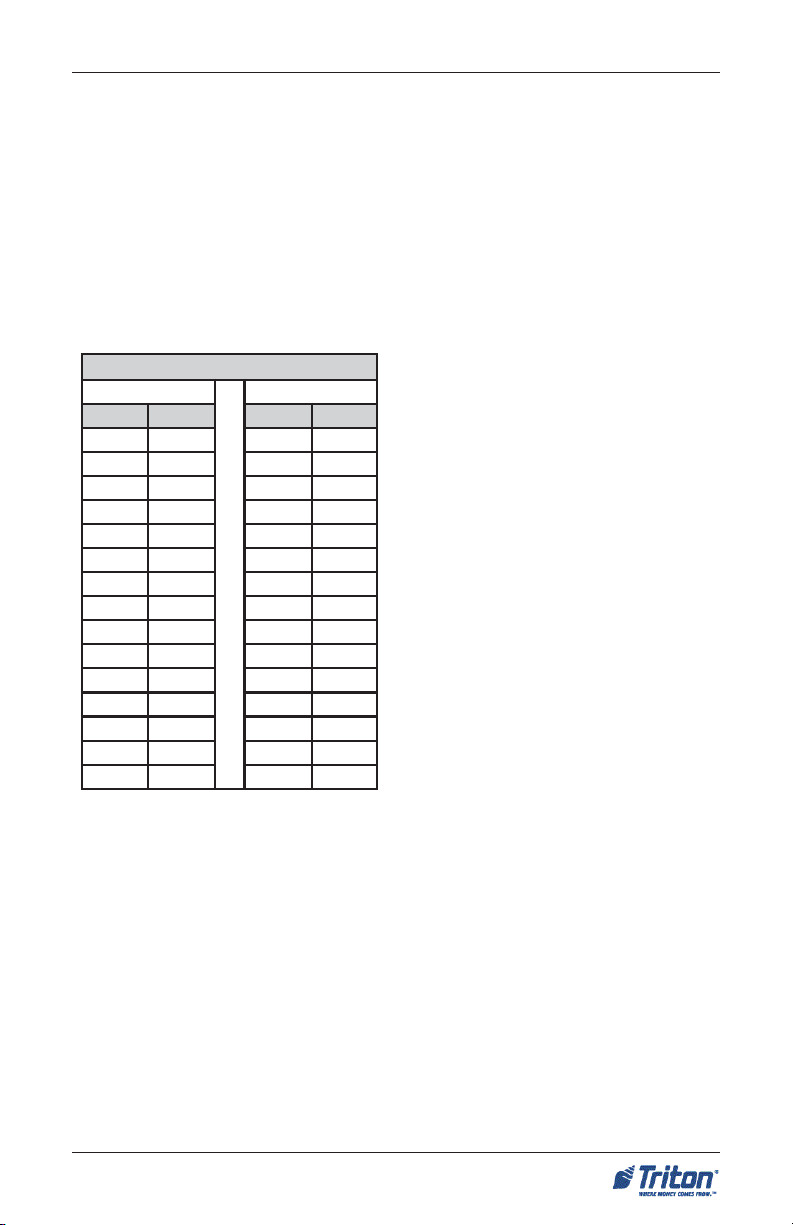
(b) Reach Depth More Than 10 inches
(255 mm). Where the reach depth to
the operable parts of any control as measured from the vertical plane perpendicular to the edge of the unobstructed
clear floor space at the farthest protrusion of the automated teller machine or
surround is more than 10 inches (255
mm), the maximum height above the finished floor or grade shall be as follows:
SNOITACIF ICEPSYTILIBISSECCA
H T P E DH C A E RTH G I E HM UM I X AM
sehcnI sretemilliM sehcnI sretemilliM
01552450731
110822/ 13 50631
21503355431
310332/ 12 55331
415532/ 11 50131
51083155921
615042/ 10 55821
71034050721
815542/ 19 45521
91584945421
020152/ 18 40321
125352/ 17 45021
22065745911
325852/ 16 40811
42016640711
(3) Forward and Parallel Approach. If
both a forward and parallel approach
are possible, operable parts of controls
shall be placed within at least one of the
reach ranges in paragraphs (1) or (2) of
this section.
EXCEPTION: Where a function can be
performed in a substantially equivalent
manner by using an alternate control,
only one of the controls needed to perform that function is required to comply
with this section. If the controls are identified by tactile markings, such markings
shall be provided on both controls.
4.34.4 Controls. Controls for user
activation shall comply with 4.27.4
(Operation).
4.34.5 Equipment for Persons with
Vision Impairments. Instructions and
all information for use shall be made accessible to and independently usable
by persons with vision impairments.
(20) Where automated teller machines (ATMs) are provided, each ATM
shall comply with the requirements of
4.34 (Automated Teller Machines) ex-
cept where two or more are provided at
a location, then only one must comply.
EXCEPTION: Drive-up-only automated
teller machines are not required to comply with 4.27 (Controls and Operating
Mechanisms) and 4.34.3 ( Reach
Ranges).
(4) Bins. Where bins are provided for
envelopes, waste paper , or other pur poses, at least one of each type provided shall comply with the applicable
reach ranges in paragraph (1), (2), or (3)
of this section.
11
Page 12

FT5000XP - SITE PREPARATION AND INSTALLATION GUIDE
4.2.4 Clear Floor or Ground
Space for Wheelchairs.
4.2.4.1 Size and Approach. The mini-
mum clear floor or ground space required to accommodate a single, stationary wheelchair and occupant is 30
inches by 48 inches (760 mm by 1220
mm) (see Fig. 4a). The minimum clear
floor or ground space for wheelchairs
may be positioned for forward or parallel approach to an object (see Fig. 4b
and 4c). Clear floor or ground space for
wheelchairs may be part of the knee
space required under some objects.
4.2.4.2 Relationship of Maneuvering
Clearance to Wheelchair Spaces. One
full unobstructed side of the clear floor
or ground space for a wheelchair shall
adjoin or overlap an accessible route or
adjoin another wheelchair clear floor
space. If a clear floor space is located in
an alcove or otherwise confined on all
or part of three sides, additional maneuvering clearances shall be provided as
shown in Fig. 4(d) and 4(e).
Figure 4a. Clear floor space.
Figure 4b. Forward approach.
4.2.4.3 Surfaces for Wheelchair
Spaces. Clear floor or ground spaces
for wheelchairs shall comply with 4.5
(Ground and Floor Surfaces).
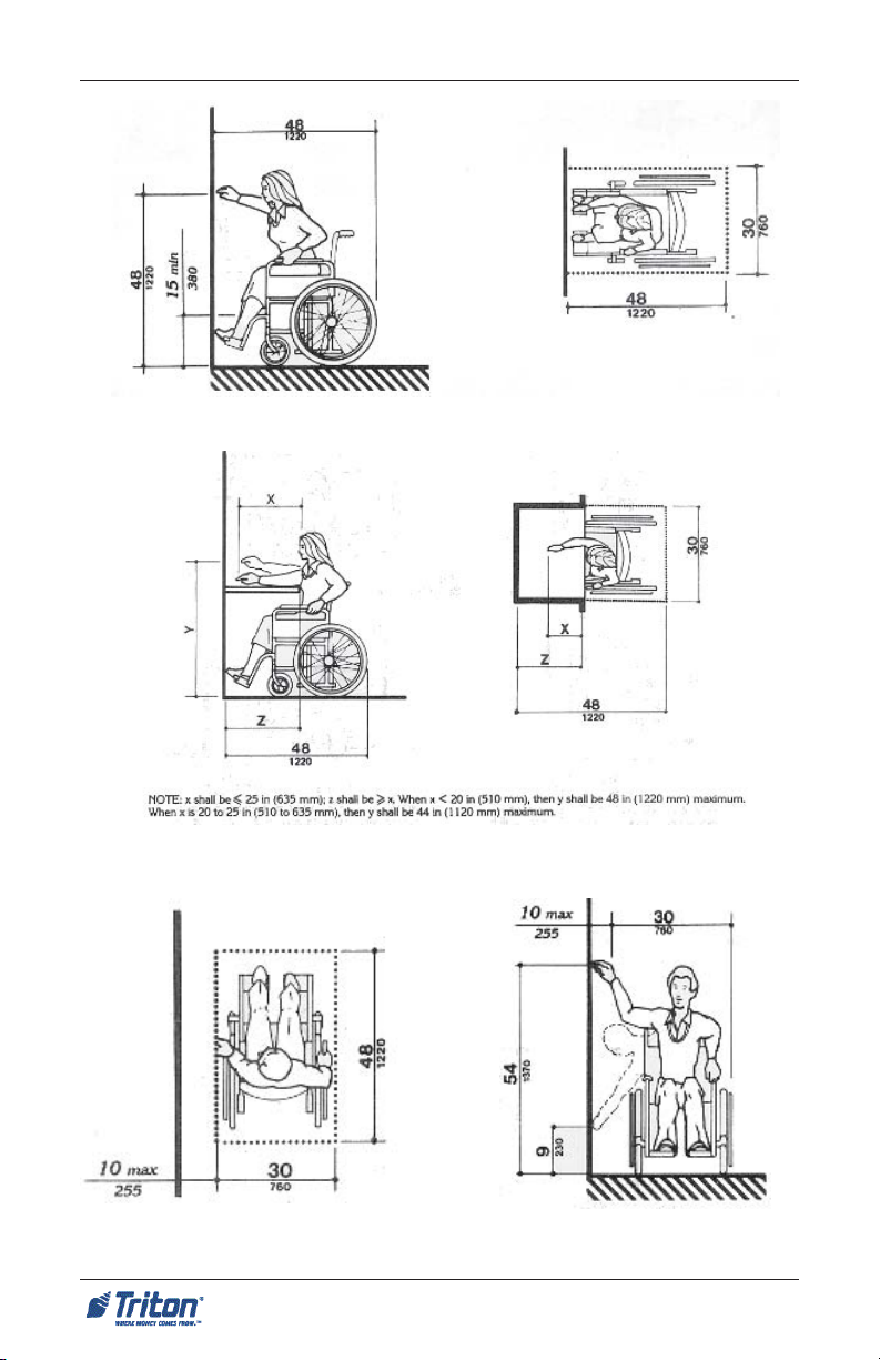
4.2.5 Forward Reach. If the clear
floor space only allows forward approach to an object, the maximum high
forward reach allowed shall be 48 inches
(1220 mm) (see Fig. 5(a)). The minimum
low forward reach is 15 inches (380 mm).
If the high forward reach is over an obstruction, reach and clearances shall be
as shown in Fig. 5(b).
Figure 4c. Parallel approach.
12
Page 13

ATM INSTALLATION FOR ACCESSIBILITY
4.2.6 Side Reach. If the clear floor space allows parallel approach by a person in
a wheelchair, the maximum high side reach allowed shall be 54 inches (1370 mm) and
the low side reach shall be no less than 9 inches (230 mm) above the floor (Fig. 6(a)
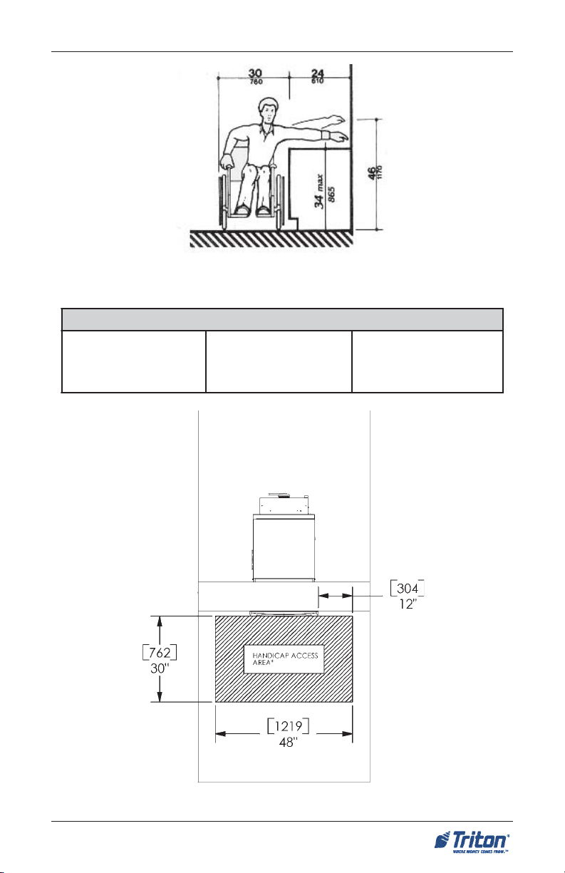
and 6(b)). If the side reach is over an obstruction, the reach and clearances shall be
as shown in Fig 6(c).
Figures 4d . Clear Floor Space in
Alcoves.
For a front approach, where the depth
of the alcove is equal to or less than 24
inches (610 mm), the required clear floor
space is 30 inches by 48 inches (760 mm
by 1220 mm).
Figures 4e. Clear Floor Space in
Alcove.
For a front approach, if the depth of the
alcove is greater than 24 inches (610 mm),
then in addition to the 30-inch (760 mm)
width, a maneuvering clearance of 6
inches (150 mm) in width is required.
For a side approach, where the depth of
the alcove is equal to or less than 15
inches (380 mm), the required clear floor
space is 30 inches by 48 inches (760 mm
by 1220 mm).
For a side approach, where the depth of
the alcove is greater than 15 inches (380
mm), then in addition to the 48-inch (1220
mm) length, an additional maneuvering
clearance of 12 inches (350 mm) is
required.
13
Page 14
FT5000XP - SITE PREPARATION AND INSTALLATION GUIDE
Figure 5a. Forward reach, unobstructed.
Figure 5b. Forward reach, obstructed.
Figure 6a. Parallel approach - side
reach.
Figure 6b. Parallel approach - high/
low side reach.
14
Page 15
ATM INSTALLATION FOR ACCESSIBILITY
Figure 6c. Side reach, ob structed.
"84
)mm9121 (
- s s o r c A-
"03
)mm267 (
-p e eD-
Floor Interior
*
ae rAsseccApac i dnaHed i s t uO
de r usa eM
fore tnecmor f
l e n a P l o r t n oC
*a i c s aF
Ground exterior
Figure 7. ADA access dimensions for FT5000XP ATM.
15
Page 16

FT5000XP - SITE PREPARATION AND INSTALLATION GUIDE
THIS PAGE INTENTIONALLY LEFT BLANK
16
Page 17

ENVIRONMENTAL PRECAUTION CHECKLIST
17
Page 18

ATM ENVIRONMENTAL PRECAUTIONS CHECKLIST
When installing an ATM, some general environmental and power precautions need to be considered. Evaluate the location where the ATM will be
installed. To help ensure proper operation of the ATM, ensure the environmental criteria listed in this checklist are met.
TEMPERATURE/HUMIDITY
1. The ATM will operate over a range
of temperatures and humidity.
Generally, these parameters must
fall within the following ranges:
Temperature (Interior)
• 10°C - 40°C
• 50°F - 104° F
Relative Humidity
• 20% - 80%
• (Non-Condensing)
Temperature (Exterior)
• -35°C - 50°C
• -30°F - 122°F
Relative Humidity
• 20% - 100%
AC POWER REQUIREMENTS
2. Ensure the following AC power
requirements are met:
Current (Max)
• 5.05A @ 120V
• 2.01A @ 240V
Voltage
• 90V - 136V @ 50/60 Hz
• 198V - 257V @ 50/60 Hz
Power Consumption (Idle)
• 2.0A @ 115 VAC at 60 Hz
• 1.0A @ 230 VAC at 50 Hz
Dedicated source. The ATMs AC
power feed will be a dedicated line to
which no other electrical devices are
connected. The ATM power line will
be wired for a single “duplex”-style
outlet and connected directly to the
AC service panel.
Isolated G round. An equipment
grounding conductor that is insulated
from the conduit or raceway and all
other grounding points throughout its
entire length. The only points of electrical connection will be at the duplex
outlet and service panel ends of the
line.
* IMPORTANT *
AC power for the terminal should
come from a dedicated source with
an isolated ground.
RF INTERFERENCE
3. Ensure there are no devices near
the terminal that may cause RF interference, such as:
TVs
Coolers
Security Devices
Neon Signs
Devices with Compressors
Power Consumption (Max Load)
• 606 Watts @ 120V
• 482 Watts @ 240V
18
Page 19
SITE PREPARATION / INSTALLATION
19
Page 20
FT5000XP - SITE PREPARATION AND INSTALLATION GUIDE
INTRODUCTION
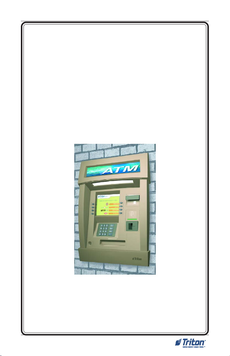
The Triton FT5000XP is a self-serviced, weatherized terminal adaptable for any suitable exterior wall or vestibule location. The cabinet design allows flexibility for
“Island” installations (wall thickness up to 6-1/4") or existing structures (wall thickness up to 10"). Built-in leveling feet and optional platforms (“plinths”) allow the
unit to be raised to the desired height of the wall opening. The following section
provides the physical dimensions and requirements for installing the FT5000XP for
your particular site location. To assist you in preparing your site, a check list is
provided of various procedures that should be carried out prior to the arrival of the
ATM. The Business Hours Cabinet is no longer offered.
T S I LKCEHCNO I T ARAP ERPE T I S
na l pr oo l fang i s eddnae t i st c e l eS
t emsno i t i dnoc l a t n emno r i vn ee r usnE
se l udehc sr odne vdnar o t c a r t nochs i l b a t sE
s t n eme r i uqe ren i lno i t a c i nummock c ehC
sdeeny rosseccano i t a l l a t sn ina l P
sno i t a r e t l a
s t neme r i uqe r l ac i r t ce l el l a t sn I
y rassecenekamdnana l proo l fkcehC
sdeenno i t a c i nummocr o fe t i se r ape rP
) l a no i t po (gn i n i a r t r o t a r e pon a l P
t s e tdnas en i lno i t a c i nummoc l l a t sn I
e l ba l i avae r ase i r osseccano i t a l l a t sn ierusnE
INSTALLATION ACCESSORIES
When installing the FT5000XP, it is recommended that you or your agent have the
following items available:
» Lifting/moving device
» Wooden/metal safety blocks
to support the ATM during
install
» Framing square
» Hammer
» Water-resistant sealant
(caulk,etc)
» Level
» Tape measure
» Crowbar(s)
» Circular/Jig saws
» Tool kit consisting of open/ closed box wrenches, magnetic Phillips/flat
screwdrivers, socket set, crescent wrench, pliers, Allen wrench set, etc.
20
Page 21
SITE PREPARATION/INSTALLATION
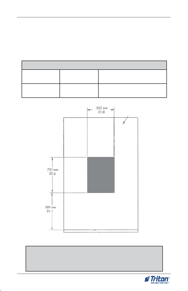
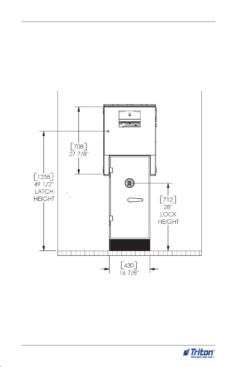
EXTERIOR WALL DIMENSIONS
The following illustrations show the nominal wall area dimensions required for
installation. Wall opening dimensions have a plus/minus (+/-) 1/4" tolerance. The
height of the opening is from exterior sidewalk level to the base of the opening to
comply with Federal ADA requirements.
gn i nepOl l aWf osno i snemi D
t hg i eHht d iW
" 8 / 5-92
)mm157 (
roi retxemor f (thgieH
) dnuo r g
" 4 / 3-12
)mm255 (
" 8 / 1-13
)mm987 (
Wall
Floor - exterior
Note
Dimensions listed comply with US Federal ADA Guidelines. For USA
installations, check for additional guidance. For non-USA installations,
check regulations relating to the country of install.
21
Page 22

FT5000XP - SITE PREPARATION AND INSTALLATION GUIDE
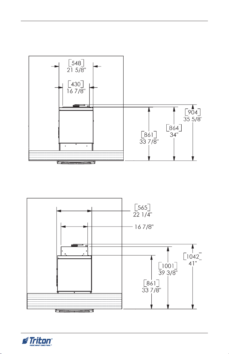
HEIGHTS TO MAIN CONTROL PANEL
The following illustrations show the heights and the Federal ADA requirements
to the main control panel items located on the FT5000
XP.
All the height dimen-
sions are calculated from the base of the exterior ground level to each item.
sme t I l en aPl o r t noCn i aMo ts t hg i eH
f o . t Hp o T
no i t cnuF
dapyeK
"84
)mm0221 (
fore tneC
d r aC
r e d a eR
" 8 / 3-1 4
)mm1501 (
fore tneC
yalpsiD
" 8 / 5-7 4
)mm0121 (
fore tneC
yarTlliB
" 4 / 1-6 3
)mm129 (
fore tneC
enohpd a eH
kcaJ
" 61 / 5-63
)mm229 (
Wall
Floor - exterior
22
Page 23

SITE PREPARATION/INSTALLATION
DETERMINE IF UNIT NEEDS A PLINTH
Triton Systems offers two (2) metal-constructed optional “plinths” w/leveling
feet. A plinth is a platform on which the ATM rests or is secured and enables the
ATM to be installed at the required height through the wall. The plinths come in
2 heights: 2-3/8” (61mm) and 4-3/4” (122 mm). You can raise the unit by a fixed
amount (2-3/8"or 4-3/4") and still be able to adjust up using the plinths leveling
feet. To determine if you need to order a plinth with your unit, a few measurements will be needed at the site.
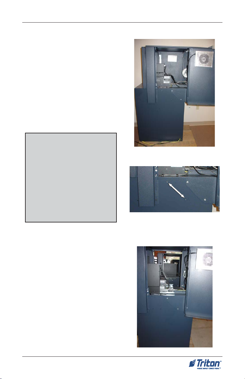
For sites that currently have a wall opening:
1. Measure from the bottom of opening to inside floor (Figure 1).
2. Cabinet dimensions are 26-1/2" from bottom of sleeve to base of cabinet
(Figure 2).
3. Subtract the difference to determine if a plinth is needed or what size plinth
to order or build. If difference is less than 2-3/8" (for example), you may
construct your own to fit. (Caution: The leveling feet on the cabinet itself
should not be used to raise the unit more than 3/4").
Figure 1. Determine height of
opening to inside floor .
Cabinet
“footprint”
26- 1/2"
Figure 2. Height of cabinet base to
bottom of sleeve (26-1/2").
23
Page 24

FT5000
XP
- SITE PREPARATION AND INSTALLATION GUIDE
ISLAND CONFIGURATION SERVICE AREA
6 -1/4" max
* Dimensions shown in inches and millimeters. Maximum wall thickness - 6-1/4" inches (160 mm)
6 -1/4" max
6 -1/4" max
24
Page 25

SITE PREPARATION/INSTALLATION
EXTENDED CONFIGURATION SERVICE AREA
10" max
10" max
* Dimensions shown in inches and millimeters. Maximum wall thickness - 10 inches (254 mm)
10" max
25
Page 26

FT5000XP - SITE PREPARATION AND INSTALLATION GUIDE
SECURING UNIT
It’s recommended that the unit be secured to the facility floor and plinth structure.
If a plinth was used, we recommend anchoring that structure first due to accessibility may be limited once the unit is mounted on the plinth. The footprint of the
cabinet floor allows for securing to either a concrete pad or plinth structure. Anchor bolts may be too short to go straight from the cabinet to the floor, depending
how high the unit was raised to accommodate the wall opening. It is the customer
or their agent’s responsibility to determine how the unit is af fixed to the facility.
Listed are some general considerations when securing the unit:
1. What is the floor structure?
(concrete, wood, etc) Do you have
anchors, lag bolts, screws to secure
cabinet/plinth?
2. Is the unit a UL Level 1 Safe cabinet
or Business Hours? Will the floor
support the weight of the cabinet?
What is the plinth constructed of?
(If you build -concrete, metal, wood,
etc).
3. Is the inside floor level the same as
the outside ground? If inside floor
is higher or lower than outside, will
you need the optional 2-3/8” or 43/4” plinths?
4. Is the floor level? Will the unit need
to be raised using the plinth/cabinet
leveling feet? (Leveling feet are for
minimal corrections to level cabinet)
5. Is exterior wall solid? (brick,
concrete) W ood framed?
Aluminum siding? Do you need to
insulate the wall cavity?
6. After cabinet is anchored, is the
control panel trim flush against the
exterior wall? Is the trim sufficiently
sealed to prevent moisture from
entering the control panel
electronics?
LEVEL 1 CABINET SAFETY
Level 1 cabinets are considerably heavier than Business Hours
cabinets! Exercise extreme cau-
tion when moving Level 1 cabinets! At least two persons should
work together to move the cabinet into position for mounting!
LEVEL FLOORING
REQUIREMENT
It is very important that the ATM
cabinet be located on flat, level
flooring! If the floor is not flat
and level, the cabinet bottom and/
or walls may become distorted
when the mounting bolts are tightened down! This could prevent
the security vault door from closing!
TOOL U SE/SAFETY
Observe ALL safety precautions
for operating hand and power
tools! Wear eye and ear protection while operating the electric
drill!
USE A BACK-SUPPORT BELT
WHEN LIFTING AND MOVING
THE ATM!
26
Page 27

SITE PREPARATION/INSTALLATION
INSTALLING CABINET THROUGH WALL OPENING
1. Carefully inspect the unit for any
shipping damage and report any
damage immediately to the
shipping company. Refer to the
warranty information in the user or
service manual (as applicable) for
information about reporting
shipping damage.
2. After unpacking the unit, remove
the dispensing mechanism
following the procedures in the
section “NMD-100 Dispensing
Mechanism:Removal/
Installation” found on pages 44-
47. After removal of the dispenser,
move the cabinet using the proper
lifting/moving device towards the
wall opening.
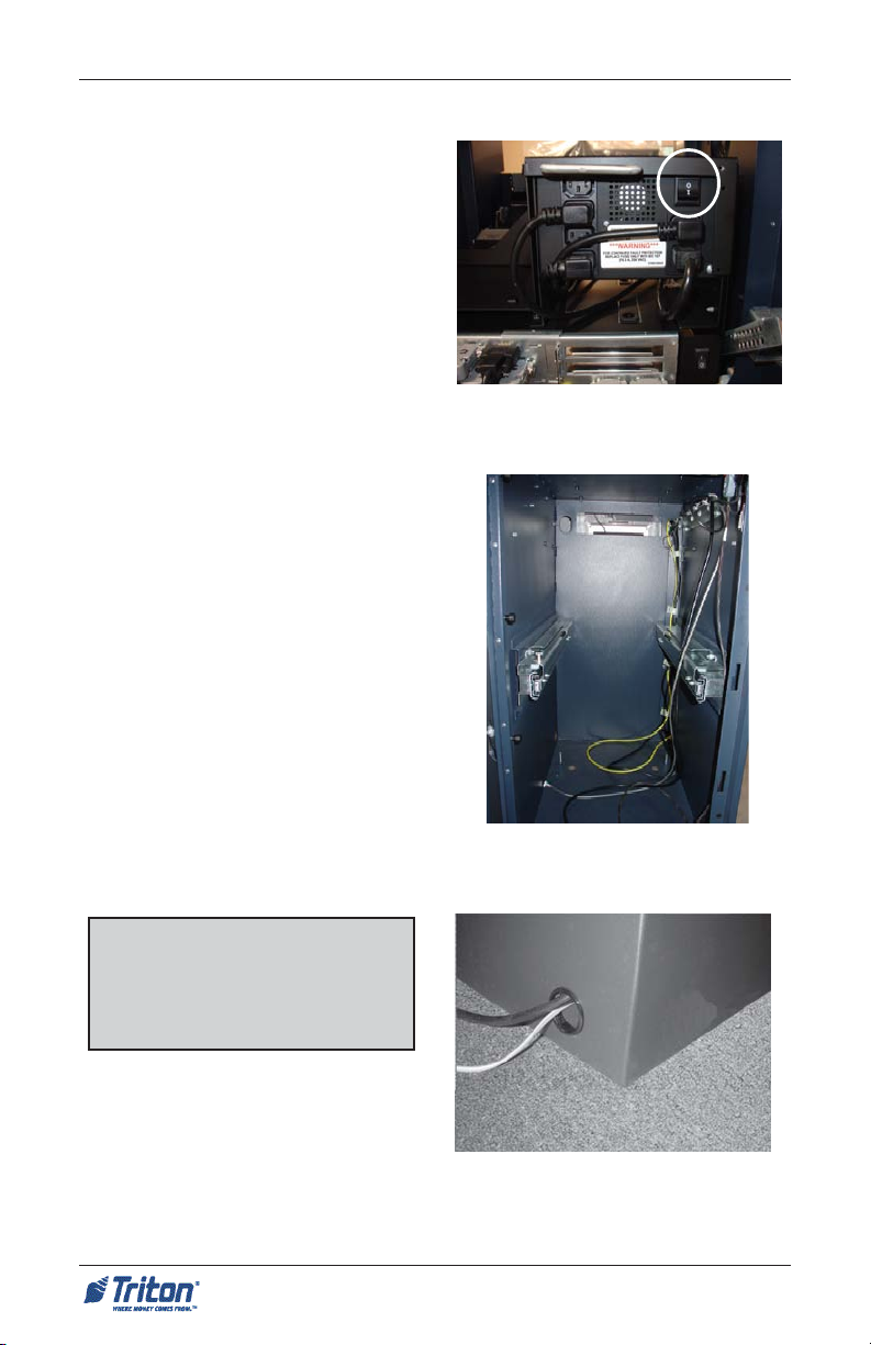
* Important*
Open the control panel sleeve door .
Verify that the power switch located
on the unit power supply is in the OFF
(0) position. See Figure 1.
3. Slide the unit up to the opening
until the sleeve portion of the
cabinet is near the wall (Figure 2).
Note
DO NOT install the control
panel trim at this time.
Figure 1. Ensure power supply is in
the OFF (0) position.
Figure 2. Slide unit up to interior
wall.
4. Measure the distance from the
bottom of the wall opening to the
bottom of the sleeve. This will be
the height requirement of the
“plinth”, if needed. Add an
additional 1/8” (3.175mm) to your
measurement for clearance (Figure
3).
Figure 3. Measure from bottom of
wall opening to bottom of sleeve.
* See Note next page for additional
measurement.
27
Page 28
FT5000XP - SITE PREPARATION AND INSTALLATION GUIDE
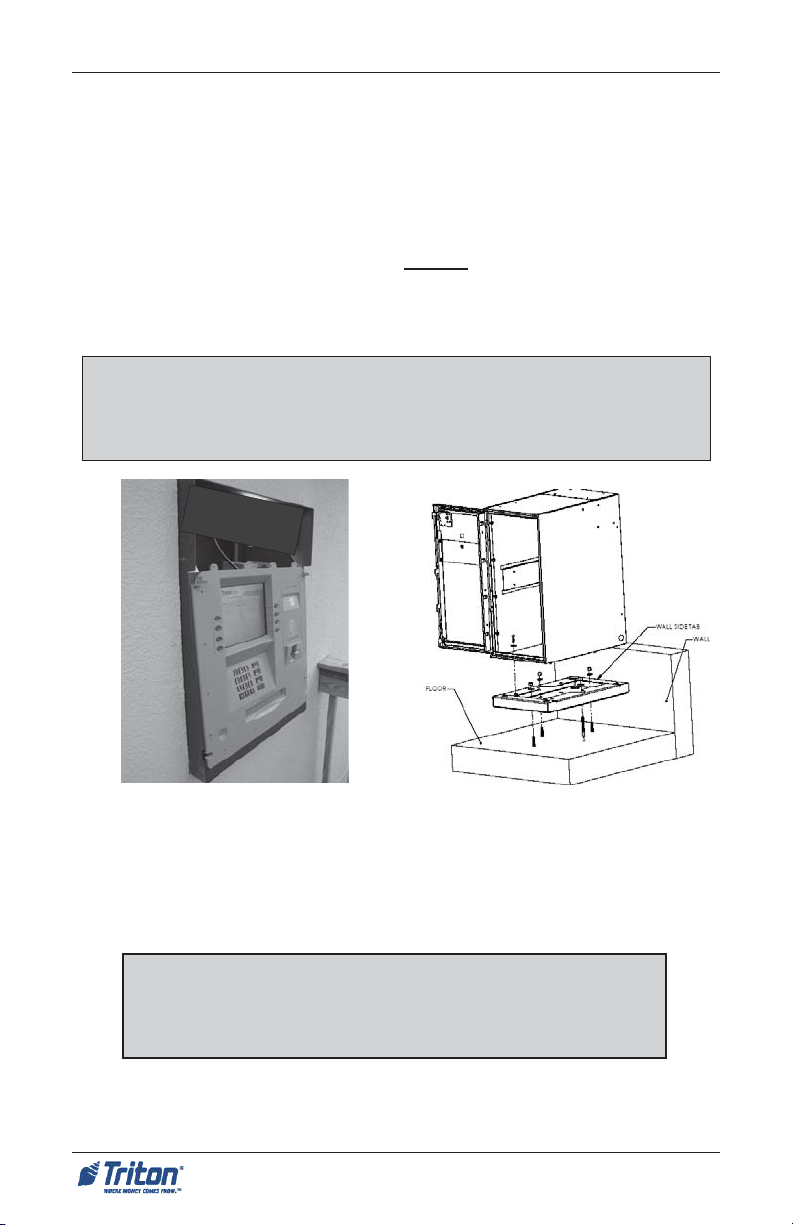
5. If no plinth is needed, slide the unit forward towards the wall opening so the
sleeve protrudes slightly out the front exterior (Figure 4). This is needed to
temporarily affix the control panel trim. Minor adjustments for raising the
unit can be made using the cabinet leveling feet (See “Adjusting Height of
Unit” page 30).
6. If a plinth is used (either built or purchased), mount the cabinet on the plinth
Figure 5). The optional plinths have a wall tab that is aligned facing the outside
exterior wall. Anchor the cabinet to the plinth using the bolts provided (optional
plinth) or secure to your built plinth. Tighten bolts enough to secure the two
together for moving the unit.
Note
Before installing the plinth, adjust the leveling feet a 1/4" (6mm) below the
platform to gain access with an open-end box wrench for additional
adjustments.
Sleeve
Figure 4. Sleeve pr otrudes slightly.
7. Slide/move the unit forward towards the wall opening so the sleeve protrudes
slightly out the front exterior (Figure 4). This is needed to temporarily affix
the control panel trim. Minor adjustments for raising the unit can be made
using the plinths leveling feet (See “Adjusting Height of Unit” page 30).
**Caution**
When placing the unit on the plinth, be careful not to damage the
front of the sleeve as this has the control panel electronics and
hardware mounted.
8. Locate the control panel trim included with the unit accessories. On the back
side are 4 clips (Figure 6a) that will align with 4 slots on the control panel (Figure
6b).
Figure 5. Mount cabinet on plinth.
28
Page 29

SITE PREPARATION/INSTALLATION
Figure 6a. Location of clips on control panel trim.
9. Temporarily mount the trim on the
protruding sleeve. DO NOT secure
with screws at this time.
10. Slide the unit back until the control
panel trim is flush to the exterior
wall (Figure 7).
11. Adjust the plinth’s leveling feet to
ensure the control panel trim is flush
against the exterior wall and the
cabinet is level.
12. Mark the anchor holes through the
cabinet floor or mark around the
plinth structure using masking
tape, pencil, etc. Remove the
control panel trim and slide the unit
back inside.
13. Remove the unit from the plinth (if used). Align the plinth over the markings and
mark the anchor holes. Drill the anchor holes and secure the plinth (if used) to
the floor. Mount the unit back on the plinth (if used) and again slide the unit
forward towards the wall opening until the sleeve protrudes slightly out the
front exterior.
If no plinth was used, after drilling the anchor holes, again slide the unit forward
towards the wall opening until the sleeve protrudes slightly out the front exterior.
Figure 6b. Location of slots on sleeve
control panel.
Figure 7. Slide unit back flush to wall.
Page 31 continues with the installation of the control panel trim.
29
Page 30

FT5000XP - SITE PREPARATION AND INSTALLATION GUIDE
Adjusting Height of Unit
Triton Systems offers two (2) metal-constructed optional plinths w/leveling
feet. The plinths come in 2 heights: 2 - 3/8" (61 mm) and 4 - 3/4" (122 mm).
Based on the height requirement needed, you can either:
1) Raise the unit with the leveling feet installed in the cabinet (Business
Hours and Level 1) using a 1/4" (6mm) nut driver/socket.
Caution: The leveling feet are primarily for that purpose - leveling the ATM,
not to raise the unit by more than 3/4".
2) Construct your own. A “plinth” is a platform on which the ATM rests or
is secured. A plinth enables the ATM to be installed at the required height
through the wall. If built, it must be no smaller than the base of the cabinet
and must be constructed of a material that is capable of supporting the
weight of the ATM.
3) Purchase an optional plinth (Figure below). Raise the unit by a fixed
amount (2 - 3/8" or 4 - 3/4") and, if needed, adjust up using the plinths
leveling feet (see Note below).
Caution: Leveling feet are primarily used for that purpose - leveling the
ATM, not to raise the unit by more than 3/4".
4) “Stack” the optional plinths. Before securing two (2) plinths together ,
remove the leveling feet from the top plinth.
cc
c Anchor hole
cc
dd
d Leveling foot
dd
ee
e Cabinet hole
ee
Note
Before installing the plinth, adjust the leveling
feet a 1/4" (6mm) below the platform to gain
access with an open-end box wrench for
additional adjustments.
30
Page 31

SITE PREPARATION/INSTALLATION
INSTALLING CONTROL PANEL TRIM
1. Locate the control panel trim
included with the unit accessories.
On the back side are 4 clips (Figure
1a) that will align with 4 slots on
the sleeve control panel (Figure 1b).
2. Before mounting the trim, ensure
the speaker wires and LED light
cables are routed through the
opening above the control panel.
These will be connected later. Align
the trim clips with the sleeve slots
and insert until the trim is seated
on the control panel.
3. Once the trim is in place, open the
side panels on the cabinet sleeve
and secure the trim panel with 16
Phillips head screws included in the
accessory kit (4 on each side).
Figure 1a. Location of clips on control panel trim.
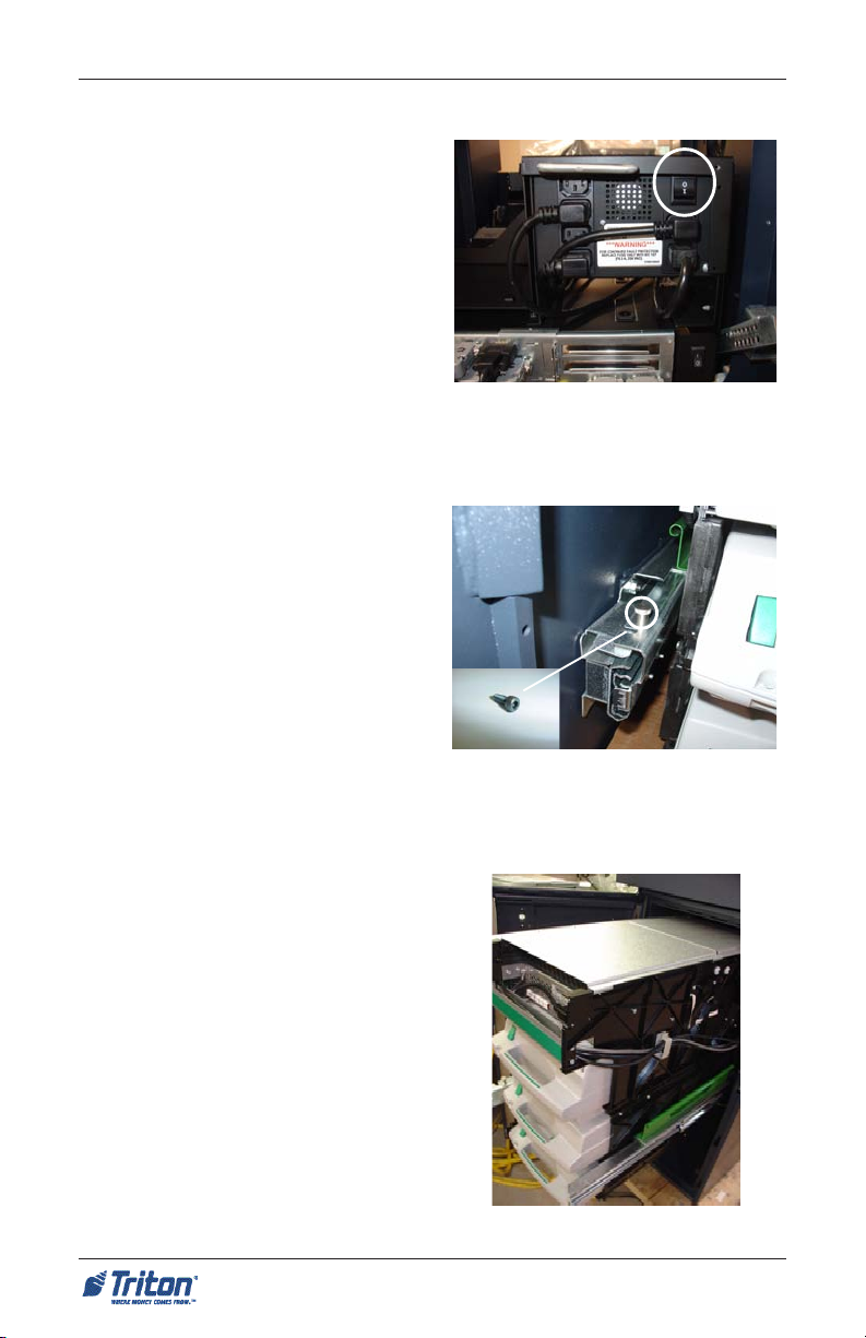
Note
2 screws holes are accessed inside
the small silver panel (Figure 2a).
Slide the dispensing mechanism
back approximately one (1) foot and
use a magnetic Phillips driver to hold
screws. Screw holes are located in
upper slots shown in Figure 2b.
Figure 2a. Remove retaining screw
to open panel.
Figure 1b. Location of slots on control panel.
Figure 2b. Screw locations for securing bottom of trim .
31
Page 32
FT5000
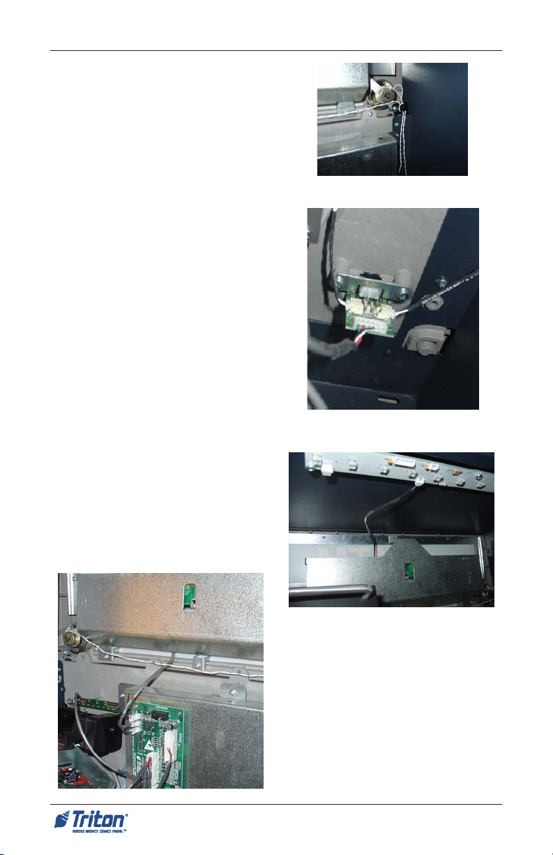
4. After the control panel trim has
been secured, route the speaker
wires through the cable clip shown
in Figure 3. Connect the speaker
wires to the audio input circuit
board located in the lower right
corner of the cabinet (Figure 4).
5. Connect the trims upper LED light
cable to the cabinets LED light
assembly shown in Figure 5.
Connect the lower cable to the
docking board assembly (J3)
shown in Figure 6.
6. With 2 persons (inside/outside),
slide the whole unit back inside
until the control panel trim is flush
with the outside wall.
7. Before securing/anchoring the
cabinet, check to ensure the control
panel trim is flush against the
exterior wall. Minor adjustments
can be made using the cabinet
leveling feet.
XP
- SITE PREPARATION AND INSTALLATION GUIDE
Figure 3. Route speaker wires.
Speaker wires
Figure 4. Connect speaker wires to
audio board.
8. Secure/anchor the cabinet to the
floor or plinth, if used. Cabinet/trim
installation is complete.
Figure 5. Upper trim cable con-
nected to LED light assembly.
Figure 6 (Left). Lower cable
connected to docking board (J3).
32
Page 33
SITE PREPARATION/INSTALLATION
EXTENDED CONFIGURATION
The illustration on right shows the
FT5000XP extended. The primary purpose for this configuration is for installation in facilities with exterior walls having a maximum thickness of 10 inches
(254 mm). The dispensing mechanism
has a bill chute extension designed for
the elongated configuration. A protective plate is inserted on the underside
of the cabinet sleeve for security and
environmental purpose.
**Warning**
Units are shipped as specified configurations and the dispensing mechanism assembled with the required bill
chute extension. Changing configurations require dispenser modifications and/or additional hardware.
YOU CAN NOT CHANGE
CABINETCONFIGURATIONS
WITHOUT THE REQUIRED
HARDWARE.
Figure 1 2. Extended co nfiguration.
Figure 13. Screw holes for
Island configuration.
ISLAND CONFIGURATION
The illustration on right shows the
FT5000XP “collapsed” or Island configuration. The cabinet sleeve is moved
back approximately 5 - 7/16" inches (137
mm). This configuration allows installation in facilities with exterior walls having a maximum thickness of 6 - 1/4"
inches (160 mm). The dispensing mechanism has a shortened bill chute extension due to the collapsed state of the
unit.
Figure 14. Island con figuration.
33
Page 34
FT5000XP - SITE PREPARATION AND INSTALLATION GUIDE
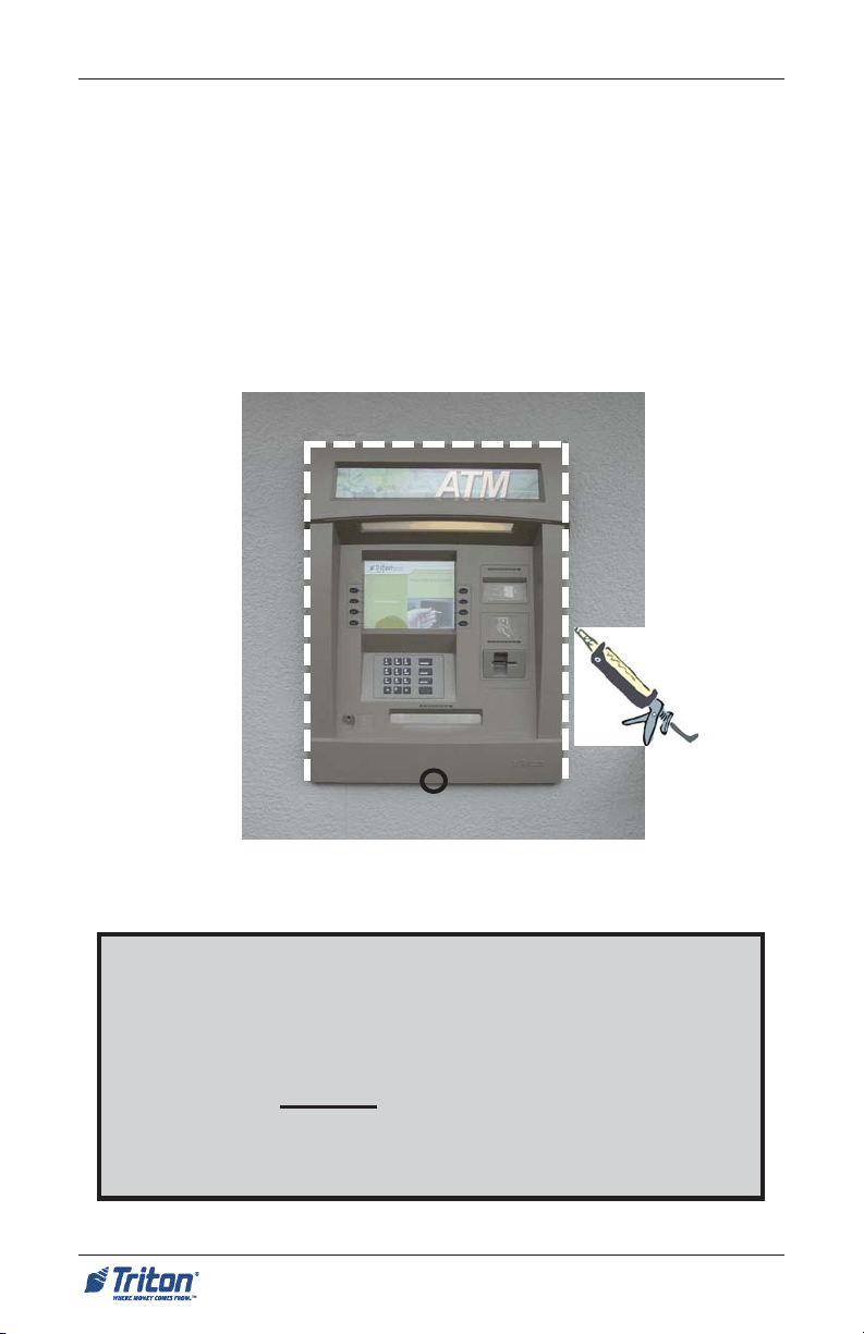
SEALING THE CONTROL PANEL TRIM
To ensure that the temperature around the unit is maintained during cold weather,
it’s important that the wall opening is prepared correctly . Any cavity in the wall
should be sealed to provide a flush surface. The gap between the ATM and the
inside wall opening should be left clear to allow air to circulate at room temperature.
After the control panel trim is installed, a good weather seal is needed between the
exterior wall and the trim. A suitable water -resistant sealant product is required
around the periphery of the control panel trim. There are also products that are color
tinted to closely match the trim color.
Drain hole location
Figure 15. Control panel trim sealed.
**IMPORTANT**
SEAL THE TRIM TO THE EXTERIOR WALL WITH A
WATER-RESISTANT SEALANT TO PREVENT WATER
INTRUSION. DO NOT SEAL AROUND THE BOTTOM
OF THE TRIM! A SMALL DRAIN HOLE IS LOCATED
ON THE UNDERSIDE THAT MUST BE CLEAR.
34
Page 35
SITE PREPARATION/INSTALLATION
CABINET DIMENSIONS
The following illustrations show dimensions of the cabinet in the Extended and
Island configurations. Note: Plinths shown are with the 4-3/4" option.
* These dimensions are only accurate if inside and outside “floor” level is the
same. If not, the dimensions should be modified accordingly.
Rear View
Floor-interior
35
Plinth
(4-3/4")
Floor-interior
Page 36
FT5000XP - SITE PREPARATION AND INSTALLATION GUIDE
CABINET DIMENSIONS
Top View (Island)
Wall (6-1/4” max)
Top View (Extended)
Wall (10” max)
36
Page 37

* 4-3/4"
SITE PREPARATION/INSTALLATION
CABINET DIMENSIONS
6-1/4"
WALL
Side View (Island)
Cable
entry
Plinth
Floor-interior Ground-
Side View (Extended)
* 4-3/4"
Floor-interior
exterior
Plinth
10"
WALL
Cable
entry
Ground-
exterior
37
Page 38

FT5000
XP
- SITE PREPARATION AND INSTALLATION GUIDE
THIS PAGE INTENTIONALLY LEFT BLANK
38
Page 39

POWER AND COMMUNICATION
39
Page 40
FT5000XP - SITE PREPARATION AND INSTALLATION GUIDE
CONNECTING AC POWER AND ETHERNET CABLE
1. Unlock and open the control
panel sleeve door. Rotate the Rear
Service Display and Keyboard
Assembly out by pulling down
the locking pin. Verify that the
power switch located on the
power supply (Figure 1) is in the
OFF (0) position. Close the
control panel door.
2. Open the security vault door .
Ensure the power and Ethernet
cables are routed through the
cable clips located in the vault
cabinet (Figure 2).
3. Route the AC power cord and the
Ethernet (CAT-5) cable through
either of the cable access holes
(as applicable) in the security
cabinet, as shown in Figure 3.
4. Install the supplied snap bushing
into the access hole that carries
the power and phone cords. See
Figure 3.
5. Plug the AC power plug into the
wall outlet.
* IMPORTANT *
AC power for the terminal should
come from a dedicated source with
an isolated ground.
Figure 1. Ensure power supply is in
the OFF (0) position.
Figure 2. Power and Ethernet cables
secured to cabinet.
6. Plug the Ethernet (CAT-5) cable
into the wall mounted jack.
Figure 3. Route cables through access
holes. I nstall snap bushing.
40
Page 41

POWER AND COMMUNICATION
*** WARNING***
This unit may be equipped with more than one power
cord. DISCONNECT ALL POWER CORDS PRIOR
TO SERVICING!
POWER OUTLET
ACCESSIBILITY
Whether you are installing a new
outlet, or plan to use an existing
outlet to supply power to the ATM,
make sure the following requirements are met:
1. The outlet is located near the
cabinet.
2. The outlet is easily accessible.
3. Access to the outlet will not be
blocked once the cabinet is installed!
POWER SUPPLY CORD
SPECIFICATIONS
For European applications, the power
supply cord must conform to the following specifications:
1. Two-conductor with physical
earth ground.
2. IEC 320 molded connector on
one end and molded plug on the
other end.
3. Certified for country of
installation.
4. Rated minimum H05VV-F with
minimum 0.75 mm2 (except where
specific countries require 1.0
mm2) conductors.
5. Maximum length: 3 meters.
41
Page 42

FT5000XP - SITE PREPARATION AND INSTALLATION GUIDE
THIS PAGE INTENTIONALLY BLANK
42
Page 43

NMD-100 DISPENSING MECHANISM
REMOVAL / INSTALLATION
43
Page 44
FT5000XP - SITE PREPARATION AND INSTALLATION GUIDE
REMOVING/INSTALLING THE NMD-100 DISPENSING MECHANISM
The dispensing mechanism for the
FT5000XP unit is shipped mounted on
the slide rails inside the security
vault. Several protective foam packs
have been strategically placed behind
and along each side of the dispensing
mechanism to reduce any movement
during transit. The foam packs and
cardboard that secures the cassettes
must be removed before the dispensing mechanism can be extended out.
Follow the procedures below for removal.
Locking pin
Figure 1. Ensure power supply is in
the OFF (0) position.
REMOVING THE NMD-100
1. Unlock and open the control
panel sleeve door. Verify that the
power switch located on the
power supply (Figure 1) is in the
OFF (0) position. Close the
control panel door.
2. Open the security vault and remove all protective foam packs
from around the dispensing
mechanism.
3. Remove the transport 5/32" Allen
screws located on top front of
both slide rails (Figure 2). DIS-
CARD SCREWS AFTER REMOVAL!
4. Pull the dispensing mechanism
out of the cabinet until it reaches
its fully extended position (Figure 3). The left slide rail has a
locking pin that must be disengaged to extend the rail (Figure
2).
Locking pin
Allen screw
Figure 2. Remove and discard
transport screw, if applicable.
Figure 3. Dispenser fully extended.
44
Page 45
NMD-100 DISPENSING MECHANISM REMOVAL/INSTALLATION
5. Turn the dispenser power switch located just to the right of the power
connector to OFF (0) (Figure 4).
6. Refer to Figures 4 and 5. Disconnect the DC power, serial communications,
and shutter cables from the dispensing mechanism. Remove the cables
from the cable clips attached to sides of dispenser.
On/Off switch
AC power cable
Figure 4. Remove AC power cable.
7. Using two persons, grasp the
green handles and lift the dispenser off the rails and slide out
of the cabinet (Figure 6). Place the
dispenser in a safe location where
it will not get accidently damaged.
8.* If installing the cabinet at this
time, follow the procedures provided in “Site Preparation” section of this manual.
Shutter
cable
Serial cable
Figure 5. Remove shutter and serial
cables (left side of dispenser).
Figure 6. Lift dispenser off rails and
guide out of cabinet. Use 2-person lift!
***WARNING***
Two persons recommended to remove the dispenser from the cabinet. When
removing dispenser from cabinet, use caution not to damage the throat
extension on front of dispenser mechanism.
45
Page 46

FT5000XP - SITE PREPARATION AND INSTALLATION GUIDE
INSTALLING THE DISPENSING MECHA-
NISM INTO THE CABINET
**CAUTION**
Be certain that you have not applied
power to the ATM before you continue! See Pg.44 for the ATMs power
supply location and On/Off switch.
1. Refer to Figure 1. Pull the slide
rails out of the cabinet until they
reach their fully extended position. The left slide rail has a locking pin that must be disengaged
to extend the rail. Ensure all cables
have been moved out of the way
so they will not be damaged while
installing the dispensing mechanism in the cabinet.
2. Pick up the dispensing mechanism by the handles and load it
on to the slide rail by aligning the
tabs (under handle) into the rail
slots. (Figures 1 and 2)
Rail slots
Figure 1. Slide rails extended.
Tab
Rail slot
Figure 2. T ab into rail slot. Use 2person lift!
***WARNING***
Use only the green handles and
drive motor in rear of dispenser to
lift the mechanism. Two persons
recommended t o install the dispenser on to the slide rails.
3. Refer to Figure 3. Route the dispensers AC power, shutter, and serial data cables as shown in Figure
3 (right side of dispenser).
Figure 3. Route cables through cable
clip.
46
Page 47

NMD-100 DISPENSING MECHANISM REMOVAL/INSTALLATION
4. Refer to Figure 4. Connect the serial communication data cable and
the shutter cable to the connectors
on the left side of the dispenser .
For the serial data cable, use the
forward -most connector as shown.
The plug is keyed to ensure proper
installation.
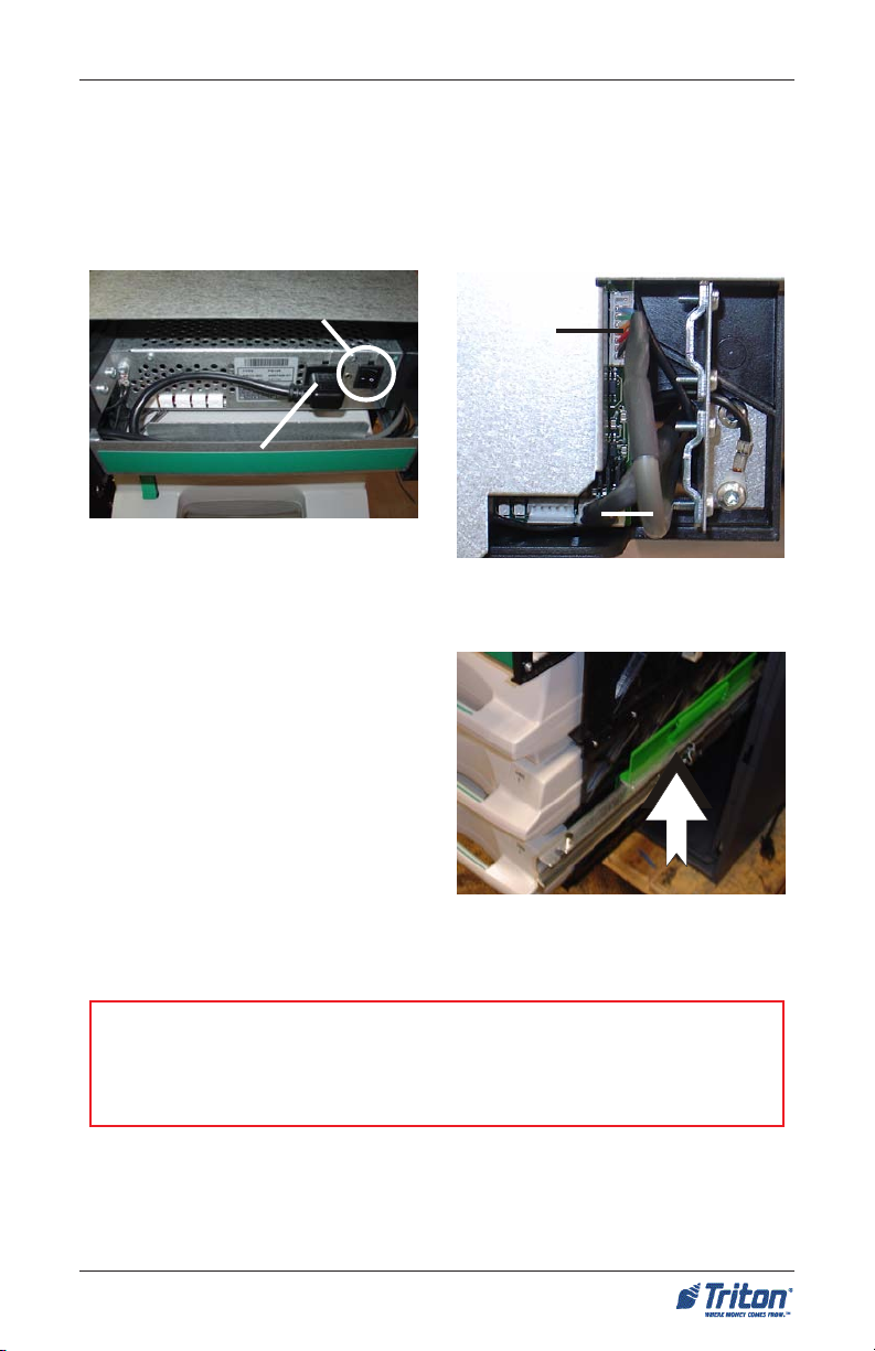
5. Connect the AC power cable to the
dispenser power supply (Figure
5).
6. Disengage the slide rails by lifting
up/down on the locking lever located in Figure 6 (both sides). Slide
the dispenser into the cabinet until
the slide rail locking pin is engaged.
(Figure 7)
7. Turn the dispenser power switch
located just to the right of the power
connector to ON (I).
Shutter cable
connector
Serial cable
connector
x
Figure 4. Shutter and data cable
connectors.
AC power cable connector
Figure 5. AC power cable connection.
Figure 7. Slide dispenser into cabinet.
Figure 6. Disengage slide rails.
47
Page 48

FT5000
XP
- SITE PREPARATION AND INSTALLATION GUIDE
THIS PAGE INTENTIONALLY LEFT BLANK
48
 Loading...