

Page 1
Operating and
Safety Instructions
Mini Sliding Extension Table
ETA100
www.tritontools.com
Page 2

2
GB
Thank you for purchasing this Triton product. These instructions contain information necessary
for safe and effective operation of this product.
Please read this manual to make sure you get the full benefit of its unique design.
Keep this manual close to hand and ensure all users of this product have read and fully understand the instructions.
CONTENTS
Symbols 2
Parts list 2
Safety 7
Assembly 6
Operating 7
Angle settings 9
Guarantee 9
SYMBOLS
Always wear ear, eye and respiratory
protection.
Conforms to relevant legislation
and safety standards.
PARTS LIST
Table Assembly
1. Long Extrusions (2)
2. Short Extrusion Assemblies (2)
3. Scales (2)
4. Brace (1)
5. Corner Brackets (4)
6. Inner Bearings (smaller) (2)
7. Outer Bearings (larger) (2)
8. Fence Assembly (1)
Fastener Bag 1
9. Brace Brackets (2)
10. Flange Nuts M6 (8)
11. Hex Bolts M6 x 10 (14)
12. Hex Nuts M6 (6)
13. Washers M6 (14)
14. Screws M6 x 16 (4)
15. Fence Bolts with square plastic feet (15)
16. Fence Sliders (2)
17. Round Knobs with Nut (2)
Contents / Symbols / Parts List
Do not use before viewing and
understanding the full operating
instructions
Outer Track Assembly
18. Outer Track (1)
19. Legs (2)
20. Feet (2)
21. Leg Plates (4)
22. Leg Clamp Assemblies (2)
Fastener Bag 2
17. Round Knobs with Nut (2)
23. Hex Bolts M6 x 40 (6)
24. Nyloc Nuts M6 (6)
25. Screws M4 x 10 (4)
26. Square Nuts M4 (4)
27. Height Stops (2)
28. Coach Bolts M6 x 20 (2)
29. Angled Tube Closers (2)
30. Flat Tube Closers (4)
Fastener Bag 4
13. Washers M6 (4)
24. Nyloc Nuts M6 (4)
31. Shims (2)
32. Coach Bolts M6 x 50 (4)
Instruction warning.
Inner Track Assembly
33. Inner Track (1)
34. Support Brackets (2)
35. Skid Assemblies (2)
36. Front Panel Bracket (1)
37. Rear Panel Bracket (1)
38. TCA/RSA Brackets (2)
39. Spacer Blocks (2)
Fastener Bag 3
10. Flange Nuts M6 (2)
13. Washers M6 (4)
17. Round Knobs with nut (2)
24. Nyloc Nuts M6 (6)
28. Coach Bolts M6 x 20 (2)
40. Coach Bolts M6 x 12 (4)
41. Locking Latches (2)
42. Hex Bolts M6 x 45 (2)
43. Screws M6 x 10 (2)
Page 3

3
GB
Fig. 1
10
17
8
16
15
3
10
1
2
9
13
11
13
9
11
7
13 5
11
12
9
14
6
12
3
1
Fig. 2
21
25
18
30
27
17
16
23
21
29
26
22
18
25
25
19
20
24
Fig. 3
Workcentre
Fig. 4
Compact Saw Table
22
Fig. 5
Router Stand
30
33
42
24
41
24
13
24
33
42
13
41
24
40
34
28
17
40
38
35
35
33
32
42
24
41
31
39
38
13
24
Parts List
35
Page 4

4
GB
Fig. 6
Fig. 8
Compact Saw Table
Fig. 7
Fig. 9
Router Stand
Parts List
Page 5

5
GB
Fig. 12
Fig. 10
Fig. 13
Fig. 11
Fig. 14
Fig. 15
Fig. 16
Parts List
Page 6
6
GB
Fig. 17
Fig. 18
Fig. 21
Fig. 19
Fig. 20
Fig. 23
Fig. 22
Parts List
Page 7

7
GB
SAFETY INSTRUCTIONS
WARNING. Read all instructions. Read all
safety warnings and all instructions. Failure
to follow the warnings and instructions my result
in electric shock, fire and/or serious injury.
Save these instructions
1. WORK AREA SAFETY
a. Keep work area clean and well lit. Cluttered and
dark areas invite accidents. b. Do not operate
power tools in explosive atmospheres, such
as in the presence of flammable liquids, gases
or dust. Power tools create sparks which may
ignite the dust or fumes. c. Keep children and
bystanders away while operating a power tool.
Distractions can cause loss of control.
2. ELECTRICAL SAFETY
a. Power tool plugs must match the outlet. Never
modify the plug in any way. Do not use any
adapter plugs with earthed (grounded) power
tools. Unmodified plugs and matching outlets will
reduce risk of electric shock.
b. Avoid body contact with earthed or grounded
surfaces such as pipes, radiators, ranges
and refrigerators. There is an increased risk
of electric shock if your body is earthed or
grounded.
c. Do not expose power tools to rain or wet
conditions. Water entering a power tool will
increase the risk of electric shock.
d. Do not abuse the cord. Never use the cord for
carrying, pulling or unplugging the power tool.
Keep the cord away from heat, oil, sharp edges
or moving parts. Damaged or entangled cords
increase the risk of electric shock.
e. When operating a power tool outdoors, use an
extension cord suitable for outdoor use, this will
reduce the risk of electric shock.
f. If operating a power tool in a damp location is
unavoidable, use a residual current device (RCD)
protected supply, which will reduce the risk of
electric shock.
3. PERSONAL SAFETY
a. Do not use power tools while you are tired
or under the influence of drugs, alcohol or
medication. A moment of inattention while
operating power tools may result in serious
personal injury.
b. Always use safety equipment: wearing eye
protection, dust mask, non-slip safety shoes,
hard hat and hearing protection used in
appropriate conditions will reduce personal
injuries.
c. Avoid accidental starting. Ensure the switch is
in the ‘Off’ position before plugging in. Carrying
power tools with your finger on the switch or
connecting to power with the switch on the ‘On’
position invites accidents.
d. Remove any adjusting key or wrench before
turning the power tool on. A wrench or a key left
attached to a rotating part of the power tool may
result in personal injury.
e. Do not over-reach. Keep proper footing and
balance at all times. This enables better control
of the power tool in unexpected situations.
f. Wear suitable clothing and footwear. Do not
wear loose clothing, neckties, jewellery, or other
items which may become caught. Wear non-slip
footwear or where appropriate, footwear with
protective toe caps. Long hair should be covered
or tied back.
g. If devices are provided for the collection of
dust particles, ensure these are connected and
properly used. Use of these devices can reduce
dust related hazards.
4. POWER TOOL USE AND CARE
a. Do not force the power tool. Using the correct
power tool for your application will be safer and
produce better results at the rate for which it
was designed.
b. Do not use the power tool if the ‘On/Off’ switch
is not working correctly. Power tools that cannot
be controlled by the switch are dangerous and
must be repaired prior to use.
c. Disconnect the plug from the power source
before making any adjustments, changing
accessories or storing power tools. Such
preventive safety measures reduce the risk of
starting the power tool accidentally.
d. Power tools are dangerous in the hands of
untrained users. Store power tools out of reach
of children, and do not allow persons who are
unfamiliar with the product or these instructions
to operate the power tool.
e. Maintain power tools. Check for misalignment,
binding or breakage of moving parts, and any
other condition that may affect the operation of
the power tool. If damaged, have the power tool
Safety Instructions
Page 8

8
GB
repaired before use. Accidents are caused by
poorly maintained power tools.
f. Keep cutting tools sharp and clean. Properly
maintained cutting tools with sharp cutting
edges are less likely to bind and are easier to
control.
g. Use the power tool, accessories and tool bits in
accordance with these instructions and in the
manner intended for the particular type of power
tool, taking into account the working conditions
and the work to be performed. Failure to use
the tool for its intended purposes could result
in a hazardous situation and may invalidate the
warranty.
5. SERVICE
a. Have your power tool serviced by a qualified
repair technician, using only identical
replacement parts. This will ensure that the
safety of the power tool is maintained.
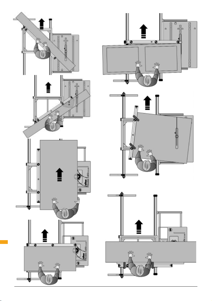
ASSEMBLY
ASSEMBLING THE TABLE & RIP FENCE
STEP 1
Using the fasteners from Fastener Bag 1, insert 4
Flange Nuts (10) into each Long Extrusion (1) as
shown in Inset 1 on (Fig. 1).
Lay out the two long extrusions and the two short
extrusions as shown, making sure that all of the
flange nuts are facing inwards.
Plug the corner blocks of the Short Extrusion
Assemblies (2) into the ends of the long extrusions
and tap fully home with a rubber mallet (or similar).
STEP 2
Turn the table over (face down) on a flat surface
and loosely attach the Corner Brackets (5), using
the Hex Bolts (11) and Washers (13) into the flange
nuts. (Slide the flange nuts into position using a
screwdriver).
Ensure that the two printed corner brackets are
bolted with their correct edges on the same long
extrusion, as illustrated on the brackets.
Loosely fit the Brace Brackets (9) to the Brace (4)
using Hex Bolts (11), Washers (13) and Hex Nuts
(12). See Inset 2 on (Fig. 1).
NOTE: The tool must be used only for its prescribed
purpose. Any use other than those mentioned in
this manual will be considered a case of misuse.
The user and not the manufacturer shall be liable
for any damage or injury resulting from such
cases of misuse. To use this tool properly observe
the safety regulations, assembly instructions
and operating instructions, which can be found
in this manual. All persons who use and service
the machine must be informed about its potential
hazards and be acquainted with this Manual.
Children and frail people must not use this tool.
Children should be supervised at all times if they
are in the area in which the tool is being used. It
is also imperative that you observe the accident
prevention regulations in force in your area. The
same applies for general rules of occupational
health and safety. The manufacturer shall not be
liable for any changes made to the tool nor for any
damage resulting from such changes. Even when
the tool is used as prescribed it is not possible to
eliminate all residual risk factors.
Position the brace centrally between the short
extrusions, as shown, and loosely attach it with hex
bolts and washers into the remaining flange nuts.
Do not tighten any of the fasteners yet.
STEP 3
Turn the table face upwards again and insert the
Scales (3) between the long extrusions and the
brace and corner brackets. Position them with the
3
14
⁄4" ends hard up against the short extrusion on
the 'map of Australia' side of the table. Push the
scales down until they 'click' into location, flush
with the top face of the long extrusions, as shown
in Inset 3 on (Fig. 1).
Turn the table over again (face down). Make sure
the corner brackets are pushed fully into the
corners, and that the plastic corner blocks are still
fully inserted into the ends of the extrusions.
Tighten the 8 bolts holding the corner brackets. Do
not over-tighten. (Tighten each pair of bolts a little
at a time, to ensure you don’t distort the frame).
Next tighten the 4 bolts holding the brace bracket
to the long extrusion, and finally tighten the bolts in
the brace.
Safety Instructions / Assembly
Page 9

9
GB
STEP 4
Plug the two smaller Inner Bearings (6) into the
corner blocks below the low scale readings and
tighten using the Countersunk Screws (14) and
Hex Nuts (12). The two longer Outer Bearings (7)
are fitted to the corner blocks near the high scale
readings.
STEP 5
Assemble the Fence Bolt (15), Fence Slider (16), and
Round Knob (17) through the Fence (8), as shown.
With the round knobs loosened, lower the square
feet of the fence bolts into the corner blocks as
shown. Slide the fence along the extrusions to
position it wherever you like, and test the clamping
action. If necessary, spray the inside of the fence
with a spray lubricant, such as RP7 or WD40, to
improve the fence sliding action.
ASSEMBLING THE OUTER TRACK
STEP 6
Insert the Coach Bolts (28) through the slots in the
Legs (19), and fit the Height Stops (27) and Round
Knobs (17) onto them, as shown in (Fig. 2).
Attach the Feet (20) to the legs using the Leg Plates
(21), Hex Bolts (23) and Nyloc Nuts (24) as shown.
Note: the raised bumps on the leg plates must face
inwards, touching the legs. The feet should face
away from the leg slots as shown.
Do not over-tighten the bolt which passes through
each leg. The foot is designed to swing around on
this bolt for easy storage.
large round knobs to clamp. Slide the height stops
up the leg slots until they touch the outer track
and tighten into position. They help set the correct
height for future set ups, and serve as protection
against track slippage under heavy load.
ASSEMBLING THE INNER TRACK
STEP 9
Undo the large round knob (one turn only) on each
Skid Assembly (35) and insert them into the ends of
the Inner Track (33). With the skids pointing up as
shown, firmly tighten the knobs. (Figs. 3, 4 and 5).
Fasten the two Locking Latches (41) onto the latch
brackets using the Hex Bolts (42) and Nyloc Nuts
(24). Ensure the rectangular windows in the latches
are oriented as shown in (Figs. 3, 4 and 5). Tighten
the bolts until the latches pivot firmly.
If you are fitting this product to a Workcentre,
follow Steps 10W to 15W, for a Compact Saw
Table use Steps 10C to 15C and for a Router
Stand use Steps 10R to 15R.
FITTING TO A WORKCENTRE
STEP 10W
Loosely bolt the Support Brackets (34) to the two
outer brackets on the Inner Track (33) using the
short Coach Bolts (40), Washers (13) and Nyloc Nuts
(12), as shown in Fig. 3. Do not tighten yet. Note
the orientation of the brackets in regard to the long
overhang of the inner track (marked 'X' in Fig. 7).
Loosely fasten the longer Coach Bolts (28) and
Round Knobs (17) onto the support brackets.
STEP 7
Tap the Angled Tube Closers (29) into the bottoms
of the legs ensuring they are correctly oriented,
as shown. Tap the Flat Tube Closers (30) into the
remaining tube ends, as shown.
STEP 8
Loosely fit the Phillips Screws (43) and Square Nuts
(26) through the holes in each Clamp Assembly (22)
as shown. Tap the assemblies onto the ends of the
Outer Track (18) locating the screws in the notches,
and tighten.
Loosen the large round knobs and align the cut-outs
in the clamps with the square cut-outs in the track.
Insert the legs through the cut-outs and tighten the
STEP 11W
Fit the End Panel Brackets (36) and (37) to the lefthand side of the Workcentre (when viewed from the
front panel, which has the switchbox). The brackets
are left or right-handed the long edge flanges
should wrap around the faces of the end panels.
See Fig. 6.
At the top of each bracket, use the bolt, washer
and nut which hold the left-hand bearing channel
in position. At the bottom of each bracket, fit the
Phillips Screw (43) and flange nut (10), but do not
tighten yet.
Note: if you have a MK3 Workcentre or an early
Series 2000 Workcentre (pre-serial no. 305000) it
will be necessary to drill the lower holes through the
Safety Instructions / Assembly
Page 10

10
GB
end panel flanges. Use the brackets as a drill guide,
centre punching the hole positions toward the top
of the slotted hole in the bracket. Drill 6.5mm or
1
⁄4" holes.
Fit the inner track to the Workcentre by locating
the coach bolt heads through the keyholes in the
end panel brackets. Make sure that the tabs on
the bottom of the support brackets engage into the
slots on the end panel brackets. Tighten the round
knobs and then temporarily tighten the four nyloc
nuts (24) holding the inner track to the brackets.
Fig. 7
Aligning the Tracks on a Workcentre
STEP 12W
On Series 2000 Workcentres, push the legs
diagonally outwards to ensure it is fully stable.
Position the outer track parallel to the inner track
approximately 28" away from it. Place the table
onto the tracks with the inner (smaller) bearings on
the inner track. Always fit the table this way. Slide
the table to each end of its travel and adjust the
position of the outer track. The lengthened outer
bearings make this a non-critical adjustment.
STEP 13W
Next it will be necessary to fine-tune the height of
the inner track. Fit the extension table fence to the
sliding table and extend it across the Workcentre
table. Loosen the bolts and screws attaching the
end panel bracket, adjust the height of the brackets
until the bottom of the fence is around
the Workcentre table, front and rear. Tighten the
bolts and Phillips screws holding the brackets to
the end panels.
STEP 14W
Next, adjust the height of the outer track until the
fence is level across the Workcentre table.
Check the sliding table throughout its travel for
diagonal rocking on the tracks, and fine tune the
height of the outer track if necessary. Adjust the
height stops on the outer track legs to lock-in the
correct height.
With the sliding table positioned midway along the
tracks, engage the front and rear locking latches
(Fig.10). Adjust the self-tapping screws on the
inner bearings until the heads enter the rectangular
windows and the table cannot be lifted. (It will be
1
⁄32" above
necessary to unlock the latches and lift the table
clear to make these adjustments).
STEP 15W
The last step is to fine-tune the inner track position
in the horizontal plane, to ensure that the extension
table scales are accurate.
Series 2000 Workcentres: With the extension
table fitted and locked, and the rip fence removed,
insert the standard Workcentre rip fence and set it
to 16" using the end panel calibration marks. Prior
to sighting down the front face of the Workcentre
rip fence, loosen the four nyloc nuts on the inner
track support brackets. Adjust the inner track
sideways until both front and rear scales read
exactly 16”. Retighten the four nuts and remove the
Workcentre rip fence.
MK3 Workcentres: Extend the extension table
fence across the Workcentre until the tip is level
with the left-hand edge of the saw slot. Check for
parallel by sliding the extension table so that the
fence tip runs the length of the saw slot. Loosen
the four nyloc nuts on the inner track support
brackets and adjust the position of the track until
the fence tip aligns perfectly with the saw slot at
both ends of the table travel.
To ensure the correct scale reading, position the
extension table with the front scale level with
the front of the saw blade and measure from the
blade teeth to check the scale reading. Adjust the
position of the inner track if necessary until the
scales are accurate, ensuring the track is moved by
exactly the same amount at each end.
Finally, double check the parallel alignment and
scale accuracy by repeating the above steps, or by
making a test cut.
Your Sliding Extension Table is now fully assembled
and ready for use. Skip to the 'Operating' section.
FITTING TO A COMPACT SAW TABLE
STEP 10C
Loosely tighten the TCA/RSA Brackets (38) onto
the two inside brackets on the Inner Track using
the short Coach Bolts (40), Washers (13) and Nyloc
Nuts (24) with a 10mm spanner, as shown in Fig.
4. Note the orientation of the brackets in regard to
the long overhang of the inner track (marked "X"
in Fig. 8).
Assembly
Page 11

11
GB
STEP 11C
Fit the inner track to the left side of the Compact
(when viewed from the switch-box end) by locating
the brackets over the square tube, as shown in (Fig.
8). Close the jaw of the bracket around the tube
and tighten the clamp knobs until they hold the jaw
firmly closed, front and rear. To remove the track
loosen the clamp knobs half a turn until the flat
faces of the knobs allow the jaws to swing open.
Aligning the Tracks on a Compact Table
STEP 12C
Position the outer track parallel to the inner track
approximately 28" apart. Place the table onto the
tracks with the inner (smaller) bearings on the inner
track. Always fit the table this way. Slide the table to
each end of its travel and adjust the position of the
outer track. The lengthened outer bearings make
this a non-critical adjustment.
STEP 13C
Adjust the height of the outer track until the fence is
level, and parallel to the Compact table.
Check the sliding table throughout its travel for
diagonal rocking on the tracks, and fine tune the
height of the outer track if necessary. Adjust the
height stops on the outer track legs to lock-in the
correct height.
Next it will be necessary to fine-tune the height
of the inner track. Fit the extension table fence to
the sliding table and extend it across the Compact
table. The fence should sit around
1
⁄32” above the
Compact. Slide the table to the rear of the Compact
and check that it is level throughout the travel
range. If necessary remove the inner track from
the track clamp and insert one or both Shims (31)
between the front and/or rear clamp and track.
Loosely re-fit the bolts and nuts.
STEP 14C
With the sliding table positioned midway along the
Compact, engage the front and rear locking latches
(Fig. 10). Adjust the self-tapping screws on the
inner bearings until the heads enter the rectangular
windows and the table cannot be lifted. (It will be
necessary to unlock the latches and lift the table
clear to make these adjustments).
STEP 15C
The last step is to fine-tune the inner track position
in the horizontal plane, to ensure that the extension
table scales are accurate.
With the extension table fitted and locked, and the
fence removed, insert the Compact rip fence and
set it to 16" using the Compact scale pointers.
Adjust the inner track sideways until both front and
rear scales read exactly 16", (Fig. 11), when sighting
down the face of the Compact rip fence. Tighten the
Nyloc nuts then remove the Compact rip fence.
Your Sliding Extension Table is now fully assembled
and ready for use. Skip to the 'Operating' section.
FITTING TO A ROUTER STAND
STEP 10R
Loosely fit the TCA/RSA Brackets (38), Spacer
Blocks (39) and Shims (31) onto the two inside
brackets on the Inner Track using the M6 x 50
Coach Bolts (32), Washers (13) and Nyloc Nuts
(24), as shown. (Fig. 5). Note the orientation of the
brackets in regard to the long and short overhang of
the inner track.
STEP 11R
Fit the inner track to the left side of the Router
Stand (when viewed from the switch-box end)
by locating the brackets over the square tube,
as shown in (Fig. 9). Close the jaw of the bracket
around the tube and tighten the clamp knobs until
they hold the jaw firmly closed, front and rear. To
remove the track loosen the clamp knobs half a turn
until the flat faces of the knobs allow the jaws to
swing open.
Aligning the Tracks on a Router Stand
STEP 12R
Position the outer track parallel to the inner track
approximately 28" away from it. Place the table
onto the tracks with the Inner Bearings (6) on the
inner track. Always fit the table in this way. Slide the
table to each end of its travel and adjust the position
of the outer-track. The lengthened outer bearings
make this a non-critical adjustment.
STEP 13R
Adjust the height of the outer track until the fence is
level, and parallel to the Router Table.
Assembly
Page 12

12
GB
Check the sliding table throughout its travel for
diagonal rocking on the tracks, and fine tune the
height of the outer track if necessary. Adjust the
height stops on the outer track legs to lock-in the
correct height.
Next it will be necessary to fine-tune the height of
the inner track. With a Router Table fitted, locate
the fence onto the sliding table and extend it across
the Router Table. The fence should sit around
above the Router Table. Slide the table to the rear of
the Stand and check it is level throughout the range.
If necessary remove the inner track from the track
clamps and relocate the shims, combining them or
removing them entirely if required, at the front and/
or rear. Loosely re-fit the bolts and nuts.
STEP 14R
With the sliding table positioned midway along the
tracks, engage the front and rear locking latches
(Fig. 10). Adjust the Phillips screws until the heads
enter the slots and the table cannot be lifted. (You
will need to release the latches and lift the table to
make these adjustments).
STEP 15R
The last step is to fine-tune the inner track position
in the horizontal plane. While this is not a critical
alignment for routing, it is recommended.
The inner track can be aligned for the scales to read
accurately only when used with the Router Table
model RTA300. Fit a
1
⁄2" straight cutter into your
router and find a parallel sided board, say 16" wide.
In the 'Table Locked' mode, lock the rip fence at
the exact board width (A). (Fig. 12). Place the board
between the fence and the tip of the cutter then
adjust the position of the inner track, (Fig. 11), until
the board fits exactly between the fence and the
blade and is parallel to the right hand edge of the
router table, as shown. Tighten the Nyloc nuts.
For early model router and jigsaw tables lock the
rip fence parallel in the 'Table Locked' mode, and
measure from the face of the fence to the right hand
edge of the Router Table (B). (Fig. 12). Adjust the
inner track, (Fig. 11), until the fence is parallel to the
edge of the table. Tighten the Nyloc nuts.
Your Sliding Extension Table is now fully assembled
and ready for use. Skip to the 'Use with a Router
Table' section.
1
⁄32"
USE WITH A WORKCENTRE OR COMPACT
- TABLE LOCKED
Lock the table using the front and rear locking
latches and fit the rip fence. Set your width by
sighting the scales down the front face of the fence.
Ensure the fence is always set parallel to the blade
(ie. locked at the same scale reading front and rear).
(Fig. 13).
Make sure that the overhead guard is lowered
onto the workpiece. Guide the sheet against the
fence at all times. When working with long sheets
the plastic skids at the ends of the inner track will
provide additional support. However when handling
very wide workpieces we recommend the Triton
Multi-Stands (Fig. 14) or have someone assist
you to support the workpiece. When ripping thin
workpieces you may need to fit an edge support (as
shown in the inset on Fig. 14) against the rip fence,
to prevent the corner of the workpiece from dipping
into the table openings.
MK3 Workcentres: to rip in the 10" - 15" range,
clamp a 4' long x 8" wide packer to the extension
table fence. When setting the required width,
remember to add 8".
TABLE SLIDING
Always slide the extension table the full length of
the tracks before making your cut. Check that the
rip fence clears the blade, and does not hit or 'ride
up' on the table. Check that the sliding table does
not rock on its tracks. Adjust the outer track height
if necessary.
Crosscutting
Position the rip fence as shown in (Fig. 15). When
tightening the clamps, ensure that the fence is
pulled fully toward the outer edge of the table, for
absolute squareness.
For gauging lengths in the range 14
3
⁄4" - 41", you
can align the end of the workpiece with the required
scale reading. For longer pieces, touch the fence
tip against the saw blade teeth and use this to align
a cutting mark on the workpiece. Note: if you wish
to prevent the gradual cutting away of the fence
tips (which were designed for this purpose) attach
a small wooden fence tip using the screw holes
provided.
Assembly
Page 13

13
GB
Panel Saw
This position provides a cutting capacity of up to
24" or more, depending on your saw size.
Position the fence as shown in (Fig. 16), ensuring
it is pushed fully toward the outer edge of the
table before tightening the clamps, for absolute
squareness.
Mitre Cutting
Mitres can be cut with the fence set at a trailing
angle (Fig. 17) or leading angle (Fig. 18) and with
the workpiece in front (Fig. 17) or behind the fence.
(Fig. 18)
You can use the protractor to set the required mitre
angle. Place it in the protractor slot as shown in
(Fig.18). Align the extension table fence to the
protractor in the position which best suits your
workpiece, then remove the protractor.
the router cutter and set the front sub-fence to the
maximum depth of cut.
If using the Router Table model RTA300, remove
the fence and fit the guard to the tabletop. The
extension table scales can be used to plane
accurately to width if using the same router bit used
in fine-tuning the inner track on a Router Stand
- Step 15R. If fitted to a Workcentre the scales
can be adjusted to read true by following Step
15R. Remember to reset it back for saw use when
finished routing.
Always guide your work along the extension table
fence, not the router fence.
For planing edges up to 27
1
⁄2" long, you can use the
sliding table mode with the extension table fence
positioned as shown in Fig. 22. Use the extension
table fence to align the workpiece, and set the
router fence, if fitted, clear of the work.
Taper Ripping
For slight tapers on large workpieces (ie. a small
door), set the extension table fence to Panel Saw
mode and insert a packer against it, as shown in
(Fig. 19).
Tapers can also be cut by angling the rip fence. (Fig.
20) The required angle can be achieved by using
the protractor as outlined in Mitre Cutting (Fig. 18).
A parallel sided packer will be required to offset the
distance between the fence and the protractor in
establishing the correct taper angle.
Use G-clamps or similar to secure your work to the
sliding table when taper ripping.
USE WITH A ROUTER TABLE
Trenching, edge planing and shaping can be
performed in all modes of operation with a Triton
Router Table, either fitted to a Workcentre or a
Router Stand (model RSA300 only).
Edge Planing
For edge planing pieces up to 39" wide, any length,
use the Fixed Table position (Fig. 21).
Set the extension table fence to the required width
by measuring the distance from the router cutter to
the fence, or by performing a test cut.
On earlier model Router and Jigsaw Tables set the
rear section of the router table fence flush with
Trenching
Trenching is possible in all modes of operation. In
the Table Sliding mode clamp a wooden batten to
extension table fence and extend it past the cutter,
as shown in Fig. 23. Run the batten through the
cutter to create a sighting notch and to prevent tearout in your workpiece.
For trenches up to 27
1
⁄2" long in the Table Sliding
mode fit the extension table fence in the leading
position (furthest away from you), as shown in Fig.
22. Longer trenches can be performed in the Table
Locked mode (Fig. 21).
Always use extreme care if using the Router Table
without the guard.
For large, awkward objects (eg. heavy staircase
stringers) it may be neccessary to use the router
'hand-held' against a guide clamped to the
workpiece.
Assembly
Page 14

GUARANTEE
To register your guarantee visit our web site at
www.tritontools.com* and enter your details.
Your details will be included on our mailing list
(unless indicated otherwise) for information on future
releases. Details provided will not be made available to
any third party.
PURCHASE RECORD
Date of Purchase: ___ / ___ / ____
Model: ETA100
Retain your receipt as proof of purchase
Triton Precision Power Tools guarantees to
the purchaser of this product that if any part
proves to be defective due to faulty materials
or workmanship within 12 MONTHS from the
date of original purchase, Triton will repair, or
at its discretion replace, the faulty part free of
charge.
This guarantee does not apply to commercial
use nor does it extend to normal wear and
tear or damage as a result of accident, abuse
or misuse.
* Register online within 30 days.
Terms & conditions apply.
This does not affect your statutory rights
Hand-Held Operation
GB
14
Warranty
 Loading...