

Page 1
Installation Guide
DIGITAL MIXER
SH WER
2181516D - April 2018
Installers please note these InstructIons are to be left wIth the user
European Union Registered Design No
004558245-0001/10
Page 2

2
3
3
7
7
8
10
11
12
13
13
14
15
16
17
18
20
21
22
22
23
24
26
28
30
31
32
34
38
39
Important Information .....................................................................
Standards and approvals .................................................................
Dimensions ..........................................................................................
Digital Controller ........................................................................
Digital Mixer Processor Unit .....................................................
Specifications ......................................................................................
Main Components .............................................................................
General Installation Information ..................................................
Typical suitable Installations ..........................................................
High Pressure Instantaneous Hot Water Systems .................
High Pressure Unvented Mains Pressure Cylinders ..............
High Pressure Thermal Store Systems .........................................
Low Pressure Gravity Fed Systems .........................................
Digital Mixer Processor Installation .............................................
Plumbing Connections ........................................................................
Electrical Connections ..........................................................................
Installation Schematic ...............................................................
Digital Controller Installation ........................................................
Data Cable Installation ..............................................................
Fixing Bracket Installation ........................................................
Digital Controller Fitting (Wired Connectivity) ...................
Digital Controller Fitting (Wireless Connectivity) ...............
Commissioning ..................................................................................
Quick Start ...........................................................................................
General Maintenance .......................................................................
Spare parts ...........................................................................................
Fault Diagnosis ...................................................................................
Disposal and Recycling ....................................................................
Guarantee, Service policy, etc .......................................................
Contents
Page 3

3
This book contains all the necessary installation
instructions for your Digital Mixer Shower – please
read them carefully.
Care taken during the installation will provide a long,
trouble-free life from your shower.
The installation must be in accordance with Water
Regulations and Bylaws.
BS EN 806 recommends that the temperature of stored
water should never exceed 65°C.
A stored water temperature of 60°C is considered
sufficient to meet all normal requirements and will
minimise the effects of scale in hard water areas.
Standards and approvals
The processing unit is an independently mounted
electronic control. Complies with the requirements
of current British and European safety standards for
household and similar electrical appliances.
Meets with Compliance with European New Approach
Directives (CE).
Declaration of conformity
Triton Showers declares that the HOST/HOME products,
in conjunction with controllers, complies with the
essential requirements and other relevant provisions
of the Low Voltage Directive (2014/35/EU) and the EMC
Directive (2014/30/EU) and the RE Directive (2014/53/
EU)
Important information
Page 4

4
The showerhead and hose supplied with this product
are a safety critical part of your shower. Failure to use
genuine Triton parts may cause injury and invalidate
your guarantee.
Please read this book thoroughly and familiarise
yourself with all instructions before commencing
installation and keep it for future reference.
The shower installation MUST be carried out by a
suitably qualified person, following the sequence of this
instruction book.
Plumbing
Supply pipes must be flushed to clear debris before
connecting the processing unit.
Layout and sizing of pipework MUST be such that
when other services are used, pressures at the shower
control inlets DO NOT fall below the recommended
minimum.
DO NOT use excessive force when making connections
to the Digital Mixer Processor unit.
DO NOT choose a position where the Digital Mixer
Processor will become frozen.
DO NOT connect the Digital Mixer Processor unit to
any form of tap or fitting not recommended by the
manufacturer.
The length of pipework from the Digital Mixer
Processor unit to any outlet fitting MUST NOT exceed
5m.
Important information
Page 5

5
The showerhead or other approved Triton device
MUST be regularly cleaned to remove scale and debris.
If it is intended to operate the shower in areas of hard
water (above 200 ppm temporary hardness), a scale
inhibitor may have to be fitted. For advice on the Triton
scale inhibitor, please contact Customer Service.
DO NOT operate the Digital Mixer Processor unit
outside the guidlines as laid out in ‘site requirements’
and ‘specifications’.
DO NOT connect to a combination cylinder unless the
minimum cold storage can be achieved as the shower
can deliver up to 16 litres/min.
DO NOT connect the low pressure Digital Mixer
Processor unit to the mains water supply as this would
damage the unit.
When installed, the top of the low pressure Digital
Mixer Processor unit MUST be at least 100 mm lower
than the base of the cold water cistern to prevent the
unit running dry.
A dedicated cold water supply MUST be taken directly
from the cold water cistern to the low pressure Digital
Mixer Processor unit.This draw-off MUST be on the
opposite side of the cistern to the float operated valve
to reduce the risk of air entering the unit.
The infill to the cistern should be checked to ensure an
adequate infill rate occurs.
Important information
Page 6

6
Electrical
The installation must comply with BS 7671
‘Requirements for electrical installations’ (IEE wiring
regulations). Make sure metal incoming hot and cold
water supplies to the Digital Mixer Processor unit are
adequately earth bonded.
DO NOT turn on the electrical supply until the
plumbing connections have been completed. Only
then can the electricity be switched on in order to
undertake commissioning. The Digital Mixer Processor
unit must not be operated dry without water.
The Digital Mixer Processor unit MUST be permanently
connected to a 3Amp fused connection unit and be
provided with means for disconnection incorporated
in the fixed electrical wiring in accordance with current
wiring regulations.
A 30mA Residual Current Device (RCD) MUST be
included in the electrical circuit. This may be part of
the consumer unit or a separate unit.
If the Digital Mixer Processor unit is to be installed
within a bath or shower room the electrical installation
MUST conform to Part P Building Regulation
Requirements for Special Locations.
The Digital Mixer Processor unit MUST only be used
with the AC power supply cable provided. If this supply
cable is damaged, it must be replaced by a Triton
engineer or similar qualified persons to avoid a hazard.
Important information
Page 7
7
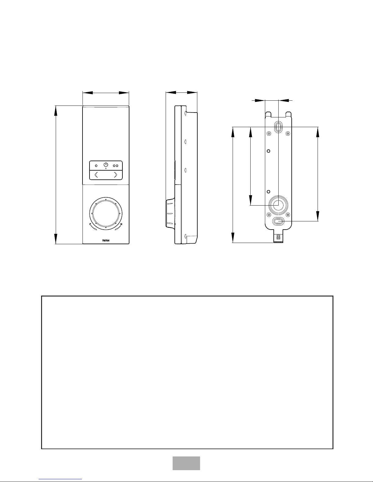
182
61
41
18
124
152
103
Digital Controller (Including Wall Fixing Bracket)
Professional installer Notes
In premises with metallic surfaces e.g. metal ceiling
panels, metal ducting and metallic insulating
materials, wireless transmissions MAY BE BLOCKED
from the control panel and prevent correct
operation of the shower.
To check the product suitability for commercial
and multiple installations, Please contact Triton’s
Specication Advisory Service on: 024 7637 2222
for guidance on installations.
Dimensions
Page 8
8
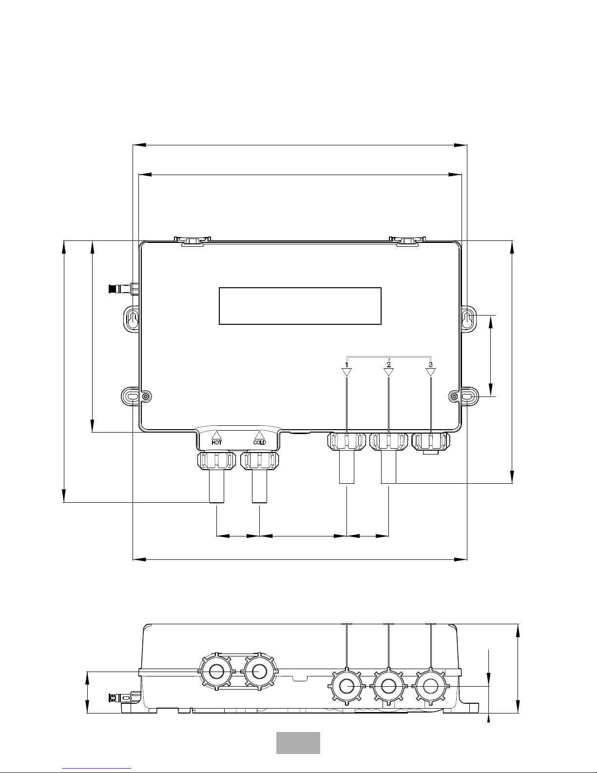
330
196
44 43
342
83
89
268
248
342
91
27.5
42.5
INLETS
OUTLETS
Dual Outlet Processor Unit
(High Pressure and Low Pressure)
Dimensions
Page 9
9
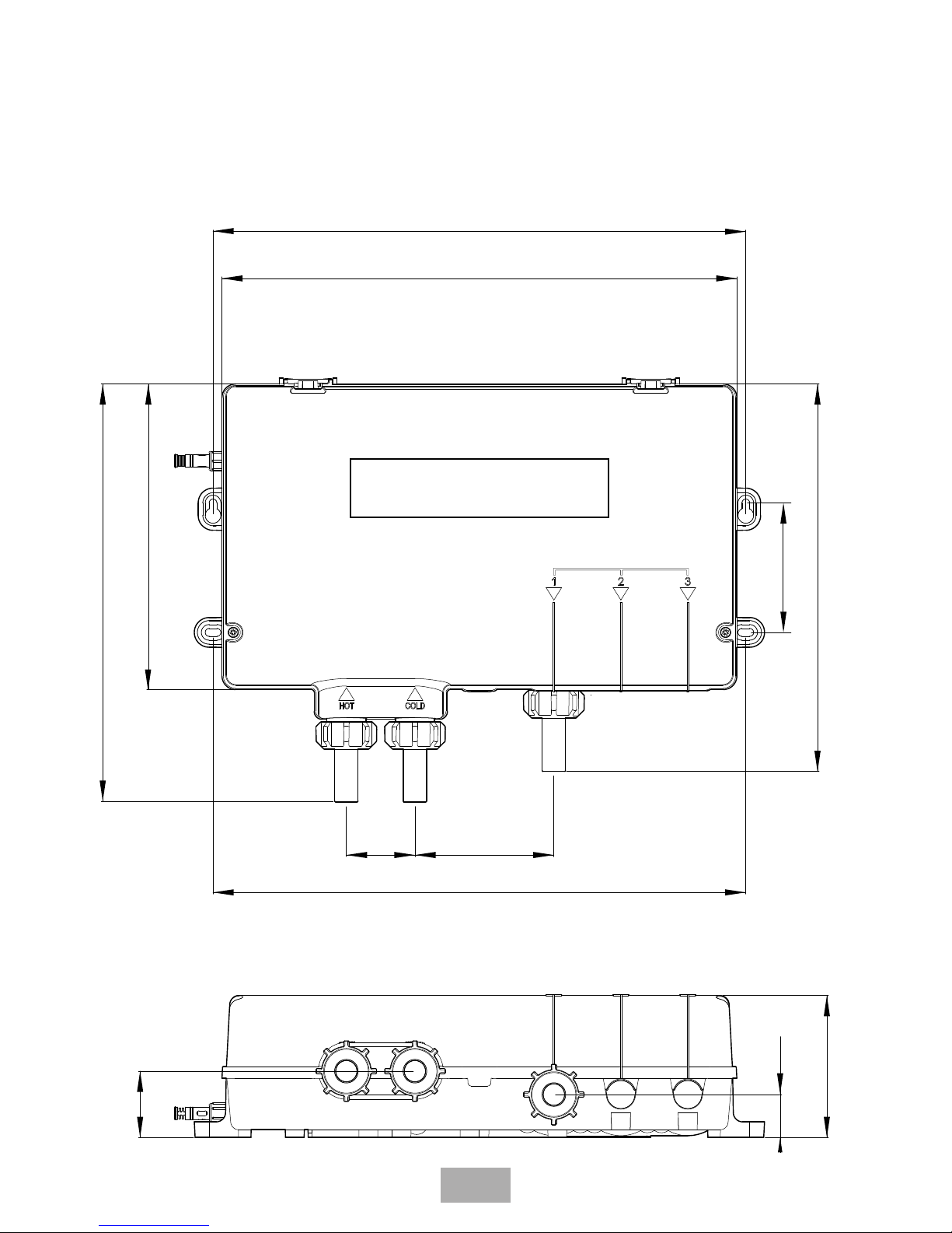
Dimensions
330
196
44
342
83
89
268
248
342
91
27.5
42.5
INLETS
OUTLETS
Single Outlet Processor Unit
(High Pressure and Low Pressure)
Page 10

10
Electrical
Mains Supply
Maximum Load
Water
Inlet Connections
Outlet Connections
Water Pressures
Maximum Static
Minimum Running
Supply Pressure
Differential
Temperatures
Hot water temperature
Cold water temperature
Ambient temperature
Showering temperature
adjustment range
Splashproof rating
Digital processor unit
Low pressure/gravity
system
230V 50Hz
125 W
15 mm push-fit
connectors**
15 mm push-fit
connectors**
100 kPa (1bar/10m head)
1 kPa (0.01bar/0.1m
head)
Nominally Equal
55°C - 65°C
1°C - 20°C
5°C - 40°C
32°C to 47°C*
IP24
Digital processor unit
High pressure
system
230V 50Hz
30 W
15 mm push-fit
connectors**
15 mm push-fit
connectors**
500 kPa (5 bar)
100 kPa (1 bar)
Nominally Equal
55°C - 65°C
1°C - 20°C
5°C - 40°C
32°C to 47°C*
IP24
*Max Temperature setting can be adjusted between 41°C and 47°C (factory set at 47°C)
Specication
**The Digital Mixer Shower is supplied with 15mm push t connectors, DO NOT use any
other type of tting
Page 11
11
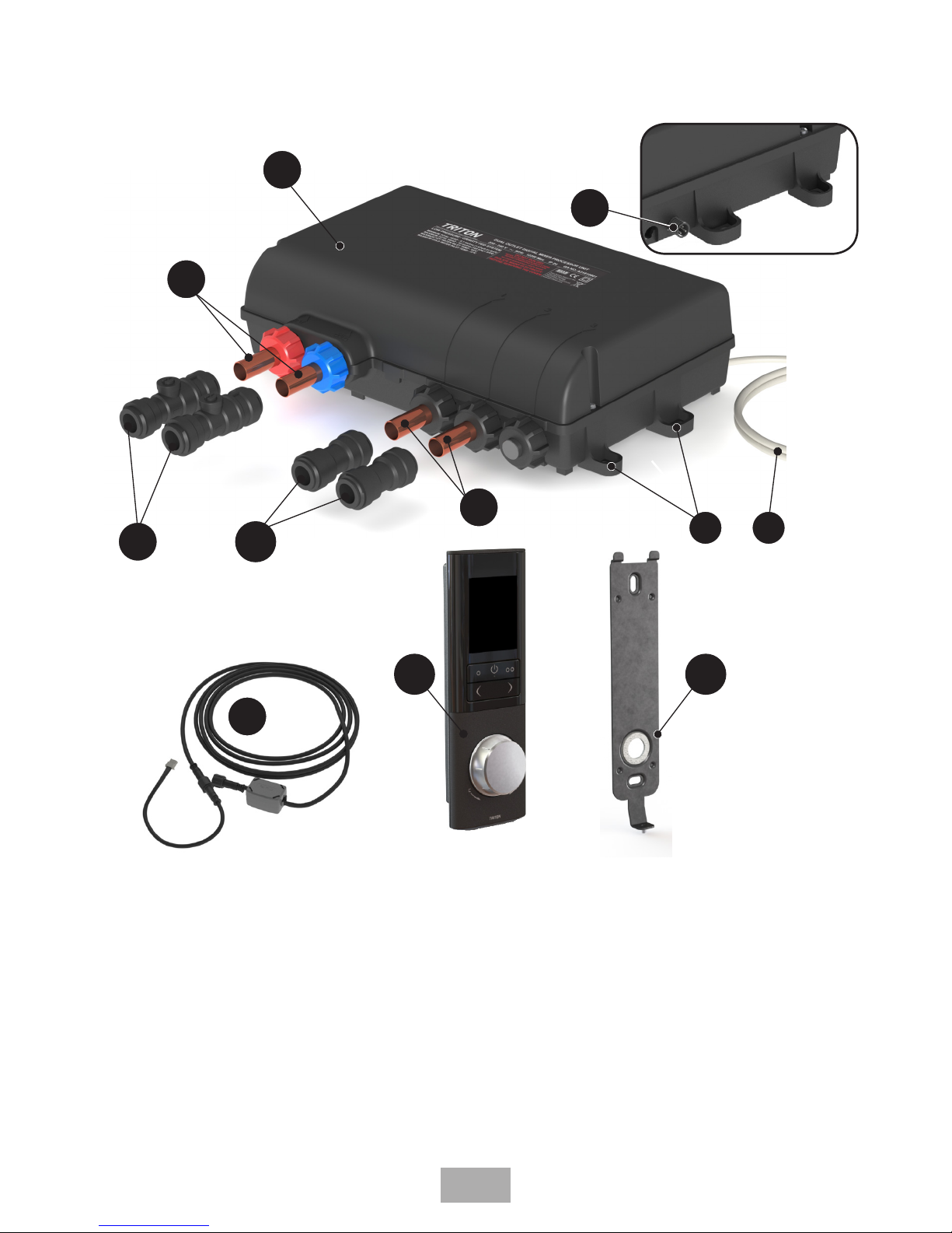
4
3
6
1
2
7
8
1. Digital Processor Unit Cover
2. Digital Processor Unit Fixing positions
3. Digital Processor Unit AC Power Lead
4. 15mm push fit connectors with Isolating valves
5. 15mm push fit connectors
6. Digital Processor Unit Inlets (HOT & COLD)
7. Digital Processor Unit Outlets*
8. Digital Processor Unit Data Cable connector
5
9. Digital Controller
10. Controller Fixing Bracket
11. 10m Data Cable
*(The number of outlets will vary depending on the configuration of the Digital Mixer
Shower purchased).
10
9
7
11
Main components
Page 12

12
The installation MUST BE carried out in accordance with these instructions, and
MUST BE undertaken by a qualied competent person.
The Digital Mixer Processor unit may be installed in a loft space, under the bath or in a
convenient cupboard space, provided there is enough room for maintenance. Safe and easy
access to the Digital Mixer Processor unit should be available at all times.
When planning the installation, if you are using the wired connectivity ensure that the
distance between the Digital Mixer Processor unit and Digital Control Panel is within the
range of the 10m data cable supplied, ensuring that the data cable routing is taken into
consideration.
Ensure that the Digital Mixer Processor unit is installed in a position that will minimise
the length of pipe run between the Digital Mixer Processor outlets and the showerhead/
accessory fittings.
The length of pipework running from the Digital Mixer Processor unit to the showerhead/
accessory fittings will have an effect on the showering temperature and the response time
when changing the showering temperature on the Digital Control Panel. The shorter the
length of pipework the better the Digital Mixer Processor unit will respond.
When installing the Digital Mixer Processor unit in an area not regularly accessed,
consideration for potential leaks must be taken into account.
While such events are unlikely, it is advisable to periodically check the installation for traces
of water on or around the processor unit. If possible site the Digital Mixer Processor unit in
a location where any leak would be contained or routed to avoid areas sensitive to water
damage.
Isolation valves are integrated into the push connection fittings supplied for the hot & cold
inlets, ensure that after installation these valves are left in the fully open position as failure
to do this will result in poor flow performance from the Digital Mixer Shower.
The shower MUST NOT be positioned where it will be subjected to freezing
conditions.
All pipe work MUST be rigidly supported to avoid any strain on the connections and
vibrations during use.
Long inlet pipework (dead-legs) should be kept to a minimum to avoid showering
temperature fluctuations
DO NOT connect the Digital Processor unit to a gravity hot supply and a mains cold supply
(or vice versa).
The pipework should be installed such that the flow is not significantly affected by other
taps and appliances being operated elsewhere on the premises.
There are no user-serviceable components beneath the cover of the Digital
Processor unit.
General installation
information
Page 13

13
High pressure system – Instantaneous hot water systems, e.g.
combination boilers (Fig.1)
The high pressure Digital Mixer Processor unit MUST be installed with a multipoint gas
water heater or combination boiler of a fully modulating design (i.e. where the water drawoff rate indirectly controls the gas flow rate to the burner).
A drop tight pressure reducing valve MUST be fitted if the supply pressures exceed 500kPa
(5 bar) running.
An expansion vessel MUST be fitted, (and regularly maintained) if any form of backflow
prevention device is fitted ie. PRV. This will ensure that excess expansion or pressure pulses
Important if using wireless connected devices
Metal objects such as steel baths, cold water storage tanks, hot water cylinders, radiators,
foil lined plaster board and even thick brick walls can all dramatically reduce the wireless
operational range.
Interference from other wirelessly controlled devices and radio signals can dramatically
reduce the ability of the wireless Digital Mixer Shower to maintain a good, consistent
wireless signal. This may include mobile phones, cordless phones, radio controlled toys,
wireless doorbells etc.
If you encounter difficulty whilst setting up the wireless connectivity of the Digital Mixer
Shower, ensure all other radio interference is temporary switched off.
Failure to follow these wireless connectivity guidlines can result in poor, intermittent or
failure of the communication between the Digital Control panel and Digital Mixer Processor
unit.
Typical suitable
installations
CH flow
Cold
mains
supply
Hot water
CH return
Processor Unit
Stop
tap
Mini
Expansion
vessel
Pressure
reducing valve
Combination
boiler
Kit
Control
panel
Fig.1
do not damage the product. This may already
be installed within the boiler (check with
manufacturer) and is in addition to the normally
larger central heating expansion vessel.
The layout and sizing of pipework MUST
be such that nominally equal inlet supply
pressures are achieved and the effects of other
draw-offs are minimised.
Combination boilers are not always able to
supply an adequate ow rate of hot water,
particularly in winter, Triton recommends
tting a ow regulator (supplied with
the Shower) into the Hot inlet of the High
Pressure Digital Processor Unit prior to
installation. Refer to the table for details
(see Fig.2).
Page 14

14
If using the Warm Up feature of the Remote Start/Stop Switch (optional accessory) with a
instantaneous water heater appliance the user may experience a brief temperature variation
upon restart. This is due to the way in which a combination boiler operates, such that the
boiler will turn off after the warm up process has been completed. When restarted, the
processing unit will release a cold slug of water followed by a hot slug as the hot water
supply stabilises.
High pressure system – Unvented mains pressure cylinders (Fig.3)
The high pressure Digital Mixer Processor unit MUST be installed with an unvented, stored
hot water cylinder.
For systems with no cold water take off after the appliance reducing valve, it will be
necessary to fit an additional drop tight pressure reducing valve when the mains pressure is
over 500kPa (5 bar). The drop tight pressure reducing valve MUST be set at the same value
as the unvented package pressure reducing valve.
Note: An additional expansion vessel (Fig.3) may be required if a second pressure
reducing valve is installed. This does not apply to packages with a cold take off
after the pressure reducing valve to the cylinder.
The layout and sizing of pipework MUST be such that nominally equal inlet supply
pressures are achieved and the effects of other draw-offs are minimised.
Typical suitable
installations
Flow
Regulator
Flow
Regulator
Housing
Inlet
Filter
O Ring
Seal
Inlet
Pipe
Hot
Inlet Nut
Fig.2
Boiler Rating Regulator
24 to 30kW 7 L/min
White/
Green
30 to 36kW 9 L/min
White/
Orange
36kW + None required
To t ow regulator
1. Unscrew the hot inlet nut and remove the inlet pipe, O ring seal, inlet lter and ow
regulator housing.
2. Fit the ow regulator into the ow regulator housing.
3. Ret the ow regulator housing, Inlet lter, O ring seal and inlet pipe, secure with the hot
inlet nut. Note: the hot inlet nut only requires to be hand tightened.
Page 15

15
Processor Unit
Kit
Service
valves
Balanced cold mains supply
Cold mains supply
Expansion
vessel
Pressure
reducing valves
Stop tap
Unvented
hot water
storage unit
Safety devices
not shown
Control
panel
Fig.3
Blender
valve
Flow
Cold mains
supply
Hot
water
Stop tap
Expansion
vessel
Pressure
reducing
valve
Return
Service valves
Processor unit
Boiler
Kit
Control panel
Fig.4
High pressure system – Mains pressurised thermal store systems
(Fig.4)
The high pressure system MUST be fitted with a tempering valve (blender valve).
The appliance must be capable of raising the temperature of the incoming water to a
minimum of 55°C and delivering a flow rate of not less than 8 L/minute
A drop tight pressure reducing valve MUST be fitted if the supply pressures exceed 500kPa
(5 bar) running.
An expansion vessel (shown in Fig.4) MUST be fitted, and regularly maintained, to ensure
the unit is not damaged by excess pressures. This may already be installed externally or
internally within the thermal store (check with thermal store manufacturer).
Typical suitable
installations
Page 16

16
100mm
minimum
Hot water
cylinder
Digital Mixer
Processor unit
Kit
Service
valves
Cold supply
Hot
supply
Cold
water
mains
supply
Drain
valve
Gate
valve
Other
draw-offs
Stop valve
Cold water
cistern
Digital
Control
Panel
Draw-off must point
down to avoid airlock
issues.
Alternative
supply (must
be below vent
pipe tee)
Fig.5
Only install the low-pressure
Digital Mixer Processor with a
gravity fed system. Never install
a high-pressure digital mixer
shower with a gravity fed system
Low pressure system – Gravity fed systems (Fig.5)
The low pressure Digital Mixer Processor unit MUST be fed from a cold water cistern and
hot water cylinder providing nominally equal pressures.
For the operation of the shower only, it is recommended that the cold water storage cistern
is capable of holding at least 114 litres (25 gallons). Where other hot and cold outlets are
likely to be in use simultaneously, the storage capacity should be increased to 228 litres (50
gallons) in accordance with BS EN 806.
IMPORTANT: Pipework layouts and connections MUST be such that other draw-offs will
not effect water supplies to the digital mixer processor unit, shared supplies may lead to air
locking or water starvation. It is therefore best practice to have independent hot and cold
supplies to the digital mixer processor unit.
If the hot water draw-off is incorrectly positioned, air may be drawn into the hot supply
from the vent pipe causing spluttering, temperature fluctuations at the showerhead.
Any draw-off for the processor unit must point DOWN (to avoid air-lock problems) and
must be BELOW the vent pipe tee.
Failure to correctly position the draw-off will result in poor performance or other problems
with the Digital Mixer Processor unit.
Typical suitable
installations
IMPORTANT: The minimum head for
operation of the Digital Mixer Processor
unit is 100 mm. For correct operation the
Digital Mixer Processor unit must not be
sited more than 5 metres away from the
hot water cylinder.
Page 17

17
The Digital Mixer Processor unit MUST only be positioned as shown.
The Digital Mixer Processor unit can be mounted on a horizontal surface in any orientation
(Fig.6).
When mounting on a vertical surface the processing unit outlet MUST be at the bottom
(Fig.7). Failure to position the unit correctly could result in a significant reduction in
performance.
Decide on the position for the Digital Mixer Processor unit. Position the Digital Mixer
Processor unit in a dry, well ventilated area.
The Digital Mixer Processor unit MUST always be positioned either flat on a suitable surface
or on a wall so that there is easy access for installation and maintenance.
Mark the four locating screw points for the base. If fixing to brick or a stud partition drill
and plug the wall. (The wall plugs provided are suitable for most brick walls — use an
appropriate masonry drill, but if the wall is plasterboard or a soft building block, you must
use suitable wall plugs and an appropriate drill bit). Secure the Digital Mixer Processor unit
in position using the 4 screws supplied (Fig.8)
Hot
& Cold
Inlets
Outlets
Ensure sufcient space is left surrounding
the processor unit to allow for pipework,
connections and
maintenance
Fig.6
Inlets and Outlets
MUST be
at the bottom
Fixing
Screws
(x4)
Fig.8
IMPORTANT
If wall mounting the Digital
Mixer Processor unit the out-
lets MUST always be at the
BOTTOM (Fig.7)
Fig.7
Mixer processor
installation
Page 18

18
If the Digital Mixer Processor unit is installed in a loft area the following requirements must
be met for future servicing purposes:
a. There must be no risk of the Digital Mixer Processor unit or water pipe becoming frozen.
b. The Digital Mixer Processor unit MUST NOT be covered with any form of insulating
material that may give rise to electrical circuits overheating during periods of high
ambient temperature.
c. A safe means of access must be provided into the loft, e.g. via a fixed loft ladder.
d. The Digital Mixer Processor unit MUST be installed in an accessible and safe location.
e. Ceiling joists MUST be adequately boarded to provide safe and unobstructed access to,
from and around the Digital Mixer Processor unit.
f. There MUST be adequate lighting in the loft for servicing purposes.
Note: If mounting the Digital Mixer Processor unit in a loft it is worth considering building a
catchment tank with an overflow pipe directed to an external point. In the unlikely event of
a problem occurring with the Digital Mixer Processor unit this will give a visual indication of
any failure.
Plumbing connections
Plumbing/Pipe installation to be carried out before electrical wiring
installation
DO NOT use jointing compounds on any pipe fitting for the installation.
DO NOT solder fittings near the shower unit as heat can transfer along pipework and
damage components.
Fig.9 shows the plumbing connections layout.
Hot
Inlet
Outlet Pipe work*
Inlet Pipe work
Cold Inlet
Fig.9
*The number of outlets connections will vary depending on the configuration of the Digital Mixer Shower
purchased.
Mixer processor
installation
Page 19

19
IMPORTANT: The fittings on the inlet and outlets are the push-fit type. The pipework must
be cut with a pipe cutter and all burrs and rough edges removed from the end of the tube.
The fittings can be used with copper and plastic pipe.
If using chrome plated copper pipe, remove the first 25 mm of plating completely from the
connecting surfaces. If not completely removed then the collet will not grip the pipe and
under pressure the pipe may be forced out.
Before completing the connection of the water supplies to the inlets of the Digital Mixer
Processor unit, flush out the pipework to remove all swarf and system debris.
1. Turn off the water supplies either at the mains stop valve or the isolating stop valve.
2. Having decided on the position of the unit and direction of pipe entry, complete the
pipework to the Digital Mixer Processor unit.
3. Check for leaks before connecting the pipework to the Digital Mixer Processor unit.
4. Insert the incoming pipework into the 15 mm push-fit connectors (Fig.10).
5. Check that the isolating valves on the inlet connectors are fully open (Fig.11).
For products that have more than one outlet then the above procedure of fitting the pipe
work will need to be conducted for each outlet.
All pipework should be insulated. DO NOT attempt to insulate or
cover the Digital Processor unit
15mm PUSH FIT
CONNECTOR
INCOMING
PIPE
ISOLATING VALVE
Fig.10
ON
OFF
Fig. 11
ISOLATING
VALVE
Mixer processor
installation
Page 20

20
Mixer processor
installation
Before any electrical work is attempted, ensure the electricity supply
is isolated at the mains switch.
Electrical installation may only be carried out by a qualied person.
Electrical connections
Connect the Digital Processor Unit AC Power Lead to a double pole 3Amp switched
fused spur (Fig.12), incorporated in the wiring circuit, in accordance with current wiring
regulations.
The 3Amp fused spur MUST be located in a dry, easily accessible position. Access to
the fused spur is required for servicing and maintenance
Neutral cable marked N Blue
Live cable marked L Brown
DO NOT switch on the electricity supply until all the pipe connections have been tested for
leaks and the commissioning procedure has been followed.
3A Switched
Fused Spur Box
Ring Main Cable
Digital Processor
Unit AC Power Lead
Fig.12
Page 21

21
Digital Mixer Shower
Fittings
Digital Control
Panel
Digital Mixer
Processor
Junction
Box
Hot Inlet
Cold Inlet
Outlet
3Amp switched
fused spur
MUST be easily accessible
To mains
electricity
supply
Digital Processor
to be within
10 metre range
Installation schematic
Examples of poor installation practices
DO NOT install the Digital Mixer Processor unit where it can become frozen
DO NOT install the Digital Mixer Processor unit where it can subjected to ambient
temperatures in excess of 40°C
DO NOT position the Digital Mixer Processor unit where maintenance access is poor or
unsafe
DO NOT install into a system where the cold water cistern holds less than 115 litres (230
litres if other outlets use the same cistern)
DO NOT install into a system where air locking could occur
DO NOT install the wireless Digital Control Panel in a position where communication with
the Digital Mixer Processor unit is poor e.g installed under a metal bath, in front of a metal
cistern, on foil backed plasterboard, outside of the 10 metre range.
DO NOT install the Digital Mixer Processor unit onto shared water supplies
DO NOT fit plastic pipework unless rigidly supported
DO NOT install the low pressure (gravity) Digital Mixer Processor unit less than 100mm from
the lowest level of water in the cistern
DO NOT install a high pressure/combination boiler Digital Mixer Processor unit to a low
pressure pumped gravity system
Mixer processor
installation
Page 22

22
The Digital Controller can be connected to the Digital Mixer Processor unit in two ways,
these are: a) 10 metre data cable or b), wirelessly using AA sized batteries.
The Digital Controller has been designed to allow for the installation within a shower cubical
or above a bath. The controller must be located whereby the user can start and stop the
shower immediately.
Select the desired method of communication and then choose a suitable location for the
Digital Controller.
If using wired connectivity, the distance between the Processor unit and Controller
MUST BE within the range of the 10m data cable.
Data cable installation (Wired Connectivity Only)
If connecting the Digital Controller to the Digital Mixer Processor unit using the data cable,
the first operation is connect the data cable (ferrite end, see fig.13) to the Digital Mixer
Processor unit.
On the ends of both the Data Cable and Processor Data Cable Connector are screw
connectors, which provide a water tight seal. To ensure that the connectors are correctly
assembled and sealed, ALIGN the two arrows on both connectors so that they point
towards one another, and follow the 3 steps in (Fig 13).
A 15mm diameter hole needs to be made within the showering area to allow for the data
cable connection (Fig.14).
Make sure there is enough slack cable at the controller end in order for the Digital Controller
to be removed should the need arise for future maintenance. Approx 150mm protruding
length should be sufficient (Fig 15).
Under NO circumstances should the data cable be extended or shortened. The data
cable must be connected with the ferrite end attached to the processor unit, as
not only will it impair the performance of the shower but it will also invalidate the
guarantee.
1
2
3
Fig. 13
124mm
Ø15mm
Hole
Wall Fixing
Wall Fixing
Data Cable
Fixing
Bracket
Fig. 14
Digital controller
installation
Ferrite
Processor Unit
Page 23

23
If the data cable is being routed through wall cavities, chased into
solid walls or surface mounted then appropriate trunking/conduit
MUST be used. Data cables MUST be fitted in such a way so that they
can later be removed for maintenance or servicing
150mm
Fig. 15
Fixing bracket installation
With the Digital Mixer Processor Unit located and the data cable routed it is now time to fit
the Digital Controller.
Using the fixing bracket and a spirit level locate the bracket in the desired location,
remembering to consider your cable routing position (Fig. 16).
Hold the fixing bracket in position and mark the top and bottom screw fixing holes A (Fig
16). Remove the bracket from the wall then drill and plug the wall for the fixing positions A.
(An appropriate drill bit should be used. If the wall is brick, plasterboard or a soft building
block, appropriate wall plugs and screws should be fitted).
Secure the mounting bracket to the wall using the appropriate fixings.
For Wired Connectivity Only: Whilst securing the mounting bracket to the wall, the data
cable must be pulled through so that approx 150mm protrudes from the wall, see (Fig 15).
A
A
Fig. 16
Digital controller
installation
Page 24

24
If installing the Digital Controller onto a tiled wall, always mount the
xing bracket on the surface of the tiles. NEVER tile up to the Digital
Controller.
Digital Controller fitting (Wired connectivity only)
Remove the Battery Compartment Cover on the rear of the Digital Controller by undoing
the two fixing screws (Fig 17).
Using a pair of side cutters remove from the Battery Compartment Cover the small plastic
tag as shown in (Fig 18).
Connect the 3 pin coupler of the Data Cable Connector Lead into the connector located on
the PCB within the Digital Controller. Taking care, push the connector lead in to the grooves
and slot of the Battery Compartment (Fig 19).
The 3 pin coupler can ONLY be tted one way into the PCB connector,
take care with assembly to avoid damage.
Fig. 19
Fig. 17
Fig. 18
Digital controller
installation
Page 25

25
Replace the Battery Compartment Cover and secure in place using the two fixing screws
previously removed.
Ensure that the Battery Compartment Cover sits flush with the rear housing of the Digital
Controller and that both retaining screws are tight (Fig 20). Do not over tighten the
screws.
Connect the Data Cable Connector Lead from the Digital Controller to the Data Cable
protruding from the fixing bracket (Fig 21).
Fig. 20
On the ends of both the Data Cable and Data Cable Connecting Lead are screw connectors,
which provide a water tight seal. To ensure that the connectors are correctly assembled and
sealed, ALIGN the two arrows on both connectors so that they point towards one another,
and follow the 3 steps in (Fig 22).
Fig. 21
1
2
3
Fig. 22
Digital controller
installation
Page 26

26
Fig. 24
DO NOT turn on the electricity supply to the Digital Mixer Shower
until commissioning
Digital Controller fitting (Wireless Connectivity Only)
Triton recommends that any drilling of holes to secure the wireless Digital Controller is NOT
undertaken until after commissioning, as the exact final location will need to be tested to
ensure that a good, consistent wireless signal is present between the Digital Controller and
Digital Mixer Processor unit.
The approximate position of the wireless Digital Control Panel should be no more than 10
metres from the Digital Mixer Processor unit.
Remove the Battery Compartment Cover on the rear of the Digital Controller by undoing
the two fixing screws (Fig 17).
Fit 3 x AA sized batteries (not supplied) into the Digital Controller as shown in Fig 25.
TRITON recommend the use of Lithium batteries to maximise
battery life of the Digital Controller.
Digital controller
installation
Offer the Digital Controller up to the Fixing Bracket. Whilst doing so push the excess Data
Cable/Data Cable Connection Lead through the hole within the fixing bracket, and back
into the wall cavity.
Fit Digital Controller cut-outs over the Bracket Fixing Lugs (Fig 23) and slide down into
place. Secure with the single screw at the bottom of the Digital Controller (Fig 24). Do not
over tighten the screw.
Control Panel
Cut-Outs
Bracket
Fixing Lugs
Fig. 23
Page 27

27
Make sure the tting of the batteries is carried out correctly
otherwise the PCB within the Digital Controller could be damaged.
Replace the Battery Compartment Cover and secure in place using the two fixing screws
previously removed.
Ensure that the Battery Compartment Cover sits flush with the rear housing of the Digital
Controller and that both retaining screws are tight (Fig 20). Do not over tighten the
screws.
Offer the Digital Controller up to the Fixing Bracket.
Fit Digital Controller cut-outs over the Bracket Fixing Lugs (Fig 23) and slide down into
place. Secure with the single screw at the bottom of the Digital Controller (Fig 24). Do
not over tighten the screw.
Digital controller
installation
1 2
3
Fig. 25
Page 28

28
While the Digital Mixer Shower is in commissioning mode all other
functionality is locked out.
Ensure that the isolating valves on the hot and cold inlets connectors are fully on (Fig.11).
Turn on the water supplies and check the entire installation for water leaks.
Commissioning MUST be carried out with suitable pipework/hose attached to the shower
outlet and with the outlet directed to waste.
Commissioning is to ensure water is purged through the unit and any air is dispelled from
the system.
DO NOT run the low pressure Digital Mixer Shower (Pumped version) without water.
Failure to commission the Digital Mixer Shower correctly could cause
long term damage to the shower.
Turn on the electrical supply to the Digital Mixer Processor unit.
Wireless connectivity only
With batteries fitted into the Digital Controller, electricity supply to the Digital Processor
unit turned on, the wireless connectivity between the Digital Controller and Digital Mixer
Processor unit will be automatically undertaken.
If however either of the messages in Fig. 26 are displayed on the Digital Controller
permanently then wireless connectivity should be undertaken manually.
To manually connect the Digital Controller with Digital Mixer Processor unit, ensure that fully
charged batteries are fitted into the Digital Controller.
1 Isolate the electricity supply to the Digital Mixer Processor Unit
2 After at least 1 minute restore the electricity to the Digital Mixer Processor Unit
3 Within 2 minutes press and hold the ow control buttons together and hold
themdown for at least 5 seconds.
4 Wireless connectivity should now be reset, if this does not resolve the loss of
connection, this process can be repeated.
ºC
4
1
Lost Signal
Symbol
Connection Error!
Fig. 26
Commissioning
Page 29

29
Procedure
The message in Fig.28 will be displayed on the Digital Controller. To begin the
commissioning procedure, press the ‘Start/Stop’ button (Fig.27).
Allow the unit to run for five minutes to dispel any air in the system and to prime both
supplies to the unit.
Press and hold outlet 2 ( symbol) for 5 seconds when the commissioning process is
complete, this will set the Digital Mixer Shower into normal operation mode.
It may be necessary to repeat the commissioning procedure , i.e following servicing or
maintenance.
This can be reactivated from the configuration menu. Refer to the ‘Settings and
configuration’ section within the user guide.
ENSURE that the position of the wireless Digital Controller is within a
10 metres range of the Digital Mixer Processor unit.
If the symbols in Fig. 26 are still displayed, then a repositioning of the Digital Controller
is required. Ensure that a good, consistent wireless signal is present between the Digital
Controller and Digital Mixer Processor unit.
During the commissioning mode, the pump is disabled (LP gravity version only), Outlet 1 is
opened, flow control is set to maximum and temperature control is set in mid position.
DO NOT run the low pressure Digital Mixer Shower (Pumped version)
without a water supply for longer than 5 minutes.
Flow Control
Buttons
Fig. 27
Start/Stop
Button
Commissioning
Fig. 28
Commissioning
Mode
PRESS TO
START SHOWER
HOLD FOR
5 SECONDS
WHEN COMPLETE
Page 30

30
Press the start
button to activate
the shower
Alternatively, select
your preferred preset,
‘Relax / User 1’ ( ) or
‘Energise / User 2’ ( )
Adjust the ow rate
with the decrease ( )
and increase ( )
buttons.
Adjust the temperature
with the temperature
dial
Select between your two outlets*
using the outlet buttons ( ) /
( )or press both to run them at
the same time
1
To power down the shower, press
the start button , or
alternatively deselect the outlets
using buttons ( ) / ( )
2 3
4 5
Quick start
(*outlet selections are only available on multi outlet product versions)
Page 31

31
If the Digital Mixer Processor unit is dismantled for any reason during servicing or
maintenance, then it MUST be inspected to ensure there are no leaks, it is also advised to
follow the commissioning procedure to ensure no air has become trapped during the work.
Cleaning
Many household cleaners contain abrasive and chemical substances, and should not be
used for cleaning the Digital Controller or any chrome plated fittings. It is recommended
that your Digital Mixer Shower system is cleaned regularly with warm, soapy water using a
micro bre cleaning cloth (eg: E-cloth) or sponge ONLY.
DO NOT use a general purpose cleaning cloth (eg: J-cloth) dish cloth or scourer.
DO NOT use abrasive or aggressive chemical cleaning products as this may aect the
product surface nish and invalidate your guarantee..
It is recommended that the filter is periodically cleaned in order
to maintain the performance of the shower. It is essential that this
operation is carried out by a competent person.
Cleaning the filters
Using an appropriate flat bladed screwdriver, isolate both the hot and cold inlet valves
(Fig. 11).
Isolate the electricity supply to the Digital Mixer Processor unit.
Unscrew the inlet nut and remove the inlet pipe, O ring seal, ow regulator housing/Inlet
lter.
Remove the inlet lter from the ow regulator housing (Fig. 28) and wash thoroughly under
running water to remove all debris.
Ret the ow regulator housing/Inlet lter, O ring seal and inlet pipe, secure with the inlet
nut. Note: the inlet nut only requires to be hand tightened.
Flow Regulator
Housing/Inlet Filter
O Ring
Seal
Inlet
Pipe
Inlet Nut
Flow Regulator
Housing/Inlet Filter
Non Return
Valve
Fig.28
General
maintenance
Page 32

32
8
2
4
5
6
7
15
11
14
12
10
13
1
3
9
Spare parts
Page 33

33
Ref. Description Part No.
1. Temperature Control Valve
Low pressure ....................................................................................................... 83316750
High pressure ..................................................................................................... 83316760
2. Digital Mixer Processor PCB
Single Outlet ........................................................................................................ 7073756
Multi Outlet ........................................................................................................... 7073763
3. Temperature Control Motor ........................................................... 22013594
4. Flow Control Valve ....................................................................................... 83316770
5. Flow Control Motor .................................................................................... 22013595
6. Thermistor Assembly .............................................................................. 83316780
7. Solenoid Assy & O Ring Seals ........................................................ 83316800
8. Pump Assembly .............................................................................................. 83316790
(Low Pressure Digital Mixer Processor Only)
9. Check Valve and Inlet Filter Pack .............................................. 83316810
10. Digital Controller
Black Finish ............................................................................................................ 83316820
White Finish .......................................................................................................... 83316830
Cloud Grey Finish ............................................................................................ 83316840
11. Battery Cover & Screws Assembly
Black Finish ............................................................................................................ 83316720
White Finish .......................................................................................................... 83316710
Cloud Grey Finish ............................................................................................ 83316730
12. Digital Controller Fixing Bracket ............................................... 83316740
13. Digital Controller Fixing Screw ................................................... 20801180
14. 10m Data Cable ............................................................................................... 2160636
15. Data Cable Connection Lead .......................................................... 2160634
Spare parts
Page 34

34
Digital Mixer
Shower will not
turn on/no water
flow
Interrupted power
supply
Blown fuse or circuit breaker. Check
supply Renew or reset fuse or circuit
breaker. If it fails again, consult a
qualified electrician
Power cut? Check other appliances and
if necessary, contact local Electricity
Supply Company
Batteries in Digital
Control panel are flat
(wireless only)
Fit new batteries, refer to ‘Digital
Control Panel Installation’
Digital Control panel is
installed out of range
(wireless only)
Reposition the Digital Control Panel,
refer to ‘Digital Control Panel
Installation’
Inlet Isolating valves
not fully open
Check if isolating valves are fully open
Inlet filters or check
valves blocked
Check for a blockage, refer to
‘Maintenance’
Air lock in water
supplies (LP unit
only)
Purge air from hot and cold supplies to
the connectors on the mixer unit, see
‘Commissioning’
Failure of either water
supply
Check water elsewhere in the house
and, if necessary, contact the local water
company
Loss of wireless
connection between
control Panel and
Processor unit
(wireless connectivity
only)
Repeat wireless connectivity process, see
‘Commissioning’
Unit malfunction Contact Triton Customer Service
Problem/Symptom Cause Action/Cure
If any maintenance is required then it MUST be carried out by a competent trade person
or a Triton Engineer. ENSURE that the underlying cause of malfunction is resolved before
replacing any parts
IMPORTANT - Isolate the electricity supply and remove the circuit
fuse before attempting any fault diagnosis inside the Digital Mixer
processor
Fault diagnosis
Page 35

35
Water too cool
or cold
Temperature setting
too low
Increase temperature via rotary
temperature control. See ‘Quick Start’
‘Max Shower Temp’
setting set to low
Increase Max Shower Temp setting,
refer to ‘Configure Settings’ in the user
manual
Supply temperature
below 50°C
Set system temperature to a minimum of
55°C, see ‘Specification
Water pressure above
maximum specified or
imbalanced
Check water pressures are normally equal,
refer to ‘Specification’
Combination boiler
cutting in/out
Check the use of flow regulators, see
‘Typical Suitable Installations’
Insufficient supply of
stored hot water
Check storage capacity of hot water, see
‘Typical Suitable Installations’
Air lock in Digital
Mixer Processor unit
(LP unit only)
Prime to remove air from the mixing unit,
see ‘Commissioning’
Inlet supply
connection reversed
Check and if necessary correct, see
‘Digital Mixer Processor Installation’
Outlet pipe run is too
long
Ensure outlet pipe is thermally lagged,
see ‘Digital Mixer Processor Installation’
Low Flow Rate Flow setting too low
Increase flow by pressing the flow
increase button, see ‘Quick Start
Inlet Isolating valves
not fully open
Check if isolating valves are fully open
Blockage in inlet filters
or check valves
Check for a blockage, refer to
‘Maintenance
Blockage in pipework
Turn off the shower and consult a suitably
competent plumber
Blocked showerhead
or hose
Clean sprayplate or replace blocked hose
Inlet water pressure
low
Check if sufficient water pressure, see
‘Specifications
Problem/Symptom Cause Action/Cure
Fault diagnosis
Page 36

36
Low Flow Rate
Air lock in Digital
Mixer Processor unit
Prime to remove air from the mixing unit,
see ‘Commissioning’
Hot inlet flow
regulator not suitable/
wrongly fitted
Check and refer to ‘Typical Suitable
Installation’
Shower stops
during showering
Maximum showering
time reached
Restart the shower by pressing the ‘Start’
button, refer to ‘Configure Settings’ in
the user manual
Loss of wireless
connection between
digital Control Panel
and Processor unit
(wireless connectivity
only)
Repeat wireless connectivity process, see
‘Commissioning’
Loss of either water
supply
Check water elsewhere in the house
and, if necessary, contact the local water
company
Check that water is available to the
shower when other outlets are in use
Wait for stored water to reach
temperature
Air lock in Digital
Mixer Processor unit
Check for correct installation, repeat
priming to remove air from the mixing
unit, see ‘Commissioning’
Combination boiler
cutting in/out
Check the use of flow regulators, see
‘Typical Suitable Installations’
Digital Control
Panel is not very
responsive
Loss or Poor wireless
signal between Digital
control Panel and
Processor unit
Check wireless connectivity, see
‘Commissioning’
Unit malfunction Contact Triton Customer Service
Shower Pulsing
(HP mixer unit on
combination boiler)
Water supply
temperature too low
Increase domestic hot water
temperature
Unbalanced water
pressures
Fit a pressure reducing valve in the cold
supply to the mixer and set to the same
pressure as the hot supply
Problem/Symptom Cause Action/Cure
Fault diagnosis
Page 37

37
Noise
Air lock in Digital
Mixer Processor unit
Check for correct installation, repeat
priming to remove air from the mixing
unit, see ‘Commissioning’
Water hammer
Ensure all pipework is securely fixed, see
‘General Installation Information’
Unit malfunction Contact Triton Customer Service
Problem/Symptom Cause Action/Cure
Fault diagnosis
Page 38

38
WEEE Directive – Policy Statement
As a producer and a supplier of electric showers, Triton Showers is committed to the protection of the environment
via our own environmental policy and the compliance with the WEEE directive.
Triton Showers is fully registered with the Environment Agency under the following schemes:
Repic: Producers take-back scheme (PTS), registration number WEE/EJ3466QV
Valpak: Distributor take-back scheme (DTS), registration number 9659
All our electric products are labelled accordingly with the crossed out wheeled bin symbol. This indicates, for
disposal purposes at end of life, that these products must be taken to a recognised collection points, such as
local authority sites/local recycling centres; this will be free of any charges. Do not return to Triton Showers.
Batteries
Spent batteries should NOT be disposed of with your normal household waste
NEVER dispose of batteries in fire as this may cause them to explode
ALWAYS dispose of batteries in an environmentally friendly manner and in accordance
with local regulations
Disposal and
recycling
Page 39

39
In the event of a product fault or complaint occurring,
the following procedure should be followed:
DO NOT REMOVE THE PRODUCT
1. Telephone Customer Service on 024 7637 2222 having
available your details including post code, the model number
and power rating of the product, together with the date of
purchase and, where applicable, details of the particular fault.
2. If required, the Customer Service Advisor will arrange for a
quali ed engineer to call.
3. All products attended to by a Triton service engineer must be
installed in full accordance with the Triton installation guide
applicable to the product. (Every product pack contains an
installation guide, however, they can also be downloaded free at
www.tritonshowers.co.uk).
4. Our engineer will require local parking and if a permit is
required, this must be available to the engineer on arrival at the
call.
5. It is essential that you or an appointed representative (who must
be over 18 years of age) is present for the duration of the service
engineer’s visit. If the product is in guarantee you must produce
proof of purchase.
6. Where a call under the terms of guarantee has been booked
and the failure is not product related (i.e. scaling and furring,
incorrect water pressure, pressure relief device operation or
electrical/plumbing installation fault) a charge will be made. A
charge will also be issued if nobody is at home when the service
engineer calls or adequate parking/permit is not available.
7. If the product is no longer covered by the guarantee an
up-front xed fee will be charged before the site visit.
8. Your receipt must be retained as proof of purchase. Should proof
of purchase not be available on an ‘in-guarantee’ call, or should
the service engineer nd that the product is no longer under
guarantee, the engineer will charge the same xed price and the
customer will be expected to pay the engineer before he leaves.
If payment is not made on the day an administration charge will
be added to the xed charge.
9. If a debt is outstanding from a previous visit, or from any other
Triton purchase, Triton reserves the right to withhold service until
the debt has been settled.
10. Triton takes the health, safety and wellbeing of its employees
very seriously and expects customers to treat all staff members
with respect. Should any employee feel threatened or receive
abuse, either verbally or physically, Triton reserves the right to
withhold service.
Replacement Parts Policy
In line with AMDEA guidelines, Triton retains functional spares
for as long as there is a market for them and in most cases, well
beyond. Due to the vast array of product types, the life cycle of
products can vary and therefore so can the length of time parts
can be supplied. Spare parts can be ordered via our online spare
parts store or by telephoning Triton Customer Service Spares
Department on 024 7637 2222. Payment should be made by
credit / debit card (excluding American Express or Diners Card).
Payment can also be made by pre-payment of a pro-forma
invoice, by cheque or postal order.
Telephone orders are based on information given during
the call. Before contacting Triton, please verify your
requirements using the Information contained in the
user guide. Triton cannot accept liability for incorrect part
identi cation.
TRITON STANDARD GUARANTEE
With the exception of accessories, Triton guarantee the
product against all manufacturing defects for a period of
5 years (for domestic use only) from the date of purchase,
provided that it has been installed by a competent person in
full accordance with the tting instructions.
All accessories such as shower heads, hoses and riser rails
carry a 1 year parts only guarantee against manufacturing
defects.
Any part found to be defective during this guarantee period
we undertake to repair or replace at our option without
charge, so long as it has been properly maintained and
operated in accordance with the operating instructions and
has not been subject to misuse or damage. This product must
not be taken apart, modi ed or repaired except by a person
authorised by Triton. This guarantee applies only to products
installed within the United Kingdom and does not apply to
products used commercially. This guarantee does not affect
your statutory rights.
What is not covered:
1. Breakdown due to:
a) use other than domestic use by you or your resident
family;
b) wilful act or neglect;
c) any malfunction resulting from the incorrect use or
quality of electricity, gas or water or incorrect setting of
controls;
d) failure to install in accordance with this installation
guide.
2. Claims for missing parts once the product has been
installed.
3. Repair costs for damage caused by foreign objects or
substances.
4. Total loss of the product due to non-availability of parts.
5. Compensation for loss of use of the product or
consequential loss of any kind.
6. Call out charges due to an abortive visit or where no fault
has been found with the appliance.
7. The cost of repair or replacement of isolating switches,
electrical cable, fuses and/or circuit breakers or any other
accessories installed at the same time. Replacement of the
Pressure Relief Device that only activates when the shower
outlet is blocked is also excluded.
8. The cost of routine maintenance, adjustments, overhaul
modi cations or loss or damage arising therefrom,
including the cost of repairing damage, breakdown,
malfunction caused by corrosion, furring, frost or
exposure to freezing conditions.
9. Call out charges where the water supply cannot be
isolated, this includes consequential losses arising from
unserviceable supply valves.
For the latest Terms & Conditions please see:
www.tritonshowers.co.uk/terms
UK SERVICE POLICY
Guarantee and
service policy
Page 40

Triton Showers
Triton Road
Nuneaton
Warwickshire
CV11 4NR
Installer Hotline:
+44 (0) 2476 378 320
Customer Services:
+44 (0) 2476 372 222
Email:
technical@tritonshowers.co.uk
enquire@tritonshowers.co.uk
Website:
tritonshowers.co.uk
Brochure enquiries:
+44 (0) 24 7632 4460
Triton Showers is a division of
Norcros Group (Holdings) Limited.
Triton Showers, Triton Road, Nuneaton,
Warwickshire CV11 4NR
It is our policy to improve the design and specification of our products and we reserve the right to depart from the design
given without prior notice.
#rstthing
 Loading...