

Page 1

Using BathyPro™
User’s Manual
Software documentation through v1.6
June 2004
Page 2

Copyright Notice
This software is copyrighted and licensed for use on one computer per copy. Triton
Elics International grants permission to the purchaser to make a limited number of
copies of the program for backup purposes. Additional reproduction of the programs or
this manual is a violation of the copyright law.
The licensee is bound by the terms and conditions set forth in the Software License
Agreement and Limited Warranty that accompanies this document.
BathyPro™, Isis
Suite™, TriPort™, Q-MIPS™, VISTA™, TriCAS™, ROVFlight™, A-B™, and
Isis
The following are copyrights of their respective companies or organizations:
WinRT Registry: BlueWater Systems
HawkEye, Imagine 128: Number Nine Visual Technology Corp.
The following are trademarks and/or registered trademarks of their respective
companies or organizations:
EXB-8500, EXB-8505XLI, EXB-8500C, EXB-8205: EXABYTE Corporation
Windows, Windows NT, Windows 95, MS-DOS: Microsoft Corporation
Pentium, MMX: Intel Corporation
Adaptec AHA 1505 and AHA 2940: Adaptec, Inc.
Klein 5000, Klein 2000, Klein 595: Klein Associates, Inc.
DF-1000: EdgeTech
Echoscan, Echotrac: Odom Hydrographic Systems, Inc.
ADS-640, GSP-1086, EPC-9082: EPC Labs, Inc.
Sentinel Scribe: Rainbow Technologies North America, Inc.
mach64: ATI Technologies, Inc.
HYPACK: Coastal Oceanographics, Inc.
International Business Machines
1200C, DesignJet 650C: Hewlett-Packard
1086, 8300, 980x plotters: EPC
TDU 1200, 850, 2000 plotters: Raytheon
195 (same as Dowty 195, Ultra 195 and Ultra 200): Waverley
InstallShield: InstallShield Corporation
All other brand or product names mentioned in this manual are trademarks or registered
trademarks of their respective companies or organizations.
®
Sonar Pipeline, DelphSeismic®, DelphMap®, Survey Office™, Hydro
Convert CD™, are trademarks of Triton Elics International, Inc.;
®
Sonar is a registered trademark of Triton Elics International, Inc.
Page 3

Safety Precautions
When working with the overall system
1. Before handling components inside your computer system, exit all applications
and shut down the operating system in accordance with procedures applicable
to them.
2. Turn off the power to the computer and disconnect all cables that may be
feeding electrical power to the system you will be working on.
3. Wear a grounded, anti-static wrist-strap. This is especially important if you are
removing, replacing, or installing a printed circuit board of any kind.
Failure to adhere to these and other safety precautions mentioned in the manual could
result in harm to property or personnel!
When working with magneto-optical cartridge disks
• Please refer to the Appendix entitled “Mass Storage Options” for important details
covering the handling of M-O disks!
• Never boot your system with a writable M-O cartridge inserted into the drive!
• Use magneto-optical media that has 512 bytes per sector, not 1024 bytes per
sector, and use the AFDisk software utility to format magneto-optical media. Never
use Windows 95 to format M-O media!
Please adhere to the hardware and software precautions mentioned
below. In addition, observe all safety precautions mentioned in this
manual.
Triton Elics Internatonal
125 Westridge Drive
Watsonville, CA 95076
USA
support@tritonelics.com
(831) 722-7373
© 1991-2004 Triton Elics International, Inc. All rights reserved. Printed in the U.S.A.
Page 4

SOFTWARE LICENSE AGREEMENT
By opening this package, you agree to be
bound by the terms of this Agreement, which
include the software license and the limited
warranty. This Agreement applies to you and
any subsequent licensee of this software
program. If you do not accept or agree to the
terms of this Agreement, do not open this
sealed package. Promptly return the
unopened package to TRITON ELICS for a
refund. However, no refund or replacement
will be given if the sealed envelope
containing the SOFTWARE Sentinel and
Manual has been opened or if any of the
components of the product (including the
software sentinel) are missing. Grant of
license for the software product and full title
and ownership of the hardware product shall
not transfer to the Buyer until the purchase
price, plus any interest or fees resulting from
late payments or pre-arranged terms, has
been received in full by the Seller.
1. GRANT OF LICENSE: TRITON ELICS
grants you the right to use the enclosed
TRITON ELICS software product in the
manner provided below.
YOU MAY:
• Use one copy of the TRITON
ELICS software products identified
above on a single computer.
• Make one (1) copy of the program
in machine-readable form solely for
backup purposes, provided that
you reproduce all proprietary
notices.
• Transfer the SOFTWARE and user
documentation on a permanent
basis provided you retain no copies
and the recipient agrees to the
terms of this Agreement.
YOU MAY NOT:
1. Reverse engineer, decompile, modify or
disassemble the SOFTWARE except to the
extent such foregoing restriction is expressly
prohibited by applicable law.
Remove any proprietary notices, labels, or
marks on the program, documentation, or
program disk.
2. UPGRADES. SOFTWARE and
documentation upgrades are provided free of
charge for one year from the date of
shipment. If the SOFTWARE is an upgrade,
you may use or transfer the SOFTWARE
only in conjunction with upgraded product.
You may use that upgraded product only in
accordance with this License.
3. COPYRIGHT. The SOFTWARE (including
any images, “applets,” animations, video,
audio, music, and text incorporated into the
SOFTWARE) is owned by TRITON ELICS
and is protected by United States copyright
laws and international treaty provisions.
4. TECHNICAL SUPPORT. Technical
Support is available by phone, fax, modem,
Triton Elics bulletin board service or Internet
free of charge during warranty period.
MARISAT charges are invoiced at cost plus
twenty percent.
5. EXPORT RESTRICTIONS. You agree
that neither you nor your customers intends
to or will, directly or indirectly, export or
transmit the SOFTWARE or related
documentation and technical data to any
country to which such export or transmission
is restricted by any applicable U.S.
regulation or statute, without the prior written
consent, if required, of the Bureau of Export
Administration of the U.S. Department of
Commerce, or such other governmental
entity as may have jurisdiction over such
export or transmission.
Page 5

LIMITED WARRANTY
TRITON ELICS warrants that (a) the
SOFTWARE will perform substantially in
accordance with the accompanying written
materials for a period of one (1) year from
the date of shipment and (b) any hardware
accompanying the SOFTWARE will be free
from defects in materials and workmanship
under normal use and service for a period of
one (1) year from date of shipment.
CUSTOMER REMEDIES. TRITON ELICS’s
entire liability and your exclusive remedy
shall be, at TRITON ELICS’s option, repair
or replacement of the SOFTWARE or
hardware that does not meet TRITON
ELICS’s Limited Warranty. Warranty service
is F.O.B. TRITON ELICS’s Watsonville
facility. All shipping and insurance costs are
paid by buyer. On-site Customer Service and
Warranty Repair (including travel hours,
transportation, lodging and meals) may be
provided by TRITON ELICS, at its own
discretion, to Buyer at cost plus twenty
percent. However, actual labor hours to
provide this service or repair will be free of
charge to Buyer. This Limited Warranty is
void if failure of the SOFTWARE or hardware
has resulted from accident, abuse, or
misapplication. Any replacement
SOFTWARE or hardware will be warranted
for the remainder of the original warranty
period or thirty (30) days, whichever is
longer.
NO OTHER WARRANTIES. Except for the
above express limited warranties, TRITON
ELICS makes no warranties, expressed,
implied, statutory, or in any communication
with you, and TRITON ELICS specifically
disclaims any implied warranty of
merchantability or fitness for a particular
purpose. TRITON ELICS does not warrant
that the operation of the program will be
uninterrupted or error free. Some
states/jurisdictions do not allow the exclusion
of implied warranties, so the above
exclusions may not apply to you. This limited
warranty gives you specific legal rights. You
may have others, which vary from
state/jurisdiction to state/jurisdiction.
NO LIABILITY FOR CONSEQUENTIAL
DAMAGES. To the maximum extent
permitted by applicable law, in no event shall
TRITON ELICS be liable for any damages
whatsoever (including, without limitation,
damages for loss of business profits,
business interruption, loss of business
information, or any other pecuniary loss)
arising out of the use of or inability to use
this TRITON ELICS product, even if TRITON
ELICS has been advised of the possibility of
such damages. Because some states/
jurisdictions do not allow the exclusion or
limitation of liability for consequential or
incidental damages, the above limitation may
not apply to you.
U.S. GOVERNMENT RESTRICTED
RIGHTS. The SOFTWARE and
documentation are provided with
RESTRICTED RIGHTS. Use, duplication, or
disclosure by the Government is subject to
restrictions as set forth in subparagraph (c)
(1) and (ii) of the Rights in Technical Data
and Computer Software clause at DFARS
252.227-7013 or subparagraphs (c) (1) and
(2) of the Commercial Computer Software—
Restricted Rights at 48 CFR 52.227-19, as
applicable. Manufacturer is Triton Elics
International, Inc., 125 Westridge Drive,
Watsonville, CA 95076. If you acquired this
product in the United States, this Agreement
is governed by the laws of California. If this
product was acquired outside the United
States, then local law may apply.
Page 6
Preface
This book is intended for users who wish to use the BathyPro™ application
program from Triton Elics to process XTF data.
How this book is Organized
The BathyPro techniques for processing multibeam data differ from the
techniques for processing single-beam data. Accordingly, the major division of
the book is along the lines of multibeam and single-beam processing techniques.
Patch testing is an optional task and is only applicable to multibeam
echosounders.
This book has three major divisions - Part I: Multibeam Processing, comprised of
Chapters 2 through 4, which is the bulk of the book; Part II: Single-Beam
Processing, which has but a single chapter in it, Chapter 5; and Part III:
Calibration of a Multibeam Echosounder, where the Patch Test routine is
described.
Because the software explained in this book runs on Windows NT, Windows
2000, and Windows XP, you should know how to work in those environments so
you can find, run, and exit BathyPro.
We use these conventions in the book:
Denotes a warning or caution .
Denotes an import ant statement, tip, or hint.
Page 7

PREFACE.........................................................................................................................6
HOW THIS BOOK IS ORGANIZED .....................................................................................6
CHAPTER 1: GETTING STARTED WITH BATHYPRO
TM
......................................9
SOFTWARE INSTALLATION NOTES .................................................................................9
SOLUTIONS TO SOME COMMON PROBLEMS................................................................12
PROGRAM-SPECIFIC PROBLEMS AND SOLUTIONS ......................................................15
WHAT BATHYPRO DOES ..............................................................................................16
YOUR DATA TYPE DETERMINES YOUR PROCESSING PATH .......................................16
The Paths for Processing Multibeam Data.........................................................16
The Paths for Processing Single-Beam Data....................................................17
Data Input for Either Type of Processing ...........................................................17
Data Output for Either Type of Processing ........................................................17
WHAT BATHYPRO NEEDS FROM YOU..........................................................................18
INSTALLING THE BATHYPRO SOFTWARE .....................................................................18
CHAPTER 2: WORKING WITH ATTITUDE EDITOR .............................................19
USING THE DIALOG BOXES IN ATTITUDE EDITOR ........................................................19
SETTING PARAMETERS IN THE ATTITUDE EDITOR DIALOG BOX .................................20
INTERPRETING THE PROCESSING ATTITUDE DISPLAY.................................................22
MAKING CORRECTIONS USING PROCESSING ATTITUDE DISPLAY ..............................23
CHAPTER 3: WORKING WITH BATHYMETRY EDITOR .....................................25
USING BATHYMETRY EDITOR’S TWO DIALOG BOXES .................................................25
SETTING BATHYMETRY EDITOR’S PARAMETERS.........................................................26
INTERPRETING DISPLAYED PROCESSING OF BATHY DATA .........................................31
Status Area.............................................................................................................31
Flagged Soundings................................................................................................31
Info Flagged Beam ................................................................................................31
Legend Area...........................................................................................................32
Display Scale..........................................................................................................32
Display Area............................................................................................................32
Action Area .............................................................................................................32
DECIDING WHAT TO PROCESS.....................................................................................33
CHAPTER 4: MAKING A DTM WITH BATHYPRO.................................................34
WHAT BATHYPRO DOES ..............................................................................................34
PROVIDING PROJECT SETTINGS TO BATHYPRO .........................................................42
GIVING BATHYPRO PROCESSING PARAMETERS .........................................................53
Page 8

SELECTING A TRANSDUCER HEAD...............................................................................54
SELECTING RAW DATA PROCESSINGS PARAMETERS.................................................57
Navigation Processing...........................................................................................57
Attitude Processing................................................................................................60
Bathymetry Processing.........................................................................................61
SELECTING SOUNDINGS PROCESSING PARAMETERS .................................................63
Gridding Soundings...............................................................................................64
Store Chart Soundings..........................................................................................65
Store Flagged Soundings.....................................................................................66
Store Hardware Bad Soundings..........................................................................67
Use RTK Value.......................................................................................................67
Tide Correction.......................................................................................................68
Sound Velocity Correction....................................................................................69
GRIDDED DATA PROCESSINGS PARAMETERS.............................................................71
Fill Gaps Filter ........................................................................................................72
Smooth Filter ..........................................................................................................74
Isocurves Extraction..............................................................................................75
Generate Soundings Chart...................................................................................76
COMPLETING YOUR PROJECT......................................................................................76
VOLUME COMPUTATIONS .............................................................................................78
CHAPTER 5: REAL TIME BATHYPRO ....................................................................82
CREATING A REAL-TIME DIGITAL TERRAIN MOSAIC....................................................82
CHAPTER 6: PROCESSING SINGLE-BEAM DATA..............................................90
AUTOMATIC MODE PROCESSING USING BATHYPRO ..................................................90
INTERACTIVE MODE USING SINGLE BEAM EDIT ..........................................................92
CHAPTER 7: RUNNING A PATCH TEST.................................................................94
ADOPTING A TEST APPROACH .....................................................................................95
IMPLEMENTING YOUR TEST APPROACH ......................................................................99
BathyPro Patch Test..............................................................................................99
USING SIDESCAN SONAR IMAGERY TO DETERMINE LATENCY ..................................106
FINE-TUNING SETTINGS TO GET BETTER HYPERBOLAS...........................................110
Page 9

Chapter 1: Getting Started With BathyPro
TM
Software Installation Notes
Triton Elics International software typically is distributed on CD to TEI’s
customers. The CD contains the current release software for the TEI products.
For example, a typical software installation CD may contain folders like the ones
depicted in the Windows Explorer layout. (See
software installation folders.)
Figure 1. Typical listing of TEI
June 2004 BathyPro User’s Manual 9
Page 10
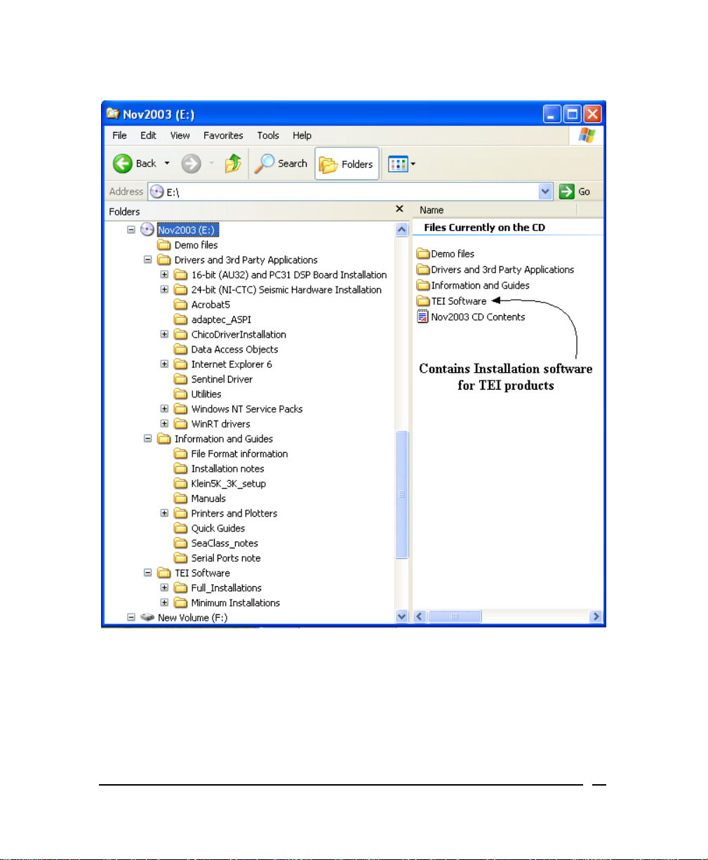
FIGURE 1. Typical listing of TEI software installation folders
TEI software is compatible with Windows NT 4.0, Windows 2000, and Windows
XP. The following notes will help you achieve a smooth installation of the
software.
June 2004 BathyPro User’s Manual 10
Page 11

• Please exit from all other applications before running any of the installation
programs.
• You will not be able to complete the installation on an NT4.0 or
Windows 2000 system if you do not have administrator’s rights. All Isis
“black boxes” ship with a user name Isis. In this case the Isis user name
has administrator’s rights and does not require a password.
• Each application is installed by browsing to the appropriate folder (for
example, Isis6.10 Install) on the CD and double-clicking on the
SETUP.EXE file found in that folder.
• TEI recommends that if you have more than one hard drive, you install the
software on the second (usually the D:) drive, using the default folder names
on the CD. You will be given the option to select any drive during the setup
process, select the Custom option and change the drive letter.
• The first installation on an NT4.0 system requires a reboot during the
installation; however, this only occurs for the first installation. Under
Windows 2000, no rebooting is necessary
However, you
must reboot the system after installing under
during the installation process.
Windows NT 4.0.
• For each application, a number of sample data files can be optionally
installed. These files will reside in a subfolder called Demo Files within each
application’s main folder. These special files can be played back or
processed by the relevant TEI applications without a TEI sentinel being
installed. If no sentinel is attached, a message displays, indicating either
that a sentinel was not found or that the sentinel is damaged. However, you
can still play back the sample files that come from the CD.
• In order to run the software in acquisition mode, or to play back or process
other files, you will need a TEI sentinel attached to the LPT1 printer port.
Contact TEI if you need a sentinel.
• If the operating system is Windows NT 4.0 or Windows 2000, you will need
to install a sentinel driver. The driver is included on the CD in the Sentinel
folder; a text file, with installation instructions, is in that folder.
• In the case of Windows NT 4.0, Service Pack 5 (or higher) needs to be
installed. Service Pack 5 is on the CD.
• The TEI manuals that are installed with the software are in Adobe Acrobat
PDF format. Acrobat Reader software (required to read the PDF files) is
also on the CD.
• The CD has a number of other folders containing drivers and applications
that could be required; each folder has a text file with more information.
June 2004 BathyPro User’s Manual 11
Page 12

• To remove the software, use the Add/Remove Programs utility in the
Windows Control Panel collection of utilities.
• The installations make two changes which are not restored when the
programs are removed using Add/Remove Programs. They are:
• the addition of a folder called [TEIdlls] in the Windows or WINNT folder, and
• a modification to the PATH environment variable which adds the [TEIdlls]
folder to the PATH. The [TEIdlls] folder can be safely deleted after all TEI
software has been removed.
Solutions to Some Common Problems
Problem: After about five minutes the installation does not complete and
the Windows desktop does not return.
Solution: Try again after using Ctrl + Alt + Delete to shut the system down
and restart. The problem can be caused by applications running
in the background or not being shut down before running the
installation.
Problem: Under NT/98 the installation may fail after the first re-boot, with a
message that it cannot locate the file SETUP.EXE.
Solution: This can occur if the CD ROM drive is slow getting started after
the first reboot. Just use Explorer to double click on setup.exe
again, and the installation will proceed normally.
Problem: There is insufficient space on the C: drive, even though D: (or
another) drive has been chosen to install the programs.
Solution: Under Windows NT, the Windows Installer needs to build the
complete Installer Engine and files on the C: drive. The file can
be as large as 250 MB for a full installation. Windows 2000 will
require much less space, since the operating system includes
the Installer Engine.
Problem: After the Installation completes, you see the message, “The
dynamic link library map.dll could not be found in the specified
path…” when the program is started.
Solution: You MUST reboot the system after finishing the installation. This
is necessary so that changes to PATH environment variable can
be applied.
June 2004 BathyPro User’s Manual 12
Page 13

Problem: When you try to connect to a serial port in DelphSeismic or
DelphMap, you may receive this message: “Serialdll.dll was
previously loaded from an unexpected location…” This will only
occur on a system that has had a previous version of either
DelphMap or DelphSeismic installed.
Solution: First close the serial server (if it’s running), then search for the
following files: SERIALDLL.INI and SERIALSRV.INI (These are
found in the Windows folder.) When you find these files, delete
them.
Problem: You may not be able to install all the options (demo files,
manuals, help files) unless you can free enough space on the C:
drive.
Solution: Consider using the Minimum Installations option located on the
CD to install only the programs you need.
Problem: When first running Isis after installing a new version, you receive
an error message that says your Isis CFG configuration file is out
of date.
Solution: This message alerts you that CFG files created with versions of
Isis earlier than this version of Isis are incompatible. Click OK to
accept the message. A new, compatible CFG file will be created
during your current Isis session. In future Isis sessions, the
incompatibility message will no longer appear.
Problem: You receive error messages such as The procedure entry
point xxxxxxxxx could not be located in the dynamic link
library yyyyyy.dll when trying to start one of the TEI
applications.
Solution: This error may occur on a system which has had earlier versions
(prior to Fall 2000) of TEI software installed. Use Windows
Explorer to search for the following files:
About.dll HydroNavCurve.dll mpx_mape.dl ShpLib.dll
ASRVAPI.dll HydroNavInfos.dll Navpntw.dll SinglePrc.dll
Attitool.dll HydroNavPlan.dll Navprcw.dll SpeckleFilter.dll
AuxDlfDll.dll HydroTools.dll Navtools.dll Speed.dll
Bathtool.dll ImpObj.dll ObjectDll.dll TEISplash.dll
June 2004 BathyPro User’s Manual 13
Page 14
Chrutlw.dll Importxt.dll ObjectToBdd.dll TeiGUIExt.dll
CMGBase.dll LinearFeature.dll Palette.dll TEImpxmap.dll
D24Param.dll lxtools.dll patchtst.dll Tide.dll
DdsErr.dll TEImap.dll PIPETRK.DLL TimeTag.dll
dxflib.dll mifutil.dll PitchYaw.dll TVGAuto.dll
Encode.dll MOSAIC.DLL Printer.dll VecPropDll.dll
EncodeS.dll Mpx_Country.dll profile.dll Vif2xyz.dll
Geometry.dll Mpx_line.dll qtclib.dll Volume.dll
geotiff.dll Mpx_main.dll SeisDemo.dll XtfTools.dll
HydroNavAtti.dll mpx_map.dll Serialdll.dll
These files
must be unique on the system (that is, there must be only one
instance throughout your entire computer). The installer copies the latest version
to a folder {Windows Folder}\TEIdlls during the installation process. If any files
with the above names are found that are not in {Windows Folder}\TEIdlls, then
you should delete (or rename) them.
With the Summer 2001 release of TEI software, some DLL
names changed to avoid conflicts with other non-TEI
applications. The DLLs that conflicted were:
map.dll and
splash.dll. If you are upgrading from the Fall 2000 release of
TEI software, delete map.dll and splash.dll from c:\{Windows
Folder}\TEIdlls.
Note:
{Windows Folder} is the folder on your system where the Windows
operating system is installed. For example, C:\WINNT, C:\Windows or C:\Win9x
are {Windows Folder} types.
Problem: There is no display of the timing parameters in the DelphSeismic
Recording Parameter Settings dialog box, and there is no display
June 2004 BathyPro User’s Manual 14
Page 15

of either the signal window or the pipe display in the Isis
pipetracking module.
Solution: This problem can occur with certain “high-end” hardware
accelerated graphics cards such as ATI Rage Pro, and Voodoo
3d Fx. Right-click on the Windows Desktop, select Properties →
Settings → Advanced → Troubleshooting (or Properties →
Settings → Advanced → Performance), and reduce the
amount of hardware acceleration that is being used.
Problem: You receive an error message during installation of TEI software.
For example, you may see this message:
Error — Unable to write to temporary location
Solution: You may see that message if you are running Norton (or other
brands, too) anti-virus software. Check to see that you have
disabled your anti-virus software. The solution is to
turn off Norton Auto-Protect:
1. Right-click the Norton icon (or other anti-virus icon) on the
Windows taskbar.
2. Select Disable Auto-Protect when prompted.
3. Resume installing your TEI software.
4. When the installation completes, re-boot your PC.
When the system restarts, Norton Auto-Protect will be reenabled by default.
temporarily
Program-Specific Problems and Solutions
Some problems are limited to one application or another. For application-specific
problems, please see the Triton Elics International user’s manual relevant to your
situation.
Getting started with BathyPro involves knowing the input and output of BathyPro,
which programs are appropriate for processing data, what your system
environment’s minimum requirements are, and how to install the program.
June 2004 BathyPro User’s Manual 15
Page 16

What BathyPro Does
The purpose of BathyPro is to process, either interactively or in batch mode,
single beam and multibeam data, resulting in output of DDS_VIF or DXF files that
can be imported into DelphMap®.
In the course of using BathyPro to produce your DDS_VIF files or DXF files you
can:
• process and smooth navigation
• remove “spikes” or “glitches” from the motion sensor data
• process and edit the bathymetry data from multibeam, interferometric or
single beam sensors
• build a digital terrain model (DTM)
• extract depth contours
• extract XYZ data to go into an ASCII file
Your Data Type Determines Your Processing Path
The type of BathyPro data you intend to process — single-beam or multibeam —
determines which of four programs (bathypro.exe, bathedit.exe, attedit.exe, or
sbeamedit.exe) you use to get your DDS_VIF or DXF output files. Among these
programs, only bathypro.exe can be used for both data types.
The Paths for Processing Multibeam Data
Multibeam data can be processed in automatic (batch) mode or in
interactive mode.
In the automatic (batch) mode, or path, of processing multibeam data,
BathyPro uses a suite of modules within the larger BathyPro application.
Each module within the BathyPro application performs processing specific
to multibeam data. Chapter 2 through Chapter 4 explain how to use
BathyPro in automatic mode to process multibeam data this way.
In the interactive mode, or path, of processing multibeam data, you use two
programs (instead of the BathyPro executable) in this order:
• Bathy Edit --- editing of individual bathymetry pings using BATHEDIT.EXE.
• Attitude Edit --- editing of motion sensor data using ATTEDIT.EXE
Chapter 2 through Chapter 4 explain how to use BathyPro in interactive
mode to process multibeam data this way.
June 2004 BathyPro User’s Manual 16
Page 17

The Paths for Processing Single-Beam Data
Single-beam data also can be processed in automatic (batch) mode or in
interactive mode.
In the automatic (batch) mode, or path, of processing single-beam data,
bathypro.exe again is the program to use. Each module within the larger
BathyPro application performs processing specific to single-beam data.
Chapter 6 explains how to use BathyPro in automatic mode to process
single-beam data this way.
In the interactive mode, or path, of processing single-beam data, you use a
program called sbeam.exe, instead of processing your data with the
bathypro.exe program. Chapter 6 explains how to use BathyPro in
interactive mode to process single-beam data this way.
Data Input for Either Type of Processing
The data input to BathyPro can be in a number of different formats:
• Raw data — stored in XTF format
• Pre-computed X, Y, Z data — stored in ASCII text files
• Grid data — in the form of a DDS_VIF file
For any BathyPro project (DTM file), the file list can only contain one of
these types. Consequently, you cannot mix XYZ, XTF, and DDS_VIF files
(data sets) in the same project.
For each type of file the BathyPro menu will be different:
• When importing an ASCII file, navigation, attitude, bathymetry editing and
speed velocity correction are not available.
• When importing a grid file, the BathyPro menu will propose a set of filtering
algorithms and contour extraction values.
Data Output for Either Type of Processing
The output of BathyPro can be three types of files:
• Raster graphic files containing the DTM (DDS_VIF)
• Vector graphic files containing the contour data (DXF)
• XYZ ASCII files also are exportable.
The first two file types can be imported directly into DelphMap.
June 2004 BathyPro User’s Manual 17
Page 18

The DTM model is a grid of square cells. A unique depth value is assigned
to each cell. This value is computed from all the beams falling in that cell
according to the user’s choices: average, max, min, last, first, or from the
most vertical beam. The geographical position of a cell is the center of the
cell.
What BathyPro Needs from You
You must have the following to use BathyPro:
• a monitor driven by a video card capable of displaying 16 million colors
• an Intel Pentium® CPU running Windows NT, Windows 2000 or Windows
XP
• 32 megabytes of RAM
• at least 10 megabytes of free disk space
• an appropriately configured software dongle from Triton Elics International
Installing the BathyPro Software
Bathy Pro comes to you on a CD-ROM. You use the setup utility from the
CD-ROM to install the program. (Do not merely copy the CD-ROM’s contents to
your hard disk.)
To install BathyPro
1. Put the CD-ROM into your computer’s CD-ROM drive.
2. Browse for the installation or setup program on the CD-ROM that runs the
installer; click on the installation program name or press [Enter].
The setup/installation utility runs.
3. Follow the instructions in the install program.
The setup/installation utility will inform you when installation is complete.
June 2004 BathyPro User’s Manual 18
Page 19

Chapter 2: Working with Attitude Editor
BathyPro comes with a stand-alone utility called Attitude Editor. Attitude Editor is
one of two such utilities that can be used to interactively clean multibeam data in
an XTF file. (The other utility is Bathy Editor, the subject of Chapter 3.)
Attitude Editor gives you control over the following:
• setting the maximum difference for roll, pitch, heave as criteria for flagging.
• showing data from a given line, if flagged, to reveal roll, pitch, and heave
with data in “before and after” flagged points to help you find any bad points.
Using the aforementioned controls, you can do any of the following:
• flag a bad data point
• keep the data and continue looking for other errors, or
• flag all, which instructs Attitude Edit to process all data based on criteria you
have already set.
• change criteria settings during processing, if needed.
Using the Dialog Boxes in Attitude Editor
Like Bathymetry Editor, Attitude Editor has two dialog boxes for you to interact
with. You use the first one, called the Attitude Editor dialog box, to set up your
parameters. You use the second one, called the Processing attitude… dialog
box, to do the processing based on the parameters you specified in the first
dialog box.
To run Attitude Edit
• Double-click the program named ATTEDIT.EXE (Attitude Editor) or its icon.
Your display resembles the example shown in Figure 2.
June 2004 BathyPro User’s Manual
19
Page 20
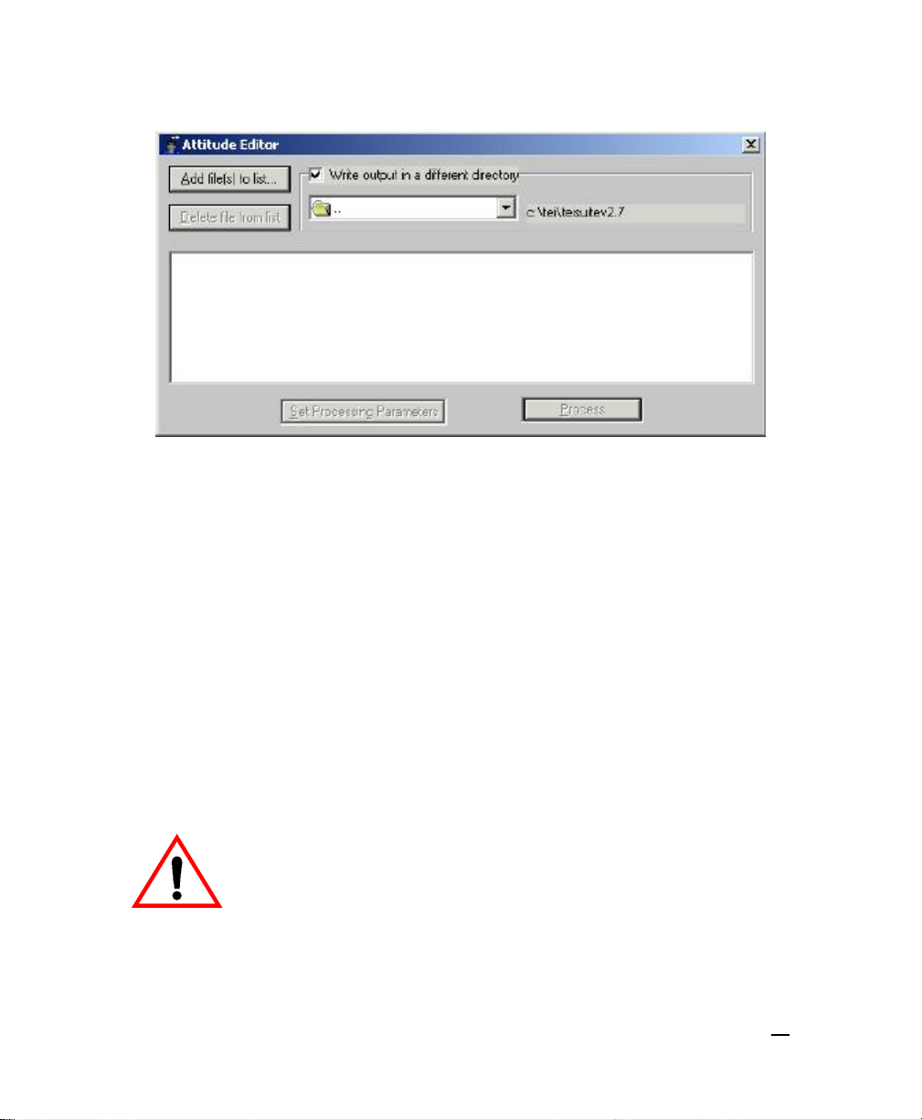
Figure 2. Typical preliminary Attitude Editor dialog box
Setting Parameters in the Attitude Editor Dialog Box
After the Attitude Editor program is running, you can set up your parameters for
processing.
To set your parameters in the Attitude Editor dialog box
1. Click Add file(s) to list… and select one or more files having the file
extension XTF. The XTF file(s) must be composed of multibeam data. All
files in the list will be processed. Choose Delete file from list if a specific
line is not desired.
2. Put a check mark in Write output in a different directory and click the
down arrow to browse for the directory you want.
The system adds the specified XTF file name to the initially blank area.
June 2004 BathyPro User’s Manual
Do not have your working directory be the same as the directory
holding your original XTF file(s). In the course of processing, any
file modifications will be written back to an XTF file of the same
name that you specified from the Add file(s) to list… button. If
the target XTF file is your original XTF file, it will be overwritten.
Make sure, therefore, that the directories for the named XTF
file(s) differ.
20
Page 21
3. In the manner of steps 1 and 2, continue to add XTF files until your list is
complete. The Set Processing Parameters button becomes ungrayed as
soon as you have specified a file for Attitude Editor to work on.
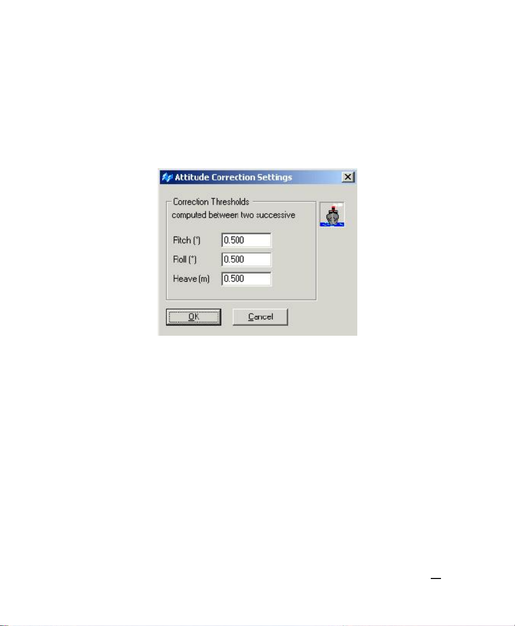
4. After you are through adding files, click Set Processing Parameters.
The system displays the Attitude Corrections Settings dialog box (Figure
3).
Figure 3. Attitude Corrections Settings dialog box
5. The threshold values refer to the largest change in Pitch, Roll, and Heave
between successive updates. In order to make useful entries here, the
user needs to know something about the conditions that existed at the
time the data were acquired. Factors such as a small vessel operating in
rough weather, or a motion sensor with a slow update rate, might cause
the default values to be too small. You only want to remove spikes or
glitches in the data due to transmission faults from the sensor.
Consequently, you want to set the threshold values high enough to reject
the small anomalies of movement, but also set the values low enough to
catch the large anomalies. In the majority of cases the default values will
be correct.
6. Click Process.
The system displays the Processing attitude… dialog box (Figure 4).
Processing starts immediately. It will run to completion unless you click
Pause or Stop.
June 2004 BathyPro User’s Manual
21
Page 22
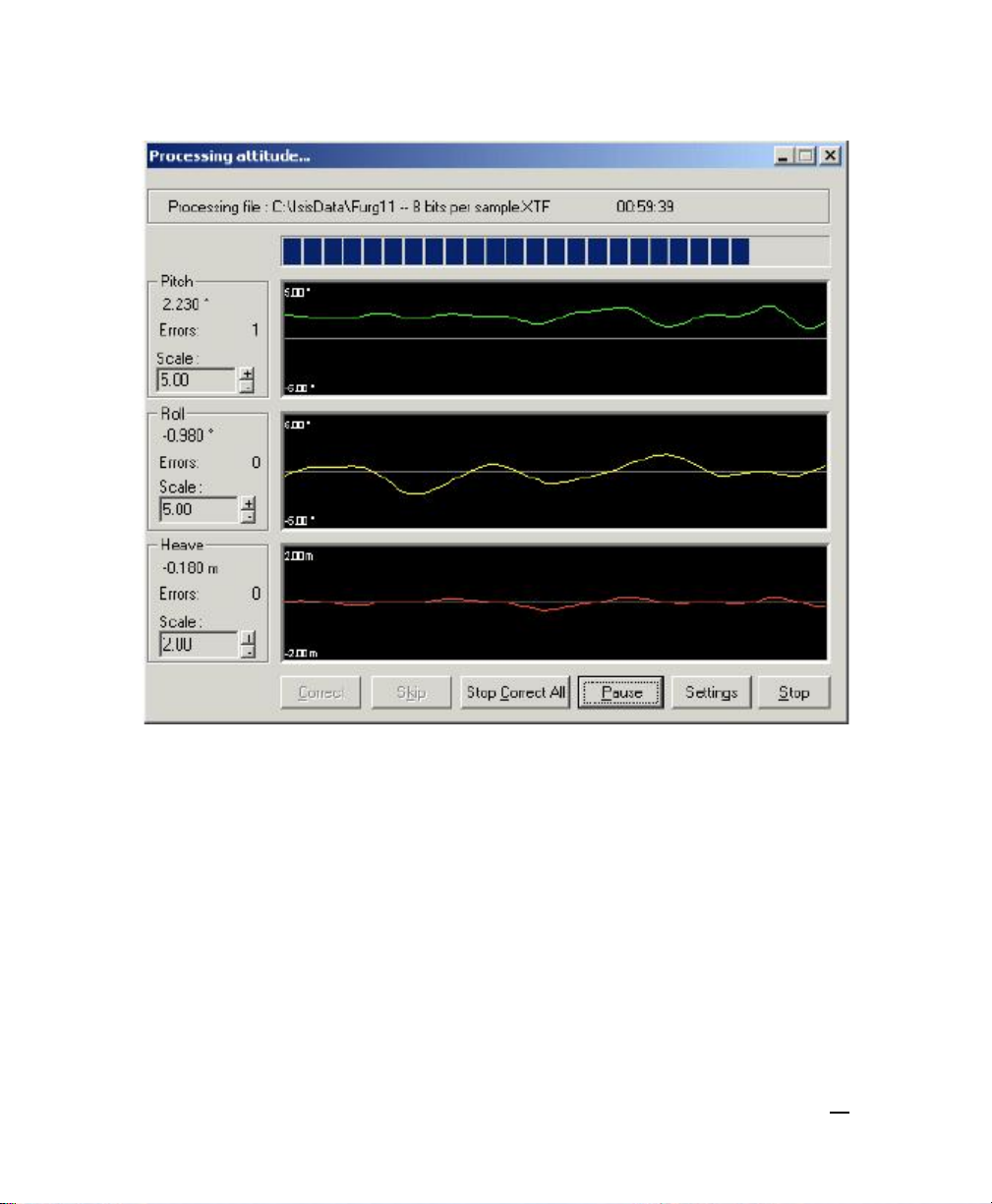
Figure 4. Initial Processing Attitude dialog box
Interpreting the Processing Attitude Display
In the Processing Attitude dialog box (Figure 4), all attitude data displays in the
three sections. As the figure shows, the top line of the dialog box shows the path
and file name of the XTF file being processed; to the right of the file name is the
elapsed processing time. Below that are separate displays for Pitch, Roll, and
Heave aspects of your XTF data, with controls for increasing or decreasing the
scale of those aspects. The straight, white lines running through the middle of
each type of attitude (pitch, roll, and heave) are reference points representing the
“zero aspect” of each parameter (that is, no pitch, roll, or heave present). At the
June 2004 BathyPro User’s Manual
22
Page 23

bottom of the screen there is an action area of buttons for making any attitude
corrections you may feel are necessary.
To enhance or suppress a parameter’s line
If you want to enhance or suppress the visual representation of the attitude
parameters, click on the plus or minus buttons. Units are in degrees or meters.
The greater the scale numbers, the flatter the representation; the fewer the scale
numbers, the more detail (more undulations) you see in the displayed lines for
pitch, roll, and heave.
To see how the program has labeled a given ping
In the Processing attitude dialog box, put your cursor on the white point in order
to see the Pitch, Roll, and Heave values Attitude Editor reports for this section of
your data.
Making Corrections Using Processing Attitude Display
If a solid white circle or square appears in any of the displayed areas during
processing, the program is telling you that some value you specified in the initial
Attitude Editor dialog box has been exceeded. You can then choose to Correct
it, Correct All, or Continue, or re-specify values in Settings, based on your
assessment of the data.
To accept or reject a displayed value
If attitude activity in the display stops, it indicates that specific criteria has failed.
Choose options to Correct, Skip, or Correct All.
You have these options:
• To have the program flag the ping and thereby keep it from being included
in the processing, click Correct. The corrected ping will have the mean
value of the points immediately preceding and following the rejected point.
or
• To have the program accept the ping for processing, click Skip.
or
• If you want all pings to be accepted or rejected according to the parameters
you specified in the Attitude Corrections Settings dialog box (Figure 3), click
Correct All and the program will run to completion.
June 2004 BathyPro User’s Manual
23
Page 24

• If you click the Pause button, processing pauses, the button now says
Continue, and activity in the display is suspended until you click Continue.
• If you click Settings, Attitude Editor recalls the Attitude Correction Settings
dialog box for your inspection, where you can make adjustments to Pitch,
Roll, and Heave, if desired, to fine-tune the process.
When the program completes, the Processing attitude… dialog box
disappears Attitude Editor dialog box reappears. There is no additional
indicator of processing completed.
• To exit the program, click the Exit control button (the x in the upper right
corner of the Attitude Editor dialog box).
After you have finished processing your XTF file with Attitude Editor, you
can go to Bathymetry Editor or BathyPro to finish processing data.
June 2004 BathyPro User’s Manual
24
Page 25

Chapter 3: Working with Bathymetry Editor
BathyPro comes with a stand-alone utility called Bathy Editor. Bathy Editor is one
of two such utilities that can be used to interactively clean multibeam data in an
XTF file. (The other utility is Attitude Editor, the subject of Chapter 2.)
Bathymetry Editor (BATHEDIT.EXE) is used to detect and suppress bad beams
in raw XTF data files. Bathymetry Editor will produce and output a new XTF file
with beams that you have flagged as BAD. These beams will be ignored when
producing a DDS_VIF file for display in DelphMap.
You can add as many XTF files as you wish with the ADD button. You must then
select an output directory name where the processed files will be stored. This
working directory must not be the same as the directory containing the input file.
Bathymetry Editor will never overwrite existing XTF files.
Using Bathymetry Editor’s Two Dialog Boxes
Bathymetry Editor has two dialog boxes for you to interact with. You use the first
one, called the Bathymetry Editor dialog box, to set up your parameters. You
use the second one, called the Processing Bathy… dialog box, to do the
processing based on the parameters you specified in the first dialog box.
To run Bathymetry Editor
The program loads. Your display resembles Figure 5.
June 2004 BathyPro User’s Manual
25
Page 26
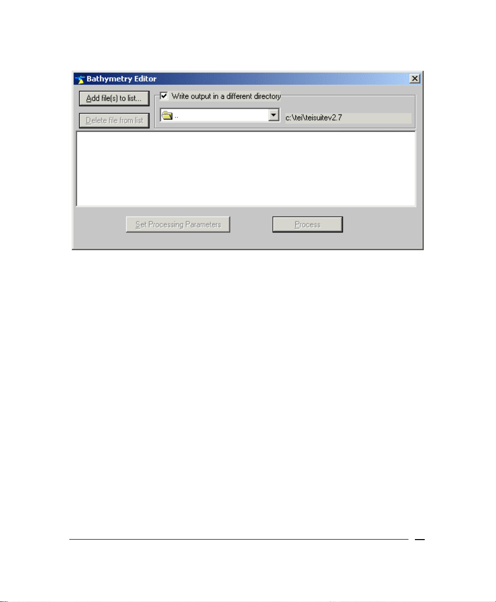
Figure 5. Typical initial Bathymetry Editor dialog box
Setting Bathymetry Editor’s Parameters
After the Bathymetry Editor program is running, you can set up your parameters.
To set your parameters in the Bathymetry Editor dialog box
1. Click Add file(s) to list… and select one or more files having the file
extension XTF. All files in the list will be processed. Choose Delete file
from list if a specific line is not desired.
Before you specify files to add to the list, the functions Delete file from
list, Set Processing Parameters, and Process buttons are grayed out.
They remain unavailable until a file or files are added to this dialog box.
2. Put a check mark in Write output in a different directory and click the
down arrow (↓) to browse for the directory you want.
June 2004 BathyPro User’s Manual
26
Page 27
Do not have your working directory be the same as the directory
holding your original XTF file(s). In the course of processing, any
file modifications will be written back to an XTF file of the same
name that you specified from the Add file(s) to list… button. If
the target XTF file is your original XTF file, it will be overwritten.
Make sure, therefore, that the directories for the named XTF
file(s) differ.
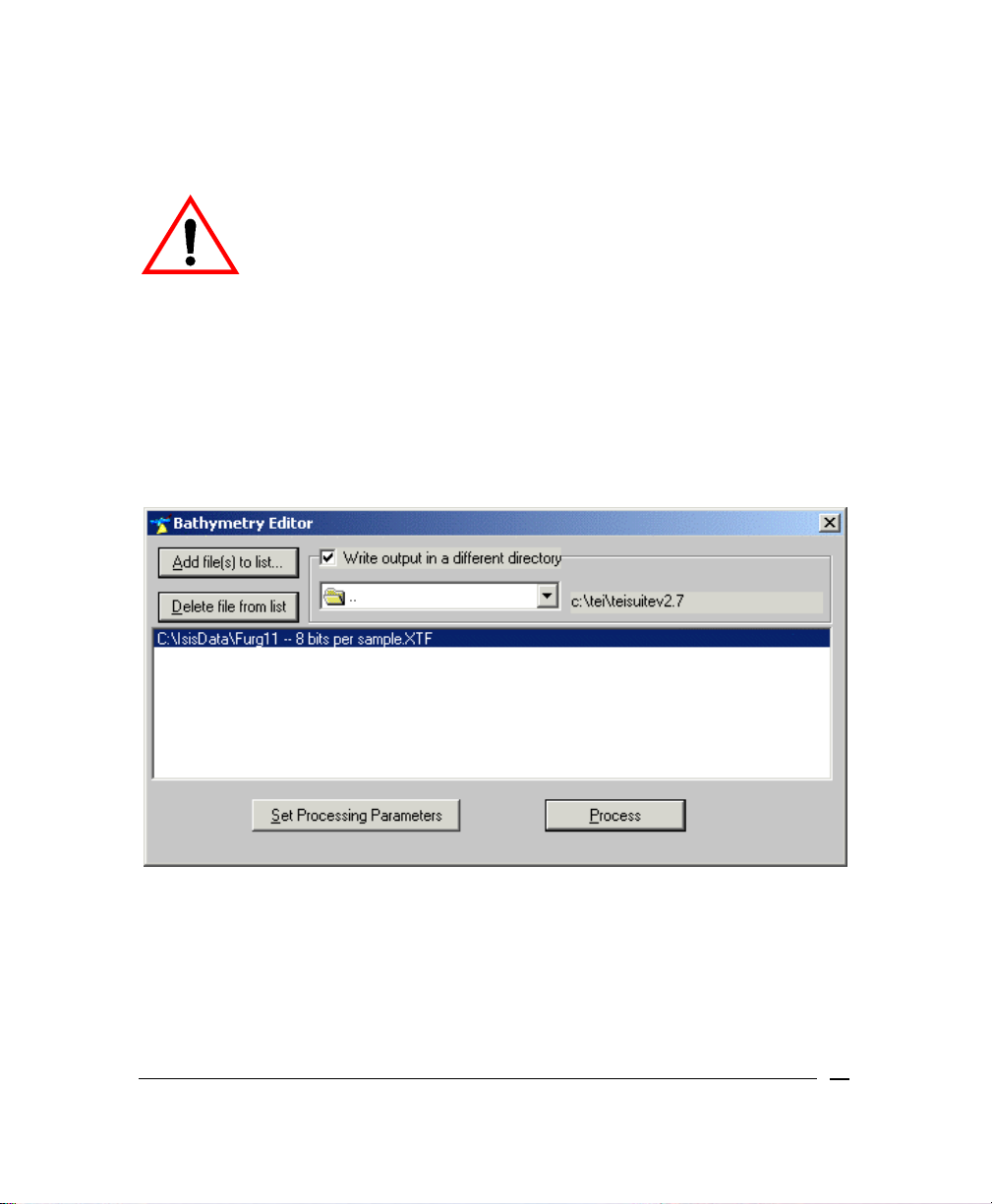
After you have specified your file or files, the Set Processing Parameters and
Process buttons become available. Figure 6 shows an example of this.
Figure 6. Bathymetry Editor main dialog box with file added
3. Click Set Processing Parameters to see the Bathymetry Correction
Settings dialog box, where you can inspect beam characteristics and, if
desired, change them.
June 2004 BathyPro User’s Manual
27
Page 28
When you click Set Processing Parameters, the system displays the
Bathymetry Correction Settings dialog box. Figure 7 shows an example of
this dialog box.
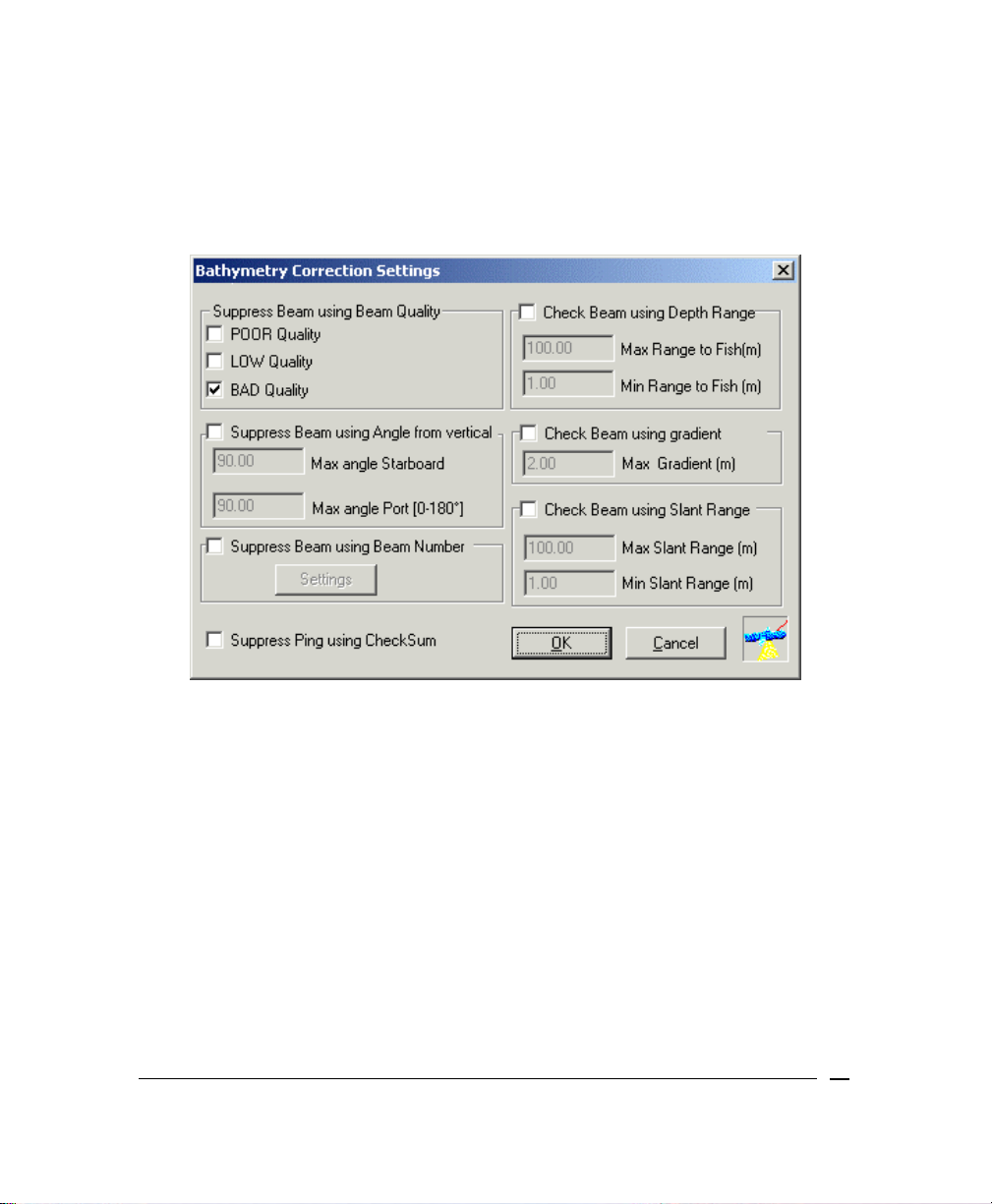
Figure 7. Bathymetry Correction Settings dialog box
In the Bathymetry Correction Settings dialog box:
• Suppress Beam using Beam Quality — All beams flagged as bad quality
by the sonar will be ignored by BathyPro. In addition, you can choose to
ignore (suppress) beams flagged as POOR Quality, LOW Quality, or BAD
Quality by putting a check mark in the boxes next to these parameters. (If
you leave a box unchecked, you are choosing not to suppress these
marginal quality beams, so they will be included with your BathyPro
processed data.)
• Suppress Beam using Angle from vertical — Put a check mark next to
this parameter if you want to specify which beams, based on their angles
June 2004 BathyPro User’s Manual
28
Page 29
from the vertical, will be omitted from processing. Note that this implies that
the beams are being corrected using the motion sensor.
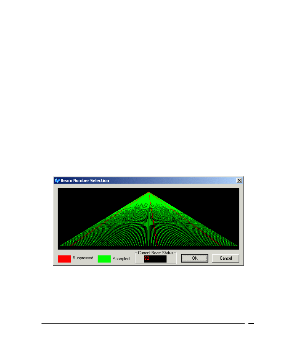
• Suppress Beam using Beam Number — This simply is a way of ignoring
any beam that is known to be generating erroneous data. After putting a
check mark next to the parameter to enable it, click Settings to display the
Beam Number Selection dialog box (Figure 8) where you can select
individual beams to be ignored.
• Check Beam using Depth Range (m) — Enter the maximum and minimum
depths, in meters, that are expected in the survey area. BathyPro will ignore
any depths exceeding these values. Note that this is the depth below the
transducer and does not include any Z offset.
• Check Beam using Gradient (m) — If this choice is enabled, the program
looks at the eight depth cells immediately surrounding each depth value and
rejects the point if it differs by more than the specified gradient value (in
meters) from the mean of these eight values. The gradient default is two
meters.
• Check Beam using Slant Range — This process selects the maximum
and minimum slant range that will be accepted by BathyPro.
Figure 8. Beam Number Selection — three beams suppressed
After you have set up the various parameters in the Bathymetry Editor dialog box
(Figure 6) that you wish to apply to the data, click Process. The Bathymetry
Editor dialog box disappears and the system displays the Processing Bathy
dialog box. At this point the program runs to completion unless you click Pause
June 2004 BathyPro User’s Manual
29
Page 30
or Stop. Figure 9 shows an example of Bathymetry Editor in the middle of
processing a file.
June 2004 BathyPro User’s Manual
30
Page 31

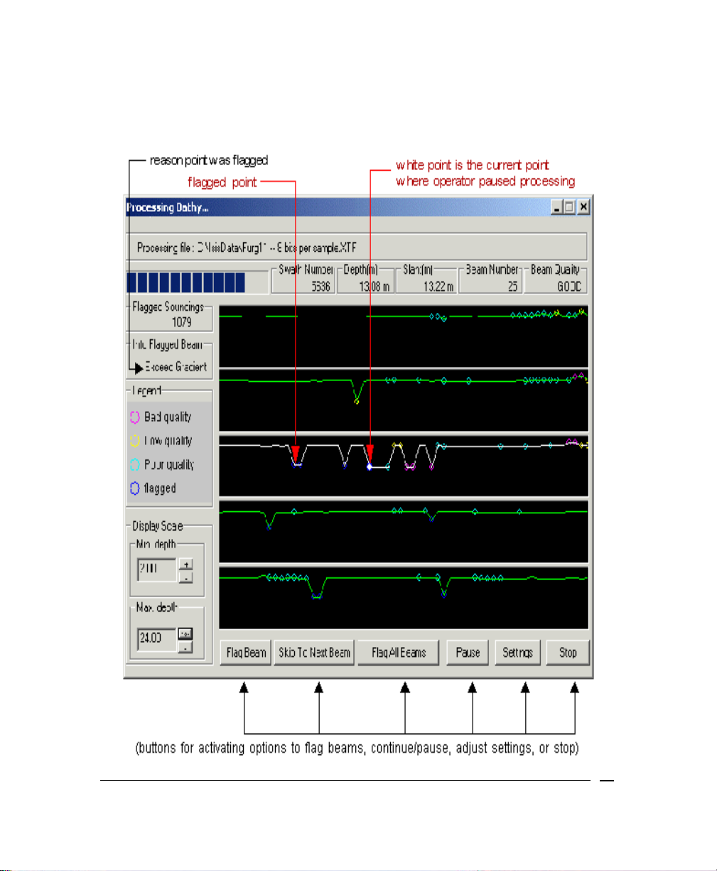
Figure 9. Typical display of nearly processed bathymetry data
Interpreting Displayed Processing of Bathy Data
Processing of your XTF file is initiated from the Processing Bathy… dialog box
(Figure 9). Reading from top to bottom in that dialog box, there is a status area, a
flagged soundings area, an info flagged beam area, a legend area, a display
area, and an action (buttons) area.
Status Area
Topmost in this part of the display is the name of the processed file and its
path. Beneath that are five rectangles, which are also part of the status
area. The leftmost rectangle in the status area is reserved for the Progress
Bar. Initially it is blank as shown in Figure 9. During processing, for each file
(line) being processed, the progress bar increases in length indicating the
amount of line remaining to process.
To the right of the progress bar are some status boxes: Swath Number,
Depth, Slant, Beam Number, and Beam Quality. When you move your
trackball or mouse pointer in different parts of the Display area, the
information in these four boxes changes according to your pointer’s position
in the data.
Flagged Soundings
This box displays the total number of soundings that have been flagged as
bad in the current session.
Info Flagged Beam
This box states why the current beam has been flagged. Examples:
• Exceed Diff
• Exceed Range
• Poor or Low Quality
• Exceed Gradient
June 2004 BathyPro User’s Manual
31
Page 32

Legend Area
This area is located to the left of the display area and shows the notation
used to represent the qualitative value (Bad quality, Low quality, Poor
quality, or flagged) of points in your data.
• Bad quality points, displayed in magenta, are points that will be eliminated
from the final, processed XTF file.
• Low quality points, displayed in yellow, may appear if you had checked the
LOW Quality check box in the Bathymetry Correction Settings dialog box
Figure 7).
(
• Poor quality points, displayed in cyan, may show up in the Processing
Bathy… dialog box if you had checked the POOR Quality check box in the
Bathymetry Editor dialog box.
Display Scale
Appearing in the lower left corner of the Processing Bathy… dialog box, this
panel shows two optional controls: Min. depth and Max. depth. By clicking
on the plus or minus buttons, you can exaggerate or minimize the beam
representations appearing in the display area (see ‘
for the five swaths. Units are in meters.
Display Area’) reserved
Display Area
This is an area of five horizontally banded boxes. Each of these boxes is
reserved for an individual line or swath. The Bathymetry Editor program can
symbolically display lines and points in your data in this part of the dialog
box. The left portion of the line indicates beam #1. During processing, all
beams will be displayed across the line in the box.
Action Area
Aligned along the bottom of the Processing Bathy… window are six action
buttons: Flag Beam, Skip To Next Beam, Flag All Beams, Pause,
Settings, and Stop. They are used for managing the beam points
appearing in the data. ‘
June 2004 BathyPro User’s Manual
Deciding What to Process’ (described next).
32
Page 33

Deciding What to Process
If a solid white circle or square appears in any of the five displayed swaths during
processing, the program is telling you that some value you specified in the initial
Bathymetry Editor dialog box has been exceeded. You can then choose to Flag
Beam, Skip To Next Beam, or Flag All Beams, based on your assessment of
the data.
To see how the program has labeled a given point
Put your cursor on the colored dot or circle on the line to see how Bathymetry
Editor describes the beam quality (upper right of status bar).
Note: When a solid white dot appears, the operator has an option to classify it.
See the options in ‘
To accept or reject a displayed point
• If the program labeled a data point beam quality as good, and the point also
looks acceptable to you, but the program flagged the point for some reason
(perhaps due to low co-linearity, exceeding max depth, etc.), click Skip To
Next Beam to keep the point.
• If a data point is an obvious spike, you should reject it for processing; select
Flag Beam to reject it. If you wish to examine all points flagged by the
program, continue using this technique of flagging and finding points until all
processing completes.
• If you feel confident that all points specified by the parameters you set up in
the first dialog box (Bathymetry Editor, Figure 6), go ahead and click Flag
All Beams. The Bathymetry Editor program will then process the entire XTF
file according to your earlier specifications.
• If the display stops, it indicates that a specific criterion in the Info Flagged
Beam has failed. Choose options to Flag Beam, Skip to Next Beam, or
Flag All Beams. To stop the display, click Pause; to continue, click
Continue. To reset the initial settings, click Settings.
• Continue through data set until the file is completed.
• To exit the program, click the Exit control button (the x in the upper right
corner of the Bathymetry Editor dialog box).
After you have finished processing your XTF file with Bathymetry Editor, you are
ready to use Attitude Editor to continue processing the file in additional ways.
Attitude Editor’s functionality and use is addressed in the chapter entitled,
Working with Attitude Editor’.
‘
To accept or reject a displayed point’.
June 2004 BathyPro User’s Manual
33
Page 34

Chapter 4: Making a DTM with BathyPro
What BathyPro Does
The purpose of BathyPro is to process single-beam and multibeam data,
resulting in an output of DDS_VIF files or DXF files that can be imported into
DelphMap as a digital terrain model (DTM).
In the course of using BathyPro to produce your DDS_VIF files or DXF files you
can:
• process and smooth navigation
• remove “spikes” or “glitches” from the motion sensor data
• process and edit the bathymetry data from multibeam, interferometric or
single beam sensors
• build a digital terrain model (DTM)
• extract depth contours
• generate a soundings chart in DXF format
• extract XYZ data to go into an ASCII file
• calculate volume differences between two DDS_VIF files
• Patch Test. BathyPro also contains a patch test utility (Chapter 7, ‘Running
a Patch Test’) having its own set of internal functions. With patch test you
can:
• automatically calculate pitch, roll, yaw, latency and velocity parameters;
• display 2-D color-coded data, which can be corrected with offsets that act
as a confidence check with computed corrections;
• respond to operator-supplied coarse and fine adjustments as small as 0.01
and 1 millisecond;
• show each iteration of the patch test process using a least-squares
computation
To run BathyPro and provide files to the program to use
1. Double-click the program named BATHYPRO.EXE or its icon.
Your initial BathyPro Editor display resembles the screen shown in Figure
10:
June 2004 BathyPro User’s Manual
34
Page 35

Figure 10. Initial BathyPro Display
The order of processing follows the order of the main menu items as they are laid
out from left to right in the application window (
Project, then Project Settings,
Bathy Processing, Volume, Patch test, Windows, and Version).
2. Each time you launch a BathyPro project, the settings (including file
names, processing parameters, sensor geometry and projection settings)
can be saved. To restore a project, Open an existing project. If you are
beginning from scratch, or would like to create a new project, then choose
Project → New.
3. Right-click anywhere in the Project files window.
The system displays a list of file types from which you can choose (Figure
11).
4. Choose one of the file types to add one to your DTM window.
June 2004 BathyPro User’s Manual
35
Page 36

Figure 11. List of available file types to add in Project Files
The kind of processing available will be determined by the type of file you choose
here. Table 1 defines the capability and applicability of each file type with respect
to BathyPro.
TABLE 1. Imported file types and their uses in BathyPro
File Type Description and Kind of Processing Possible
Add XTF files
(Multibeam)
Add XTF files
(Interferometric
data)
Add XTF files
(Single Beam Data)
June 2004 BathyPro User’s Manual
processing of standard XTF multibeam data (for
example, 8101, 9001, Simrad 2000)
processing of data from the Klein 5400 mutibeam
sidescan sonar.
processing single beam Echosounder data recorded via
an RS232 port in an XTF file
36
Page 37

Add XTF files
(Single Beam from
SideScan Data)
Add XTF files
(Auxiliary Channel)
Add ASCII file
(Multibeam Data)
Add ASCII file
(Single Beam Data)
Add XYZ Binary file
(Submetrix,
Simrad, Seabeam)
Add Grid File
processing of bathy data derived from a sidescan sonar
system wherein the total water depth is derived from the
sum of the towfish depth and the towfish altitude
for processing single-beam sounding data stored in any
Aux field of the XTF file
processing of ungridded XYZ Multibeam data in ASCII
format.
processing of ungridded XYZ Single Beam data in ASCII
format
for processing multibeam data stored in other sonar
native formats
processing of DDS_VIF files previously generated in
Bathy Pro
For any of the file types, the system displays a standard Open dialog box where
you can browse for (or type in) your choice.
June 2004 BathyPro User’s Manual
37
Page 38

Figure 12. ASCII file importation setup dialog box, with data
The top half of the dialog box is a look at the first 20 lines of the raw data
collected in your ASCII text file. The bottom right window, an “item #n” window,
serves as a visual reminder of fields you are defining or using to describe the raw
data you will be extracting.
Below the raw data window (and to the left of the “item #n” window) are areas
where you can define new relationships for your data. You do so by working with
three variables:
• Position
• Description
• Unit
Your objective is to map the usable values in your raw data window to those
three variables. In the course of mapping values, you assign descriptions and
units to them.
To see the interaction of mapped positions to variables
If there is more than one “item #n” entry, click on one that is not highlighted to
see the effect in the Position, Description, and Unit boxes.
June 2004 BathyPro User’s Manual
38
Page 39

As you click a different “item #n” entry, the contents of the Position,
Description, and Unit boxes change to match the highlighted item. If there are
no items to click, you will be creating them fresh.
To assign a description
1. In the raw data window, visually identify the first variable you wish to
extract and note how it is delimited.
In Figure 12, for example, the string 07/07/2000 is a date delimited in
three parts: month, day, and year. Each part is delimited by the virgule (/)
character. If the date is a variable to be extracted in this example, then
the first 07 will be item #1 occupying position 01 in the mappable
“item #n” window, the second 07 will be item #2 in position 02, and 2000
will be item #3 in position 03.
2. Do one of the following:
If item #1 exists, click it to highlight it.
The Position, Description, and Unit windows are updated with the
information shown for the item #1 entry.
If item #1 does not exist, type 1 in the Position window.
3. Whether you typed or highlighted the position of interest, now select a
description appropriate for the variable you associated with this position.
You can select one of 14 parameters from the Description combination
box.
To assign a unit and format
1. For the description you assigned, now select an appropriate unit from the
Unit combination box. The combination box has 25 different units/formats.
Your variable now has a complete definition.
2. Click Add/Replace to insert your item in the “item #n” window.
Your variable is now mapped.
To complete the list of items
1. For each variable you are going to extract, continue to map them as items
having a position, description, and unit.
2. Click Add/Replace for each new mapped item you create.
June 2004 BathyPro User’s Manual
39
Page 40

If you choose to skip over a usable variable in your raw data window,
that’s OK — just be sure to account for the skipped variable’s position and
number so that later variables appearing in the raw data window are
mapped to their correct positions.
You can also delete any mapped item using the Delete button.
3. After you have mapped all the variables you wish to extract, click OK.
The program closes the ASCII file importation setup dialog box and
redisplays the BathyPro dialog box with updated information in the Project
files window.
After you choose a file type to add to your project files, the system
displays the Select files to add to the project dialog box. Figure 13
shows the version of this dialog box that is appropriate for XTF files
(multibeam data).
Figure 13. Adding an XTF file to a BathyPro project
June 2004 BathyPro User’s Manual
40
Page 41

Notice the Process All choice in the lower left area of the dialog box in
Figure 13. If all data from the line is to be processed, put a check mark in
the Process All box. (Process All is the default.) If you just want to work
with a portion of an XTF file, and you already know which range of pings
you want to work with, uncheck the box, making the First Scan and Last
Scan boxes ungrayed and accessible. Then you can specify your ping
range.
You won’t get the Process All choice if you are adding ASCII files to the
project. Instead, you’ll get a conventional Windows dialog box for
opening files.
4. After specifying one or more XTF files click Open. Bathy Pro updates its
project files area with the XTF file you specified (Figure 14).
At this point, even though you haven’t processed the data you have
added to your Project files, you could save this BathyPro entity as a DTM
file by choosing
Project → Save As, giving your project a name, and
clicking Save. The file thus saved becomes a mere placeholder for the
processing that will take place later when you are ready to have BathyPro
process your XTF, XYZ in ASCII format, or DDS_VIF Grid files. After that
processing completes, the saved DTM (an ASCII file) contains all the
settings and parameters that are relevant for the files you used in creating
your project. See ‘
Completing Your Project’ for additional discussion of
what it means to save a project.
To expand the list of project files
• Select the name Project files in the Project Files working window and do
one of the following:
• On the numeric keypad, press the asterisk key (*) if you want to expand
everything in the list; or
• Just press the plus key (+) to expand the current level of the list.
When fully expanded, the project files list displays your project files and their
folder locations. Red buttons appear next to the processing stages. Red
symbolizes unstarted or incomplete stages. (As processes complete, the red
buttons will turn green.) An example of a fully expanded list (with nothing
processed) is shown in Figure 14.
To contract a list of expanded project files
• Select Project files in the Project Files working window and do one of the
following:
June 2004 BathyPro User’s Manual
41
Page 42

• On the numeric keypad, press the slash key (/) if you want to contract
everything in the list.
• Select the project name or file name and press the minus key (-) on the
numeric keypad. This will contract just the current level containing the
project name or one of its listed files. The list can’t be contracted with the
minus key if you have selected a processing parameter; you must be at a
higher level to use the minus key.
When fully contracted, only the name Project files appears in the Project
Files working window.
Figure 14. Project files after adding a file and expanding the list
Providing Project Settings to BathyPro
The Project Settings menu has two submenus for you to inspect, where you can
specify Map and Projection settings… and Sensor geometry settings….
To check your projection settings
1. Click Map and Projection settings… to display the Map and Projection
settings dialog box. Figure 15 shows an example.
June 2004 BathyPro User’s Manual
42
Page 43

Figure 15. Typical Map and Projection settings dialog box
The coordinate input for Figure 15 is in Northing and Easting. Data can
also be in geographic coordinates.
June 2004 BathyPro User’s Manual
43
Page 44

This dialog box shows the boundaries of the area, the coordinates of the
northwest corner of the area, and the grid resolution. If necessary, you
can change these parameters to accommodate a larger (or smaller) area
or different northwest corner. The default values will have been detected
from scanning the XTF files.
2. In the Map and Projection settings dialog box you can either change input
or output settings, or you can test the current settings:
a. If you’re going to change the boundaries and/or north-west origin
shown in the dialog box, uncheck the Set Default Limit check box to
make the Boundaries and North-West Origin in Input Projection
Coordinate Units text boxes accessible, then type your values.
The Set Default Limit box initially is checked, making the
Boundaries and North-West Origin text boxes inaccessible.
Uncheck this box if you need to access the text boxes to
change values. (If you recheck the Set Default Limit box
after changing a value, the value returns to the first value
you say when you first displayed the Map settings dialog
box.
b. Inspect the Input Projection area of the dialog box to confirm the
settings shown there are the ones actually used during your data
survey. If the input projection and Datum values match your needs,
click OK. If the displayed values don’t match your needs, click the
Change button next to Input Projection to see the Input Projection
settings dialog box with the subheading “Select Projection” (Figure 17)
accept or change the highlighted projection, then click Next.
c. Set the Grid Resolution you require. In BathyPro, the highest
resolution you can select is 0.01 m; for most bathymetry, resolution
typically would be 0.5 or 1 m. Take in consideration the horizontal
uncertainty of the survey system and not use a grid size smaller then
the resolution of your GPS unit.
d. Optional: Test your latitude and longitude values by clicking Test to
get the Test Projection Settings dialog box (Figure 16).
June 2004 BathyPro User’s Manual
44
Page 45

The system displays the Test Projection Settings dialog box (Figure
16).
e. In the Latitude and Longitude text boxes of the Test Projection
Settings dialog box, specify values based on your survey job.
f. Click Compute.
A trial conversion is performed on the entered latitude and longitude,
and the results in both output and input projections are displayed in
the boxes.
g. Click OK to dismiss the Test Projection Settings dialog box and return
to the Map and Projection settings dialog box.
3. Click OK to close the Map and Projection settings dialog box.
June 2004 BathyPro User’s Manual
45
Page 46

Figure 16. Test Projection Settings dialog box with sample
values
Increasing the resolution increase s your file size dramatically.
For example, increasing resolution in an area from 0.5m x
0.5m to 0.1m x 0.1m will increase the size of the file by a
factor of 25. Be conservative when increasing resolution!
The resolution you select should always be equal to or
June 2004 BathyPro User’s Manual
greater than the resolution of your original data. If you choose
a resolution significantly less than the original data, your
output file will not be displayed correctly in DelphMap.
46
Page 47

Figure 17. Typical Input Projection settings dialog box
h. In the Map and Projection settings dialog box, if you clicked Change
and selected a projection, the system again displays the Input
Projection settings dialog box — this time with the subheading “Select
UTM Zone and Hemisphere” (Figure 18); accept or change the
highlighted zone and click Next.
June 2004 BathyPro User’s Manual
47
Page 48

Figure 18. UTM zone and hemisphere dialog box
The type of dialog box that appears after you choose a projection type will
display settings choices appropriate for the kind of projection you chose. For
example, if you choose Universal Transverse Mercator for your projection type,
you get the dialog box like the one shown in Figure 19, displaying datum choices.
June 2004 BathyPro User’s Manual
48
Page 49

Figure 19. Datum choices after selecting a typical projection
i. Click Finish to accept or change your projection settings.
j. Inspect the Output Projection and, if necessary, makes changes to
the displayed values by clicking on Change next to the Output
Projection. The technique is the same as in the steps for Input
Projection: Select a projection type, any parameters it may require,
then click Finish.
For certain kinds of input or output projections, a special case can exist in the
form of a user-defined datum. That is, if you have a datum that does not fall into
any of the available datum choices listed in the Select Datum dialog box (Figure
19), you can define one for some projections which permit a user-defined datum.
To specify a user-defined datum
June 2004 BathyPro User’s Manual
49
Page 50

1. In the Select Datum dialog box shown in Figure 19, highlight (select)
User-Defined Datum.
The text boxes (right column) shown in Figure 19 become accessible for
modification (Figure 20).
Figure 20. User-Defined Datum fields available to be defined
2. Click Finish in the Select Datum aspect of the Input Projection settings
dialog box.
3. In the available text boxes, specify the values you need that describe your
user-defined datum.
Units for the Ellipsoid parameters shown in Figure 20 are meters (m) for
the Semi-Major Axis, and the inverse of flattening (1/f), where…
f is the ratio of the difference between the semi-major and semi-
minor axes, where
June 2004 BathyPro User’s Manual
50
Page 51

a is the semi-major axis, and where
b is the semi-minor axis.
The relationship can be described as shown in this equation.
f = (a-b) / a
Units for the Datum shift parameters shown in Figure 20 are meters (m)
for the T values (translation parameters) and seconds of degrees (") for
R values (rotation parameters).
4. Click Finish to commit your values to the system.
To check your sensor geometry settings
1. From the main menu choose Project Settings → Sensor geometry
settings…
The system displays the Boat Geometric settings dialog box (Figure 21).
June 2004 BathyPro User’s Manual
51
Page 52

Figure 21. Boat Geometric settings dialog box
Note that if the Set Default Values (from XTF Header File) box is checked,
then the offsets will be read from the XTF file header. Also note that you can
add a fixed layback offset if you wish to override the layback value that is
stored in the XTF file.
June 2004 BathyPro User’s Manual
52
Page 53

2. Inspect the values stated in the dialog box to confirm that they are the
same as shown in your notes. If they’re not, type the values in the boxes
you wish to use and click OK.
To specify a working directory
1. From the main menu, choose Project Settings → Set Working Directory.
The system displays a dialog box for specifying a working directory
(folder) for Bathy Pro to use for any interim files the program may create
while processing your DTM.
The Set Default Values (from XTF Header File) box initially is
checked, making all text boxes inaccessible. Uncheck this box
if you need to access the text boxes to change values. (If you
recheck the Set Default Values (from XTF Header File) box
after changing a value, the value returns to the original value
first displayed in the Boat Geometric settings dialog box.)
Figure 22. Setting Working Directory dialog box
2. If you wish to have BathyPro use a directory different from the currently
specified directory, choose the browse button to browse for one; then
click OK.
Giving BathyPro Processing Parameters
If you want to process attitude or bathymetry automatically (that is, if you are
going to bypass the separate Bathymetry Editor and Attitude Editor utilities that
June 2004 BathyPro User’s Manual
53
Page 54

are included in BathyPro), you can do so from the Select Processings dialog
box (Figure 24). If the data already has been processed using Attitude Editor and
Bathymetry Editor, then leave the Attitude processing and Bathymetry
processing boxes unchecked. Be sure you have used the output of Bathymetry
Editor as the input of BathyPro.
This section describes how to provide processing parameters to the file types
you have added to your project files. (See ‘Providing Project Settings to
BathyPro’, for instructions for adding files to project files.)
BathyPro groups processing parameters according to four possible areas of
interest to the user:
• Transducer Selection
• Raw Data Processings
• Soundings Processings
• Processings on Gridded Data
Parameters can be set in each of these groups. The groups, their parameters,
and the effect they have on your BathyPro processing are explained in this
section. The choices you have in these groups changes according to the file
types you added to your project file. All these parameters are accessed from the
Select processings dialog box.
Selecting a Transducer Head
If your XTF file was recorded with dual multibeam heads, you will need to select
which data to process, the data from head 1 or the data from Head 2. (Both sets
of data can be present in the same XTF file.)
To select a transducer head
1. From the main menu, choose Bathy Processing Select Processings
The system displays a Select processings dialog box appropriate for the
file type you added earlier (Figure 11). Figure 24 shows an example of
this dialog box for an XTF file composed of multibeam data.
2. If you are going to change the current head setting, click Settings… in
the Transducer Selection portion of the Select processings dialog box.
The system displays the Transducer Selection dialog box (Figure 23).
June 2004 BathyPro User’s Manual
54
Page 55

Figure 23. Transducer Selection (from Select processings dialog)
3. Choose one of the three head choices and click OK to select the
transducer and close the dialog box.
If you only have a single head, choose Head 1or Any
as your transducer. Any heads is the default.
heads
June 2004 BathyPro User’s Manual
55
Page 56

Figure 24. Select processings dialog box (for XTF multibeam file)
Any additional parameters you select while you are in the Select processings
dialog box will be applied to the transducer you chose.
June 2004 BathyPro User’s Manual
56
Page 57

Selecting Raw Data Processings Parameters
Raw data processing parameters are used with many BathyPro sessions. These
parameters appear at the top of the list of available parameters in the Select
processings dialog box (Figure 24). They are:
• Navigation processing
• Attitude processing
• Bathymetry processing
Figure 24 shows the kind of Select processings dialog box you get for an XTF file
containing multibeam data when you choose Bathy Processing → Select
Processings…
For all parameters in the Select processings dialog box except Use RTK value,
there are corresponding Settings… buttons which, when clicked, reveal value
choices that you can select for their parent parameters.
Navigation Processing
Clicking the Settings button to this parameter leads to the Navigation
Processings Settings dialog box (Figure 26). In the Navigation Processings
Settings dialog box, you will need to know how the data were written to the
XTF file by Isis.
Navigation processing must be enabled every time an XTF file is processed,
since the XTF file is not modified in any way during the processing. The
settings for the XY position, heading and Speed are stored in the
BathyPro.ini file, and will be reloaded each time the program runs. If the
Reset to Factory is selected, or the *.ini file is deleted, these values will go
back to the default values.
Always process the navigation from an XTF file — the
navigation information in an XTF file is raw data and
must be processed before a valid DTM can be
generated!
After selecting the source of the navigation — either ship or sensor,
depending on how the data were stored in the XTF file, an appropriate
smoothing factor is selected. The smoothing method works in the following
manner: Assuming the default of 0 is selected, a series of three navigation
points is taken, and the center point is shifted to a new position. The new
position is the center of gravity of the triangle formed by Points 1, 2, and 3.
June 2004 BathyPro User’s Manual
57
Page 58

The process is repeated for each group of three points until the end of the
line. If the smoothing factor is increased, let’s say, to 4, then the process is
iterated four times. Figure 25 depicts the dynamics of the smoothing
method.
Point2
Point4
new position of Point3
Point1
Point3
new position of Point2
Figure 25. Smoothing of navigation done by shifting points
After selecting the heading source Ship Gyro, Sensor or CMG, select a
suitable smoothing value for smoothing the heading.
Smoothing of the heading is performed using an exponential type filter on
successive heading values.
June 2004 BathyPro User’s Manual
58
Page 59

Figure 26. Navigation Processings Settings dialog box
TABLE 2. Navigation Processings Settings parameters
Parameter Parameter Meanings
XY position
You choose an XY position setting depending on whether you
wish to use the Ship position or the Sensor position from the
XTF file.
• Ship: The Ship position should only be used in special
cases. For example, when there is both a towed sensor
and a hull-mounted sensor in use, choosing Ship position
is appropriate.
• Sensor: By default, Isis writes the navigation data to the
Sensor XY position.
• Filter Strength: Enter a single digit in the range 1-9. The
higher the number the stronger the filtering (or
smoothing) of the navigation data.
June 2004 BathyPro User’s Manual
59
Page 60

Heading
You choose a Heading setting depending on whether you wish
to use the Ship Gyro, the Sensor, or the CMG (course made
good) values from the XTF file.
• Ship Gyro: For most hull-mounted systems, the Ship
Gyro data is required.
• Sensor: This is appropriate for a towed system with a
heading sensor mounted in the fish.
• CMG: If neither the Ship Gyro nor Sensor option is
available, then choose CMG (Course made good).
• Filter Strength: This is a single digit in the range 1-9. The
higher the number the stronger the filtering (or
smoothing) of the heading data.
Speed Limits
BathyPro calculates a speed for each change in navigation
position. You choose Speed Limits that match the maximum
and minimum speed of the vessel during the acquisition of the
data. If the speed limits set in the Min and Max boxes are
exceeded, BathyPro ignores that navigation point. This will
help to eliminate any large speed changes due to glitches in
the navigation data.
• Min: minimum speed in knots
• Max: maximum speed in knots
Attitude Processing
Clicking the Settings button to this parameter leads to the Attitude
Correction Settings dialog box (Figure 27). Available parameters are Pitch,
Roll, and Heave.
June 2004 BathyPro User’s Manual
60
Page 61

Figure 27. Attitude Correction Settings dialog box
In order to make useful entries here, the user needs to know something
about the conditions that existed at the time the data were acquired. Factors
such as a small vessel operating in rough weather, or a motion sensor with
a slow update rate, might cause the default values to be too small. However,
in the majority of cases the default values will be correct. The limits set in
Pitch, Roll and Heave represent the largest change, from one update to the
next, that the program will accept. Since most motion sensors already
process their outputs, the routine is simply a method of removing “spikes”
caused by transmission problems.
Bathymetry Processing
Clicking the Settings button to this parameter leads to the Bathymetry
Correction Settings dialog box (Figure 28). As the figure shows, you can
specify changes to:
• Suppress Beam using Beam Quality — All beams flagged as bad quality
by the sonar will be ignored by BathyPro. In addition, you can choose to
ignore (suppress) beams flagged as POOR Quality or LOW Quality by
putting a check mark in the boxes next to these parameters. (If you leave
either or both of the boxes unchecked, you are choosing not to suppress
these marginal quality beams, so they will be included with your BathyPro
processed data.)
June 2004 BathyPro User’s Manual
61
Page 62

• Suppress Beam using Angle from vertical — Put a check mark next to
this parameter if you want to specify which beams, based on their angles
from the vertical, will be omitted from processing. Note that this implies that
the beams are being corrected using the motion sensor.
• Suppress Beam using Beam Number — This simply is a way of ignoring
any beam that is known to be generating erroneous data. After putting a
check mark next to the parameter to enable it, click Settings to display the
Beam Number Selection dialog box (Figure 8), where you can select
individual beams to be ignored.
• Suppress Beam using Depth Range (m) — Enter the maximum and
minimum depths, in meters, that are expected in the survey area. BathyPro
will ignore any depths exceeding these values. Note that this is the depth
below the transducer and does not include any Z offset.
• Suppress Beam using Gradient (m) — If this choice is enabled, the
program looks at the eight depth cells immediately surrounding each depth
value and rejects the point if it differs by more than the specified gradient
value (in meters) from the mean of these eight values. The gradient default
is two meters.
• Suppress Beam using Slant Range — This process selects the maximum
and minimum slant range that will be accepted by BathyPro.
• Suppress Ping using Check Sum — This function will prevent pings with
invalid check sums being processed. Not all sonars provide this information.
Use this option only if you are sure that the sonar generates valid check
sum information.
June 2004 BathyPro User’s Manual
62
Page 63

Figure 28. Bathymetry Correction Settings dialog box
Selecting Soundings Processing Parameters
Soundings parameters are grouped in the Soundings Processings panel of the
Select processings dialog box (Figure 24). They are:
• Gridding Soundings
• Store Chart Soundings
• Store Flagged Soundings
• Store Hardware Bad Soundings
• Use RTK value (mutually exclusive from Tide Correction)
• Tide Correction (mutually exclusive from RTK value)
• Sound Velocity Correction
• Store Raw Soundings
• Refraction from Transducer Depth from: {Velocity Profile | CTD Sensor}
June 2004 BathyPro User’s Manual
63
Page 64

Gridding Soundings
Clicking the Settings… button to this parameter leads to the Settings
Geoencoding Type and File name dialog box (Figure 29).
Figure 29. Geoencoding settings dialog box
The types of geoencoding determine how BathyPro treats soundings that
fall within the same cell, where the size of the cell is determined by the
resolution set in Map and Projection settings.
• Add Beam Intensity Value: If the sonar generates a beam intensity value,
then checking this box creates a beam intensity layer within the DDS_VIF
file that can be displayed in DelphMap as a separate layer.
• Compute foot print size: The area where the spreading beam from a sonar
meets the seabed can be thought of as a footprint, much like a spreading
beam of a flashlight covers a certain amount of area at various ranges.
Checking this option enables computation of the footprint, giving a better
representation in the DTM of seabed coverage, especially of the outer
beams.
• Image file: The image file function determines the location and name of the
DDS_VIF image file that BathyPro will generate.
June 2004 BathyPro User’s Manual
64
Page 65

• Select… : Click this button on the Settings Geoencoding Type and File
name dialog box to specify the name and location of the DDS_VIF image file
to be saved; then click OK to save it.
If you choose a file name that already exists, the new data will
be merged into the existing file if the projection and encoding
type match. To disable this feature, choose
check mark next to
geoencoded image output file name
Overwrite existing image... in the Select
Select… and put a
dialog box.
Store Chart Soundings
Clicking on Settings… in the Select processings dialog for this choice leads
to a Generate Soundings File dialog box for raw files (Figure 30).
Figure 30. Store raw chart soundings
The Store Chart Soundings option in the Select processings dialog box
designates a file to contain the raw XYZ data from the sonar head. You can
choose whether to express the Z value as Depth or Height. You can also
June 2004 BathyPro User’s Manual
65
Page 66

choose which units to express the Z value (in meters, US Survey Feet,
Feet, Inches, or Fathoms). The saved file can be either in DXF or TXT
format.
Store Flagged Soundings
Clicking on Settings… in the Select processings dialog for this parameter
leads to a Generate Soundings File dialog box for flagged files (Figure 31).
Figure 31. Store flagged soundings
Use this option to save the flagged soundings to be rejected by BathyPro.
BathyPro will reject soundings that exceed a specified criteria based upon a
user input. The soundings can be viewed as a group, to ascertain that they
are flyers in the data set. If we see a concentration of these points over a
small area, and have been rejected by multiple lines, it is possible that a real
feature exists on the seafloor. Using this option, to store (and later display in
DelphMap), the operator can see if there is any correlation among rejected
data points. This option can also be done for rejected Hardware settings as
well. The saved file can be either in DXF or TXT format. Decimation does
not apply here.
June 2004 BathyPro User’s Manual
66
Page 67

Store Hardware Bad Soundings
Clicking on Settings… in the Select processings dialog for this parameter
leads to a Generate Soundings File dialog box for generating a file that will
contain all the soundings flagged by the sonar as being bad. The saved file
can be either in DXF or TXT format. Decimation does not apply here.
Figure 32. Store hardware bad soundings
If you choose a DXF file for Store Chart Soundings, Store
Flagged Soundings, or Store Hardware Bad Soundings, you
can import the DXF into DelphMap as another layer with the
DDS_VIF file.
Use RTK Value
RTK stands for Real Time Kinematic GPS. You use it to calculate the
Z position of the transducer head. The choice is either enabled (checked) or
disabled (unchecked); there is no Settings button here as there is for the
other parameters.
June 2004 BathyPro User’s Manual
67
Page 68

Tide Correction
Clicking the Settings… button to this parameter leads to the Tide editor
dialog box (Figure 33). It gives you a way to enter a table of tidal corrections
based on the time synchronized from the navigation (GPS) time. You can
either type in the values in the dialog box or you can import a tide table from
an ASCII file.
Figure 33. Typical Tide editor dialog box
To set up tide processing
1. Enter a starting date and time according to the format appearing above
the block where you can type a date and time.
June 2004 BathyPro User’s Manual
68
Page 69

2. Enter a Tide height (in meters) in the top, right-hand box.
3. Click Next to continue entering tide data pairs, if more pairs are desired.
The system determines the time interval based on the differences
between your entered values of time (or, if you press Next without
entering an additional value, the system sets the interval to five minutes).
4. From the Interpolation model combination box, choose Spline or Linear.
Alternatively, you can import a table of tidal values from an ASCII text file.
The file extension is TID. The tide parameters have the format shown in
Table 3.
TABLE 3. TID tide parameters format
Date Time Tide Height
19990111 122815 1.20
19990111 123315 1.21
19990111 123815 1.22
19990111 124315 1.24
Use a space or tab to delimit the columns in the TID file.
Sound Velocity Correction
Clicking the Settings… button to this parameter leads to the Properties for
speed of sound dialog box (Figure 34). From there you can specify (or
import an ASCII file of) a table of sound velocities for different depths in the
survey area. It gives you a way to enter sound corrections for various depths
when you want to compensate for ray-bending of the acoustic beams.
BathyPro uses these velocities to calculate the ray path direction and path
length. Because a change in speed marks the boundary of a layer, each
value is taken as a band of similar velocities, and the refraction of the beam
is calculated for each layer interface. From that data a corrected position
and depth value are calculated for each beam.
June 2004 BathyPro User’s Manual
69
Page 70

Figure 34. Sample speed entries in Properties for speed of sound
Speed correction values can be specified either manually or from an ASCII
file. If you provide the data from an ASCII file, the file extension is SPD. The
format for this kind of data is shown in Table 4.
June 2004 BathyPro User’s Manual
70
Page 71

A
TABLE 4. SPD speed correction file format
Depth (meters) Speed of Sound (meters/second)
10.000000 1500.000000
20.000000 1510.000000
30.000000 1520.000000
40.000000 1510.000000
BathyPro will extend the Sound Velocity table to the deepest soundings.
However, it is always good practice to take a sound velocity cast in the
deepest section of the survey area.
To continue with the next stage
1. Read ‘Gridded Data Processings Parameters’ to determine what
parameters, if any, you wish to add to the list of parameters you already
have provided to BathyPro so far.
2. Perform the procedure, ‘To process the data in its current form’.
To process the data in its current form
1. From BathyPro’s main menu, choose Bathy Processing → Select
Processings… and click Process in the Select processings dialog box.
The system processes those parameters in your BathyPro project file that
you have earmarked for processing. The result of this first processing of
the data will be a DDS_VIF file which has been corrected for velocity and
tide, and in which bad data has been removed. However, the file will not
have been filled or smoothed.
t this stage you can either continue with the next stage
(that is, provide parameters for gridded data processing), or
you can choose to have BathyPro process what you have
so far, to test the validity of the settings you have specified.
Gridded Data Processings Parameters
Figure 35 shows the dialog box you get for a Grid file (a DDS_VIF file) when you
choose Bathy Processing → Select Processings…
June 2004 BathyPro User’s Manual
71
Page 72

Figure 35. Grid processings dialog box (for DDS_VIF Grid files)
If you have enabled Gridding Soundings in the Select Processing dialog box,
BathyPro makes available four more processing choices in the Processings on
Gridded Data panel:
• Fill Gaps filter
• Smooth filter
• Isocurves extraction
• Generate soundings chart
The fill gaps filter will reduce or remove any gaps in the data. Without modifying
any existing values, the smoothing filter will actually modify the data, producing a
smoother DTM. The filters can be applied during initial processing or applied
secondarily by importing DDS_VIF files as GRID file types.
Fill Gaps Filter
Clicking the Settings… button to this parameter leads to the Fill Filter
Settings dialog box (Figure 36). The Fill Gaps Filter allows you to fill
inherent spaces between sounding lines, both across track and along track.
It uses two different types of filtering, median and inverse, to fit the data.
June 2004 BathyPro User’s Manual
72
Page 73

Figure 36. Fill Filter Settings dialog box
In this dialog box you have four entities you can influence here:
• Median Filter — A median filter requires that there be a minimum number
of neighboring cells containing accepted data within the selected filter
dimensions. The function then calculates a value for the empty cell based
on the median value of those cells.
• Inverse Distance Filter — An inverse distance filter calculates a value for
an empty cell based on the values of accepted data in neighboring cells
within the selected filter dimension, multiplied by the inverse of the distance
from those cells. This means that the value of the filled cell will be biased
towards the depth value in the closest cell(s).
• Number of Neighbors — When using either filter, specify the number of
neighbors, from 1 to 1001. Practical values probably lie in the range 3–9.
The larger the value, the more intensive is the processing.
• Filter Dimension in pixel units — The filter dimension allows you to vary
the strength in the north-south and east-west directions, based on the
number of pixel units. The pixel unit comes from the grid resolution in the
map setting, set in the beginning of the process.
The effect of these two types of gap filling is that a median filter generates a
less smooth DTM than an inverse distance filter does, which may smooth
out a genuinely rough bottom. The user should decide which to use based
on his knowledge of the bottom topography and his observations of the
data.
June 2004 BathyPro User’s Manual
73
Page 74

Smooth Filter
Clicking the Settings… button to this parameter leads to the Smooth Filter
Settings dialog box (Figure 37). The effect of this process is to apply a low
pass filter to the DTM, removing spikes and bumps. If you know that the
area you are surveying really does contain bumps or peaks, you should use
this process with care. Figure 36 shows the dialog box.
Figure 37. Smooth Filter Settings dialog box
You have two entities you can influence here:
• Smoothing Filter Type — The Median filter works in exactly the same way
as the gap-filling filter documented earlier, except that the actual data in
each cell is being adjusted, not the gaps between the data. The Average
filter adjusts the value of each cell to be the average value of the cells within
the selected filter dimension.
• Filter Dimension in pixel unit — same function as the filter dimension Fill
Gaps Filter (see ‘Fill Gaps Filter’).
June 2004 BathyPro User’s Manual
There are times when you might want to smooth the data
before filling. However, the only way this currently can be
achieved is to first run just the smoothing filter, then run
the gap-filling filter.
74
Page 75

Isocurves Extraction
Clicking the Settings… button to this parameter leads to the Isocurves
settings dialog box (Figure 38). This dialog box allows you to set the contour
(isocurve) spacing, to select the name and location of the DXF file
containing the contours, and to adjust the amount of smoothing that is
applied to the contours.
Figure 38. Isocurves settings dialog box
In this dialog box you have four entities you can influence here:
• Smoothing filter settings — Isocurves (contour lines) are generated on the
smoothed, filled DTM surface. There are three smoothing options for the
curves themselves: a median filter with an adjustable strength, an average
filter, and no filter. Here, too, the dimensions of the filter can be selected.
• Filter Dimension in pixel unit — same function as the filter dimension Fill
Gaps Filter (see ‘
June 2004 BathyPro User’s Manual
Fill Gaps Filter’).
75
Page 76

• Processing Settings — You can select the isocurve interval and the
maximum number of curves between two curves. The latter parameter
prevents unreadable numbers of curves in areas of high relief.
• Isocurves output file — You can choose a different name and location for
the DXF file that will contain the isocurve data. (The default directory is
\Windows\Temp for the current drive.) Use the Select… button to make
any desired changes to file’s name and/or location.
Generate Soundings Chart
Clicking the Settings… button to this parameter leads to the Generate
Soundings Chart (Figure 39).
This option saves a DXF file containing spot depths from the generated
DTM. You can also decimate the number of soundings generated. The
decimation factor multiplied by the cell size (resolution) gives the distance in
meters separating each depth.
Figure 39. Generate Soundings Chart dialog box
Completing Your Project
After you have selected the appropriate parameters mentioned in this chapter,
you are ready to have BathyPro process your XTF file. When this operation has
June 2004 BathyPro User’s Manual
76
Page 77

p
Saving to each (or all) of those file types is not automatic; you
have to specify parameters for processing, with
corresponding file names to hold the processed data, before
rocessing will be saved to DDS_VIF, DXF, or XYZ formats.
completed, you get a DDS_VIF (generating a DTM), and also contour and
soundings files, if selected. An ASCII sounding file can also be created in the
process.
Figure 40. Completed processing of XTF files in Bathy Pro
The green buttons indicate processing was performed on the parameters listed
next to them. The red buttons indicate parameters that the user did not select for
processing.
All that remains now is to process your XTF file, save your project as a DTM file,
and exit BathyPro.
To process your XTF file, save your project, and exit BathyPro
1. From the main menu, choose Processing → Process.
June 2004 BathyPro User’s Manual
77
Page 78

BathyPro processes your XTF file(s).
2. From the main menu, choose Project → Save.
BathyPro saves your project file having the same file name as your XTF
file but having a file extension of DTM.
3. From the main menu, choose Project → Exit.
BathyPro exits.
The file you saved can be reopened whenever you choose — perhaps,
for instance, if you decide later to work some more on that project
(adding, deleting, reprocessing files, etc.). Bear in mind that any DTM you
save is a composite profile of the set of files you added to your project. An
implication of this fact is that you can’t use just any old, previously saved
DTM as a container for a new project — the DTM you use always refers
to the specific XTF, XYZ in ASCII format, or DDS_VIF Grid files that were
(or that are about to be) processed in Bathy Pro.
Volume Computations
As an optional convenience, BathyPro has a function to calculate volumes
implied by the contents of DDS_VIF files. That is, the difference between two
DDS_VIF files represents a volume, such as occurs as a result of a before-andafter dredge survey. Bathy Pro operator can use the Volume function to derive
volumetric differences, in cubic meters, between two DDS_VIF files. The
resulting delta is saved in a third DDS_VIF file.
To calculate a volumetric delta between two DDS_VIF files
1. From the BathyPro main menu, choose Volume → Volume
Computation Settings….
The system displays the Settings Volume Computation Parameters dialog
box (Figure 41).
June 2004 BathyPro User’s Manual
78
Page 79

Figure 41. Settings Volume Computation Parameters dialog box
The Select buttons for Primary Surface Image and Secondary Surface
Image shown in the dialog box of Figure 41 lead to their own Open dialog
boxes where you can specify a geoencoded DDS_VIF file as input.
2. For each of the image types, click Select and specify a DDS_VIF file to
use and click OK.
When you specify a DDS_VIF file for the Volume Image parameter, the
system displays a Save button instead of an OK button.
3. Click Save after specifying your file name in the Open dialog box for the
Volume Image parameter. This file will become the output file for the delta
computed for primary and secondary surface image files.
The system returns to the Settings Volume Computation Parameters
dialog box.
4. Click OK in the Settings Volume Computation Parameters dialog box.
5. From the Bathy Pro main menu, choose Volume → Compute Volume.
June 2004 BathyPro User’s Manual
79
Page 80

BathyPro computes the volume. As it does so, status messages appear
in the main status window of the application (Figure 43) and also in a
separate child window called Volume Computation Results (Figure 42).
Figure 42. Typical Volume Computation Results window
The Volume Computation Results window acts as a temporary log file.
Although the Volume Computation Results window lacks a save button,
you can select the text contained in this window, copy it to the Windows
Clipboard, and then paste it into an open file of a text editor or word
processor, where the contents then can be saved.
June 2004 BathyPro User’s Manual
80
Page 81

Figure 43. Volume successfully computed sample status
6. Dismiss the Volume Computation Results window by clicking OK at the
bottom or the X in the upper right corner.
7. From the main menu, choose Volume.
The last entry in that menu now says Stop Compute Volume instead of
Compute Volume.
8. Click Stop Compute Volume when processing completes as shown in
the Status window.
You now can do another volume computation, do additional BathyPro
processing, or exit.
June 2004 BathyPro User’s Manual
81
Page 82

Chapter 5: Real Time BathyPro
Real-time BathyPro is a software module that generates a digital terrain mosaic
(DTM) “on the fly” from multibeam bathymetry as it is being recorded or played
back. The mosaic begins as a process launched from Isis. Behind the scenes,
BathyPro then creates the mosaic, which DelphMap then displays. Because the
resulting mosaic is a DDS_VIF file, it can be manipulated and further enhanced
in DelphMap.
Creating a Real-Time Digital Terrain Mosaic
You must have Isis version 5.0 or later, a Sentinel dongle enabled for real-time
BathyPro processing, BathyPro version 1.2 or later, and DelphMap version 2.7 or
later to create a real-time DTM from Isis. You also need to be recording or
playing back a file in Isis.
To run Bathypro Real Time
1. From the Tools menu in Isis choose Realtime BathyPro Map →
Multibeam bathymetry.
Isis prompts you for the location and file name of the BathyPro program:
TEI\TEISuitevn.n\bathypro.exe (where n.n is the current version).
2. Choose bathypro.exe and click Open to run it.
Isis runs both BathyPro and DelphMap, and displays the Bathypro Real
Time dialog box (Figure 44).
June 2004 BathyPro User’s Manual 82
Page 83

Figure 44. Bathypro Real Time dialog box — initial display
In the Bathypro Real Time dialog box you need to specify the settings you
want your DTM to have and whether you will allow the program to overwrite
June 2004 BathyPro User’s Manual 83
Page 84

your current imagery file with the DTM (or have the program output the DTM
to a new file).
To specify DTM settings
1. In the Bathypro Real Time dialog box (Figure 44) click Settings… next to
the DTM file entity.
The system displays the Settings geoencoding Type and File name dialog
box (Figure 45).
Figure 45. Settings Geoencoding Type and File name dialog box
This is the same dialog box used to set up gridding soundings. As
explained earlier in ‘
specify how BathyPro will handle overlapping soundings, whether or not
to include a beam intensity value, and whether or not to have BathyPro
compute a footprint appropriate for the beam ranges used in capturing
your data.
2. Choose an encoding type, decide whether to add a beam intensity value,
and whether to have the program compute a footprint size.
3. Click Select…
The system displays the “Select geoencoded image output file name”
dialog box (Figure 46).
June 2004 BathyPro User’s Manual 84
Gridding Soundings’, you use this dialog box to
Page 85

Figure 46. Select geoencoded image output file name dialog box
4. Specify your DDS_VIF file name to contain the DTM and click Save.
The system reserves your specified file name to hold the DTM that you
will create, dismisses the “Select geoencoded image output file name”
dialog box, and returns focus to the “Settings geoencoding Type and File
name” dialog box
5. In the “Settings geoencoding Type and File name” dialog box click OK.
The system dismisses the “Select geoencoded image output file name”
dialog box and returns focus to the “Bathypro Real Time” dialog box.
In the “Bathypro Real Time” dialog box you also need to specify your map
and projection settings associated with your data.
To specify your map and projection settings
1. In the “Bathypro Real Time” dialog box (Figure 44) click Settings… next
to the Map projection and settings entity.
The system displays the “Map and Projection settings” dialog box
(Figure 47).
June 2004 BathyPro User’s Manual 85
.
Page 86

Figure 47. Typical map and projection settings
2. In the North-West Origin in Input Projection Coordinate Units portion of
the “Map and Projection settings” dialog box:
a. Uncheck the Set Default Limit box to make the Boundaries portion
of the dialog box accessible.
b. In the Boundaries portion of the dialog box specify east-west and
north-south distances large enough to cover the area to be
mosaicked.
June 2004 BathyPro User’s Manual 86
Page 87

3. In the North-West Origin in Input Projection Coordinate Units portion of
the “Map and Projection settings” dialog box, specify valid latitude and
longitude values for the DTM data to be made.
4. Similarly, in the Output Projection portion of the “Map and Projection
settings” dialog box, check to see that values listed there are correct for
your data. Especially check to see that your zone number is correct for
the longitude settings you specified and to verify the proper hemisphere
as north or south. Figure 48 shows an example of a zone properly chosen
for the latitude and longitude specified in Figure 47.
Figure 48. Zone number selected to match latitude and longitude
5. Click Next to examine and change, if necessary, the datum for your
projection (Figure 49).
June 2004 BathyPro User’s Manual 87
Page 88

Figure 49. Datum selected for output projection
The system returns focus to the “Bathypro Real Time” dialog box.
6. In the “Bathypro Real Time” dialog box click START to have DelphMap
render the line being recorded or played back as a DTM.
June 2004 BathyPro User’s Manual 88
If you are working in real time, then you must be writing a
file in Isis. An XTF file must exist at the time this
happening, either in real time or as a file being played
back.
Page 89

7. If you had paused the playback in Isis prior to clicking START, unpause
the playback in Isis so that DelphMap can render the image.
8. If you are playing back a file in Isis, choose the next line from your data
set to be played back; as each line finishes, choose successive lines until
all lines have been played back.
Figure 50 shows a typical, completed digital terrain model rendered in
DelphMap.
Figure 50. Completed DTM rendered in DelphMap
For a discussion about the Mission Monitor function, please refer to the TEI
Survey Monitor User’s Manual.
June 2004 BathyPro User’s Manual 89
Page 90

CHAPTER 6: Processing Single-Beam Data
Unlike the earlier chapters in this book which dealt with processing multibeam
data in BathyPro, this chapter is limited to a discussion of how to process singlebeam data.
Starting with BathyPro version 1.00.028, BathyPro now has the ability to process
single-beam echo sounder data recorded in an XTF file. Single-beam data
should be recorded in one or more of the auxiliary data channels (AUX 1 to
AUX6). Typically the data from a dual-frequency sounder would be parsed using
the Isis® Sonar serial data template as 1 (AUX1) and 2 (AUX2).
However, it is also possible to edit and process single-beam data recorded in the
primary towfish altitude (the normal fish altitude channel), or as the secondary
towfish altitude (template token a).
As noted in the ‘
of processing single-beam data in BathyPro:
• Automatic mode. This uses BATHYPRO.EXE to edit the data non-
interactively. In this mode you enter a window size around the mean depth;
values falling outside this window will be rejected. BathyPro then processes
the data and generates a DTM.
• Interactive mode. In this mode you use a new utility called
SBEAMEDIT.EXE to interactively select the editing parameters using a
graphical interface. The editing can be Full Manual, which gives you full
control of all editing. The degree of manual control ranges from a Stop on
Detection feature, which halts the processing when a user-specified
threshold is exceeded, to Auto Correction mode, which automatically edits
any data that exceeds your settings.
The following is a brief description of the steps needed to process a typical XTF
file using either method.
Getting Started With BathyPro’ chapter, there are two methods
Automatic Mode Processing Using BathyPro
Automatic mode has the virtue that you can set up all your parameters at one
time, quickly process the data under program control, and end up with a valid
output file.
To process single-beam data in automatic mode
1. Start BathyPro.
June 2004 BathyPro User’s Manual 90
Page 91

2. Right-click on the Project Files folder and select Add XTF files (Auxiliary
Channel)… from the drop-down menu.
3. Browse to the folder containing the files you want to process.
4. Select the file(s) and click Open. BathyPro reports: Project initialization.
Please wait… followed by Project Initialization successful.
5. Set up Project Settings in the normal way (‘Providing Project Settings to
BathyPro').
6. In the Menu Bar click Bathy Processing → Select Processings….
7. The top item in the following dialog box is Transducer Selection, and the
default setting is Aux1. Select the Auxiliary channel that contains the
single-beam data by clicking on the Settings button.
8. Select Navigation Processing and edit if necessary.
9. Select Bathymetry Processing. Note that there is only one option here.
The user should enter a value in meters. The smaller this value, the
tighter will be the editing of the data, and the more data will be rejected by
the program.
The value entered sets the size of a moving window
around the current mean value of the last three depths.
Values falling outside this window will be rejected.
10. Select Gridding. The only option here is the Path to the DDS_VIF file.
But notice that Tide Correction, Speed correction and Save Raw
Soundings now become available. If your data require input from these
options, enter data in these options by clicking on the Settings button
next to each process.
11. Click Process at the bottom of the Select Processing window. You can
save your project settings if you want to.
Processing proceeds at this point. Messages similar to the following
should appear in the lower right side of the BathyPro window, like this:
Processing project
04:04:03 January 19, 2000
Processing bathymetry: d:\cogc\ogccsamp.xtf
Number Of Beams Flagged in file 3
Wait until grid file is created
Grid file successfully opened/created
June 2004 BathyPro User’s Manual 91
Page 92

p
Adding to TIN model data from: d:\cogc\ogccsamp.xtf
36 beams have been stored
Beginning Convert TIN Model To DTM
DTM successfully created
Finished processing project
04:04:03 January 19, 2000
At this point a DDS_VIF file containing the TIN model has been created.
You can either import this file into DelphMap, or you can re-import it into
BathyPro as a grid file for further processing, smoothing, or isocurve
extraction.
Of course, if you wish to make the whole operation completely automatic,
you can just as easily add these processing features to your first processing
run.
This is a log for a single line. For a valid TIN
(Triangular Irregular Network) model to be calculated,
a minimum of three adjacent lines would need to be
rocessed.
Interactive Mode Using Single Beam Edit
In this mode you can interactively view the data and clean them manually before
importing the file into BathyPro for processing.
To process single-beam data in interactive mode
1. Start the single-beam edit program called SBEAMEDIT.EXE (it resides in
the BathyPro folder).
The system displays the opening screen of the Single Beam Edit program
(Figure 51):
June 2004 BathyPro User’s Manual 92
Page 93

Figure 51. Single Beam Edit program dialog box
2. Click File → Load and browse to get the file containing the data.
The file opens in the top window of the Single Beam program.
3. Click Settings and select the auxiliary channel(s) to be edited. A
maximum of two channels in one XTF file can be processed.
4. At the bottom of each channel box is a box where you should enter the
maximum variation from the mean that you will accept in the data. (This is
equivalent to the Threshold value in automatic mode mentioned earlier.)
5. Click OK.
6. Right-click on the file name in the upper window, and select Edit from the
drop-down window.
You should see a section of your data displayed in one of the lower
windows.
7. Use the up/down arrow keys to the right of the window to bring the display
in range; use the expand/contract arrows to zoom on the data. At the
bottom right of the screen, use the expand and contract arrows to zoom in
time. Notice the blue lines above and below the line of data. These
represent the upper and lower values that were set as the variation
settings above. To adjust this value, click Settings again, enter the new
June 2004 BathyPro User’s Manual 93
Page 94

variation value, right-click on the file name, and click Edit. The new
settings will be reflected in the blue lines.
8. Moving your pointer along the displayed data displays the actual value of
the data at each point; right-clicking on the display cancels the point; leftclicking again restores the point.
The eight buttons along the bottom of the screen are replay controls. In
order, they are: Go to Start, Fast Reverse, Reverse, Stop, Forward,
Fast Forward.
9. Press the Forward button.
Your data scroll across the screen. At the top right side are three buttons
which determine what happens next. The buttons and their actions are:
• If the Full Manual button is selected, the data continue scrolling and no
editing is performed.
• If the Stop on Detection button is selected, then any time the limits are
exceeded, scrolling stops and you will need to click either the green button
(smile symbol — accept data point) or the yellow (frown symbol — reject
data point).
• If the Auto Correction button is selected, then the screen scrolls and the
data are automatically corrected, with an indication of which points were
edited.
• If necessary, the Restore Original button can be used at any time to
restore all bathymetry values in the file.
The options in the pull-down menu that appear when right-clicking on the file
name are:
• Load — Load (open) a file from disk.
• Edit — Edit a loaded (opened) file.
• Batch Save and Edit — Automatically process and save a selected file
(left-click to select the file).
• Save — Save the edited file.
• Unload — Unload (close) a file that was previously being edited.
Chapter 7: Running a Patch Test
You run a patch test in order to determine any mounting offset of the sonar head
or to establish system latency. The patch test should be done during installation
or whenever you believe there has been a change in the sonar mount’s location
June 2004 BathyPro User’s Manual 94
Page 95

or position. Accurate values are critical in order to process multibeam data
correctly.
To confirm alignment of the IMU sensor with the sonar transducer and to verify
delay times applied to the time-tagged sensor data, a patch test needs to be
conducted. The patch test consists of a series of lines run in a specific pattern
which are used in pairs to analyze roll, pitch and heading alignment bias angles
as well as latency in the time-tagging of the sensor data
You do not have to run the patch test in order to fully use
BathyPro; the patch test functionality is merely included to help
identify system-related offsets in the data.
Adopting a Test Approach
Before you run the patch test function in BathyPro, take a moment to analyze
your approach to the task. A patch test is like running a small data survey over a
known area. Knowing the “lay of the land” (sea floor), you then test for roll,
latency, pitch, and yaw offsets of the multibeam sensor. If your sonar has
sidescan transducers, you can use the Latency with Side Scan Imagery Data
option in the BathyPro software to more accurately determine latency.
June 2004 BathyPro User’s Manual 95
Page 96

Figure 52. Typical offsets for navigation receptors on a vessel
Prior to system calibration, all sensors will need to be accurately measured from
a reference point (Figure 52). In theory, the reference point can be anywhere on
the vessel, but usually it is defined at the sonar head. Using the sonar head as
the center of a coordinate system, measure all offsets relative to the head. Use
the water line as a 0 point in the Z plane, with positive values below the
waterline. The bow-aft direction is the Y plane, with positive values towards the
bow. The port-starboard direction is the X plane, with positive values towards the
starboard side. Offsets can be set in the Isis Sonar set-up menu, or can be
applied during processing in BathyPro. Additionally, if a change to a setting is
June 2004 BathyPro User’s Manual 96
Page 97

needed, you have an option to use the default values from Isis (from the XTF file)
or to enter new values in the *.GEO file of BathyPro.
Consider the following vectors shown in Figure 53 as an aid to setting up your
Patch Test area. Roll alignment is determined by running reciprocal lines 200 to
300 meters long over a flat bottom, in the deepest part of the survey area (line A
– B).
Latency, pitch, and yaw offsets can be determined either by surveying over a
prominent feature on the seabed or perpendicular to a steep slope (matching of
displaced contours). Lines C – D and E – F are examples of this.
Latency errors are determined by running at least two lines 200 to 300 meters in
length in the same direction but at different speeds. Pitch errors are determined
by running reciprocal lines 200 to 300 meters in length at the same speed. The
heading error is determined by running two lines in the same direction but offset
from one another by 1.5 times the water depth. The idea is to compare how
features/contours match on the outer edges of the swaths.
June 2004 BathyPro User’s Manual 97
Page 98

Figure 53. Two ways of visualizing Patch Test lines to be done
To do the roll test (per Figure 53)
• In a flat, deep section of the Patch Test area, run line A to B and then
B to A at a constant survey speed (for example, 4 knots).
To do the latency test (per Figure 53)
• Run line C to D slowly (2 knots) and then quickly (6 knots). Both runs
must be done in the same direction.
To do the pitch test (per Figure 53)
• Run line C to D and then D to C, both at a constant survey speed.
To do the yaw test (per Figure 53)
• Run line C to D and then E to F, both at a constant survey speed. As
noted in the figure, lines CD and EF are parallel. Also, the lines
should be separated by a factor of 1.5 to 2 times your water depth in
order to have the outer beams of each swath overlap one another.
June 2004 BathyPro User’s Manual 98
Page 99

Implementing Your Test Approach
After you have acquired the data over your Patch Test area, you are ready to use
the BathyPro Patch Test tool. The Patch Test program can be used to derive roll,
latency, pitch, and yaw offsets that can be applied during data acquisition and
processing.
BathyPro Patch Test
You perform the patch test on each of four parameters: Roll, Latency, Pitch,
Yaw. The test should be conducted in that order, one parameter at a time.
To do a Patch Test in BathyPro
1. In BathyPro’s main window right-click on the folder icon (Figure 54), and
select Add XTF files (MultiBeam data)….
2. Browse to the folder containing the Patch Test data, select all the files to
be analyzed, and click Open.
Figure 54. BathyPro project files expanded in working window
June 2004 BathyPro User’s Manual 99
Page 100

The system does some processing and displays the message Project
initialization Successful in the right-hand window.
3. Click on Project Settings → Map and Projection settings…. Verify that
the displayed projection settings are correct; if need be, modify them and
click OK when you are satisfied that all parameters are correct.
Default settings are those stored in the XTF file header.
4. Click on Project Settings → Sensor geometry settings…. Verify that
the displayed offset settings are correct; if need be, modify them and click
OK when you are satisfied that the offset settings are correct.
The settings in the geometry table will be updated during the
Patch Test.
5. Click on Bathy Processing → Select Processings… and put check
marks next to any processing functions you wish to perform (for example
bathymetry, tide, sound velocity, etc., as per Figure 55). As a minimum,
you must select Navigation processing at this point. Enabling Attitude
and Bathymetry processing also is recommended.
June 2004 BathyPro User’s Manual 100
 Loading...