

Page 1
Installers please note these InstructIons are to be left wIth the user
2180403L - June 2012
Installation and
operating
instructions
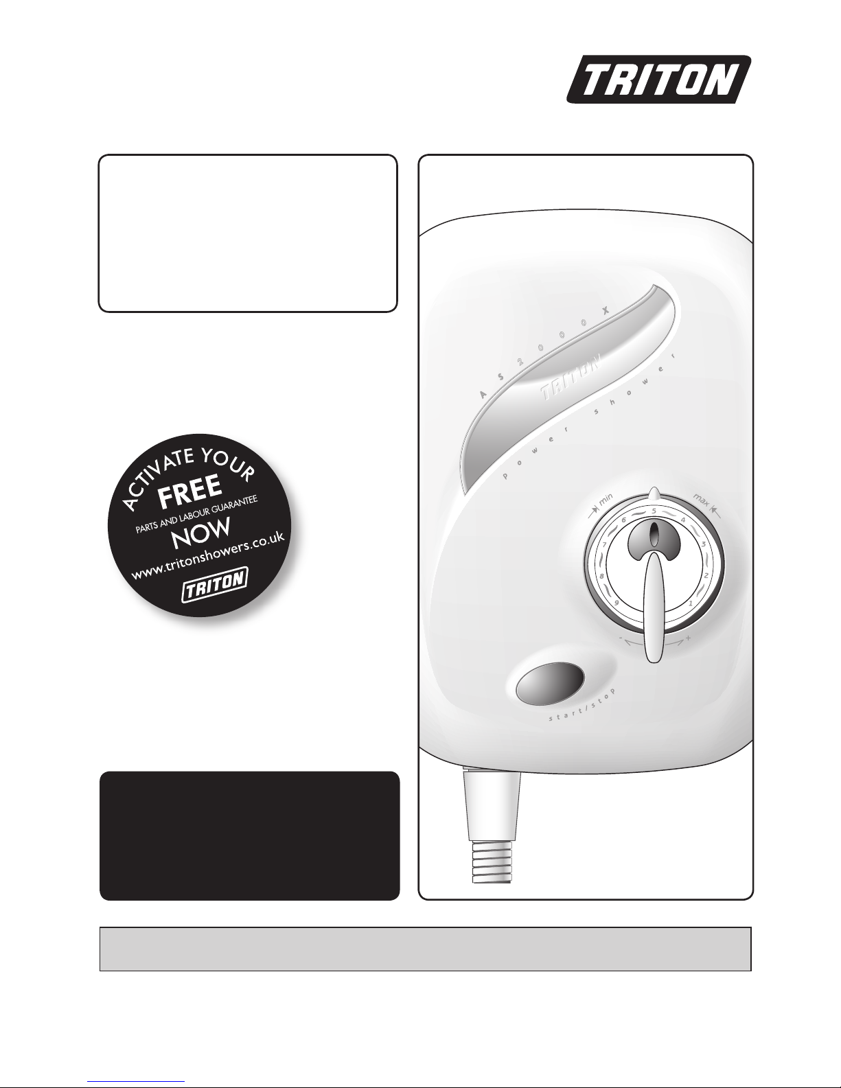
AS2000X
power shower
Page 2

Aquasensation AS2000X
CONTENTS Page
Plumbing and electrical notes ......................................................... 1
Introduction ................................................................................... 2
Safety warnings .............................................................................. 2
Main components .......................................................................... 3
Specifications .................................................................................. 3
Site requirements ........................................................................ 4 − 5
General installation notes ............................................................... 5
Siting of the shower ....................................................................... 6
Removing the cover........................................................................ 7
Plumbing connections ................................................................. 7 − 9
Fitting the shower to the wall ........................................................ 10
Electrical connections .................................................................... 11
Commissioning .......................................................................... 12 − 14
Fitting the riser rail .................................................................... 15 − 16
Operating the shower................................................................ 17 − 18
Adjusting the maximum temperature stop .................................... 18
Cleaning the filters ........................................................................ 19
Spare parts .................................................................................... 20
Fault finding .............................................................................. 21 − 22
Water/Cable entry points diagram .................................... 23
Guarantee, service policy, etc. ..................................................rear cover
To check the product suitability for commercial and multiple installations, please contact Triton’s
specification advisory service before installation.
Telephone:
Facsimile:
E mail:
0844 980 0730
0844 980 0744
technical@tritonshowers.co.uk
Page 3

Aquasensation AS2000X
1
1 PLUMBING NOTES
1.1 All installations must comply with Water
Regulations or Water Bylaws.
1.2 Supply pipes must be flushed to clear
debris before connecting the shower unit.
1.3 DO NOT connect the shower unit to
the mains cold water supply as it would
damage the unit and also, the installation
would be in breach of Water Regulations.
1.4 DO NOT use excessive force when making
connections to the flexible hose or
showerhead – finger tight is sufficient.
1.5 ALL plumbing connections are to be
completed and water supplies turned on
BEFORE switching on the electricity supply.
The shower must not be operated dry
without water.
1.6 DO NOT solder pipes or fittings within
300 mm of the shower appliance, as heat
transfer can damage components.
1.7 When installed, the top of the shower unit
must be at least 75 mm lower than the
base of the cold water storage cistern to
prevent the pump being run dry without
water.
1.8 A dedicated cold water supply must be
taken directly from the cold water cistern
to the shower. This draw-off must be on
the opposite side of the cistern to the float
operated valve to reduce the risk of air
entering the unit.
1.9 The action of the pump is to increase the
flow rate. If the supply pipework cannot
handle the resulting flow rate then:
1.9.1 The anticipated flow rate may not
be achieved.
1.9.2 Air may be drawn into the hot
supply from the vent pipe causing
spluttering and temperature fluctuations at
the showerhead.
1.10 Fullway isolating valves MUST be fitted
on the hot and cold water supplies to
the shower as an independent means
of isolating the water supplies should
maintenance or servicing be necessary. DO
NOT use stop taps or ball-o-fix type valves
which restrict flow.
2 ELECTRICAL NOTES
2.1 The installation must comply with BS 7671
‘Requirements for electrical installations’
(IEE wiring regulations). Make sure the
incoming hot and cold water supplies to
the shower are adequately earth bonded.
2.2 DO NOT turn on the electrical supply
until the plumbing connections have been
completed. Only then can the electricity be
switched on in order to power the solenoid
to turn water on to the shower when
commissioning. The shower must not be
operated dry without water.
2.3 The mains supply must be 230/240V, at
50Hz, connected to the unit via a double
pole switched 3 Amp fused connection
unit (not supplied) with a minimum 3 mm
contact separation gap in each pole.
2.4 In accordance with ‘The Plugs and Sockets
etc. (Safety) Regulations 1994’, this unit
is intended to be permanently connected
to the fixed electrical wiring of the mains
system.
2.5 Fuses do not give personal protection
against electric shock.
2.6 A 30mA residual current device (RCD)
MUST be installed. This may be part of the
consumer unit or a separate unit.
Page 4

Aquasensation AS2000X
2
INTRODUCTION
This book contains all the necessary fitting and
operating instructions for your Triton Power
Shower. Please read them carefully.
The shower installation must be carried out by
suitably competent person and in sequence of
this instruction book.
Care taken during the installation will ensure a
long and trouble free life from your shower
IMPORTANT: All plumbing connections must
be completed BEFORE making the electrical
connections.
Please read through the whole of this book
before beginning your installation.
IMPORTANT: The fittings on the pipe inlet
elbows are of the push-in type. The pipework
must be cut with a pipe cutter and all burrs
and rough edges removed from the end
of the tube. The fittings can be used with
copper and plastic pipe.
Where chrome plated pipe is used, remove
the first 25 mm of plating.
Note: The pump inside this product is rated
15 minutes on / 45 minutes off duty cycle.
SAFETY WARNINGS
a. DO NOT insert fingers into the push-in inlet
fittings. Doing so could cause injury.
b. Under no circumstances must this product
be connected to mains cold or hot water
supplies. Failure to comply will invalidate
the guarantee.
c. The shower MUST NOT be used if
suspected of being frozen.
d. The outlet of this appliance MUST NOT be
connected to any form of tap or fitting not
recommended by the manufacturer.
e. The showerhead cartridge MUST be cleaned
regularly to remove scale and debris.
f. This appliance MUST be earthed.
g. Switch off immediately at the isolating
switch if water ceases to flow during use.
h. DO NOT operate the shower outside the
guidelines laid out in ‘site requirements’.
i. DO NOT operate the shower if the
showerhead or spray hose becomes
damaged.
j. DO NOT restrict flow out of the shower by
placing the showerhead in direct contact
with your body.
Replacement parts can be ordered from Triton
Customer Service. See ‘spare parts’ for details and part
numbers.
WARNING!
The power shower does not contain
a thermostatic valve – it will not shut
off in the event of failure of either
the hot or cold water supplies.
A 30mA residual current device (RCD) MUST
be installed in all UK 230V electric and
pumped shower circuits. This may be part of
the consumer unit or a separate unit.
Page 5
Aquasensation AS2000X
3
Hot water temperature
Maximum temperature 65°C.
BS 6700 recommends that the temperature
of stored water should never exceed 65°C. A
stored water temperature of 60°C is considered
sufficient to meet all normal requirements and
will minimise the effects of scale in hard water
areas.
Maximum static inlet pressures
100 Kpa (1 bar) or 10m (supplies must be
gravity fed at nominally equal pressures).
Minimum static inlet pressure
0.75 Kpa (0.0075 bar) or 75mm (required to
prime the integral centrifugal pump).
Maximum supply head 10m.
SPECIFICATIONS
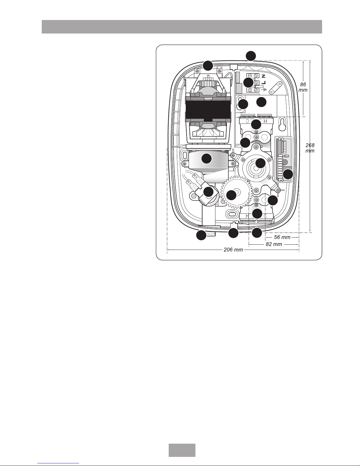
MAIN COMPONENTS
1. Top pipe entry and cable entry
2. Terminal block
3. Cover screw fixing
4. Motor retaining bracket
5. Rear pipe entry and cable entry
6. Wall fixing holes
7. Pipe inlet elbow - top
(contains single check valves)
8. Filter cover - top
9. Pump
10. PCB
11. Temperature control valve
12. Solenoid
13. Filter cover - bottom
14. Pipe inlet elbow - bottom
(contains single check valves)
15. Outlet
16. Bottom pipe entry
17. Potentiometer gear
Fig.1
1
2
3
4
5
6
7
8
9
10
11
12
13
14
15
16
17
Page 6
Aquasensation AS2000X
4
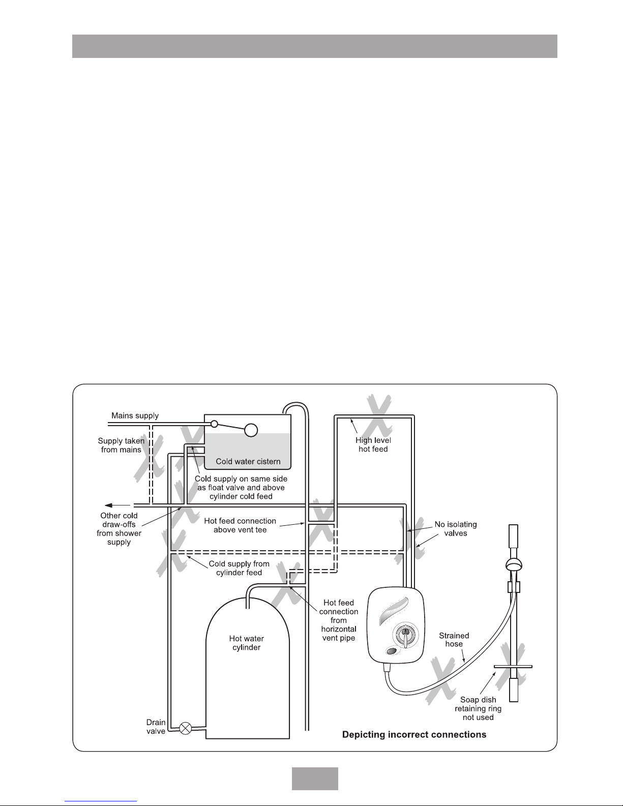
Fig.3 illustrates all the incorrect connections that
must be avoided.
All pipework to the shower unit must be routed
where it remains below the level of water in
the cistern. In the case of horizontal sections
of pipework in lofts, it may be necessary to
fit automatic air vents at high points on the
supplies to remove the possibility of air locks.
For the operation of the shower only, it is
recommended that the cold water storage
cistern is capable of holding at least 114 litres
(25 gallons). Where other hot and cold outlets
are likely to be in use simultaneously, the storage
capacity should be increased to 228 litres (50
gallons) in accordance with BS 6700.
Do ensure compliance with the Water
Regulations/Bylaws.
DO NOT connect to a combination cylinder
unless there is a guaranteed 114 litre cold supply
to the cylinder as the shower can deliver up to
14 litres per minute. It is advisable to check that
Mains supply
Isolating
valve
Cold water cistern
Vent pipe tee
Isolating
valve
Hot supply
Hot water
cylinder
Drain
valve
Other hot water
draw-offs
Alternative
connection
Shower unit
Ring main
25mm min
Isolating spur
(3A fused)
outside bathroom
Dedicated cold supply
10m
max
75mm
min
Isolating
valves
SITE REQUIREMENTS
Water
The installation must be in accordance with
Water Regulations/Bylaws and BS 6700.
For correct operation of this shower unit, both
hot and cold water supplies to the appliance
must be gravity fed, at nominally equal
pressures, from a cold water storage cistern and
a hot water storage cylinder.
The water circuit should be installed so that the
flow is not significantly affected by other taps
and appliances being operated elsewhere on the
premises.
Fig.2 shows a recommended installation where
the hot water supply for the shower is made
via a tee connection on the underside of the
horizontal section of pipework from the cylinder.
Alternatively, the connection can be taken from
the hot supply pipe to other outlets as long as it
is the first draw-off below the ventilation pipe tee.
Fig.2 (Diagrammatic view – not to scale)
Page 7
Aquasensation AS2000X
5
the infill rate from the float operated valve meets
the output requirements..
It is recommended that there is a minimum
of approximately 114 litres (25 gallons) of hot
water storage per appliance.
The shower MUST NOT be connected to the
mains cold water supply.
DO NOT use jointing compounds.
GENERAL INSTALLATION NOTES
1. DO NOT take risks with plumbing or
electrical equipment.
2. DO NOT install this unit in a position where
it could become frozen.
3. Isolate electrical and water supplies BEFORE
proceeding with installation work.
4. Shower control MUST be fed from a cold
water storage cistern and hot water cylinder
that provides nominally equal pressures.
Fig.3 (Diagrammatic view
not to scale)
5. The unit must be mounted onto the finished
wall surface (on top of tiles).
DO NOT tile up to the unit after fixing to
the wall.
6. If installing with rear inlet supplies, it is
recommended the supply pipework is sealed
to the wall so as to prevent water from
leaking back into the wall.
7. In solid wall installations, the supply
pipework should be housed within
ducting in order to allow some free lateral
movement when making connections and
to ensure compliance with requirements of
accessibility of pipes and pipe fittings.
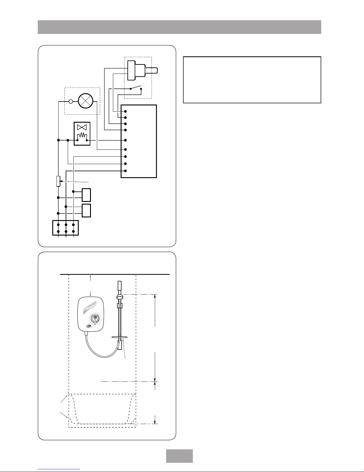
Fig.4 shows a schematic wiring diagram of the
unit.
Page 8
Aquasensation AS2000X
6
Shower can
be mounted
either side of
the riser rail
Spill-over
level
Ceiling
Use soap dish
retaining ring
Height of
sprayhead
and shower
to suit user’s
requirement
Shower unit
must not be
within an area
1 metre
from base
Space for cover
screw access
Fig.5
SITING OF THE SHOWER
IMPORTANT: If fitting to a tiled wall, always
mount the unit on the surface of the tiles.
NEVER tile up to the unit.
Refer to fig.5 for correct siting of the shower.
Position the unit vertically where it will NOT
be in direct contact with water from the
showerhead.
Note: Allow sufficient room between the ceiling
and the shower unit to access the top cover
screw.
Position the shower and showerhead on the wall
so that all controls can be comfortably reached
when using the shower.
The showerhead and riser rail can be positioned
either side of the shower unit.
Note: Water Regulations require the showerhead
be ‘constrained by a fixed or sliding attachment
so that it can only discharge water at a point
not less than 25 mm above the spill-over level
of the relevant bath, shower tray or other fixed
appliance’. The use of the supplied soap dish will
in most cases meet this requirement, but if the
showerhead can be placed within a bath, basin
or shower tray, then a device must be fitted to
prevent back-flow.
L E N
Potentiometer
Switch
Solenoid
Motor
Capacitor 2
RFI suppression coil
Capacitor 1
PCB
Thermal
fuse
Fig.4 (schematic view )
WARNING!
The shower must not be positioned
where it will be subject to freezing
conditions.
Page 9
Aquasensation AS2000X
7
Fig.6
REMOVING THE COVER
To remove the cover, first pull off the cover trim
(fig.6) to reveal the retaining screw.
Undo the screw and pull off the inner
temperature control. Now remove the outer flow
control assembly comprising of the flow control,
maximum temperature stop and temperature
disc (fig.7).
Note: If adjustment of the maximum
temperature stop is required, refer to section
’Adjusting the maximum temperature stop’.
Remove the two cover fixing screws – top and
bottom (fig.8).
Carefully lift the cover away from the backplate.
Lay aside the cover and screws until the unit is
fully installed.
Note: When removing the cover for future
maintenance purposes be aware of the lead
connecting the Start/Stop switch to the PCB
harness. To release, squeeze the connection
block arms and pull apart. DO NOT let the unit
dangle by the lead.
PLUMBING CONNECTIONS
Plumbing to be carried out before wiring
Note: The outlet of the shower must not be
connected to anything other than the hose and
showerhead supplied.
DO NOT use jointing compounds on any pipe
fittings for the installation.
When connecting pipework avoid using tight
90° elbows. Swept or formed bends will give
optimum performance.
Isolate the mains water supply to the cold water
cistern. Drain the hot and cold pipes by opening
all taps.
The hot water supply can be taken from the hot
supply pipe from the cylinder. Make sure that it
is the first draw-off below the ventilation pipe
tee in order to minimise the effects of water
draw-off elsewhere in the house (see fig.2).
Note: There must not be any other draw-offs
between the take-off point and the shower.
A dedicated cold water supply must be taken
directly from the cold water cistern to the
shower. This draw-off must be positioned
Temperature
disc
Flow control
Maximum
temperature
stop
Fig.7
Fig.8
Page 10

Aquasensation AS2000X
8
25 mm below the cold feed connection to the
hot water cylinder on the opposite side of the
cistern to the float operated valve (see fig.2).
This minimises air ingress into the pipework.
Plumbing options other than those outlined
in these fitting instructions could impair the
performance. For example, if hot and cold
connections are made after draw-off points
to other outlets, (eg. washing machine, taps,
etc.) it could result in unstable flows and
temperatures should other appliances operate at
the same time.
Run the hot and cold pipework to the shower
position, making sure that the pipework does
not rise above the level of water in the cold
cistern at any point to avoid air locks. Under
normal site conditions 15 mm pipework will be
adequate.
Decide the position of the shower. Cut the
pipework to the dimensions relevant to the
chosen direction of water entry into the shower.
IMPORTANT: For rear entry only, the supplied
elbows must be used. For ease of installation,
the backplate area adjacent to the top pipe
inlet must be cut out, including the top left
wall fixing hole.
When fitting the elbows to incoming pipework,
ensure the elbow collets are fully engaged with
the pipe.
Dimensions are shown in fig.9 and fig.10.
Note: The pipe inlets are marked for hot and
cold connections – left-hand side for hot inlet on
bottom entry (fig.11), but right-hand side for
hot inlet on top or rear entry (fig.12).
IMPORTANT: The fittings on the inlet elbows
are the push-in type. The pipework must be
cut with a pipe cutter and all burrs and rough
edges removed from the end of the tube. The
fittings can be used with copper and plastic
pipe.
If using chrome plated copper pipe, remove
the first 25 mm of plating completely from
the connecting surfaces. If not completely
removed then the collet will not grip the pipe
and under pressure the pipe may be forced
out.
Fig.9
Top
19 mm
26 mm
Cold
Hot
Area of
backplate
to remove
Wall
19 mm
34 mm
26 mm
Rear edge
of
backplate
Hot Cold
Wall
Rear
23.5 mm
Bottom
Fig.10
Page 11

Aquasensation AS2000X
9
Note: Pipework must be clipped or fixed to the
wall so that it cannot be moved or removed
without the aid of a tool.
Note: The pipe inlets contain filters. These
should be periodically removed and cleaned
in order to maintain the performance of the
shower. See section ‘cleaning’ on how to access
the filters.
IMPORTANT: The inlets contain check valves,
so before completing the connection of the
water supplies to the shower flush out the
pipework to remove all swarf and system
debris that may cause damage to internal
parts. This can be achieved by connecting
a hose to the pipework and turning on the
water supplies long enough to clear the
debris to waste.
IMPORTANT: Two factory fitted blanking
plugs are fitted to the top pipe inlets. These
should be left in position if bottom pipe entry
is required.
For top or rear pipe entry, the two plugs
MUST be removed and refitted into the
bottom pipe inlets. Failure to fit the
blanking plugs will result in the unit working
erratically.
Insert the pipe removal tool supplied between
the flange of the plug and the grey collet and
lever the plug outward (fig.13). Whilst holding
back on the collet, pull out each plug by hand.
When refitting the plugs in the bottom pipe
inlets, make sure they are pushed fully home.
Note: The unit is supplied with a splash guard
(fig.14) to prevent water ingress when top
entry pipework is used. If fitting top entry
pipework, make sure the splash guard is
correctly fitted (fig.14) before replacing the
cover.
Bottom
(rising)
supply
Top
(falling)
or rear
supply
Hot
side
Hot
side
Top
(falling)
or rear
supply
Hot
side
Fig.11
Fig.12
Blanking
plug
Fig.13
Splash guard
Fig.14
Page 12

Aquasensation AS2000X
10
FITTING THE SHOWER TO THE WALL
IMPORTANT: Before fitting the shower,
make sure the pipework is flushed out to
remove all debris, flux, etc.
For top pipe entry or top cable entry, remove
the relevant cut-outs by either breaking out or
by using a knife or junior hacksaw (fig.15).
If top entry for both pipe and cable is required,
then additionally remove the shaded area
(fig.15) by using a knife or junior hacksaw.
For bottom pipe entry, remove the cut-out and
break off the two circular parts (fig.16). Replace
the cut-out.
For rear pipe entry only, the supplied elbows
must be used with the necessary portion of
backplate cut away as shown in fig.9.
It will be necessary if rear cable entry is required,
for conduit or other routing of the electrical
cable to be completed before fixing the shower
to the wall.
Offer the backplate unit up to the completed
pipework and manoeuvre so that the end of the
pipes enter fully into the inlet fittings.
Mark positions for wall fixing holes using
backplate as template (fig.17). Note that four
fixing holes are provided but using only two
should be adequate for most site conditions.
Using the pipe removal tool supplied, push back
and hold the collets from the pipework (fig.18)
to disengage the pipework from the inlet elbows.
Remove unit from the wall.
Drill and plug the wall.
(An appropriate drill bit should be used. If the
wall is brick, plasterboard or a soft building block,
appropriate wall plugs and screws should be fitted).
Note: If fitting rising supplies to the unit, ensure
debris does not enter the pipes when drilling the
wall.
Offer the backplate unit up to the completed
pipework and manoeuvre so that the end of the
pipes enter fully into the inlet fittings.
Check the backplate is square and the fixing
holes are aligned (fig.17).
Secure to the wall with fixing screws supplied.
Remove shaded area
Cut out
for cable
Fig.15
Fig.16
Fig.17
Page 13

Aquasensation AS2000X
11
ELECTRICAL CONNECTIONS
The supply cable must conform to relevant
tables in current IEE regulations. In most cases
1 mm² twin and earth will be adequate.
The electrical rating of the shower is on the
rating label within the unit.
SWITCH OFF THE ELECTRICITY SUPPLY AT
THE MAINS.
Cable entry points are shown in fig.1. Conduit
entry can only be from the rear.
Route the cable into the shower, taking care to
avoid the area of the wall fixings and connect to
the terminal block (fig.19) as follows:
Earth cable to terminal marked E
Neutral cable to terminal marked N
Live cable to terminal marked L
IMPORTANT: Fully tighten the terminal block
screws and check that no cable insulation is
trapped under the screws.
Note: The supply cable earth conductor must
be sleeved.
The earth continuity conductor of the electrical
installation must be effectively connected
electrically to all exposed metal parts of other
appliances and services in the room in which the
shower is to be installed, to conform to current
IEE regulations.
Note: Fuses do not ensure user protection
against electric shock. In the interest of electrical
safety, all mains electric and pumped showers
should be fitted with a 30mA residual current
device (RCD). This may be part of the consumer
unit or a separate unit.
DO NOT switch on the electricity supply until
the water has been turned on to the unit and
connections have been tested for leaks.
IMPORTANT: The cover may be left off
initially only for commissioning.
Fig.18
Terminal block
Fig.19
WARNING!
This unit must be earthed. Isolate the
supply before starting.
Page 14

Aquasensation AS2000X
12
COMMISSIONING
The first operation of the shower is intended to
flush out any remaining system debris and to
ensure water is purged through the unit. This
operation must be carried out with the flexible
hose screwed to the shower outlet but without
the sprayhead attached.
Make sure the outlet of the flexible hose is
directed to waste.
Check the isolating valves controlling the water
supply to the unit are fully open.
Note: There is no need to fit the cover at
this stage but be aware of live parts when the
electricity is switched on temporarily.
Fit the temperature control onto the splined
spindle (fig.20).
On the PCB, make sure the commissioning link is
positioned on the middle two pins (fig.21).
Switch on the electric supply at the isolating
switch. Water will begin to flow under gravity
pressure.
Once the unit has been commissioned,
disconnect the electricity supply before removing
the commissioning link.
In order to dispel air and to prime both supplies
to the shower unit, turn the temperature control
several times within its rotational limits. ONCE
WARNING!
Before normal operation of the
shower, it is essential that the
commissioning and setup procedure
are correctly completed. Failure to do
so could cause the pump to run dry
without water and invalidate your
guarantee.
WARNING!
Be aware of live parts in the unit
when the electricity is switched on.
DO NOT tamper with any parts and
DO NOT deviate from the following
instructions.
Temperature control
Fig.20
Commissioning
link
Fig.21
Cold
Hot
Fig.22
Fig.23
Page 15

Aquasensation AS2000X
13
RESISTANCE IS FELT, DO NOT FORCE THE
CONTROL FURTHER.
Note: The temperature control rotates less than
one complete turn (fig.22). DO NOT force it
beyond these limits.
To stop the water flow, switch off the electricity
supply at the isolating switch.
Check for leaks in the pipework and remedy
if necessary. If rear entry has been used then
seal around pipes with mastic to prevent the
possibility of water entering the wall cavity.
DO NOT use plaster as this could cause difficulty
if maintenance is required later.
Setup procedure
MAKE SURE THE ELECTRICITY TO THE UNIT IS
SWITCHED OFF.
Pull off the temperature control. Remove the
commissioning link from the PCB (fig.23) and
store safely for future use.
Inside the cover, attached to the flow control
potentiometer is a 4-wire lead. Fit the connector
on the end of this lead to the 4 pins on the PCB
(fig.24) – it can fit either way.
Make sure the potentiometer control is rotated
fully anti-clockwise (fig.25).
Replacing the cover
Offer the cover to the backplate unit. Inside
the cover, attached to the stop/start switch is
a two wire lead. The socket on the end of this
lead must connect to the plug attached to the
backplate unit (fig.26).
Fit the cover, making sure the connector is fitted
to the PCB and the wires are clear of obstructions.
Secure with the top and bottom fixing screws
(fig.8).
WARNING!
Once the unit has been commissioned,
turn off the electricity supply at
the mains before removing the
commissioning link.
Fig.24
Fig.25
Fig.26
Page 16

Aquasensation AS2000X
14
With your fingers, rotate the valve spindle fully
anti-clockwise (fig.27) to the fully hot position.
Replace the flow control so that it aligns with
the ‘min’ position.
Fit the temperature disc (it will only fit one way)
and maximum temperature stop (fig.28).
Note: If adjustment of the maximum
temperature stop is required, refer to section
’Adjusting the maximum temperature stop’.
Replace the temperature control onto the valve
spindle. Make sure the pointer aligns with
setting ‘9’ on the temperature disc (fig.29).
Secure with the retaining screw and fit the cover
trim.
Switch on the electricity supply at the isolating
switch. Make sure both water supplies are still
turned on.
Once the installation of the riser rail is complete,
the shower is ready for normal operation.
Fig.29
Flow control
Temperature
disc
Temperature
control
Retaining
screw
Cover
trim
Maximum
temperature
stop
Fig.28
Fig.27
Page 17

Aquasensation AS2000X
15
*FITTING THE RISER RAIL
Decide the position for the rail on the wall within
the shower area. Proceed as follows:
Fit the showerhead holder onto the riser rail.
The correct orientation of the holder is when the
showerhead holder is sloping DOWN (fig.30).
To fit the showerhead holder onto the riser
rail unit, press and hold the button on the
underneath of the showerhead holder to release
the locking mechanism, then slide onto the rail.
Slide the supplied soap dish onto the riser rail
below the showerhead holder (fig.31).
Slide the top and bottom finishing trims onto the
riser rail (fig.32).
Push the two fixing brackets into the ends of the
riser rail (fig.33).
Offer the rail assembly to the wall (fig.34).
Using the brackets as templates, mark two upper
holes and two lower holes. Note there are four
provisions for screws per bracket – select the two
most suitable for your requirements. Make sure
the rail is aligned vertically.
Drill and plug the wall.
(An appropriate drill bit should be used. If the
wall is brick, plasterboard or a soft building block,
appropriate wall plugs and screws should be fitted).
Screw to the wall.
Slide the finishing trims onto the brackets. Make
sure the lug on each rail bracket end engages
into the slot on the fatter end of each trim before
push fitting the thinner ends in place (fig.35).
WARNING!
Check there are no hidden cables or
pipes before drilling holes for wall
plugs. Use great care when using
power tools near water. The use of
a residual current device (RCD) is
recommended.
Fig.33
Fig.30
Fig.32
Fig.31
Fig.34
*All kits are for illustration purposes only and are not
supplied unless otherwise stated.
Page 18

Aquasensation AS2000X
16
Washers
Shower
Showerhead
Showerhead
Holder
To remove a trim, push a small screwdriver or
similar through the slot in the trim end and
carefully pull away from the wall bracket.
Slide the soap dish down the rail so that its
bracket engages on top of the lower finishing
trim.
Adjusting the showerhead holder
To adjust the height, press the button
underneath the holder to release the locking
mechanism (fig.36). Still pressing the button,
move the holder up or down to suit user’s
requirement.
Fitting the hose and showerhead
Feed the flexible hose through the soap dish
aperture (fig.37) so the dish acts as a retaining
ring (Water Regulations).
Screw the flexible hose to the shower outlet and
showerhead, checking the supplied washers
are in place at both ends of the flexible hose
(fig.38).
Place the showerhead into the holder and check
that it fits correctly (fig.39).
Note: The holder is slightly tapered and the
showerhead and hose will only fit from one
direction.
IMPORTANT: It is the conical end of the hose
which grips into the holder. The showerhead
will not fit in the holder without the hose
attached. At this stage, disconnect the
showerhead and lay aside until the shower
unit has been commissioned.
CAUTION: This appliance is not intended
for use by persons (including children)
with reduced physical, sensory or mental
capabilities, or lack of experience and
knowledge, unless they have been given
supervision or instruction concerning use of
the appliance by a person responsible for
their safety.
Children should be supervised to ensure that
they do not play with the appliance.
Fig.35
Fig.37
Fig.39
Fig.36
Fig.38
Page 19

Aquasensation AS2000X
17
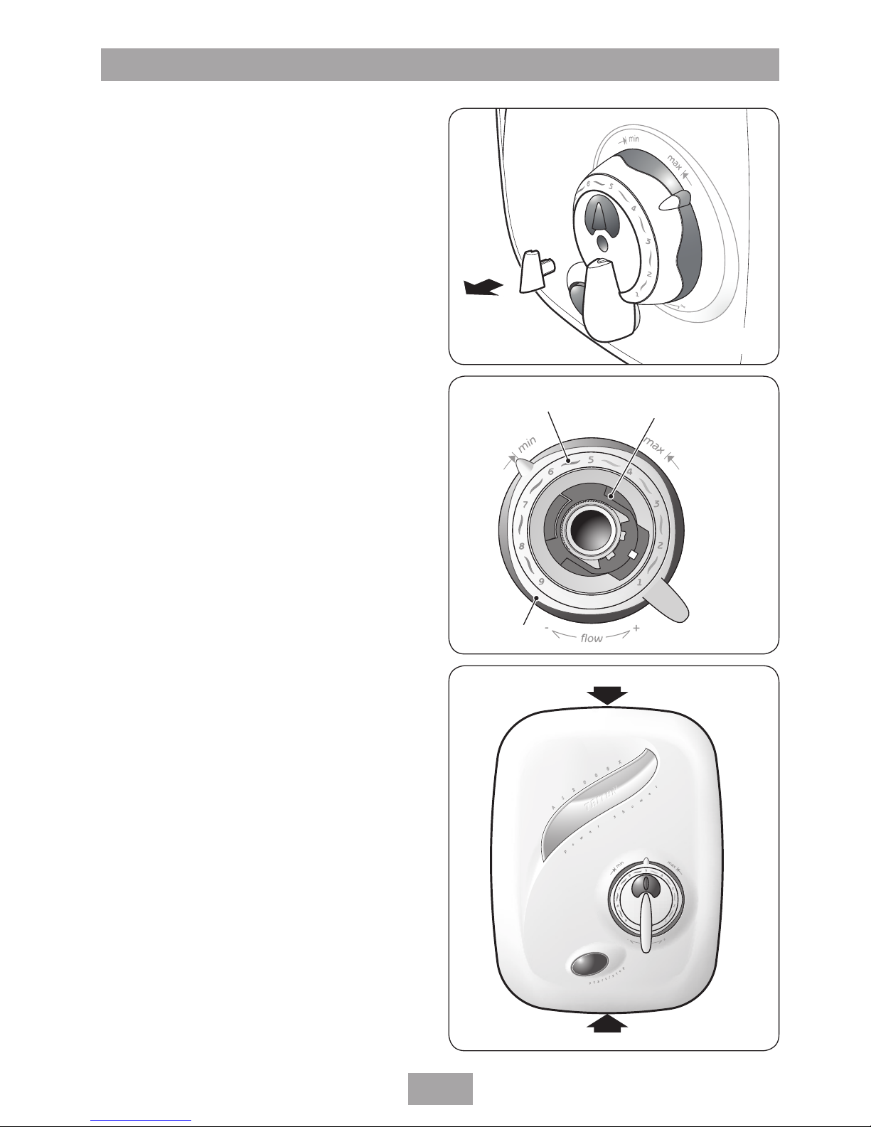
OPERATING THE SHOWER
Check all plumbing and electrical supplies are
connected and switched on.
To start the shower, press the ‘Start/Stop’ button
(fig.40).
Adjust the control (fig.41) until the flow rate is
satisfactory.
For maximum flow, turn the flow control fully
anti-clockwise. For minimum flow, rotate the
flow control fully clockwise.
To adjust the temperature rotate the control
(fig.42). The temperature is numbered for ease
of use. The temperature ranges from-‘1’ – fully
cold to ‘9’ – fully hot.
Once the preferred temperature is reached, no
further adjustment is required, providing the hot
and cold water supplies remain constant.
To stop the shower, press the ‘Start/Stop’ button
once more. This stops the pump and water flow.
Unless the shower is to be used again
immediately, the shower should also be switched
off at the electricity isolating switch.
As a safety feature, the temperature control
has a built-in stop to prevent you accidentally
exceeding your highest desired temperature. If
adjustment is required see section ‘Adjusting the
maximum temperature stop’.
To override this stop, depress the button
(fig.43) while the control is up against the stop
and turn the control anti-clockwise to the higher
settings (pressing the button before the stop will
not operate the override mechanism even if the
control is turned with the button depressed).
To return to the normal temperature range just
turn the temperature control clockwise until it
is past the maximum temperature stop. Make
sure the temperature control is in the normal
temperature range when the shower is switched
off. The stop comes in a factory set position
based on 65°C stored hot water temperature.
Note: As the flow control is adjusted it is normal
for the sound of the pump to alter in pitch.
Temperature
control
Override
button
Fig.40
Fig.42
Fig.41
Fig.43
Page 20

Aquasensation AS2000X
18
ADJUSTING THE MAXIMUM
TEMPERATURE STOP
As a safety feature the shower has a built-in
maximum temperature stop to prevent you
accidentally exceeding your highest desired
temperature. This is set in the factory to provide
a maximum temperature based on the hot
and cold water supplies being 65°C and 15°C
respectively.
IMPORTANT: Only adjust the maximum
temperature stop when the hot water is at its
usual storage temperature.
Procedure
Rotate the temperature control to setting ‘9’ on
the temperature disc.
Remove the cover trim to reveal the retaining
screw (fig.44).
Undo the retaining screw and carefully pull off
the temperature control, making sure it is still
aligned to setting ‘9’.
Now remove the maximum temperature stop.
To increase the temperature stop setting,
reposition the mechanism anti-clockwise within
the arc of the grooves (fig.45).
To decrease the temperature stop setting,
reposition the mechanism clockwise within the
arc of the grooves (fig.45).
Replace the temperature control onto the valve
spindle. Make sure the pointer aligns with
setting ‘9’ on the temperature disc (fig.28).
Secure with the retaining screw and refit the
cover trim.
Fig.44
Maximum
temperature
stop
Increase stop position
Decrease stop position
Fig.45
Page 21

Aquasensation AS2000X
19
CLEANING THE FILTERS
Note: Turn off the electricity and both hot
and cold water supplies to the unit before
proceeding further.
To remove the cover, first pull off the flow knob
cover trim (fig.6) to reveal the retaining screw.
Undo the screw and pull off the temperature
control. Now remove the outer flow control
assembly comprising of the flow control,
maximum temperature stop and temperature
disc.
Remove the two cover fixing screws – top
and bottom (fig.8). Carefully lift the cover
away from the backplate. To release the
PCB connector, squeeze the connection block
arms and pull apart.
Remove the single retaining screw from either
the upper or lower filter cover (fig.46),
depending upon whether top/rear entry or
bottom entry is used. Pull off the filter cover.
Carefully hook out the filters together with ‘O’
rings. Thoroughly clean and replace making sure
the ‘O’ rings are in position.
Refit the filter cover and secure with the
retaining screw.
Make sure the potentiometer control is rotated
fully anti-clockwise (fig.25).
With your fingers, rotate the valve spindle fully
anti-clockwise (fig.26) to the fully hot position.
Fit the cover, making sure the PCB connector is
fitted and the wires are clear of obstructions. Secure
with the top and bottom fixing screws (fig.8).
Replace the flow control so that it aligns with
the ‘min’ position.
Fit the temperature disc (it will only fit one way)
and maximum temperature stop (fig.27).
Replace the temperature control onto the valve
spindle. Make sure the pointer aligns with
setting ‘9’ on the temperature disc (fig.28).
Secure with the retaining screw and fit the cover
trim.
Switch on the electricity supply to the unit and
then turn on both water supplies.
INSTRUCTIONS FOR INSTALLERS AND SERVICE ENGINEERS ONLY
Retaining screw
Filter cover
Filter
Filter
Upper filter shown Fig.46
WARNING!
Switch off the electricity supply
and turn off both hot and cold
water supplies to the unit before
proceeding further.
Page 22

Aquasensation AS2000X
20
SPARE PARTS
Ref. Description Part No.
1 Terminal block ........................... 22001320
2 Plastic inlet elbow plug x1 ......... 7052140
3 Pump and motor assembly ........ 84000130
4 Pipe inlet elbow ........................83305320
c/w filters and check valves
5 Temperature valve ..................... 83305280
6 Link pin ..................................... 22009060
7 PCB unit .................................... 7073738
8 Solenoid assembly .................... 22012190
9 Gear .......................................... 7052184
10 Filter (pair) ................................83305330
– Pipe trim ...................................7052146
– Pipe removing tool .................... 7052144
– Potentiometer harness ...............P09440900
– Bracket ...................................... 7052183
– Wire kit .....................................83311410
11 Cover assembly .........................P09440600
– Maximum temperature stop ......7052186
– Temperature control ..................P09441000
c/w override button
– Flow control .............................. 7053275
– Temperature disc .......................7053277
– Flow control trim .......................7053276
– Temp control cover trim ............7053280
– Rear entry elbow ....................... 22008180
11
1
3
4
5
6
7
8
9
10
2
Page 23

Aquasensation AS2000X
21
FAULT FINDING
IMPORTANT: Switch OFF the electricity at the mains supply and remove the correct circuit
fuse before attempting any fault finding inside the unit.
Symptom Cause Action/Cure
1.1.1 Turn the temperature control clockwise.
1.2.1 Turn the temperature control clockwise.
1.3.1 Remove filter and clean. If problem is with
check valve, contact Customer Service.
1.4.1 Isolate shower and consult a competent
plumber or contact Customer Service.
2.1.1 Turn temperature control anti-clockwise.
2.2.1 Turn temperature control anti-clockwise.
2.3.1 Turn shower off and wait for hot water
cylinder to reheat.
2.4.1 Remove filter and clean. If problem is with
check valve, contact Customer Service.
2.5.1 Turn shower off. Consult a competent
plumber or contact Customer Service.
3.1.1 Blown fuse. Check supply. Renew fuse. If it
fails again consult a competent electrician.
3.1.2 Power cut. Check other appliances and if
necessary, contact local Electricity Supply Co.
3.2.1 Consult a competent electrician or contact
Customer Service.
3.3.1 Thermal protection on motor has
operated. Allow appliance to cool and reset
itself. If it persists, contact Customer Service.
3.4.1 Remove cover and connect start/stop
switch.
1 Water too hot.
2 Water too cold.
3 Pump does not
operate.
1.1 Not enough cold water
flowing through shower.
1.2 Increase in the ambient
cold water temperature.
1.3 Cold inlet filter blocked
or check valve sticking.
1.4 Cold water supply
blocked or cut off.
2.1 Not enough hot water
flowing through shower.
2.2 Decrease in ambient
cold water temperature.
2.3 No hot water in the
storage cylinder.
2.4 Hot inlet filter blocked
or check valve sticking.
2.5 Hot water supply
blocked or otherwise cut off.
3.1 Interrupted power
supply.
3.2 Electrical malfunction.
3.3 Motor overheated.
3.4 Start/stop switch not
connected.
Any maintenance or repair to the shower must be carried out by a suitably
competent person.
Page 24

Aquasensation AS2000X
22
FAULT FINDING
Symptom Cause Action/Cure
4.1.1 Check water elsewhere in house and if
necessary contact the local Water Company.
4.2.1 Switch off shower and contact Customer
Service.
4.3.1 Clean showerhead.
4.4.1 Clean filters.
5.1.1 Isolate water to unit. Remove check valves.
Clean and replace.
6.1.1 Call Customer Service.
6.2.1 Call Customer Service.
7.1.1 Call Customer Service.
7.2.1 Replace pump.
8.1.1 Fit blanking plugs into unused inlets.
4 Water does not
flow or is reduced.
5 Cross flow of
hot and cold water
into system.
6 Water dripping
from showerhead
when turned off.
7 Pump is noisy or
air lock in pump.
8 Unit running
erratically.
4.1 Water supplies cut off.
4.2 Shower blocked or air
in the system.
4.3 Showerhead blocked.
4.4 Blocked filters.
5.1 Dirt/debris in check
valves.
6.1 Debris in solenoid
valve.
6.2 Potentiometer faulty.
7.1 Air lock in pump.
7.2 Worn pump bearings.
8.1 Blanking plugs not
fitted into unused inlets.
In the unlikely event of a fault occurring please contact Triton Customer service.
DO NOT remove the shower from the installation.
Page 25

Aquasensation AS2000X
23
Entry Points
Diagram Key:
Water Entry Points
Cable Entry Points
Page 26

Aquasensation AS2000X
24
Page 27

Aquasensation AS2000X
25
Page 28

Triton Showers
Triton Road
Nuneaton
Warwickshire CV11 4NR
Triton is a division of Norcros Group (Holdings) Limited
Customer Service: % 0844 980 0750
Trade Installer Hotline:
%
0844 980 0730
Fax:
0844 980 0744
www.tritonshowers.co.uk
E-mail: serviceenquiries@tritonshowers.co.uk
TRITON reserve the right to change product specification without prior notice. E&OE. © TRITON SHOWERS 2012
Extended Warranty AVAILABLE NOW. Call 0844 980 0740 for more details.
UK SERVICE POLICY
In the event of a product fault or complaint occurring, the following
procedure should be followed:
1. Telephone Customer Service on 0844 980 0750 having available,
your details including post code, the model number and power
rating of the product, together with the date of purchase and, where
applicable, details of the particular fault.
2. If required, the Customer Service Advisor will arrange
for a qualified engineer to call.
3. All products attended to by a Triton service engineer must be
installed in full accordance with the Triton installation guide
applicable to the product. (Every product pack contains an installation
guide, however, they can also be bought via our Customer Service Spares
Department).
4. Our engineer will require local parking and if a permit is required this
must be available to the engineer on arrival at the call.
5. It is essential that you or an appointed representative (who must
be over 18 years of age) is present for the duration of the service
engineer's visit. If the product is in guarantee you must produce
proof of purchase.
6. Where a call under the terms of guarantee has been booked and
the failure is not product related (i.e. scaling and furring, incorrect
water pressure, pressure relief device operation or electrical/plumbing
installation fault) a charge will be made. A charge will also be issued
if nobody is at home when the service engineer calls or adequate
parking/permit is not available.
7. If the product is no longer covered by the guarantee an up front
fixed fee will be charged before the site visit.
8. Should proof of purchase not be available on an “in-guarantee” call,
or should the service engineer find that the product is no longer
under guarantee, the engineer will charge the same fixed price and
the customer will be expected to pay the engineer before he leaves.
If payment is not made on the day an administration charge will be
added to the fixed charge.
9. If a debt is outstanding from a previous visit, or from any other Triton
purchase. Triton reserves the right to withhold service until the debt
has been settled.
10. Triton takes the health, safety and wellbeing of its employees very
seriously and expects customers to treat all staff members with respect.
Should any employee feel threatened or receive abuse, either verbally
or physically, Triton reserves the right to withhold service and will
support the employee with a legal prosecution.
Replacement Parts Policy
It is the policy of Triton Showers to maintain parts availability for the
duration of production and a period of 5 years thereafter in accordance
with industry standards. In the event of a spare part not being available a
substitute part will be supplied.
Spare parts can be ordered via our online spare parts store, or by
telephoning Triton Spares Department. Payment should be made by
credit/debit card (excluding American Express or Diners Card). Payment
can also be made by pre-payment of a pro-forma invoice, by cheque or
postal order.
Telephone orders are based on information given during of the call.
Before contacting Triton, please verify your requirements using the
information contained in the user guide. Triton cannot accept liability for
incorrect part identification.
TRITON STANDARD GUARANTEE
Triton guarantee this product against all
mechanical and electrical defects arising from
faulty workmanship or materials for a period of
one year for domestic use only, from the date of
purchase, provided that it has been installed by
a competent person in full accordance with the
fitting instructions.
Any part found to be defective during this
guarantee period we undertake to repair or replace
at our option without charge so long as it has been
properly maintained and operated in accordance
with the operating instructions, and has not been
subject to misuse or damage.
This product must not be taken apart, modified or
repaired except by a person authorised by Triton.
This guarantee applies only to products installed
within the United Kingdom and does not apply to
products used commercially. This guarantee does
not affect your statutory rights.
What is not covered:
1. Breakdown due to: a) use other than domestic
use by you or your resident family; b) wilful act
or neglect; c) any malfunction resulting from the
incorrect use or quality of electricity, gas or water
or incorrect setting of controls; d) failure to install
in accordance with this installation guide.
2. Repair costs for damage caused by foreign
objects or substances.
3. Total loss of the product due to non-availability
of parts.
4. Compensation for loss of use of the product or
consequential loss of any kind.
5. Call out charges where no fault has been found
with the appliance.
6. Call out charges where the water supply cannot
be isolated, this includes consequential losses
arising from unserviceable supply valves.
7. The cost of repair or replacement of pressure
relief devices, showerheads, hoses, riser rails
and/or wall brackets, isolating switches,
electrical cable, fuses and/or circuit breakers or
any other accessories installed at the same time.
8. The cost of routine maintenance, adjustments,
overhaul modifications or loss or damage arising
therefrom, including the cost of repairing
damage, breakdown, malfunction caused by
corrosion, furring, pipe scaling, limescale,
system debris or frost.
3-1-2012
 Loading...