

Page 1
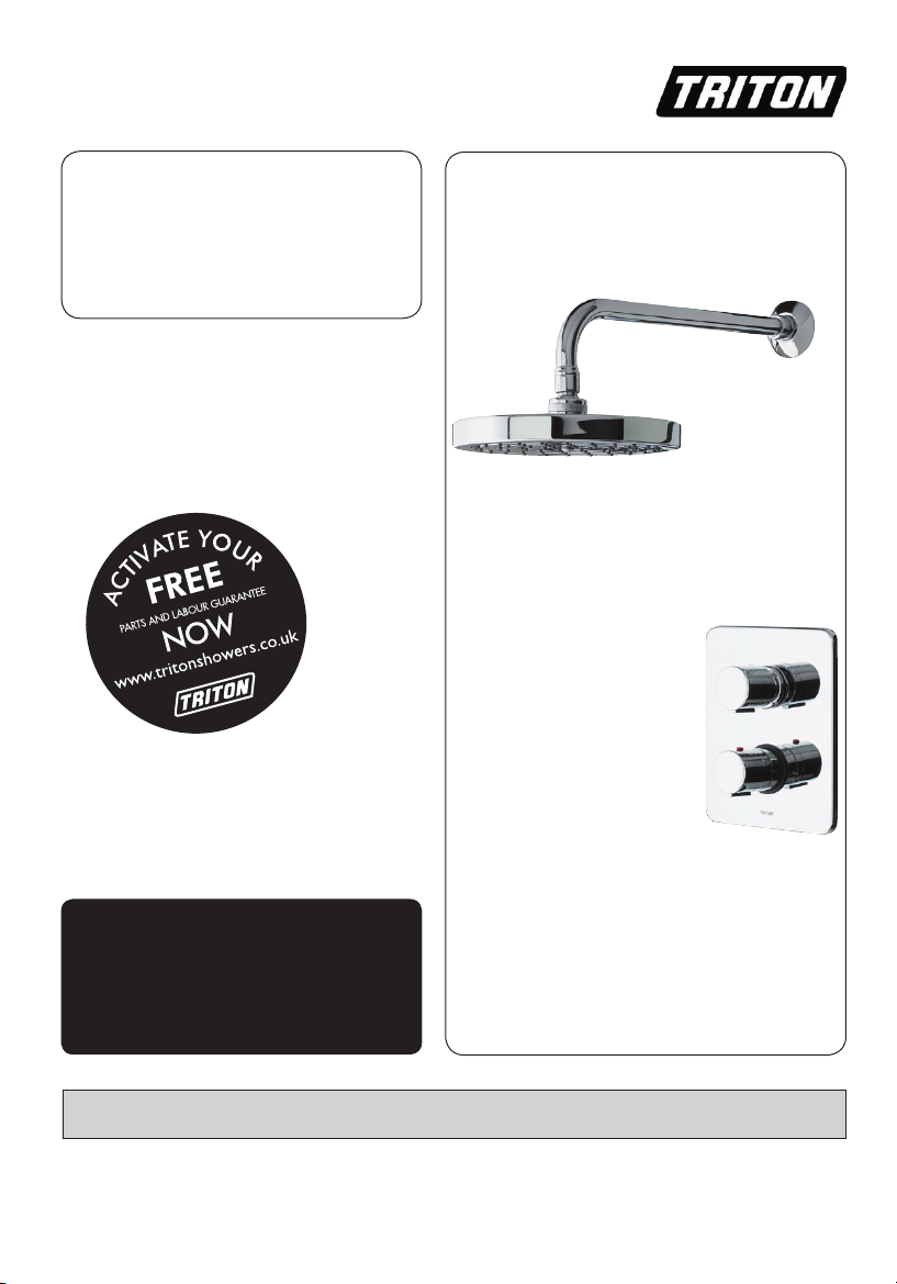
Antares
dual control
mixer shower
Installation and
operating
instructions
INSTALLERS PLEASE NOTE THESE INSTRUCTIONS ARE TO BE LEFT WITH THE USER
2180444C October 2005
Page 2

Dual control thermostati c mixer
CONTENTS Page
Introduction 1
Safety warnings 1
Main components 2
Site requirements 3
Typical suitable installations 4
Instantaneous water heater appliance capabilities 6
Preparing the mixer valve 7
Siting of the shower 7
Installation 8
Connecting the supply pipes 9
Fitting the fixed head pipework 10
Making good 10
Fitting the faceplate and controls 10
Commissioning 11
Operating the shower 12
Cleaning the filters 12
Cleaning 12
Spare parts 13
Fault finding 14
Guarantee, service policy, etc. rear cover
− 5
− 9
− 11
− 15
To check the product suitability for commercial and multiple installations, please contact
Triton’s specification advisory service before installation.
Telephone: 0870 067 3767
Facsimile: 0870 067 3334
E mail: technical@tritonshowers.co.uk
Page 3

Dual control thermostati c mixer
INTRODUCTION
This book contains all the necessary fitting and
operating instructions for your Triton Antares
dual control thermostatic mixer shower. Please
read them carefully. Read through the whole of
this book before beginning your installation.
The shower installation
a suitably competent person and in sequence of
this instruction book.
Care taken during the installation will provide a
long and trouble free life from your shower.
For best performance within the specified
running pressure range a minimum flow of eight
litres per minute should be available to both
inlets.
The mixer shower MUST NOT be subjected to
water temperatures above 80°C.
This mixer shower is designed for use with
traditional low pressure ‘gravity’ water systems,
using a cold water cistern and hot water cylinder
as well as for the higher pressure systems found
in the UK up to a maximum of 5 bar running
pressure.
IMPORTANT
with combination and multipoint hot water
appliances, the supplied flow restricters
MUST be installed.
This mixer shower is suitable for fully
modulating type combination boilers and multipoint hot water heaters. It is also suitable for
thermal storage, unvented systems and pumped
gravity systems.
IMPORTANT
instantaneous water heater, make sure it is
capable of delivering hot water at a minimum
switch-on flow rate of 3 litres per minute. At
flow rates between 3 and 8 litres per minute,
the appliance must be capable of raising the
water temperature to a minimum of 52°C.
Water temperature at the inlet to the mixer
must remain relatively constant when flow
rate adjustments are made (refer to the water
heater operating manual to confirm compatibility
with this mixer shower).
: When installing this mixer
: Before installing with a gas
MUST be carried out by
This mixer shower is supplied with an integral
single check valve and integral large area filter
in each inlet. Inlet connections are by ½” BSP to
22mm or 15mm compression (not supplied).
SAFETY WARNINGS
a Layout and sizing of pipework MUST be
such that when other services are used,
pressures at the shower control inlets do not
fall below the recommended minimum.
b DO NOT choose a position where the
shower could become frozen.
c DO NOT connect this mixer shower
to any form of tap or fitting not
recommended by the manufacturer.
d The showerhead MUST be regularly cleaned
to remove scale and debris.
e Conveniently situated service valves in
each inlet supply MUST be fitted as an
independent method of isolating the
shower should maintenance or servicing be
necessary.
f If it is intended to operate the shower
in areas of hard water (above 200 ppm
temporary hardness), a scale inhibitor may
have to be fitted. For advice on the Triton
scale inhibitor, please contact Customer
Service.
g DO NOT operate the shower outside
the guidelines as laid out in ‘site
requirements’.
Replacement parts can be ordered from Triton
Customer Service. See ‘spare parts’ for details and part
numbers.
Due to continuous improvement and updating,
specification may be altered without prior notice.
1
Page 4
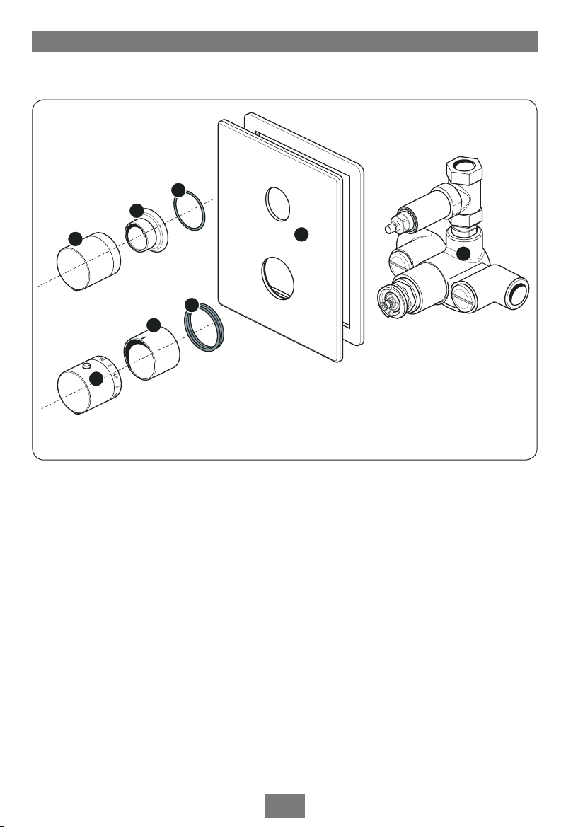
MAIN COMPONENTS
2
3
4
1
8
7
5
6
Dual control thermostati c mixer
Ref Description
1 Mixer valve
2 Trimplate
3 On/Off flow control knob
4 Threaded trim ring
5 Threaded trim ‘O’ ring seal
6 Temperature control knob
7 Trim ring
8 Trim ring seal
− Fixing screws/wall plugs
2
Page 5

Dual control thermostati c mixer
SITE REQUIREMENTS
The installation must be in accordance with
Water Regulations and Byelaws.
Running water pressure:
Gravity fed – 0.1 bar min.
1.0 bar max.
Mains fed – 1.0 bar min.
5.0 bar max.
Maximum static water pressure:
Gravity and mains – 10 bar
DO NOT connect the mixer shower to
a gravity hot supply and a mains cold
supply (or vice versa).
For the best performance within the specified
running pressure range a minimum flow of eight
litres per minute should be available to both
inlets.
While the mixer shower is operational (open
outlet), inlet pressures must not be capable of
exceeding 7 bar. For effective operation of the
internal seals, the maximum static pressure must
not be exceeded.
Note: On sites where the running pressure is
above 5 bar, the use of a suitably sized pressure
reducing valve fitted in the cold mains supply
pipework can provide nominally equal pressures
at the shower mixer.
The pipework should be installed such that the
flow is not significantly affected by other taps
and appliances being operated elsewhere on the
premises.
Note: Where thermal store systems and
instantaneous gas water heaters are used, if
excessive draw offs take place the boiler may
not be able to maintain an adequate output
temperature. This could result in the shower
temperature becoming noticeably cooler.
Water temperature requirements
Maximum hot water temperature = 80°C
Recommended maximum = 65°C
Minimum hot water temperature = 52°C
Maximum cold water temperature = 20°C
BS 6700 recommends that the temperature of
stored water should never exceed 65°C.
A stored water temperature of 60°C is
considered sufficient to meet all normal
requirements and will minimise the effects of
scale in hard water areas.
Temperature adjustment range
The mixed water temperature can be adjusted
from cold through to a top limit which must
be pre-set during installation with full anti-scald
protection throughout the range (35°C to 40°C)
providing the hot water temperature at the inlet
remains 10°C above the outlet temperature.
Should there be a loss of flow to either incoming
supply then water from the shower will stop or
be reduced to a trickle until both supplies are
restored.
3
Page 6

Dual control thermostati c mixer
Service
valves
Balanced cold mains supply
Cold mains supply
Mixer
Expansion
vessel
Pressure
reducing valve
Stop tap
Unvented
hot water
storage unit
Safety devices
not shown
Pipework to
fixed head
Pipework to
fixed head
CH flow
Cold
mains
supply
Hot water
CH return
Service
valves
Mixer
valve
Stop
tap
Expansion
vessel
Pressure
reducing valve
Combination
boiler
Fig.2 (diagrammatic view – not to scale)
Fig.3 (diagrammatic view – not to scale)
TYPICAL SUITABLE INSTALLATIONS
a) Instantaneous gas-heated systems,
e.g. combination boilers (fig.2)
The shower control MUST be installed with a
multipoint gas water heater or combination
boiler of a fully modulating design (i.e.
to maintain relatively stable hot water
temperatures).
A drop tight pressure reducing valve
MUST
be fitted if the supply pressures exceed 5 bar
running.
An expansion vessel (shown in
fig.2) MUST
be fitted, and regularly maintained, to ensure
the shower mixer is not damaged by excess
pressures. This may already be installed within
the boiler (check with manufacturer) and is in
addition to the normally larger central heating
expansion vessel.
The layout and sizing of pipework
MUST be
such that nominally equal inlet supply pressures
are achieved and the effects of other draw-offs
are minimised. The hot supply temperature
MUST remain a minimum of 10°C hotter than
the required blend temperature for optimum
performance.
b) Unvented mains pressure systems
(fig.3)
The shower control can be installed with an
unvented, stored hot water cylinder.
For systems with no cold water take off after the
appliance reducing valve, it will be necessary to
fit an additional drop tight pressure reducing
valve when the mains pressure is over 5 bar.
The drop tight pressure reducing valve must be
set at the same value as the unvented package
pressure reducing valve.
Note: An additional expansion vessel (fig.3)
may be required if a second pressure reducing
valve is installed. This does not apply to
packages with a cold take off after the pressure
reducing valve to the cylinder.
The layout and sizing of pipework
such that nominally equal inlet supply pressures
are achieved and the effects of other draw-offs
are minimised.
MUST be
4
Page 7

Dual control thermostati c mixer
Blender
valve
Flow
Cold mains supply
Hot
water
Stop tap
Expansion
vessel
Pressure
reducing valve
Return
Service
valves
Mixer
Boiler
Pipework to
fixed head
Pipework to
fixed head
Fixed head
Service
valves
Other draw-offs
Gate
valve
Ve
nt pipe
tee
Cold supply
Hot
supply
Alternative
connection
Mixer
Stop
tap
Cold
water
mains
supply
Hot
water
cylinder
Drain
valve
Cold water
cistern
1 metre
minimum
c) Mains pressurised thermal store
systems (fig.4)
Packages of this type, fitted with a tempering
valve (blender valve) can be used. A drop tight
pressure reducing valve MUST be fitted if the
supply pressures exceed 5 bar running.
An expansion vessel (shown in
fig.4) MUST be
fitted, and regularly maintained, to ensure the
unit is not damaged by excess pressures. This
may already be installed externally or internally
within the thermal store (check with thermal
store manufacturer).
d) Gravity fed systems (fig.5)
The shower control MUST be fed from a cold
water cistern and hot water cylinder providing
nominally equal pressures. There must be a
minimum of one metre head of water. The
minimum head distance is measured from the
base of the cold water cistern to top of the
showerhead (fig.5).
e) Pump assisted gravity systems (fig.6)
The pump must be fed from a cold water cistern
and hot water cylinder providing nominally
equal pressures. The pump must be capable of
maintaining a minimum running pressure of one
bar (fig.6).
Fig.4 (diagrammatic view – not to scale)
Fig.5 (diagrammatic view – not to scale)
5
Page 8

150 mm
min
Hot water
cylinder
Mixer valve
Service
valve
Cold supply
Hot supply
Alternative
supply
Cold
water
mains
supply
Ring main
Drain
valve
Isolating switch
or pull cord
switch (both
fused at 3A)
Gate
valve
Service
valve
Other
draw-offs
Stopvalve
Cold water
cistern
Pump
Pipework to
fixed head
Fixed head
Dual control thermostati c mixer
'C' clip
Wire filter
Combined check valve
and flow limiter
Filter cap
Fig.6
(diagrammatic view – not to scale)
Fig.7
INSTANTANEOUS WATER HEATERS
APPLIANCE CAPABILITIES
For best performance from the shower when
connected to an instantaneous water heater,
the appliance must be capable of raising
the temperature of the incoming water to a
minimum of 52°C (125°F) and delivering a flow
rate of not less than eight litres per minute.
Should simultaneous demands on the water
heater affect the water temperature then it is
advisable to fit the supplied flow limiters to
control the maximum flow.
To fit the flow limiters first remove the filter caps
from the hot and cold inlets. Each filter cap
contains a check valve and mesh debris filter,
held in place by a ‘C’ clip
(fig.7).
Carefully remove the ‘C’ clip and remove the
filter and check valve. Replace the existing check
valve with the combined check valve and flow
limiter supplied.
IMPORTANT:
When fitting the flow limiters
note the correct facing.
Refit the mesh filter and and secure in place
with the ‘C’ clip.
Repeat the process for the other filter cap. Screw
the filter caps back into the valve body.
With the flow limiters fitted and the system is in
use, the On/Off flow control should be turned
fully anti-clockwise to full flow setting.
6
Page 9

Dual control thermostati c mixer
Height of
showerhead
and shower
to suit user’s
requirement.
Pipework to
fixed head
Fixed head
PREPARING THE MIXER VALVE
WARNING!
The shower m ust not be positioned
where it w il l be subjected to
freezing conditio ns.
Check the contents to make sure all parts are
present.
Before installing, make sure all the openings on
the valve are carefully covered to stop ingress of
any debris etc.
The shower valve is suitable for installation in a
chased out cavity in a solid wall, a stud partition
wall, dry lined wall or fixing to a shower cubicle
or panel.
The hot and cold water pipes should not be
permanently attached to the wall within one
metre of the valve prior to installation to allow
for final adjustment of the valve position.
SITING OF THE SHOWER
Note: Suitable service valves (complying
with Water Regulations and Byelaws) MUST
be fitted on the hot and cold water supplies
to the shower as an independent means
of isolating the water supplies should any
maintenance or servicing be necessary.
Fig.8 (diagrammatic view – not to scale)
Refer to (fig.8) for correct siting of the shower.
Position the shower and showerhead on the wall
so that all controls can be comfortably reached
whilst using the shower.
The unit must be positioned vertically with the
outlet port at the top (marked with an ‘arrow’
on the brass body).
IMPORTANT
: The hot entry port is stamped
‘H’ on the mixer body.
7
Page 10

Dual control thermostati c mixer
INSTALLATION
a) General conditions
Note: The outlet of the shower MUST NOT
be connected to anything other than the
showerhead supplied.
DO NOT use jointing compounds on any
pipe fittings for the installation.
Suitable ½” BSP to 22mm or 15mm
compression fittings (not supplied)
used for connecting to the water supplies.
DO NOT solder fittings near the mixer
unit as heat can transfer along pipework
and damage the seals and thermostatic
components.
When connecting the pipework, avoid using
tight 90° elbows. Swept or formed bends will
provide the best performance.
The hot water inlet is stamped HOT and the
cold water inlet is identified COLD.
½” BSP straight or elbow male thread couplers
must be fitted to the inlet ports for either rising,
rear or falling hot and cold water supplies.
A ½” BSP straight coupler needs to be fitted to
the valve outlet.
Note: These couplers are NOT supplied.
Screw the couplers into the inlets and the
outlet of the valve. THE COUPLERS MUST BE
TIGHTENED AGAINST THE VALVE BODY. The
fittings will require PTFE tape or other means of
sealing.
Before starting the installation, make sure the
available depth of the recess or cavity is between
65 − 80mm as measured from the finished
surface.
The allowance for varying thickness of tiles up
to 10mm is accommodated to a limited degree
by the tolerance between the control knob and
trim ring.
b) Installation in a solid wall
Decide on the shower position and determine
whether the hot and cold water supplies will
enter the shower from the top (falling) or
bottom (rising) or rear.
The building depth should be at least 65mm
MUST be
deep from the finished wall surface.
As a guide for the size of hole, it should be large
enough to accept the valve complete with the
inlet and outlet fittings and also allow access for
connection to the pipework
Remove the plaster and brickwork to the
required depth and chase out any additional
areas of the wall to facilitate pipework to and
from the valve. Note that the valve body
requires a deeper recess (about 5mm greater)
than the inlet and outlet fittings.
Offer the valve body up to the wall and mark
the two fixing holes. Remove the valve and drill
and plug
body position.
Flush out the pipework in accordance
with Water Regulations and Byelaws.
Offer the valve up to the pipework and secure
with screws through the two fixing brackets on
the valve body.
Go to the ‘connecting supply pipes’ section.
the wall. Route the pipework to valve
(fig.9).
c) Installation in a hollow wall
Decide on the shower position and determine
whether the hot and cold water supplies will
enter the shower from the top (falling) or
bottom (rising) or rear.
When installing into a stud partition or other
hollow wall structures, the installer will need to
consider building rear supports or other options.
Such options are beyond the scope of this
guide.
The hollow cavity should be at least 65mm deep
from the surface of the wall.
Mark the route of the incoming and outgoing
pipework.
Take out the plasterboard (use the tiling shroud
as a guide). Offer the valve body up to the
fabrication and mark the two fixing holes.
Remove the valve and drill the holes. Route the
pipework to the valve position.
Flush out the pipework in accordance
with Water Regulations and Byelaws.
Offer the valve up to the pipework and secure
with screws through the two fixing brackets on
the valve body.
8
Page 11

Dual control thermostati c mixer
250mm approx.
Channel for incoming
pipework (rising shown)
Channel for outlet
pipe to fixed head o
r
bulkhead fitting
Recess at least
60mm deep
Recess for valve
body at least
65mm dee
p
Go to the ‘connecting supply pipes’ section.
d) Installation in a panel or cubicle
When installing into a panel or cubicle structure
the installer will need to consider building
supports or other options. Such options are
beyond the scope of this guide.
There should be at least 65mm space from the
surface of the panel to the rear of the valve
body.
IMPORTANT
must be available.
Decide on the shower position and determine
whether the hot and cold water supplies will
enter the shower from the top (falling) or
bottom (rising) or rear. Mark the route of the
incoming and outgoing pipework.
The control knobs require two holes to be cut
out of the panel or cubicle. Use the face plate
as a template to mark the hole positions then
extend further to allow access for the filters.
Route the pipework to valve position.
Flush out the pipework in accordance
with Water Regulations and Byelaws.
Offer the valve up to the pipework and secure
with screws through the two fixing brackets on
the valve body.
: Access to the rear of the valve
Fig.9
CONNECTING SUPPLY PIPES
Connect the hot water supply to the inlet
marked ‘H’ and connect the cold water supply
to the inlet marked ‘C’.
Tighten all compression fittings.
9
Page 12

Appropriate
fitting
Wa
ter pipe
Dual control thermostati c mixer
Fitting should
be flush with
the finished wall
Fig.10
Fig.11
Fig.12
FITTING THE FIXED HEAD
PIPEWORK
Complete the outlet pipework, ending in a
½” BSP x 15mm female thread elbow (fig.10).
Finish the wall so that it is flush with the fitting
(fig.11).
Note: This fitting is not supplied as variations
in installations require the selection of the most
suitable fitting.
MAKING GOOD
Fit the tiling shroud over the mixer body and
make good the wall, tiling etc. and around the
fixed head outlet.
Note that if the tiles are accurately cut to match
the profile of the shroud, then the faceplate will
seal around the hole in the tiles, and the valve
unit can be serviced without the need to break
any tiles.
Make sure the grout lines are flush with the tiles
in order to provide a smooth sealing surface for
the face plate.
FITTING THE FACEPLATE AND
CONTROLS
Insert the rubber trim seal into the temperature
opening of the face plate (fig.12).
Fit the face plate over the valve controls and
slide tight up to the wall. Make sure the rubber
seal stays in place as it slides over the trim. A
smear of liquid soap on the seal will ease this
procedure.
The face plate incorporates a silicon sponge
backing that seals against a smooth wall.
Fitting the temperature control
Temporarily fit the temperature control knob
onto the splined adaptor (fig.13).
DO NOT secure with the grub screw until
the commissioning procedure is complete.
Fitting the On/Off flow control
Insert the ‘O’ ring seal into the recess in the
back of the threaded trim ring (fig.14). Screw
the threaded trim ring onto the On/Off spindle
until it engages into the face plate opening.
10
Page 13

Dual control thermostati c mixer
‘O‘ ring seal
Threaded
trim ring
Make sure the ‘O’ ring is in place when tight to
the face plate.
Fit the On/Off
splined shank and tighten onto the spline with
the grub screw (fig.15).
flow control knob onto the
COMMISSIONING
CHECK THAT ALL SUPPLY PIPEWORK HAS BEEN
FLUSHED THROUGH BEFORE COMMISSIONING.
Make sure that both hot and cold water supplies
are fully open and at (or near to) their design
temperature and pressures and are within the
requirements as stated.
Make sure the temperature control knob
is rotated fully anti-clockwise (maximum
temperature setting).
Start the water flow by turning the flow control
anti-clockwise towards
Allow the shower to run at the maximum
temperature setting until the water temperature
has stabilised. Rotate the temperature control
knob until your desired maximum showering
temperature is reached.
The mixer valve is factory set to provide a
maximum outlet temperature of 38°C but this
should be checked on site to make sure the
setting has not been altered and also to ensure
user safety.
ON.
Fig.13
Fig.14
Fig.15
11
Page 14

Dual control thermostati c mixer
Fig.16
Fig.17
WARNING!
DO NOT use abrasive cleaners
and solvents or the surfaces may
become damaged.
To adjust the maximum temperature
override setting
Remove the temperature control by unscrewing
the grub screw (fig.16).
Turn the flow control fully anti-clockwise.
Once there is a steady flow running, adjust the
temperature valve spindle until the temperature
is about 40°C (turn clockwise for cold and anticlockwise for warm).
When you are satisfied with the temperature
setting turn off the flow control.
Refit the temperature control, checking that the
temperature stop aligns with the reference line
on the mixer valve body.
Secure in place using the grub screw.
OPERATING THE SHOWER
To start the shower, turn the On/Off flow
control fully to the left for maximum flow.
To stop the water flow, turn the On/Off flow
control fully to the right.
To adjust the water temperature, rotate the
temperature control – clockwise for a cooler
shower or anti-clockwise for a hotter shower.
CLEANING THE FILTERS
Turn off the water supplies before proceeding.
To access to the filters first remove the two
controls. Unscrew the threaded trim ring then
pull the face plate away from the wall.
Unscrew the filter cap
unclip the ‘C’ clip and remove the filter. Wash
the filter thoroughly under running water to
remove all debris. Replace the filter and ‘C’ clip
into the cap and screw the unit back into each
inlet, making sure the ‘O’ ring is in place.
Reassemble the face plate, threaded trim ring
and control knobs.
(fig.17) on each inlet,
CLEANING
When the controls and face plate require
cleaning, take care not to scratch them in the
process. Wash away any surface dust before
cleaning with soapy water.
12
Page 15

Dual control thermostati c mixer
3
4
1
7
5
2
6
7
SPARE PARTS
Ref. Description Part No.
1 Flow control knob 83307440
2 Temperature control knob 83307470
3 Adaptor 83308670
4 Face plate 86001320
5 Ceramic headworks 83307220
6 Thermostatic cartridge 83307340
7 Filter 83307240
13
Page 16

Dual control thermostati c mixer
FAULT FINDING
The following can be carried out by a competent person
Problem/Symptom Cause Action/Cure
1 Water too hot.
2 Water too cold.
3 High water
flow and/or poor
performance on a
mains fed system.
1.1 Temperature control
incorrectly commissioned.
1.2 Not enough cold water
flowing through shower.
1.3 Increase in the ambient
cold water temperature.
1.4 Cold water supply
blocked.
1.5 High volume of cold
water drawn off elsewhere.
2.1 Temperature control
incorrectly commissioned.
2.2 Not enough hot water
flowing through shower.
2.3 Decrease in the ambient
cold water temperature.
2.4 Insufficient hot water
supplies from the heating
system.
2.5 Hot water supply
blocked or restricted.
2.6 Flow limiter not fitted
(HP systems only).
3.1 Flow limiter not fitted.
1.1.1 Refer to ‘commissioning’ section.
1.2.1 Turn temperature control anti-clockwise.
1.3.1 Turn temperature control anti-clockwise.
1.4.1 Turn off shower and consult a competent
plumber or contact Triton Customer Service.
1.5.1 Reduce the simultaneous demand from the
supply.
2.1.1 Refer to ‘commissioning’ section.
2.2.1 Turn the temperature control clockwise.
2.3.1 Turn the temperature control clockwise.
2.4.1 Make sure heating appliance is set to
maximum or has sufficient stored hot water.
2.4.2 Make sure heating appliance is igniting by
trying a hot water tap elsewhere.
2.5.1 Turn off the shower and consult a competent
plumber or contact Triton Customer Service.
2.6.1 Fit flow limiters in the filter caps; see
‘instantaneous water heaters appliance capabilities’
3.1.1 Fit flow limiters in the filter caps; see
‘instantaneous water heaters appliance capabilities’)
.
.
4 Water does not
flow or shower
pattern collapses
when another
outlet is turned on.
4.1 Water supplies cut off.
4.2 Shower unit blocked.
4.3 Blockage in pipework.
4.4 Showerhead blocked.
4.5 System not capable of
supplying multiple outlets at
the same time.
4.1.1 Check water elsewhere in house and if
necessary contact local water company.
4.2.1 Inspect the inlet filters. Clean if necessary.
4.3.1 Turn off the shower and consult a suitably
competent plumber.
4.4.1 Clean showerhead.
4.5.1 Reduce the simultaneous demand.
4.5.2 Check stop/service valves are fully open.
4.5.3 Check if sufficient water pressure.
14
Page 17

Dual control thermostati c mixer
FAULT FINDING
The following is recommended for a professional qualified installer only
Problem/Symptom Cause Action/Cure
5 Water too cold.
6 Shower controls
noisy whilst in use.
7 Shower will not
shut off.
5.1 Running pressure
in excess of maximum
recommended.
6.1 Running pressure
in excess of maximum
recommended.
7.1 Pipework not flushed
before connecting the unit
(flow control damaged).
5.1.1 Fit a pressure reducing valve.
6.1.1 Fit a pressure reducing valve.
7.1.1 Renew flow control washer.
15
Page 18

Dual control thermostati c mixer
16
Page 19

Dual control thermostati c mixer
17
Page 20

In the event of a complaint occurring, the following
Service Policy
procedure should be followed:
1 Telephone Customer Service on
0870 067 3333 (0845 762 6591 in Scotland and
in Northern Ireland), having available the model
number and power rating of the product, together
with the date of purchase.
2 Triton Customer Service will be able to confirm
whether the fault can be rectified by either the
provision of a replacement part or a site visit
from a qualified Triton service engineer.
3 If a service call is required the unit must be fully
installed for the call to be booked and the date
confirmed. In order to speed up your request,
please have your postcode available when
booking a service call.
4 It is essential that you or an appointed
representative (who must be a person of 18 years
of age or more) is present during the service
engineer's visit and receipt of purchase is shown.
5 A charge will be made in the event of an aborted
service call by you but not by us, or where a call
under the terms of guarantee has been booked
and the failure is not product related (i.e. scaling
and furring, incorrect water pressure).
6 If the product is no longer covered by the
guarantee, a charge will be made for the site
visit and for any parts supplied.
7 Service charges are based on the account being
settled when work is complete, the engineer
will then request payment for the invoice. If this
is not made to the service engineer or settled
within ten working days, an administration
charge will be added.
Replacement Parts Policy
Availability: It is the policy of Triton to maintain
availability of parts for the current range of
products for supply after the guarantee has
expired. Stocks of spare parts will be maintained
for the duration of the product’s manufacture and
for a period of five years thereafter.
In the event of a spare part not being available a
substitute part will be supplied.
Payment: The following payment methods can be
used to obtain spare parts:
1 By post, pre-payment of pro forma invoice by
cheque or money order.
2 By telephone, quoting credit card (MasterCard
or Visa) details.
3 By website order, www.tritonshowers.co.uk
Triton Showers
Triton Road
Nuneaton
Warwickshire CV11 4NR
Triton is a division of Norcros Group (Holdings) Limited
TRITON STANDARD GUARANTEE
Triton guarantee this product against all mechanical
defects arising from faulty workmanship or materials
for a period of five years for domestic use only, from
the date of purchase, provided that it has been
installed by a competent person in full accordance
with the fitting instructions.
Any part found to be defective during this
guarantee period we undertake to repair or replace
at our option without charge so long as it has been
properly maintained and operated in accordance
with the operating instructions, and has not been
subject to misuse or damage.
This product must not be taken apart, modified or
repaired except by a person authorised by Triton.
This guarantee applies only to products installed
within the United Kingdom and does not apply to
products used commercially. This guarantee does
not affect your statutory rights.
What is not covered:
1 Breakdown due to: a) use other than domestic
use by you or your resident family;
b) wilful act or neglect; c) any malfunction
resulting from the incorrect use or quality of
water or incorrect setting of controls; d) faulty
installation.
2 Repair costs for damage caused by foreign
objects or substances.
3 Total loss of the product due to non-availability
of parts.
4 Compensation for loss of use of the product or
consequential loss of any kind.
5 Call out charges where no fault has been found
with the appliance.
6 The cost of repair or replacement of
showerheads, hoses, riser rails and/or wall
brackets or any other accessories installed at the
same time.
7 The cost of routine maintenance, adjustments,
overhaul modifications or loss or damage arising
therefrom, including the cost of repairing
damage, breakdown, malfunction caused by
corrosion, furring, pipe scaling, limescale, system
debris or frost.
Customer Service: % 0870 067 3333
Scottish and Northern Ireland
Customer Service: % 0845 762 6591
Trade Installer Hotline: % 0870 067 3767
Fax: 0870 067 3334
www.tritonshowers.co.uk
E mail: technical@tritonshowers.co.uk
TRITON reserve the right to change product specification without prior notice. E&OA. © TRITON SHOWERS 2008
 Loading...