

Page 1

MODEL 9100
AUTOMATED TELLER MACHINE
USER MANUAL
VERSION 1.0
TDN 07100-00080 04/2007
CORPORATE HEADQUARTERS:
522 E. Railroad Street
Long Beach, MS 39560
Phone: (228) 868-1317
Fax: (228) 868-0437
COPYRIGHT NOTICE
© 2002 - 2007 Delaware Capital Formation, Inc. All Rights Reserved. Triton Systems of Delaware, Inc.
is an operating company of Dover Electronics, Inc., a subsidiary of Dover Corporation (NYSE-DOV).
DOVER, the DOVER logo and the family of marks and TRITON, the TRITON logo and the Triton
family of marks are registered trademarks of Delaware Capital Formation, Inc., a wholly owned subsidiary of Dover Corporation.
RMA (RETURN MATERIAL AUTHORIZATION)
RETURN A DDRESS:
21405 Avenue “B”
Long Beach, MS 39560
Page 2

MODEL 9100 USER MANUAL
NOTICES
Copyright © Delaware Capital Formation, Inc., 2002 - 2007.
ALL RIGHTS R ESERVED
This publication is protected by copyright and all rights are reserved. No part of it may be reproduced or
transmitted by any means or in any form, without prior consent in writing from Triton Systems of Delaware, Inc.
The information in this publication has been carefully checked and is believed to be accurate. However,
Triton Systems of Delaware, Inc. assumes no responsibility for any inaccuracies, errors, or omissions
that may be contained in this document. In no event will Triton Systems of Delaware, Inc. be liable for
direct, indirect, special, incidental, or consequential damages resulting from any defect or omission in this
manual, even if advised of the possibility of such damages.
In the interest of continued product development, Triton Systems of Delaware, Inc. reserves the right to
make improvements in its documentation and the products it describes at any time, without notice or
obligation.
TRADEMARK A CKNOWLEDGEMENTS
Triton Connect is a trademark of Triton Systems of Delaware, Inc. VISA® is a registered trademark of
VISA of the United States and other countries.
ii
Page 3

MODEL 9100 USER MANUAL
CONTENTS
SECTION 1 - INTRODUCTION ........................................................................................ 1
WHAT’S IN THIS MANUAL .......................................................................................................................2
FEATURE HIGHLIGHTS ..............................................................................................................................3
STANDARD FEATURES ..............................................................................................................................4
SECTION 2 - BASIC OPERATION ................................................................................... 7
INTRODUCTION ........................................................................................................................................8
CONTROL PANEL LAYOUT ........................................................................................................................8
FUNCTION KEYPADS................................................................................................................................9
MAIN KEYPAD ....................................................................................................................................... 9
MENU-BASED OPERATION........................................................................................................................11
CUSTOMER TRANSACTIONS ....................................................................................................................... 12
VOICE-ENABLED TRANSACTIONS .............................................................................................................. 14
SECTION 3 - MANAGEMENT FUNCTIONS ....................................................................... 15
INTRODUCTION ........................................................................................................................................16
ACCESSING THE MANAGEMENT FUNCTIONS MENU ....................................................................................16
NEW OR MODIFIED MANAGEMENT FUNCTIONS ..........................................................................................17
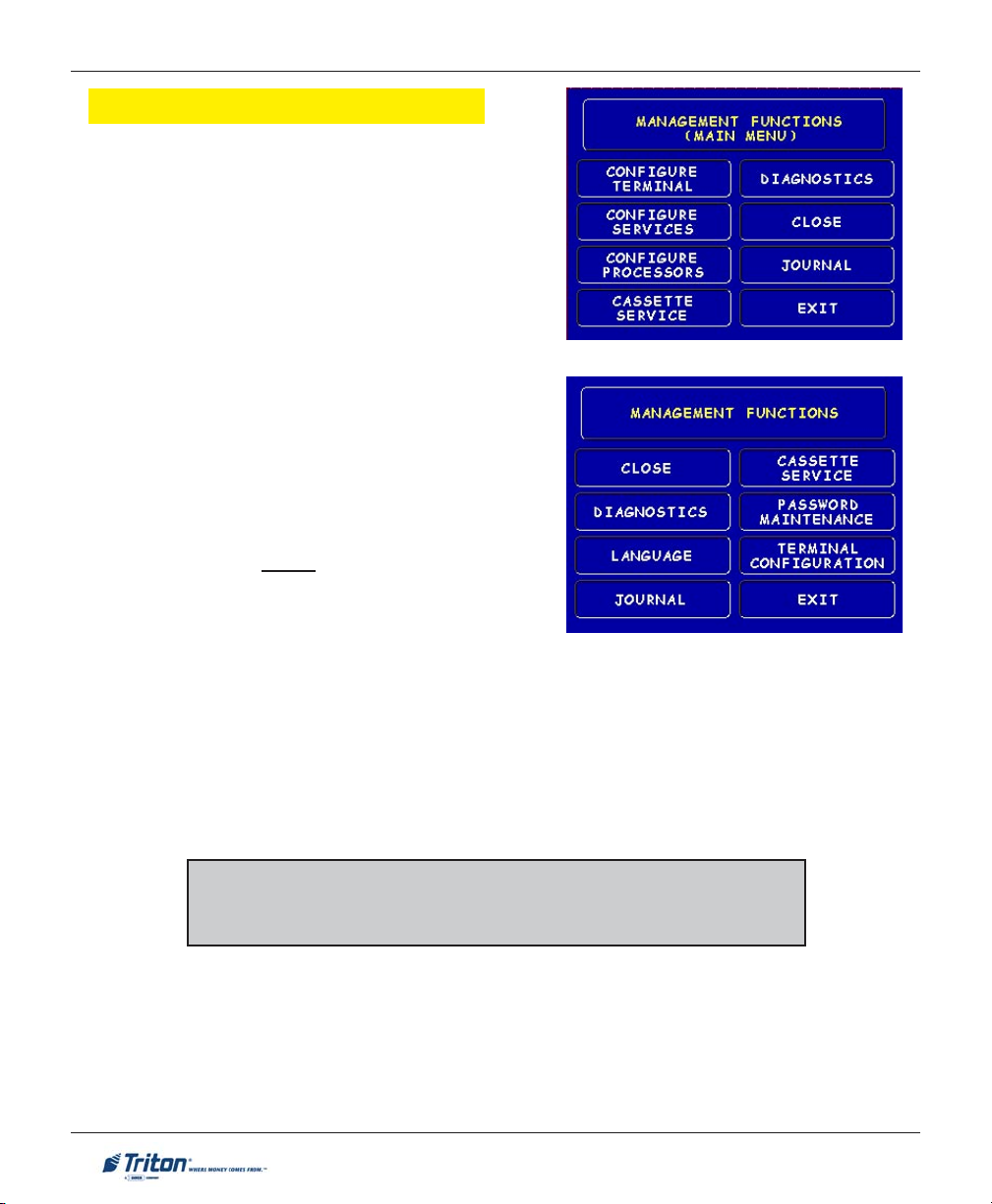
MAIN MENU .......................................................................................................................... 18
ONFIGURE TERMINAL ........................................................................................................... 19
C
CASSETTE SETUP ..............................................................................................................................19
DAT E / TIME FUNCTIONS ..................................................................................................................19
LANGUAGE IDIOMA ..........................................................................................................................19
PRINTER SETTINGS ...........................................................................................................................19
ATM MONITORING ......................................................................................................................... 19
PASSWORD MAINTENANCE ............................................................................................................... 19
MORE .............................................................................................................................................20
AD SCREENS .................................................................................................................................. 20
RANDOM / LEVEL PROZE COUPONS ...................................................................................................20
CHANGE MESSAGES ........................................................................................................................20
COMMUNICATION .............................................................................................................................20
ADJUST CONTRAST ...........................................................................................................................20
LOCAL ZIP CODE ............................................................................................................................. 20
MORE .............................................................................................................................................20
SPEECH ON / OFF ............................................................................................................................20
VIEW / MODIFY OPTIONS ................................................................................................................. 20
iii
Page 4

MODEL 9100 USER MANUAL
CONTENTS
CASSETTE SETUP ............................................................................................................................ 21
RELEARN BILL THICKNESS ............................................................................................................... 21
INTERNATIONAL CURRENCY .............................................................................................................. 21
MAXIMUM A MOUNT (CASH) ............................................................................................................. 21
MAXIMUM A MOUNT (NON-CASH) .....................................................................................................21
CASSETTE PARAMETERS ....................................................................................................................21
FAST CASH A MOUNTS ...................................................................................................................... 21
MORE .............................................................................................................................................21
LOW CURRENCY .............................................................................................................................. 21
EXTENDED A MOUNT ........................................................................................................................ 21
CASSETTE PARAMETERS .................................................................................................................. 22
SET BILL D IMENSIONS .....................................................................................................................22
VALUE ............................................................................................................................................22
TYPE ..............................................................................................................................................22
SERVICE ..........................................................................................................................................22
CURRENCY DAT A ............................................................................................................................. 22
CASSETTE ........................................................................................................................................22
DESCRIPTION ...................................................................................................................................22
CONFIGURE PROCESSORS ................................................................................................. 2 3
PROCESSOR NAME ........................................................................................................................... 23
TERMINAL ID ................................................................................................................................. 23
KEY MANAGEMENT ........................................................................................................................23
COMMUNICATION TYPE ....................................................................................................................23
COMMUNICATION NUMBERS ..............................................................................................................23
SENT TERMINAL T OTALS .................................................................................................................. 24
STATUS MONITORING ....................................................................................................................... 24
EOT (END OF TRANSMISSION) ..........................................................................................................24
COMMUNICATION HEADER ................................................................................................................25
PREDIAL .........................................................................................................................................25
KEY MANAGEMENT ........................................................................................................................ 26
ENTER MASTER KEYS ......................................................................................................................26
DOWNLOAD WORKING KEYS ........................................................................................................... 26
DISPLAY CHECK DIGITS ...................................................................................................................26
ENTERING KEYS P ROCEDURES ................................................................................................................ 27-28
CONFIGURE SERVICES .............................................................................................................. 29
STD ATM CONFIGURATION .................................................................................................................. 30
TRANSACTION TYPES .............................................................................................................................. 30
ACCOUNT TYPES .................................................................................................................................... 30
SURCHARGE ........................................................................................................................................... 30
iv
Page 5

MODEL 9100 USER MANUAL
CONTENTS
CASSETTE SERVICE ................................................................................................................ 31
IAGNOSTICS .......................................................................................................................... 32
D
STATUS ...................................................................................................................................................32
PURGE ...................................................................................................................................................32
TEST DISPENSE .......................................................................................................................................32
FORMAT GRAPHIC MEMORY .....................................................................................................................32
TEST RECEIPT PRINTER ............................................................................................................................ 32
VERSION #’S .......................................................................................................................................... 32
MORE DIAGNOSTICS ..............................................................................................................................33
INJECT NEW CASSETTE ID........................................................................................................................ 33
COMMUNICATION ....................................................................................................................................33
MODEM SPEAKER ON / OFF ....................................................................................................................33
FORCE UNLOCK ......................................................................................................................................33
PRINT DISPENSER STATUS ........................................................................................................................33
CLEAR DISPENSER STATUS .......................................................................................................................33
PREVIOUS ............................................................................................................................................... 33
MORE (MORE) DIAGNOSTICS ................................................................................................................. 34
KEYPAD ................................................................................................................................................. 34
CLEAR TAMPER ......................................................................................................................................34
CLEAR SERIAL TAMPER .......................................................................................................................... 34
STATUS ...................................................................................................................................................34
SCAN CARD ........................................................................................................................................... 34
CLOSE ................................................................................................................................... 35
SCHEDULE CLOSE ................................................................................................................................... 35
TRIAL CLOSE ..........................................................................................................................................35
DAY C LOSE ............................................................................................................................................35
TRIAL CASSETTE CLOSE (ALL) .................................................................................................................35
CASSETTE CLOSE ................................................................................................................................... 36
CASSETTE A-D .......................................................................................................................................36
TRIAL CASSETTE CLOSE ........................................................................................................................... 36
SELECT CASSETTE ...................................................................................................................................36
ENTER QTY IN CASSETTE ..........................................................................................................................36
JOURNAL ................................................................................................................................37
PRINT JOURNAL ...................................................................................................................................... 37
CLEAR JOURNAL .....................................................................................................................................37
PRINT LAST X ENTRIES ............................................................................................................................ 37
v
Page 6

MODEL 9100 USER MANUAL
CONTENTS
TCP/IP CONFIGURATION ....................................................................................................... 3 9
INTRODUCTION ........................................................................................................................................40
TCP/IP ADDRESSES ................................................................................................................................40
CONFIGURE PROCESSORS (COMM T YPE)..................................................................................................41
COMMUNICATION NUMBERS .....................................................................................................................42
CONFIGURE TERMINAL (TCP/IP CONFIGURATION) .................................................................................43
NETWORK SETTINGS ......................................................................................................................................... 44-45
TEST TCP/IP ..........................................................................................................................................46
TRITON CONNECT (TCP/IP CONFIGURATION) ........................................................................................ 47
HOST NUMBERS (ADDRESSES) ..................................................................................................................48
ALARM NUMBERS (ADDRESSES)............................................................................................................... 49
TERMINAL IP ADDRESS / LISTENING PORT .................................................................................................50
SECTION 4 - CASSETTE CLOSE / CASH REPLENISHMENT ................................................. 51
INTRODUCTION ........................................................................................................................................52
DISPENSING MECHANISMS .......................................................................................................................52
NOTE CONDITION ....................................................................................................................................52
PREPARING NOTES ..................................................................................................................................53
CASSETTE CLOSE PROCEDURES ............................................................................................................... 54
REPLENISH CASSETTE (TDM DISPENSERS) ................................................................................................... 55-58
REPLENISH CASSETTE (SDD) ........................................................................................................................ 59-61
REPLENISH CASSETTE (MINIMECH) ............................................................................................................... 62-63
SECTION 5 - GENERAL MAINTENANCE ........................................................................... 65
INTRODUCTION ........................................................................................................................................66
REPLENISH RECEIPT P APER ............................................................................................................................. 66-68
CLEANING THE ENCLOSURE ..................................................................................................................... 69
CLEANING THE DISPLAY .......................................................................................................................... 69
CARD READER CLEANING ........................................................................................................................69
SECTION 6 - ERROR CODES / TDM CLICK COUNTS .................................................... 71
ERROR CODES ................................................................................................................................................... 72-76
COMMUNICATION ERROR CODES ............................................................................................................... 77
CLICK COUNTER HARDWARE STATUS CODES .............................................................................................. 78
TDM CLICK COUNTERS ................................................................................................................................... 79-85
vi
Page 7

MODEL 9100 USER MANUAL
CONTENTS
APPENDIX A - WARRANTY AND REPAIR POLICIES/PROCEDURES ..................................... A-1
APPENDIX B - COMBINATION / ELECTRONIC LOCKS ..................................................... B-1
APPENDIX C - TDM “BACKGROUND PAPER” .............................................................. C-1
SUPPLEMENTS
SUPPLEMENT A (US / MEXICO) .................................................................................... SA-1
SUPPLEMENT B (CANADA) ............................................................................................ SB-1
SUPPLEMENT C (SOUTH A FRICA) .................................................................................. SC-1
SUPPLEMENT D (US) ................................................................................................... SD-1
SUPPLEMENT E (CANADA) ............................................................................................ SE-1
SUPPLEMENT F (UK) ................................................................................................... SF-1
vii
Page 8

MODEL 9100 USER MANUAL
THIS PAGE INTENTIONALLY LEFT BLANK
viii
Page 9
SECTION 1
INTRODUCTION
1
Page 10

MODEL 9100 USER MANUAL
WHAT’S IN THIS MANUAL
This revised User manual describes the operating features of the Model 9100 series ATM and shows how
to perform the procedures that would typically be performed by the owner or operator personnel.
The manual is divided into the following sections:
SECTION 1, INTRODUCTION. Summarizes the basic features of the Model 9100 series ATM.
SECTION 2, BASIC OPERATION. Describes the basic operation of the terminal.:
! Control Panel Layout.
! Keypads (Function, Main)
! Menu-Based Operation
! Customer Transaction Process
! Voice-Enabled Transactions Guide
SECTION 3, MANAGEMENT FUNCTIONS. Describes the menu functions and available options.
SECTION 4, CASSETTE CLOSE / CASH REPLENISHMENT. Describes the menu functions for cassette close
procedures. Cash replenishment standards and loading steps are covered as well as putting cassettes
back in service.
SECTION 5, GENERAL MAINTENANCE. Describes normal preventative and corrective maintenance procedures appropriate for user personnel.
! Replenishing Receipt Paper
! Cleaning the Enclosure/Card Reader
Section 6, TDM Error Codes / Click Counts. Tables provided to help identify error conditions and
troubleshooting.
APPENDIX A, WARRANTY AND REPAIR POLICIES / PROCEDURES
APPENDIX B, COMBINATION / ELECTRONIC LOCKS. Covers how to change combinations for mechanical and
electronic locks. Also provides procedures for changing the battery in the electronic lock.
APPENDIX C, TALKING PAPER (TDM MECHANISMS)
SUPPLEMENT A. Describes software changes implemented in the March, 06’ version of 8100/9100 US/
Mexico software release.
SUPPLEMENT B. Describes software changes implemented in the April, 06’ version of 8100/9100 Canadian
software release.
2
Page 11

INTRODUCTION
SUPPLEMENT C. Describes software changes implemented in the May, 06’ version of 8100/9100 South
Africa software release.
SUPPLEMENT D. Descibes software changes implemented in the February, 07’ version of 8100/9100 US
software release.
SUPPLEMENT E. Describes software changes implemented in the Mar, 07’ version of 8100/9100 Canadian
software release.
SUPPLEMENT F. Descibes software changes implemented in the Mar, 07’ version of 8100/9100 UK software
release.
FEATURE HIGHLIGHTS
Important features of the 9100 series ATM are highlighted in the following list:
" Modular architecture eases troubleshooting and servicing.
" Supports dial-up and Ethernet (TCP/IP) communications.
" Accomodates single or multi-cassette dispensing mechanisms (TDM-100/150/200/250/SDD/
Minimech).
" 5.7" (145 mm) monochrome or color LCD display.
" 14.4 baud modem standard (33.6 baud optional).
" Satisfies Americans with Disabilities Act (ADA) specifications for height and access. Audio compliant.
" VISA® Encrypting PIN Pad (VEPP) to comply with international encryption standards and Triple
DES compliant.
" Dip-style card reader (EMV optional).
" 60 mm thermal printer designed for quiet operation.
" Mechanical or electronic combination lock .
" Supports remote setup, configuration, and monitoring via Triton Connect™ ATM monitoring software.
" Dispenses U.S. and international currency types.
" High-capacity electronic journal stores transaction details for later printout and analysis.
" Supports LED-backlit signage option (topper attachment).
" Small footprint design makes placement easier. Deeper cabinet available to accomodate SDD dispenser.
" Choice of control panel and fascia color available in Blue or Bayou Bronze.
3
Page 12

MODEL 9100 USER MANUAL
STANDARD FEATURES
" Management Functions. Enable extensive control and customization of the ATM’s operating
parameters.
" EPROM Functions. The EPROM function provides low-level diagnostic and software update
operations.
" Password Protection. Access to Management Functions, EPROM, and Key Management areas are
protected with passwords.
" MAC Encryption Support. Message Authentication Code (MAC) data encryption protocol. Provides
increased protection for message traffic to and from the ATM. Triple DES compliant.
" Encrypting PIN Pad (EPP) Entry Device Support. Secure EPP device encrypts the customer PIN
during a transaction. Triple DES compliant.
" Multi-Language Support. Enables the customer to select a preferred language (such as French or
Spanish) for customer screens and receipts.
" Transaction and Account Type Configuration. Enables selection of transactions (transfers or balance
inquiries) or accounts (savings or credit card) that will be presented to the customer. Does not affect
availability of checking account withdrawal.
" Cassette and Day Close Reports. Provide summary information about the number and type of
transactions being performed by the ATM.
" Electronic Journal. Stores the details of each transaction in solid-state memory. Journal data can be
retrieved, printed out at the receipt printer, and transferred to a remote Triton Connect computer.
" AD Screens. An Ad screen is a promotional or advertising graphic that is displayed on the LCD
screen during idle periods. Ad screens are downloaded to the terminal by a remote Triton Connect™
computer. Text-only (non-graphic) Ad screens can also be displayed.
" Receipt Printer Graphics. This feature allows informational or promotional graphics to be printed
on customer receipts.
" Messages. Informational and promotional messages that are displayed to the customer on-screen or
printed on receipts.
" Coupons. Coupons are printed by the receipt printer and prizes awarded to customers based on
random and/or withdrawal amount-based transactions. Coupon text can be entered locally or
downloaded along with coupon graphics using Triton Connect™ software.
4
Page 13

INTRODUCTION
" Status Monitoring. The ATM can periodically transfer status information to the host processor. In
addition, Triton Connect™ remote monitoring software can be used to view the journal, monitor
operation and alarm conditions, update operating parameters, and reset the terminal.
" UL 291 certified for Business Hours service. This means that the currency should be removed from
the dispenser and stored in a safe location when the business is closed to the public.
" Front-access cabinet. Allows access to the dispensing mechanism and currency cassette from the
control-panel side of the unit.
5
Page 14

MODEL 9100 USER MANUAL
THIS PAGE INTENTIONALLY LEFT BLANK
6
Page 15

SECTION 2
BASIC OPERATION
7
Page 16
MODEL 9100 USER MANUAL
INTRODUCTION
This section describes the basic operation of the terminal. The following topics are covered:
1. CONTROL PANEL L AYOUT. Describes the layout of the terminal’s control panel.
2. KEYPAD OPERATION. Describes the use of the alphanumeric keypads.
3. MENU-BASED OPERATION. Gives a general overview of the terminal display interface.
4. CUSTOMER TRANSACTIONS. Summarizes the actions involved in typical customer transactions. In
addition, the voice-enabled transactions feature is described.
CONTROL PANEL LAYOUT
The user interface of the terminal consists of the LCD screen, receipt chute, card reader, speaker, headphone jack (visually impaired), and 24 keys on three keypads. The Function keys are arranged in two
four-key groups, one group on either side of the LCD display. The main keypad consists of 10 alphanumeric keys, two arrow keys and four large control keys, all located in a 16-key group beneath the LCD
screen.
The main keypad and control keys have an integral raised Braille symbol to conform to the requirements
of the Americans with Disabilities Act (Figure 2-1).
LCD screen
Function
keys
Receipt
chute
Main
keypad
Headphone jack
Figure 2-1. Control panel layout.
8
Card
reader
Page 17
BASIC OPERATION
FUNCTION KEYPADS
The primary menu navigation keys, called Function keys, are arranged in two four-key groups, one group
on either side of the LCD screen. A Function key is only active when a function or menu option name is
displayed (if the display is “grayed out”, that option is not available). The Function keys are designated
F1 through F8, as shown in Figure 2-2.
Figure 2-2. Function key layout.
MAIN KEYPAD
The entry of numeric characters via the main keypad is straightforward: simply press the desired key.
However, in certain Management Function screens it may be necessary to enter alphabetic characters, a
procedure that requires a little more explanation. On such screens, a flashing cursor will be evident on the
display, representing the location where the next character you enter will be displayed. To enter a letter or
punctuation mark, you will first press the <CTRL> key (the blank key in the lower right-hand corner of the
keypad), and then you will press the number that has the letter or other character you want.
Figure 2-3.
Alphanumeric
keypad.
1
QZ2ABC3DEF
CANCEL
4
GHI5JKL6MNO
7
PRS8TUV9WXY
CLEAR
O
ENTER
0
<>
9
x
<
CTRL
Page 18
MODEL 9100 USER MANUAL
Each of the numbered keys (<0> through <9>) has six characters available. See Table 2-1, Keypad
characters. On most of these keys (<2> through <9>), the first three of the available characters are
alphabetic, and are printed on the keycap above the number character. Two keys, the <0> and <1>, are
different. The <0> key does not show any additional characters, while the <1> key shows two alphabetic
characters (‘QZ’).
SRETCARAHCDAPYEK-1-2ELBAT
1X2X3X4X5X6X
1Q Z ecapS~! @
2A B C # $ %
3D E F ^ * _
4G H I ( ) |
5J K L \ / "
6M N O ; :
7P R S ? < >
8T U V [ ] ñ
9W X Y { }
0, . - & = +
Table 2-1. Keypad characters.
'
)nepO(etouQelgniS
'
)esolC(etouQelgniS
The first character on the first key (0-9) you press after the <CTRL> key will be displayed at the current
cursor position. Pressing the same key repeatedly (X1-X6) will cycle the displayed letter through the
available character choices for that key.
When the desired character is displayed, press the <RIGHT ARROW> key to ‘lock it in’ and move the
cursor to the next position. Repeat these steps to enter the next character.
The <RIGHT ARROW> and <LEFT ARROW> keys are used in most alphanumeric data entry situations.
The <LEFT ARROW> is used to back up and erase a character. The <RIGHT ARROW> is used to lock in
a character. These keys will auto-repeat if held down for more than one second.
The <CLEAR> key can be used to clear an entry and start over. The <CANCEL> key will abort the current
transaction.
10
Page 19
BASIC OPERATION
MENU-BASED OPERATION
The terminal operates as a menu driven system. Messages and menu options presented on the LCD
display screen guide the user’s actions. The desired menu option is selected by pressing one of the keys
located to the left and right of the display. For the purpose of security many screens timeout after a preset
time interval, usually 30 seconds. The timeout length may vary depending on the function being performed.
When a screen timeout occurs, a screen is presented which asks the user if more time is needed. If the
user chooses NO, the Customer Welcome screen will be presented. If YES is chosen, the user is returned
to the function that was active prior to the timeout. If the user does not make a selection within an
additional 30-second countdown period the terminal will automatically go to the Customer Welcome
screen.
When the unit is turned on, the dispenser will beep once and the Top menu, shown in Figure 2-4, will
appear on the display screen after a few seconds. From the Top menu, you can either:
1. Activate the terminal to perform customer transactions by pressing the key next to CUSTOMER
TRANSACTIONS.
2. Enter the terminal system management area by pressing the key next to MANAGEMENT FUNCTIONS.
Note: You will have to enter an appropriate password to view the Management Functions menu.
If you do not select a menu choice within 30 seconds the terminal will automatically default to the
Customer Welcome screen (a benefit of this feature is that in the event of a power interruption the terminal
will automatically begin accepting customer transactions shortly after power is restored).
Figure 2-4. Top menu screen.
11
Page 20
MODEL 9100 USER MANUAL
CUSTOMER TRANSACTIONS
A customer begins a transaction by selecting from the Customer screen options. They nsert their ATM
card into the card reader of the terminal. The card must be inserted so that the magnetic stripe can be
scanned by the card reader’s sensor. If the customer inserts the card incorrectly, a warning message will
be displayed, accompanied by several beeps to get their attention.
If there is a problem reading a card, make sure the customer is inserting the card correctly. Most problems
are the result of inserting the card incorrectly.
Once the card has been read in successfully, a surcharge message, if applicable, may be displayed (the
surcharge message may be displayed at the end of the customer’s transaction selection). The customer
must then enter their secret Personal Identification Number (PIN) code. Once the PIN has been entered,
the transaction type and account are selected, and the desired amount of the transaction, if needed. The
transaction will be processed, typically in a matter of seconds.
Figure 2-5 shows how ATM transactions are handled. If the transaction was processed successfully, the
customer is prompted to retrieve the requested cash (for withdrawal transactions) and/or the applicable
transaction receipt, as needed. If the transaction was declined, a short receipt indicating the problem is
printed.
PROCESSOR
ATM
BANK
Figure 2-5. ATM transaction processing.
12
ATM
NETWORK
Page 21

BASIC OPERATION
The ATM sends the customer transaction request to a processor. A processor is a financial intermediary,
such as an Independent Sales Organization (ISO), bank, or other financial institution that provides
transaction-processing services for ATMs. The ATM must be set up with a particular processor before
customer transactions can take place.
The processor routes the transaction to the appropriate ATM network. An ATM network is a regionally
or nationally organized clearing house for financial transactions, that deals directly with the appropriate
financial institution, such as the customer’s bank or credit card company, in order to complete the
transaction. The processor will select the appropriate ATM network to use based on factors such as the
type of ATM or credit card used, location of the customer’s bank, or other considerations. The transaction may be transferred between several networks before ultimately reaching the customer’s bank or
credit card company.
The ATM network routes the transaction to the appropriate bank or other institution, confirms successful completion of the transaction, and sends a confirmation message back to the processor. If the request
was for a cash withdrawal, an Electronic Funds Transfer (EFT) takes place to debit the funds (including
any surcharge fee, if applicable) from the customer’s bank account and credit the funds to the processor’s
bank account.
The processor forwards a confirmation message to the ATM (and an authorization to dispense currency,
in the case of a cash withdrawal). The ATM dispenses the requested currency, if necessary, and provides
the customer with a printed receipt as a record of the transaction.
The processor credits the merchant’s account for the amount of any cash withdrawals (plus surcharge
fees, if collected), typically by the end of the next business day).
13
Page 22

MODEL 9100 USER MANUAL
VOICE-ENABLED TRANSACTIONS
The terminal provides voice feedback via an integrated output jack, enabling sight-impaired users to plug
in a set of headphones and receive spoken instructions to assist them in using the ATM (Figure 2-6).
A raised symbol helps a user locate the headphone jack. The ATM will automatically detect when a
headphone has been plugged into the jack, and will immediately switch into voice mode. Initially, a brief
spoken tutorial will orientate the customer to the ATM control panel interface. Once the customer begins
a transaction, spoken prompts will provide feedback and guide the customer through the successful
accomplishment of the transaction.
Figure 2-6. Headphone jack location.
14
Page 23
SECTION 3
MANAGEMENT FUNCTIONS
15
Page 24
MODEL 9100 USER MANUAL
INTRODUCTION
This section describes the Management Functions available with the ‘MASTER’ password for accessing
the ATM. When the Customer Welcome screen is displayed, you can access the Management Functions
menu by following the procedure described next.
ACCESSING THE MANAGEMENT FUNCTIONS MENU
1. Press and hold down the <CTRL> key; while holding down the <CTRL> key, press the <1> key.
Release both keys. After a moment the top menu will be displayed.
2. At the top menu, select MANAGEMENT FUNCTIONS by pressing the key next to Management Functions
option.
3. Enter the user password at the password entry display.
CHANGE DEFAULT PASSWORDS
A new error code (246) has been created for when the terminal’s MASTER and/or ADMINISTRATION password(s) are in the default state. The terminal will detect this condition and go
out of service. On the “Out of Service” screen, no error information will be displayed. This
error code will not reset until the Master and/or Administration passwords are changed from
their default state.
The default MASTER password is ‘123456’ and the default ADMINISTRATION password is
‘987654’.
* IMPORTANT *
NEVER USE THE IDENTICAL PASSWORD FOR BOTH MASTER AND ADMINISTRATION!
Main menu screen (multihost).
Figure 3-1. Main menu screen (non-multihost).
16
Page 25

MANAGEMENT FUNCTIONS
Software Updates
There are Supplements at the back of this document that describe new/
changed Management function features. Refer to your particular countries
version for information regarding these updates.
NEW OR MODIFIED MANAGEMENT FUNCTIONS
The majority of the Management Functions are configured the same as before but they may have been
relocated in the menu structure. A brief synopsis of each function is provided. A summary of the changes
to the Management Functions is provided below:
! MAIN MENU - Three (3) major configuration paths now exist: Terminal, Services, and Processors.
The other options (Cassette Service, Diagnostics, Close, and Journal) have moved slightly but their
functions remain the same.
! DIAGNOSTICS - To reset an on-screen VEPP tamper error ‘205’ or VEPP Serial number error ‘239’,
you must traverse through the Diagnostics menu items. A new option, “KEYPAD”, allows user to clear
either of these 2 error codes.
! Key Management - Two (2) passwords are now required before users can enter the PIN Master
keys option. Once accessed, two (2) key parts (32 number/character stream) must be loaded, followed by
a second part. The Check Digits are displayed before either accepting or declining. An on-screen keypad
directs users for entering numbers and characters.
! COMMUNICATION - This menu item replaces the Telephone Configuration. TCP/IP configuration
setup is now included with the Modem setup.
! TRITON CONNECT™ - Moved under “ATM Monitoring”. TCP/IP configuration setup also in-
cluded for Triton Connect. The communication type (dial-up or TCP/IP) is automatically detected.
! CONFIGURE PROCESSORS - Processor specific information is now configured under this option.
Standard ATM cash transactions WILL use processor number one (1) as its default. Processors 2
through 4 reserved for future applications.
! SURCHARGE - You may now block up to one hundred (100) ISOs at the terminal.
! UPDATING SOFTWARE. When installing an update file over any prior software release on a terminal
with a TDM100 or TDM150 dispenser, the cassette multiple amount (value) will need to be reconfigured
before the terminal will go into service. You will only have to configure one time after you update. Any
other future releases will not require configuring amount values.
Cassette Service
Multi-Cassette Dispensers: During the initial boot procedure, the terminal may force
an Error Code 156 to ensure the user enters the Cassette Setup functions to configure
and put at least one cassette “In Service”.
17
Page 26
MODEL 9100 USER MANUAL
MAIN MENU
ACCESS INSTRUCTIONS:
1. Access Management Functions by entering your
password. The MAIN MENU screen will be displayed.
DESCRIPTION:
The Main Menu screen allows the service provider/termi-
nal operator to access the following Management functions:
1. Configure Terminal. Used to configure operating
parameters for the ATM terminal.
2. Configure Services. Used to select transaction
types, account types, and surcharging setup.
3. Configure Processors. Used to configure up to four
(4) Host/Processor specific parameters.
* Note: Processor #1 MUST be configured for ATM cash
transactions. Configure the processor prior to Configuring
Services.
4. Cassette Service. Allows the desired cassette(s) to be placed IN SERVICE.
5. Diagnostics. This function performs self-tests on the major components to help determine and
isolate any malfunctions or errors.
6. Close. Used to perform Cassette Close, Day Close, Trial Close, and Schedule Close functions.
7. Journal. Journal data is imbedded in the dispenser firmware. The details of each transaction are
stored in the journal’s memory and can be retrieved at a later date. When needed, just the
information desired can be recalled and a printout of the records made.
Note
In configuring the parameters , the availability of some options may be “grayed
out” due to the specific dispensing mechanism installed or other features.
18
Page 27
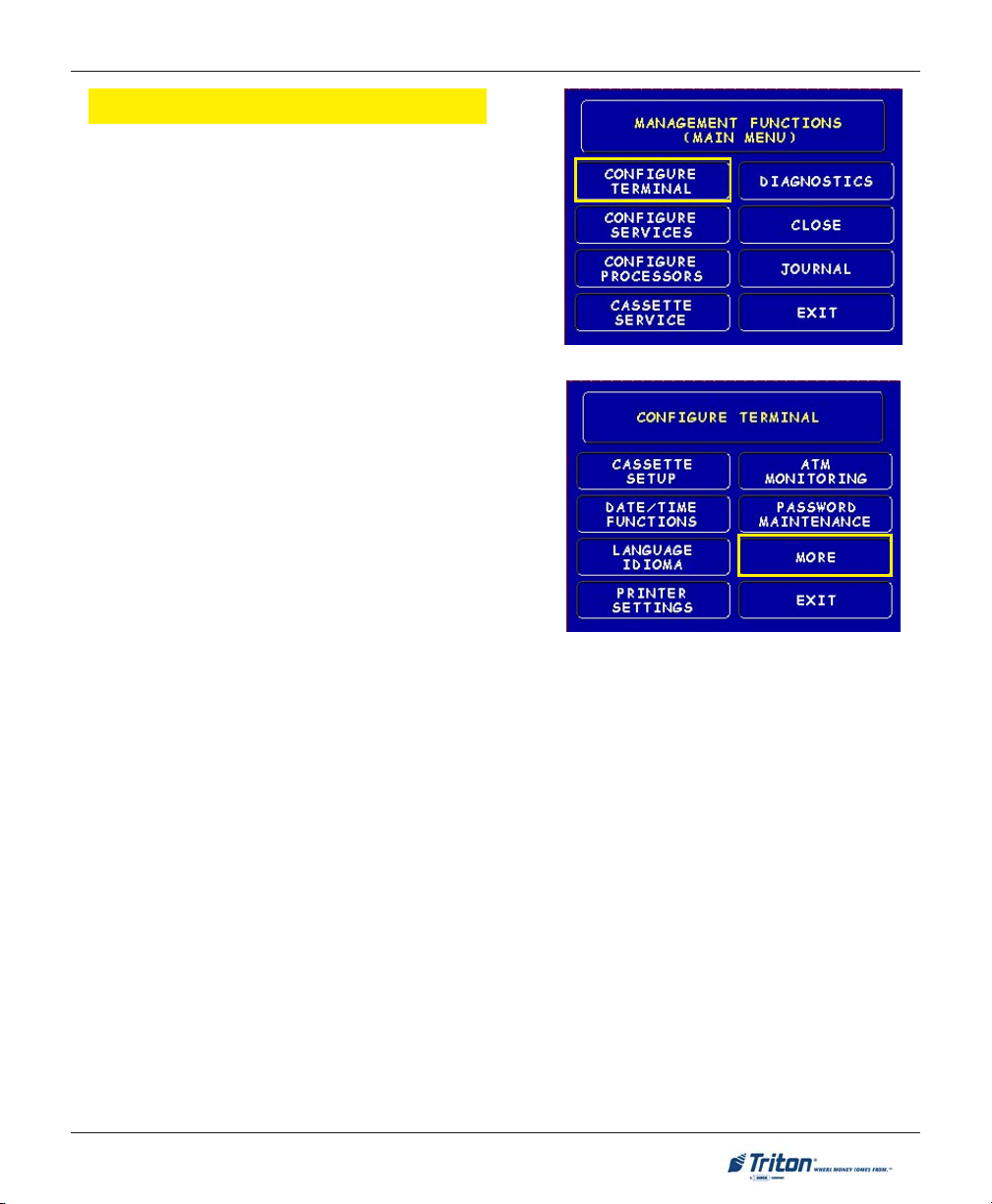
MANAGEMENT FUNCTIONS
CONFIGURE TERMINAL
ACCESS INSTRUCTIONS:
1. From the MAIN MENU screen, select CONFIGURE T ER-
MINAL.
DESCRIPTION:
The following options will be available from the CONFIGURE
TERMINAL screen:
1. Cassette Setup. Allows the terminal operator to view
and change cassette parameters.
2. Date/Time Functions. Provides a menu related to
configuration of date and time parameters
3. Language Idioma. Provides access to the options
that control the language that is displayed on the
ATMs LCD display.
4. Printer Settings. Provides access to printer receipt
length, low paper acknowledgment, and graphics.
5. ATM Monitoring. Allows Triton Connect™ setup and enabling, heartbeat messaging, and alarm
thresholds.
6. Password Maintenance. Allows access to menus for viewing and changing the Master and Admin-
istrative passwords.
7. More. Additional options for couponing, messaging, etc. A listing of items are covered on the next
page.
19
Page 28
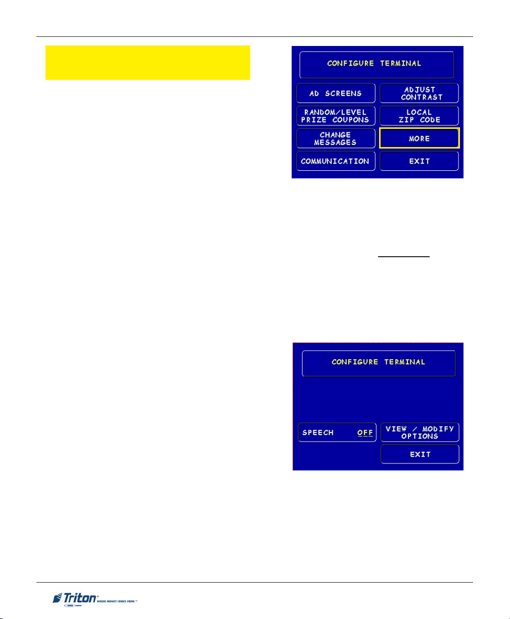
MODEL 9100 USER MANUAL
CONFIGURE TERMINAL
(MORE)
1. AD Screens. This feature enables or disables the
display on an idle terminal to alternate between the
Welcome Screen and a screen containing graphics
and text elements used to make an advertisement
screen.
2. Random/Level Prize Coupons. Provides access to
setup terminal operations for issuing printed and dispensed prize coupons.
3. Change Messages. Allows information for various terminal and receipt messages to be changed
or authored.
4. Communication. Allows modem and/or TCP/IP parameters to be configured and tested.
5. Adjust Contrast. Adjusts the contrast of the display. *Note: This function not available in Model
8100/9100 ATMs. A manual adjust is located on the units Main board.
6. Local Zip Code. Allows entry of the zip code where terminal is located.
7. More. Two (2) more additional options; Speech and View/Modify.
1. Speech On/Off. Enables/disables the voice-acti-
vated headphone jack.
2. View/Modify Options. Allows access for setting a
selected feature.
20
Page 29
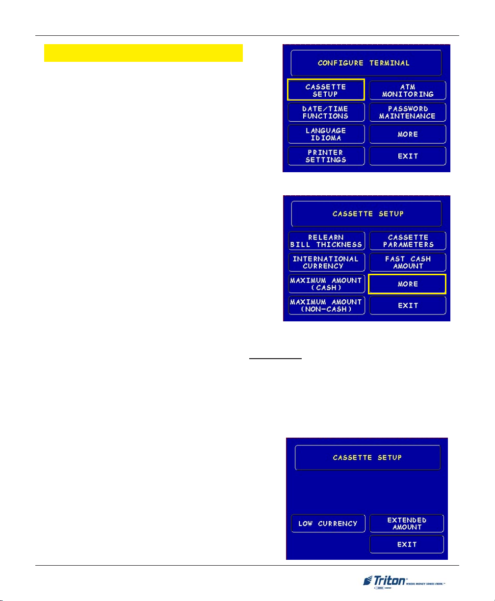
MANAGEMENT FUNCTIONS
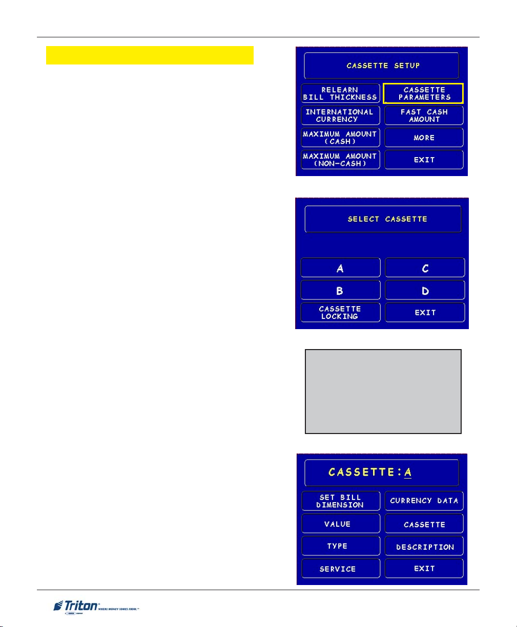
CASSETTE SETUP
ACCESS INSTRUCTIONS:
1. From the MAIN MENU screen, select CONFIGURE T ER-
MINAL.
2. From the CONFIGURE TERMINAL screen, select CAS-
SETTE SETUP.
DESCRIPTION:
The following options will be available from the CASSETTE
SETUP screen:
1. Relearn Bill Thickness. Enables you to force the
dispenser to enter the learning mode (TDM-family
dispensers).
2. International Currency. Allows operator to select
one of (128) pre-defined characters as possible monetary symbols that describe the type of currency
being used.
3. Maximum Amount (Cash). Allows operator to set
the maximum amount withdrawal limit. The maximum
amount cannot be more than fifty (50) times the denomination value in the cash dispenser.
4. Maximum Amount (Non-Cash). Allows operator to set maximum non-cash purchase limit for noncash items. * Note: This function applies to NMD-family dispensers only!
5. Cassette Parameters. Used to perform cassette-specific configuration and setup operations.
6. Fast Cash Amounts. These amounts are entered by operator to prompt customer to select five (5)
convenient amounts. The amounts must be multiples of the denomination(s) in the cassette(s).
7. More: Two (2) more additional options; Low Currency and Extended Amounts.
1. Low Currency. Used to enable/disable low currency
checking on the dispenser mechanism. *Note: Avail-
able with units that have an SDD 1700 dispenser
mechanism installed.
2. Extended Amount. Extends the currency amount entry field from eight (8) to twelve (12) digits, if needed.
21
Page 30
MODEL 9100 USER MANUAL
CASSETTE PARAMETERS
ACCESS INSTRUCTIONS:
1. From the CONFIGURE TERMINAL screen, select CAS-
SETTE SETUP.
2. From the CASSETTE SETUP screen, select CASSETTE
PARAMETERS.
3. Select CASSETTE “A”, “B”, OR “C” (cassette “D”
will be grayed out).
DESCRIPTION:
The following options will be available from the CASSETTE
SETUP screen:
1. Set Bill Dimensions. Note: Does not apply for TDM
dispensers.
2. Value. Allows the operator to set the value of a cash
or non-cash item in a particular cassette. Value is the
denomination of the currency or face value of the
particular non-cash item.
3. Type. This describes the item in the particular cas-
sette: “Cash” or “Non-Cash”. Default is “Cash”.
4. Service. This function displays the current cassettes
status and provides the option to place a cassette
either IN SERVICE or OUT OF SERVICE.
Note: Multi-cassette TDM dispensers only.
5. Currency Data. Note: Does not apply for TDM
dispensers.
6. Cassette. Allows you to select another cassette, if
applicable.
7. Description. Provides access to menus that let the
operator enter a brief description of non-cash only
items in a cassette (Applies to NMD-family dispens-
ers only!).
22
*Note*
!!
! Cassette “A” is for single
!!
cassette dispensers.
!!
! “CASSETTE LOCKING” feature
!!
does not apply.
Page 31

MANAGEMENT FUNCTIONS
CONFIGURE PROCESSORS
ACCESS INSTRUCTIONS:
1. From the MAIN MENU screen, select CONFIGURE PRO-
CESSORS.
2. From the CONFIGURE PROCESSORS screen, select option (1).
** Important**
Option (1) MUST be configured. It is the default
processor for standard ATM transactions.
DESCRIPTION:
The following options will be available from the CONFIGURE
PROCESSORS screen:
0. Processor Name.
1. Terminal ID.
2. Key Management.
3. Communication Type.
4. Communication Numbers.
5. Send Terminal Totals.
6. Status Monitoring.
7. EOT (End Of Transmission).
8. Communications Header.
9. Predial.
23
Page 32

MODEL 9100 USER MANUAL
CONFIGURE PROCESSORS
Option 0. Processor Name
Processor Name. Allows entry for the name of the
specified processor (Ex: CALYPSO)
Option 1. Terminal ID
Option 3. Communication Type
Communication Type. Allows user to toggle be-
tween the communication type the terminal is using
(Dial-up,TCP/IP). Note: Models 8100/9100 auto
detect the communication type installed and will
not allow user to change (toggle).
Option 4. Communication Numbers
Terminal ID. Allows entry of the terminal ID as-
signed by the host processor.
Option 2. Key Management
Key Management. Allows entry of the PIN Master
key(s) assigned by the host processor.
Communication Numbers. Allows entry of the host
processors primary and backup (if needed) phone
numbers or the Host TCP/IP/ addresses if running
that communication type.
24
Page 33

MANAGEMENT FUNCTIONS
CONFIGURE PROCESSORS
The remaining options are toggled to either ‘Enable’ or ‘Disable’ that particular function.
Send Terminal Totals. When this option is En-
abled, the terminal will send accumulated totals information to the processor during the close operation.
Status Monitoring. Status monitoring is a feature
available with selected processor software. When
Enabled, the terminal will send operational status
information to the processor. The status information is sent in a data field that is part of any of the
following messages:
! A transaction request message.
! Comms key download.
! Host totals download request.
! Reversal request message.
EOT (End Of Transmission). When this option is
Disabled, the terminal will not look for the EOT
character at the conclusion of the transaction. Contact your host processor to verify before Enabling.
This option is processor-specific.
Options 5-9. Toggled (Enable/Disable)
Communications Header. This optional feature is
only applicable to certain processors. When required, it must be Enabled and have the correct data
in the header data field. The Communication Header
consists of alphanumeric characters.
Predial. When this feature is Enabled, the terminal
will dial out to the processor and establish a connection as soon as the customer’s ATM or credit
card has been scanned by the card reader.
**Warning**
Enabling the COMMUNICATION
HEADER when using a processor that
doesn’t use this feature will prevent any
type of transaction from completing. Disabling or having incorrect data in the
COMMUNICATION HEADER data field
(if the feature is required) will also prevent
any type of transaction from processing
25
Page 34

MODEL 9100 USER MANUAL
KEY MANAGEMENT
ACCESS INSTRUCTIONS:
1. From the MAIN MENU screen, select CONFIGURE PRO-
CESSORS.
2. From the CONFIGURE PROCESSORS screen, select option
(2) for KEY MANAGEMENT.
DESCRIPTION:
The KEY MANAGEMENT function provides access to the ATMs functions that control the method of entry
for MAC Master Keys and/or PIN Master Keys, downloading the PIN Working Keys, and displaying the
Check Digits. The new VEPP requires that two key parts for each key are loaded. After this screen will be
a screen to indicate that the second part must be entered. Then the “Enter” function key will be displayed
to load the second key part. After the second key part is loaded, the terminal will prompt if any additional
key parts need to be loaded.
* Important*
Before proceeding, check to ensure there are no VEPP Tamper (EC 205) or
VEPP Serial Number (EC 239) errors. You must clear these errors first!. To
check/clear the errors, enter MANAGEMENT FUNCTIONS > DIAGNOSTICS > MORE
DIAGNOSTICS > MORE (MORE) DIAGNOSTICS > KEYPAD. Failure to clear these
errors first will decline entry of DES keys.
The following sequence will be displayed from the KEY MANAGEMENT screen:
1. Enter Master Keys - Select this option to
enter the encryption keys.
Download Working Keys - Select this option
to download the Working Keys (Must be selected after entering PIN and/or MAC Master keys).
Check Digits - Displays encryption key
check digits.
26
Page 35

MANAGEMENT FUNCTIONS
2. Password Required - When “Enter Master Keys” is
selected, you will be prompted to enter two (2) passwords. If this is an initial setup, the default password
is six (6) zeros (000000) for each. You will then be
prompted to change passwords. Passwords MUST
be changed!
3. Change Password (Initial Setup) - The VEPP requires
that no default password can be entered. If a user
enters the default password, the VEPP will force the
user to change them before they can enter keys.
4. Change User Passwords (cont) - This screen allows
the user(s) to select which password to change. If
any password is the default value, the VEPP will only
allow these two functions to be selected.
5. Change User Passwords (cont) - If this is an initial
setup, the current password will be six (6) zeros
(000000). Enter a new password (twice). A password
consists of six (6) numbers, no characters. A screen
prompt will appear if the passwords was changed
successfully. DO NOT use weak passwords (Ex:
111111,123456)
27
Page 36

MODEL 9100 USER MANUAL
6. Enter Master Keys - This screen allows selection to
enter the Master keys. You MUST enter PIN Master
keys. DO NOT enter keys in the MAC Master keys
unless processor directs. You MUST enter two (2)
sets of keys (32 alpha/numerical).
7. Enter Keys - Enter the first (32) alpha/numerical key.
The on-screen keypad legend describes the ATMs
keypad for entering numbers and characters. Select
“ENTER” using the display function key.
8. Check Digits - After selecting “Enter” from previous screen, you will get the Check Digit which you
can either Accept or Decline. When you “Accept”
the key check digit, enter the second key. After accepting the second key part, you will be prompted
“Another Key Part”. Select “Yes” if a third key is
needed or “No” if none.
9. Download Working Keys - After entering the keys,
exit out to the Key Management Main screen and
Download Working Keys. You MUST download the
Working keys from the processor.
28
Page 37

MANAGEMENT FUNCTIONS
CONFIGURE SERVICES
ACCESS INSTRUCTIONS:
1. From the MAIN MENU screen, select CONFIGURE SER-
VICES.
DESCRIPTION:
The following options will be available from the CONFIGURE
SERVICES screen:
1. STD ATM Configuration. This option allows con-
figuration of the types of services for normal customer transactions.
2. PaySpot Configuration. This option allows configu-
ration of cellular and long-distance services.
(NO LONGER SUPPORTED)
3. CashWorks Configuration. This option allows con-
figuration of maximum check cashing amounts.
(NO LONGER SUPPORTED)
4. Western Union Configuration. This option allows
configuration of note denominations loaded in the
dispenser mechanism and account types.
(NO LONGER SUPPORTED)
*Note*
STD ATM Configuration uses the
default processor number one (1).
You MUST configure processor
number (1) for standard terminal
operations.
29
Page 38

MODEL 9100 USER MANUAL
STD ATM CONFIGURATION
ACCESS INSTRUCTIONS:
1. From the MAIN MENU screen, select CONFIGURE SER-
VICES.
2. From the CONFIGURE SERVICES screen, select STD.
ATM CONFIGURATION.
DESCRIPTION:
The following options will be available from the STA N-
DARD ATM CONFIGURATION screen:
1. Transaction Types. This function allows turning
ON or OFF the availability of two (2) transaction
types: Transfers and Balance Inquiries. It also
allows prompting the customer on balance inquiries.
2. Account Types. Allows turning ON or OFF the
availability of two (2) account types: Savings and
Credit Card.
3. Surcharge. This function allows operator to set
surcharging configurations.
30
*Note*
The Using Processor defaults to
processor number one (1) in the
Configure Processor setup. You can
not change the processor.
Page 39

MANAGEMENT FUNCTIONS
CASSETTE SERVICE
ACCESS INSTRUCTIONS:
1. From the MAIN MENU screen, select CASSETTE SER-
VICE.
DESCRIPTION:
The CASSETTE SERVICE function allows the operator to
put the selected cassette(s) “In Service” or “Out of
Service”. This function can also be used to clear Error
Code 156, Cassette Out of Service.
Note: For single cassette dispensers, cassette “A” is automatically “In Service”.
31
Page 40

MODEL 9100 USER MANUAL
DIAGNOSTICS
ACCESS INSTRUCTIONS:
1. From the MAIN MENU screen, select DIAGNOSTICS.
DESCRIPTION:
The following options will be available from the DIAGNOS-
TICS screen:
1. Status. This function presents the status checks on
the primary functional areas of the dispensing
mechanism.
2. Purge. This function instructs the dispenser to remove all documents from the feed path. The return
code for a successful purge in a single cassette dispenser is ‘20 20 20’. The return code for a multi-cassette dispenser is ‘0’.
3. Test Dispense. This function instructs the dispens-
ing mechanism to dispense one (1) note from the
cassette into the reject cassette/compartment.
(TDM installed) A return code in a single cassette
dispenser of ‘20 1 0 0 0’ indicates a successful test
dispense (20) and (1) note picked from cassette A.
(SDD/Minimech) A return code in a single cassette
dispenser of ‘20 20 21’ indicates a successful test
dispense (20) and (1) note picked from the cassette.
4. Format Graphic Memory. This function erases the memory used to store AD graphics. AD graphics can then be downloaded from a local terminal or through Triton Connect.
5. Test Receipt Printer. This function tests the operation of the receipt printer and prints out con-
figuration parameters, processor setup, etc, that may be used to verify terminal setup.
6. Version #’s. This function displays the version numbers of the terminal operating software.
7. More Diagnostics. Accesses additional diagnostic functions.
32
Page 41

MANAGEMENT FUNCTIONS
MORE DIAGNOSTICS
ACCESS INSTRUCTIONS:
1. From the MAIN MENU screen, select DIAGNOSTICS.
2. From the DIAGNOSTICS screen, select MORE DIAG-
NOSTICS.
DESCRIPTION:
The MORE DIAGNOSTICS menu allows the terminal operator
to perform the following functions:
1. Inject New Cassette ID. This function enables the
user to change the identification code of a cassette.
*Note: For NMD multi-cassette dispensers only.
2. Communication. This function performs a function
test of the modem or TCP/IP hardware. This does
not test the ability of the modem or TCP/IP device to
communicate with the phone/data line.
3. MODEM SPEAKER ON/OFF. Allows speaker sound on
or off.
4. FORCE UNLOCK. This function provides a means of
overriding the unlocking mechanism associated with
a particular cassette. It is to be used immediately
after failure of a normal cassette unlock operation.
*Note: For NMD multi-cassette dispensers only.
5. PRINT DISPENSER STATUS. This function prints the “TDM Status” report. This report provides
useful information that can assist a service technician. *Note: Available when a TDM dispensing
mechanism is installed.
6. CLEAR DISPENSER STATUS. This function resets the count in the “Since Reset” column on the
dispenser data report.
*Note: Available when a TDM dispensing mechanism is installed.
7. MORE DIAGNOSTICS. Accesses additional diagnostic functions.
8. PREVIOUS. Returns user to main diagnostics screen.
33
Page 42

MODEL 9100 USER MANUAL
MORE (MORE) DIAGNOSTICS
ACCESS INSTRUCTIONS:
1. From the MAIN MENU screen, select DIAGNOSTICS.
2. From the DIAGNOSTICS screen, select MORE DIAG-
NOSTICS, then select MORE DIAGNOSTICS again.
DESCRIPTION:
The MORE (MORE) DIAGNOSTICS menu allows the terminal
operator to perform the following functions:
Note: VEPP errors MUST be cleared before attempting to
enter Master keys.
1. Keypad. This function enables the user to reset VEPP
errors that appear on the terminal screen (Error Code
(EC) 205 and/or 239). It also provides a status of the
VEPP device which can be printed.
!!
! Clear Tamper. Allows user to reset a tamper
!!
condition if exists (EC-205).
!!
! Clear Serial Tamper. Allows user to reset a serial
!!
number tamper condition if exists (EC-239).
!!
! Status. Allows user to view/print the VEPP device
!!
status.
2. Scan Card. Enables testing an ATM or credit card
for proper operation in the terminal card reader.
Key Status A-D refers to multi-host processors key
information.
SUTATSYEK
00dedaoLsyeKoN
20dedaoLyeKretsaMNIP
30dedaoLsyeKretsaMCAM/retsaMNIP
41
63
WNIP
dedaoLyeKretsaMNIP
dedaolnwoDyeKgnikro
dedaoLsyeKretsaMCAM/retsaMNIP
dedaolnwoDsyeKgnikroWCAM/gnikroWNIP
34
Page 43

MANAGEMENT FUNCTIONS
CLOSE
ACCESS INSTRUCTIONS:
1. From the MAIN MENU screen, select CLOSE.
DESCRIPTION:
The following options will be available from the CLOSE
screen:
1. Schedule Close. This function allows you to turn
ON/OFF the schedule close feature. It also provides
access to specify the time of day when a DAY CLOSE
process is initiated.
2. Trial Close. This function is used to get the totals
from the ATM. It prints information from the processor and the terminal itself. It functions like a Day
Close except the totals are not cleared.
3. Day Close. This function is used to complete daily
balancing of the ATM with the processor. The printed
information includes a total of all transactions. The
totals are cleared and switched to the next business
day.
4. Trial Cassette Close (All). This function prints a
receipt summarizing activity on all cassettes since
the last Cassette Close was performed. The totals
are not cleared or reported to the processor.
5. Cassette Close. This function is used to access menu
options for cassette close and replenishment actions.
35
Page 44

MODEL 9100 USER MANUAL
CASSETTE CLOSE
ACCESS INSTRUCTIONS:
1. From the MAIN MENU screen, select CLOSE.
2. From the CLOSE screen, select CASSETTE CLOSE.
DESCRIPTION:
The following options will be available from the CASSETTE
CLOSE screen:
Select Cassette. This option allows the operator to select
cassette-specific close operations. Note: Single cassette
dispensers default to cassette “A”.
1. Trial Cassette Close. Prints a receipt summarizing
activity on the selected cassette since the last Cassette Close was performed (Totals are not cleared or
reported to the host).
2. Cassette Close. This function is used to complete
the balancing of the specified cassette. It prints a
report summarizing all activity on the selected cassette since the last Cassette Close and clears the
totals. It also resets the number of bills in the cassette to zero (0).
3. Select Cassette. Allows operator to switch between
cassettes when performing cassette close operations.
Note: Cassette “D” will be grayed out.
4. Enter Qty. in Cassette. This option allows entry of
the number of notes/documents in the cassette. This
number is used as the starting point for the cassette
close report.
*Note: Enter the total number of notes placed in
the cassette, NOT the value of the currency.
36
Page 45

MANAGEMENT FUNCTIONS
JOURNAL
ACCESS INSTRUCTIONS:
1. From the MAIN MENU screen, select JOURNAL.
DESCRIPTION:
The following options will be available from the JOURNAL
screen:
1. Print Journal. This function is used to automatically print out any journal entries collected since the
last time the journal was printed. All unaudited
records are printed and marked as audited.
2. Clear Journal. This function is used to mark all
unprinted records as audited. They will not be printed
out when a Print Journal command is performed.
3. Print Last X Entries. This function is used to retrieve audited and unaudited records from the jour-
nal, either before or after they have been Printed or
Cleared.
*Note*
The Electronic Journals (EJ) buffer can store up to 2045 entries. If you have
an external EJ (units with an SDD or Minimech dispenser), you may retrieve
the last 2045 entries using the Print Last X command.
The TDM dispenser mechanisms installed have an imbedded memory chip
that holds the journal entries. You may retrieve the last 1024 entries using
the Print Last X command.
37
Page 46

MODEL 9100 USER MANUAL
THIS PAGE INTENTIONALLY LEFT BLANK
38
Page 47

MANAGEMENT FUNCTIONS
TCP/IP (ETHERNET)
CONFIGURATION
39
Page 48

MODEL 9100 USER MANUAL
INTRODUCTION
(TCP/IP ETHERNET)
This section will discuss the TCP/IP Ethernet-specific Management Functions. The Ethernet hardware
should be previously installed. In the 8100/9100 models, only one communication type is allowed for all
hosts.
TCP/IP A
The Ethernet-equipped ATM communicates using Transmission Control Protocol (TCP) and Internet
Protocol (IP), allowing it to send and receive information in the form of small packets of digital data. In
order to configure the ATM to correctly access the host network using this protocol, IP addresses must
be entered into the appropriate ATM setup functions. The Addresses are the HOST TCP/IP, TERMINAL IP,
SUBNET MASK, GATEWAY, and LISTENING PORT.
The addresses are attached to the data packet that is being sent; the HOST TCP/IP address allows the
data packet to be routed through the TCP/IP Ethernet network, ultimately to be received and processed
by the host server on the network. The TERMINAL IP address identifies the ATM as the source of the data
packet, and is used by the host server to return acknowledgements, transaction approvals, or other data
to the ATM. Alongside the addresses, each port requires a SUBNET MASK.
This part of the IP address distinguishes other machines on the same LAN from machines in other
departments or elsewhere in the world. For direct access to networks beyond the current one, each
machine must be told the IP addresses of the router (or GATEWAY) that connects the local network with the
wider world. The LISTENING PORT value identifies the data being sent to that specific machine. The MAC
ADDRESS is assigned from the iChip manufacturer. The CHIP VERSION indicates the chip family, software
version, and boot block revision in the Ethernet device only. TCP/IP TIMEOUT is the time that the terminal
will wait from the message to be sent to the host and the time it takes for the host to respond.
If Triton Connect ATM monitoring software is being used, the applicable IP addresses for the Triton
Connect host computer and Alarm Monitoring feature must also be entered.
DDRESSES
The descriptions on the following pages will cover how to access the appropriate functions and initially
enter the IP addresses and any other TCP/IP Ethernet operating parameters or diagnostics.
40
Page 49

MANAGEMENT FUNCTIONS
CONFIGURE PROCESSORS
COMMUNICATION TYPE
ACCESS INSTRUCTIONS:
1. From the MAIN MENU screen, select CONFIGURE PRO-
CESSORS.
2. From the CONFIGURE PROCESSORS screen, select option (1).
3. From the CONFIGURATION FOR: menu screen, select
option (3).
** Important**
Option (1) MUST be configured. It
is the default processor for standard
ATM transactions.
DESCRIPTION:
The COMMUNICATION Type function allows user to toggle
between the communication type the terminal is using. You
can select either Dialup, Wireless, or TCP/IP. The External
Ethernet option must be installed to select.
Note: (Model 8100/9100 ATMs)
This function detects the
communication type installed and
WILL NOT allow user to change
(toggle). It also sets the
communication type for Triton
Connect
41
Page 50

MODEL 9100 USER MANUAL
COMMUNICATION NUMBERS
ACCESS INSTRUCTIONS:
1. From the MAIN MENU screen, select CONFIGURE
PROCESSORS.
2. From the CONFIGURE PROCESSORS screen, select
option (1).
3. From the CONFIGURATION FOR: menu screen, select
option (4).
DESCRIPTION:
The COMMUNICATION Numbers function allows entry of the host processors primary and backup (if
needed) phone numbers or the Host TCP/IP Addresses if running TCP/IP communications type.
The HOST TCP/IP ADDRESSES are provided by your host Network Administrator . The first part of the
address consists of a sequence of four groups of numbers. Each group can be up to three digits long, and
each group is separated by a period (dot character), as in this example: 123.3.01.99 The second part of
the address is a PORT NUMBER, consisting of five (5) digits or less, separated from the first part by a
comma (‘,’) character, as in this example: 123.3.01.99,23353.
Follow these steps to initially enter or change the PRIMARY HOST TCP/IP ADDRESS:
! Select which host address you want to enter/change (Primary/Backup).
! Enter the first group of numbers in the IP Address using the main keypad keys.
! Enter a ‘dot’ character by pressing the <Control> key, then the <0> key Twice to select the period’,
then the <Right Arrow> key to lock it in.
! Repeat Steps 2 and 3 for the second and third group of numbers in the IP Address.
! Enter the fourth group of numbers in the IP Address.
! Enter the comma (“,”) character by pressing the <Control> key, then the <0> key Once to select the
comma. Press the <Right Arrow> key to lock it in.
! Enter the PORT NUMBER. Select <Enter> to save the Host /IP Address entry, or <Cancel> to discard
the changes. Repeat steps for BACKUP HOST TCP/IP ADDRESS entry.
42
Page 51

MANAGEMENT FUNCTIONS
CONFIGURE TERMINAL
TCP/IP CONFIGURATION
ACCESS INSTRUCTIONS:
1. From the MAIN MENU screen, select CONFIGURE T ER-
MINAL.
2. From the CONFIGURE TERMINAL screen, select MORE.
3. From the MORE screen, select COMMUNICATION.
4. From the COMMUNICATION screen, select TCP/IP CON-
FIGURATION.
DESCRIPTION:
The TCP/IP CONFIGURATION option allows access to setup
parameters that control communication between the ATM
and the Host Network. It also allows testing of the External
Ethernet device.
The following parameters are accessed through this function
and described on the following pages:
!!
! NETWORK S ETTINGS
!!
!!
! TEST TCP/IP
!!
43
Page 52

MODEL 9100 USER MANUAL
NETWORK SETTINGS
Description:
The NETWORK SETTINGS parameters are provided by your
host Network Administrator. The TERMINAL IP ADDRESS,
SUBNET MASK, and GATEWAY A DDRESS consist of a sequence
of four groups of numbers. Each group can be up to three
digits long and each group is separated by a period (dot
character), as in this example: 123.3.01.99
Follow these steps to initially enter or change the TERMINAL
IP ADDRESS, SUBNET MASK, and GAT EWAY A DDRESS:
! Select <Change> to blank the current entry, if necessary.
! Enter the first group of numbers in the Address/Value
using the main keypad keys.
! Enter a ‘dot’ character by pressing the <Control> key,
then the <0> key Twice to select the period’, then the
<Right Arrow> key to lock it in.
! Repeat Steps 2 and 3 for the second and third group of
numbers for the Address/Value.
! Enter the fourth group of numbers for the Address/
Value.
! Select <Enter> to save the Address/Value entry or
<Cancel> to discard the changes.
44
Page 53

MANAGEMENT FUNCTIONS
NETWORK SETTINGS
The CHIP VERSION and MAC ADDRESS are reference
parameters ONLY - no configuring is done. The Chip Version
is the software version running on the ATM and the MAC
Address is hard-coded from the Ethernet device.
The TCP/IP TIMEOUT is defaulted to 120 seconds, but may
be increased or decreased depending on response time.
Maximum timeout value is 999 seconds.
The LISTENING PORT value consists of five (5) digits or
less.
Follow the steps below to initially enter or change the
LISTENING PORT:
! Select <Change> to blank the current entry, if
necessary.
! Enter the LISTENING PORT number. Select <Enter> to
save the Port Entry or <Cancel> to discard the
changes.
45
Page 54

MODEL 9100 USER MANUAL
TEST TCP/IP
DESCRIPTION:
This option allows testing of the TCP/IP device. When
selected, the Ethernet PCB assembly initializes and resets
the configuration hardware imbedded in the device. If test
is successful, a “Tested OK” will be displayed.
ERROR CONDITION:
If the test fails, an error message will be displayed. Check
the cable connections from the External Ethernet device to
the Main board. Possible problems could be no or incorrect
voltage to unit, IF/Host cable, Main board, or Ethernet PCB
assembly.
Error Code 237 may appear during
operation. This code means there is
a TCP/IP failure.
46
Page 55

MANAGEMENT FUNCTIONS
TRITON CONNECT
TCP/IP CONFIGURATION
ACCESS INSTRUCTIONS:
1. From the MAIN MENU screen, select CONFIGURE T ER-
MINAL.
2. From the CONFIGURE TERMINAL screen, select ATM
MONITORING.
3. From the ATM MONITORING screen, select TRITON
CONNECT.
4. From the TRITON CONNECT screen, select TCP/IP
CONFIGURATION.
** Important **
If using, turn Triton Connect <ON>
after entering the Configuration
parameters.
DESCRIPTION:
The TRITON CONNECT function allows
the terminal operator to set up parameters that control DIAL-
UP and TCP/IP communications between the ATM and
Triton Connect PC-based software to remotely manage your
Triton Systems ATMs. The following TCP/IP parameters
are accessed through this function and described on the
following pages:
!!
! Host Numbers
!!
!!
! Alarm Numbers
!!
!!
! TCP/IP Configuration
!!
Note: Comms Type Option
You must have the External Ethernet device
installed. For Model 8100/9100 ATMs, this function
detects the communication type installed (Dialup
or TCP/IP) and will not allow user to change
(toggle).
47
Page 56

MODEL 9100 USER MANUAL
TRITON CONNECT
HOST NUMBERS
DESCRIPTION:
The HOST NUMBERS are provided by your Processor/Host
Network administrator. If you are using TCP/IP as your
communication type, you will need to enter HOST TCP/IP
ADDRESSES. The first part of the address consists of a
sequence of four groups of numbers. Each group can be
up to three digits long, and each group is separated by a
period (dot character), as in this example: 123.3.01.99 The
second part of the address is a PORT NUMBER, consisting
of four (4) digits or less, separated from the first part by a
comma (“,”) character, as in this example:
123.3.01.99,9043.
Follow these steps to initially enter or change the PRIMARY
HOST NUMBER (ADDRESS):
! Select <Change> to blank the current entry, if necessary.
! Enter the first group of numbers in the TCP/IP Address
using the main keypad keys.
! Enter a ‘dot’ character by pressing the <Control> key,
then the <0> key Twice to select the period’, then the
<Right Arrow>key to lock it in.
! Repeat Steps 2 and 3 for the second and third group of
numbers in the TCP/IP Address.
! Enter the fourth group of numbers in the TCP/IP
Address.
! Enter the comma (“,”) character by pressing the
<Control> key, then the <0> key Once to select the
comma. Press the <Right Arrow> key to lock it in.
! Enter the PORT NUMBER. Select <Enter> to save the
Primary TCP/IP Address entry or <Cancel> to discard
the changes. Repeat steps for BACKUP HOST NUMBER
(ADDRESS) entry.
48
Page 57

MANAGEMENT FUNCTIONS
TRITON CONNECT
ALARM NUMBERS
DESCRIPTION:
The ALARM NUMBERS are provided by your Processor/
Host Network Administrator. If you are using TCP/IP as
your communication type, you will need to enter ALARM
TCP/IP ADDRESSES. The first part of the address consists
of a sequence of four groups of numbers. Each group can
be up to three digits long, and each group is separated by
a period (dot character), as in this example: 123.3.01.99
The second part of the address is a Port Number, consisting
of four (4) digits or less, separated from the first part by a
comma (“,”) character, as in this example:
123.3.01.99,9043.
Follow these steps to initially enter or change the PRIMARY
ALARM NUMBER (ADDRESS):
! Select <Change> to blank the current entry, if necessary.
! Enter the first group of numbers in the TCP/IP Address
using the main keypad keys.
! Enter a ‘dot’ character by pressing the <Control> key,
then the <0> key Twice to select the period’, then the
<Right Arrow> key to lock it in.
! Repeat Steps 2 and 3 for the second and third group of
numbers in the TCP/IP Address.
! Enter the fourth group of numbers in the TCP/IP
Address.
! Enter the comma (“,”) character by pressing the
<Control> key, then the <0> key Once to select the
comma. Press the <Right Arrow> key to lock it in.
! Enter the PORT NUMBER. Select <Enter> to save the
Primary Alarm TCP/IP Address entry or <Cancel> to
discard the changes. Repeat steps for BACKUP ALARM
NUMBER (ADDRESS) entry.
49
Page 58

MODEL 9100 USER MANUAL
TRITON CONNECT
TCP/IP CONFIGURATION
DESCRIPTION:
The TERMINAL IP and LISTENING PORT
ADDRESSES are provided by your Host Network
Administrator. The Terminal Address consists of a sequence
of four groups of numbers. Each group can be up to three
digits long, and each group is separated by a period (dot
character), as in this example: 123.3.01.99
The Listening Port value consists of five (5) digits or less.
Follow these steps to initially enter or change the TERMINAL
IP ADDRESS and LISTENING PORT values:
! (TERMINAL IP ADDRESS) Select <Change> to blank the
current entry, if necessary.
! Enter the first group of numbers in the IP Address using
the main keypad keys.
! Enter a ‘dot’ character by pressing the <Control> key,
then the <0> key Twice to select the period’, then the
<Right Arrow> key to lock it in.
! Repeat Steps 2 and 3 for the second and third group of
numbers in the IP Address.
! Enter the fourth group of numbers in the IP Address.
Select <Enter>.
to save the Terminal IP Address entry or <Cancel> to
discard the changes.
! (LISTENING PORT) Select <Change> to blank the current
entry, if necessary.
! Enter the Listening Port number. Select <Enter> to
save the Port Address entry or <Cancel> to discard the
changes.
50
Page 59

SECTION 4
CASSETTE CLOSE
CASH REPLENISHMENT
51
Page 60

MODEL 9100 USER MANUAL
INTRODUCTION
The purpose of this section of the manual is to describe the procedures for cassette closing and replenishment. Information concerning note handling and quality issues are explained initially.
DISPENSING MECHANISMS
The Model 9100 ATM can accomodate most dispensing mechanisms in the TDM family (100/150/200/
250). In addition, an SDD and MiniMech (Mech-10) dispenser are also available.
Currency capacity depends upon the dispenser mechanism installed in the ATM, but is also affected by
note quality and thickness. Typical capacities are provided in the following table:
SMSINAHCEMGNISNEPSID0019
RESNEPSIDETTESSAC
001-MDTelgniSsetoN056
051-MDTelgniSsetoN0031
002-MDTelpitluM)ettess
052-MDTelpitluM)ettessacrep(setoN0031
hceMiniMelgniSsetoN057
DDSelgniSsetoN0081
DEDNEMMOCER
YTICAPACMUMIXAM
acrep(setoN056
The dispensing mechanism delivers the appropriate number of notes from the note cassette to fulfill the
customer’s withdrawal request. The purpose of the reject area or cassette is to accept and hold notes that
have been transferred from the note cassette but not dispensed. Some situations that could cause the
mechanism to reject notes are: (1) multiple notes stuck together and (2) note width too short or long.
Other conditions that could cause a reject are described in the next section, Note Condition.
NOTE CONDITION
If possible, store currency at room temperature for at least eight hours before dispensing from the
cassettes.
The number of rejects can be directly influenced by the technique used to load the cassettes and the
quality of the currency. Notes loaded into the cassettes must be in “fit” condition if a high level of
performance (low reject and failure rate) is expected from the unit. “Fit” notes do not possess any of the
defects listed:
**WARNING**
DO NOT RECYCLE REJECTED NOTES INTO A CASSETTE!
Doing so could cause more rejects and/or currency jams.
52
Page 61

CURRENCY HANDLING
USED NOTE DEFECTS
• Adhesive or “sticky” substances on the surface of the paper.
• Tears extending more than 1/2” from the edge of the currency.
• Tears, holes, or missing sections in the body of the currency.
• Tape on the surface of the currency used for repairing, patching or any other purpose.
• Staples, pins, or any other foreign body attached to the notes.
• Corner folds of a size greater than 1/2” on either axis.
• Two or more notes joined by any means.
• Excessively crumpled or crinkled.
EW OR UNCIRCULATED NOTE DEFECTS
N
• All the conditions listed for used notes.
• Excessive bowing due to conditions of packing and storing.
• New or uncirculated currency must be “burst” and fully separated prior to loading into cassettes.
PREPARING NOTES
Use the following procedures to prepare notes before inserting them into a note cassette.
PREPARING USED NOTES
• Remove the band around each bundle of notes.
• Remove foreign objects (e.g. pins, paper clips, crumbs, etc.).
• Remove torn or very worn notes.
• Straighten any folded notes.
PREPARING NEW OR UNCIRCULATED NOTES
• Remove the band around each bundle of notes. Separate the notes from each other by:
• Striking the bundle hard against the edge of a table or similar object.
• Flipping through each bundle of notes in both directions at each end.
• Using a Note Counter.
53
Page 62

MODEL 9100 USER MANUAL
CASSETTE CLOSE
This function is used to complete the balancing of the specified cassette(s). It prints a report summarizing
all activity on the selected cassette(s) since the last CASSETTE CLOSE and clears the totals. It also resets
the number of bills in the cassette to zero (0).
*Note*
Single feed channel dispensers such as the TDM-1XX only display cassette A, all other cassettes will appear
grayed out. The cassette type has a default setting of cash. They are automatically placed in service after boot.
The "In-Service" configuration and status items do not apply to single feed channel dispensers.
For the dual feed channel TDM-2XX dispensers, cassettes A through C are available for configuration. Cassette
D is not supported for any of the TDM dispensers and should appear grayed out on all management functions
screens. The terminal immediately flags non-resident cassettes as out of service once the SW returns from
management functions to customer transactions for multi-feed channel mechanisms.
1. Enter MANAGEMENT FUNCTIONS MAIN MENU screen.
2. (The screens below represent a single note cassette) Select CLOSE > CASSETTE CLOSE > SELECT
CASSETTE > C ASSETTE A: CASSETTE CLOSE.
3. After selecting Cassette A: Cassette Close, a report will be printed summarizing all activity since the
last Cassette Close. The number of bills in the cassette will be reset to zero (0).
54
Page 63

CURRENCY HANDLING
REPLENISH CASSETTE
(TDM-100/150/200/250)
1. Unlock and open the security cabinet door.
2. (TDM-150/200/250) Extend the dispenser mounting tray fully as shown below. Note: The TDM-
100 uses a fixed-tray mounting system.
3. To gain access to the cassette(s), rotate the mechanism mounting platform to the “Service” position:
! Locate the spring-loaded locking pin on the underside of the tray.
! Pull the pin down to release the swivel mounting platform.
! Slowly turn the tray clockwise 180° so that the note and reject cassette(s) can be accessed from the
front of the unit.
! Release the locking pin and move the mounting platform back and forth slightly to ensure the pin
snaps back into place, locking the mounting platform into the service position.
Lift up on slide tray locking levers.
4. To remove the note cassette(s), grasp the cassette
handle and pull in a firm but controlled manner to
release the cassette from the snap catches. Try to
use only the minimum amount of force to release
the cassette! The cassette will only move a few
inches! Once released from the snaps, you can
slide the cassette out of the mechanism. Place the
cassette on a level, flat surface for replenishment.
55
Rotate mechanism to “Service” position
(clockwise).
Removing note cassette (TDM-100).
Page 64

MODEL 9100 USER MANUAL
LOADING THE CURRENCY CASSETTE
1. Unlock and open the cassette lid using the supplied key. Move the pusher plate to the rear of the
cassette (toward the handle).
Note: The cassette(s) use a locking mechanism to hold the packer plate in the loading position. Pull the
pusher-plate all the way back to the handle end of the cassette and turn the key to latch the pusher plate
into the loading position.
Unlock and open note cassette.
2. Count the number of bills that remain in the cassette, if any. Next, count the number of bills that are
being added into the cassette.
3. Add the number of bills being placed into the cassette to the number that remained. The “Total”
number of these bills will be entered in the “ENTER QTY . IN CASSETTE” option. Place the currency into
the cassette between the pusher plate and front of cassette.
4. Turn the key to release the catch, allowing the
pusher plate to compress the notes. Hold notes
while allowing plate to move.
5. Close and lock the cassette. Remove the key. Slide
the cassette back into its compartment in the
dispensing mechanism. Make sure the cassette is
fully inserted! You will feel the cassette latch
securely into the snap catches.
Pull the packer plate back. Allow the pusherplate to be latched in position using the key-lock.
56
Page 65

CURRENCY HANDLING
REMOVING THE R EJECT CASSETTE
The reject tray is located just above the currency cassette(s) in the dispensing mechanism. Follow these
steps to remove the reject tray:
1. Slide the reject tray out of its compartment in the dispensing mechanism. Place the tray on a flat
surface.
2. Unlock the tray using the supplied key. Flip the top back to gain access to the reject compartment.
Remove reject cassette. Unlock and open reject cassette.
3. Remove any notes in the reject compartment. Close and lock the reject tray. Remove the key. Slide the
cassette back into its compartment in the dispensing mechanism. Make sure the reject cassette is
fully inserted! You will feel the cassette snap securely into the catches.
Note: You may wish to record the denomination and number of notes removed from the reject tray for
use when balancing the note tray against the cassette/day close records.
**WARNING**
DO NOT RECYCLE REJECTED NOTES INTO A CASSETTE!
Doing so could cause more rejects and/or currency jams.
57
Page 66

MODEL 9100 USER MANUAL
ROTATE DISPENSER MECHANISM
1. After reinstalling the currency and reject cassettes, pull down on the swivel platform locking pin to
allow the swivel platform to turn.
2. Rotate the mechanism counterclockwise 180° back to the “Operate” position. (TDM-150/200/250)
- Push the mounting tray back into the security cabinet
Rotate mechanism to operate position
(counterclockwise).
3. Select ENTER QTY. IN CASSETTE option. This option allows entry of the number of notes in the
cassette. This number is used as the starting point for the cassette close report. *Note: Enter the
total number of notes in the cassette, NOT the value of the documents.
4. Select TRIAL CASSETTE CLOSE option. A report will be printed verifying the amount of bills you
entered in the previous step. Totals are not cleared or reported to the host.
5. Close/lock the security door.
Mechanism in “Operate” position.
58
Page 67

CURRENCY HANDLING
REPLENISH CASSETTE
(SDD)
1. Unlock and open the security cabinet door.
2. To remove the cassette, grasp the handle on the front of the dispensing mechanism with one hand
while holding the mechanism in place with the other hand and pull sharply. Do not allow the cassette
to swing freely when it is pulled out. It may strike a near by object or person causing damage to
or injury to what it strikes!
3. The cassette must be primed with the cassette key before it can be inserted onto the loading tray.
Insert the cassette key (barrel-shaped) and turn clockwise to show the “Green” indicator in the
window on the side of the cassette.
Remove cassette.
If RED is indicated in the window on the
side of the currency cassette, NEVER attempt to insert the cassette into the dispenser or the loading tray!
Red window
Cassette
“unprimed”
***WARNING***
Insert key.
Green window
Cassette
“primed”
59
Page 68

MODEL 9100 USER MANUAL
4. Place the cassette onto the loading tray provided with the back of the cassette facing the probes on
the tray. The shutter is unlocked as the cassette is pushed into the probes.
Loading Tray.
5. Lift the cassette lid to expose the reject tray. Remove any rejected notes. Lift the reject tray to gain
access to the currency compartment.
Note: You may wish to record the number of notes removed from the reject tray for use when balancing
the note tray against the cassette/day close records.
DO NOT RECYCLE REJECTED NOTES
INTO A CASSETTE! Doing so could cause
more rejects and/or currency jams.
Cassette opened.
6. Pull the packer plate to the rear of the cassette (away from the shutter) until it locks to the white
packer plate latch. It will be necessary to push down on the packer plate latch to lock the packer plate
in place. The packer plate will be held in this position until the lid is closed or the latch is released by
pushing it down. Be careful not to release the packer plate onto your fingers.
Cassette on Loading Tray.
**WARNING**
60
Page 69

CURRENCY HANDLING
7. Count the number of bills that remain in the cassette, if any. Next, count the number of bills that are
being added into the cassette.
8. Add the number of bills being placed into the cassette to the number that remained. The “Total”
number of these bills will be entered in the “ENTER QTY. IN CASSETTE” option.
9. Place the currency into the cassette. Allow at least one inch of clearance between the packer plate
when it is fully retracted and the currency. This will allow the packer plate to compress the currency.
10. Release the packer plate and lower the reject tray and the lid. The cassette can now be removed from
the loading tray by sliding it away from the probes.
11. VERIFY THAT THE CASSETTE IS PRIMED! Be certain the “Green” indicator is showing in the
window below the key! Install the cassette into the dispenser by placing the cassette guides on the
dispensers’ rails and firmly pushing the cassette in until it locks in place.
12. Close and lock the security container.
13. Select ENTER QTY. IN CASSETTE option. This option allows entry of the number of notes in the
cassette. This number is used as the starting point for the cassette close report. *Note: Enter the
total number of notes in the cassette, NOT the value of the documents.
14. Select TRIAL CASSETTE CLOSE option. A report will be printed verifying the amount of bills you
entered in the previous step. Totals are not cleared or reported to the host.
61
Page 70

MODEL 9100 USER MANUAL
REPLENISH CASSETTE
MECH 10 (MINIMECH)
1. Unlock and open the security cabinet door.
2. To remove the note tray, grasp the tray handle and slide the tray out of the mechanism. Place note
tray on a flat level surface.
3. Remove any rejected notes. The reject compartment is located nearest the handle side of the tray.
Removing note tray from the
dispensing mechanism.
Note: You may wish to record the number of notes removed from the reject compartment for use when
balancing the note tray against the cassette/day close records.
**WARNING**
DO NOT RECYCLE REJECTED NOTES INTO A CASSETTE!
Doing so could cause more rejects and/or currency jams.
Removing rejected notes.
LOADING THE NOTE TRAY
1. Move the pusher plate to the rear of the tray (toward the handle). Ensure the pusher plate is fully
back. Maintain pressure on the pusher plate as needed while loading notes.
2. Count the number of bills that remain in the cassette, if any. Next, count the number of bills that are
being added into the cassette.
3. Add the number of bills being placed into the cassette to the number that remained. The “Total”
number of these bills will be entered in the “ENTER QTY. IN CASSETTE” option.
4. Place the currency into the cassette. Allow at least one inch of clearance between the packer plate
when it is fully retracted and the currency. This will allow the packer plate to compress the currency.
62
Page 71

CURRENCY HANDLING
5. Make sure the note pile is as even as possible. If necessary, use your hands to smooth and level the
pile.
Load note tray with currency.
6. Release the pusher plate against the notes.
7. Using the handle, slide the note tray into the dispensing mechanism. Make sure the note tray is fully
inserted!
Release packer plate. Slide note tray into dispenser mechanism.
8. Close and lock the security container.
9. Select ENTER QTY. IN CASSETTE option. This option allows entry of the number of notes in the
cassette. This number is used as the starting point for the cassette close report. *Note: Enter the
total number of notes in the cassette, NOT the value of the documents.
10. Select TRIAL CASSETTE CLOSE option. A report will
be printed verifying the amount of bills you entered
in the previous step. Totals are not cleared or
reported to the host.
Level the note pile.
63
Page 72

MODEL 9100 USER MANUAL
THIS PAGE INTENTIONALLY LEFT BLANK
64
Page 73

SECTION 5
GENERAL MAINTENANCE
65
Page 74

MODEL 9100 USER MANUAL
INTRODUCTION
This section of the manual covers preventive and corrective maintenance procedures appropriate for
user personnel. The following areas are covered:
1. REPLENISHING RECEIPT PAPER. Describes how to replace a spent receipt paper roll.
2. CLEANING THE ENCLOSURE. The proper way to clean the ATM housing.
3. CARD READER C LEANING. The recommended card reader cleaning technique.
*Important*
Should a malfunction occur, DO NOT attempt to service the
unit yourself! Only qualified service personnel are authorized to repair or service the terminal. Contact your Triton
certified service provider!
REPLENISHING THE R ECEIPT PAPER
NOTE: This operation must be completed with the AC power applied to the ATM.
1. Open the top of the ATM by unlocking the top enclosure and pulling the hinged door forward.
2. If paper remains on the roll, cut or tear the paper between the roll and the printer (Figure 5-1).
** Caution **
DO NOT pull receipt paper backwards through the printer! This may
leave paper fragments that can cause
paper jams.
Figure 5-1. Cut paper between the roll and the
printer feed path.
66
Page 75

GENERAL MAINTENANCE
3. Use the receipt printer feed button (as shown in Figure 5-2) to feed the paper through the paper path
until all paper comes out the front of the printer.
4. Remove the paper and spool from the paper bracket (Figure 5-3) .
Figure 5-2. Paper feed button location.
5. Remove the tab securing the end of the new paper roll to itself. Use scissors to cut off all of the paper
up to and including the glue tab.
Remove the plastic spindle from the old paper roll and insert the spindle into the new roll of paper.
Use a 4-inch roll of 60 mm wide thermal paper.
Be sure the spindle is inserted so that the paper will feed from the top of the roll when it is installed
on the paper bracket.
6. Place the new roll back on the paper bracket by sliding the small, slotted end of the spindle onto the
slot in the bracket as shown in Figure 5-4. Note that the paper feeds from the TOP of the roll!
Figure 5-3. Remove paper roll from bracket.
Figure 5-4. Place paper roll on bracket.
Paper feeds from top of roll!
67
Page 76

MODEL 9100 USER MANUAL
7. Feed the end of the paper into the printer take-up slot (Figure 5-5). The printer will activate and
automatically feed the paper through the printer and slightly out the front of the control panel.
8. If the printer does not feed automatically, open the printer assembly by loosening the thumbscrew on
the side as shown in Figure 5-6.
Figure 5-5. Feed paper into the printer take-up slot. Figure 5-6. Thumbscrew location.
9. Rotate the printer towards the front of the unit (Figure 5-7).
10. Check the blue lever to ensure it’s in the correct position as shown in Figure 5-8. If it is not in the
position shown, move the lever (moves in 3 positions) to the correct position. Close the printer
assembly and perform step 7 again.
Figure 5-7. Rotate printer open.
11. Close and lock the control panel. Go to MANAGEMENT FUNCTIONS > DIAGNOSTICS and perform a TEST
RECEIPT PRINTER. If the test receipt is printed successfully, place the ATM back in service.
68
Figure 5-8. Blue tension lever (correct
position).
Page 77

GENERAL MAINTENANCE
CLEANING THE ENCLOSURE
The ATM front panel is highly durable, resisting scratches and finger smudges. However, occasional
cleaning of the front panel and the plastic enclosure may be desirable. A soft dry or slightly damp cloth
may be used for cleaning. For best results, use a weak solution of a mild detergent and water.
** Caution **
Avoid using abrasive cleaners on any surface of the terminal.
Do not spray liquid cleaner directly on the unit.
CLEANING THE DISPLAY
The Liquid Crystal Display (LCD) on the front of the ATM has a plastic protective window that should be
cleaned only with a soft cloth, dampened with a weak solution of a mild detergent and water.
** Caution **
Do not use any abrasive cleaners on the window as it will scratch.
Do not spray liquids onto the screen as they may run down inside
the unit and cause damage.
CARD READER CLEANING
Special cleaning cards (P/N 06200-00055) are available for proper maintenance of the card reader. The
reader should be cleaned at least once a month by inserting and removing a cleaning card, as shown
below. It may be necessary to clean the card reader more often in locations that see heavy usage.
1. Remove the cleaning card from the sealed
pouch.
2. Insert the cleaning card into the card reader
and move in and out several times.
3. Remove the cleaning card and turn over to
use other side.
4. Insert again several times.
5. Remove cleaning card and discard.
69
Page 78

MODEL 9100 USER MANUAL
THIS PAGE INTENTIONALLY LEFT BLANK
70
Page 79

SECTION 6
ERROR CODES
TDM CLICK COUNTS
71
Page 80

MODEL 9100 USER MANUAL
SEDOCRORRE
rorrE
edoC
23noitarepodooG
33)DDS,01-hceM(eruliafdeeF
43)DDS,01-hceM(deeftaetondekcart-siM
53)DDS,01-hc
63)DDS,01-hceM(tixetaetondekcart-siM
73)DDS,01-hceM(tixetagnolooT
83)DDS,0
93)DDS,01-hceM(setonynamooT
24)DDS,01-hceM(rorretropsnarT
B
44)DDS,01-hceM(eliforprellorda
54)DDS,01-hceM(rorreretreviD
64)DDS,01-hceM(deifitnauqtixE
74)DDS,01-hceM(tcetedelbuodtagnissimetoN
84dedee
94)DDS,01-hceM(tixetamaJ
cxeetartcejeR
1-hceM(tixedekcolB
gninaeM
eM(tcetedelbuodtaetondekcart-siM
05)DDS,01-hceM(yrevocerecnerefretnI
15ycnatnuoccatixetcepsuS
25)DDS,01
35)DDS,01-hceM(rorreMORPE
45)DDS,01-hceM(tuoemitnoitarepO
55)DDS,01-hceM(noitpurrocMAR
65)DDS,
67)JE(lanruoJcinortcelEhtiwrorresnoitacinummoC
98 )hsiflliB-MDT(noisnetxenietondetcepxenU
69 )MDT(rorreelbachsiflliB
-hceM(rorremaR
01-hceM(rorrekniL
72
Page 81

ERROR CODES / TDM CLICK COUNTS
SEDOCRORRE
rorrE
edoC
79 )MDT(tixehsiflliBtatuoemitegdegniliarT
89 )MDT(tuoemittixehsiflliB
99 )MDT-hsiflliB(detcetedweksevissecxE
001 )MDT-hsiflliB(5wekstatuoemitegdegniliarT
101)MDT(eruliafdeef-)kciprofgnitiawtuoemit.ces2(rorrE
201rosnest
301elbatsnurosnesssenkcihT
401tcejergnirudsrosneshtdiwraelcotelbanU
501nraelotsetont
601rorre)tuOtsriFnItsriF(OFIF
701ycnatnuoccatcejertcepsuS
801rosnesssenkcihttaetondetcepxenU
901r
011tixetatuoemitegdegniliarT
111tuoemitretreviD
neiciffusnI
ixetatuoemit-resnepsiD
osnestixetatuoemiT
gninaeM
211tcejertaegdegnidaelrofgnitiawtuoemiT
11tcejertaegdegniliartrofgnitiawtuoemiT
3
411egrupgniruddekcolbtixE
511egrupnotuoemitretreviD
611tluafrotoM
711t
811nraelroesnepsidfotratsnodekcolbrosnestixE
911nraelroesnepsidfotratsnonoi
021tneserptonettessactcejeR
121tneserptonettessacetoN
tisopesnepsidniretreviD
revidotsetonrofgnitiawtuoemiT
73
Page 82

MODEL 9100 USER MANUAL
SEDOCRORRE
rorrE
edoC
221tixetaetondetcepxenU
321)elbatsedoCsutatSerawdraHees(rorreerawdraH
421egrup/tcejergniru
521deliafkcehcsutatslaitinI
621esnepsidgnirudnoitisoptcejerotdevomretreviD
721 hsiflliBnimaJ
821resnepsidmorfylpernirorrE
921gnidnopsertonresnepsiD
031resnepsidmorfegdelwonkcaoN
131resneps
231esnepsidsuoiverpnitcetedelbuoddabdetropersutatS
331resnepsidmorftneserptonstlov5
431d
531dekcolbrosnesdeefdetropersutatS
idmorf)ydaeR(STCoN
ekcolbtixedetropersutatS
gninaeM
dnoitisoptixeotdevomretreviD
631deliafnoitazilaitinimedoM
831tpieceroterulia
931gnidnopsertonrellortnocretnirP
041ydaerebotretnirprofgnitiawtuoemiT
141majrepapdetropersutatS
241ro
441JEehtmorfylperoN
541JEehtmorfylpernirorrE
641JEotdnammocmorfylperoN
741JEmor
841deliafJEotetirW
ftnirP
rrednammocdabsnruterresnepsiD
fylpernirorrE
74
Page 83

ERROR CODES / TDM CLICK COUNTS
SEDOCRORRE
rorrE
edoC
941deliafJEmorfdaeR
051deliafJEotdnammocsutatS
151llufJE
251tpurrocJE
351deliafdaolnwodJE
451sut
551deliafdroceryfidomJE
651ecivresniton)s(ettessaC
751deliafJEotdnammocesarE
851deliafJEotdnammo
951)00erutaeF(deliaferutaeftsetJE
061deliaferutaeftesJE
161deliaferutaefraelcJE
261deliafrebmunlaires
361rorreCT.)CT(tcennoCnotirTrewsnatondidlanimreT
ctamroF
tegJE
atsJEnwonknU
gninaeM
461rorreCT.tcennoCnotirTotllacnrutertondidlanimreT
561tneserptonJE
661esnepsiddaB
761tcennoCnotirTothsacwoldetropeR
861rorreCT.deliaflanimretotdaolnwoderawtfoS
281)DDS(wolettessacycnerruC
381wolrepapretnirptpieceR
581derugifnoctonrebmunenohpeleT
681derugifnoctonezisll
781derugifnoctonlawardhtiwmumixaM
881derugifnoctonyekgnikrowNIP
iB
75
Page 84

MODEL 9100 USER MANUAL
SEDOCRORRE
rorrE
edoC
981derugifnoctonDIlanimreT
091derugifnoctonyekretsaMNIP
291rorrenoitacinummoC
591repapfotuor
691rorreredaerdraC
302draobniamotgnidnopsertondapyekPPEV/DEPS
502noitidnocrepmatadetroperdapy
602dnammoclufsseccusamrofreptondluocPPEV/DEPS
702detcetedtonPPEV/DEPS
012nwonknuepytresnepsiD
2tsohPI/PCTotnoitcennocekamotdeliaF
63
732ecivedPI/PCTonrodeliafecivedPI/PCT
832
gninaeM
etnirptpieceR
ekPPEV/DEPS
afoelddimehtniffodenrutresnepsid-esimorpmocresnepsiD
txennodetcejeetonategdnayrtotdnammocesnepsid
teserresnepsid
932degnahcrebmunlair
042rorretsetflesPPEV/DEPS
142yrettabwol,rorretsetfles-gninrawPPEV/DEPS
642)s(drowssaptluafedegn
343derevocnurosnesrororrerosneS
283)llA(delbasidsettessacresnepsiD
ahC
esPPEV/DEPS
76
Page 85

ERROR CODES / TDM CLICK COUNTS
SEDOCRORRENOITACINUMMOC
rorrE
edoC
1tuoemiT
3rewsnaon-)DGB(laiDdnuorGkcaB
4atadmedomnirorrE
5noitcennoc/reirractsol,duab0021tce
6enotlaidon-DGB
7ysub-DGB
01nogol-DGB
11tcennocoN
31doogenod-DGB
41dabenod-DGB
51)TOE(noissimsnarTfodnErofgnit
61melborpsnoitacinummoC
71TOEoN
81wolfrevO
84rewsnaoN
56yltcerrocmedomhtiwgnitacinummoctonrossecorP
nnoC
gninaeM
iawtuoemiT
01
8
901
vnI
011
211
311
.edoc
etehtotrefeR
.snoitidnoc
)ces06(emitdeificepsaretfa
ehtotnoitaitogen-QNEoN
)ylnolocotorppu-laid(deviecersaw
vtonsawesnopserehtnideviecer
dila
htnirorrenatub,detadilavsaw
devieceresnopserontubtnessawtseuqer-esnopseroN
QNEontub,etelpmocsawtsoh
sawataddilavnitubtnessawtseuqer-esnopserdila
esnopserafogninnigebehtrofgnitiawelihwdeviecer
CRLeht-)kcehCycnadnudeRlanidutigoL(CRLdilavnI
CRLeht,deviecersawesnopsera-rorretamrofesnopseR
dnuofsawtamrofesnopsere
lanimretehtesuacyllamrontonodevobadetsilsedocsutatsehT:etoN
sutatsneercs-nOnayalpsidotronoitidnoc"ecivreSfotuO"naretneot
esehtfosnoitacidnirofatad"lanruoJcinortcelE"slanimr
77
Page 86

MODEL 9100 USER MANUAL
CLICK COUNTER HARDWARE STATUS CODES
The TDM-series click counter has new hardware status codes. The terminal will display and log Errror
Code 123. It will then log the actual error in the click count. If there is a ‘116’ in the click count, there will
be a number immediately following that describes the error cause.
Ex: In the click history, you see ‘116’, followed by ‘18’. This indicates a hardware error caused by the
Extension Door Open.
Status
Description
Double detect (0) not connected
Width sensor (0) not connected (Tx)
Width sensor (0) not connected (Rx)
Double detect (1) not connected
Width sensor (1) not connected (Tx)
Width sensor (1) not connected (Rx)
Double detect (2) not connected
Width sensor (2) not connected (Tx)
Width sensor (2) not connected (Rx)
Double detect (3) not connected
Width sensor (3) not connected (Tx)
Width sensor (3) not connected (Rx)
Diverter sensor not connected
Timing wheel sensor not connected
Exit sensor not connected
Reject sensor not connected
Extension sensor not connected
Extension door open
Extension main cable disconnected
12-volt supply low
12-volt supply high
24-volt supply low
24-volt supply high
Missing pick motor feedback
Missing solenoid feedback
Pick motor fuse blown
Transport motor fuse blown
Code
1
2
3
4
5
6
7
8
9
0
11
12
13
14
15
16
17
18
19
20
21
22
23
24
25
26
27
78
Page 87

Click
Count
1
2
3
4
5
6
7
8
9
10
11
12
13
14
15
16
17
18
19
20
21
22
23
24
25
26
27
28
29
30
31
ERROR CODES / TDM CLICK COUNTS
TDM CLICK COUNTERS
Description
Non maskable interrupt - Terminal power shutdowns
Stack overflow
Stack underflow
Trap illbus
Trap illina
Trap illopa
Class B trap
Trap prtflt
Trap undopc
Trap unknown trap
CTS timeout
Tx Ack error
Tx Nak error
Tx EOT error
Tx response error - Main board
LRC error
Framing error
Overrun error
Parity error
Verify error - Main board
Process error
NVRAM read error
NVRAM write error
Reject rate exceeded - More than 9 notes rejected during a dispense
Unexpected note at thickness 0
Buffer overflow error
Host reset - Mechanism resets
Unexpected note at exit during a dispense
Width sensors detected note thinner than double-detect
Width sensors detected note thicker than double-detect
Width sensors disapproved note double-detect
79
Page 88

Click
Count
32
33
34
35
36
37
38
39
40
41
42
43
44
45
46
47
48
49
50
51
52
53
54
55
56
57
58
59
60
61
62
MODEL 9100 USER MANUAL
TDM CLICK COUNTERS
Description
Width sensors thickness reading
Undefined
Pick motor timeout - Cassette “A”
Pick motor overcurrent - Cassette “A”
Thickness sensor unstable - Cassette “A”
Skew timeout - Cassette “A”
Thickness sensor timeout - Cassette “A”
Number of resets - Terminal power-up
Exit sensor timeout
Exit sensor trailing edge timeout
Diverter timeout
Reject sensor leading edge timeout
Reject sensor trailing edge timeout
Exit blocked during purge
Diverter timeout on purge
Width sensor blocked on start of dispense or learn
Exit sensor blocked on start of dispense or learn
Diverter in dispense position on start of dispense or learn
Reject cassette not present
Note cassette not present
Unexpected note at exit sensor
Unexpected note at width sensor
Diverter moved to exit position during reject or purge - Dispenser fault
Initial status check failed
Diverter moved to reject position during dispense - Dispenser fault
Unexpected note at reject sensor
Excessive skew on leading edge - Cassette “A”
Excessive skew on trailing edge - Cassette “A”
Note too wide - Cassette “A”
Note too narrow - Cassette “A”
Note too thick - Cassette “A”
80
Page 89

Click
Count
63
64
65
66
67
68
69
70
71
72
73
74
75
76
77
78
79
80
81
82
83
84
85
86
87
88
89
90
91
92
93
ERROR CODES / TDM CLICK COUNTS
TDM CLICK COUNTERS
Description
Note too thin
Solenoid overcurrent
Timeout waiting for diverter - Diverter fault
Trailing edge timeout at width sensor - Cassette “A”
Watch dog reset
UART loop back failed
CRC flash check failed
CRC NVRAM check failed
Note not linear at trailing edge
Trailing edge timeout at thickness sensor
Oscillator WD
Forced reject - Will reject 2 notes (1 bad,1 good)
Timeout waiting for unexpected note to clear
Error in exit accountancy
Error in reject accountancy
A2D alignment error
Unable to clear width sensor during reject - After 9 attempts
Retried dispense operation
Retry event count
A2D Ch15A comparator reference (2.5V)
A2D Ch.14A 24VDC (reading x 6)
A2D Ch.13 12VDC (reading x 3)
A2D Ch.12 Not used
A2D Ch.11 Low currency A (not connected)
A2D Ch.10 Exit sensor voltage
A2D Ch.9 Reject sensor voltage
A2D Ch.8 Width sensor 2 voltage A
A2D Ch.7 Width sensor 1 voltage A
A2D Ch.6 Width sensor 0 voltage A
A2D Ch.5
A2D Ch.4
81
Page 90

Click
Count
94
95
96
97
98
99
100
101
102
103
104
105
106
107
108
109
110
111
112
113
114
115
116
117
118
119
120
121
122
123
124
MODEL 9100 USER MANUAL
TDM CLICK COUNTERS
Description
A2D Ch.3
A2D Ch.2 Double detect voltage A
A2D Ch.1 Not used
A2D Ch.0 Billfish feedback
Logic sensors diverter/dispenser position
A2D Ch.11 B Low currency B
A2D Ch.8 B Width sensor 2 voltage B
A2D Ch.7 B Width sensor 1 voltage B
A2D Ch.6 B Width sensor 0 voltage B
A2D Ch.2 B Double detect B
A2D Ch.11 C Low currency C
A2D Ch.8 C Width sensor 2 voltage C
A2D Ch.7 C Width sensor 1 voltage C
A2D Ch.6 C Width sensor 0 voltage C
A2D Ch.2 C Double detect C
A2D Ch.11 D Low currency D
A2D Ch.8 D Width sensor 2 voltage D
A2D Ch.7 D Width sensor 1 voltage D
A2D Ch.6 D Width sensor 0 voltage D
A2D Ch.2 D Double detect D
Jam in Billfish
Motor fault - Main transport
Bad connection - Billfish door open, connectors, voltage
Cassettes shuffled - Cassette(s) not “In Service”
Trailing edge timeout at Billfish entrance
Billfish exit timeout
Billfish excessive skew
Trailing edge timeout at Billfish exit - Idler rollers “popped” out
Excessive skew on leading edge 1 - Note loading issue
Excessive skew on leading edge 2
Excessive skew on leading edge 3
82
Page 91

Click
Count
125
126
127
128
129
130
131
132
133
134
135
136
137
138
139
140
141
142
143
144
145
146
147
148
149
150
151
152
153
154
155
ERROR CODES / TDM CLICK COUNTS
TDM CLICK COUNTERS
Description
Excessive skew on trailing edge 1
Excessive skew on trailing edge 2
Excessive skew on trailing edge 3
Note too wide 1
Note too wide 2
Note too wide 3
Note too narrow 1
Note too narrow 2
Note too narrow 3
Note too thick 1 - Cassette “B” (picked 2 notes)
Note too thick 2
Note too thick 3
Note too thin 1
Note too thin 2
Note too thin 3
Trailing edge timeout at thickness sensor 1
Trailing edge timeout at thickness sensor 2
Trailing edge timeout at thickness sensor 3
Trailing edge timeout at width sensor 1 - 2 notes picked
Trailing edge timeout at width sensor 2
Trailing edge timeout at width sensor 3
Pick motor timeout 1 - Cassette “B”
Pick motor timeout2
Pick motor timeout 3
Pick motor overcurrent 1
Pick motor overcurrent 2
Pick motor overcurrent 3
Skew timeout 1 - Note skewed (width sensor)
Skew timeout 2
Skew timeout 3
Thickness sensor timeout 1 - Double detect fault
83
Page 92

Click
Count
156
157
158
159
160
161
162
163
164
165
166
167
168
169
170
171
172
173
174
175
176
177
178
179
180
181
182
183
184
185
186
MODEL 9100 USER MANUAL
TDM CLICK COUNTERS
Description
Thickness sensor timeout 2
Thickness sensor timeout 3
Width sensor blocked on start of dispense or learn 1
Width sensor blocked on start of dispense or learn 2
Width sensor blocked on start of dispense or learn 3
Note cassette not present 1
Note cassette not present 2
Note cassette not present 3
Unexpected note at width sensor 1 - Cassette “B” (check cassette)
Unexpected note at width sensor 2
Unexpected note at width sensor 3
Note not linear at trailing edge 1
Note not linear at trailing edge 2
Note not linear at trailing edge 3
Timeout waiting for unexpected note to clear 1
Timeout waiting for unexpected note to clear 2
Timeout waiting for unexpected note to clear 3
Unable to clear width sensor during reject 1 - Cassette “B” (note jam)
Unable to clear width sensor during reject 2
Unable to clear width sensor during reject 3
Unexpected note at thickness 1 - Cassette “B”
Unexpected note at thickness 2
Unexpected note at thickness 3
Leading edge timeout at channel interface
Trailing edge timeout at channel interface lower/top feed ch.
Excessive skew at channel interface
Timeout waiting for FIFO
Unexpected note in extension - enable “Extension Reject” option (RT)
Billfish motor fault - Timing wheel, jammed notes
Operation timeout
Billfish cable error - Feedback error (electronic loop)
84
Page 93

Click
Count
187
188
189
190
191
192
193
194
195
196
ERROR CODES / TDM CLICK COUNTS
TDM CLICK COUNTERS
Description
Learn error
FIFO error
Timeout waiting for notes to divert
Unable to open process
Billfish entrance volt A
Billfish entrance volt B
Billfish exit volt A
Billfish exit volt B
Skew board volt A
Skew board volt B
85
Page 94

MODEL 9100 USER MANUAL
THIS PAGE INTENTIONALLY LEFT BLANK
86
Page 95

APPENDIX A
WARRANTY AND REPAIR
POLICIES/PROCEDURES
A-1
Page 96

MODEL 9100 USER MANUAL
WARRANTY STATEMENT
Manufacturer warrants that the Products delivered to Distributor will perform in accordance with the
Manufacturer’s published specifications, and as outlined in the Manufacturer’s booklet entitled “Thirteen Months Parts Only Limited Warranty” for thirteen months from date of shipment in Long Beach, MS.
Distributor acknowledges that it has received a copy of such booklet, that it has read its entirety and that
it understands and agrees with its contents.
Manufacturer’s warranty shall not apply to any damage resulting from abuse, negligence, accident, or to
any loss or damage to the products while in transit.
Written notice and explanation of circumstances surrounding any claims that the goods have proved
defective in material or workmanship shall be given promptly from the distributor to the manufacturer. No
claim may be made, or action brought, by or through a distributor after the expiration of 14 months
following any alleged breach of warranty.
DISTRIBUTOR’S SOLE AND EXCLUSIVE REMEDY IN THE EVENT OF DEFECT IS EXPRESSLY
LIMITED TO THE REPLACEMENT OR CORRECTION OF SUCH DEFECTIVE PARTS BY MANUFACTURER AT ITS ELECTION AND SOLE EXPENSE, EXCEPT THERE SHALL BE NO OBLIGATION
TO REPLACE OR REPAIR ITEMS WHICH, BY THEIR NATURE, ARE EXPENDABLE. If Manufacturer
is unable to replace or repair the defective parts, Manufacturer shall refund to Distributor that portion of
the purchase price allocable pays to such goods.
No representation or other affirmation of fact not set forth herein, including but not limited to statements
regarding capacity, suitability for use, or performance of the goods, shall be or be deemed to be a
warranty or representation by Manufacturer for any purpose, nor give rise to any liability or obligation of
Manufacturer whatever.
EXCEPT AS SPECIFICALLY PROVIDED IN THIS DOCUMENT, THERE ARE NO OTHER WARRANTIES EXPRESSED OR IMPLIED INCLUDING, BUT NOT LIMITED TO, ANY IMPLIED WARRANTIES
OR MERCHANTABILITY OR FITNESS FOR A PARTICULAR PURCHASE.
LIMITATION OF LIABILITY
IN NO EVENT SHALL MANUFACTURER BE LIABLE FOR LOSS OF PROFITS OR INCIDENTAL,
INDIRECT, SPECIAL, CONSEQUENTIAL OR OTHER SIMILAR DAMAGES ARISING OUT OF ANY
BREACH OF THIS CONTRACT OR OBLIGATIONS UNDER THIS CONTRACT.
D
EFENSE OF INFRINGEMENT CLAIMS
If notified promptly in writing of any action (and all prior claims relating to such action) brought against
the Distributor based on a claim that Distributor’s use of the goods infringes a patent or other intellectual
property right, and if given access by Distributor to any information distributor has regarding such
alleged infringement, Manufacturer agrees to defend Distributor in such action at its expense and will pay
any costs or damages finally awarded against Distributor in any such action, provided the Manufacturer
shall have had sole control of the defense of any such action and all negotiations for its settlement or
compromise.
A-2
Page 97

WARRANTY / REPAIR POLICY
In the event that a final injunction shall be obtained against the Distributor’s use of the goods or any of
their parts by reason of infringement of a patent or other intellectual property right or if in Manufacturer’s
opinion the goods are likely to become the subject of a claim of infringement of a patent or other
intellectual property right, Manufacturer will, at its option and at its expense, either procure for the
Distributor the right to continue using the goods, replace or modify the same so they become noninfringing or grant the Distributor a credit for such goods as depreciated and accept their return. The
depreciation shall be an equal amount per year over the lifetime of the goods as established by Manufacturer.
Manufacturer shall not have any liability to the Distributor under any provision of this clause if any
infringement, or claim thereof, is based upon: (i) the use of the goods in combination with other goods or
devices which are not made by Manufacturer; (ii) the use of the goods in practicing any process; (iii) the
furnishing to the Distributor of any information, date, service, or applications assistance; or (iv) the use
of the goods with modifications made by the Distributor. The Distributor shall hold Manufacturer
harmless against any expense, judgment or loss for infringement of any patent or other intellectual
property right which results from Manufacturer’s compliance with the Distributor’s designs, specifications or instructions. No costs or expenses shall be incurred for the account of Manufacturer without the
written consent of Manufacturer. THE FOREGOING STATES THE ENTIRE LIABILITY OF MANUFAC-
TURER WITH RESPECT TO INFRINGEMENT OF PATENTS OR OTHER INTELLECTUAL PROPERTY RIGHT BY THE GOODS OR ANY PART THEREOF, OR BY THEIR OPERATION.
INTERPRETATION AND OTHER PAROLE EVIDENCE
This writing is intended by the parties as final expression of their agreement and is intended also as a
complete and exclusive statement of the terms of their agreement. No course of prior dealing between the
parties and no usage of the trade shall be relevant to supplement or explain any term used in these terms
and conditions. Acceptance or acquiescence in a course of performance rendered under these terms and
conditions shall not be relevant to determine the meaning of these terms and conditions even though the
accepting or acquiescing party has knowledge of the performance and opportunity for objection. Whenever a term defined by the Uniform Commercial Code, as adopted in Mississippi, is used in these terms
and conditions, the definition contained in the code is to control.
MODIFICATIONS
These terms and conditions can be modified or rescinded only by writing signed by both the parties or
their duly authorized agents.
WAIVER INEFFECTIVE
No claim or right arising out of or relating to a breach of these terms and conditions can be discharged in
whole or in part by a waiver or renunciation of the claim or right unless the waiver or renunciation is
supported by consideration and is in writing signed by the aggrieved party. Waiver by either Manufacturer or Distributor of a breach by the other of any provision of these terms and conditions shall not be
deemed a waiver of future compliance therewith, and such provisions shall remain in full force and effect.
A-3
Page 98

MODEL 9100 USER MANUAL
STATUTE OF LIMITATIONS
Any action by the Distributor or Manufacturer for breach of these terms and conditions must be commenced within one (1) year after the cause of action has accrued.
APPLICABLE LAW
These terms and conditions shall be governed by and construed in accordance with the provisions of the
Uniform Commercial Code as adopted by the State of Mississippi.
BANKRUPTCY
In the event of any proceedings, voluntary or involuntary, in bankruptcy or insolvency by or against
Distributor, or in the event of the appointment, with or without the Distributor’s consent, of an assignee
for the benefit of creditors or of a receiver or of a liquidator, then Manufacturer shall be entitled to cancel
any unfilled part of these terms and conditions without any liability whatsoever.
PARTS ONLY LIMITED MANUFACTURER’S WARRANTY
Triton Systems of Delaware, Inc. warrants the components of each FT7000 ATM, excluding software and
related documentation, against any defect in materials and/or workmanship for a period of 13 months
from the shipping date. If a component fails due to defects in materials and/or workmanship within the
warranty period, Triton will furnish a new or refurbished component, at its discretion. Triton shall not be
responsible for labor or other costs associated with installing the components and the failed component
shall be returned to Triton at the purchaser’s expense. Triton shall not be responsible for misuse or abuse
of a unit and any attempts to remove or deface the serial number or date code on a unit or any component
thereof, or any attempt to repair a unit or to repair or replace any component by anyone other than a
service technician authorized by Triton shall void this warranty.
Limited Warranty covers normal use. Triton does not warrant or cover damage:
• occurring during shipment of the equipment or components from or to Triton’s facilities;
• caused by accident, impact with other objects, dropping, falls, spilled liquids, or immersion in liquids;
• caused by a disaster such as fire, flood, wind, earthquake, lightning, or other acts of God;
• caused by failure to provide a suitable installation environment for the equipment, including but not
limited to, faulty wiring in the building in which the equipment is installed, installation in a facility
with uncontrolled environmental conditions, failure to provide a dedicated electrical circuit on which
the equipment operates, and/or lack of proper earth grounding for the equipment;
• caused by the use of the equipment for purposes other than those for which it was designed;
• resulting from improper maintenance;
• caused by any other abuse, misuse, mishandling, or misapplication.
A-4
Page 99

WARRANTY / REPAIR POLICY
Under no circumstances shall Triton or its suppliers be liable for any special, incidental, or consequential
damages based upon breach of warranty, breach of contract, negligence, strict liability, or any other legal
theory. Such damages include, but are not limited to, loss of profits, loss of revenue, loss of data, loss of
use of the equipment or any associated equipment, cost of capital, cost of substitute or replacement
equipment, facilities or services, downtime, purchaser’s time, the claims of third parties, including customers, and injury to property.
DISCLAIMER OF WARRANTIES
The warranty stated above is the only warranty applicable to this product. All other warranties, expressed or implied (including all implied warranties of merchantability or fitness for a particular purpose
or quality of service), are hereby disclaimed. No oral or written information, or advice given by Triton, its
agents or employees shall create a warranty or in any way increase the scope of this warranty.
SHIPPING DAMAGE
All equipment is shipped Free On Board (FOB), Triton’s facilities. The organization or individual who has
purchased the equipment assumes responsibility for the equipment once it leaves Triton’s facilities.
Should your equipment be damaged in the process of shipment or delivery to your place of destination,
we recommend the following course of action:
• If possible, call the shipping company before the driver leaves your delivery site. Make note of the
damage on the “receipt of delivery” paperwork. If this is not possible, call them as soon as possible
to report the damage.
• Take photographs of the damaged packaging prior to opening the boxes. If this is not possible, make
note of key points, such as whether the equipment is on a pallet, if the banding is intact, how the
boxes are damaged, etc. Keep all of the packaging for inspection by the shipping company.
• If you unpack the equipment, take photographs of the damaged equipment. If this is not possible,
make note of the damages.
• You must file a claim with the shipper for shipping damages immediately after reporting the damages.
Should you specify the carrier, we recommend that you explore with this chosen carrier the policies and
procedures regarding shipping damage claims prior to selecting them as your preferred carrier.
If the equipment receives structural damage and is in an un-installable condition, Triton will work with
you to arrange for a replacement unit to be shipped as soon as possible. The purchaser will be billed for
the replacement unit. Triton’s repair technicians will repair the damaged unit after it is returned to our
facilities. We will credit the purchaser’s account for the full purchase price of the damaged unit, minus the
cost of returning the unit to “like new” condition. Under no circumstances does Triton authorize anyone
to complete structural damage repairs in the field. Therefore, we will not ship primary structural parts,
such as a cabinet head or main cabinet body for repair in the field.
A-5
Page 100

MODEL 9100 USER MANUAL
AUTHORIZED INSTALLATION AND SERVICE PROVIDERS
Triton utilizes several nationwide and regional authorized third party maintenance providers. Triton
recommends all ATMs be installed and serviced by service technicians certified by Triton. This includes
authorized third party service technicians and technicians who have been factory trained by Triton to
service ATM equipment. Installation or repairs attempted by unauthorized service technicians may void
the warranty or warranty claims denied on the product.
Please contact Triton’s Technical Services department at (800) 259-6672 for a list of our third party service
providers and/or to obtain information on the requirements and procedures for becoming a certified
Triton service technician.
TRITON’S TECHNICAL SERVICES DEPARTMENT
The primary purpose of the Technical Services department is to provide assistance to customers in the
operation, trouble shooting, and repair of equipment manufactured by Triton. A toll-free phone number
(1-800-259-6672) is provided for convenience. The Technical Services department operates to serve our
customers. The staff is trained to follow our policies and procedures to ensure fair and uniform treatment
of all our customers.
AUTOMATED VOICE MAIL SYSTEM
Our goal is to have a ‘live’ person answer 100% of all incoming calls (during regular support hours). On
occasion, however, call loads may exceed the capacity of the staff. When this occurs, an automated voice
mail system will answer the call, indicate to the caller that all Technical Support specialists are busy
assisting others, and ask the caller to leave detailed information about the nature of the call.
Should it become necessary to leave a voice mail message, the caller should state:
• their name,
• the organization for which they work,
• the serial number of the equipment they are calling about,
• detailed description of the problem that they are experiencing, and
• phone number where they can be reached, including area code.
As Technical Support specialists become available, they check for voice mail messages and return calls
in the order in which they were received. By providing the information requested in the voice mail, the
technician can be prepared when your call is returned. Triton asks you to be patient if you must leave
voice mail and assures you that your call is important to us and that we will respond promptly.
A-6
 Loading...