

Page 1

ELECTRONIC LOCK
INSTALLATION GUIDE
FOR MODEL 9100 CASH DISPENSERS
Version 2.0
TDN 07102-00044B 08/2002
CORPORATE HEADQUARTERS: RMA (RETURN MATERIAL AUTHORIZATION)
RETURN ADDRESS:
522 E. Railroad Street 21405 B Street
Long Beach, MS 39560 Long Beach, MS 39560
PHONE: (228) 868-1317
FAX: (228) 868-0437
COPYRIGHT NOTICE
Copyright © 2002 Triton Systems of Delaware, Inc. All rights reserved. No part of this publication may be
reproduced, transmitted, transcribed, stored in a retrieval system, or translated into any human or computer
language, in any form, by any means whatsoever , without the express written permission of T riton Systems.
DOVER and the DOVER logo are registered trademarks of Delaware Capital Formation, Inc., a whollyowned subsidiary of Dover Corporation.
Page 2
ELECTRONIC LOCK INSTALLATION
MODEL 9100 CASH DISPENSER
Mechanical Lock Removal Procedure
Before the electronic lock assembly can be installed the
existing mechanical combination lock must be removed.
Follow these steps to remove the existing mechanical
lock:
1. Disconnect power to the unit and open the security
container door by lifting up on the door handle and
swinging the door outward.
Note that the door handle and cabinet lock bar is
held in the raised position by a latching catch
mechanism on the rear of the door, as shown here:
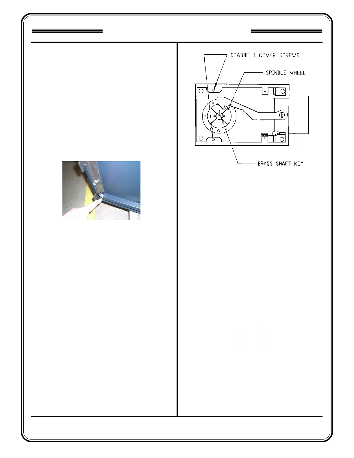
Figure 2 Mechanical combination lock (cover
removed).
Figure 1. Latch catch closed, holding
lock bar in raised (unlocked) position.
Allow the lock bar to stay in this position. You will be
directed to manually release the latch catch to test
the operation of the electronic lock in a later step.
2. Remove the two screws that attach the deadbolt
cover to the deadbolt and remove the cover.
3. Remove the brass shaft key located in the center of
the spindle by pulling directly out on it with a pair of
pliers (see Figure 1). Unscrew the outer combination
dial from the black spindle wheel and remove both
the dial and the wheel from the lock assembly.
4. Remove the four screws that attach the deadbolt
assembly to the inside of the door and remove the
deadbolt assembly.
5. Remove the two screws that attach the dial plate to
the cabinet door and remove the dial plate.
TRITON SYSTEMS
2
Page 3
ELECTRONIC LOCK INSTALLATION
MODEL 9100 CASH DISPENSER
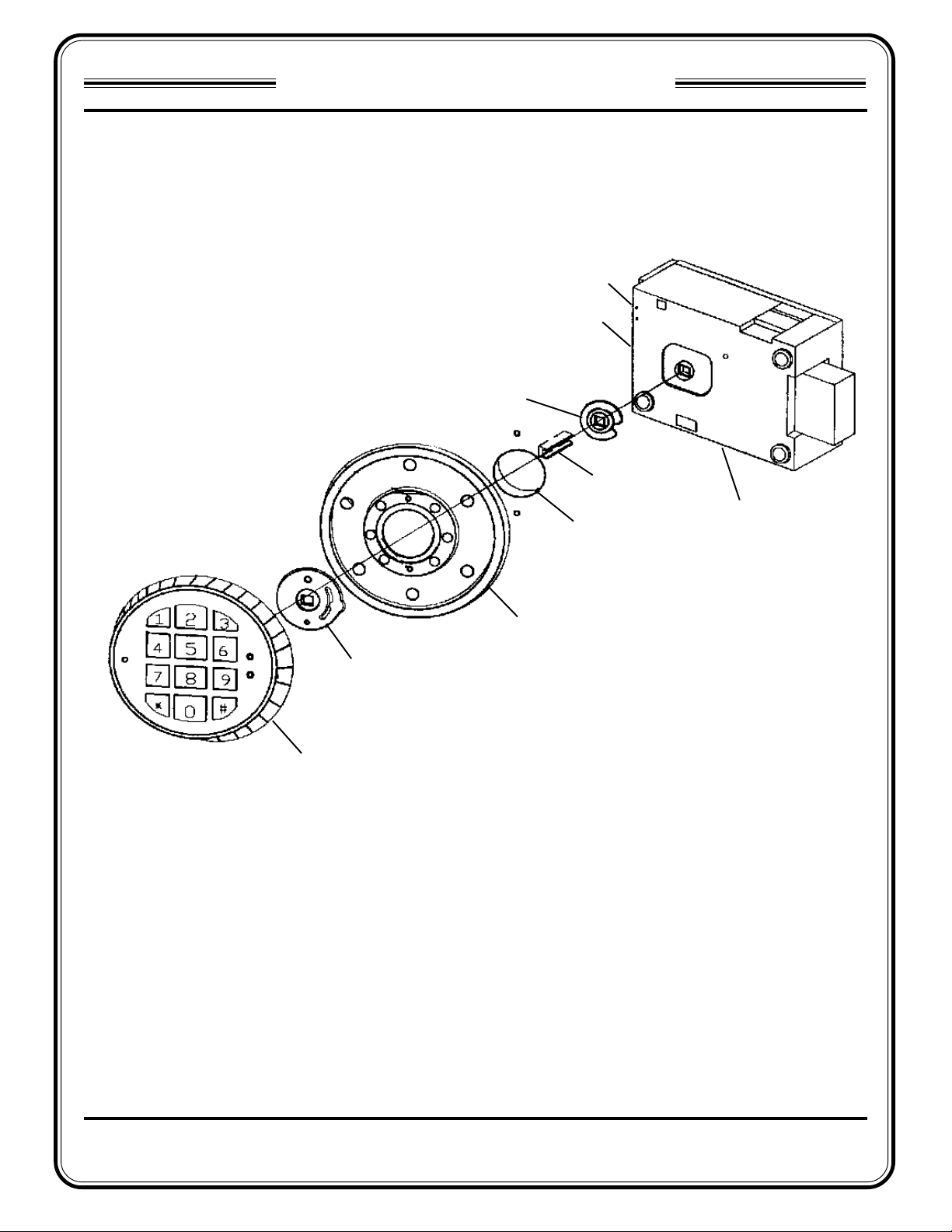
Electronic Lock Assembly Diagram
“ENT” Connector
“BAT” Connector
Deadbolt Bushing
Brass Spindle
Hole in Cabinet Door.
Deadbolt Assembly
Keypad Bushing
Electronic Lock Keypad
Figure 3. Electronic lock components.
Keypad Mounting Plate
TRITON SYSTEMS
3
Page 4

ELECTRONIC LOCK INSTALLATION
MODEL 9100 CASH DISPENSER
Electronic Lock Installation Procedure
After removing the mechanical lock, follow these steps
to install the electronic combination lock:
1. Apply a small amount of Locktite to the threads of
the included #8-32 shoulder screws. Attach the
keypad mounting plate to the cabinet door using
the two shoulder screws.
#8-32 Shoulder Screws
Mounting Plate
Figure 1. Attach Electronic Lock
Mounting Plate.
2. Place the 1-inch long brass spindle into the back
of the Electronic Lock Keypad as shown below.
Make sure the cable is positioned in the channel
on the brass spindle. Slide the keypad bushing
over the cable and the spindle so that it fits flat on
the back of the keypad.
3. Insert the end of the keypad cable through the hole
in the mounting plate and align the shoulder screws
with the mounting slots in the back of the keypad.
Figure 3. Insert keypad cable through
hole in mounting plate. Align large holes
in keypad mounting slots with shoulder
screws on mounting plate.
4. Align the large holes in the keypad mounting slots
with the heads of the shoulder screws. Place the
keypad on the shoulder screws and turn it about 10
degrees clockwise to lock it onto the mounting
plate. The keypad should turn freely.
IMPORT ANT : If the keypad DOES NOT turn freeIy ,
remove the keypad, back the shoulder screws
out 1/4-turn, replace the keypad and check the
fit again. Continue this process until the keypad
turns freely.
Keypad Bushing
Figure 2. Insert Brass Spindle. Slide
Keypad Bushing over spindle and cable.
The keypad mounting slots are used to
attach keypad to mounting plate.
TRITON SYSTEMS
Brass Spindle
Cable
Mounting Slots
Figure 4. Turn 10 degrees clockwise to
lock to mounting plate.
4
Page 5

ELECTRONIC LOCK INSTALLATION
MODEL 9100 CASH DISPENSER
5. Next, slide the deadbolt bushing over the end of
the keypad cable so that it rests over the brass
spindle, flush with the inside of the door.
Deadbolt Bushing
Figure 5. Slide deadbolt bushing over
brass spindle.
Figure 7. Cable curves over top of
bushing and exits to the right, as shown.
7. To install the lock (deadbolt assembly), insert the
deadbolt though the cutout in the sliding locker bar.
Next, align the brass spindle so that it falls into the
square cutout located on the back of the lock.
6. IT IS VERY IMPORTANT THAT THE KEYPAD
CABLE BE ROUTED EXACTLY AS SHOWN!
Failure to do so may result in the lock
malfunctioning and thereby locking the cabinet.
The keypad cable must exit through the cutout in
the deadbolt bushing, curve over the top of the
bushing, and exit on the right, as shown in the figures
below.
Brass Spindle
Cable
Deadbolt Bushing
Figure 6. Route cable through cutout in
deadbolt bushing.
Once aligned, the lock should sit flush with the
mounting plate. Install the three mounting screws
to hold the lock in place. Plug the keypad cable into
the top connector labeled “ENT” located on the lock.
ENT Connector
Figure 8. Install Lock. Plug Cable into
ENT connector on lock.
8. Peel off the adhesive backing on the battery box
and attach it to the inside of the door. NOTE: For
better adhesion, clean the area of the door with
alcohol prior to attaching the battery box.
Battery Box
TRITON SYSTEMS
Figure 9. Attach battery box to inside of
door.
5
Page 6

ELECTRONIC LOCK INSTALLATION
MODEL 9100 CASH DISPENSER
9. Plug the end of the battery cable lead into the lower
receptacle on the lock marked BAT.
BAT Connector
Figure 10. Plug Battery cable into BAT
connector on lock.
10. Attach two tye wrap clips on to the rear of the door
as shown. Loop up the excess cables and attach
them in place to the clips using two tye wraps.
Cable Clips
Figure 11. Loop excess lengths of
cables and secure in place using tye
wrap clips and tye wraps.
11. Place the lock bracket back onto the back of the
lock and attach using the 1/4-inch bolt. If there is
a label on the back of the lock bracket warning the
user about proper combination settings, remove the
label. The label only applies to mechanical locks.
12. TEST THE LOCK THOROUGHLY BEFORE
CLOSING THE DOOR! To do this, lift up on the
door handle (to releave pressure on the latch
mechanism), then push down on the latch lever to
disengage the catch that holds the lock bar in the
raised position. Use the door handle to carefully
lower the lock bar to its rest (locked) position.
Latch Lever
Figure 13. Push down on latch lever to
open catch and allow lock bar to lower
into locked position.
Next, turn the lock keypad counterclockwise to the
locked position. Try to lif t the door handle; the handle
should not move. Enter 1-2-3-4-5-6 into the keypad
and then turn the lock keypad clockwise to unlock
the lock. Lift up on the door handle to raise the lock
bar. The latch catch should snap into position
underneath the lock bar to hold it in the raised
(unlocked) position. Release the door handle.
13. It is recommended that you repeat the previous step
three times to verify the lock is operating properly.
IMPORTANT!!
BEFORE CLOSING THE CABINET DOOR,
LIFT UP ON THE DOOR HANDLE TO ALLOW
THE LOCK BAR LATCH TO ENGAGE.
Figure 12. Attach lock bracket using 1/
4-inch bolt.
TRITON SYSTEMS
Lock bracket back
14. See the next section for details on entering and
changing the combination and replacing a dead/bad
battery.
6
Page 7

ELECTRONIC LOCK INSTALLATION
MODEL 9100 CASH DISPENSER
Operating the Electronic Lock
Entering the Combination
The electronic lock combination consists of six digits.
Upon arrival, the combination of the lock should already
be preset to 1-2-3-4-5-6.
Follow these steps to enter the combination and
open the lock:
1. Enter the preset combination and check for proper
operation. After each keypress, the lock will beep.
After the final digit has been entered, the lock will
beep twice, and the open period will begin.
2. When a valid combination has been entered, the
operator will have approximately 3 seconds to open
the lock.
3. To open the lock, turn the keypad clockwise.
4. After the lock is opened, the handle may be lifted up
and the cabinet door opened.
Changing the Combination
WARNING!!
WARNING! NEVER LEAVE THE FACTORY
DEFAULT COMBINATION IN THE LOCK!
CHANGE THE COMBINATION AS SOON AS
POSSIBLE TO HELP PROTECT THE SECURITY OF THE VAULT.
Follow these steps to change the combination:
1. Unlock and open the security cabinet.
2. Repeat the previous step three times to verify the
lock is operating properly.
3. Enter six zeros.
4. Enter the current combination. (Initially set at 1-2-34-5-6)
Lockout Feature
The lock includes a WRONG TRY PENALTY lockout feature that prevents entry from unauthorized personnel.
This feature performs as follows:
• Entry of four consecutive invalid combinations will
disable the lock for 5 minutes.
• During this lockout period, the panel LED will flash
every 10 seconds. During this time no other combination entries will be allowed.
• At the end of the lockout period, if two more consecutive invalid combinations are entered, the 5minute lockout period will restart.
5. Enter the new combination twice.
6. The combination is now changed.
7. TEST THE NEW COMBINATION THOROUGHLY
BEFORE CLOSING THE DOOR! Refer to Step 12
of the procedure on Page 6 for instructions on testing the lock. When directed to enter the combination, use the new combinatio!
8. Repeat the previous step three times to verify the
lock is operating properly.
IMPORTANT!!
BEFORE CLOSING THE CABINET DOOR,
LIFT UP ON THE DOOR HANDLE TO ALLOW
THE LOCK BAR LATCH TO ENGAGE.
9. Close and lock the security cabinet.
TRITON SYSTEMS
7
Page 8

ELECTRONIC LOCK INSTALLATION
MODEL 9100 CASH DISPENSER
Bad Battery/Battery Replacement
If the lock beeps repeatedly while open, or beeps twice
and refuses to open, the 9-volt battery, located in the
battery box on the inside of the door, is weak or dead
and needs to be replaced.
IMPORTANT
If the lock will not operate (i.e. no signal from
the panel when a button is pressed) while the
door is closed and locked, the battery is dead
and the lock must be energized from the two
external terminals on the front, right side of the
push-button panel.
To energize the lock, connect a 9-volt battery
across the external terminals with the negative
terminal of the battery facing up. Continue to
hold the battery against the terminals as you
enter the combination and open the lock.
Follow these steps to replace a battery:
1. Unlock and open the ATM vault door.
2. Pull gently on the front cover of the battery box and
slide the cover off.
3. Remove the old battery. Install a new battery and
replace the front cover.
4. TEST THE OPERATION OF THE LOCK BEFORE
CLOSING THE DOOR! Refer to Step 12 of the procedure on Page 6 for instructions on testing the lock.
When directed to enter the combination, use the
current combinatio!
IMPORTANT!!
BEFORE CLOSING THE CABINET DOOR,
LIFT UP ON THE DOOR HANDLE TO ALLOW
THE LOCK BAR LATCH TO ENGAGE.
5. Close and lock the ATM vault door.
TRITON SYSTEMS
8
 Loading...