

Page 1

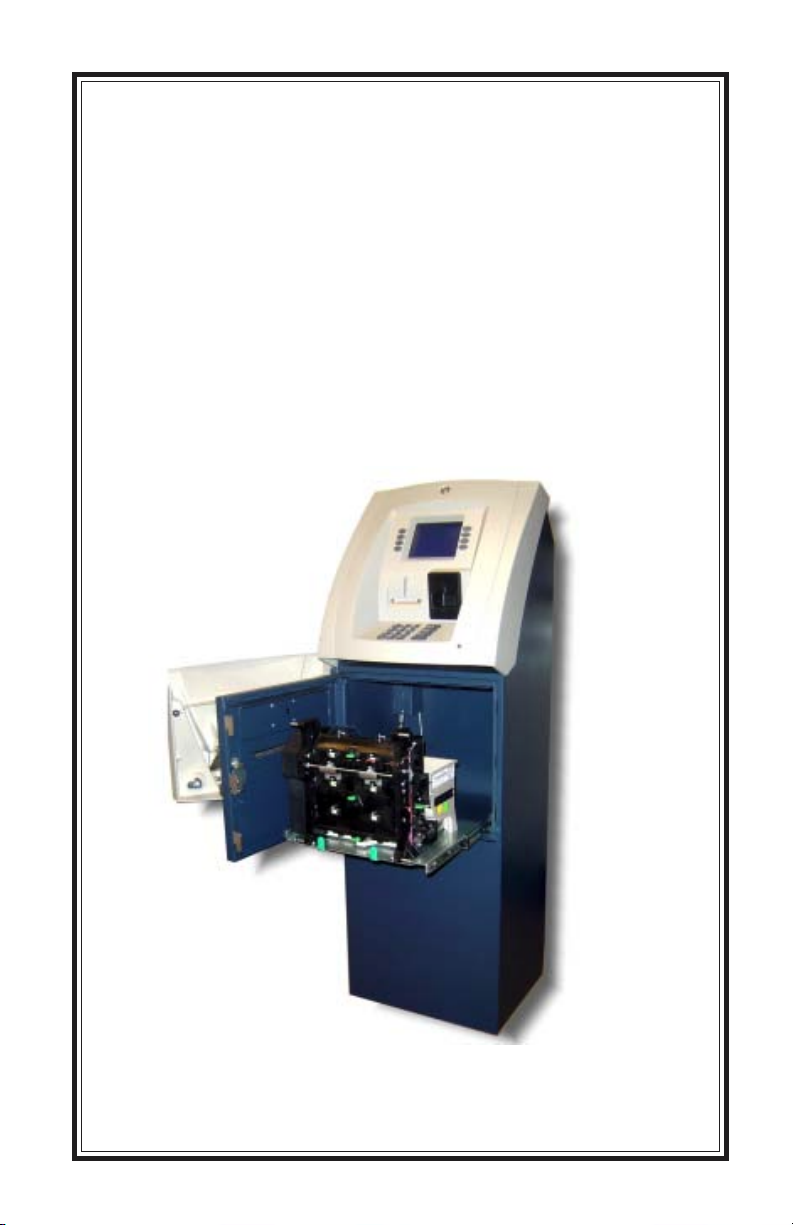
MODEL 8100
AUTOMATED TELLER MACHINE
USER / INSTALLATION MANUAL
VERSION 1.0
TDN 07100-00055 12/2005
CORPORATE HEADQUARTERS: RMA (RETURN MATERIAL AUTHORIZATION)
RETURN ADDRESS:
522 E. Railroad Street 21405 Avenue “B”
Long Beach, MS 39560 Long Beach, MS 39560
Phone: (228) 868-1317
Fax: (228) 868-0437
COPYRIGHT NOTICE
© 2005 Delaware Capital Formation, Inc. All Rights Reserved. TRITON, TRITON
WHERE MONEY COMES FROM, TRITON WAVES, DOVER and DOVER logo are
registered trademarks of Delaware Capital Formation, Inc., a wholly-owned subsidiary of
Dover Corporation.
Page 2

MODEL 8100 USER / INSTALLATION MANUAL
DISCLAIMER
The manufacturer of the Automated Teller Machine (ATM) product(s) described
herein makes no representations or warranties, either expressed or implied, by or
with respect to anything in this manual, and shall not be liable for any implied
warranties of fitness for a particular purpose or for any indirect, special, or
consequential damages. Information in this document is subject to change
without notice and does not represent a commitment on the part of the
manufacturer.
** CAUTION **
Changes or modifications not expressly approved by Triton
Systems could void the regulatory compliance approval
and the warranty. Use of this product in a manner other
than those described in this manual may result in personal
injury!
FCC COMPLIANCE
Statement of Compliance: This equipment complies with Part 68 of the FCC
rules. Located in the control area of the ATM is the product label. This label
lists the FCC registration number and ringer equivalence number of the unit. If
requested, this information must be provided to the telephone company. USOC/
FIC Codes: When ordering service from the telephone company for the Model
8100 ATM, the following information should be supplied:
Universal Service Order Code (USOC): RJ-11C
The Facility Interface Code (FIC): 02LS2
Plug and Jack: The plug and jack used to connect this equipment to premise
wiring and telephone network must comply with the applicable FCC Part 68 rules
and requirements adopted by ACTA. A compliant telephone cord and modular
plug is provided with this product. The telephone cord is designed to be
connected to a compatible modular jack that is also compliant.
Ringer Equivalent Number (REN): The REN is used to determine the number of
the devices that may be connected to a telephone line. Excessive RENs on a
telephone line may result in the devices not ringing in response to an incoming
call. In most but not all areas, the sum of the RENs should not exceed five (5). To
be certain of the number devices that may be connected to a line, as determined
by the local RENs, contact the local telephone company.
ii
Page 3

MODEL 8100 USER / INSTALLATION MANUAL
Harm to the Network: If the Model 8100 ATM causes harm to the telephone
network, the telephone company will notify the customer that a temporary
discontinuous of service may be required. If advanced notice is not possible,
the telephone company will notify the customer as soon as possible. You will be
advised of your right to file a complaint with the FCC if you believe it’s necessary.
Notification of Changes in Telephone Company Equipment: The telephone
company may make changes in its facilities, equipment, operations, or procedures
that could affect the operation of the equipment. If this happens, the telephone
company will provide advanced notice in order for you to make necessary
modifications to maintain uninterrupted service.
Repairs and Returns: If telecom compatibility trouble is experienced with the
Model 8100 ATM, you may contact for repairs and warranty information: Triton
at 1-228-868-1317
Triton Systems of Delaware, Inc.
522 East Railroad Street
Long Beach, MS 39560
If the equipment is causing harm to the network, the telephone company may
request that you disconnect the equipment until the problem is resolved. Repairs
should be made only by qualified factory representatives.
Party Lines: The Model 8100 ATM must not be used on party lines.
Alarm Equipment: The Model 8100 ATM should have its own dedicated phone
line. Do not install the 8100 on the same line as alarm equipment.
Electrical Safety Advisory: Telephone companies report that electrical surges,
typically lightening transients, are very destructive to customer equipment
connected to AC power sources. This has been identified as a major nationwide
problem. A commercially available, power surge suppressor, is recommended
for use with the Model 8100 to minimize damage in the event of an electrical
surge.
CANADIAN IC COMPLIANCE
NOTICE:
The Industry Canada label identifies certified equipment. This certification
means that the equipment meets telecommunications network protective, operational, and safety requirements as prescribed in the appropriate Terminal Equipment Technical Requirements document(s). The department does not guarantee the equipment will operate to the user’s satisfaction.
iii
Page 4

MODEL 8100 USER / INSTALLATION MANUAL
Before installing this equipment, users should ensure that it is permissible to be
connected to the facilities of the local telecommunications company. The equipment must also be installed using an acceptable method of connection. The
customer should be aware that compliance with the above conditions may not
prevent degradation of service in some situations.
Repairs to certified equipment should be coordinated by a representative designated by the supplier. Any repairs or alterations made by the user to this
equipment or equipment malfunctions may give the telecommunications company cause to request the user to disconnect the equipment.
Users should ensure for their own protection that the electrical ground connections of the power utility, telephone lines and internal metallic water pipe system, if present, are connected together. This precaution may be particularly
important in rural areas. Caution: Users should not attempt to make such connections themselves, but should contact the appropriate electric inspection
authority or electrician, as appropriate.
NOTICE:
The Ringer Equivalence Number (REN) assigned to each terminal device provides an indication of the maximum number of terminals allowed to be connected
to a telephone interface. The termination on an interface may consist of any
combination of devices subject only to the requirement that the sum of the
Ringer Equivalence Numbers of all the devices does not exceed 5.
AVIS:
L’étiquette d’Industrie Canada identific le matériel homologué. Cette étiquette
certifie que le matériel est conforme aux normes de protection, d’exploitation et
de sécurité des réseaux de télécommunications, comme le prescrivent les documents concernant les exigences techniques relatives au matériel terminal. Le
Ministère n’assure toutefois pas que le matériel fonctionnera à la satisfaction de
l’utilisateur.
Avant d’installer ce matériel, l’utilisateur doit s’assurer qu’il est permis de le
raccorder aux installations de 1’entreprise locale de télécommunication. Le
matériel doit également être installé en suivant une méthode acceptée de
raccordement. L’abonné ne doit pas oublier qu’il est possible que la comformité
aux conditions énoncées cidessus n’empêche pas la dégradation du service
dans certaines situations.
iv
Page 5

MODEL 8100 USER / INSTALLATION MANUAL
Les réparations de matériel homologué doivent être coordonnées par un
représentant désigné par le fournisseur. L’entreprise de télécommunications
peut demander à I’utilisateur de débrancher un appareil à la suite de réparations
ou de modifications effectuées par l’utilisateur ou à cause de mauvais
fonctionnement.
Pour sa propre protection, l’utilisateur doit s’assurer que tous les fils de mise à
la terre de la source d’énergie électrique, des lignes téléphoniques et des
canalisations d’eau métalliques, s’fl y en a, sont raccordés ensemble. Cette
précaution est particulièrement importante dans les régions rurales.
Avertissement: L’utilisateur ne doit pas tenter de faire ces raccordements luimême; il doit avoir recours à an service d’inspection des installations électriques,
ou à un électricien, selon le cas.
AVIS:
L’indice d’équivalence de la sonnerie (IES) assigné à chaque dispositif terminal
indique le nombre maximal de terminaux qui peuvent étre raccordés à une interface. La terminaison d’une interface téléphonique peut consister en une
combinaison de quelques dispositifs, à la seule condition que la somme d’indices
d’équivalence de la sonnerie de tous les dispositifs n’exède pas 5.
UNITED KINGDOM
This equipment has been approved in accordance with Council Decision 98/
482/EC for pan-European single terminal connection to the Public Switched
Telephone Network (PSTN). However, due to differences between the individual PSTNs provided in the different countries, the approval does not, of
itself, give unconditional assurance of successful operation on every PSTN
network termination point. In the event of problems, contact your equipment
supplier in the first instance. This unit uses only Dual-Tone Multi-Frequency
(DTMF) address signaling.
EMISSIONS (EMI)
This device complies with Part 15 of the FCC rules. Operation is subject to the
following two (2) conditions:
1. This device may not cause harmful interference.
2. This device must accept any interference received, including interference
that may cause undesired operation.
v
Page 6

MODEL 8100 USER / INSTALLATION MANUAL
NOTE:
This equipment has been tested and found to comply with the limits for a Class
A digital device, pursuant to Part 15 of FCC rules. These limits are designed to
provide reasonable protection against harmful interference when the equipment
is operated in a commercial environment. This equipment generates, uses, and
can radiate radio frequency energy and, if not installed and used in accordance
with the instruction manual, may cause harmful interference to radio
communications. Operation of this equipment in a residential area is likely to
cause harmful interference in which case the user will be required to correct the
interference at his own expense. Changes or modifications to this unit not
expressly approved by the party responsible for compliance could void the
user’s authority to operate the equipment.
CANADIAN EMISSION R EQUIREMENTS
This digital apparatus does not exceed the Class A limits for radio noise emissions
from digital apparatus set in the Radio Interference Regulations of the Canadian
Department of Communications. This Class A digital apparatus complies with
Canadian ICES-003.
Le present appareil numerique n’emet pas de bruits radioelectriques depassant
les limites applicables aux appareils numeriques de la Class A prescrites dans le
Reglement sur le brouillage radioelectrique edicte par le ministere des
Communications du Canada. Cet appareil numerique de la classe A est conforme
a la norme NMB-003 Canada.
UK / AUSTRALIAN EMISSION REQUIREMENTS
WARNING:
This is a Class A product. In a domestic environment, this product may cause
radio interference in which case the user may be required to take adequate
measures.
vi
Page 7

MODEL 8100 USER / INSTALLATION MANUAL
NOTICES
Copyright © Delaware Capital Formation, Inc., 2005.
ALL RIGHTS R ESERVED
This publication is protected by copyright and all rights are reserved. No part of
it may be reproduced or transmitted by any means or in any form, without prior
consent in writing from Triton Systems of Delaware, Inc.
The information in this publication has been carefully checked and is believed
to be accurate. However, Triton Systems of Delaware, Inc. assumes no responsibility for any inaccuracies, errors, or omissions that may be contained in this
document. In no event will Triton Systems of Delaware, Inc. be liable for direct,
indirect, special, incidental, or consequential damages resulting from any defect
or omission in this manual, even if advised of the possibility of such damages.
In the interest of continued product development, Triton Systems of Delaware,
Inc. reserves the right to make improvements in its documentation and the
products it describes at any time, without notice or obligation.
TRADEMARK A CKNOWLEDGEMENTS
Microsoft Windows is a registered trademark of Microsoft Corporation in the
United States and/or other countries. Triton Connect is a trademark of Triton
Systems of Delaware, Inc. CashWorks is a trademark of CashWorks,Inc. PaySpot
is a trademark of Euronet Worldwide. Western Union is a registered trademark
of Western Union Holdings, Inc. MultiModem is a trademark of Multi-Tech
Systems, Inc. Verizon Wireless is a trademark of Verizon Trademark Services,
LLC. VISA® is a registered trademark of VISA of the United States and other
countries.
vii
Page 8

MODEL 8100 USER / INSTALLATION MANUAL
WARRANTY STATEMENT
Manufacturer warrants that the products delivered to a distributor will perform
in accordance with the Manufacturer’s published specifications for thirteen
months from date of shipment in Long Beach, MS.
Manufacturer’s warranty shall not apply to any damage resulting from abuse,
negligence, accident, or to any loss or damage to the products while in transit.
Written notice and explanation of circumstances surrounding any claims that
the goods have proved defective in material or workmanship shall be given
promptly from the distributor to the manufacturer. No claim may be made, or
action brought, by or through a distributor after the expiration of 14 months
following any alleged breach of warranty.
Distributor’s sole and exclusive remedy in the event of defect is expressly
limited to the replacement or correction of such defective parts by manufacturer at its election and sole expense, except there shall be no obligation to
replace or repair items which, by their nature, are expendable. If Manufacturer
is unable to replace or repair the defective parts, Manufacturer shall refund to
Distributor that portion of the purchase price allocable pays to such goods.
No representation or other affirmation of fact not set forth herein, including but
not limited to statements regarding capacity, suitability for use, or performance
of the goods, shall be or be deemed to be a warranty or representation by
Manufacturer for any purpose, nor give rise to any liability or obligation of
Manufacturer whatever.
Except as specifically provided in this document, there are no other warranties
expressed or implied including, but not limited to, any implied warranties or
merchantability or fitness for a particular purchase.
L
IMITATION OF LIABILITY
In no event shall manufacturer be liable for loss of profits or incidental, indirect, special, consequential or other similar damages arising out of any breach
of this contract or obligations under this contract.
DEFENSE OF INFRINGEMENT CLAIMS
If notified promptly in writing of any action (and all prior claims relating to such
action) brought against the Distributor based on a claim that Distributor’s use of
the goods infringes a patent or other intellectual property right, and if given
access by Distributor to any information distributor has regarding such alleged
infringement, Manufacturer agrees to defend Distributor in such action at its
expense and will pay any costs or damages finally awarded against Distributor
in any such action, provided the Manufacturer shall have had sole control of
viii
Page 9

MODEL 8100 USER / INSTALLATION MANUAL
the defense of any such action and all negotiations for its settlement or compromise.
In the event that a final injunction shall be obtained against the Distributor’s use
of the goods or any of their parts by reason of infringement of a patent or other
intellectual property right or if in Manufacturer’s opinion the goods are likely to
become the subject of a claim of infringement of a patent or other intellectual
property right, Manufacturer will, at its option and at its expense, either procure
for the Distributor the right to continue using the goods, replace or modify the
same so they become non-infringing or grant the Distributor a credit for such
goods as depreciated and accept their return. The depreciation shall be an equal
amount per year over the lifetime of the goods as established by Manufacturer.
Manufacturer shall not have any liability to the Distributor under any provision
of this clause if any infringement, or claim thereof, is based upon: (i) the use of
the goods in combination with other goods or devices which are not made by
Manufacturer; (ii) the use of the goods in practicing any process; (iii) the furnishing to the Distributor of any information, date, service, or applications assistance; or (iv) the use of the goods with modifications made by the Distributor.
The Distributor shall hold Manufacturer harmless against any expense, judgment or loss for infringement of any patent or other intellectual property right
which results from Manufacturer’s compliance with the Distributor’s designs,
specifications or instructions. No costs or expenses shall be incurred for the
account of Manufacturer without the written consent of Manufacturer. The
foregoing states the entire liability of manufacturer with respect to infringement of patents or other intellectual property right by the goods or any part
thereof, or by their operation.
INTERPRETATION AND OTHER P AROLE EVIDENCE
This writing is intended by the parties as final expression of their agreement and
is intended also as a complete and exclusive statement of the terms of their
agreement. No course of prior dealing between the parties and no usage of the
trade shall be relevant to supplement or explain any term used in these terms and
conditions. Acceptance or acquiescence in a course of performance rendered
under these terms and conditions shall not be relevant to determine the meaning
of these terms and conditions even though the accepting or acquiescing party
has knowledge of the performance and opportunity for objection. Whenever a
term defined by the Uniform Commercial Code, as adopted in Mississippi, is
used in these terms and conditions, the definition contained in the code is to
control.
MODIFICATIONS
These terms and conditions can be modified or rescinded only by writing signed
by both the parties or their duly authorized agents.
ix
Page 10

MODEL 8100 USER / INSTALLATION MANUAL
WAIVER INEFFECTIVE
No claim or right arising out of or relating to a breach of these terms and conditions can be discharged in whole or in part by a waiver or renunciation of the
claim or right unless the waiver or renunciation is supported by consideration
and is in writing signed by the aggrieved party. Waiver by either Manufacturer
or Distributor of a breach by the other of any provision of these terms and
conditions shall not be deemed a waiver of future compliance therewith, and
such provisions shall remain in full force and effect.
STATUTE OF LIMITATIONS
Any action by the Distributor or Manufacturer for breach of these terms and
conditions must be commenced within one (1) year after the cause of action has
accrued.
APPLICABLE LAW
These terms and conditions shall be governed by and construed in accordance
with the provisions of the Uniform Commercial Code as adopted by the State of
Mississippi.
BANKRUPTCY
In the event of any proceedings, voluntary or involuntary, in bankruptcy or
insolvency by or against Distributor, or in the event of the appointment, with or
without the Distributor’s consent, of an assignee for the benefit of creditors or
of a receiver or of a liquidator, then Manufacturer shall be entitled to cancel any
unfilled part of these terms and conditions without any liability whatsoever.
PARTS ONLY LIMITED MANUFACTURER’S W ARRANTY
Triton Systems of Delaware, Inc. warrants the components of each Model 9100
series ATM, excluding software and related documentation, against any defect
in materials and/or workmanship for a period of 13 months from the shipping
date. If a component fails due to defects in materials and/or workmanship within
the warranty period, Triton will furnish a new or refurbished component, at its
discretion. Triton shall not be responsible for labor or other costs associated
with installing the components and the failed component shall be returned to
Triton at the purchaser’s expense. Triton shall not be responsible for misuse or
abuse of a unit and any attempts to remove or deface the serial number or date
code on a unit or any component thereof, or any attempt to repair a unit or to
repair or replace any component by anyone other than a service technician
authorized by Triton shall void this warranty.
x
Page 11

MODEL 8100 USER / INSTALLATION MANUAL
LIMITED WARRANTY COVERS NORMAL USE. TRITON DOES NOT WARRANT OR COVER
DAMAGE
• occurring during shipment of the equipment or components from or to
• caused by accident, impact with other objects, dropping, falls, spilled liq-
• caused by a disaster such as fire, flood, wind, earthquake, lightning, or
• caused by failure to provide a suitable installation environment for the
• caused by the use of the equipment for purposes other than those for
• resulting from improper maintenance;
• caused by any other abuse, misuse, mishandling, or misapplication.
Under no circumstances shall Triton or its suppliers be liable for any special,
incidental, or consequential damages based upon breach of warranty, breach of
contract, negligence, strict liability, or any other legal theory. Such damages
include, but are not limited to, loss of profits, loss of revenue, loss of data, loss
of use of the equipment or any associated equipment, cost of capital, cost of
substitute or replacement equipment, facilities or services, down time, purchaser’s
time, the claims of third parties, including customers, and injury to property.
:
Triton’s facilities;
uids, or immersion in liquids;
other acts of God;
equipment, including but not limited to, faulty wiring in the building in
which the equipment is installed, installation in a facility with uncontrolled
environmental conditions, failure to provide a dedicated electrical circuit on
which the equipment operates, and/or lack of proper earth grounding for
the equipment;
which it was designed;
DISCLAIMER OF WARRANTIES
The warranty stated above is the only warranty applicable to this product. All
other warranties, expressed or implied (including all implied warranties of merchantability or fitness for a particular purpose or quality of service), are hereby
disclaimed. No oral or written information, or advice given by Triton, its agents
or employees shall create a warranty or in any way increase the scope of this
warranty.
SHIPPING DAMAGE
All equipment is shipped Free On Board (FOB), Triton’s facilities. The organization or individual who has purchased the equipment assumes responsibility for
the equipment once it leaves Triton’s facilities.
Should your equipment be damaged in the process of shipment or delivery to
your place of destination, we recommend the following course of action:
xi
Page 12

MODEL 8100 USER / INSTALLATION MANUAL
• If possible, call the shipping company before the driver leaves your deliv-
ery site. Make note of the damage on the “receipt of delivery’ paperwork. If
this is not possible, call them as soon as possible to report the damage.
• Take photographs of the damaged packaging prior to opening the boxes. If
this is not possible, make note of key points, such as whether the equipment is on a pallet, if the banding is intact, how the boxes are damaged, etc.
Keep all of the packaging for inspection by the shipping company.
• If you unpack the equipment, take photographs of the damaged equipment.
If this is not possible, make note of the damages.
• You must file a claim with the shipper for shipping damages immediately
after reporting the damages.
Should you specify the carrier, we recommend that you explore with this chosen
carrier the policies and procedures regarding shipping damage claims prior to
selecting them as your preferred carrier.
If the equipment receives structural damage and is in an un-installable condition, Triton will work with you to arrange for a replacement unit to be shipped as
soon as possible. The purchaser will be billed for the replacement unit. Triton’s
repair technicians will repair the damaged unit after it is returned to our facilities.
We will credit the purchaser’s account for the full purchase price of the damaged
unit, minus the cost of returning the unit to ‘like new” condition. Under no
circumstances does Triton authorize anyone to complete structural damage
repairs in the field. Therefore, we will not ship primary structural parts, such as
a cabinet head or main cabinet body for repair in the field.
AUTHORIZED INSTALLATION AND SERVICE PROVIDERS
Triton utilizes several nationwide and regional authorized third party maintenance providers. All ATMs must be installed and serviced by service technicians certified by Triton. This includes authorized third party service technicians and technicians who have been factory trained by Triton to service ATM
equipment. Installation or repairs attempted by unauthorized service technicians automatically voids the warranty on the product.
Please contact Triton’s Technical Services department at (800) 259-6672 for a list
of our third party service providers and/or to obtain information on the requirements and procedures for becoming a certified Triton service technician.
xii
Page 13

MODEL 8100 USER / INSTALLATION MANUAL
TRITON’S TECHNICAL SERVICES DEPARTMENT
The primary purpose of the Technical Services Department is to provide assistance to customers in the operation, trouble shooting, and repair of equipment
manufactured by Triton. A toll-free phone number (1-800-259-6672) is provided
for convenience. The Technical Services department operates to serve our
customers. The staff is trained to follow our policies and procedures to ensure
fair and uniform treatment of all our customers.
AUTOMATED VOICE MAIL SYSTEM
Our goal is to have a ‘live’ person answer 100% of all incoming calls (during
regular support hours). On occasion, however, call loads may exceed the capacity of the staff. When this occurs, an automated voice mail system will answer
the call, indicate to the caller that all Technical Support specialists are busy
assisting others, and ask the caller to leave detailed information about the nature of the call.
Should it become necessary to leave a voice mail message, the caller should
state:
• their name,
• the organization for which they work,
• the serial number of the equipment they are calling about,
• detailed description of the problem that they are experiencing, and
• phone number where they can be reached, including area code.
As Technical Support specialists become available, they check for voice mail
messages and return calls in the order in which they were received. By providing the information requested in the voice mail, the technician can be prepared
when your call is returned. Triton asks you to be patient if you must leave voice
mail and assures you that your call is important to us and that we will respond
promptly.
CALLS FOR SERVICE OR R EPAIR
Calls for service or repair will be accepted from authorized service technicians
only. End users must contact either the sales organization that placed the
equipment or an authorized third party service organization to obtain service.
The sections that follow describe the policies and procedures that relate to the
repair and replacement of malfunctioning equipment.
xiii
Page 14

MODEL 8100 USER / INSTALLATION MANUAL
QUESTIONS ON OPERATION OF EQUIPMENT
Technical support is available to owners of Triton equipment and to qualified
service personnel. When calling for help with the configuration or operation of
a Triton product, the caller must provide either positive identification as a service technician or the serial number of a Triton terminal. Technical support is
provided during normal business hours for the life of the product.
When calling for help with an operational problem, please have available information pertaining to the nature of the trouble. This includes the type of equipment, examples of what is or is not happening, and the name of the processor
that supports your terminal.
All questions pertaining to the settlement of accounts, transaction inquiries,
and fund status must be directed to the processor. Triton does not have access
to the information needed to answer questions relating to specific transactions.
CONTACT I NFORMATION
Triton Systems of Delaware, Inc.
522 East Railroad Street
Long Beach, MS 39560
SALES:
1 (800) 367-7191
1 (228) 868-1317
1 (228) 868-0437 (fax)
SERVICE:
1 (800) 259-6672 (Technical Support)
1 (228) 575-3229 fax (Technical Support)
1 (228) 868-0859 fax (Parts)
xiv
Page 15

MODEL 8100 USER / INSTALLATION MANUAL
Contents
SECTION 1 - INTRODUCTION ........................................................ 1
WHAT’S IN THIS MANUAL ................................................................................ 2
FEATURE HIGHLIGHTS ....................................................................................... 3
STANDARD FEATURES ....................................................................................... 4-5
SECTION 2 - BASIC OPERATION ................................................... 7
INTRODUCTION ................................................................................................. 8
CONTROL PANEL LAYOUT ................................................................................. 9
FUNCTION KEYPADS ......................................................................................... 10
MAIN KEYPAD ................................................................................................ 10
MENU-BASED OPERATION ................................................................................ 12
CUSTOMER TRANSACTIONS ................................................................................ 13
VOICE-ENABLED TRANSACTIONS ....................................................................... 15
SECTION 3 - MANAGEMENT FUNCTIONS ....................................... 17
INTRODUCTION ................................................................................................. 18
ACCESSING THE MANAGEMENT FUNCTIONS MENU ............................................. 18
NEW / MODIFIED MANAGEMENT FUNCTIONS ..................................................... 19
MAIN MENU ................................................................................................... 20
CONFIGURE TERMINAL ...................................................................................... 21-22
CASSETTE SETUP .......................................................................................... 23
CASSETTE PARAMETERS ................................................................................. 24
CONFIGURE PROCESSORS .................................................................................. 25-27
KEY MANAGEMENT ......................................................................................... 28-30
CONFIGURE SERVICES .................................................................................... 31
STD ATM CONFIGURATION ........................................................................... 32
PAY SPOT CONFIGURATION ............................................................................. 33
CASHWORKS CONFIGURATION ....................................................................... 34
W ESTERN UNION CONFIGURATION ................................................................... 35-36
CASSETTE SERVICE ......................................................................................... 37
DIAGNOSTICS ........................................................................................................ 38-40
CLOSE ............................................................................................................ 41
CASSETTE CLOSE .......................................................................................... 42
JOURNAL ........................................................................................................ 43
TCP/IP (ETHERNET) CONFIGURATION .......................................... 45
INTRODUCTION ................................................................................................. 46
TCP/IP ADDRESSES ......................................................................................... 46
CONFIGURE PROCESSOR ................................................................................. 47
COMMUNICATION TYPE ................................................................................. 47
COMMUNICATION N UMBERS ........................................................................... 48
xv
Page 16

MODEL 8100 USER / INSTALLATION MANUAL
Contents
CONFIGURE TERMINAL ................................................................................... 49
TCP/IP CONFIGURATION ............................................................................... 49
NETWORK SETTINGS ......................................................................................... 50-51
TEST TCP/IP ................................................................................................... 52
TRITON CONNECT TCP/IP CONFIGURATION .................................................... 53
HOST NUMBERS ............................................................................................ 54
ALARM NUMBERS ......................................................................................... 55
TERMINAL IP ADDRESS / LISTENING P ORT ...................................................... 56
CDMA (WIRELESS) CONFIGURATION .......................................... 57
INTRODUCTION ................................................................................................. 58
TCP/IP ADDRESSES ......................................................................................... 58
CONFIGURE PROCESSOR ................................................................................. 59
COMMUNICATION TYPE ................................................................................. 59
COMMUNICATION N UMBERS ........................................................................... 60
CONFIGURE TERMINAL ................................................................................... 61
NETWORK S ETTINGS ..................................................................................... 62
TRITON CONNECT WIRELESS CONFIGURATION ................................................ 63
HOST NUMBERS ............................................................................................ 64
ALARM NUMBERS ......................................................................................... 65
TERMINAL IP ADDRESS / LISTENING P ORT ...................................................... 66
WIRELESS DIAGNOSTICS ................................................................................. 67
MODEM STATUS ................................................................................................ 68-69
SIGNAL STRENGTH / REACTIVATE MODEM ...................................................... 70
SECTION 4 - CASSETTE CLOSE / CASH REPLENISHMENT ................. 71
INTRODUCTION ................................................................................................. 72
DISPENSING MECHANISM ................................................................................. 72
NOTE CONDITION ............................................................................................. 72
PREPARING NOTES ........................................................................................... 73
CASSETTE CLOSE ............................................................................................ 74
REPLENISHING CASSETTE (TDM-50) ............................................................... 75
SECTION 5 - GENERAL MAINTENANCE ........................................... 77
INTRODUCTION ................................................................................................. 78
REPLENISHING THE RECEIPT PAPER ..................................................................... 78-80
CLEANING THE ENCLOSURE .............................................................................. 81
CLEANING THE DISPLAY ................................................................................... 81
CARD READER CLEANING ................................................................................. 81
xvi
Page 17

MODEL 8100 USER / INSTALLATION MANUAL
Contents
SECTION 6 - TDM ERROR CODES / CLICK COUNTS .................... 83
TDM ERROR CODES ............................................................................................ 84-85
TDM HARDWARE STATUS CODES ...................................................................... 86
TDM CLICK COUNTERS ....................................................................................... 87-93
APPENDIX A - INSTALLATION PROCEDURES .................................... A-1
WHAT’S IN THIS APPENDIX ............................................................................... A-2
ATM INSTALLATION FOR ACCESSIBILITY .................................................... A-3 THRU A-9
ENVIRONMENTAL AND P OWER CHECKLIST .......................................................... A-10,11
CABINET (W/PLINTH) DIMENSIONS ........................................................ A-13 THRU A-16
PLINTH / CABINET / DISPENSER INSTALLATION ..................................... A-17 THRU A-29
POWER AND COMMUNICATION ............................................................................ A-31,32
APPENDIX B - COMBINATION LOCKS ........................................... B-1
INTRODUCTION ................................................................................................. B-2
OPERATING THE MECHANICAL LOCK ............................................................... B-2
CHANGING THE COMBINATION ....................................................................... B-3
OPERATING THE ELECTRONIC LOCK ................................................................ B-5
CHANGING THE COMBINATION ....................................................................... B-5
CHANGING THE BATTERY .............................................................................. B-6
xvii
Page 18

MODEL 9100 USER / INSTALLATION MANUAL
THIS PAGE INTENTIONALLY LEFT BLANK
xviii
Page 19
SECTION 1
INTRODUCTION
1
Page 20

MODEL 8100 USER / INSTALLATION MANUAL
WHAT’S IN THIS MANUAL
This User / Installation manual describes the operating features of the Model
8100 series ATM and shows how to perform the procedures that would typically be performed by the owner or operator personnel. It also includes installation procedures for the terminal.
The user manual is divided into the following sections:
Section 1, Introduction. Summarizes the basic features of the Model 8100 series
ATM.
Section 2, Basic Operation. Describes the ATMs user interface, explains how to
access Management Functions, and provides a basic description of operation
during typical customer transactions.
Section 3, Initial Setup. Lists the ATMs setup parameters and Management
Function flowchart.
Section 4, Currency Handling. Describes the standards for evaluating note
quality and describes how to replenish the cash in the note cassettes and how
to check for rejected notes.
Section 5, Management Functions. Describes the menu functions and available
options.
Section 6, Maintenance. Describes normal preventative and corrective maintenance procedures appropriate for user personnel.
Section 7, Error Recovery. Describes the ATM’s error reporting features and
error codes, gives a general error recovery procedure, and provides error recovery procedures to follow in case of specific error conditions.
Appendix A, Installation Procedures. Provides step-by-step procedures for
completing physical installation of the Model 8100 ATM.
Appendix B, Combination Locks. Covers how to change combinations for an
electronic lock. Also provides procedures for changing the battery in the electronic lock.
2
Page 21

INTRODUCTION
FEATURE HIGHLIGHTS
Important features of the 8100 series ATM are highlighted in the following list:
! Modular architecture eases troubleshooting and servicing.
! Supports dial-up, wireless, and Ethernet (TCP/IP) communications.
! Single cassette design using a TDM-50 (new) dispensing mechanism.
! 5.7" (145 mm) monochrome or color LCD display.
! 14.4 baud modem standard (33.6 baud optional).
! Satisfies Americans with Disabilities Act (ADA) specifications for height
and access. Audio compliant.
! VISA® Encrypting PIN Pad (VEPP) to comply with international encryption
standards and Triple DES compliant.
! Dip-style card reader (EMV optional).
! Non UL cabinet.
! 58 mm thermal printer designed for quiet operation. The 8100 terminal is
equipped with the APS CP MRS-250 printer. There is no graphics support
with the APS printer Receipt/coupon graphics cannot be printed to the
device.
! Key lock, mechanical, or electronic combination lock .
! Supports remote setup, configuration, and monitoring via Triton Connect™
ATM monitoring software.
! Dispenses U.S. and international currency types.
! High-capacity electronic journal stores transaction details for later printout
and analysis.
! Supports LED-backlit signage option (topper attachment).
! Small footprint design makes placement easier.
! Available in Bayou Bronze.
SNOISNEMID
htdiWhtpeD
)mm504("61)mm033("31)mm5421("2/194)mm4251("06
3
thgieH
)reppoto/w(
thgieH
)reppot/w(
Page 22

MODEL 8100 USER / INSTALLATION MANUAL
STANDARD FEATURES
! Management Functions. Enable extensive control and customization of the
ATM’s operating parameters.
! EPROM Functions. The EPROM function provides low-level diagnostic
and software update operations.
! Password Protection. Access to Management functions and EPROM areas
is protected with passwords.
! MAC Encryption Support. Message Authentication Code (MAC) data
encryption protocol. Provides increased protection for message traffic to
and from the ATM. Triple DES compliant.
! Encrypting PIN Pad (EPP) Entry Device Support. Secure EPP device
encrypts the customer PIN during a transaction. Triple DES compliant.
! Multi-Language Support. Enables the customer to select a preferred
language (such as French or Spanish) for customer screens and receipts.
! Transaction and Account Type Configuration. Enables selection of
transactions (transfers or balance inquiries) or accounts (savings or credit
card) that will be presented to the customer. Does not affect availability of
checking account withdrawal.
! Cassette and Day Close Reports. Provide summary information about the
number and type of transactions being performed by the ATM.
! Electronic Journal. Stores the details of each transaction in solid-state
memory. Journal data can be retrieved, printed out at the receipt printer, and
transferred to a remote Triton Connect computer.
! AD Screens. An Ad screen is a promotional or advertising graphic that is
displayed on the LCD screen during idle periods. Ad screens are
downloaded to the terminal by a remote Triton Connect™ computer. Textonly (non-graphic) Ad screens can also be displayed.
! Messages. Informational and promotional messages that are displayed to
the customer on-screen or printed on receipts.
4
Page 23

INTRODUCTION
! Coupons. Coupons are printed by the receipt printer and prizes awarded to
customers based on random and/or withdrawal amount-based transactions.
Coupon text can be entered locally or downloaded using Triton Connect
software.
! Status Monitoring. The ATM can periodically transfer status information
to the host processor. In addition, Triton Connect™ remote monitoring
software can be used to view the journal, monitor operation and alarm
conditions, update operating parameters, and reset the terminal.
! Front-access Cabinet. Allows access to the dispensing mechanism and
currency cassette from the control-panel side of the unit.
5
Page 24

MODEL 8100 USER / INSTALLATION MANUAL
THIS PAGE INTENTIONALLY LEFT BLANK
6
Page 25

SECTION 2
BASIC OPERATION
7
Page 26

MODEL 8100 USER / INSTALLATION MANUAL
INTRODUCTION
This section describes the basic operation of the terminal. The following topics
are covered:
1. CONTROL PANEL LAYOUT. Describes the layout of the terminal’s control panel.
2. KEYPAD OPERATION. Describes the use of the alphanumeric keypads.
3. MENU-BASED OPERATION. Gives a general overview of the terminal display
interface.
4. ACCESSING MANAGEMENT FUNCTIONS. Describes the password entry
procedure that must be followed in order to access the Management
Functions area.
5. CUSTOMER TRANSACTIONS. Summarizes the actions involved in typical
customer transactions. In addition, the voice-enabled transactions feature
is described.
8
Page 27
BASIC OPERATION
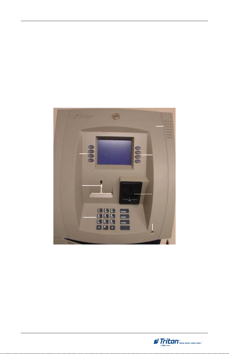
CONTROL PANEL LAYOUT
The user interface of the terminal consists of the LCD screen, receipt chute, card
reader, speaker, headphone jack (visually impaired), and 24 keys on three keypads. The Function keys are arranged in two four-key groups, one group on
either side of the LCD display. The main keypad consists of 10 alphanumeric
keys, two arrow keys and four large control keys, all located in a 16-key group
beneath the LCD screen.
The main keypad and control keys have an integral raised Braille symbol to
conform to the requirements of the Americans with Disabilities Act (Figure 2-1).
Speaker
Function
keys
Receipt
chute
Main
keypad
Figure 2-1. Control panel layout.
LCD screen
Function
keys
Card
reader
Headphone jack
9
Page 28

MODEL 8100 USER / INSTALLATION MANUAL
FUNCTION KEYPADS
The primary menu navigation keys, called Function keys, are arranged in two
four-key groups, one group on either side of the LCD screen. A Function key is
only active when a function or menu option name is displayed (if the display is
“grayed out”, that option is not available). The Function keys are designated F1
through F8, as shown in Figure 2-2.
F1
F2
F3
F4
Figure 2-2. Function keys.
F5
F6
F7
F8
CTRL
MAIN KEYPAD
The entry of numeric characters via the main keypad is straightforward: simply
press the desired key. However, in certain Management Function screens it may
be necessary to enter alphabetic characters, a procedure that requires a little
more explanation. On such screens, a flashing cursor will be evident on the
display, representing the location where the next character you enter will be
displayed. To enter a letter or punctuation mark, you will first press the <CTRL>
key (the blank key in the lower right-hand corner of the keypad), and then you
will press the number that has the letter or other character you want.
10
Page 29

BASIC OPERATION
Each of the numbered keys (<0> through <9>) has six characters available. See
Table 2-1, Keypad characters. On most of these keys (<2> through <9>), the first
three of the available characters are alphabetic, and are printed on the keycap
above the number character. Two keys, the <0> and <1>, are different. The <0>
key does not show any additional characters, while the <1> key shows two
alphabetic characters (‘QZ’).
SRETCARAHCDAPYEK-1-2ELBAT
1X2X3X4X5X6X
1Q Z ecapS~! @
2A B C # $ %
3D E F ^ * _
4G H I ( ) |
5J K L \ / "
6M N O ; :
7P R S ? < >
8T U V [ ] ñ
9W X Y { }
0, . - & = +
Table 2-1. Keypad characters.
'
)nepO(etouQelgniS
'
)esolC(etouQelgniS
The first character on the first key (0-9) you press after the <CTRL> key will be
displayed at the current cursor position. Pressing the same key repeatedly (X1X6) will cycle the displayed letter through the available character choices for
that key.
When the desired character is displayed, press the <RIGHT ARROW> key to
‘lock it in’ and move the cursor to the next position. Repeat these steps to enter
the next character.
The <RIGHT ARROW> and <LEFT ARROW> keys are used in most alphanumeric data entry situations. The <LEFT ARROW> is used to back up and erase
a character. The <RIGHT ARROW> is used to lock in a character. These keys
will auto-repeat if held down for more than one second.
The <CLEAR> key can be used to clear an entry and start over. The <CANCEL>
key will abort the current transaction.
11
Page 30

MODEL 8100 USER / INSTALLATION MANUAL
MENU-BASED OPERATION
The terminal operates as a menu driven system. Messages and menu options
presented on the LCD display screen guide the user’s actions. The desired
menu option is selected by pressing one of the keys located to the left and right
of the display. For the purpose of security many screens timeout after a preset
time interval, usually 30 seconds. The timeout length may vary depending on
the function being performed.
When a screen timeout occurs, a screen is presented which asks the user if more
time is needed. If the user chooses ‘NO’, the Customer Welcome screen will be
presented. If ‘YES’ is chosen, the user is returned to the function that was active
prior to the timeout. If the user does not make a selection within an additional
30-second countdown period the terminal will automatically go to the Customer
Welcome screen.
When the unit is turned on, the unit will beep once and the Top menu, shown in
Figure 2-3, will appear on the display screen after a few seconds. From the top
menu, you can either:
1. Activate the terminal to perform customer transactions by pressing the key
next to CUSTOMER TRANSACTIONS.
2. Enter the terminal system management area by pressing the key next to
MANAGEMENT FUNCTIONS. Note: You will have to enter an appropriate
password to view the Management Functions menu.
If you do not select a menu choice within 30 seconds the terminal will automatically default to the Customer Welcome screen (a benefit of this feature is that in
the event of a power interruption the terminal will automatically begin accepting
customer transactions shortly after power is restored).
12
Page 31

BASIC OPERATION
CUSTOMER TRANSACTIONS
A customer begins a transaction by selecting a service from the Customer screen
options. ( PaySpot™, CashWorks™, Western Union® or ATM- Get Cash Now)
They insert their ATM card into the card reader of the terminal. The card must be
inserted so that the magnetic stripe can be scanned by the card reader’s sensor.
If the customer inserts the card incorrectly, a warning message will be displayed,
accompanied by several beeps to get their attention.
If there is a problem reading a card, make sure the customer is inserting the card
correctly. Most problems are the result of inserting the card incorrectly.
Once the card has been read in successfully, a surcharge message, if applicable,
may be displayed (the surcharge message may be displayed at the end of the
customer’s transaction selection). The customer must then enter their secret
Personal Identification Number (PIN) code. Once the PIN has been entered, the
transaction type and account are selected, and the desired amount of the transaction, if needed. The transaction will be processed, typically in a matter of
seconds.
Figure 2-3 shows how ATM transactions are handled. If the transaction was
processed successfully, the customer is prompted to retrieve the requested
cash (for withdrawal transactions) and/or the applicable transaction receipt, as
needed. If the transaction was declined, a short receipt indicating the problem is
printed.
PROCESSOR
ATM
BANK
Figure 2-3. ATM transaction processing.
13
ATM
NETWORK
Page 32

MODEL 8100 USER / INSTALLATION MANUAL
The ATM sends the customer transaction request to a processor. A processor is
a financial intermediary, such as an Independent Sales Organization (ISO), bank,
or other financial institution that provides transaction-processing services for
ATMs. The ATM must be set up with a particular processor before customer
transactions can take place.
The processor routes the transaction to the appropriate ATM network. An ATM
network is a regionally or nationally organized clearing house for financial transactions, that deals directly with the appropriate financial institution, such as the
customer’s bank or credit card company, in order to complete the transaction.
The processor will select the appropriate ATM network to use based on factors
such as the type of ATM or credit card used, location of the customer’s bank, or
other considerations. The transaction may be transferred between several networks before ultimately reaching the customer’s bank or credit card company.
The ATM network routes the transaction to the appropriate bank or other institution, confirms successful completion of the transaction, and sends a confirmation message back to the processor. If the request was for a cash withdrawal,
an Electronic Funds Transfer (EFT) takes place to debit the funds (including any
surcharge fee, if applicable) from the customer’s bank account and credit the
funds to the processor’s bank account.
The processor forwards a confirmation message to the ATM (and an authorization to dispense currency, in the case of a cash withdrawal). The ATM dispenses the requested currency, if necessary, and provides the customer with a
printed receipt as a record of the transaction.
The processor credits the merchant’s account for the amount of any cash withdrawals (plus surcharge fees, if collected), typically by the end of the next
business day.
14
Page 33

BASIC OPERATION
VOICE-ENABLED TRANSACTIONS
The terminal provides voice feedback via an integrated output jack, enabling
sight-impaired users to plug in a set of headphones and receive spoken instructions to assist them in using the ATM (Figure 2-4).
A raised symbol helps a user locate the headphone jack. The ATM will automatically detect when a headphone has been plugged into the jack, and will immediately switch into voice mode. Initially, a brief spoken tutorial will orientate the
customer to the ATM control panel interface. Once the customer begins a transaction, spoken prompts will provide feedback and guide the customer through
the successful accomplishment of the transaction.
Fig. 2-4. Headphone jack location.
15
Page 34

MODEL 8100 USER / INSTALLATION MANUAL
THIS PAGE INTENTIONALLY LEFT BLANK
16
Page 35

SECTION 3
MANAGEMENT FUNCTIONS
17
Page 36

MODEL 8100 USER / INSTALLATION MANUAL
INTRODUCTION
This section describes the Management Functions available with the ‘MASTER’
password for accessing the ATM. When the Customer Welcome screen is displayed, you can access the Management Functions menu by following the
procedure described next.
ACCESSING THE MANAGEMENT FUNCTIONS MENU
1. Press and hold down the <CTRL> key; while holding down the <CTRL>
key, press the <1> key. Release both keys. After a moment the top menu will
be displayed.
2. At the top menu, select MANAGEMENT FUNCTIONS by pressing the key next
to Management Functions option.
3. Enter the user password at the password entry display.
Cassette Service
During the initial boot procedure, the terminal will force an Error
Code 156 to ensure the user enters the Cassette Setup functions to
configure and put at least one cassette (cassette “A” for single
cassette dispensers) In Service.
To access Management Functions, enter an appropriate password in the dialog
box that appears when the Management Functions option is selected. The password can consist of up to 12 digits. Press the <Enter> button to accept the entry
or <Cancel> to exit. When a valid password is entered, the Main menu screen
will be displayed (Figure 3-1).
DEFAULT PASSWORDS
The default Master password is “123456” and the default Administrative
password is “987654”.
If you use the same password for both the MASTER and ADMINISTRATION
functions, the ATM defaults to the ADMINISTRATION functions, the lowest
level options. The passwords can only be changed when the MASTER password is entered in the Management Functions, so never use the identical
password for both MASTER and ADMINISTRATION.
18
Page 37

MANAGEMENT FUNCTIONS
Figure 3-1. Main menu screen.
NEW OR MODIFIED MANAGEMENT FUNCTIONS
The majority of the Management Functions are configured the same as before but
they may have been relocated in the menu structure. A brief synopsis of each
function is provided. A summary of the changes to the Management Functions is
provided below:
" MAIN MENU - Three (3) major configuration paths now exist: Terminal,
Services, and Processors. The other options (Cassette Service, Diagnostics, Close,
and Journal) have moved slightly but their functions remain the same.
" DIAGNOSTICS - To reset an on-screen VEPP tamper error ‘205’ or VEPP
Serial number error ‘239’, you must traverse through the Diagnostics menu items. A
new option, “KEYPAD”, allows user to clear either of these 2 error codes.
" Key Management - Two (2) passwords are now required before users can
enter the PIN Master keys option. Once accessed, two (2) key parts (32 number/
character stream) must be loaded, followed by a second part. The Check Digits are
displayed before either accepting or declining. An on-screen keypad directs users
for entering numbers and characters.
" COMMUNICATION - This menu item replaces the Telephone Configuration.
TCP/IP configuration setup is now included with the modem setup.
" TRITON CONNECT™ - Moved under “ATM Monitoring”. TCP/IP configu-
ration setup also included for Triton Connect. The communication type (dial-up or
TCP/IP) is automatically detected.
" CONFIGURE PROCESSORS - Processor specific information is now config-
ured under this option. You may configure up to four (4) processors and select
which processor for individual WAVES services. Standard ATM cash transactions
WILL use processor number one (1) as its default.
" SURCHARGE - You may now block up to one hundred (100) ISOs at the
terminal.
19
Page 38

MODEL 8100 USER / INSTALLATION MANUAL
MAIN MENU
ACCESS INSTRUCTIONS:
1. Access Management Functions
by entering your password. The
MAIN MENU screen will be displayed.
DESCRIPTION:
The Main Menu screen allows the service provider/terminal operator to access
the following Management functions:
1. Configure Terminal. Used to configure operating parameters for the
ATM terminal.
2. Configure Services. Used to select transaction types, account types,
and surcharging setup.
3. Configure Processors. Used to configure up to four (4) Host/Processor
specific parameters.
*Note: Configure Processors PRIOR to Configuring Services!
4. Cassette Service. Allows the desired cassette(s) to be placed IN S ERVICE.
5. Diagnostics. This function performs self-tests on the major components
to help determine and isolate any malfunctions or errors.
6. Close. Used to perform Cassette Close, Day Close, Trial Close, and
Schedule Close functions.
7. Journal. Journal data is imbedded in the dispenser firmware. The details
of each transaction are stored in the journal’s memory and can be retrieved
at a later date. When needed, just the information desired can be recalled
and a printout of the records made.
Note
In configuring the parameters , the availability of some options may be “grayed
out” due to the specific dispensing mechanism installed or other features.
20
Page 39

MANAGEMENT FUNCTIONS
CONFIGURE TERMINAL
ACCESS INSTRUCTIONS:
1. From the MAIN MENU screen,
select CONFIGURE TERMINAL.
DESCRIPTION:
The following options will be available
from the CONFIGURE TERMINAL screen:
1. Cassette Setup. Allows the ter-
minal operator to view and
change cassette parameters.
2. Date/Time Functions. Provides
a menu related to configuration
of date and time parameters
3. Language Idioma. Provides ac-
cess to the options that control
the language that is displayed
on the ATMs LCD display.
4. Printer Settings. Provides access to printer receipt length, low paper
acknowledgment, and graphics.
5. ATM Monitoring. Allows Triton Connect™ setup and enabling, heart-
beat messaging, and alarm thresholds.
6. Password Maintenance. Allows access to menus for viewing and chang-
ing the Master and Administrative passwords.
7. More. Additional options for couponing, messaging, etc. A listing of
items are covered on the next page.
21
Page 40

MODEL 8100 USER / INSTALLATION MANUAL
CONFIGURE TERMINAL
(MORE)
1. AD Screens. This feature en-
ables or disables the display on
an idle terminal to alternate between the Welcome Screen and
a screen containing graphics
and text elements used to make
an advertisement screen.
2. Random/Level Prize Coupons.
Provides access to setup terminal operations for issuing
printed and dispensed prize coupons.
3. Change Messages. Allows information for various terminal
and receipt messages to be
changed or authored.
4. Communication. Allows modem
and/or TCP/IP parameters to be
configured and tested.
5. Adjust Contrast. Adjusts the contrast of the display. *Note: This func-
tion not available in Model 8100/9100 ATMs.
6. Local Zip Code. Allows entry of the zip code where terminal is located.
7. More. Two (2) more additional options; Speech and View/Modify.
8. Speech On/Off. Enables/disables the voice-activated headphone jack.
9. View/Modify Options. Allows access for setting a selected feature.
22
Page 41

MANAGEMENT FUNCTIONS
CASSETTE SETUP
ACCESS INSTRUCTIONS:
1. From the MAIN MENU screen, select CONFIGURE TERMINAL.
2. From the CONFIGURE TERMINAL
screen, select CASSETTE SETUP.
DESCRIPTION:
The following options will be available from
the CASSETTE SETUP screen:
1. Relearn Bill Thickness. Enables
you to force the dispenser to enter
the learning mode.
2. International Currency. Allows
operator to select one of eleven (11)
possible monetary symbols that describe the type of currency being
used.
3. Maximum Amount (Cash). Allows operator to set the maximum
amount withdrawal limit. The maximum amount cannot be more than
fifty (50) times the denomination
value in the cash dispenser.
4. Maximum Amount (Non-Cash).
Allows operator to set maximum
non-cash purchase limit for noncash items. * Note: This function
available for multi-cassette
units.
5. Cassette Parameters. Used to perform cassette-specific configuration and setup
operations.
6. Fast Cash Amounts. These amounts are entered by operator to prompt customer to select five (5) convenient amounts. The amounts must be even multiples of the denomination in the cassette.
7. More: Low Currency. Used to enable/disable low currency checking on the
dispenser mechanism. *Note: Available with units that have an SDD 1700
dispenser mechanism installed.
8. Extended Amount. Extends the currency amount entry field from eight (8)
digits to twelve (12) digits, if needed.
23
Page 42

MODEL 8100 USER / INSTALLATION MANUAL
CASSETTE PARAMETERS
ACCESS INSTRUCTIONS:
1. From the CONFIGURE TERMINAL
screen, select CASSETTE SETUP.
2. From the CASSETTE SETUP
screen, select CASSETTE PARAM-
ETERS.
3. Select CASSETTE “A”, “B”, OR
“C” (cassette “D” will be
grayed out).
DESCRIPTION:
The following options will be available
from the CASSETTE SETUP screen:
1. Set Bill Dimensions. Note: Does
not apply for TDM dispensers.
2. Value. Allows the operator to set
the value of a cash or non-cash
item in a particular cassette. Value
is the denomination of the cur-
##
# Cassette “A” is for single
rency or face value of the particular non-cash item.
3. Type. This describes the item in the
particular cassette: “Cash” or
“Non-Cash”. Default is “Cash”.
4. Service. This function displays
the current cassette status and
provides the option to place the
cassette either IN SERVICE or OUT
SERVICE.
OF
Note: For single cassette dispensers, cassette “A” must be In Service
5. Currency Data. Note: Does not
apply for TDM dispensers.
6. Cassette. Allows you to select an-
other cassette, if applicable.
7. Description. Provides access to menus that let the operator enter a brief
description of non-cash only items in a cassette (Multi-cassette use only).
##
cassette dispensers.
##
# “CASSETTE LOCKING” feature
##
does not apply to single cassette dispensers.
*Note*
24
Page 43

MANAGEMENT FUNCTIONS
CONFIGURE PROCESSORS
ACCESS INSTRUCTIONS:
1. From the MAIN MENU screen, select CONFIGURE PROCESSORS.
2. From the CONFIGURE PROCES-
SORS screen, select option (1),
(2), (3), or (4).
** Important**
Option (1) MUST be configured. It is
the default processor for standard ATM
transactions.
DESCRIPTION:
The following options will be available
from the CONFIGURE PROCESSORS
screen:
0. Processor Name. Allows entry
for the name of the specified
processor (Ex: CALYPSO)
1. Terminal ID. Allows entry of
the terminal ID assigned by the
host processor.
2. Key Management. Allows entry of the PIN Master key(s) assigned by the host processor.
3. Communication Type. Allows
user to toggle between the communication type the terminal is
using (Dial-up, TCP/IP). Note:
Model 8100 detects the communication type installed and will
not allow user to change
(toggle).
4. Communication Numbers. Allows entry of the host processors primary and backup (if
needed) phone numbers or the
Host TCP/IP Addresses if running TCP/IP communication
type.
Option 0 - Processor Name
25
Page 44

MODEL 8100 USER / INSTALLATION MANUAL
CONFIGURE PROCESSORS
The remaining options are toggled to
either Enable or Disable that particular
function.
5. Send Terminal Totals. When
this option is Enabled, the terminal will send accumulated totals information to the processor during the close operation.
6. Status Monitoring. Status moni-
toring is a feature available with
selected processor software.
When Enabled, the terminal will
send operational status information to the processor. The status information is sent in a data
field that is part of any of the
following messages:
# A transaction request message.
# Comms key download.
# Host totals download request.
# Reversal request message.
Option 1. Terminal ID
Option 2. Key Management
7. EOT (End Of Transmission).
When this option is Disabled,
the terminal will not look for the
EOT character at the conclusion
of the transaction. Contact your
host processor to verify before
Enabling. This option is processor-specific.
Option 4. Communication Numbers
Options 5-9. Toggled (Enable/Disable)
26
Page 45

MANAGEMENT FUNCTIONS
CONFIGURE PROCESSORS
8. Communications Header. This
optional feature is only applicable to certain processors.
When required, it must be Enabled and have the correct data
in the header data field. The
Communication Header consists
of alphanumeric characters.
**Warning**
Enabling the COMMUNICATION HEADER when using a processor that
doesn’t use this feature will prevent any type of transaction from completing. Disabling or having incorrect data in the COMMUNICATION HEADER
data field (if the feature is required) will also prevent any type of transaction
from processing
9. Predial. When this feature is Enabled, the terminal will dial out to the
processor and establish a connection as soon as the customer’s ATM or
credit card has been scanned by the card reader.
27
Page 46

MODEL 8100 USER / INSTALLATION MANUAL
KEY MANAGEMENT
ACCESS INSTRUCTIONS:
1. From the MAIN MENU screen, select CONFIGURE P ROCESSORS.
2. From the CONFIGURE PROCESSORS
screen, select option (2) for KEY
MANAGEMENT.
DESCRIPTION:
The KEY MANAGEMENT function provides access to the ATMs functions that
control the method of entry for MAC Master Keys and/or PIN Master Keys,
downloading the PIN Working Keys, and displaying the Check Digits. The new
VEPP requires that two key parts for each key are loaded. After this screen will
be a screen to indicate that the second part must be entered. Then the “Enter”
function key will be displayed to load the second key part. After the second key
part is loaded, the terminal will prompt if any additional key parts need to be
loaded.
* Important*
Before proceeding, check to ensure there are no VEPP Tamper (EC 205) or
VEPP Serial Number (EC 239) errors. You must clear these errors first!. To
check/clear the errors, enter MANAGEMENT FUNCTIONS > DIAGNOSTICS > MORE
DIAGNOSTICS > MORE (MORE) DIAGNOSTICS > KEYPAD. Failure to clear these
errors first will decline entry of DES keys.
The following sequence will be displayed from the KEY MANAGEMENT screen:
1. Enter Master Keys - Select this op-
tion to enter the encryption keys.
Download Working Keys - Select
this option to download the Working Keys. (Must be selected after
entering PIN and/or MAC Master
keys)
Check Digits - Displays encryption
key check digits.
28
Page 47

MANAGEMENT FUNCTIONS
2. Password Required - When “Enter Master Keys” is selected, you
will be prompted to enter two (2)
passwords. If this is an initial setup,
the default password is six (6) ze-
ros (000000) for each. You will
then be prompted to change passwords. Passwords MUST be
changed!
3. Change Password (Initial Setup) -
The VEPP requires that no default
password can be entered. If a user
enters the default password, the
VEPP will force the user to change
them before they can enter keys.
4. Change User Passwords (cont) -
This screen allows the user(s) to
select which password to change.
If any password is the default
value, the VEPP will only allow
these two functions to be selected.
5. Change User Passwords (cont) -
If this is an initial setup, the current password will be six (6) zeros
(000000). Enter a new password
(twice). A password consists of six
(6) numbers, no characters. A
screen prompt will appear if the
passwords was changed successfully. DO NOT use weak pass-
words (Ex: 111111,123456)
29
Page 48

MODEL 8100 USER / INSTALLATION MANUAL
6. Enter Master Keys - This screen
allows selection to enter the Master keys. You MUST enter PIN
Master keys. DO NOT enter keys
in the MAC Master keys unless
processor directs. You MUST enter two (2) sets of keys (32 alpha/
numerical).
7. Enter Keys - Enter the first (32) alpha/numerical key. The on-screen
keypad legend describes the
ATMs keypad for entering numbers and characters. Select “ENTER” using the display function
key.
8. Check Digits - After selecting
“Enter” from previous screen, you
will get the Check Digit which you
can either Accept or Decline.
When you “Accept” the key check
digit, enter the second key. After
accepting the second key part, you
will be prompted “Another Key
Part”. Select “Yes” if a third key is
needed or “No” if none.
9. Download Working Keys - After
entering the keys, exit out to the
Key Management Main screen
and Download Working Keys. You
MUST download the Working
keys from the processor.
30
Page 49

MANAGEMENT FUNCTIONS
CONFIGURE SERVICES
ACCESS INSTRUCTIONS:
1. From the MAIN MENU screen, select CONFIGURE SERVICES.
DESCRIPTION:
The following options will be available
from the Configure Services screen:
*Note*
Any service-specific functions
(PaySpot, CashWorks, Western
Union) must have a processor selected for their specific service, if
used.
STD ATM Configuration uses the
default processor number one (1).
You MUST configure processor
number (1) for standard terminal
operations.
1. STD ATM Configuration. This option allows configuration of the types
of services for normal customer transactions.
2. PaySpot Configuration. This option allows configuration of cellular and
long-distance services.
3. CashWorks Configuration. This option allows configuration of maximum check cashing amounts.
4. Western Union Configuration. This option allows configuration of note
denominations loaded in the dispenser mechanism and account types.
31
Page 50

MODEL 8100 USER / INSTALLATION MANUAL
STD ATM CONFIGURATION
ACCESS INSTRUCTIONS:
1. From the MAIN MENU screen, select CONFIGURE SERVICES.
2. From the CONFIGURE SERVICES
screen, select STD. ATM CON-
FIGURATION.
DESCRIPTION:
The following options will be available from the STANDARD ATM CON-
FIGURATION screen:
1. Transaction Types. This func-
tion allows turning ON or OFF
the availability of two (2)
transaction types: Transfers
and Balance Inquiries. It also
allows prompting the customer
on balance inquiries.
2. Account Types. Allows turning
ON or OFF the availability of two
(2) account types: Savings and
Credit Card.
3. Surcharge. This function allows
operator to set surcharging configurations.
*Note*
The Using Processor defaults to
processor number one (1) in the
Configure Processor setup. You can
not change the processor.
32
Page 51

MANAGEMENT FUNCTIONS
PAYSPOT CONFIGURATION
ACCESS INSTRUCTIONS:
1. From the MAIN MENU screen, select CONFIGURE SERVICES.
2. From the CONFIGURE SERVICES
screen, select PAY SPOT CON-
FIGURATION.
DESCRIPTION:
The following options will be available
from the PAY SPOT CONFIGURATION
screen:
1. PaySpot On/Off. This function
enables or disables PaySpot as
an option to customers. When
disabled, no display will be advertised on the Customer screen.
2. Prepaid Cellular On/Off. Enables or disables wireless phone
recharge as an option to customers.
3. Select Processor. This function
provides selection of the specified host processor for PaySpot
transactions. When a processor
is selected, it automatically
“moves” the selection to the
USING PROCESSOR line.
4. Long Distance On/Off. Enables
or disables long-distance minute
recharges as an option to customers.
5. Long Distance Fast Amounts.
Allows operator to set convenient amounts for long-distance
minutes.
*Note: The specified processor must
be configured in the Configured Processor setup.
33
Page 52

MODEL 8100 USER / INSTALLATION MANUAL
CASHWORKS CONFIGURATION
ACCESS INSTRUCTIONS:
1. From the MAIN MENU screen, select CONFIGURE SERVICES.
2. From the CONFIGURE SERVICES
screen, select CASHWORKS CON-
FIGURATION.
DESCRIPTION:
The following options will be available
from the CASHWORKS CONFIGURATION
screen:
1. CashWorks On/Off. This func-
tion enables or disables
CashWorks as an option to customers. When disabled, no display will be advertised on the
Customer screen.
2. Maximum Amount. This func-
tion allows the operator to set
the value limit for check cashing. This number is the largest
dollar amount allowed for withdrawal transaction. The value
MUST be an even multiple of
the denomination in the cassette.
*Note: If no value is entered and
default left to “$0.00”,
CashWorks will authorize a
check transaction for up to
$100,000. ENTER AN
AMOUNT!
*Note: The specified processor must
be configured in the Configured Processor setup.
3. Select Processor. This function
provides selection of the specified host processor for
CashWorks transactions. When
a processor is selected, it automatically “moves” the selection
to the USING PROCESSOR line.
34
Page 53

MANAGEMENT FUNCTIONS
WESTERN UNION
CONFIGURATION
ACCESS INSTRUCTIONS:
1. From the MAIN MENU screen, select CONFIGURE SERVICES.
2. From the CONFIGURE SERVICES
screen, select WESTERN UNION
CONFIGURATION.
DESCRIPTION:
The following options will be available
from the WESTERN UNION CONFIGURA-
TION:
1. Western Union On/Off. This
function enables or disables
Western Union as an option to
customers. When disabled, no
display will be advertised on the
Customer screen.
2. Multiple Amount. This function
allows the operator to set the
value of the denomination inside
the cassette. It must be a whole
number, no cents.
*Note: The default value is
‘$20.00’.
3. Account Types. This function
allows operator to enable or disable Saving Accounts as an option to customers. Checking
Accounts are the default account and will be displayed to
their customers.
35
Page 54

MODEL 8100 USER / INSTALLATION MANUAL
WESTERN UNION
CONFIGURATION
4. Select Processor. This function
provides selection of the specified host processor for Western
Union transactions. When a processor is selected, it automatically “moves” the selection to
the USING PROCESSOR line.
5. 800 Customer Help Number.
Western Union has an (800)
number available for 24 hour assistance. The default number is
1-877-982-8286. The operator
may change the number with this
option.
*Note: The specified processor must
be configured in the Configured Processor setup.
36
Page 55

MANAGEMENT FUNCTIONS
CASSETTE SERVICE
ACCESS INSTRUCTIONS:
1. From the MAIN MENU screen, select CASSETTE SERVICE.
DESCRIPTION:
The CASSETTE SERVICE function al-
lows the operator to put the selected
cassette(s) “In Service” or “Out of
Service”. This function can also be
used to clear Error Code 156, Cassette Out of Service.
Note: For single cassette dispensers,
cassette “A” MUST be In Service.
37
Page 56

MODEL 8100 USER / INSTALLATION MANUAL
DIAGNOSTICS
ACCESS INSTRUCTIONS:
1. From the MAIN MENU screen, select DIAGNOSTICS.
DESCRIPTION:
The following options will be available
from the Diagnostics screen:
1. Status. This function presents
the status checks on the primary
functional areas of the dispensing mechanism.
2. Purge. This function instructs the dispenser to remove all documents
from the feed path. The return code for a successful purge in a single
cassette dispenser is ‘20 20 20’. The return code for a multi-cassette
dispenser is ‘0’.
3. Test Dispense. This function instructs the dispensing mechanism to dis-
pense one (1) note from the cassette into the reject cassette/vault/compartment. A return code in a single cassette dispenser of ‘20 1 0 0 0’
indicates a successful test dispense (20) and (1) note picked from cassette A.
4. Format Graphic Memory. This function erases the memory used to store
AD graphics. AD graphics can then be downloaded from a local terminal
or through Triton Connect.
5. Test Receipt Printer. This function tests the operation of the receipt
printer and prints out configuration parameters, processor setup, etc,
that may be used to verify terminal setup.
6. Version #’s. This function displays the version numbers of the terminal
operating software.
7. More Diagnostics. Accesses additional diagnostic functions.
38
Page 57

MANAGEMENT FUNCTIONS
MORE DIAGNOSTICS
ACCESS INSTRUCTIONS:
1. From the MAIN MENU screen, select DIAGNOSTICS.
2. From the DIAGNOSTICS screen,
select MORE DIAGNOSTICS.
DESCRIPTION:
The MORE DIAGNOSTICS menu allows
the terminal operator to perform the following functions:
1. Inject New Cassette ID. This
function enables the user to
change the identification code
of a cassette. *Note: For multi-
cassette dispensers only.
2. Communication. This function performs a function test of the modem or
TCP/IP hardware. This does not test the ability of the modem or TCP/IP
device to communicate with the phone/data line.
3. MODEM SPEAKER ON/OFF. Allows speaker sound on or off.
4. FORCE UNLOCK. This function provides a means of overriding the
unlocking mechanism associated with a particular cassette. It is to be
used immediately after failure of a normal cassette unlock operation.
*Note: For multi-cassette dispensers only.
5. PRINT DISPENSER STATUS. This function prints the “TDM Status” report.
This report provides useful information that can assist a service technician.
*Note: Available when a TDM dispensing mechanism is installed.
6. CLEAR DISPENSER STATUS. This function resets the count in the “Since
Reset” column on the dispenser data report.
*Note: Available when a TDM dispensing mechanism is installed.
7. MORE DIAGNOSTICS. Accesses additional diagnostic functions.
8. PREVIOUS. Returns user to main diagnostics screen.
39
Page 58

MODEL 8100 USER / INSTALLATION MANUAL
MORE (MORE) DIAGNOSTICS
ACCESS INSTRUCTIONS:
1. From the MAIN MENU screen, select DIAGNOSTICS.
2. From the DIAGNOSTICS screen,
select MORE DIAGNOSTICS, then
select MORE D IAGNOSTICS again.
DESCRIPTION:
The MORE (MORE) DIAGNOSTICS menu
allows the terminal operator to perform
the following functions:
Note: VEPP errors MUST be cleared
before attempting to enter Master keys.
1. Keypad. This function enables the
user to reset VEPP errors that
appear on the terminal screen
(Error Code (EC) 205 and/or 239).
It also provides a status of the
VEPP device which can be printed.
$$
$ Clear Tamper. Allows user to
$$
reset a tamper condition if exists
(EC-205).
$$
$ Clear Serial Tamper. Allows user
$$
to reset a serial number tamper
condition if exists (EC-239).
$$
$ Status. Allows user to view/print
$$
the VEPP device status.
Key Status A-D refers to multi-host
processors key information.
SUTATSYEK
00dedaoLsyeKoN
20dedaoLyeKretsaMNIP
30dedaoLsyeKretsaMCAM/retsaMNIP
41
63
WNIP
dedaoLyeKretsaMNIP
dedaolnwoDyeKgnikro
dedaoLsyeKretsaMCAM/retsaMNIP
dedaolnwoDsyeKgnikroWCAM/gnikroWNIP
2. Scan Card. Enables testing an ATM or credit card for proper operation in
the terminal card reader.
40
Page 59

MANAGEMENT FUNCTIONS
CLOSE
ACCESS INSTRUCTIONS:
1. From the MAIN MENU screen, select CLOSE.
DESCRIPTION:
The following options will be available
from the CLOSE screen:
1. Schedule Close. This function
allows you to turn ON/OFF the
schedule close feature. It also
provides access to specify the
time of day when a DAY CLOSE
process is initiated.
2. Trial Close. This function is
used to get the totals from the
ATM. It prints information from
the processor and the terminal
itself. It functions like a Day
Close except the totals are not
cleared.
3. Day Close. This function is used to complete daily balancing of the ATM
with the processor. The printed information includes a total of all transactions. The totals are cleared and switched to the next business day.
4. Trial Cassette Close (All). This function prints a receipt summarizing
activity on all cassettes since the last Cassette Close was performed. The
totals are not cleared or reported to the processor.
5. Cassette Close. This function is used to access menu options for cassette close and replenishment actions.
41
Page 60

MODEL 8100 USER / INSTALLATION MANUAL
CASSETTE CLOSE
ACCESS INSTRUCTIONS:
1. From the MAIN MENU screen,
select CLOSE.
2. From the CLOSE screen, select
CASSETTE CLOSE.
DESCRIPTION:
The following options will be available
from the CASSETTE CLOSE screen:
Select Cassette. This option allows
the operator to select cassette-specific
close operations. Note: Single cassette
dispensers use cassette “A”.
1. Trial Cassette Close. Prints a
receipt summarizing activity on
the selected cassette since the
last Cassette Close was performed (Totals are not cleared
or reported to the host).
2. Cassette Close. This function is
used to complete the balancing
of the specified cassette. It
prints a report summarizing all
activity on the selected cassette
since the last Cassette Close
and clears the totals. It also resets the number of bills in the
cassette to zero (0).
3. Select Cassette. Allows operator to switch between cassettes when
performing cassette close operations.
4. Enter Qty. in Cassette. This option allows entry of the number of notes/
documents in the cassette. This number is used as the starting point for
the cassette close report. *Note: Enter the total number of notes/docu-
ments placed in the cassette, NOT the value of the documents.
42
Page 61

MANAGEMENT FUNCTIONS
JOURNAL
ACCESS INSTRUCTIONS:
1. From the MAIN MENU screen, select JOURNAL.
DESCRIPTION:
The following options will be available
from the JOURNAL screen:
1. Print Journal. This function is
used to automatically print out
any journal entries collected
since the last time the journal
was printed. All unaudited
records are printed and marked
as audited.
2. Clear Journal. This function is
used to mark all unprinted
records as audited. They will not
be printed out when a Print Journal command is performed.
3. Print Last X Entries. This function is used to retrieve audited and unau-
dited records from the journal, either before or after they have been
Printed or Cleared.
*Note*
The Electronic Journals buffer can store up to 2045 entries. You may retrieve
the last 2045 entries using the Print Last X command. The TDM dispenser
mechanisms in the Model 8100/9100 have an imbedded memory chip that
holds the journal entries.
43
Page 62

MODEL 8100 USER / INSTALLATION MANUAL
THIS PAGE INTENTIONALLY LEFT BLANK
44
Page 63

MANAGEMENT FUNCTIONS
TCP/IP (ETHERNET)
CONFIGURATION
45
Page 64

MODEL 8100 USER / INSTALLATION MANUAL
INTRODUCTION
(TCP/IP ETHERNET)
This section will discuss the TCP/IP Ethernet-specific Management Functions.
The Ethernet hardware should be previously installed. In the 8100/9100 models,
only one communication type is allowed for all hosts.
TCP/IP ADDRESSES
The Ethernet-equipped ATM communicates using Transmission Control Protocol
(TCP) and Internet Protocol (IP), allowing it to send and receive information in
the form of small packets of digital data. In order to configure the ATM to
correctly access the host network using this protocol, IP addresses must be
entered into the appropriate ATM setup functions. The Addresses are the HOST
TCP/IP, TERMINAL IP, SUBNET MASK, GATEWAY, and LISTENING PORT.
The addresses are attached to the data packet that is being sent; the HOST TCP/
IP address allows the data packet to be routed through the TCP/IP Ethernet
network, ultimately to be received and processed by the host server on the
network. The TERMINAL IP address identifies the ATM as the source of the data
packet, and is used by the host server to return acknowledgements, transaction
approvals, or other data to the ATM. Alongside the addresses, each port
requires a SUBNET MASK.
This part of the IP address distinguishes other machines on the same LAN from
machines in other departments or elsewhere in the world. For direct access to
networks beyond the current one, each machine must be told the IP addresses
of the router (or GATEWAY) that connects the local network with the wider world.
The LISTENING P ORT value identifies the data being sent to that specific machine.
The MAC ADDRESS is assigned from the iChip manufacturer. The CHIP V ERSION
indicates the chip family, software version, and boot block revision in the
Ethernet device only. TCP/IP TIMEOUT is the time that the terminal will wait from
the message to be sent to the host and the time it takes for the host to respond.
If Triton Connect ATM monitoring software is being used, the applicable IP
addresses for the Triton Connect host computer and Alarm Monitoring feature
must also be entered.
The descriptions on the following pages will cover how to access the appropriate
functions and initially enter the IP addresses and any other TCP/IP Ethernet
operating parameters or diagnostics.
46
Page 65

MANAGEMENT FUNCTIONS
CONFIGURE PROCESSORS
COMMUNICATION TYPE
ACCESS INSTRUCTIONS:
1. From the MAIN MENU screen, select CONFIGURE PROCESSORS.
2. From the CONFIGURE PROCES-
SORS screen, select option (1),
(2), (3), or (4).
3. From the CONFIGURATION FOR:
menu screen, select option (3).
** Important**
Option (1) MUST be configured. It
is the default processor for standard
ATM transactions.
DESCRIPTION:
The COMMUNICATION Type function
allows user to toggle between the
communication type the terminal is
using. You can select either Dialup,
Wireless, or TCP/IP. The External
Ethernet option must be installed to
select.
Note: (Model 8100/9100 ATMs)
This function detects the
communication type installed and
WILL NOT allow user to change
(toggle). It also sets the
communication type for Triton
Connect
47
Page 66

MODEL 8100 USER / INSTALLATION MANUAL
COMMUNICATION NUMBERS
ACCESS INSTRUCTIONS:
1. From the MAIN MENU screen, select CONFIGURE P ROCESSORS.
2. From the CONFIGURE PROCES-
SORS screen, select option (1),
(2), (3), or (4).
3. From the CONFIGURATION FOR:
menu screen, select option (4).
DESCRIPTION:
The COMMUNICATION Numbers function allows entry of the host processors
primary and backup (if needed) phone numbers or the Host TCP/IP Addresses if
running TCP/IP communications type.
The HOST TCP/IP ADDRESSES are provided by your host Network Administrator
. The first part of the address consists of a sequence of four groups of numbers.
Each group can be up to three digits long, and each group is separated by a
period (dot character), as in this example: 123.3.01.99 The second part of the
address is a PORT NUMBER, consisting of five (5) digits or less, separated from
the first part by a comma (‘,’) character, as in this example: 123.3.01.99,23353.
Follow these steps to initially enter or change the PRIMARY HOST TCP/IP ADDRESS:
$ Select which host address you want to enter/change (Primary/Backup).
$ Enter the first group of numbers in the IP Address using the main keypad
keys.
$ Enter a ‘dot’ character by pressing the <Control> key, then the <0> key
Twice to select the period’, then the <Right Arrow> key to lock it in.
$ Repeat Steps 2 and 3 for the second and third group of numbers in the IP
Address.
$ Enter the fourth group of numbers in the IP Address.
$ Enter the comma (“,”) character by pressing the <Control> key, then the
<0> key Once to select the comma. Press the <Right Arrow> key to
lock it in.
$ Enter the PORT NUMBER. Select <Enter> to save the Host /IP Address entry,
or <Cancel> to discard the changes. Repeat steps for BACKUP HOST TCP/IP
ADDRESS entry.
48
Page 67

MANAGEMENT FUNCTIONS
CONFIGURE TERMINAL
TCP/IP CONFIGURATION
ACCESS INSTRUCTIONS:
1. From the MAIN MENU screen, select CONFIGURE TERMINAL.
2. From the CONFIGURE TERMINAL
screen, select MORE.
3. From the MORE screen, select
COMMUNICATION.
4. From the C OMMUNICATION
screen, select TCP/IP CONFIGU-
RATION.
DESCRIPTION:
The TCP/IP CONFIGURATION option
allows access to setup parameters that
control communication between the
ATM and the Host Network. It also
allows testing of the External Ethernet
device.
The following parameters are accessed
through this function and described on
the following pages:
$$
$ NETWORK S ETTINGS
$$
$$
$ TEST TCP/IP
$$
49
Page 68

MODEL 8100 USER / INSTALLATION MANUAL
NETWORK SETTINGS
Description:
The NETWORK SETTINGS parameters are
provided by your host Network
Administrator. The TERMINAL IP
ADDRESS, SUBNET MASK, and GATEWAY
ADDRESS consist of a sequence of four
groups of numbers. Each group can be
up to three digits long and each group
is separated by a period (dot character),
as in this example: 123.3.01.99
Follow these steps to initially enter or
change the TERMINAL IP ADDRESS,
SUBNET MASK, and GATEWAY A DDRESS:
$ Select <Change> to blank the
current entry, if necessary.
$ Enter the first group of numbers
in the Address/Value using the
main keypad keys.
$ Enter a ‘dot’ character by pressing
the <Control> key, then the <0>
key Twice to select the period’,
then the <Right Arrow> key to lock
it in.
$ Repeat Steps 2 and 3 for the second
and third group of numbers for the
Address/Value.
$ Enter the fourth group of numbers
for the Address/Value.
$ Select <Enter> to save the Ad-
dress/Value entry or <Cancel> to
discard the changes.
50
Page 69

MANAGEMENT FUNCTIONS
NETWORK SETTINGS
The CHIP VERSION and MAC ADDRESS
are reference parameters ONLY - no
configuring is done. The Chip Version
is the software version running on the
ATM and the MAC Address is hardcoded from the Ethernet device.
The TCP/IP TIMEOUT is defaulted to
120 seconds, but may be increased or
decreased depending on response time.
Maximum timeout value is 999 seconds.
The LISTENING PORT value consists of
five (5) digits or less.
Follow the steps below to initially enter
or change the LISTENING PORT:
$ Select <Change> to blank the
current entry, if necessary.
$ Enter the LISTENING PORT number.
Select <Enter> to save the Port
entry or <Cancel> to discard the
changes.
51
Page 70

MODEL 8100 USER / INSTALLATION MANUAL
TEST TCP/IP
DESCRIPTION:
This option allows testing of the TCP/
IP device. When selected, the Ethernet
PCB assembly initializes and resets the
configuration hardware imbedded in the
device. If test is successful, a “Tested
OK” will be displayed.
ERROR CONDITION:
If the test fails, an error message will be
displayed. Check the cable connections
from the External Ethernet device to the
Main board. Possible problems could
be no or incorrect voltage to unit, IF/
Host cable, Main board, or Ethernet
PCB assembly.
Error Code 237 may appear during
operation. This code means there is
a TCP/IP failure.
52
Page 71

MANAGEMENT FUNCTIONS
TRITON CONNECT
TCP/IP CONFIGURATION
ACCESS INSTRUCTIONS:
1. From the MAIN MENU screen, select CONFIGURE TERMINAL.
2. From the CONFIGURE TERMINAL
screen, select ATM MONITOR-
ING.
3. From the ATM MONITORING
screen, select TRITON CONNECT.
4. From the T RITON CONNECT
screen, select TCP/IP CONFIGU-
RATION.
** Important **
If using, turn Triton Connect <ON>
after entering the Configuration
parameters.
DESCRIPTION:
The TRITON CONNECT function allows
the terminal operator to set up
parameters that control DIAL-UP and
TCP/IP communications between the
ATM and Triton Connect PC-based
software to remotely manage your
Triton Systems ATMs. The following
TCP/IP parameters are accessed
through this function and described on
the following pages:
$$
$ Host Numbers
$$
$$
$ Alarm Numbers
$$
$$
$ TCP/IP Configuration
$$
Note: Comms Type Option
You must have the External Ethernet
device installed. For Model 8100/9100
ATMs, this function detects the
communication type installed (Dialup
or TCP/IP) and will not allow user to
change (toggle).
53
Page 72

MODEL 8100 USER / INSTALLATION MANUAL
TRITON CONNECT
HOST NUMBERS
DESCRIPTION:
The HOST NUMBERS are provided by
your Processor/Host Network
administrator. If you are using TCP/IP
as your communication type, you will
need to enter HOST TCP/IP ADDRESSES.
The first part of the address consists
of a sequence of four groups of
numbers. Each group can be up to three
digits long, and each group is separated
by a period (dot character), as in this
example: 123.3.01.99 The second part
of the address is a PORT NUMBER,
consisting of four (4) digits or less,
separated from the first part by a comma
(“,”) character, as in this example:
123.3.01.99,9043.
Follow these steps to initially enter or
change the PRIMARY HOST NUMBER
(ADDRESS):
$ Select <Change> to blank the
current entry, if necessary.
$ Enter the first group of numbers in
the TCP/IP Address using the main
keypad keys.
$ Enter a ‘dot’ character by pressing the <Control> key, then the <0> key
Twice to select the period’, then the <Right Arrow>key to lock it in.
$ Repeat Steps 2 and 3 for the second and third group of numbers in the TCP/
IP Address.
$ Enter the fourth group of numbers in the TCP/IP Address.
$ Enter the comma (“,”) character by pressing the <Control> key, then the
<0> key Once to select the comma. Press the <Right Arrow> key to
lock it in.
$ Enter the PORT NUMBER. Select <Enter> to save the Primary TCP/IP
Address entry or <Cancel> to discard the changes. Repeat steps for BACKUP
HOST NUMBER (ADDRESS) entry.
54
Page 73

MANAGEMENT FUNCTIONS
TRITON CONNECT
ALARM NUMBERS
DESCRIPTION:
The ALARM NUMBERS are provided by
your Processor/Host Network
Administrator. If you are using TCP/
IP as your communication type, you
will need to enter ALARM TCP/IP
ADDRESSES. The first part of the address
consists of a sequence of four groups
of numbers. Each group can be up to
three digits long, and each group is
separated by a period (dot character),
as in this example: 123.3.01.99 The
second part of the address is a Port
Number, consisting of four (4) digits or
less, separated from the first part by a
comma (“,”) character, as in this
example: 123.3.01.99,9043.
Follow these steps to initially enter or
change the PRIMARY ALARM NUMBER
(ADDRESS):
$ Select <Change> to blank the
current entry, if necessary.
$ Enter the first group of numbers in
the TCP/IP Address using the main
keypad keys.
$ Enter a ‘dot’ character by pressing the <Control> key, then the <0> key
Twice to select the period’, then the <Right Arrow> key to lock it in.
$ Repeat Steps 2 and 3 for the second and third group of numbers in the TCP/
IP Address.
$ Enter the fourth group of numbers in the TCP/IP Address.
$ Enter the comma (“,”) character by pressing the <Control> key, then the
<0> key Once to select the comma. Press the <Right Arrow> key to
lock it in.
$ Enter the PORT NUMBER. Select <Enter> to save the Primary Alarm TCP/
IP Address entry or <Cancel> to discard the changes. Repeat steps for
BACKUP A LARM NUMBER (ADDRESS) entry.
55
Page 74

MODEL 8100 USER / INSTALLATION MANUAL
TRITON CONNECT
TCP/IP CONFIGURATION
DESCRIPTION:
The TERMINAL IP and L ISTENING PORT
ADDRESSES are provided by your Host
Network Administrator. The Terminal
Address consists of a sequence of four
groups of numbers. Each group can be
up to three digits long, and each group
is separated by a period (dot character),
as in this example: 123.3.01.99
The Listening Port value consists of
five (5) digits or less.
Follow these steps to initially enter or
change the TERMINAL IP ADDRESS and
LISTENING PORT values:
$ (TERMINAL IP ADDRESS) Select
<Change> to blank the current
entry, if necessary.
$ Enter the first group of numbers in
the IP Address using the main
keypad keys.
$ Enter a ‘dot’ character by pressing
the <Control> key, then the <0>
key Twice to select the period’,
then the <Right Arrow> key to lock
it in.
$ Repeat Steps 2 and 3 for the second
and third group of numbers in the
IP Address.
$ Enter the fourth group of numbers
in the IP Address. Select <Enter>
to save the Terminal IP Address
entry or <Cancel> to discard the
changes.
$ (LISTENING PORT) Select <Change> to blank the current entry, if necessary.
$ Enter the Listening Port number. Select <Enter> to save the Port Address
entry or <Cancel> to discard the changes.
56
Page 75

MANAGEMENT FUNCTIONS
CDMA (WIRELESS)
CONFIGURATION
57
Page 76

MODEL 8100 USER / INSTALLATION MANUAL
INTRODUCTION
(WIRELESS)
This section will discuss the CDMA (Wireless) configurations. The CDMA
modem hardware should be installed. In the 8100/9100 models, only one
communication type is allowed for all hosts.
CHANGES
There is functionality in the terminal software that makes reference to TCP/IP
but is actually dealing with the Ethernet “hardware” which happens to use
TCP/IP as its communication protocol. Wireless modems will use TCP/IP
communication protocol. To eliminate confusion between what is considered
hardware and the communications protocol, there will be several locations
where the text will change from “TCP/IP” to “Ethernet”.
TCP/IP ADDRESSES
The Ethernet-equipped ATM communicates using Transmission Control Protocol
(TCP) and Internet Protocol (IP), allowing it to send and receive information in
the form of small packets of digital data. In order to configure the ATM to
correctly access the enterprise network using this protocol, IP addresses must
be entered into the appropriate ATM setup functions. The Addresses are the
HOST IP ADDRESS (located under the Configure Processors parameters) and
LISTENING PORT (located under the Configure Terminal parameters). The
TERMINAL IP ADDRESSES are auto-detected and can not be changed.
The HOST IP ADDRESS is the IP address of the server that processes the terminal
transactions. The LISTENING PORT value identifies the data being sent to that
specific machine.
TCP/IP TIMEOUT is the time that the terminal will wait from the message to be
sent to the host and the time it takes for the host to respond.
If Triton Connect® ATM monitoring software is being used, the applicable IP
addresses for the Triton Connect host computer must also be entered.
58
Page 77

MANAGEMENT FUNCTIONS
CONFIGURE PROCESSORS
COMMUNICATION TYPE
ACCESS INSTRUCTIONS:
1. From the MAIN MENU screen, select CONFIGURE P ROCESSORS.
2. From the CONFIGURE PROCESSORS
screen, select option (1), (2), (3),
or (4).
3. From the CONFIGURATION FOR:
menu screen, select option (3).
** Important **
Option (1) MUST be configured. It
is the default processor for standard
ATM transactions.
DESCRIPTION:
The COMMUNICATION Type function
allows user to toggle between the
communication type the terminal is
using. You can select either Dialup,
TCP/IP, or WIRELESS. The External
Ethernet option must be installed to
select.
Note: (Model 8100/9100 ATMs)
This function detects the
communication type installed and
WILL NOT allow user to change
(toggle). It also sets the
communication type for Triton
Connect
59
Page 78

MODEL 8100 USER / INSTALLATION MANUAL
COMMUNICATION NUMBERS
ACCESS INSTRUCTIONS:
1. From the MAIN MENU screen, select CONFIGURE P ROCESSORS.
2. From the CONFIGURE PROCESSORS
screen, select option (1), (2), (3),
or (4).
3. From the CONFIGURATION FOR:
menu screen, select option (4),
COMMUNICATION N UMBERS.
DESCRIPTION:
The COMMUNICATION Numbers function allows entry of the Host IP Addresses
when using wireless communications type.
The Host IP Address is the IP address of the server that will process the terminal
transactions. The address is provided by your host Network Administrator. The
address consists of a sequence of four groups of numbers. Each group can be up to
three digits long and each group is separated by a period (dot character), as in this
example: 123.3.01.99 The second part of the address is a Port Number, consisting
of five (5) digits or less, separated from the first part by a comma (‘,’) character, as
in this example: 123.3.01.99,23353. (No Spaces!)
Follow these steps to initially enter or change the PRIMARY HOST IP ADDRESS:
$ Select which host address you want to enter/change (Primary/Backup).
$ Enter the first group of numbers in the IP Address using the main keypad
keys.
$ Enter a ‘dot’ character by pressing the <Control> key, then the <0> key
Twice to select the period’, then the <Right Arrow> key to lock it in.
$ Repeat Steps 2 and 3 for the second and third group of numbers in the IP
Address.
$ Enter the fourth group of numbers in the IP Address.
$ Enter the comma (“,”) character by pressing the <Control> key, then the
<0> key Once to select the comma. Press the <Right Arrow>key to lock it
in.
$ Enter the PORT NUMBER. Select <Enter> to save the Host /IP Address entry,
or <Cancel> to discard the changes. Repeat steps for BACKUP HOST TCP/IP
ADDRESS entry.
60
Page 79

MANAGEMENT FUNCTIONS
CONFIGURE TERMINAL
WIRELESS CONFIGURATION
ACCESS INSTRUCTIONS:
1. From the MAIN MENU screen, select CONFIGURE TERMINAL.
2. From the CONFIGURE TERMINAL
screen, select MORE.
3. From the MORE screen, select
COMMUNICATION.
4. From the C OMMUNICATION
screen, select TCP/IP CONFIGU-
RATION.
DESCRIPTION:
The TCP/IP CONFIGURATION option
allows access to setup parameters that
control communication between the
ATM and the wireless network.
The following parameters are accessed
through the NETWORK SETTINGs option
and described on the following pages:
$$
$ TERMINAL IP ADDRESS
$$
$$
$ LISTENING PORT
$$
$$
$ TCP/IP TIMEOUT
$$
61
Page 80

MODEL 8100 USER / INSTALLATION MANUAL
NETWORK SETTINGS
DESCRIPTION:
The TERMINAL IP ADDRESS identifies
the ATM as the source of the data
packet, and is used by the host server
to return acknowledgements,
transaction approvals, or other data to
the ATM.
Note: This Address is auto-detected
from the wireless modem hardware. You
will not be able to change these
parameters.
The LISTENING PORT and TCP/IP
TIMEOUT parameters are provided by
the host network.
The LISTENING PORT value identifies
the data being sent to that specific
machine. This value consists of five (5)
digits or less. Note: Default value is
1000.
The TCP/IP TIMEOUT is defaulted to
120 seconds, but may be increased or
decreased depending on response time.
Maximum timeout value is 999 seconds.
Follow the steps below to initially enter
or change the LISTENING PORT:
$ Select <Change> to blank the
current entry, if necessary.
$ Enter the Port Number. Select
<Enter> to save the entry, or
<Cancel> to discard the changes.
Follow the steps above to enter or
change the TCP/IP TIMEOUT.
62
Page 81

MANAGEMENT FUNCTIONS
TRITON CONNECT
WIRELESS CONFIGURATION
ACCESS INSTRUCTIONS:
1. From the MAIN MENU screen, select CONFIGURE TERMINAL.
2. From the CONFIGURE TERMINAL
screen, select ATM MONITOR-
ING.
3. From the ATM MONITORING
screen, select TRITON CONNECT.
*Important*
If using, turn Triton Connect <ON>
after entering the Configuration
parameters.
DESCRIPTION:
The TRITON CONNECT function allows
the terminal operator to set up
parameters that control wireless
communications between the ATM and
Triton Connect PC-based software to
remotely manage your Triton Systems
ATMs. The following parameters are
accessed through this function and
described on the following pages:
##
# HOST NUMBERS
##
##
# ALARM NUMBERS
##
##
# TCP/IP CONFIGURATION
##
Note: You need to have the communication device (wireless,ethernet, dial-up
modem) installed before attempting to configure their respective settings.
63
Page 82

MODEL 8100 USER / INSTALLATION MANUAL
TRITON CONNECT
HOST NUMBERS (ADDRESS)
DESCRIPTION:
The TRITON CONNECT HOST NUMBERS
are provided by the Triton Connect
Administrator. If you are using TCP/
IP as your communication type, you
will need to enter the Triton Connect
Host TCP/IP Addresses and Listening
Port information. The first part of the
address consists of a sequence of four
groups of numbers. Each group can be
up to three digits long and each group
is separated by a period (dot character),
as in this example: 123.3.01.99 The
second part of the address is a Port
Number, consisting of four (4) digits
or less, separated from the first part by
a comma (“,”) character, as in this
example: 123.3.01.99,9323. (No
Spaces!) The default Listening Port for
Triton Connect is ‘9323’.
Note: Comms Type Option
For Model 8100/9100 ATMs, this
function detects the communication
type installed (wireless) and will not
allow user to change (toggle).
Follow these steps to initially enter or
change the TRITON CONNECT PRIMARY
HOST NUMBER (ADDRESS):
$ Select <Change> to blank the current entry, if necessary.
$ Enter the first group of numbers in the TCP/IP Address using the main keypad
keys.
$ Enter a ‘dot’ character by pressing the <Control> key, then the <0> key Twice
to select the period’, then the <Right Arrow> key to lock it in.
$ Repeat Steps 2 and 3 for the second and third group of numbers in the TCP/IP
Address.
$ Enter the fourth group of numbers in the TCP/IP Address.
$ Enter the comma (“,”) character by pressing the <Control> key, then the <0>
key Once to select the comma. Press the <Right Arrow> key to lock it in.
$ Enter the Port Number. Select <Enter> to save the Primary TCP/IP Address
entry or <Cancel> to discard the changes. Repeat steps for BACKUP TCP/IP
ADDRESS, if needed.
64
Page 83

MANAGEMENT FUNCTIONS
TRITON CONNECT
ALARM NUMBERS (ADDRESS)
DESCRIPTION:
The TRITON CONNECT A LARM NUMBERS
are provided by the Triton Connect
Administrator. If you are using TCP/
IP as your communication type, you
will need to enter Alarm TCP/IP
Addresses. The first part of the address
consists of a sequence of four groups
of numbers. Each group can be up to
three digits long, and each group is
separated by a period (dot character),
as in this example: 123.3.01.99 The
second part of the address is a Port
Number, consisting of four (4) digits or
less, separated from the first part by a
comma (“,”) character, as in this
example: 123.3.01.99,9043. (No
Spaces!)
Follow these steps to initially enter or
change the TRITON CONNECT PRIMARY
ALARM NUMBERS (ADDRESS):
$ Select <Change> to blank the current
entry, if necessary.
$ Enter the first group of numbers in
the TCP/IP Address using the main
keypad keys.
$ Enter a ‘dot’ character by pressing the <Control> key, then the <0> key Twice
to select the period’, then the <Right Arrow> key to lock it in.
$ Repeat Steps 2 and 3 for the second and third group of numbers in the TCP/IP
Address.
$ Enter the fourth group of numbers in the TCP/IP Address.
$ Enter the comma (“,”) character by pressing the <Control> key, then the <0>
key Once to select the comma. Press the <Right Arrow> key to lock it in.
$ Enter the Port Number. Select <Enter> to save the Primary Alarm TCP/IP Address
entry or <Cancel> to discard the changes. Repeat steps for BACKUP ALARM
TCP/IP ADDRESS, if needed.
65
Page 84

MODEL 8100 USER / INSTALLATION MANUAL
TRITON CONNECT
TCP/IP CONFIGURATION
DESCRIPTION:
The LISTENING PORT parameters are
provided by your host network
administrator.
The TERMINAL IP ADDRESS identifies
the ATM as the source of the data
packet, and is used by the host server
to return acknowledgements,
transaction approvals, or other data to
the ATM.
Note: This Address is auto-detected
from the wireless modem hardware. You
will not be able to change these
parameters.
The LISTENING PORT value identifies
the data being sent to that specific
machine. This value consists of five (5)
digits or less. Note: Default value is
1000.
Note: The Listening Port value should
match the value entered in Network
Settings, page 84.
Follow the steps below to initially enter
or change the LISTENING PORT:
$ Select <Change> to blank the cur-
rent entry, if necessary.
$ Enter the Port Number. Select
<Enter> to save the entry, or
<Cancel> to discard the changes.
Follow the steps above to enter or
change the TCP/IP TIMEOUT.
66
Page 85

MANAGEMENT FUNCTIONS
WIRELESS DIAGNOSTICS
ACCESS INSTRUCTIONS:
1. From the MAIN MENU screen, select DIAGNOSTICS.
2. From the DIAGNOSTICS screen,
select More Diagnostics.
3. From MORE DIAGNOSTICS screen,
select COMMUNICATION.
4. From the C OMMUNICATION
screen, select WIRELESS DIAG-
NOSTICS.
DESCRIPTION:
The WIRELESS DIAGNOSTICS function
allows you to connect or disconnect
from the Host network. It also provides
a modem status report and receive signal strength indication of the wireless
modem.
Once you select the Wireless Diagnostics function, the modem will automati-
cally be brought “OFFLINE”. The fol-
lowing options can then be accessed
and are described on the following
page:
##
# MODEM STATUS
##
##
# SIGNAL STRENGTH
##
* Important *
The network connection is dropped
for this diagnostics function in order to view Modem Status and Receive Signal Strength readings.
When exiting this function, the modem is brought “Online”.
##
# REACTIVATE MODEM
##
67
Page 86

MODEL 8100 USER / INSTALLATION MANUAL
WIRELESS DIAGNOSTICS
MODEM STATUS
DESCRIPTION:
The MODEM STATUS option displays a
report that shows the parameters loaded
in the wireless modem module (IP
address, serial number, program,
eprom). It also displays the network
services applicable to your wireless
application. This report can be printed
to the receipt printer.
The following describe the modem
status report:
IP ADDRESS: This is the IP address that
Verizon loaded onto the module. It
could be all zeros (0) if the module has
not registered with the network.
WIRELESS NUMBER: The telephone number of the module.
SERVICES: Queries for the service type (analog or digital):
0 - No service available. 2 - TDMA digital service available.
1 - CDMA digital service available. 3 - Analog service is available.
REGISTRATION: #, #
First #:
0 - Unsolicited registration information from the modem disabled.
1 - Modem returns unsolicited network registration code.
Second #:
0 - Not registered, MS is not currently searching for a base station.
1 - Registered, home network.
2 - Not registered, MS currently searching for a base station.
3 - N/A
4 - Unknown
5 - Registered, roaming.
68
Page 87

MANAGEMENT FUNCTIONS
MOBILE IP: Indicates whether the module is setup for Mobile IP only = 2 or
Mobile IP Preferred = 1. When the module connects to the Verizon network,
Verizon assigns it an IP address. These modules have been configured for static
IP addresses which dictate that a specific IP address be downloaded to the
module. But, if the module is set up for Mobile IP Preferred, it will first attempt
to load the assign static IP address. If this IP is unavailable for some reason,
Verizon will load an arbitrary IP address. If the module is set up for Mobile IP
only and the primary static IP address is unavailable, the module will just fail to
register on the network.
SERIAL NUMBER: This is the ESN of the module in hex.
PROGRAM VERSION: The modem software version number.
EPROM VERSION: The modem Eprom version number.
69
Page 88

MODEL 8100 USER / INSTALLATION MANUAL
WIRELESS DIAGNOSTICS
SIGNAL STRENGTH
REACTIVATE MODEM
DESCRIPTION:
The SIGNAL STRENGTH option enables
viewing the strength of the signal being
received by the modem antenna. The
function uses a measurement range of
1 to 31 dBm. Higher the number, greater
the signal strength. The signal strength
indicator is dynamic and provides realtime indication of signal received.
The REACTIVATE MODEM initiates an
Over-the-Air (OTA) activation to the
service provider. This is typically used
to provide updated information on the
cellular service. After initiating, the
cellular provider will program the proper
parameters into the modem.
* Note *
In the event the modem fails to go
“Online” after exiting from the
Wireless Diagnostics, select this
option. It will attempt a “reboot” with
the Host network. If that fails, the
screen at right will appear.
70
Page 89

SECTION 4
CASSETTE CLOSE
CASH REPLENISHMENT
71
Page 90

MODEL 8100 USER / INSTALLATION MANUAL
INTRODUCTION
The purpose of this section of the manual is to describe the procedures for
cassette closing and replenishment.
Information concerning note handling and quality issues are explained initially.
DISPENSING MECHANISM
The Model 8100 ATM uses a TDM-50 dispensing mechanism. The recommended
capacity is 400 notes. Currency capacity depends on the note quality and thick-
ness.
The dispensing mechanism delivers the appropriate number of notes from the
note cassette to fulfill the customer’s withdrawal request. The purpose of the
reject area or cassette is to accept and hold notes that have been transferred from
the note cassette but not dispensed. Some situations that could cause the mechanism to reject notes are: (1) multiple notes stuck together and (2) note width too
short or long. Other conditions that could cause a reject are described in the next
section, Note Condition.
NOTE CONDITION
If possible, store currency at room temperature for at least eight hours before
dispensing from the cassettes.
The number of rejects can be directly influenced by the technique used to load
the cassettes and the quality of the currency. Notes loaded into the cassettes
must be in “fit” condition if a high level of performance (low reject and failure
rate) is expected from the unit. “Fit” notes do not possess any of the defects
listed:
**WARNING**
DO NOT RECYCLE REJECTED NOTES INTO A CASSETTE!
Doing so could cause more rejects and/or currency jams.
72
Page 91

CURRENCY HANDLING
USED NOTE DEFECTS
• Adhesive or “sticky” substances on the surface of the paper.
• Tears extending more than 1/2” from the edge of the currency.
• Tears, holes, or missing sections in the body of the currency.
• Tape on the surface of the currency used for repairing, patching or any other
purpose.
• Staples, pins, or any other foreign body attached to the notes.
• Corner folds of a size greater than 1/2” on either axis.
• Two or more notes joined by any means.
• Excessively crumpled or crinkled.
NEW OR UNCIRCULATED NOTE DEFECTS
• All the conditions listed for used notes.
• Excessive bowing due to conditions of packing and storing.
• New or uncirculated currency must be “burst” and fully separated prior to loading
into cassettes.
PREPARING NOTES
Use the following procedures to prepare notes before inserting them into a note cassette.
PREPARING USED NOTES
• Remove the band around each bundle of notes.
• Remove foreign objects (e.g. pins, paper clips, crumbs, etc.).
• Remove torn or very worn notes.
• Straighten any folded notes.
PREPARING NEW OR UNCIRCULATED NOTES
• Remove the band around each bundle of notes. Separate the notes from each other
by:
• Striking the bundle hard against the edge of a table or similar object.
• Flipping through each bundle of notes in both directions at each end.
• Using a Note Counter.
73
Page 92

MODEL 8100 USER / INSTALLATION MANUAL
CASSETTE CLOSE
This function is used to complete the balancing of the specified cassette. It
prints a report summarizing all activity on the selected cassette since the last
Cassette Close and clears the totals. It also resets the number of bills in the
cassette to zero (0).
1. At the control panel keypad, press and hold the <CTL> key (blank key),
then press the number <1> key. The top menu will be displayed. Release
both keys.
2. At the top menu, select “MANAGEMENT FUNCTIONS”. When prompted, enter
your password. Press the <Enter> key to display the Management Functions
Main Menu screen.
3. Select CLOSE > CASSETTE CLOSE > SELECT CASSETTE (Only Cassette A is
available for single cassette dispensers) > CASSETTE A: CASSETTE CLOSE.
4. After selecting Cassette A: Cassette Close, a report will be printed
summarizing all activity since the last Cassette Close. The number of bills in
the cassette will be reset to zero (0).
74
Page 93

CURRENCY HANDLING
REPLENISH CASSETTE (TDM-50)
1. Unlock and open the security cabinet door.
2. Extend the dispenser mounting tray fully as shown below.
Reject bin
Cassette
3. Remove all notes from the reject bin. Note: Bills in the reject bin have not
been dispensed and are considered to be part of the currency remaining
at the time of the Cassette Close. Rejected currency is not normally returned
to the cassette.
4. Move the packer plate to the rear of the cassette and latch in place with the
hand-operated hold back latch shown below.
Packer plate
75
Hold
latch
Page 94

MODEL 8100 USER / INSTALLATION MANUAL
5. Count the number of bills that remain in the cassette, if any. Next, count the
number of bills that are being added into the cassette.
6. Add the number of bills being placed into the cassette to the number that
remained. The “Total” number of these bills will be entered in the “ENTER
QTY. IN CASSETTE” option. Place the currency into the cassette between the
pusher plate and front of cassette.
7. Select ENTER QTY. IN CASSETTE option. This option allows entry of the
number of notes in the cassette. This number is used as the starting point
for the cassette close report. *Note: Enter the total number of notes in the
cassette, NOT the value of the documents.
8. Select TRIAL CASSETTE CLOSE option. A report will be printed verifying the
amount of bills you entered in the previous step. Totals are not cleared or
reported to the host.
9. Push the mounting tray back into the security cabinet and close/lock the
security door.
76
Page 95

SECTION 5
GENERAL MAINTENANCE
77
Page 96

MODEL 8100 USER / INSTALLATION MANUAL
INTRODUCTION
This section of the manual covers preventive and corrective maintenance procedures appropriate for user personnel. The following areas are covered:
1. REPLENISHING RECEIPT PAPER. Describes how to replace a spent receipt
paper roll.
2. CLEANING THE ENCLOSURE. The proper way to clean the ATM housing.
3. CARD READER C LEANING. The recommended card reader cleaning technique.
*Important*
Only qualified service personnel are authorized to repair or
service the terminal. Should a malfunction occur, DO NOT attempt to service the unit yourself! Contact your Triton certified
service provider!
REPLENISHING THE RECEIPT PAPER
NOTE: This operation must be completed with the AC power applied to the
ATM.
1. Open the top of the ATM by unlocking the top enclosure and pulling the
hinged door forward.
2. If paper remains on the roll, cut or tear the paper between the roll and the
printer.
** Caution **
DO NOT pull receipt paper backwards through the printer! This
may leave paper fragments that can
cause paper jams.
3. Use the receipt printer feed button (as shown in Figure 6-1) to feed the
paper through the paper path until all paper comes out the front of the
printer.
4. Remove the paper and spool from the paper bracket .
78
Page 97

GENERAL MAINTENANCE
Figure 6-1. Printer assembly.
5. Pull out on the locking pin located in Figure 6-2. Rotate the printer/cutter
assembly to the service position (Figure 6-3).
Figure 6-2. Locking pin.
6. Rotate the green knob located on the left side of the printer/cutter assembly
clockwise to the “open” position.. Remove any scraps of paper that remain
in the assembly.
7. Rotate the green knob counterclockwise back to the “closed” position. Pull
the locking pin and rotate the assembly back to the operate position.
Figure 6-3. Printer/cutter in
Service position.
79
Page 98

MODEL 8100 USER / INSTALLATION MANUAL
8. Loosen the end of the new paper roll. Use scissors to cut off about 18" from
the end of the roll. Note: Make sure the glue tab is completely removed
from the end of the paper roll.
Notice
The APS printer assembly installed in Model 8100 ATMs
requires 58 mm-wide thermal paper. Using 60 mm-wide
paper (available in other 8-bit units) may cause printer
jams or skewed tracking!
9. Insert the spool into the new paper roll. Place the paper roll and spool on the
paper bracket by sliding the small slotted end of the spool into the Ushaped slot of the paper bracket. When installed, the paper will feed from
the TOP of the roll (Figure 6-4).
10. Feed the end of the paper into the printer take-up slot (Figure 6-5). The
printer will activate and automatically feed the paper through the printer
and slightly out the front of the control panel.
Figure 6-4. Paper/spool in bracket.
11. If the printer does not feed automatically, open the printer assembly (step 5)
and check the green knob to ensure it is in the correct position
(counterclockwise position). Close the printer assembly and perform steps
9 and 10 again.
12. Close and lock the control panel. Go to MANAGEMENT FUNCTIONS >
DIAGNOSTICS and perform a TEST RECEIPT PRINTER. If the test receipt is
printed successfully, place the ATM back in service.
Figure 6-5. Feed paper in take-up slot.
80
Page 99

GENERAL MAINTENANCE
CLEANING THE ENCLOSURE
The ATM front panel is highly durable, resisting scratches and finger smudges.
However, occasional cleaning of the front panel and the plastic enclosure may
be desirable. A soft dry or slightly damp cloth may be used for cleaning. For
best results, use a weak solution of a mild detergent and water.
** Caution **
Avoid using abrasive cleaners on any surface of the terminal.
Do not spray liquid cleaner directly on the unit.
CLEANING THE DISPLAY
The Liquid Crystal Display (LCD) on the front of the ATM has a plastic protective window that should be cleaned only with a soft cloth, dampened with a
weak solution of a mild detergent and water.
** Caution **
Do not use any abrasive cleaners on the window as it will scratch.
Do not spray liquids onto the screen as they may run down inside
the unit and cause damage.
CARD READER CLEANING
Special cleaning cards (P/N 06200-00055) are available for proper maintenance of
the card reader. The reader should be cleaned at least once a month by inserting
and removing a cleaning card, as shown below. It may be necessary to clean the
card reader more often in locations that see heavy usage.
1. Remove the cleaning card from
the sealed pouch.
2. Insert the cleaning card into the
card reader and move in and out
several times.
3. Remove the cleaning card and
turn over to use other side.
4. Insert again several times.
5. Remove cleaning card and
discard.
81
Page 100

MODEL 8100 USER / INSTALLATION MANUAL
THIS PAGE INTENTIONALLY LEFT BLANK
82
 Loading...