

Page 1
LIGHTED LOW/MIDTOPPER
FIELD INST ALLATION GUIDE
MODELS 8100/9100/97XX/RL5000 (X-SCALE/XP)
VERSION 4.0
TDN 07102-00043D 08/2006
CORPORATE HEADQUARTERS: RMA (RETURN MATERIAL AUTHORIZATION)
RETURN ADDRESS:
522 E. Railroad Street 21405 Avenue “B”
Long Beach, MS 39560 Long Beach, MS 39560
Phone: (228) 868-1317
Fax: (228) 868-0437
COPYRIGHT NOTICE
© 2002 - 2006 Delaware Capital Formation, Inc. All Rights Reserved. Triton
Systems of Delaware, Inc. is an operating company of Dover Electronics, Inc., a
subsidiary of Dover Corporation (NYSE-DOV). DOVER, the DOVER logo and the
Dover family of marks and TRITON, the TRITON logo and the Triton family of
marks are registered trademarks of Delaware Capital Formation. Inc., a wholly owned
subsidiary of Dover Corporation.
Page 2
LIGHTED LOWTOPPER - FIELD INSTALLATION GUIDE
IMPORTANT NOTICE
Triton Systems has discontinued offering a ballast/bulb (AC-powered)
topper signage for production model 8100, 9100, and RL5000 (X-Scale/XP)
units. LED-lit (DC-powered) signage will be the only available option.
The AC-powered toppers will be available for field replaceable parts and
repair until inventory is depleted.
This manual will show the installation of the topper as well as the power
connections for both powered signage.
NOTE
Although the majority of figures in
this procedure depict a model 9100
ATM, the installation instructions
are applicable to 8100, 97XX and
RL5000 model ATMs as well. Any
significant differences will be noted
in the text and/or figures, as
applicable.
97XX Unitsl
Model 8100, 9100, RL5000 and most 97XX A TMs have topper mounting
and access holes in the top of the cabinet, consisting of four small mounting
holes and one large access hole for internally routing the topper power cord.
Some early-model 97XX A TM cabinets do not possess a topper power cord
access hole; some cabinets have neither power cord access or mounting
holes: It is possible to cut holes in the cabinet to allow power cord access
and/or topper mounting, but such actions are to be undertaken at your
own risk! Triton Systems will accept no liability for damage that may
occur to the ATM and/or topper assembly in such cases.
If your ATM has topper mounting holes and NO power cord access hole, an
access hole in the topper rear panel allows for external routing of the power
cord, if desired (AC powered only).
2
Page 3
LIGHTED LOWTOPPER - FIELD INSTALLATION GUIDE
TOPPER INSTALLA TION PROCEDURE
These procedures are completed with the terminal AC power OFF .
1. Remove the topper assembly from the shipping container. NOTE: If the
topper power cord will be routed outside the ATM cabinet, see the procedure
on Page 8 for instructions on routing the power cord through the topper
rear panel access hole.
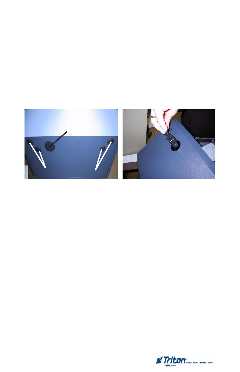
2. Locate the mounting holes on the top of the ATM cabinet, as shown in
Figure 1. Note that dome plugs cover the openings.
Power Cord Access
Mounting Holes
Figure 1. Location of topper access
and mounting holes.
3. Unlock and open the ATM control panel.
4. Remove the dome plugs from the top of the ATM cabinet to uncover the
topper cable access and mounting holes.
5 . If the topper power cord will be routed internally (normally), feed the power
cord (AC or DC) into the large access hole, as shown in Figure 2.
6. Place the topper assembly on top of the cabinet, ensuring that the topper
mounting studs are inserted into the corresponding holes in the cabinet, as
shown in Figures 3 and 4.
Note: Because of the slotted configuration of the mounting holes, there will be
some play (front-to-back) in the position of the topper assembly. Allow the
assembly to slide back until it stops.
Figure 2. Feed topper power cord
through cabinet access hole.
3
Page 4

LIGHTED LOWTOPPER - FIELD INSTALLATION GUIDE
Figure 4. Topper on cabinet. Note
location of mounting studs.
Figure 3. Place topper on cabinet.
Slide topper back until it stops.
7. Obtain four #8-32 nuts from the accessory bag. Place the nuts on the
mounting studs and tighten using a 3/8" nut driver to secure the topper
assembly to the cabinet, as shown in Figure 5 (below).
8. Insert the included snap bushing into the hole, as shown in Figure 6.
Figure 5. Place nuts on topper
mounting studs and tighten down.
Figure 6. Place snap bushing in access
hole.
4
Page 5

LIGHTED LOWTOPPER - FIELD INSTALLATION GUIDE
9 . Connect the topper power cord. Ensure the ATM power switch is turned
OFF before connecting!
DC CONNECTIONS (LED-LIT TOPPER)
Plug the DC power cord (molex connector) from the topper into any available DC
output connector on the power supply (*see Notes) as shown in Figures 7a-7e.
1
Note: The dispensing mechanism uses the largest molex connection on the
power supply.
2
Note: Model RL5000XP only. The DC power cord may be an 8-pin or 2-pin
molex connector . The 8-pin connects to the power supply and the 2-pin connects
to the GPIO board assembly. Figure 7f show the GPIO connection point.
3
Note: Model 9100 w/TDM or Minimech dispensers. The DC power cord
requires a power extension adapter (included). Figure 7g and 7h show the
connection points.
Figure 7a. Model 9100 (w/SDD)
Figure 7c. Model RL5000 (X-Scale)
Figure 7b. Model 97XX
Figure 7d. Model 8100
5
Page 6

LIGHTED LOWTOPPER - FIELD INSTALLATION GUIDE
Figure 7e. Model RL5000 (XP)
GPIO assy
Figure 7f. 2Note: Model RL5000 (XP)
3
Note: 9100 w/TDM or Minimech - Locate the Power Extension cable (splitter)
included in kit (Figure below). The cables connectors are marked. Disconnect
the Main boards power input (Figure 7g) and connect to one leg of the extension
cable. Connect the toppers DC power cable to the other leg (Figure 7h).
Reconnect this power cable assembly back to the main board. Figure 7i shows
the power assembly diagram.
Power extension cable (splitter).
6
Page 7

LIGHTED LOWTOPPER - FIELD INSTALLATION GUIDE
Figure 7g. Main board power
disconnected.
LED T opper
Power Supply
Figure 7i. Power extension cable configuration.
10 . Turn the power supply to ON (I). The topper sign should light up. Close and
lock the control panel.
Figure 7h. Power extension cable with
topper and main board power cables
connected.
Main Board
7
Page 8

LIGHTED LOWTOPPER - FIELD INSTALLATION GUIDE
AC CONNECTIONS (BALLAST/BULB TOPPER)
Plug the AC power cord into the A TMs power supply, as shown in Figures 8a
-8c.
Figure 8a. Model 9100
Figure 8c. Model RL5000
Figure 8b. Model 97XX
CONNECTING THE TOPPER POWER CORD FOR EXTERNAL ROUTING
(AC ASSEMBLY ONLY)
1. Lay the topper assembly on a flat
surface, rear side up, as shown in
Figure 1. Note the location of the
dome plug. You will remove this
plug in a later step, to allow the
power cord to be routed out the
back panel of the topper assembly .
Dome Plug
2. Remove the screws that hold the
front and rear panels of the
assembly together . See location of
screws in Figure 1.
Figure 1. Rear panel of topper
assembly, showing location of screws
and dome plug.
8
Page 9

LIGHTED LOWTOPPER - FIELD INSTALLATION GUIDE
3 . Carefully flip the entire assembly
over, so that the front side is up.
Lift the front of the topper
assembly away from the rear half.
It may be necessary to tilt the panel
to clear the four mounting studs.
4. Press in on the locking tabs to
release the dome plug and remove
the plug from the rear panel. Feed
the power cord through this hole,
as shown in Figure 2.
5 . Obtain the snap bushing from the
accessory kit. Insert the snap
bushing into the hole, as shown
in Figure 3.
6. Place the front panel back on to
the rear half. Secure the two
halves together, using the screws
removed in Step 2.
Figure 2. Route power cord through
rear panel access hole.
7. After installing the topper
assembly according to the
instructions on Pages 2 through
4, the power cable will extend from
the rear panel of the topper, as
shown in Figure 4.
8 . Plug the power cord into a facility
outlet. The topper sign should
light up.
Figure 3. Insert snap bushing into
access hole on topper rear panel.
Figure 4. Topper power cable,
routed externally.
9
Page 10

LIGHTED LOWTOPPER - FIELD INSTALLATION GUIDE
Instructions for Checking the T opper Light Bulb
(AC powered topper only!)
1. Lay the topper on a flat surface, rear side up, as shown in Figure 1.
Remove the screws that hold the front and rear panels of the assembly
together.
2 . Carefully flip the entire assembly over , as shown in Figure 2 , so that the
sign panel is up. Lift the sign panel up and away from the rear half. It may
be necessary to tilt the panel to clear the four mounting studs.
Mounting studs
Figure 1. Rear panel of topper
assembly, showing location of screws.
3. Locate the light bulb (see Figure 3). The best way to ensure the bulb is
firmly seated in the socket is to carefully remove and then reseat the bulb.
Note: If the bulb is bad, carefully remove the existing bulb and replace with a
new bulb.
4. Reinstall the topper front panel.
Flip the chassis over and attach
the two halves using the screws
removed in Step 2.
Figure 2. Turn sign face up to remove
sign panel.
Figure 3. Location of light bulb.
10
 Loading...