

Page 1
TERMS AND SYMBOLS USED IN THIS MANUAL
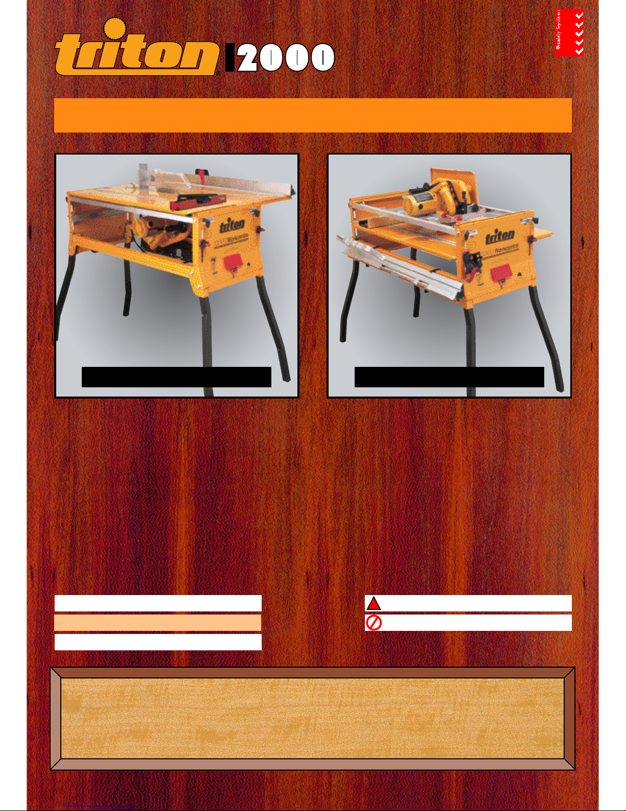
“Front of the Workcentre” refers to the end which has the switchbox. The “left-hand &
right-hand side” are when viewed from the front of the Workcentre.
Safety warning or safety instruction.
Handy hint & tip.
Possible fitting or operating difficulty.
Assembly & Operating Manual
A WORD FROM THE MANUFACTURERS
Thank you for your purchase of the Triton Series 2000 Workcentre. If properly set up,
and fitted with a good quality saw and blade, it will give you great accuracy and many
years of trouble-free service.
To set up properly, make sure you follow this manual. Otherwise you could spend
many unnecessary hours, and still not get it right.
Workcentre
Quality
Endorsed
Company
TABLESAW MODE
CROSSCUT MODE
Parts list 2 Test Cuts - Table saw mode 12-13
Basic assembly diagram 3 Test Cuts - Crosscut mode 13-14
Fitting the Triton Precision Saw
4-5 Operating - Table saw 15-23
Fitting other brands of saw 6-7 Operating - Crosscut saw 24-27
Final assembly 8-11 Warranty & Mailing List 28
SERIES
Workcentre
SERIES
Take special note of this instruction.
WARNING! Do not attempt this.
!
Page 2
Page 2
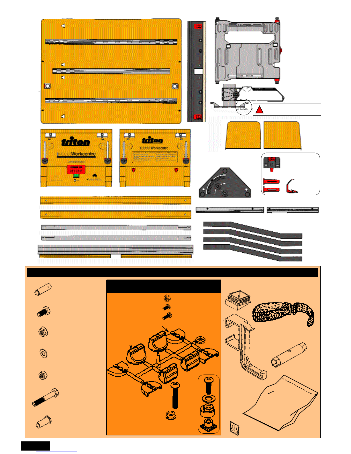
PARTS LIST
k. Saw Locators (4)
d. 8mm Washer (20)
m. M6 x 40mm Philips-
head Screws (4)
n. M6 Flange Nuts (4)
a. Leg Locking Pin (4)
b. M8 x 16 Bolt (4)
c. M8 Flange Nut (4)
e. M8 Nyloc Nut (8)
f.
M8 x 50 Bolt (8)
s. Tube Spanner
q. Trigger Strap
u. Scale
Pointer Labels (1)
r. Fence Hanger (2)
g. Push-stick
hanger (2)
p. Angled foot (4)
h. M5 Nyloc Nut (3)
j. M5 x 25 Screw (1)
o. Alignment Cams for Triton Saw
(2 sets packed in separate bag)
A Table (1)
C Rear End Panel (1)
D Legs (4)
E Bearing Channels (2)
F Base Channels (2)
G Protractor (Mitre gauge) (1)
H Crosscut
Fence (1)
I Rip Fence (1)
J Overhead Guard &
Guard Support (1)
K Side Guard (2 parts)
L Slide Chassis (1)
M Guided
Push-stick &
Side Pressure
Finger Kit (1)
N Rip Fence Bevel Guides (3 parts)
MAIN FASTENER BAG
Router Table
Series 2000
Fitting Kit
B Front End Panel (1)
t. Router Table
Fitting Kit
l. Clamping
Knobs (4)
Reverse from packed
position before using
!
SAW CLAMPING HARDWARE
(SEPARATE BAG)
i. M5 x 8 Screw (2)
N Rip Fence Bevel Guides (2 parts)
Page 3
Page 3
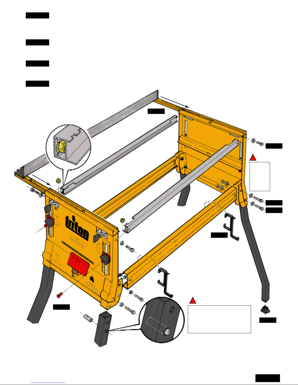
Insert Flange Nuts into
the ends of the
bearing channels.
Check that each leg and leg
locking pin is facing the right
way before fitting. Depress
and hold the spring-loaded
ball when fitting the leg.
!
!
Note the
correct
positions
for the
washers.
STEP 1: Fit the Legs (D) to each End Panel (B & C). Before fitting, check that each leg splays
outwards as shown, and that you have fitted the Leg Locking Pin (a) with the springloaded ball facing outwards. Tighten the bolts so that the legs are firm, but still free to
pivot. Use four M8 x 50 bolts (f), eight washers (d) and four M8 Nyloc nuts (e).
STEP 2: Fit the Base Channels (F) as shown. Tighten the bolts until the leg brackets close firmly
on the base channels. Do not overtighten. The Nyloc nuts used are vibration proof and
won’t come undone. Use four M8 x 50 bolts, eight washers and four Nyloc nuts.
STEP 3: Fit the Flange Nuts (c) inside the Bearing Channels (E) and fit the bearing channels to the
end panels. They should click into position when pushed up from below. Fully tighten the
bolts. Use four M8 x 16 bolts (b), four 8mm washers (d) and four flange nuts.
STEP 4: Fit the plastic components (r, g & p) as shown, and then fit the Rip Fence (I).
(r)
(g)
STEP 1
STEP 3
STEP 2
STEP 4
(p)
STEP 4
STEP 4
STEP 4
FENCE LOCKING: You only need use 2 locking levers - one at the front and one at the back. The
locking position of the levers is factory preset. To adjust, simply loosen or tighten the nut at the
bottom of each clamp assembly. The levers should reach at least the half way point in their arc of
travel before tightening up. Lubricate the cam faces occasionally with light machine oil.
(I)
(E)
(F)
(D)
(c)
(b & d)
(a)
(B)
(C)
(d & f)
(e)
Page 4
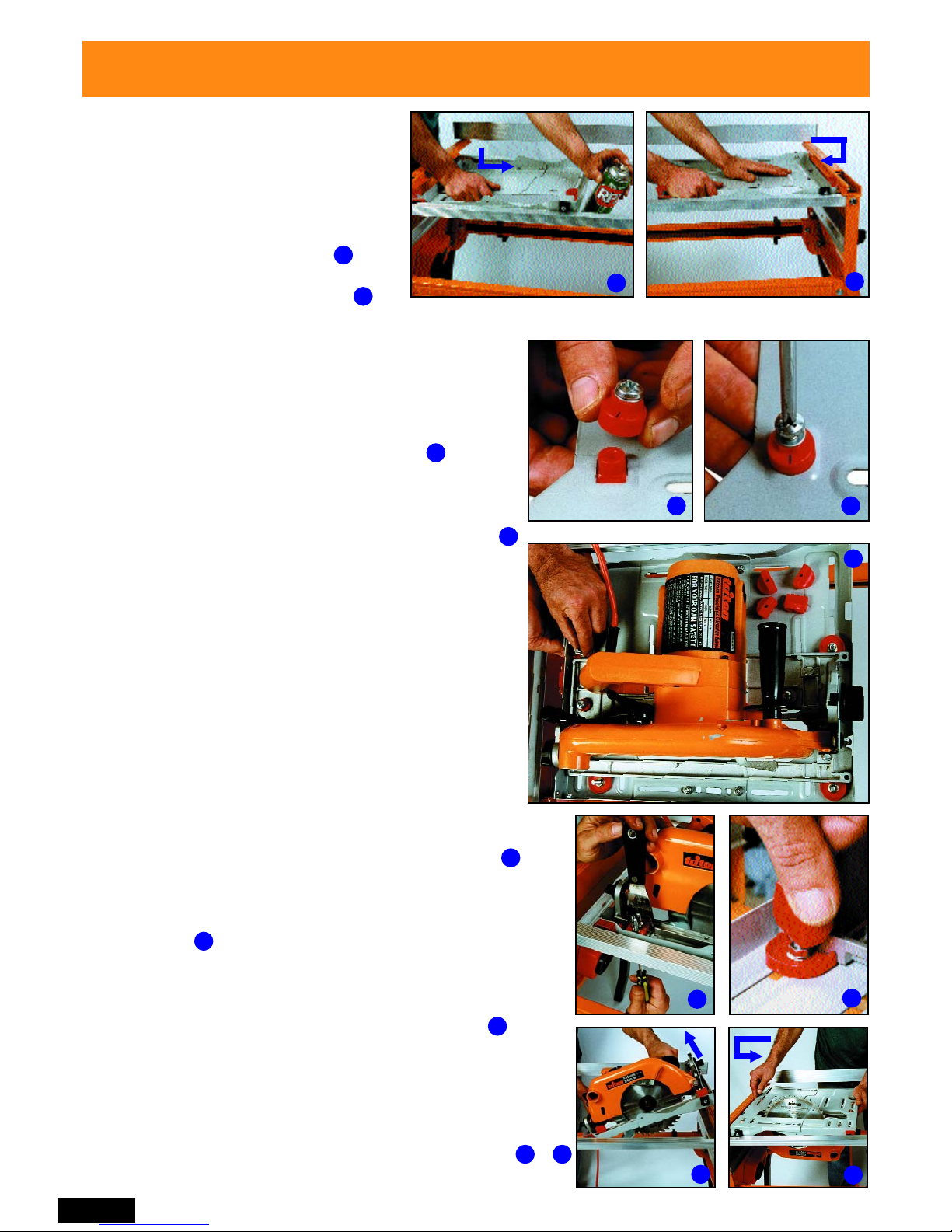
1
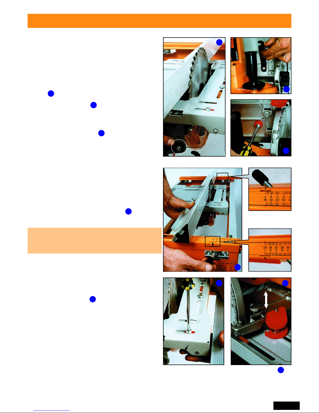
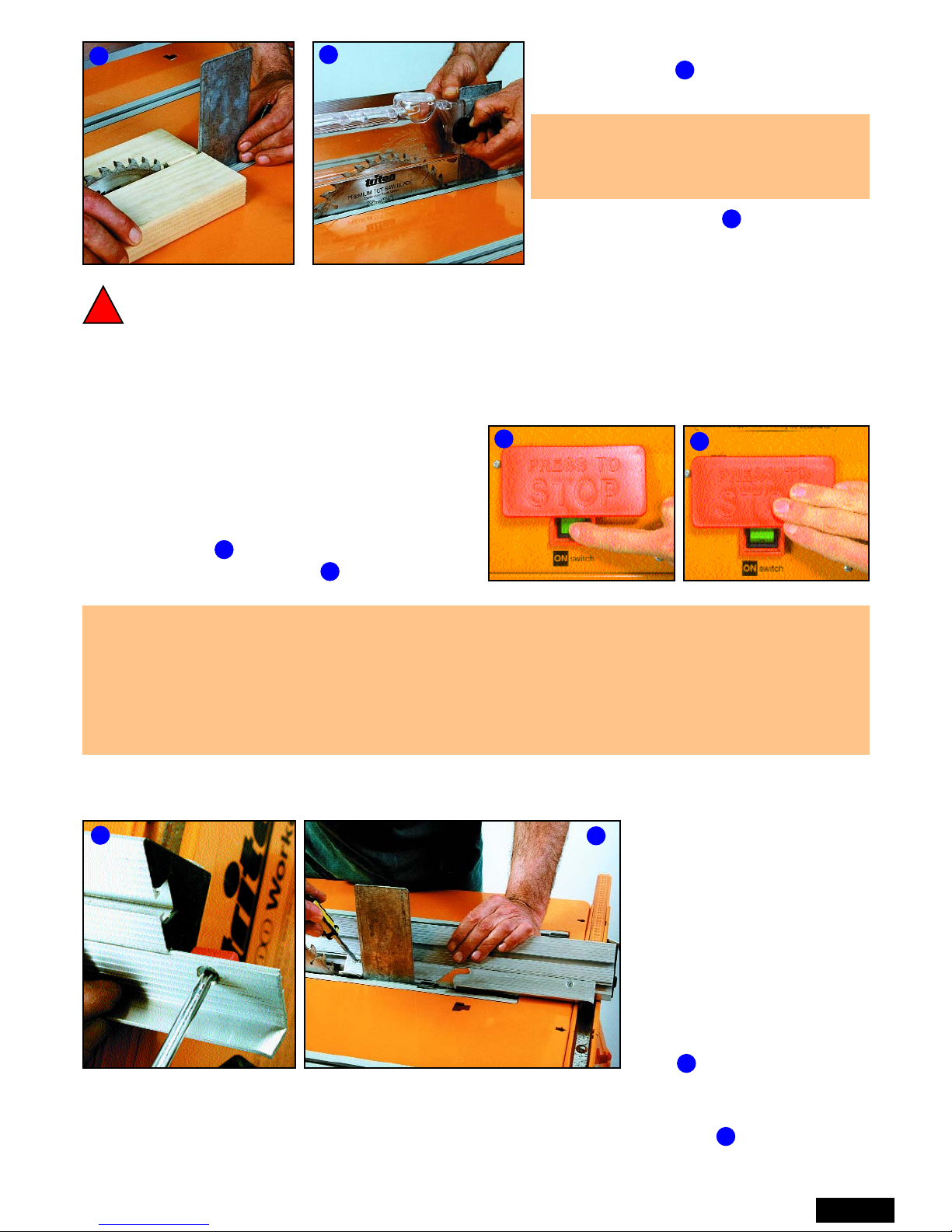
Unplug your saw. Check that the blade is set at 0˚ and
at full depth of cut.
2
Page 4
Screw the knobs on (they cut their own thread) until they just
scrape against the top edge of the saw base-plate. This
tension is sufficient to hold the saw upside-down for final
adjustment, and still allow the saw to be shifted sideways
slightly using the alignment cams.
Fitting the Triton 235mm Precision Power Saw
For other brands of saw go to Page 6.
FITTING THE SLIDE CHASSIS
FITTING THE TRITON SAW
Spray the channels with RP7 or WD40 for a smooth slide.
Fit the saw into the chassis with the alignment cams
locating in the holes in the saw base-plate.
If the saw is set at full depth, the saw’s spring-loaded
guard will be held in the retracted position by the back
edge of the chassis cutout.
Break or cut the Saw Locators (k) and Knobs (l) from their
moulding “tree” and carefully trim off any remnants with a
sharp knife. Fit the saw locators in the slots shown in using
4 Philips-head screws (m) and Flange nuts (n). The straight
edges should be against the baseplate, but spaced away
from it slightly to allow for final saw adjustment. (Use a
spatula blade or a piece of cardboard or metal about 1
mm thick as a spacer.) Firmly tighten the screws.
FITTING THE SAW LOCATORS AND KNOBS
2
3 4
5
6
8
7
9
Place the Slide Chassis (L) in the
bearing channels with the red plastic
catch and red bearing spacers closest
to the front panel (the switch box end)
and the flanges upwards. Enter two
bearings in the channel cutouts.
Slide the chassis towards the rear panel
and the other bearings will drop in.
Fit the Saw Alignment Cams (o) from below , holding
the bases in the rectangular slots while you screw into
them. (They cut their own thread.) Make sure the lines
moulded on top of the cams are both pointing towards
the rear panel. Tighten the screws until nipped gently.
Check that the saw is securely mounted. Turn the slide
chassis over, re-engaging the bearings in the channels. &
3
4
6
8 9
7
5
1
Page 5
6
5
When satisfied with the position of the saw,
reposition the saw locators hard up against the
edge of the baseplate, as follows. Hold each knob
against turning and loosen the screw about half to
one turn. Push the saw locator into position, and
firmly tighten the screw.
Turn the saw right-way up again and loosen the
four knobs a couple of turns. Check that the saw
cannot move sideways at all, and that all screws
are fully tightened. Do up the knobs again,
perhaps one turn beyond when they first scrape
on the baseplate.
The saw is now set up, and is available at any
time for hand-held use by simply loosening each knob half a turn and lifting the saw straight up.
If the locators are correctly fitted, the saw will go back into exactly the right spot each time.
Triton saw owners, please skip to Page 8.
4
Double-check the saw position by now locking the
fence at 0 mm, and trying to turn the blade
backwards by hand. The teeth should lightly
scrape against the face of the fence. If not,
repeat the above alignment.
3
2
1
This is a very important step, because it will
ensure that your saw cuts are true, and that your
fence scales are accurate, so take your time.
Page 5
Position the chassis halfway between the end
panels. Adjust the fence in close to the blade and
lock it. Make sure the blade is vertical by
comparing it to the face of the fence.If necessary,
loosen the nut holding the Blade Angle Trimmer
(circled), and adjust the blade angle. Re-tighten
the nut.
Use the saw’s spanner or the Tube Spanner
(s) to rotate the cams until the front and rear of
the blade are just touching the fence, when it is
at 0 mm. When satisfied with the position tighten
the alignment cam screws.
ALIGNING THE SAW
FINAL CLAMPING OF SAW
Fitting the Triton 235mm Precision Power Saw (cont.)
1
2
3
4
5 6
Hold knobs while
adjusting locators
Adjust
blade angle
Unscrew the front handle of the saw for better
access to the front cam. Lower the blade for
access to the rear one.
Page 6
2
4
Break or cut the Saw Locators (k) and Knobs (l) off their
moulding “tree”, and trim any remnants with a utility knife.
Fit the saw locators in the selected slots, with their straight
edges against the base-plate using four M6 screws (m) and
Flange nuts (n). Firmly tighten up the screws using a
screwdriver from below.
The spanner shown is optional, as the Flange nuts are self-gripping.
76
5
Check that your saw is unplugged, make sure the blade is set at full depth of cut, and is set at 0˚.
Study below [especially if you have a small (184mm) saw] and follow steps 1 to 5 as required.
Page 6
Fitting other brands of power saw
FITTING THE SAW LOCATORS
Check that the saw is securely clamped, and
turn the slide chassis over, re-engaging the
bearings in the channels. &
FITTING THE CLAMPING KNOBS
Screw the knobs on (they cut their own thread)
until they scrape against the top edge of the
saw base-plate. Leave the knobs with the
cutaway sections facing away from the saw.
5
6 7
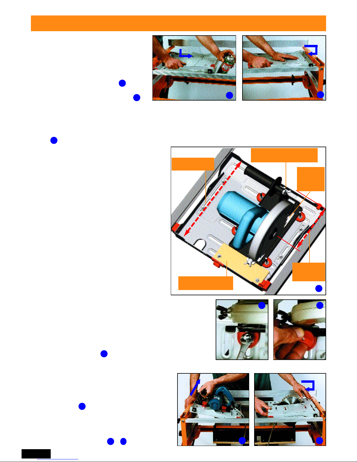
ADJUSTING THE SLIDE CHASSIS
1. Adjust the slide chassis to the shortest
length which will suit your saw, and provide
widely spaced slot positions on the
baseplate edges for fitting the clamps. (In
shortening the chassis, do not overlap any of
the mounting slots. If relocating the four
coach bolts, use the square holes.)
2. Position the saw as far forward as possible
on the chassis, but allow for finger access to
the front wing-nut or knob on the saw.
3. Don’t obstruct the sawdust opening in front
of the saw blade.
4. Try to have the blade nut no more than
170mm from the front of the chassis.
5. For small saws, bolt a thin wooden spacer
(eg. 6mm ply) behind the saw, to prevent
possible saw movement.
3
1. Adjust chassis
to length
2. Saw forward in chassis.
Allow access to adjuster.
4. Maximum
distance
170mm
5. Attach 6mm spacer
for small saws
3
3. Don’t
obstruct
sawdust
opening
1
FITTING THE SLIDE CHASSIS
Spray the channels with RP7 or WD40 for a smooth slide.
2
Place the Slide Chassis (L) in the
bearing channels with the red plastic
catch and red bearing spacers closest to
the front panel (the switch box end) and
the flanges upwards. Enter two bearings
in the cutouts in the channels. Slide
the chassis towards the rear panel and
the other two bearings will drop in.
1
4
Page 7
Do up the knobs, and this time you can tighten them a little
more firmly, perhaps one turn beyond when they first scrape on
scrape on the base-plate.
If you tighten any one knob too much, and can’t loosen it, undo
the other three knobs by half a turn, remove the saw and undo
the knob.
Page 7
Fitting other brands of power saw (cont.)
Have the chassis midway between the end panels and lock the rip
fence close to the blade. Compare the blade angle to the vertical
face of the fence, and if necessary adjust the blade angle (using
the saw’s adjuster) until they are parallel vertically.
Hold the clamping knobs to stop them turning and use a
screwdriver to loosen the clamp assemblies - half to one turn only.
Push the saw locators to move the saw. Do not push the saw
itself as this may dislodge the clamps.
Lock the fence at “0” front and rear and align the saw so that the blade is just touching the fence.
Spin the blade backwards by hand. The teeth should lightly scrape against the fence.
ALIGNING THE SAW
This is a very important step, it will ensure that your saw cuts are true, and that your fence
scales are accurate, so take your time.
!
The saw is now set up, and is available at any time for handheld use by loosening the knobs half a turn and lifting the saw
straight up. If the locators are correctly fitted, the saw will go
back into exactly the same position each time.
1
2
1
2
Turn the saw upside down again, re-fit the fence and double
check that the blade is still at “0”.
Push saw locator
not the saw
FINAL CLAMPING OF SAW
3
4
4
3
Check that each saw locator is pressed up against
the baseplate, hold the knobs against turning, and
firmly tighten the four screws.
Remove the fence and turn the saw rightway up.
Undo the clamping knobs a couple of turns and
check that you cannot move the saw sideways at
all between the locators.
Blade just
scrapes
fence at “0”
Page 8
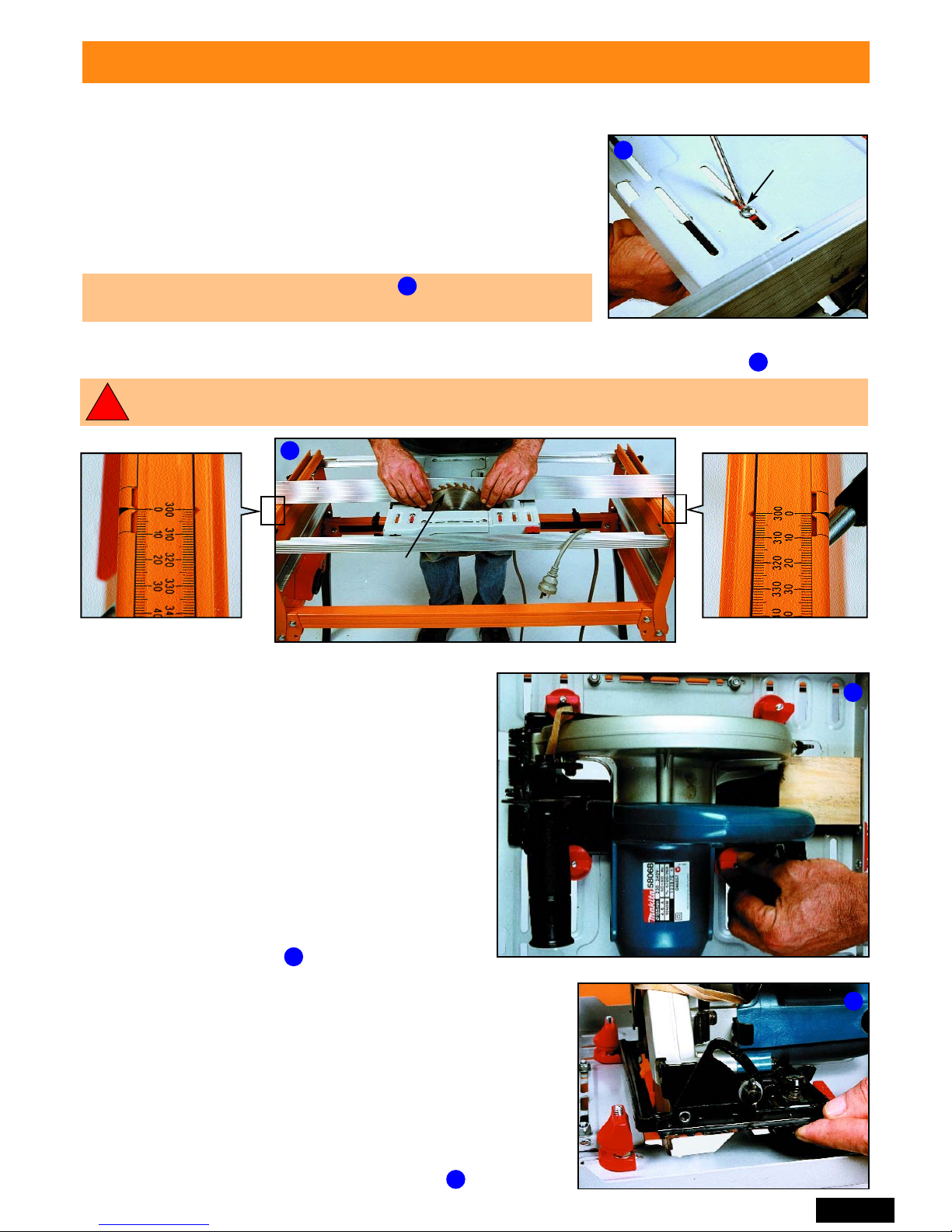
FITTING THE OVERHEAD GUARD & SUPPORT
Loosen the knob on the Overhead Guard (J) to remove the
Guard Support from its shipping position. Fit the support to
the centre table slot, using the cut-outs at the end.Ensure the
saw blade is adjusted to its maximum depth, then position
the support about 12mm behind the blade and lock it in by
pressing the locking lever down.
Lubricate the entry if it’s a tight fit. Check the guard support
is reasonably square to the table, and adjust it if necessary
by pushing evenly with your hand or a block of wood.
Page 8
Wrap the Trigger Strap (q) around the handgrip with
the furry side facing outwards. Pass the strap through
the buckle, until the security loop has passed through.
If your saw has a safety lock-out button press it and
then tighten the strap until the trigger clicks “ON”.
Wrap the free end of the strap around the handgrip.
With most saws, the strap can be slid on and off the
saw trigger, without undoing it each time.
Turn the slide chassis upside down. Position it roughly half-way between the end panels. The front
of the saw must be facing the front panel (switchbox end).
Lower the Table (A) over the blade, with the four T-slots closest to the rear panel. Line up the
arrows on the edges of the table with the scale pointers on top of the end panels. Push the table
latches to the “LOCK” position. The red indicators disappear from view when the latches fully locate.
Reach underneath and push the slide chassis towards the rear panel until the red catch (shown in
the inset view on ) “clicks” home and locks the chassis underneath the table.
LOCKED
UNLOCKED
FITTING THE TABLE
!
Before fitting the trigger strap (q) always ensure that the saw is disconnected from the power
and that the switch on the Workcentre front panel is in the “OFF” position.
FITTING THE TRIGGER STRAP
T-slots to rear
FITTING THE SIDE GUARD
Slide the two sections of the Side Guard (K) together until they fit
between the pivot brackets on the slide chassis. Loosely fit the short
Philips-head screw (i) and a Nyloc nut (h) to hold them together.
Fit the two longer Philips-head screws (j) and Nyloc nuts through the
pivot brackets and into the guard flanges. Tighten until the guard
is firm, but still free to pivot. Finally, tighten the screw holding the
two halves together.
Nyloc nut
on inside
1
2
3
4
5
6 7
1
2
3
4
5
6
7
Do not leave the trigger strap permanently locked on. When you have finished work for the day,
release the strap and allow the spring in the trigger to relax.
Page 9
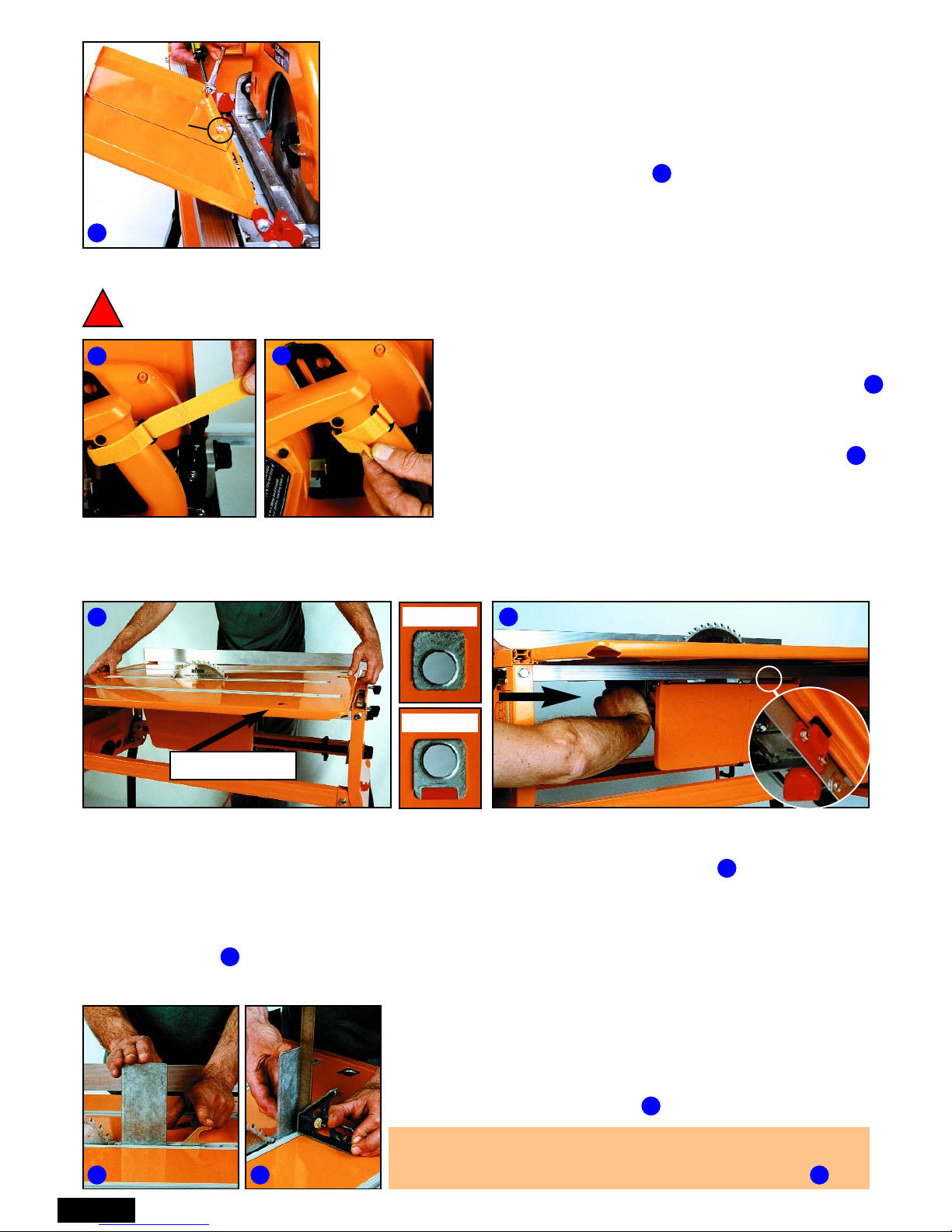
The plain bevel guide fits in front of the blade. The notched bevel guide fits at the rear, with the
small tab locating between the blade and the overhead guard support. (If your power saw is fitted
with a riving knife remove the small tab (circled) from the guide using a hacksaw.)
Tighten the Phillips head screws. The function of the guides is described on 20.
Hold 2 straight pieces of wood lightly
against the blade. The overhead guard
support should fit between the pieces.
Fit and lower the guard. Spin the blade
by hand before connecting the power to
ensure it is not touching anything.
If not you may have to adjust the saw
position slightly. This is only likely if you
have a very thin kerf blade (2.0 - 2.2mm
cut width)
Page 9
CONNECTING THE POWER
Make sure the switch is “OFF”, plug the saw into
the switch box, and bring power to the switch box
via a 10 Amp extension cord.
Press the green switch with your finger to switch
the power “ON”. Tap the stop plate with your
hand or knee to switch “OFF”.
Switch the power on and off and watch the blade. If it quivers sideways on start-up it’s a sign of a
worn arbor in your saw, or excessive slack in the mountings between the motor and baseplate.
If the blade vibrates significantly at full speed or on slow-down, it’s either buckled or not seated
properly on the arbor. Check the flatness of the blade with a straightedge, check the fit of any
arbor-reducing washers, and check for resin/sawdust build-up on the arbor or flange washers.
A slight quiver is generally noticeable on slow-down in most blades, and shouldn’t affect your cuts.
Always make sure the blade is at full height, the guard is fitted, and the table is locked to the
end panels before switching on the power.
Check that the teeth on your blade are pointing in the same direction as the etched symbols
on the guard. If not, you have incorrectly fitted the blade to your saw.
!
Reverse the fence so that
when fitted to the Workcentre
from the left hand side, the 45
o
face is closest to the blade.
To fit the Bevel Guides (N),
loosen the Phillips-head
screws slightly, engage the lip
at the top of each guide in the
mating section of the rip
fence, and guide the red
plastic clamping feet into the
T-slot.
1
2
3
4
5
6
1
2
5
6
3
4
FITTING THE BEVEL GUIDES
Page 10

Page 10
Always make sure that all four bearings are
back inside the channels before making a cut.
!
The fence may be a little tight - especially when new. Do not loosen the screws fastening the four
plastic feet. Rather use a block of wood to gently tap the fence home. If you do have to loosen the
screws,
1
/4to 1/2a turn should be enough. The plastic feet are difficult to re-seat if undone.
The four most common saw sizes are printed on the end panels for reference. In the table
height is being set for a 235 mm (9 1/4”) saw. The top edge of the red indicator is the reference.
Turn the saw right way up but leave two of the
bearings on top of the channels. Slide the table
in from the side until the centre slot is directly
below the blade. Lock the table by pushing the
latches fully home into the cut outs in the table
support rails. (The red indicators on the latches
must fully disappear from view).
Slide the chassis to the rear panel and the two free
bearings will drop into the channels.
The rails are meant to be a snug fit inside the panels and may
need a sharp tap to free them. The adjustment is a bit easier
without the table in position.
Fit the Crosscut Fence (H) to the four Tslots in the table, with the MDF sub fence
closest to the saw. Pull the fence towards
the rear panel as far as it will go.
To release the fence, hold down each red
plastic catch while pushing the fence
towards the saw.
The tip of your blade should be just entering the
slot (by 1 - 2 mm) and it should be approximately
central in the aluminium track. If not, see Saw
Slump adjustment on Page 13.
Leaving two bearings out of the channels enables you to slide the table in from the side without the
tip of the blade scratching the paintwork on the table. Another method is to raise the saw blade a
little, and then lower it again when the table is in position.
FITTING THE CROSSCUT FENCE
1
3
4
SETTING UP THE CROSSCUT MODE
Remove the overhead guard and rip fence and store them as
shown on Page 28.
Remove the table and place it to one side for the moment.
Adjust the height of the aluminium table support rails inside the
front and rear panels, to suit your saw.
1
1
2
3
4
5
2
5
Page 11

The Guided Pushstick slides in the
T-slot on the 45˚ face of the rip
fence. The swing-arm rests against
the vertical face, and should pivot
freely.
The lock direction of the swing-arm
can be reversed (depending on
which side of the Workcentre the
rip fence is used) by firmly pressing
the direction switch.
Clip the Side Pressure Finger to the holder, noting the correct orientation of the bulge . Snap the
assembly into the left-hand corner of the protractor. Pull the finger out to lock. Press the trigger and
push the finger in to retract.
In use, the finger is extended and the protractor locked at an appropriate angle to press the wood
against the fence in front of the blade. The protractor must be locked in it’s slot by loosening the
locking knob, rotating the pointer to the position, and re-tightening. (See also Page 12)
A spare finger is included in case you accidentally cut one.
Page 11
Set on the left of the blade, the fence gives the maximum 620mm capacity.
However, if you prefer to use the fence on the right, the self-adhesive
Scale Pointer Labels (u), will provide the zero position.
Fit the fence on the right and touch it against the blade. Check it is exactly
parallel by comparing the readings at the front and rear panels - about
183mm / 483mm. Lock the fence, turn the blade backwards by hand and
the teeth should lightly skim the fence.
Remove all dust, and apply the labels to the specified end panels directly
in line with the 0 marks on the scale arms.
The labels wrap inside the tracks to prevent peeling off. Lines printed on
the labels show where to fold. Once they’re stuck in position, slide the
fence away to fold the tops of the labels inside.
The edges of the pointer cutout, and the two fine 0.5 lines are 9.5mm from the arrow-point. Use
them as a vernier in setting 0.5 mm increments, to avoid guessing the mid-point between
graduations.
USING THE RIP FENCE SCALES
USING THE RIP FENCE ON THE RIGHT
You can reverse the bolt and knob in the overhead guard for closer fence
access if using the fence on the right.
2
3
2
3
FITTING THE GUIDED PUSHSTICK AND SIDE PRESSURE FINGER
4
5
Direction switch
Note direction
of bulge
4
Trigger
5
1
Each end panel has two scale pointers exactly 300 mm apart. For cuts in
the range 0 - 320, (with the fence on the left of the blade) use the pointers
which are closer to the blade. Line up the arrow point and read the lesser
figure on the scale arms.
For wider ripping in the range 320 - 620mm simply move across to the
outer scale pointers and read the higher figure.
In , the fence is set at 100mm using the 0-320 mm pointers. It would be
400 mm if you were using the outer pointers.
1
6
Page 12

Page 12
TEST CUTS - Tablesaw Mode
It’s important that you perform these test cuts, in the
order laid out in these two pages.
First, check your square - many are inaccurate. Use a
board with a straight edge. Press the square firmly
against it, and use a sharp pencil to trace the blade on
the board. Flip the square over, press it against the
straight edge again, and compare the blade to the pencil
line. Any error in your square is seen as doubled.
Fit the protractor to the left or right table slot, and
check that it slides freely from end to end. Spray
lubricant such as RP7 on the slider strip. Set the
protractor at exactly 0
O
, and tighten both knobs.
Hold the wood firmly against the long sand-paper
face of the protractor, and push the protractor down
lightly for best guidance in the slot. Feed the
wood smoothly into the blade.
When the workpiece is past the back of the blade,
switch off by bumping the STOP plate.
CROSSCUTTING TEST
Take a straight piece of wood 30 - 45 mm thick and at least 300mm long. Lower the overhead
guard to about 5mm above it.
If the back of the blade re-cuts or burns the workpiece, your saw is probably slightly skew on the
slide chassis, and may have to be adjusted slightly. Or your blade could be buckled.
For an error ALONG the cut, re-adjust the
protractor angle slightly and repeat the test.
(Hold the square against the edge that was
against the protractor face).
For an error ACROSS the cut (with the
square against the face which was on the
table) adjust the blade angle slightly.
CHECKING THE CUT
If your saw does not allow you to get the blade completely square to the table, either file out the
curved slot in the saw’s quadrant, or attach shim packing between the narrow edge of the saw
baseplate and the slide chassis to angle the whole saw slightly. The Triton Saw Stabilising Bracket
(see next page) is advised if the blade reaches 90˚, but then slumps away because of saw flex.
Take a straight piece of wood at least 70mm wide and 500mm
long, and adjust the overhead guard to about 5mm above it.
Lock the rip fence exactly parallel to the blade at a fence
setting to give an off-cut of say 5 mm.
Fit the guided push stick and side pressure finger as shown
in . The protractor must be locked in the slot (as circled)
about 20mm in front of the blade, and at an angle to gently
flex the finger. Avoid applying too much pressure.
Hold the wood firmly down on the table and feed it smoothly.
Keep pushing it - without pausing - until it is fully past the back
of the blade. Use your hands while it is safe to do so, but finish
off using the guided push-stick to push the wood through.
RIPPING TEST
2
3
4 5
6
1
2
3
4
5
1
Protractor
locked
6
Page 13

Unlock the trigger strap and use the trigger
normally. With the power off, push the saw from
end to end, to check that the blade tip is clear of
the table slot.
Take a straight piece of wood, at least 300 mm
long, hold it with your right hand, and push the saw
with your left. Hold the wood firmly, pushing it
down on the table and against the fence. Check the
blade is not touching the wood before switching on.
Gently and smoothly make the cut, without forcing
the saw. If you have to push hard, or if there’s a
burning smell, sharpen or replace the blade.
Page 13
If the back of the blade re-cuts or burns the workpiece, either the fence was not parallel, or the saw
needs adjustment on the slide chassis, or the blade is buckled.
If the wood tightens up between the overhead guard support and the fence, switch off and wait until
the blade stops before withdrawing the piece. Increase the rear fence setting slightly and repeat the
cut. An extra 0.5-1mm on the rear fence settings is okay to prevent jamming.
TEST CUTS - Crosscut Mode
Avoid pulling a spinning blade back towards you.
The offcut - especially a small one - could be re-cut
by the back of the blade, with a bang!
1. Build a compensating angle into the table
position, so that the table remains square to the
blade. In , the table support rails are set at
72mm on one side, and 80mm on the other.
2. Obtain the Triton Saw Stabilising Bracket
(ABA020) which provides a strong brace for the
motor, yet still allows easy blade height and
angle adjustments;
3. Upgrade to a saw with better motor mounts;
4. Adjust the blade angle slightly every time you
convert between modes.
If there’s a step in the cut , or a high spot or a
burn mark, see Arbor float on Page 14.
If the blade marks the work piece as it is slowing down, simply pull the wood out sideways once
you’ve cut through.
1
2
3
1
2
3
72mm
80mm
Remove any uncut fibres, and check for accuracy as described earlier.
For an error ALONG the cut, check that the fence was fully home in the T-slots and that there was
no sawdust between the wood and the fence. Always hold the square against the edge that was
against the fence.
For an error ACROSS the cut, you probably have some “saw slump”, or flex between the saw motor
and its baseplate. You have four options to rectify the problem:
If you can’t complete your cut, because the blade tip doesn’t quite reach the crosscut fence, either raise
the table slightly, or move the saw slightly forward on the slide chassis, or pack out the MDF subfence.
Adjust table square
to the blade
Page 14

ARBOR FLOAT
Page 14
A float-free arbor, and firm mountings between the motor and baseplate, are most important.
Check for arbor float as described above. To check the mountings, hold the baseplate down on a
flat surface, and see how much you can move the motor up and down. Test at different height and
angle settings.
Most circular saws have a height adjustment pivot at the front, with the locking lever/knob behind
the motor. They are the preferred type. Vertical lift (plunge-type) saws should only be fitted if they
remain rigid and accurate throughout their height and angle adjustment range.
A 235mm (9 1/4”) saw is best for heavy work, requiring a large depth of cut or extra power. 208mm
(8 1/4”) or 185mm (7 1/4”) saws are quite adequate. If considering upgrading your saw, the Triton
235mm Precision Power Saw is highly recommended.
SELECTING A SAW BLADE
This is one of the key factors for square, smooth cuts with a minimum of splintering. We strongly
recommend tungsten carbide tipped (TCT) blades.
Triton Premium TCT Saw Blades have been
expressly designed for the Workcentre and have a
unique tooth design. They cut very cleanly, reduce
arbor float-related problems, and minimise
splintering, especially in veneered boards.
The number of teeth depends on the work you’ll
mainly be doing: for crosscutting, the more teeth
the better. A 184mm saw should have 30 - 40 teeth
and a 235mm saw should have 40 - 60 teeth.
Ripping generally requires fewer teeth, (20 - 32 on a 235mm blade), with larger gullets behind the
teeth to help clear the longer curls of saw dust created when ripping natural timbers.
If you can only afford one blade, we suggest more teeth rather than fewer. Just slow down the feed
rate when ripping natural timbers.
Triton TCT Saw Blade Cut
Standard Saw Blade Cut
If your cuts have ridges, burn marks or high
spots , the saw is mounted skew on the
slide chassis, or it has arbor float, or the
blade is blunt / buckled. Check for arbor float
by unplugging, gripping the blade or blade
nut, and pulling in and out in the direction of
the shaft. Any movement is undesirable.
For perfectly square cuts, you may have to
repair or upgrade your saw.
You might reduce the problem by placing a
parallel-sided packer between your work and
the fence. Also try shaving cuts, where
the second (shaving) cut removes say 1 mm
of material, putting less load on the arbor.
SELECTING A CIRCULAR SAW
1 2
3 4
5
1
2
3
4
Packer
Page 15

Page 15
OPERATING - Tablesaw Mode
Always keep fingers well clear of the blade. Fit the
overhead guard as low as possible, to just allow the work to
pass under. Where possible use the guided pushstick and
side pressure finger.
Never reach over or behind a spinning blade. Most
accidents occur when reaching over an unguarded or
poorly guarded blade to remove off-cuts. Push off-cuts away
with a stick, or switch off and wait until the blade has
stopped spinning before removing them.
Always use the safety guard when through ripping.
Position the guard support at least 12mm behind the blade
at all times. The guard acts as a “splitter” and a “hold-down”,
to prevent the wood from flinging towards you. Lower the
guard so the anti-kickback fingers are lightly flexed.
Always use the rip fence or protractor. Never attempt a
freehand cut (e.g. following a pencil line). The blade can
fling the wood towards you with great force if you twist it
even slightly during the cut.
Always set the fence parallel to the blade, and lock it
securely at both ends. You must never angle the fence to
the blade for rip cuts. Your wood will jam against the
blade, and could be flung out towards you.
Always control the piece between the blade & fence.
If uncontrolled, this piece could get damaged by the side of
the blade, or be flung out towards you - especially with short
workpieces. Use the pushstick rather than your fingers,
unless you have good hand access between the fence and
the guard.
To rip a 70mm piece down to 60mm, it’s much safer and
more accurate to set the fence at 60mm, and have the offcut
fall harmlessly aside, than to set the fence at 7mm
(allowing for a 3mm saw cut) and have a narrow offcut
trapped between the blade and the fence.
Always wear eye & ear protection. Serious accidents
occur when operators get sawdust or chips in their eyes
during a cut. Use ear muffs, and a dust mask or a dust
collection system.
It is important that you practice the following safety rules at all times.
For generally smoother cuts with less splintering, lower the blade until it is just a few millimetres
through the work. You can further improve cut quality by ripping 1mm oversize, then resetting the
fence and making a finishing cut, putting less load on the saw and blade.
Anti-kickback finger
1
2
3
4
5
6
1
2
3
4
5
6
!
Page 16

RIPPING THICK WOOD
Double your maximum depth of cut by turning the wood
over, end for end, and making a second cut. If the edges
were dressed square, the two cuts should be in line.
The overhead guard cannot be fitted for the first cut.
Prevent the wood from riding up on the blade and feed
slowly. Be careful of your hand positions. They must stay
clear of the blade even if the wood kicks back. The guard
must be fitted for the second cut.
Page 16
Set the fence on the left, and lock it parallel, although you
can add between 0.5 - 1 mm to the rear fence setting for
clearance.
Lower the overhead guard as a “hold-down”, lightly flexing
the anti-kickback fingers. Push the work against the fence
with the left hand, and support the off-cut with your right.
Keep both hands on your work and switch off with your
knee when you finish the cut.
The Triton Multi-Stand is ideal for supporting larger
offcuts. You can clamp a length of wood in the head for
even better support.
For ripping very large sheets, consider the Triton Sliding
Extension Table (ETA200) or use the saw hand-held.
Remove it from the chassis, undo the trigger strap, and
check the saw guard. Clamp a guide to the workpiece,
which should be supported securely on packers.
When ripping thin, flexible material wider than around
500mm, you will need additional support, such as the
batten shown to stop the front corner of the material
becoming snagged by the rear fence arm.
Try to keep the workpiece moving, even slowly, during a long rip.
Pauses can cause slight steps in the cut. A finishing cut should help.
Set up the Workcentre on level ground, and kick the legs diagonally outward to ensure it is stable.
Check that it is correctly set up (as described on Page 12 Ripping Test).
RIPPING LONG PIECES
When ripping long pieces which will overhang the rear of the table
by more than half their length, either have a friend help you, or rig
up a “tail-out” support. The Triton Multi-Stand (MSA200) is ideal for
this as it will not steer the work away from the fence.
If using a conventional roller stand make sure it is exactly
perpendicular to the direction of feed, or it will steer your work.
1
2
3
4
Batten supports
flexible material
RIPPING LARGER SHEETS
Adjust the blade height so you’ll make two equal-depth cuts... eg. set it at 46mm for double ripping
90mm material
1
2
3
4
Page 17

EDGE REBATING
By lowering the saw blade and adjusting the fence, you can make a wide variety of rebates.
When cutting wood which is rectangular in profile always make the first cut with the wood on edge
and the second cut on the flat. Otherwise, if rebating narrow wood, the workpiece could end up
balancing unsafely on a narrow rebate after the second cut.
3
4
Page 17
If planing a face wider than your maximum depth
of cut, set up as described above, and make two
planing cuts, turning the workpiece over (end-forend) after the first cut. Use the side pressure finger
to hold the workpiece against the fence.
For planing a bowed workpiece, attach a straight piece of scrap to the bowed piece so it overhangs
one edge for the full length. (Use brads or strong double-sided tape). Run the scrap along the fence,
dressing one edge of the bowed piece straight. Remove the piece of scrap and then run the
straightened edge against the fence.
You will probably not be able to use the overhead
guard for the first cut. You must keep the
workpiece well controlled, and be very careful of
your hand positions. They must stay clear of the
blade even if the wood kicks back. The guard
must be fitted for the second cut.
Try to make both cuts of similar depth. i.e. plane a
90mm wide face with two cuts of around 46mm.
PLANING AN EDGE
A tungsten carbide tipped blade or a planer blade
can give an excellent finish on poorly dressed,
weather-stained or painted material. Measure the
workpiece - say 90mm wide - and set the fence
at 88 or 89mm, to remove 1 or 2mm.
Use the side pressure finger and guided pushstick to hold and control the workpiece, especially
when planing narrow pieces. Keep the blade as
low as possible. Try not to pause during the cut,
and do a finishing cut if desired at a slightly
narrower fence setting.
You cannot use the overhead guard on these cuts, so
make sure your hands stay clear of the blade, even if
the wood kicks back.
Most rebates create a narrow off-cut. You should
avoid trapping the off-cut between the blade and the
fence by doing the cut as shown in . If you do have
a narrow offcut between the blade and the fence, do
not stand directly in line with the blade. The off-cut
could be flung towards you at high speed.
1
2
3
4
1
2
4
Never attempt planing cuts which involve moving the fence very close (1-2mm) to the blade.
PLANING A WIDER FACE
Page 18

Study the previous section on Edge
Rebating. Make two identical rebates
from opposite faces of the workpiece,
leaving you with a central tongue.
Complete the tongue with the wood
lying down flat as shown in ,Page 17.
To make a matching groove, move the
fence outwards (by one blade width
from the tongue setting) and make two
cuts from the opposite faces.
Raise the blade 0.5mm before cutting the groove, to allow for glue and to ensure a tight joint.
Page 18
Always make the first two cuts into the narrower edge of the workpiece , and the two final cuts
with the workpiece lying down flat (as in on Page 17). Otherwise, your workpiece could be left
balancing unsafely on the narrow tongue after the final cuts.
To set the blade to a desired depth of cut,
mark it on a piece of wood. Lay the wood
beside the blade, leaving both hands free for
adjusting the saw. Or use the 2mm &
10mm calibration marks on the face of the rip
fence for setting blade height.
In the blade is set to 30mm, the third deep
groove up from the table. (These calibrations
are approximate only and should be verified by
a test cut on some scrap.)
Test fence and blade height settings on short off-cuts of the wood you’ll be using. If joining long
pieces (which might not be dead straight), make the test pieces a slightly loose fit. Otherwise you could
have problems cramping the job up tightly.
You cannot use the overhead guard so be very
careful with your hand positions.
50
40
10
20
30
60
If rebating or tongue & grooving very thin
boards, the workpiece could be unstable
standing on it’s narrow edge.
Attach a suitable height sub-fence to the rip
fence for extra vertical support. (Use strong
double-sided tape - 50mm carpetlaying tape is
ideal - or countersunk bolts and nuts by
removing the fence end caps.) If necessary
use a piece of ply or hardboard with a thin slot
in it for the blade. Securely tape it to the table
as a mask, and have the blade protruding as
little as possible.
1
2
3
4
5
1
2
4
4
3
5
TONGUE & GROOVING
EDGE WORK ON THIN MATERIAL
4
Page 19

To rip tapers, the workpiece must be angled by a guide
that travels parallel to the blade.
For short tapers (400-500mm long), you can use the
protractor as your guide. The right hand table slot can
be used for wider pieces. Hold the workpiece tightly
against the sandpaper face and down on the table.
Make sure the overhead guard is fitted and correctly
lowered, because your fingers will be passing quite
close to the blade.
The width of material you can handle is limited and you may have to attach a packer to the
protractor face to achieve a desired cutting line. The workpiece should be attached to the packer
(using double sided tape or mechanical fasteners). Or fit a rear pusher block to the packer.
For longer or wider tapers, use a thin piece of parallel-sided
scrap as your guide. Attach the workpiece at the desired
angle. Slide the scrap against the fence, which is set parallel
to the blade. If the scrap was cut to say 100mm wide, set the
fence at 100mm, to give good back-up support directly
beside the blade.
Use brads or strong double-sided tape to attach the
workpiece, or use countersunk bolts, wing-nuts, large
washers and offcuts to clamp it to the scrap as shown in .
Page 19
WORKING ON ENDGRAIN
Attach a straight, board (100-150mm wide and 25-35mm
thick) to the rip fence as described above.
Make a guided “rider”, using an offcut of the same board
with cleats on both sides to slide snugly along the top of
the board. Attach a pusher block to hold the
workpiece vertical as you push it over the blade. Or
clamp the workpiece to the pusher block.
If making splined right-angled joints or splined butt
joints , cut all pieces from opposite faces, without
changing the fence setting, to ensure the grooves line up.
When working with narrow wood, make sure the
workpiece cannot jam in the blade slot. Use a mask
taped to the table as in Edge Work on Thin Material,
Page 18.
NEVER ANGLE THE FENCE TO THE BLADE FOR TAPER RIPPING. Taper cuts cannot be made
in this way and are extremely dangerous if attempted.
Rehearse these cuts with the blade dropped below the table level, and the overhead guard removed,
to check your hand positions. Do not rely on the first few millimetres of track at either end of the table for
completely accurate guidance.
1
2 3
4
5
Workpiece
Scrap
5
4
1
2
3
Pusher
block
TAPER RIPPING
Page 20

Page 20
BEVEL RIPPING AT 45
O
Turn the rip fence around and turn the fence arms around so that
they enter the end panel tracks first. The 45˚ face of the rip fence
will now be facing the blade with the fence still on the left.
Fit the overhead guard support about 30-32mm behind the blade.
Move the fence in close to the blade and lock it at about 11mm.
Loosen the Phillips-head screws and adjust the bevel guides so
they give your workpiece maximum support in front of and
behind the blade, and behind the overhead guard support.
Fine-tune the fence settings to ensure that the left hand face of
the blade is exactly lined up with the internal bottom corner of
the guide. This is important for cutting to a perfect “feather” edge
without losing any width of workpiece.
Fit and adjust the guard so the workpiece can pass underneath.
If bevelling narrow pieces, the guides give no
support while the wood is alongside the blade.
Clamp a straight piece of wood squarely to the
workpiece, , and use it as a guide running along
the top of the fence to support the workpiece at all
times.
The Workcentre fence should only be used for cutting pieces of a
manageable size - up to say 300mm wide. For larger pieces either
obtain the optional Bevel Ripping Guide (BRA200) or use the saw
hand-held with the work supported on battens.
CHAMFERING AT 45
O
You can also use the guides for 45Ochamfering.
Retract the front guide, so that you can move the
fence outwards - say to a setting of 20mm. Lock it
exactly parallel.
Observe the above instructions regarding hand
positions and hold-down pressures. If chamfering
thick wood, adjust the front bevel guide all the way
in to give maximum support beside of the blade.
Make sure the blade is at full height and that the slide chassis is
locked underneath the table.
With the power disconnected, spin the blade by hand to make
sure it clears the guides.
Your hand positions, and the amount of pressure you apply, are important in achieving straight,
step-free bevels. Avoid pressing down where the workpiece is unsupported - for example at the very
end of the cut, when the workpiece moves off the front bevel guide. Adjust the front guide so that
the blade enters the notch. It will help prevent “dipping” at the end of the cut. Practice on scrap
material first.
Bevel cuts in the full range 0 - 45
O
can be made in the Crosscut
mode (Page 26), provided the workpiece is less than say 500mm
wide (depending on your saw size.)
1
2
3
Front bevel
guide adjusted
for maximum
support
4
5
1
2
3
4
5
Page 21

Page 21
CROSSCUTTING IN TABLESAW MODE
Make sure the protractor slides freely in the slot, with
both knobs tightened and the protractor set at 0O.
Lubricate the slider strip, using spray lubricant such as
WD40. Lower the guard to about 5mm above the wood.
Hold the wood firmly against the long face of the
protractor, and down on the table, and move it smoothly
past the blade.
Keep fingers well clear of the blade. Make sure the
workpiece is of manageable length, and that the offcut
you’ll create is well supported after the cut.
The first few millimetres of protractor travel in the slots
(near the entry holes) should not be relied on for
completely accurate guidance.
MULTIPLE CROSSCUTTING
If you want to crosscut a number of short pieces to the
same length, you can safely use the fence as a stop, but
you must have a spacer at least 19 mm thick attached to
the front of the fence. Set the fence to the desired length
of the pieces, plus the thickness of the spacer.
By attaching the spacer (using double-sided tape) in
front of the blade, the cut-off pieces have room to move,
and are not trapped between the blade and the fence.
MULTIPLE CROSSCUTTING AGAINST A BACKSTOP
Attach a sub-fence to the protractor, and clamp a stop block to it. By fully backing up the workpiece
and the off-cut, you can keep firm hand control over both pieces. For very small pieces you can
control the off-cut with a “hold-down” finger fitted to the sub-fences or to the stop block.
NEVER SET THE FENCE AS A STOP . The offcut
trapped between the blade and the fence is
uncontrolled, and will be flung out towards you, causing
possible injury and damage. To do this safely, read on.
Having the protractor behind the work is the preferred
operating position, but it limits your crosscut capacity to
around 140mm. Having the protractor in front of the
work increases the width capacity to around 340mm.
For even wider pieces, you should convert to the
crosscut mode.
If you are cutting very small pieces, you may find that they tend to vibrate along the side of the
blade, suffering slight re-cut damage. It is better to cut them against a backstop, as described below.
For the sub-fence, select a piece of wood (70 x 35,
say) which when laid flat is low enough to use the
overhead guard, and yet still strong after the blade
cuts part-way into it.
After finishing each cut, make sure you pull the
protractor back towards you, well clear of the
blade, before removing the off-cut.
1
2
3
4
5
1
2
1
3
4
5
5
Page 22

Page 22
TENONING
Lower the blade. Place the end of the workpiece
against the fence, and hold it against the protractor,
set at 0
O
. Make a series of cuts, moving the
workpiece away from the fence by one blade-width
after each cut. Repeat on the other three faces,
and you should have a perfectly central tenon.
MITRE CUTTING
Set the protractor at 45O. Make sure both knobs
are tightened and that the protractor slides freely.
Hold a straight piece of wood against whichever
face of the protractor best supports the workpiece
near the blade.
Hold the wood firmly against the protractor during
the cut, otherwise It will tend to “creep”.
The protractor can be used in either of the two
outer slots, and either way around to suit your job.
Fit subfences (400-500mm long) to the protractor & for good workpiece support and a precise
means of lining up your cuts. Face them with glued-on sandpaper strips.
If the wood you are cutting is flat on both faces, cut the reverse mitre at the other end by turning the
piece end-for-end, and lying it on it’s back for the second cut. Or preferably, cut the reverse angle
on the adjacent face (as shown in & ). See explanation in blue text below.
MITRE CUTTING MOULDING
If the workpiece cannot be turned over, (e.g.
moulded picture framing or beading) make the
first cut with the workpiece held against one 45˚
face of the protractor , and cut the reverse
angle mitre with it held against the other 45˚ face.
Mouldings should always be cut with their flat
base resting against the table, and the taller edge
against the face of the protractor. Because the
moulded face is always upwards, there will be
less visible splintering.
If using a router to make the mortices, select the
cutter first (say 19 mm diameter) and make your
tenons 19 mm wide to suit. It will make the
morticing easier.
Cut about 150mm off the end of a piece of scrap. Place the offcut against the main piece and see if
they form a perfect right-angle. If necessary, adjust the protractor angle slightly.
The two shorter faces of the protractor form a perfect right angle. So a piece cut against one face,
when placed against a piece cut against the other face will always form a perfect right angle,
whatever the angle. For example, if the protractor was accidentally set at 44
O
, the other face would
give you 46
O
, totalling 90O.
Similarly, 30
O
off one face will give you 60Ooff the other. By selecting the correct angle, you can use
this method when mitre joining pieces of differing widths.
1
2 3
4
5
1
2
3
4
5
4
5
Guard (not shown)
must be fitted
Guard (not shown)
must be fitted
Page 23

Page 23
MITRE CUTTING TO A LENGTH STOP
To ensure perfect length accuracy when mitre cutting,
fit an extension sub-fence (or two) to the protractor,
and clamp a mitred block to one of them.
Cut the first mitre against the face which does not
have the stop, and then place the mitred end against
the stop block, for the reverse angle mitre. Both cuts
can thus be made with the moulded face upwards, for
less visible splintering.
Grip the workpieces firmly because there is a
tendency for them to “creep”. It’s a good idea to glue
sandpaper to the face of the sub-fence(s).
CUTTING SHARP POINTS OR WEDGES
Sharp stakes, pegs or wedges can be safely cut on the Workcentre by using the long face of the
protractor - set at say 10O- and making two or four cuts, turning the wood over after the each cut.
You must use an extended sub-fence , because the protractor face does not give sufficient
support - especially after the first cut. Also your fingers would have to pass too close to the blade for
safety without the sub-fence.
Preferably butt the far end of the workpiece up against
a stop block attached to the sub-fence. It ensures the
points will be central without measuring, marking or
sighting up, and makes it easier to hold the
workpiece. If the workpiece is too long to fit a subfence and stop block, you can sight up cuts by using a
line squared around each workpiece - say 100 mm in
from the end - and referencing it to a pencil mark on
the sub-fence.
If the workpiece is heavy, or over about 750mm long,
cut it in the crosscut mode.
If you are making square or rectangular frames, cut all of your pieces to a length stop to ensure that
each frame comes out perfectly square, with tight corners. Your protractor must be set at exactly 45O.
19 x 45mm (2” x 1”) on edge is an ideal size for a sub-fence. Chamfer or rebate the end to allow full
height adjustment for the overhead guard.
Adjust the overhead guard so the workpiece just passes underneath and keep the blade as low as
possible. Lower the blade to below table level and rehearse this cut without power to confirm your
hand positions.
1
2
1
Be careful of the small wedge-shaped off-cuts. They can vibrate into the blade and become re-cut or
flung out, or they can become wedged in the table slot beside the blade. Keep a stick handy to
move them away from the blade after each cut. If one becomes wedged in the slot, stop cutting,
switch off, and wait until the blade stops completely before removing the jammed off-cut.
2
2
Use pencil line
for reference
Page 24

Page 24
RECOMMENDED OPERATING POSITION
Stand near the switchbox, on the right hand side
of the Workcentre as shown. Hold the
workpiece with your right hand and push the saw
with the left. Even though this stance may seem
unusual at first, it gives better control over the
workpiece, and will soon feel quite natural.
Make a test traverse of the saw, with the power
switched off, before inserting the workpiece. Do
this whenever you’ve adjusted the saw blade
angle or raised the table - for example after using
the Workcentre in the overhead router mode.
Use the cut that you made in the MDF sub-fence
to sight up your future cuts. Place the pencil mark
on your workpiece to the left or right side of the cut
mark, depending on which side of the line you
want to cut. Periodically adjust the sub-fences
inwards and re-cut the ends for accurate lining up.
A test “nick” (circled) on the edge of the wood is a
useful way of seeing whether your wood is in the
right spot. You can then move it slightly one way
or the other before making the proper cut.
Do not operate the Workcentre from the left hand
side as shown in . Your hand access is limited,
and you cannot hold the wood close to where it is
being cut.
Do not pull the saw back towards you until the
blade has stopped. You could hit the offcut with
the back of the blade, and cause possible damage
or injury.
If the back of the blade slightly re-cuts the
workpiece as it’s slowing to a halt, remove the
workpiece sideways as soon as the blade has cut
fully through.
Always wear eye protection. Hearing protection and a dust mask are also highly recommended.
OPERATING - Crosscut Mode
1
2
3
4
5
Always keep hands outside the bearing channels
and well out of the path of the blade. Hold the
workpiece firmly or use clamps if necessary. Make
sure the workpiece and the offcut are well
supported, during and after each cut.
Don’t pull
spinning blade
back on an offcut.
2
3
4
5
1
Page 25

Page 25
MULTIPLE CROSSCUTTING
If cutting two or more pieces to the same length, roughcut them to length, a little longer than you'll need. Then
line up the dressed ends, and cut the other ends in one
pass. You could tape the pieces together if you wish.
You only need to measure and mark one of the pieces the one closest to the MDF sub-fence - all the pieces will
be cut to exactly the same length.
REBATING (DADOING)
If you only want to partially cut through a workpiece,
simply raise the blade and make a series of cuts.
To set the blade to a desired height, raise or lower it until
the lowest tooth is just level with a line drawn on a piece
of scrap sitting on the table. This allows you to use both
hands to adjust the saw, rather than having to hold a
ruler as well.
Move the piece(s) sideways by one blade-width after
each cut. If cutting several pieces, tape them together.
DOUBLE CUTTING
For cutting wood thicker than your saw depth of cut, you can
lower the table. Mark your current table settings with a
marker pen, and lower the table support rails at the front and
the rear panel. The calibration scales reflect the thickness of
wood that can be inserted, i.e. for 90 mm timber, set the red
markers at around 92 mm.
The table should be lowered from the normal position by the
same amount at all four corners, even if you’ve built in a
compensating slope. (See Saw Slump section on Page 13)
Cut the workpiece a little more than half-way through. Then turn it over and make the second cut.
PLUNGE CUTTING
You can increase the width of cut in the crosscut mode
by raising the blade to admit a wider board. Switch on
the power, plunge the spinning blade down on the work,
then continue the cut as normal.
Try putting a parallel-sided packing spacer, ,say 100200mm wide, between the workpiece and the crosscut
fence. It will bring the work closer to you and you’ll
avoid back strain. If you have a saw with a long
baseplate, a packing spacer may be needed in any case
to complete the rebate.
1
3
2
4
Pull the saw back fully clear of the wood before moving
the wood sideways.
1
3
2
4
5
Make sure the saw’s safety guard is held back by the
rear of the slide chassis or by a rubber band, string etc.
Do not attempt these cuts unless the saw raises and
lowers smoothly, and reasonably accurately.
5
Dressed
ends aligned
Spacer
Page 26

MITRE CUTTING
Remove the crosscut fence (if necessary),
and fit the protractor to the right hand table
slot. Lock it in in the slot by loosening the
central knob and turning the pointer to the
position. Tighten the knob.
Set the desired angle using the knob near the
scale and lock it tightly.
Hold the workpiece firmly against the sandpaper face and make the cut. Let the blade stop spinning
before pulling the saw back. Always ensure the protractor is providing support next to the blade slot.
CROSSCUTTING WIDER WORKPIECES
For workpieces up to 680mm wide,
remove the crosscut fence and
rest the workpiece against the rear
table support rail. Plunge in and
cut as far as you can. Switch off
and wait until the saw stops. Pull
the saw and work towards the front
panel. Fit the crosscut fence, line up the blade centrally in the kerf, and complete the cut.
BEVEL CUTTING
Study “Bevel Mitres” above, but use the crosscut fence
rather than the protractor to rest the wood against.
BEVEL MITRES (COMPOUND CUTS)
Remove the crosscut fence and lock the protractor in its slot, set
at the required angle. Tilt the blade to the desired angle. DO NOT
RAISE THE TABLE, as the blade is no longer above the slot. Use
thin packing under the workpiece to raise it up to the blade.
Hold the workpiece firmly against the angled protractor face, and
keep fingers well clear of the blade. Avoid twisting the handgrip of
the saw as you push.
Page 26
Bevel cuts put a lot of load on the workpiece and the saw. Make
sure the workpiece doesn’t creep during the cut.
Before making a cut, check that the blade will not hit the
crosscut fence or any part of the table or aluminium track.
Hold the wood firmly as it will tend to move sideways.
Make a dedicated platform for bevel sawing. It has
shallow strips glued under both edges, 644mm apart, for
a snug fit on the table. The score line in the platform, and
the 45
O
cut in the MDF fence will provide reference marks
for lining up cuts. Sandpaper strips glued onto the
subfence will help prevent the wood moving.
Cut bevels two or more at a time for length accuracy. Preferably tape them together, as shown.
Sight up mitre cuts by opening the side guard and touching the stationary blade against the cutting
mark. Alternatively, attach sub-fences to your protractor as in & . The 45˚ trimmed ends will be
your sighting reference.
If you have arbor float in your saw, or a poor blade, make a second shaving cut.
If the packing is clamped to the table, the blade score line can be used for lining up future cuts.
3
4
5
6
Protractor locked
3
3
4
5
6
1
2
1
2
Score line
Page 27

CLIMB CUTTING
Climb cutting (or pulling the saw backwards into the
work) is useful with thin or flexible material, such as fine
moulding, which tends to lift off the table when cut
normally. You will need a sharp TCT blade and packing
spacers (150-200mm wide) between your work and the
MDF sub-fences on the crosscut fence. Temporarily
remove the riving knife (if fitted) from your saw.
A climb cut gives less splintering on the top face, so is
also useful for cutting mouldings such as architrave.
KERFING (BENDING WOOD)
A series of parallel cross cuts - evenly spaced - almost
all the way through a piece of wood enables you to bend
it. The radius of bend depends largely on the spacing
between cuts.
Experiment with how much to leave uncut: it depends on
the species, the grain, and the moisture content. As a
rule of thumb, leave between 2mm and 5mm uncut.
Avoid twisting the hand-grip of the saw. Preferably, lock
on the trigger with the trigger strap, control the power via
the switchbox, and push the slide chassis rather than the
saw.
Avoid using knotty, or short-grained material. Ideally use straight grained material with a high
moisture content. After cutting, use great care in handling kerfed pieces. Do not bend them
backwards. Always close up the cuts. Perhaps make the bend in stages by pinning, clamping or
tying it in a gradually tightening radius. Consider using steam to assist bending.
Strengthen a kerf if necessary by filling the cuts with two-pack epoxy, epoxy putty or tinted body
filler. For decorative purposes, it generally does not need to be filled, just well glued on the inside
face using a high quality PVA glue.
For evenly spaced cuts, make a pencil mark the width of
the blade on the sub-fence or on a packing spacer .
Make a cut, move the wood sideways until the cut is
lined up with the pencil mark, and make the next cut,
and so on.
Page 27
Tightly lock the blade height adjuster. Keep your arm
and wrist rigid. The saw will want to “climb” on your
work. You must control it firmly.
You may find that 14 cuts, say, gives you less than a
right-angle, and 15 cuts gives you more. If you want 90˚,
try making the first and fourteenth cuts a little wider than
the rest, by making a shaving cut beside the normal cut.
It will effectively give you 14
1
/2cuts, unobtrusively.
Reference mark
on packer
1
2
3
Keep your wrist
and arm rigid
3
1
Spacers
Page 28

DUST COLLECTION
Protect your health and keep your workshop clean
by using the optional Triton Dust Bag (DCA250).
Connect any vacuum cleaner to the overhead
guard hose supplied and collect almost 100% of
the dust created in the tablesaw mode.
The Dust Collector (DCA300) prevents saw dust
filling up or clogging your vacuum cleaner. It
provides a huge 20 litre capacity and can also be
used with the Series 2000 Router Table and the
Biscuit Joiner.
PUA285 6.99
Due to our company policy of continuous product improvement, specifications may change without prior notice.
Made in Australia by: Triton Manufacturing & Design Co. Pty. Ltd. ACN 006 021 683
14-18 Mills St, Cheltenham, Vic. 3192 Ph: (03) 9584 6977 Fax: (03) 9584 5510
E-mail: tools@triton.net.au Web Site: http://triton.net.au
Australia: Vic - (03) 9584 6977 NSW - (02) 9822 4111 Qld - (07) 3252 7666
SA - (08) 8340 2833 WA - (089) 350 5588 Tas - (0363) 44 7060
International Offices: Canada - Free Call: 1 888 874 8661 Japan - Free Call: 0120 171 079
New Zealand - Ph: 9415 2545 South Africa - Free Call: 0800 600 432
United Kingdom - Free Call: 0800 856 7600
HANDY STORAGE OF GUIDES
All the attachments for the
Workcentre have on-board storage
locations.
Fit the overhead guard to the Tslot in the rip fence, fold the arms
of the fence inwards, and clip the
fence into the fence hangers.
The crosscut fence hangs neatly
from either of the base channels
using its rear lip. &
The Protractor (G) can be stored on the two red hooks on the rear panel, or can temporarily hang
from either of the pushstick hangers on the front panel during a working session.
CUSTOMER SATISFACTION
We aim for extremely high levels of customer satisfaction. If there’s anything we can do to improve
our products or services, please let us know. If you’re completely satisfied, please tell your friends.
Make sure you get onto our mailing list by returning the enclosed Warranty Registration Coupon.
We’ll send you details of future product updates and accessories.
1
2
1
2
When finished work for the day. Release the saw safety guard, remove the trigger strap and
unplug the saw.
2
 Loading...