

Page 1

WARRANTY
REGISTRATION:
register online today for a
chance to win a FREE Tripp Lite
product—www.tripplite.com/warranty
for SmartOnline™ UPS Systems (6kVA)
Introduction 2
Important Safety Warnings 2
Mounting 3
Owner’s Manual
Parallel PDU Kit
Primary & Secondary Parallel PDU Units
Model: SUPDMB12KHW
Features 3
Connection 4
Manual Bypass Operation 5
Storage and Service 6
Warranty and Warranty Registration 6
Español 7
Français 13
Русский 19
1111 W. 35th Street, Chicago, IL 60609 USA
www.tripplite.com/support
Copyright © 2010 Tripp Lite. SmartOnline is a trademark of Tripp Lite. All rights reserved.
1
Page 2
Introduction
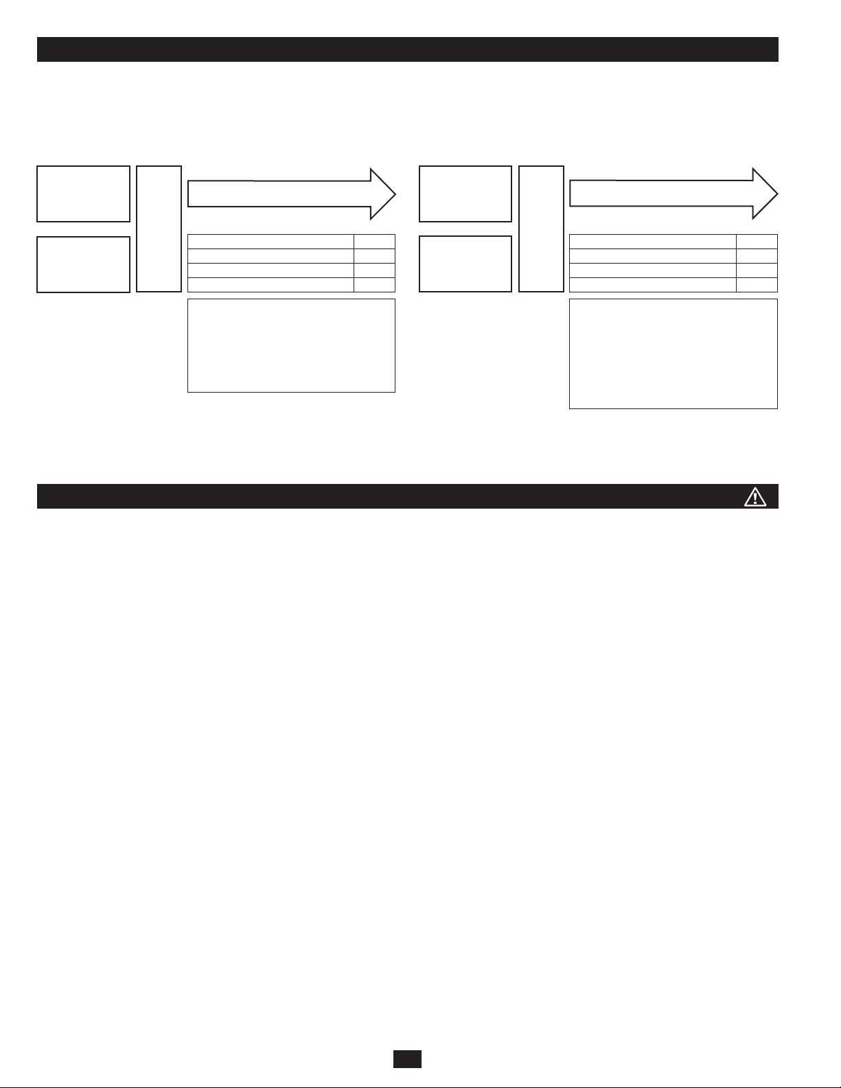
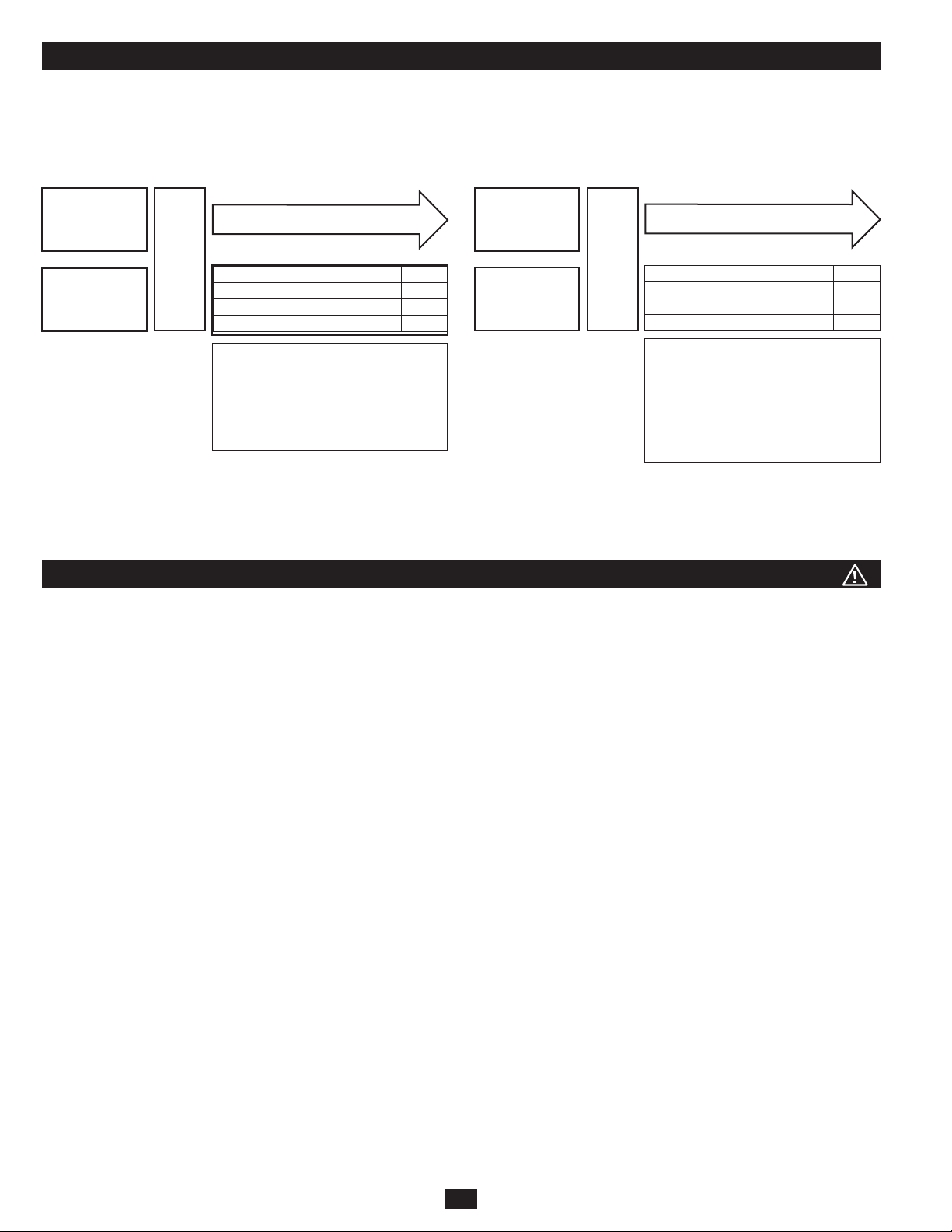
Congratulations! Your SUPDMB-Series Parallel PDU allows you to configure two 6kVA UPS systems for fault-tolerant operation or increased
output capacity. Your UPS will auto-configure for redundancy or increased capacity based on the attached equipment’s load. In order to configure
your UPS for redundancy, you will need to obtain two separate 6kVA UPS systems with parallel configuration ports and a SUPDMB12KHW
Parallel PDU module. Contact Tripp Lite for additional configuration help.
6kVA Redundant Configuration (6kVA max load) 12kVA Non-Redundant Configuration (12kVA max load)
6kVA UPS
6kVA UPS
Parallel
PDU
Loads 6kVA and lower
Redundant Operation YES
Fault-Tolerance YES
Hot-Swappable UPS Replacement YES
Increased Capacity NO
When two UPS systems are loaded to a
maximum of 50%, your conguration
will receive full redundancy—faulttolerance with full support for hotswappable UPS replacement in the case
of sudden UPS failure.
6kVA UPS
6kVA UPS
Parallel
PDU
Redundant Operation NO
Fault-Tolerance NO
Hot-Swappable UPS Replacement YES
Increased Capacity YES
When two UPS systems are loaded to a
maximum of 100%, your conguration
will receive the full capacity of both
UPS systems combined to power larger
loads. This conguration does NOT
carry redundancy or fault-tolerance.
Loads 6-12kVA
To ensure fault-tolerance, load the two parallel UPS systems to a
maximum of 50% of the combined rating for both UPS systems. For
example, if you have two 6kVA UPS systems, you will have fault-
You can use this conguration to grow your UPS power capacity to
12kVA In this conguration, fault-tolerance is NOT available.
tolerant operation if the load level remains at 6kVA or lower.
Important Safety Warnings
SAVE THESE INSTRUCTIONS. This manual contains important instructions and warnings that should be followed during the installation and
maintenance of this product.
Location Warnings
• Install the PDU Kit in a structurally sound area. Take care when moving and lifting the unit.
• Only operate your PDU Kit at indoor temperatures between 32° F and 104° F (between 0° C and 40° C). For best results, keep indoor
temperatures between 62° F and 84° F (between 17° C and 29° C).
Equipment Connection Warnings
• When connecting to the UPS systems, the UPS is connected to a DC energy source (battery). The output terminals may be live even when the
UPS is not connected to an AC supply.
• Use of this equipment in life support applications where failure of this equipment can reasonably be expected to cause the failure of the life
support equipment or to significantly affect its safety or effectiveness is not recommended. Do not use this equipment in the presence of a
flammable anesthetic mixture with air, oxygen or nitrous oxide.
Maintenance Warning
• Your PDU Kit does not require routine maintenance. Do not open the PDUs for any reason. There are no user-serviceable parts inside.
• Service and repair should be done only by trained personnel. Prior to any service work performed, all units should be turned off or manually
bypassed. Prior to any service work performed on power modules that plug directly into wall outlets, they should be turned off and unplugged.
Note that potentially lethal voltages exist as long as the battery supply is connected.
2
Page 3
Mounting
14
SW
14
SW
14
SW
14
SW
The user must determine the fitness of hardware and procedures before mounting. If hardware
and procedures are not suitable for your application, contact the manufacturer of your rack or
rack enclosure. The procedures described in this manual are for common rack and rack enclosure
types and may not be appropriate for all applications.
UPS System 1
Parallel configuration supports the mounting of two SU6000RT4UHVPM power/battery modules
for fault-tolerant redundancy that supports loads up to 6kVA, or, for increased capacity, up to
12kVA. For all 6kVA UPS system mounting instructions, please refer to that product’s Owner’s
Manual. In order to configure your UPS for redundancy, you will also need to obtain two
SU6000RT4UHVPM power/battery modules with this parallel kit.
1
It is important to note that in order to accommodate paralleling applications, the UPS systems
UPS System 2
1
must be mounted in the following order (see diagram 1): 6kVA UPS system 1 and 6kVA UPS
system 2. Note: Each 6kVA UPS system must be installed in separate rack rails before
attaching the rear parallel power distribution units.
2
Referring to the above step and the mounting instructions of the 6kVA UPS systems, mount
the two UPS systems into the 4-post rack. Once the UPS systems have been mounted in the
correct configuration (see Step 1), simply attach the primary PDU module to UPS system
1 and the secondary PDU module to UPS system 2 using the provided mounting screws as
shown.
2
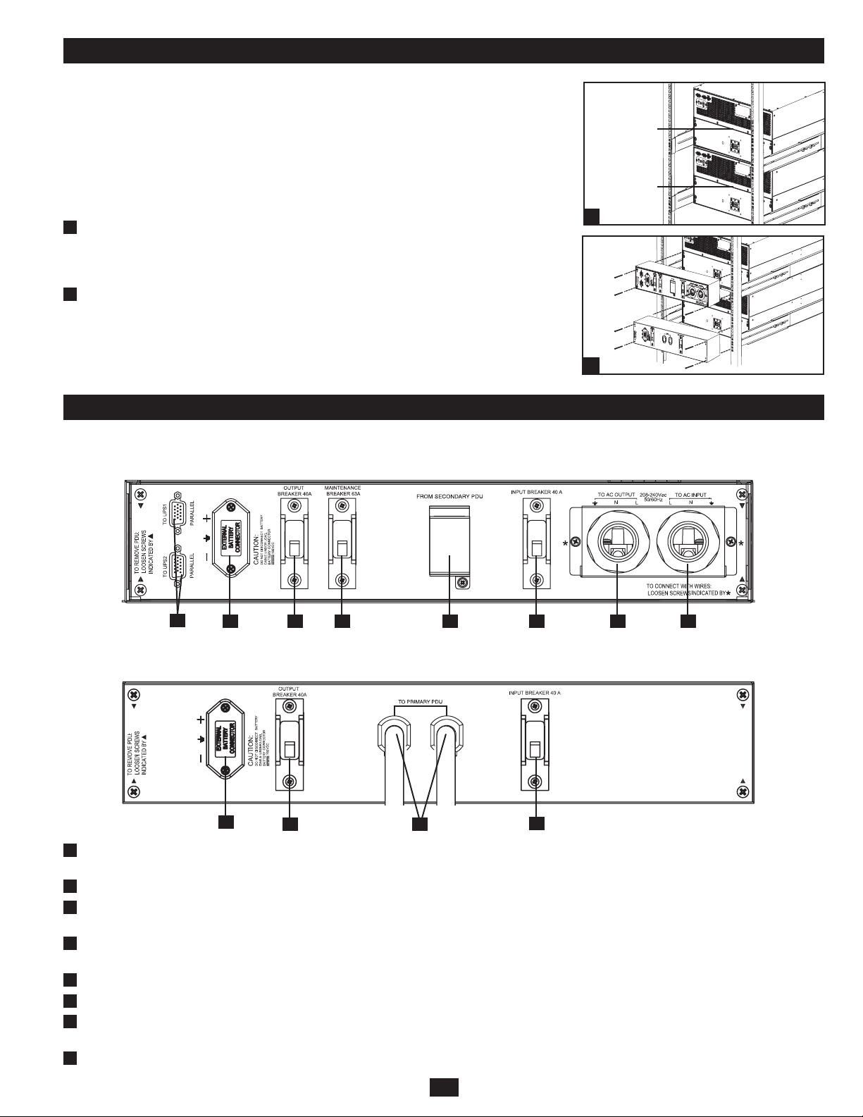
Features (Rear Panel)
Before installing and operating the PDU Kit, familiarize yourself with the location and function of the features of each component.
Primary Parallel PDU Module
2
1
8
7 6 5 4 3
Secondary Parallel PDU Module
1
1
External Battery Connector: Use this to connect one or more Tripp Lite battery modules to the power module. Remove the cover for access.
8
6
Refer to the battery module Owner’s Manual for connection instructions and safety warnings.
2
Parallel Connector: For UPS communication in parallel.
3
Utility Input Terminal Block: Use this terminal to connect your power module to utility power. Unscrew and remove the cover over the block
for access.
4
Equipment Output Terminal Block: Use this terminal to connect your power module to your equipment. Unscrew and remove the cover over
the block for access.
5
AC Input Breaker: One double-pole circuit breaker controls input power to the power module.
6
Parallel Power Interconnect: Connects Primary and Secondary Parallel PDUs.
7
Maintenance Breaker: Allows qualified service personnel to remove the detachable PDU from the power/battery module for routine
maintenance without disrupting power to the connected loads.
8
AC Output Breaker: One double-pole circuit breaker controls output power to the load.
3
5
Page 4
Connection
In order to make connections between 2 UPS systems in parallel, two 6kVA UPS systems, the primary detachable PDU module and the secondary
PDU module will be needed.
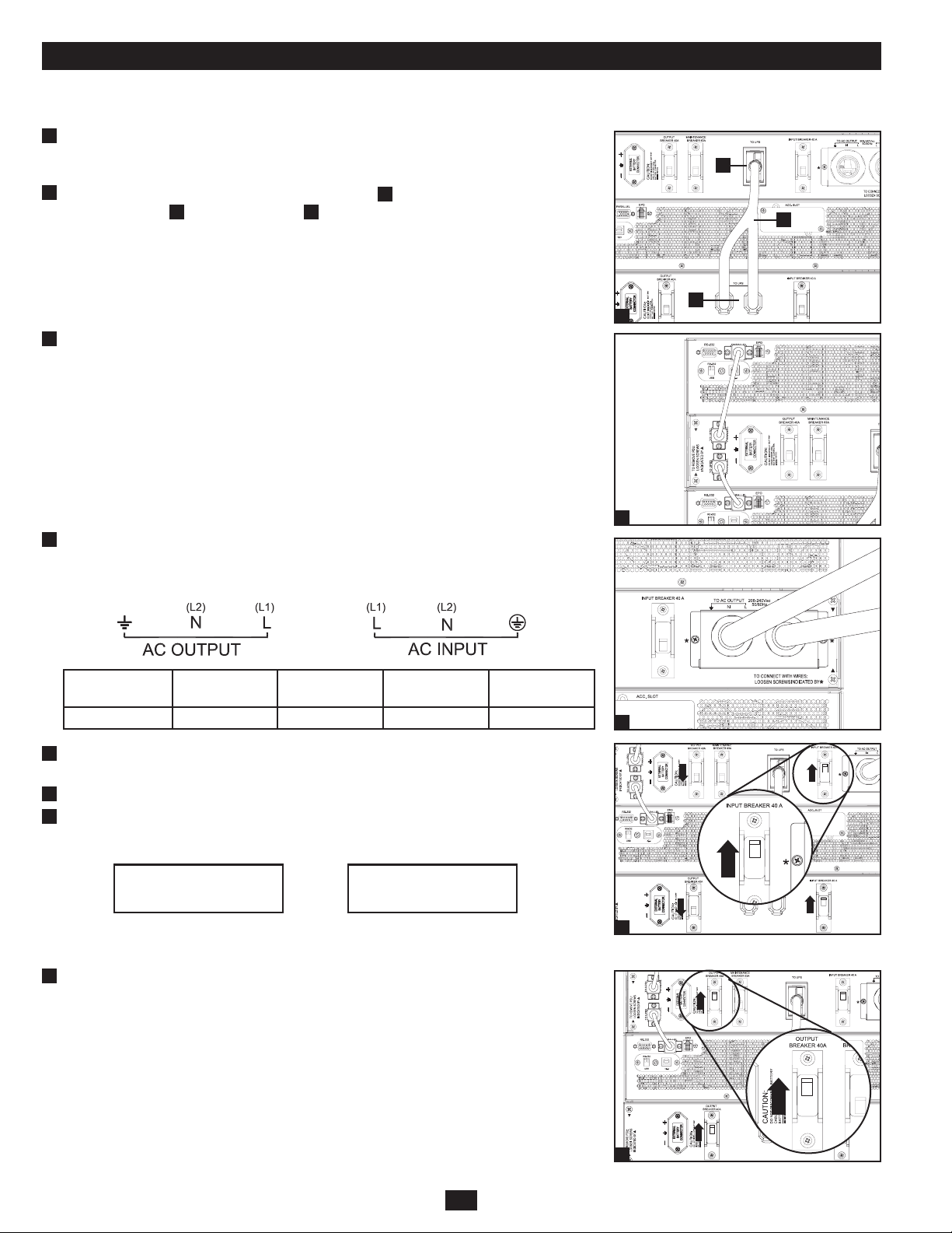
1
Being sure that all switches are off and all units are powered down, refer back to the
“Mounting” section of the manual. First, mount the UPS systems and then the primary and
secondary parallel PDUs.
2
Originating from the secondary PDU interconnect port
interconnect cable
3
Connect the 2 parallel cables. Both will originate from the primary parallel PDU with 1
B
to the primary PDU
C
as seen in diagram 2.
A
, connect the parallel power
connecting to UPS system 1 and the other to UPS system 2. (Refer to diagram 3.)
2
C
B
A
4
Connect the hardwired input and output AC power connections (L1, L2 and Ground wires) to
the primary PDU, according to the markings on the connectors. The AC input wiring attaches
to the facility’s AC source while the AC output wiring connects to the intended equipment.
Model Input Voltage
SUPDMB12KHW 200~240V (L-N) 60A 60A 8mm
5
With all switches in the OFF position, turn ON both the input breakers on the primary and
Maximum Rated
Input Current
Maximum Rated
Output Current
Typical
Wire Size
2
secondary PDUs. Leave switches for the output breakers in the OFF position.
6
Power ON UPS system 1, being sure that the output breakers are OFF.
7
After UPS system 1 start-up is complete, power ON UPS system 2. The UPS systems will self
detect the Parallel Mode and show the following screen shots for the primary and secondary
UPS systems:
PARALLEL: MASTER
V00 CV01
PARALLEL: SLAVE
V00 CV01
When the unit is in Parallel Mode UPS system 1 will display “Parallel: Master” and UPS
system 2 will display “Parallel: Slave”.
3
4
5
8
Once Parallel Mode is detected, turn on both output breakers for the primary and secondary
PDUs.
4
8
Page 5
Manual Bypass Operation (for UPS maintenance or replacement)
WARNING! For qualified service personnel only. Failure to follow the bypass procedure completely will not adequately power down
the UPS, resulting in the continued risk of death or injury from potential contact with high voltage. The UPS and detachable PDU are
extremely heavy. This procedure requires several people to perform.
The UPS system includes an independent, detachable PDU with a Maintenance Breaker Switch. This switch allows qualified service personnel
to remove the detachable PDU from the UPS for routine maintenance without disrupting power to connected loads. While this switch is set to
“BYPASS”, connected equipment will receive unfiltered AC mains power. But the equipment will not receive battery power in the event of a
blackout.
UPS Removal
STEP 1. Disable PowerAlert and disconnect the SNMP or serial USB communication cables from the communication ports on the UPS. Do NOT
remove the parallel cable (if installed) at this point.
STEP 2. First, determine your maintenance status (i.e. which UPS system requires maintenance and whether you are in Redundancy or Power
Mode). Press UPS’s “OFF” button, if the UPS is powered, until you hear a beep and see a “BYPASS MODE” message shown in its LCD
Display.
STEP 3. Part A: When the output is coming from the Primary UPS and the Secondary UPS needs repair, set the Primary PDU’s Input/Output
Breakers ON, the Secondary PDU’s Input/Output Breakers OFF and the Maintenance Breaker OFF.
Part B: When the output is coming from the Secondary UPS and the Primary UPS needs repair, set the Primary PDU’s Input/Output
Breakers OFF, the Secondary PDU’s Input/Output Breakers ON and the Maintenance Breaker OFF.
Part C: When the output is in Bypass, set Maintenance Breaker Switch to the ON position. At this point, remove the parallel cable from the
UPS.
STEP 4. If an external battery module is connected to the UPS, disconnect it from the UPS.
The UPS is now safely powered down and it can be detached from the PDU to perform maintenance/replacement.
STEP 5. Remove the four screws that secure the front mounting ears of your UPS to the rack. With the PDU still attached, move the UPS system
and PDU forward in the rack slightly (approximately 4 inches), being sure that both components remain adequately supported by the UPS’s
rackmount support rails.
STEP 6. At the rear of the UPS, remove the four screws that hold the detachable PDU to the UPS that is being serviced. With an assistant holding
the front of the UPS in place, carefully detach the PDU from the rear of the UPS and rest it on the UPS support rails. Remove the UPS from
the rack.
Output Status (Normal Operation)
Output coming from both UPS systems. ON ON OFF
Output Status (Redundancy Mode)
Output coming from Primary UPS.
Secondary UPS needs repair.
(Refer to Step 3, Part A)
Output coming from Secondary UPS.
Primary UPS needs repair.
(Refer to Step 3, Part B)
Output Status (Power Mode)
Output coming from Bypass.
(Refer to Step 3, Part C)
*On Primary PDU only.
Note: Units will operate in Redundancy Mode up to 6kVA and switch to Power Mode at loads greater than 6kVA.
Primary PDU Input/Output
Breakers
Primary PDU Input/Output
Breakers
ON OFF OFF
OFF ON OFF
Primary PDU Input/Output
Breakers
OFF OFF ON
Secondary PDU Input/Output
Breakers Maintenance Breaker*
Secondary PDU Input/Output
Breakers Maintenance Breaker*
Secondary PDU Input/Output
Breakers Maintenance Breaker*
5
Page 6

Storage and Service
Storage
The PDU Kit should be stored in a controlled indoor environment, away from moisture, temperature extremes, flammable liquids and gasses,
conductive contaminants, dust and direct sunlight. Store in its original shipping container if possible.
Service
Your Tripp Lite product is covered by the warranty described in this manual. A variety of Extended Warranty and On-Site Service Programs are
also available from Tripp Lite. For more information on service, visit www.tripplite.com/support. Before returning your product for service, follow
these steps:
1. Review the installation and operation procedures in this manual to insure that the service problem does not originate from a misreading of the
instructions.
2. If the problem continues, do not contact or return the product to the dealer. Instead, visit www.tripplite.com/support.
3. If the problem requires service, visit www.tripplite.com/support and click the Product Returns link. From here you can request a Returned
Material Authorization (RMA) number, which is required for service. This simple on-line form will ask for your unit’s model and serial
numbers, along with other general purchaser information. The RMA number, along with shipping instructions will be emailed to you. Any
damages (direct, indirect, special or consequential) to the product incurred during shipment to Tripp Lite or an authorized Tripp Lite service
center is not covered under warranty. Products shipped to Tripp Lite or an authorized Tripp Lite service center must have transportation charges
prepaid. Mark the RMA number on the outside of the package. If the product is within its warranty period, enclose a copy of your sales receipt.
Return the product for service using an insured carrier to the address given to you when you request the RMA.
Warranty & Warranty Registration
2-Year Limited
Seller warrants this product, if used in accordance with all applicable instructions, to be free from original defects in material and workmanship for a period of 2 years from the date of initial purchase. If
the product should prove defective in material or workmanship within that period, Seller will repair or replace the product, in its sole discretion. Service under this Warranty can only be obtained by your
delivering or shipping the product (with all shipping or delivery charges prepaid) to: Tripp Lite; 1111 W.35th Street; Chicago IL 60609; USA.Seller will pay return shipping charges. Visit www.tripplite.com/
support before sending any equipment back for repair.
THIS WARRANTY DOES NOT APPLY TO NORMAL WEAR OR TO DAMAGE RESULTING FROM ACCIDENT, MISUSE, ABUSE OR NEGLECT. SELLER MAKES NO EXPRESS WARRANTIES
OTHER THAN THE WARRANTY EXPRESSLY SET FORTH HEREIN. EXCEPT TO THE EXTENT PROHIBITED BY APPLICABLE LAW, ALL IMPLIED WARRANTIES, INCLUDING ALL WARRANTIES
OF MERCHANTABILITY OR FITNESS, ARE LIMITED IN DURATION TO THE WARRANTY PERIOD SET FORTH ABOVE; AND THIS WARRANTY EXPRESSLY EXCLUDES ALL INCIDENTAL AND
CONSEQUENTIAL DAMAGES. (Some states do not allow limitations on how long an implied warranty lasts, and some states do not allow the exclusion or limitation of incidental or consequential
damages, so the above limitations or exclusions may not apply to you. This Warranty gives you specific legal rights, and you may have other rights which vary from jurisdiction to jurisdiction).
Tripp Lite; 1111 W.35th Street; Chicago IL 60609; USA
WARNING: The individual user should take care to determine prior to use whether this device is suitable, adequate or safe for the use intended. Since individual applications are subject to great
variation, the manufacturer makes no representation or warranty as to the suitability or fitness of these devices for any specific application.
WARRANTY REGISTRATION
Visit www.tripplite.com/warranty today to register the warranty for your new Tripp Lite product. You’ll be automatically entered into a drawing for a chance to win a FREE Tripp Lite product!*
* No purchase necessary. Void where prohibited. Some restrictions apply. See website for details.
Regulatory Compliance Identification Numbers
For the purpose of regulatory compliance certifications and identification, your Tripp Lite product has been assigned a unique series number. The series number can be found on the product nameplate
label, along with all required approval markings and information. When requesting compliance information for this product, always refer to the series number. The series number should not be confused
with the marking name or model number of the product.
WEEE Compliance Information for Tripp Lite Customers and Recyclers (European Union)
Under the Waste Electrical and Electronic Equipment (WEEE) Directive and implementing regulations, when customers buy new electrical and electronic equipment from Tripp Lite they are entitled to:
• Send old equipment for recycling on a one-for-one, like-for-like basis (this varies depending on the country)
• Send the new equipment back for recycling when this ultimately becomes waste
Tripp Lite follows a policy of continuous improvement. Product specifications are subject to change without notice.
1111 W. 35th Street, Chicago, IL 60609 USA
www.tripplite.com/support
6
201005052 • 932903-EN
Page 7

Manual del propietario
Kit de PDU paralelo
para Sistemas UPS SmartOnline™ (6kVA)
Unidades de PDU paralelos principales y secundarios
Modelo: SUPDMB12KHW
Introducción 8
Advertencias de seguridad importantes 8
Montaje 9
Características 9
Conexión 10
Operación de derivación manual 11
Almacenamiento y servicio 12
Garantía 12
English 1
Français 13
Русский 19
1111 W. 35th Street, Chicago, IL 60609 USA
www.tripplite.com/support
Copyright © 2010 Tripp Lite. SmartOnline es una marca registrada de Tripp Lite. Todos los derechos reservados.
7
Page 8
Introducción
¡Felicitaciones! El PDU paralelo de la serie SUPDMB permite configurar dos sistemas UPS de 6kVA para la operación tolerante a las fallas o
la capacidad de salida en aumento. El UPS se configurará automáticamente para la redundancia o el aumento de la capacidad según la carga
de los equipos conectados. Para configurar el UPS para redundancia, deberá obtener dos sistemas UPS de 6 kVA por separado con puertos de
configuración paralelos y un módulo de PDU paralelo SUPDMB12KHW. Comuníquese con Tripp Lite si desea ayuda de configuración adicional.
Configuración redundante para 6kVA (6kVA de carga máx.) Configuración no redundante de 12kVA (12kVA de carga máx.)
UPS de 6kVA
UPS de 6kVA
PDU
paralelo
Cargas de 6kVA e inferiores
Operación redundante
Tolerancia a las fallas
Reemplazo del UPS en funcionamiento
Aumento de la capacidad
SÍ
SÍ
SÍ
NO
Cuando dos sistemas UPS se cargan a
un máximo de 50%, la conguración
recibirá redundancia total y tolerancia a
las fallas con soporte completo para el
reemplazo del UPS en funcionamiento en
el caso de una falla repentina del UPS.
UPS de 6kVA
UPS de 6kVA
PDU
paralelo
Operación redundante
Tolerancia a las fallas
Reemplazo del UPS en funcionamiento
Aumento de la capacidad
Cuando dos sistemas UPS se cargan a
un máximo de 100%, la conguración
recibirá la capacidad total de ambos
sistemas UPS combinados para
alimentar cargas más grandes. Esta
conguración NO conlleva redundancia
ni tolerancia a las fallas.
Cargas de 6kVA
NO
NO
SÍ
SÍ
Para garantizar la tolerancia a las fallas, cargue los dos sistemas
UPS paralelos a un máximo de 50% de los valores combinados para
ambos sistemas UPS. Por ejemplo, si posee dos sistemas UPS de
6kVA, contará con operación tolerante a las fallas si el nivel de carga
Puede utilizar esta conguración para aumentar la capacidad de
potencia del UPS a 12kVA En esta conguración, NO se dispone de
tolerancia a las fallas.
permanece en 6kVA o inferior.
Advertencias de seguridad importantes
GUARDE ESTAS INSTRUCCIONES Este manual contiene instrucciones y advertencias importantes que deben seguirse durante la instalación y
mantenimiento de este producto.
Advertencias de ubicación
• Instale el kit de PDU en una zona estructuralmente sana. Tenga cuidado al mover y elevar la unidad.
• Opere el kit de PDU únicamente en temperatura ambiente interior entre 32° y 104 °F (0 °C y 40° C). Para obtener los mejores resultados,
mantenga la temperatura interior entre 62 °F y 84 °F (17 °C y 29 °C).
Advertencias sobre la conexión de equipos
• Cuando lo conecta a un sistema UPS, el UPS está conectado a una fuente de energía de CD (batería). Los terminales de salida pueden tener
corriente aún cuando el sistema de UPS no esté conectado a una fuente de CA.
• No se recomienda usar este equipo en aplicaciones de mantenimiento artificial de la vida, donde se puede esperar razonablemente que su
falla cause la falla del equipo de mantenimiento de la vida o que afecte de manera importante su seguridad o eficiencia. No use este equipo en
presencia de mezclas anestésicas inflamables con aire, oxígeno u óxido nitroso.
Advertencias de mantenimiento
• Su kit de PDU no requiere rutina de mantenimiento. Bajo ninguna circunstancia abra el PDU. No tiene partes internas que el usuario pueda reparar.
• Sólo personal capacitado debe llevar a cabo el mantenimiento y la reparación. Antes de llevar a cabo el trabajo de servicio, deben apagarse
todas las unidades por derivación manual. Antes de realizar el mantenimiento en módulos de alimentación que se conecten directamente
a tomacorrientes de pared, deben apagarse y desenchufarse. Tenga en cuenta que existen voltajes potencialmente mortales siempre que el
suministro de la batería esté conectado.
8
Page 9

Montaje
14
SW
14
SW
14
SW
14
SW
El usuario debe determinar la aptitud de las herramientas y los pasos antes de montarlo. Si las
herramientas o los procedimientos no son adecuados para la aplicación, comuníquese con el
fabricante del rack o del gabinete del rack. Las instrucciones de este manual son para racks
comunes y racks de bastidor y pueden no ser adecuadas para todas las aplicaciones.
Sistema UPS 1
La configuración en paralelo admite el montaje de dos módulos de alimentación/batería
SU6000RT4UHVPM para redundancia tolerante a las fallas que soporta cargas hasta de 6kVA
o, para un aumento de capacidad, de hasta 12kVA. Para todas las instrucciones de montaje del
sistema UPS de 6kVA, consulte el Manual del propietario de ese producto. Para poder configurar
el UPS para redundancia, también deberá obtener dos módulos de alimentación/batería
SU6000RT4UHVPM con este kit paralelo.
1
Es importante tener en cuenta que, para acomodar aplicaciones paralelas, los sistemas UPS
Sistema UPS 2
1
tienen que montarse en el siguiente orden (consulte el diagrama): Sistema UPS 1 6kVA y
sistema UPS 2 6kVA. Nota: Cada sistema UPS 6kVA debe instalarse en rieles de rack
separados antes de unir las unidades de distribución de alimentación paralela traseras.
2
Consultando el paso anterior y las instrucciones de montaje de los sistemas UPS de 6kVA,
monte los dos sistemas UPS en el rack de 4 puestos. Una vez que se han montado los sistemas
UPS en la configuración correcta (consulte el Paso 1), sólo una el módulo PDU principal
al sistema UPS 1 y el módulo PDU secundario al sistema UPS 2 utilizando los tornillos de
montaje suministrados como se muestra en la figura.
2
Características (Panel trasero)
Antes de instalar y hacer funcionar el kit de PDU, debe familiarizarse con la ubicación y función de las características de cada componente.
Módulo de PDU paralelo principal
2
1
8
7 6 5 4 3
Módulo de PDU paralelo secundario
1
1
Conector de batería externo: Utilícelo para conectar uno o más módulos de baterías de Tripp Lite al módulo de alimentación. Extraiga la
8
6
cubierta para obtener acceso. Consulte el Manual del propietario del módulo de la batería para obtener las instrucciones de conexión y las
advertencias de seguridad.
2
Conector paralelo: Para la comunicación en paralelo del UPS.
3
Bloque de terminales de entrada de la red pública: Utilice este terminal para conectar el módulo de alimentación a la red pública. Para
acceder al bloque, desatornille y retire la tapa por encima.
4
Bloque del terminal de salida del equipo: Utilice este terminal para conectar el módulo de alimentación a los equipos. Para acceder al bloque,
desatornille y retire la tapa por encima.
5
6
7
8
Disyuntor de entrada de CA: Un disyuntor de dos polos controla la alimentación de entrada al módulo de alimentación.
Interconexión de alimentación paralela: Conecte los PDU principal y secundarios.
Disyuntor de mantenimiento: Permite al personal de servicio calificado retirar la PDU desmontable del módulo de potencia/batería para
realizar el mantenimiento de rutina sin interrumpir la energía a las cargas conectadas.
Disyuntor de salida de CA: Un disyuntor de dos polos controla la alimentación de salida a la carga.
9
5
Page 10

Connection
Para poder realizar conexiones entre 2 sistemas UPS en paralelo, se necesitarán dos sistemas UPS de 6kVA, el módulo PDU desmontable principal
y el módulo PDU secundario.
1
Asegurándose de que todos los interruptores estén apagados y de que la unidad esté apagada,
consulte la sección “Montaje” de este manual. En primer lugar, monte los sistemas UPS y
luego los PDU paralelos principal y secundario.
2
Empezando desde el puerto de interconexión
de interconexión de alimentación paralelo
A
del PDU secundario, conecte el cable
B
al PDU principal
C
como se muestra en el
diagrama 2.
3
Conecte los 2 cables paralelos. Ambos a partir del PDU paralelo principal con uno
conectándose al sistema UPS 1 y el otro al sistema UPS 2. (Consulte el diagrama 3.)
2
C
B
A
4
Conecte las conexiones de alimentación de CA de entrada y salida de alimentación
permanente (L1, L2 y cables de conexión a tierra) al PDU principal, según las marcas en los
conectores. El cableado de entrada de CA se conecta a la fuente de CA de la instalación en
tanto que el cableado de salida de CA se conecta a los equipos deseados.
Modelo
SUPDMB12KHW 200~240V (L-N) 60A 60A 8mm
5
Con todos los interruptores en la posición de apagado, ENCIENDA ambos disyuntores de
Voltaje de
entrada
Corriente de entrada
nominal máxima
Corriente de salida
nominal máxima
Tamaño típico
del cable
2
entrada en los PDU principal y secundarios. Deje los interruptores de los disyuntores de
salida en la posición de APAGADO.
6
ENCIENDA el sistema UPS 1, asegurándose de que los disyuntores de salida estén APAGADOS.
7
Luego de arrancar por completo el sistema UPS 1, ENCIENDA el sistema UPS 2. Los
sistemas UPS detectarán automáticamente el modo paralelo y mostrarán las siguientes
pantallas para los sistemas UPS principal y secundario:
PARALLEL: MASTER
V00 CV01
PARALLEL: SLAVE
V00 CV01
Cuando la unidad esté en Modo paralelo, el sistema UPS 1 mostrará “Paralelo: Maestro” y el
sistema UPS 2 mostrará “Paralelo: Esclavo”.
3
4
5
8
Una vez que se detecte el Modo paralelo, encienda los dos disyuntores para los PDU principal
y secundario.
10
8
Page 11

Operación de derivación manual (para el mantenimiento o reemplazo del UPS)
¡ADVERTENCIA! Únicamente para personal de servicio calificado. No seguir el procedimiento de rodeo con exactitud causará que el UPS
no se apague adecuadamente, lo que resultará en el riesgo continuo de muerte o lesiones a causa del contacto potencial con alto voltaje. El
UPS y la PDU desmontables son extremadamente pesados. Este procedimiento requiere la participación de varias personas.
El sistema UPS incluye una PDU desmontable e independiente con un Interruptor disyuntor de mantenimiento. Este interruptor permite al
personal de servicio calificado retirar la PDU desmontable del UPS para realizar el mantenimiento de rutina sin interrumpir la energía a las cargas
conectadas. Mientras este interruptor esté establecido en “DERIVACIÓN”, los equipos conectados recibirán alimentación de la red eléctrica de CA
sin filtro. Pero los equipos no recibirán alimentación de la batería en el caso de un apagón.
Extracción del UPS
PASO 1. Deshabilite PowerAlert y desconecte los cables de comunicación SNMP o USB serial de los puertos de comunicación en el UPS. Todavía
NO desconecte el cable paralelo (si está instalado).
PASO 2. En primer lugar, determine el estado del mantenimiento (es decir, qué sistema UPS requiere mantenimiento y si se encuentra en modo de
Redundancia o de Alimentación). Si el UPS recibe energía, presione el botón “OFF” del UPS hasta que escuche un pitido y el mensaje
“BYPASS MODE” (modo de derivación) aparezca en la pantalla LCD.
PASO 3. Parte A: Cuando la salida se obtenga del UPS principal y el UPS secundario necesite reparación, ENCIENDA los disyuntores de entrada/
salida del PDU principal, APAGUE los disyuntores de salida del PDU secundario y el disyuntor de mantenimiento.
Parte B: Cuando la salida se obtenga del UPS secundario y el UPS principal necesite reparación, APAGUE los disyuntores de entrada/sali-
da del PDU principal, ENCIENDA los disyuntores de salida del PDU secundario y APAGUE el disyuntor de mantenimiento.
Parte C: Cuando la salida esté en modo de derivación, coloque el interruptor disyuntor de mantenimiento en la posición de ENCENDIDO.
En este momento, desconecte el cable paralelo del UPS.
PASO 4. Si hay un módulo de baterías externas conectado al UPS, desconéctelo.
El UPS ahora está apagado de manera segura y puede desconectarse del PDU para realizar el mantenimiento/reemplazo.
PASO 5. Quite los cuatro tornillos que aseguran las orejas de montaje frontales del UPS al rack. Con la PDU aún unida, mueva el sistema UPS y la
PDU hacia adelante en el rack levemente (aproximadamente 4 pulgadas), asegurándose de que ambos componentes permanezcan adecuadamente soportados por los rieles de montaje de soporte del UPS.
PASO 6. En la parte trasera del UPS, extraiga los cuatro tornillos que sostienen la PDU desmontable al UPS al que se le está realizando el servicio.
Con un asistente que sostenga la parte frontal del UPS en su lugar, desmonte cuidadosamente la PDU de la parte trasera del UPS y apóyelo
en los rieles de soporte del UPS. Extraiga el UPS del rack.
Estado de la salida (operación normal)
Salida obtenida de ambos sistemas UPS. ENCENDIDO ENCENDIDO APAGADO
Estado de la salida (modo
redundancia)
Salida obtenida del sistema UPS
principal. UPS secundario necesita
reparación. (Consulte el Paso 3, Parte A)
Salida obtenida del UPS secundario.
UPS principal necesita reparación.
(Consulte el Paso 3, Parte B)
Estado de la salida (modo
alimentación)
Salida obtenida de derivación.
(Consulte el Paso 3, Parte C)
*Únicamente la PDU principal.
Nota: L as unidades operarán en modo redundante hasta 6kVA y con cargas superiores a los 6kVA conmutarán a modo de alimentación.
Disyuntores de entrada/salida
del PDU principales
Disyuntores de entrada/salida
del PDU principal
ENCENDIDO APAGADO APAGADO
APAGADO ENCENDIDO APAGADO
Disyuntores de entrada/salida
del PDU principal
APAGADO APAGADO ENCENDIDO
Disyuntores de entrada/salida
del PDU secundario Disyuntor de mantenimiento*
Disyuntores de entrada/salida
del PDU secundario Disyuntor de mantenimiento*
Disyuntores de entrada/salida
del PDU secundario Disyuntor de mantenimiento*
11
Page 12

Almacenamiento y servicio
Almacenamiento
El kit del PDU debe almacenarse en un ambiente interior controlado, lejos de la humedad, temperaturas extremas, líquidos y gases inflamables,
contaminantes conductores, polvo y luz solar directa. Si es posible, almacénelo en su contenedor de envío original.
Servicio
Su producto Tripp Lite está cubierto por la garantía descrita en este manual. Tripp Lite también pone a disposición una variedad de garantías
extendidas y programas de servicio en el sitio. Para obtener más información sobre mantenimiento, visite www.tripplite.com/support. Antes de
enviar el producto a mantenimiento, siga estos pasos:
1. Revise los procedimientos de instalación y operación descritos en este manual para asegurarse de que el problema de servicio no se origina en
una mala comprensión de las instrucciones.
2. Si el problema continúa, no se comunique ni devuelva el producto al distribuidor. En su lugar, visite www.tripplite.com/support.
3. Si el problema requiere servicio, visite www.tripplite.com/support y haga clic en el enlace Devolución de productos. Aquí puede solicitar un
número de autorización de devolución de mercadería (RMA), que es necesario para el servicio. En este simple formulario en línea se le pedirá
el modelo y números de serie de su unidad, junto con otra información general sobre el comprador. El número RMA y las instrucciones para el
envío se le enviarán por correo electrónico. Esta garantía no cubre ningún daño (directo, indirecto, especial o consecuencial) que el producto
sufra durante el envío a Tripp Lite o un centro de servicio autorizado por Tripp Lite. Los productos que se envían a Tripp Lite o un centro de
servicio autorizado por Tripp Lite deben tener prepagos los cargos de envío. Escriba el número RMA en el exterior del paquete. Si el producto
se encuentra dentro del período de garantía, adjunte una copia del recibo de venta. Envíe el producto para servicio a través de un transportador
asegurado a la dirección que se le proporcione cuando solicite el RMA.
Garantía
Garantía limitada por 2 años
El vendedor garantiza que este producto no tiene defectos originales de materiales ni de mano de obra por un período de cinco años a partir de la fecha original de compra, si se utiliza de acuerdo con
todas las instrucciones correspondientes. En caso de demostrarse dentro de ese período que el producto tiene defectos de materiales o de mano de obra, el vendedor lo reparará o reemplazará a su
exclusiva discreción. El servicio técnico bajo esta garantía solo puede ser obtenido si usted entrega o envía el producto (con todos los cargos de envío o entrega prepagos) a: Tripp Lite, 1111 W.35th
Street, Chicago, IL 60609; EE. UU. El vendedor abonará los cargos de envío de devolución. Visite www.tripplite.com/support antes de enviar cualquier equipo para reparación.
ESTA GARANTÍA NO CUBRE EL DESGASTE NORMAL NI LOS DAÑOS CAUSADOS POR ACCIDENTES, MAL USO, ABUSO O NEGLIGENCIA. EL VENDEDOR NO OFRECE NINGUNA GARANTÍA
EXPRESA QUE NO SEA LA ESTABLECIDA EXPRESAMENTE EN EL PRESENTE DOCUMENTO. EXCEPTO EN LA MEDIDA EN QUE LO PROHÍBAN LAS LEYES APLICABLES, LA DURACIÓN DE
TODAS LAS GARANTÍAS IMPLÍCITAS, INCLUIDAS LAS DE COMERCIABILIDAD O APTITUD, SE LIMITA AL PERÍODO DE GARANTÍA ANTES MENCIONADO Y ESTA GARANTÍA EXCLUYE
EXPRESAMENTE TODOS LOS DAÑOS INCIDENTALES E INDIRECTOS. (Algunos Estados no permiten las limitaciones a la duración de una garantía implícita y algunos Estados no permiten la
exclusión o limitación de los daños incidentales o indirectos, de modo que las limitaciones o exclusiones antes mencionadas pueden no corresponder en su caso. Esta garantía le otorga derechos
legales específicos y usted puede tener otros derechos que varían de una jurisdicción a otra).
Tripp Lite; 1111 W.35th Street; Chicago IL 60609; EE. UU.
ADVERTENCIA: Antes de usar este dispositivo, cada usuario debe ocuparse de determinar si es apto, adecuado o seguro para el uso que pretende darle. Dado que las aplicaciones individuales están
sujetas a diversas variaciones, el fabricante no representa ni garantiza la idoneidad o condición de estos dispositivos para cualquier aplicación específica.
Conformidad con las regulaciones sobre números de identificación
Con el objeto de cumplir con las regulaciones de certificaciones e identificación, a su producto Tripp Lite se le ha asignado un número de serie único. Puede encontrar el número de serie en la etiqueta
o placa de identificación del producto, junto con todas las marcas de aprobación e información necesarias. Cuando solicite información de cumplimiento de este producto, siempre haga referencia al
número de serie. El número de serie no debe confundirse con el nombre de marca o el número de modelo del producto.
Información sobre el cumplimiento de la WEEE para clientes de Tripp Lite y técnicos de reciclaje (Unión Europea)
Bajo la Directiva de Residuos de Aparatos Eléctricos y Electrónicos (WEEE) y las reglamentaciones reguladoras, cuando los clientes compran cualquier equipo eléctrico y electrónico nuevo de Tripp Lite
tienen derecho a:
• Regresar el equipo viejo para reciclaje por uno igual o por uno semejante (esto varía de acuerdo con el país)
• Regresar el equipo nuevo para que sea reciclado cuando finalmente se convierte en un desecho Tripp Lite tiene la política de mejora continua.
Las especificaciones del producto están sujetas a cambios sin notificación previa.
1111 W. 35th Street, Chicago, IL 60609 USA
www.tripplite.com/support
12
201005052 • 932903-SP
Page 13

Manuel de l’utilisateur
Ensemble de PDU parallèle
pour systèmes d’ASI SmartOnline™ (6kVA)
Unités PDU parallèles principales et secondaires
Modèle : SUPDMB12KHW
Introduction 14
Consignes de sécurité importantes 14
Montage 15
Caractéristiques 15
Raccordement 16
Opération de dérivation manuelle 17
Entreposage et service 18
Garantie 18
English 1
Español 7
Русский 19
1111 W. 35th Street, Chicago, IL 60609 USA
www.tripplite.com/support
Copyright © 2010 Tripp Lite. SmartOnline est une marque de commerce de Tripp Lite. Tous droits réservés.
13
Page 14

Introduction
Félicitations! Votre PDU parallèle de la série SUPDMB vous permet de configurer deux systèmes d’ASI de 6kVA pour une capacité de rendement
accrue ou un fonctionnement tolérant aux pannes. Votre ASI configurera de manière automatisée sa redondance ou sa capacité accrue à partir
de la charge de l’équipement connecté. Afin de configurer la redondance de votre ASI, vous devrez disposer de deux systèmes d’ASI de 6 kVA
indépendents avec des ports de configuration parallèle et d’un module de PDU parallèle SUPDMB12KHW. Contactez Tripp Lite pour une aide
supplémentaire concernant la configuration.
Configuration redondante de 6kVA (charge maximale de 6kVA) Configuration redondante de 12kVA (charge maximale de 12kVA)
ASI de 6kVA
ASI de 6kVA
PDU
parallèle
Charges de 6kVA et moins
Fonctionnement redondant OUI
Tolérance aux pannes OUI
Remplacement à chaud de l’ASI OUI
Capacité accrue NON
Lorsque deux systèmes d’ASI sont
chargés à un maximum de 50 %, votre
conguration reçoit une redondance
totale—tolérance aux pannes avec prise
en charge totale d’un remplacement à
chaud de l’ASI en cas de défaillance
soudaine de l’ASI.
ASI de 6kVA
PDU
parallèle
ASI de 6kVA
Charges de 6 à 12kVA
Fonctionnement redondant NON
Tolérance aux pannes NON
Remplacement à chaud de l’ASI OUI
Capacité accrue OUI
Lorsque deux systèmes d’ASI sont
chargés à un maximum de 100 %, votre
conguration reçoit la pleine capacité
des deux systèmes d’ASI combinés pour
alimenter des charges plus importantes.
Cette conguration n’offre PAS de
redondance ou de tolérance aux pannes.
Pour garantir une tolérance aux pannes, chargez les deux systèmes
d’ASI parallèles à un maximum de 50 % des indices combinés pour
les deux systèmes d’ASI. Par exemple, si vous possédez deux systèmes
d’ASI de 6kVA, vous bénécierez d’un fonctionnement tolérant aux
Vous pouvez utiliser cette conguration pour augmenter la capacité
électrique de votre ASI à 12kVA. Dans cette conguration, il n’y a PAS
de tolérance aux pannes.
pannes si le niveau de charge reste à 6kVA ou moins.
Consignes de sécurité importantes
CONSERVEZ CES INSTRUCTIONS. Ce manuel contient des consignes et des instructions importantes devant être suivies pendant l’installation et
l’entretien de ce produit.
Avertissements concernant l’emplacement de la PDU
• Installez l’ensemble de la PDU dans une zone structurellement sûre. Déplacez et soulevez l’unité avec précaution.
• Utilisez votre PDU uniquement à une température ambiante se situant entre 0° C et 40° C (entre 32° F et 104° F). Pour de meilleurs résultats,
maintenez la température ambiante entre 17° C et 29° C (62° F et 84° F).
Avertissements concernant le branchement de l’équipement
• Lorsque vous connectez la PDU aux systèmes d’ASI, l’ASI est connectée à une source d’énergie de CC (batterie). Les terminaux de sortie
peuvent être alimentés même lorsque l’ASI n’est pas connectée à une alimentation de CA.
• Il est déconseillé d’utiliser cet équipement dans des applications médicales où une panne de cet équipement pourrait normalement provoquer
la panne de l’équipement de survie ou altérer notablement sa sécurité ou son efficacité. N’utilisez pas cet équipement en présence de mélanges
anesthésiques inflammables avec de l’air, de l’oxygène ou de l’oxyde nitreux.
Avertissements concernant l’entretien
• Votre PDU ne nécessite aucune opération d’entretien. Ne l’ouvrir sous aucun prétexte. Aucune pièce ne peut être réparée par l’utilisateur.
• Les travaux d’entretien et de réparation doivent être effectués uniquement par un technicien formé. Tous travaux de réparation sur la PDU
doivent être réalisés après une mise hors tension ou une dérivation manuelle de celle-ci. Tous travaux de réparation sur des modules électriques
se branchant directement sur des prises murales doivent être réalisés après une mise hors tension et un débranchement de ceux-ci. Veuillez noter
qu’il est possible que la tension de cette unité atteigne un niveau excessif (voire mortel) tant que la batterie est raccordée au courant.
14
Page 15

Montage
14
SW
14
SW
14
SW
14
SW
Il incombe à l’utilisateur de déterminer la compatibilité du matériel et des procédures avant de
commencer le montage. Si le matériel ou les procédures ne correspondent pas à votre application,
veuillez contacter le fabricant de votre bâti ou de la baie. Les procédures décrites dans le présent
manuel sont prévues pour les types de bâtis et baies couramment utilisés et il se peut qu’elles ne
Système d’ASI 1
conviennent pas à toutes les applications.
La configuration parallèle supporte le montage de deux modules électriques/à batteries
SU6000RT4UHVPM pour une redondance tolérante aux pannes qui soutient des charges
allant jusqu’à 6kVA, ou, pour une capacité accrue, jusqu’à 12kVA. Pour toutes les instructions
de montage du système d’ASI de 6kVA, veuillez vous reporter au manuel de l’utilisateur de ce
produit. Afin de configurer la redondance de votre ASI, vous devrez vous procurer deux modules
Système d’ASI 2
1
électriques/à batteries SU6000RT4UHVPM en plus de ce ensemble parallèle.
1
Il est important de noter qu’afin d’accommoder les applications de mise en parallèle, les
systèmes d’ASI doivent être montés dans l’ordre suivant (voir schéma 1) : Système d’ASI de
6kVA n° 1 et système d’ASI de 6kVA n° 2. Remarque : Chaque système d’ASI de 6kVA
doit être installé dans un des rails de bâti séparé avant de fixer les unités de distribution
d’alimentation parallèles arrière.
2
En vous reportant à l’étape ci-dessus et aux instructions de montage des systèmes d’ASI de
6kVA, montez les deux systèmes d’ASI dans le bâti à 4 montants. Une fois que les systèmes
d’ASI ont été correctement montés (voir l’étape 1), fixez simplement le module de la PDU
2
principal au système d’ASI n° 1 et le module de la PDU secondaire au système d’ASI n° 2 en
utilisant les vis de montage fournies tel qu’illustré.
Caractéristiques (panneau arrière)
Avant d’installer et de mettre le PDU en marche, familiarisez-vous avec la position et l’utilité des caractéristiques de chaque composant.
Module de la PDU parallèle principal
2
1
8
7 6 5 4 3
Module de la PDU parallèle secondaire
1
1
Connecteur de batterie externe : Utilisez ce connecteur pour raccorder un ou plusieurs module(s) de batterie Tripp Lite au module
8
6
d’alimentation. Retirez le couvercle pour faciliter l’accès. Consultez le manuel de l’utilisateur relatif au module de batterie pour obtenir les
consignes de raccordement et les avertissements en matière de sécurité.
2
Connecteur parallèle : Pour une communication ASI en parallèle.
3
Bloc de branchement d’entrée de l’électricité utilitaire : Utilisez cette borne pour raccorder votre module d’alimentation à votre équipement.
Dévissez et retirez le couvercle de la plaque pour faciliter l’accès.
4
Plaque à borne de sortie de l’équipement : Utilisez ce terminal pour raccorder votre module d’alimentation à votre équipement. Dévissez et
retirez la protection du bloc pour faciliter l’accès.
5
6
7
8
Disjoncteur d’entrée CA : Un coupe-circuit bipolaire contrôle l’alimentation d’entrée du module d’alimentation.
Interconnecteur électrique parallèle : Connecte les UDA parallèles principale et secondaire.
Disjoncteur de maintenance : Permet au technicien qualifié de retirer la PDU du module d’alimentation/à batterie pour effectuer les travaux de
maintenance réguliers sans interrompre l’alimentation vers les charges raccordées.
Disjoncteur de sortie CA : Un coupe-circuit bipolaire contrôle l’alimentation de sortie de la charge.
15
5
Page 16

Raccordement
Pour effectuer des raccordements entre 2 systèmes d’ASI en parallèle, 2 systèmes d’ASI de 6kVA, le module du PDU principal amovible et le module
de la PDU secondaire seront nécessaires.
1
En vous assurant que tous les interrupteurs sont éteints et que toutes les unités sont coupées,
reportez-vous à la section « Montage » du manuel. Montez d’abord les systèmes d’ASI puis les
PDU parallèles principale et secondaire.
2
À partir du port d’interconnexion
interconnecteur de courant
3
Connectez les 2 câbles parallèles. Les deux partiront de la PDU parallèle principale, l’un se
A
de la PDU secondaire, connectez le câble
B
parallèle à la PDU principal
C
(voir schéma 2).
connectant au système d’ASI n° 1 et l’autre au système d’ASI n° 2 (voir schéma 3).
2
C
B
A
4
Connectez l’entrée câblée et les raccordements électriques de CA de sortie (L1, L2 et câbles
de terre) à la PDU principale, selon les marquages des connecteurs. Le câblage d’entrée CA
se fixe à la source de CA de l’installation tandis que le câblage de sortie CA se connecte à
l’équipement voulu.
Modèle Tension d’entrée
SUPDMB12KHW 200~240V (L-N) 60A 60A 8mm
5
Avec tous les interrupteurs en position OFF, allumez les deux disjoncteurs d’entrée sur les PDU
Courant nominal
d’entrée maximal
Courant nominal
de sortie maximal
Taille type des
câbles
2
principale et secondaire. Laissez les interrupteurs des disjoncteurs de sortie en position OFF.
6
Allumez le système d’ASI n° 1, en vous assurant que tous les disjoncteurs de sortie sont éteints.
7
Une fois que le démarrage du système d’ASI n° 1 terminé, allumez le système d’ASI n° 2. Les
systèmes d’ASI détecteront automatiquement le mode parallèle et afficheront les captures
d’écran suivantes pour les systèmes d’ASI principal et secondaire :
PARALLEL: MASTER
V00 CV01
PARALLEL: SLAVE
V00 CV01
Lorsque l’unité est en mode parallèle, le système d’ASI n° 1 affichera « Parallel: Master »
(Parallèle : maître) et le système d’ASI n° 2 affichera « Parallel: Slave » (parallèle esclave).
3
4
5
8
Une fois le mode parallèle détecté, allumez les deux disjoncteurs de sortie pour les PDU
principale et secondaire.
16
8
Page 17

Opération de dérivation manuelle (pour le remplacement ou l’entretien de l’ASI)
ATTENTION! Réservé aux techniciens qualifiés uniquement. Si vous ne respectez pas la procédure de dérivation à la lettre, l’ASI ne
s’éteindra pas correctement, ce qui peut présenter un danger de mort ou de préjudice grave en cas de contact avec une haute tension. L’ASI
et la PDU amovible sont extrêmement lourdes. L’exécution de cette procédure requiert plusieurs personnes.
Le système d’ASI comprend une PDU indépendante et amovible dotée d’un commutateur de disjoncteur de maintenance. Ce commutateur permet
au technicien qualifié de retirer la PDU amovible de l’ASI pour effectuer les travaux de maintenance réguliers sans interrompre l’alimentation vers
les charges raccordées. Lorsque ce commutateur est positionné sur « BYPASS » (dérivation), l’équipement raccordé recevra le courant de service
CA non filtré, mais il ne recevra pas l’alimentation de la batterie en cas de panne.
Retrait de l’ASI
ÉTAPE 1. Désactivez le logiciel PowerAlert et retirez les câbles de communication SNMP ou de série USB des ports de communication de l’ASI.
Ne retirez PAS le câble parallèle (si installé) tout de suite.
ÉTAPE 2. Déterminez d’abord votre statut de maintenance (à savoir, quel système d’ASI requiert une maintenance, et si vous vous trouvez en mode
Redondance ou Alimentation). Pressez le bouton OFF de l’ASI, si elle est allumée, jusqu’à ce que vous entendiez un bip et voyiez le message « BYPASS MODE » (Mode dérivation) s’afcher sur son écran LCD.
ÉTAPE 3. Partie A : Lorsque la sortie provient de l’ASI principale et que l’ASI secondaire a besoin de réparations, réglez les disjoncteurs d’entrée/de
sortie de la PDU principale sur ON, les disjoncteurs d’entrée/de sortie de la PDU secondaire sur OFF, et le disjoncteur de maintenance sur OFF.
Partie B : Lorsque la sortie provient de l’ASI secondaire et que l’ASI principale a besoin de réparations, réglez les disjoncteurs d’entrée/de
sortie de la PDU principale sur OFF, les disjoncteurs d’entrée/de sortie de la PDU secondaire sur ON, et le disjoncteur de maintenance sur OFF.
Partie C : Lorsque la sortie est en dérivation, réglez le commutateur de disjoncteur de maintenance en position ON. Retirez maintenant le
câble parallèle de l’ASI.
ÉTAPE 4. Si un module de batterie externe est raccordé à l’ASI, déconnectez-le de l’ASI.
L’ASI est désormais éteinte correctement et peut être retirée de la PDU pour effectuer les travaux de maintenance/le remplacement.
ÉTAPE 5. Retirez les quatre vis qui maintiennent les étriers de montage avant de votre ASI sur le bâti. La PDU toujours xée, déplacez le système
d’ASI et la PDU légèrement vers l’avant du bâti (environ 10 cm), en vous assurant que les deux composants restent soutenus de manière
adéquate par les rails de soutien du montage sur bâti de l’ASI.
ÉTAPE 6. À l’arrière de l’ASI, retirez les quatre vis qui maintiennent la PDU amovible sur l’ASI en cours de réparation. En demandant à un assis-
tant de tenir l’avant de l’ASI en place, retirez avec soin la PDU de l’arrière de l’ASI et posez-la sur les rails de soutien de l’ASI. Retirez
l’ASI du rack.
État de la de sortie
(fonctionnement normal)
Sortie provenant des 2 systèmes d’ASI. ON ON OFF
États de la sortie (Mode dedondance)
Sortie provenant de l’ASI principale.
L’ASI secondaire a besoin de réparations
(Voir Étape 3, Partie A)
Sortie provenant de l’ASI secondaire.
L’ASI principale a besoin de réparations.
(Voir Étape 3, Partie B)
État de la seortie (Mode puissance)
Sortie provenant de la dérivation.
(Voir Étape 3, Partie C)
*Sur la PDU principale uniquement.
Remarque : Les unités fonctionnent en mode redondance jusqu’à 6kVA et passent en mode puissance à des charges supérieures à 6kVA.
Disjoncteurs d’entrée/de sortie
de la PDU principale
Disjoncteurs d’entrée/de sortie
de la PDU principale
ON OFF OFF
OFF ON OFF
Disjoncteurs d’entrée/de sortie
de la PDU principale
OFF OFF ON
Disjoncteurs d’entrée/de sortie
de la PDU secondaire Disjoncteur de maintenance*
Disjoncteurs d’entrée/de sortie
de la PDU secondaire Disjoncteur de maintenance*
Disjoncteurs d’entrée/de sortie
de la PDU secondaire Disjoncteur de maintenance*
17
Page 18

Entreposage et service
Entreposage
La PDU devrait être entreposée à l’intérieur dans un environnement contrôlé, à l’abri de l’humidité, des températures extrêmes, des liquides et gaz
inflammables, des impuretés conductrices, de la poussière et des rayons du soleil. Entreposez-la dans son emballage d’origine si possible.
Service
Votre produit Tripp Lite est couvert par la garantie décrite dans le présent manuel. Tripp Lite propose également un éventail de formules de
garanties prolongées et de programmes de réparation sur place. Pour plus d’informations sur les réparations possibles, rendez-vous sur www.
tripplite.com/support. Avant de renvoyer votre produit pour le faire réparer, suivez les démarches suivantes :
1. Revoyez les procédures d’installation et d’utilisation du présent manuel pour vous assurer que le problème n’est pas survenu en raison d’une
mauvaise lecture des consignes.
2. Si le problème persiste, inutile de contacter votre revendeur ou de lui renvoyer le produit, adressez-vous directement à Tripp Lite via notre site
Internet www.tripplite.com/support.
3. Si des réparations sont nécessaires, rendez-vous sur notre site Internet à l’adresse www.tripplite.com/support et cliquez sur le lien « Product
Returns » (retours produits). Vous pourrez alors faire la demande d’un numéro RMA (numéro d’autorisation de retour de matériel), qui est
nécessaire pour effectuer les réparations. Ce formulaire à en ligne simple vous demandera simplement le modèle de votre produit et le numéro
de série, ainsi que d’autres renseignements généraux sur l’acheteur. Le numéro RMA vous sera envoyé par courriel accompagné des consignes
de livraison. Toute avarie (directe, indirecte, spéciale ou consécutive) sur le produit encourue durant le transport à destination de Tripp Lite ou
d’un centre de réparation autorisé par Tripp Lite n’est pas couverte par la garantie. Les produits envoyés à Tripp Lite ou à un centre de réparation
autorisé par Tripp Lite doivent être affranchis à l’avance. Indiquez le numéro RMA sur le colis. Si le produit est renvoyé durant la période de
garantie, veuillez joindre une copie de votre reçu. Tout renvoi à des fins de réparation doit être effectué par l’intermédiaire d’un transporteur
assuré à l’adresse indiquée dans les consignes de livraison susmentionnées.
Garantie
Garantie limitée de 2 ans
Le Vendeur garantit que ce produit, s’il est utilisé conformément aux instructions applicables, ne présente aucun défaut de matière ou de main d’œuvre pendant une période de 2 ans suivant la date
d’achat initiale. Si le produit s’avérait défectueux en termes de matière ou de main d’œuvre au cours de cette période, le Vendeur réparera ou remplacera le produit, à sa seule discrétion. Une réparation
sous cette garantie ne peut être obtenue qu’en livrant ou en expédiant votre produit (en payant d’avance les frais d’expédition et de livraison) à : Tripp Lite; 1111 W.35th Street; Chicago IL 60609 ; USA.
Le Vendeur paiera les frais de retour. Visitez www.tripplite.com/ support avant de renvoyer un équipement pour réparation.
CETTE GARANTIE NE S’APPLIQUE PAS AUX PANNES CAUSÉES PAR USURE NORMALE OU PAR DOMMAGES RESULTANT D’UN ACCIDENT, D’UNE MAUVAISE UTILISATION, D’UN ABUS OU
D’UNE NÉGLIGENCE. LE VENDEUR NE FAIT PAS D’AUTRES GARANTIES EXPRESSES QUE LA GARANTIE EXPRESSEMENT EXPOSÉE DANS LES PRÉSENTES. SAUF DANS LA MESURE
INTERDIDITE PAR LES LOIS PERTINENTES, TOUTES LES GARANTIES IMPLICITES, Y COMPRIS TOUTES LES GARANTIES DE QUALITÉ MARCHANDE OU D’ADÉQUATION, SONT LIMITÉES
EN DURÉE À LA PÉRIODE DE GARANTIE EXPOSÉE CI-DESSUS ; ET CETTE GARANTIE EXCLUT EXPRESSÉMENT TOUS LES DOMMAGES INDIRECTS ET CONSÉCUTIFS. (Certains États ne
permettent pas les limitations quant à la durée d’une garantie impliquée, et certains États ne permettent pas l’exclusion ou la limitation des dommages indirects ou consécutifs, donc les limitations ou
exclusions ci-dessus peuvent ne pas s’appliquer à votre cas. Cette Garantie vous confère des droits juridiques spécifiques, et vous pouvez bénéficier d’autres droits variant d’une juridiction à l’autre).
Tripp Lite; 1111 W.35th Street; Chicago IL 60609 ; USA
ATTENTION : Tout utilisateur devra faire attention à déterminer avant utilisation si cet appareil est adapté, adéquat ou sûr pour l’utilisation qu’il souhaite en faire. Comme chaque application est soumise
à une variation importante, le fabricant n’offre aucune garantie et ne fait aucune assertion quant à l’utilisation ou l’adéquation de ces appareils à toute fin spécifique.
Numéros d’identification de conformité réglementaire
À des fins d’identification et de certifications de conformité réglementaire, un numéro de série unique a été assigné à votre produit Tripp Lite. Ce numéro de série peut être trouvé sur la plaque
signalétique du produit, accompagné de toutes les informations et marquages d’approbation nécessaires. Lorsque vous demandez des informations de conformité pour ce produit, reportez-vous
toujours au numéro de série. Le numéro de série ne doit pas être confondu avec le nom de la marque ou le numéro de modèle du produit.
Informations de conformité WEEE pour les clients et recycleurs de Tripp Lite (Union européenne)
Sous la Directive et les réglementations instrumentales sur les déchets issus des équipements électriques et électroniques (WEEE), lorsque des clients achètent de nouveaux équipements électriques et
électroniques à Tripp Lite, ils ont la permission de :
• Renvoyer des anciens équipements pour les recycler un par un contre un équivalent (ceci varie en fonction du pays)
• Renvoyez les nouveaux équipements pour les faire recycler lorsqu’ils finissent par devenir inutilisables.
La politique de Tripp Lite vise est celle d’une amélioration continuelle. Les spécifications peuvent être modifiées sans préavis.
1111 W. 35th Street, Chicago, IL 60609 USA
www.tripplite.com/support
18
201005052 • 932903-FR
Page 19

Руководство по эксплуатации
Набор для параллельного включения
ИБП SmartOnline™ (6 кВА)
Первичные и вторичные блоки PDU при параллельном включении
Модель: SUPDMB12KHW
Введение 20
Основные правила техники безопасности 20
Установка 21
Компоненты системы 21
Подключение 22
Ручное переключение на работу в обход 23
Хранение и обслуживание 24
Гарантийные обязательства 24
English 1
Español 7
Français 13
1111 W. 35th Street, Chicago, IL 60609 USA
www.tripplite.com/support
Copyright © 2010 Tripp Lite. SmartOnline является торговой маркой компании Tripp Lite. Все права защищены.
19
Page 20

Введение
Приветствуем! Параллельный блок PDU серии SUPDMB позволяет включить вместе две системы ИБП мощностью 6 кВА для обеспечения безотказной
работы или повышения мощности системы. Ваш ИБП будет автоматическ и сконфигурирован для работы в режиме обеспечения безотказности или
повышенной мощности исходя из мощности подключенного оборудования. Чтобы сконфигурировать систему ИБП для обеспечения надежности,
необходимо приобрести два отдельных ИБП 6 кВА с портами для параллельной конфигурации и модуль параллельного блока PDU модель
SUPDMB12KHW. Для получения помощи в выборе конфигурации обратитесь в компанию Tripp Lite.
Конфигурация 6 кВА для обеспечения безотказной
работы (максимальная нагрузка 6 кВА)
Конфигурация 12 кВА без обеспечения безотказной
работы (максимальная нагрузка 12 кВА)
ИБП 6 кВА
Парал-
лельный
блок PDU
ИБП 6 кВА
Чтобы обеспечить отказоустойчивость, нагрузка на две параллельных
системы ИБП не должна превышать 50% совокупной мощности этих ИБП.
Например, если имеется две системы ИБП 6 кВА, безотказная работа будет
поддерживаться при условии, что нагрузка будет оставаться на уровне 6
кВА или менее.
Нагрузка 6 кВА или менее
Защита с избыточностью ДА
Отказоустойчивость ДА
«Горячая» замена ИБП ДА
Повышенная мощность НЕТ
Когда две системы ИБП нагружены не
более 50% от максимума, конфигурация
будет иметь отказоустойчивость за счет
избыточности, с возможностью выполнять
«горячую» замену ИБП в случае
внезапного его отказа.
ИБП 6 кВА
Парал-
лельный
блок PDU
ИБП 6 кВА
Эту конфигурацию можно применять для поднятия мощности ИБП до 12
кВА. В такой конфигурации отказоустойчивости НЕ будет.
Защита с избыточностью НЕТ
Отказоустойчивость НЕТ
«Горячая» замена ИБП ДА
Повышенная мощность ДА
Когда две системы ИБП нагружены на
100%, конфигурация будет выдавать
выходную мощность двух ИБП вместе,
что позволит обеспечивать питание
больших нагрузок. Такая конфигурация
НЕ обеспечивает избыточности и
отказоустойчивости.
Нагрузки 6–12 кВА
Основные правила техники безопасности
СОХРАНИТЕ ЭТИ И НСТРУКЦ ИИ. Настоящее руководство содержит меры п редосторожности и правила техники безопасности, подлежащие
выполнению при мон таже и обслуживании этого продукта.
Правила безопасности при выборе места для установки
• Комплект PDU должен устанавливаться в конструктивно надежном месте. Соблюдать осторожность при перемещении и подъеме уст ройства.
• Эксплуатация комплекта PDU ра зрешается только в помещениях с температурой от 0 до 40°C. Лучше всего, если температура будет поддерживаться
в пределах от 17 до 29°C.
Правила безопасности при подключении оборудования
• Во время подключения к системам ИБП следует помнить, что сам ИБП подключен к источнику питания постоянного тока (батарее). Выходные
клеммы могут быть под напряжением, даже когда ИБП не подк лючен к сети электропитания.
• Не рекомендуется использовать это оборудование в приложениях искусственного поддержания жизнедеятельности, где отказ настоящего
оборудования может вызвать остановку оборудования поддержания жизнедеятельности или значительно повлиять на его безопасность или
эффективность. Не использовать этот п рибор в средах, которые содержат легко воспламеняемые смеси обезболивающих составов с возду хом,
кислородом или зак исью азота.
Меры предосторожности при обслуживании
• Комплекту PDU не требуется текущее техническое обслуживание. Ни по каким причинам не открывать блоки PDU. Изделие не содержит компонент,
требу ющих обслуживания пользователем.
• Обслуживание и ремонт долж ны выполняться только обученным персоналом. Перед началом любых работ по обслу живанию, все блоки должны
быть выключены или вручную переведены на обходную цепь. Перед началом любых работ по обслуживанию силовых модулей с подключением
к сетевой розетке они должны быть выключены и отсоединены от сети. Обратите внимание, что на токоведущих частях могу т существовать
потенциально смертельные напряжения все время, когда устройство подключено к батарее.
20
Page 21

Установка
14
SW
14
SW
14
SW
14
SW
Пользователь должен самостоятельно определить пригодность принад лежностей и процедур
до начала монтажа. Если принадлеж ности и процедуры не подходят для вашего приложения,
за решением нужно обратиться к производителю стойки или стоечного шкафа. Описанные в
настоящем руководстве инструкции предназначены для общепринятых типов стоек и монтажных
шкафов, поэтому могут не подходить для некоторых типов монтажа.
Система ИБП 1
Параллельная конфигурация получается путем монтажа двух систем ИБП SU6000RT4UHVPM и
поддерживает режим обеспечения безотказной работы при питании нагрузки до 6 кВА или режим
повышения мощности системы до 12 кВА. Инструкции по монтажу для всех систем ИБП 6 кВА
находятся в руководстве по эксплуатации по этим продуктам. Чтобы получить систему ИБП с
Система ИБП 2
повышенной надежностью, необходимо приобрести две системы ИБП SU6000RT4UHVPM с данным
комплектом для параллельного включения.
1
Следует отметить, что в случае ра змещения параллельных приложений, системы ИБП должны
1
устанавливаться в следу ющем порядке (см. схему 1): система ИБП 1 (6 кВА) и система ИБП 2
(6 кВА). Примечание: Каж дая система ИБП 6 кВА дол жна устанавливат ься на отдельные
направляющие стойки до подключения сзади паралле льных блоков распределения
питания.
2
Пользуясь информацией из предыдущего пункта и руководством по монтажу систем ИБП 6
кВА, выполнить монтаж двух систем И БП в стойк у с креплением на 4 точки. По завершении
монтажа систем ИБП (см. пункт 1) прикрепить первичный блок PDU к системе ИБП 1, а
вторичный к системе ИБП 2 с помощью винтов из комплекта, как пока зано на рисунке.
2
Элементы на задней панели
Перед установкой и началом эксплуатации комп лекта PDU ну жно ознакомиться с расположением и работой каждого из компонентов.
Первичный блок PDU параллельной конфигурации
2
1
8
7 6 5 4 3
Вторичный блок PDU параллельной конфигурации
1
1
Разъем подключения внешней батареи: Используется для подключения к силовому модулю одного или нескольких батарейных модулей
8
6
Tripp Lite. Снять крышку дл я доступа. С инструкциями по подключению и мерами предосторожности можно ознакомиться в руководстве по
эксплуатации батарейного модуля.
2
Разъем для параллельного подключения: Дл я связи с параллельным ИБП.
3
Клеммный блок входа электросети: Эти клеммы используются для подключения силового модуля к сети электропитания. Дл я досту па к клеммам
отвинтить и снять крышку блока.
4
Клеммный блок подключения оборудования: Эти клеммы используются для подключения оборудования к силовому модулю. Для доступа к
клеммам отвинтить и снять крышку блока.
5
Входной автоматический выключатель: Один двухполюсный автоматический выключатель управляет подключением сети питания к силовому
модулю.
6
Разъем параллельного силового подключения: Подк лючаются первичный и вторичный параллельные блок и PDU.
7
Автоматический выключате ль для обслуживания: Этот переключатель позволяет квалифицированному обслуживающему персоналу снимать блок
PDU с силового/батарейного модуля для теку щего технического обслуживания без прекращения подачи электроэнергии к подключенным нагрузкам.
8
Выходной автоматический выключатель: Один двухполюсный автоматический выключатель управляет подключением нагрузки к силовому модулю.
21
5
Page 22

Подключение
Дл я выпол нени я пар ал ле ль ного под кл ючения дв ух сист ем ИБП нео бходимы дв е с истемы ИБ П 6 кВА, пе рвич ны й и вторич ный съемные
блоки PDU.
1
Убедиться, что все выключатели разомкнуты и все блок и обесточены. Вернуться к ра зделу
«Установка» настоящего руководства. Сначала установить системы ИБП, а затем первичный и
вторичный параллельные блоки PDU.
2
Используя соединительный кабель
его к разъему
показано на рис. 2.
3
Подключить два сигнальных кабеля пара ллельного подключения. Оба они включены в
первичный пара ллельный блок PDU, и один идет к системе ИБП 1, а другой к системе ИБП 2
(см. рис. 3.).
A
вторичного блока PDU, а затем к разъем у
B
параллельного силового подк лючени я, подключить
C
первичного блока PDU, как
2
C
B
A
4
Подключить проводные силовые вводы и выводы (провода LI, L2 и заземление) к первичному
блоку PDU согласно маркировке на разъемах. Входной силовой шнур подключается к сети
электропитания, а выходной шнур — к обслуживаемому оборудованию.
Модель
SUPDMB12KHW 200–240 В (L-N) 60 А 60 А 8 мм
5
Когда все перек лючатели находятся в разомкнутом состоянии, включить оба входных
выключателя на первичном и вторичном блоках PDU. Оставить выходные переключатели в
разомкнутом состоянии.
6
Включить питание первой системы ИБП, убедившись, что выходные выключатели разомкну ты.
7
После завершения запуска первой системы ИБП включить питание второй системы ИБП.
Системы ИБП самостоятельно обнаружат парал лельный режим, и на их дисплеях будет
показана следующая информация (примеры для первой и второй систем ИБП):
Входное
напряжение
ПАРЛ.:ГЛАВНЫЙ
V00 CV01
Когда установка находится в параллельном режиме, на первой системе ИБП будет отображаться
индикация «Parallel: Master» (параллельная работа: главный), а на второй — «Parallel: Slave»
(параллельная работа: подчиненный).
Максимальный
входной ток
ПАРЛ.: ПОДЧИНЕННЫЙ
Максимальный
выходной ток
V00 CV01
Обычное сечение
провода
2
3
4
5
8
Когда параллельный режим обнаружен, можно включить оба выходных выключателя
на первичном и вторичном блоках PDU.
22
8
Page 23

Ручное переключение на работу в обход (для обслуживания или замены ИБП)
Предупреждение! Только для квалифицированного обслуживающего персонала. Если не соблюдать полностью процедуру переключения
на обходную цепь, ИБП не будет правильно вык лючен, представляя угрозу получения серьезных травм или смертельного исхода от
электрического удара высоким напряжением. ИБП и съемный блок PDU имеют очень большую массу. Для выполнения этой процедуры
требуется участие нескольких людей.
Система ИБП содержит независимый съемный блок PDU с переключателем обходной цепи. Этот переключатель позволяет квалифицированному
обслуживающему персоналу снимать блок PDU с ИБП для текущего технического обсл уживания без прекращения подачи электроэнергии к
подключенным нагрузкам. Когда этот переключатель находится в положении «BYPASS», подключенное оборудование будет получать нефильтруемую
мощность от сети. Но при этом оборудование не сможет полу чать энергию от батарей в случае отк лючения электроэнергии.
Снятие ИБП
Шаг 1. Отключить ПО PowerAlert и отсоединить кабели связи SNMP или USB от портов связи на ИБП. В этот момент нельзя отключать параллельный
Шаг 2. Для начала определить состояние обслуживания (т.е., какая из систем ИБП требует проведения обслуживания и в каком режиме она работает —
Шаг 3. Часть A: Когда выходная мощность поступает с первичного ИБП, а вторичный ИБП требует замены, замкнуть входные/выходные выключатели
Часть B: Когда выходная мощность поступает со вторичного ИБП, а первичный ИБП требует замены, замкнуть входные/выходные выключатели
Часть C: Когда выходная мощность подается через обходную цепь, перевести переключатель обходной цепи в положение ON. В этот момент
Шаг 4. Если к ИБП подключен внешний батарейный модуль, отключить его от ИБП.
Теперь ИБП надежно обесточен, и его можно отключить от блока PDU для обслуживания или замены.
Шаг 5. Снять четыре винта, которыми передние монтажные уши ИБП крепятся к стойкам. Когда блок PDU все еще скреплен с системой ИБП,
Шаг 6. С задней стороны ИБП вывинтить четыре винта, которыми ИБП скреплен со съемным блоком PDU, чтобы можно было снять ИБП для обслужива-
кабель (если он установлен).
обеспечения надежности или повышения мощности). Нажать на ИБП кнопку «OFF», если ИБП включен, и удерживать, пока не прозвучит сигнал
и на ЖК-дисплее не появится сообщение «BYPASS MODE» (работа в обход).
первичного блока PDU, и разомкнуть — вторичного блока PDU, также разомкнуть автоматический выключатель обходной цепи.
вторичного блока PDU, и разомкнуть — первичного блока PDU, а также разомкнуть автоматический выключатель обходной цепи.
можно отключить параллельный кабель от ИБП.
немного переместить их вперед (примерно на 10 см), убедившись, что оба компонента остаются на надежной опоре — горизонтальных направляющих стойки.
ния. С помощником, который удерживает ИБП на месте, осторожно отстыковать блок PDU от задней стороны ИБП и оставить его на направляющих. Извлечь ИБП из стойки.
Состояние выхода (нормальная
работа)
Выходное напряжение поступает от
обеих систем ИБП.
Состояние выхода (режим с
избыточностью)
Выходное напряжение поступает от
первого ИБП. Второй ИБП требует
ремонта. (См. шаг 3, часть A)
Выходное напряжение поступает от
второго ИБП. Первый ИБП требует
ремонта. (См. шаг 3, часть B)
Состояние выхода (режим питания
от сети)
Выходное напряжение поступает
через обходную цепь. (См. шаг 3,
часть C)
* Только на первом ИБП.
Примечание: Блоки будут работать в режиме с избыточностью при нагрузках до 6 кВА, и перек лючаются в силовой режим при нагрузках, превышающих 6 кВА.
Входные/выходные
выключатели первичного
блока PDU
ON (ВКЛ) ON (ВКЛ) OFF (ВЫКЛ)
Входные/выходные
выключатели первичного
блока PDU
ON (ВКЛ) OFF (ВЫКЛ) OFF (ВЫКЛ)
OFF (ВЫКЛ) ON (ВКЛ) OFF (ВЫКЛ)
Входные/выходные
выключатели первичного
блока PDU
OFF (ВЫКЛ) OFF (ВЫКЛ) ON (ВКЛ)
Входные/выходные
выключатели вторичного
блока PDU
Входные/выходные
выключатели вторичного
блока PDU
Входные/выходные
выключатели вторичного
блока PDU
Автоматический
выключатель для
обслуживания*
Автоматический
выключатель для
обслуживания*
Автоматический
выключатель для
обслуживания*
23
Page 24

Хранение и обслуживание
Хранение
Комплект PDU должен храниться в помещении с регулируемыми параметрами микроклимата. Не допускается повышенная влажность, перепады
температур, на личие горючих ж идкостей и газов, токопроводящих веществ, пыли и попадание прямых солнечных лучей. По возможности хранить в
оригинальной транспортной таре.
Сервисное обслуживание
На продукцию компании Tripp Lite дается ограниченная гарантия, услови я которой изложены в настоящем руководстве. Также доступны различные
программы продлеваемой гарантии и обследования на объекте от компании Tripp Lite. Дл я получения более подробной информации о сервисном
обслуживании посетите веб-сайт компании www.tripplite.com/support. Перед возвратом продукции для обслуживания, выполните следующие действия:
1. Просмотрите инструкции по установке и эксплуатации, изложенные в настоящем руководстве, чтобы убедиться, что проблемы происходят не из-за
неправильного понимания инструкций.
2. Если п роблема сохраняется, не обращайтесь и не возвращай те изделие торговому посреднику. Или же посетите веб-сайт www.tripplite.com/support.
3. Если для решения проблемы требуется ремонт, посетите веб-сайт w ww.tripplite.com /suppor t и перейдите по ссылке Product Returns (возврат
проду кции). Здесь можно сделать запрос о номере разрешения на возврат (RMA), который необходим для ремонта. В этой простой интерактивной
форме н ужно будет заполнить номер модели уст ройства и его серийный номер, а также общую информацию о покупателе. Номер RMA
вместе с инст рукциями по отправке будет выслан по электронной почте. Л юбые повреждения продукции (прямые, косвенные, у мышленные
или побочные), полученные в результате транспортировки в компанию Tripp Lite или в уполномоченный сервисный центр, гарантией не
покрываются. Транспортировка продукции в компанию Tripp Lite или авторизованный сервисный центр должна быть оплачена отправителем.
На внешней стороне упаковки нанесите номер ра зрешения на возврат. Если прод укт находится на гарантии, вложи те копию чека или доку мента
на приобретение. Доставку п родукции для обслуживания осуществляйте через застрахованны х перевозчиков по адресу, полученному вместе с
разрешением на возврат.
Гарантийные обязательства
Ограниченная гарантия 2 года
Продавец гарантирует для данного продукта отсутствие дефектов в материалах и технологиях в течение 2 лет от даты первичной продажи при условии использования его в соответствии со
всеми применимыми инструкциями. В случае выявления дефектов, связанных со свойствами материала или качеством изготовления данного изделия в течение указанного периода,
продавец обязуется, по своему усмотрению, провести за свой счет его ремонт или замену. Обслуживание по данному гарантийному обязательству может быть получено при условии
доставки или отгрузки продукта (при условии предоплаты всех затрат по доставке или отгрузке) по адресу: Tripp Lite; 1111 W.35th Street; Chicago IL 60609; USA. Продавец оплачивает
затраты по отправке обратно. Перед отправкой любого оборудования на ремонт посетите веб-сайт www.tripplite.com/support.
ЭТА ГАРАНТИЯ НЕ РАСПРОСТРАНЯЕТСЯ НА НОРМАЛЬНЫЙ ИЗНОС ИЛИ ПОВРЕЖДЕНИЕ ПРОДУКТА В РЕЗУЛЬТАТЕ АВАРИИ, НЕПРАВИЛЬНОГО ИСПОЛЬЗОВАНИЯ, НЕБРЕЖНОГО
ОБРАЩЕНИЯ ИЛИ ПРЕНЕБРЕЖЕНИЯ ПРАВИЛАМИ ЭКСПЛУАТАЦИИ. ПРОДАВЕЦ НЕ ПРЕДОСТАВЛЯЕТ НА ДАННОЕ ИЗДЕЛИЕ ИНЫХ ГАРАНТИЙ, ПОМИМО ПРЯМО ПЕРЕЧИСЛЕННЫХ
В НАСТОЯЩЕМ ДОКУМЕНТЕ. ЗА ИСКЛЮЧЕНИЕМ ОГРАНИЧЕНИЙ, ЗАПРЕЩЕННЫХ ДЕЙСТВУЮЩИМ ЗАКОНОДАТЕЛЬТВОМ, ВСЕ ПОДРАЗУМЕВАЕМЫЕ ГАРАНТИИ, ВКЛЮЧАЯ ВСЕ
ГАРАНИИ ПРИГОДНОСТИ К ПРОДАЖЕ ИЛИ ГОДНОСТИ ДЛЯ КОНКРЕТНОГО ПРИМЕНЕНИЯ, ОГРАНИЧЕНЫ ПО СРОКУ ДЕЙСТВИЯ ГАРАНТИЙНЫМ ПЕРИОДОМ, УКАЗАННЫМ ВЫШЕ; И
ЭТА ГАРАНТИЯ ЯВНО ИСКЛЮЧАЕТ ВСЕ СЛУЧАЙНЫЕ ИЛИ ПОБОЧНЫЕ ПРОВРЕЖДЕНИЯ. (Применимое законодательство некоторых штатов запрещает ограничение срока действия
подразумеваемой гарантии; в других штатах закон запрещает исключение или ограничение действия гарантии в отношении случайных или последующих повреждений. В связи с этим,
вышеперечисленные ограничения и исключения действия настоящей гарантии могут оказаться неприменимыми в вашем конкретном случае. Настоящая гарантия предоставляет вам
определенные юридические права, которые могут быть дополнены другими правами в зависимости от юрисдикции).
Tripp Lite; 1111 W.35th Street; Chicago IL 60609; USA
ВНИМАНИЕ: Перед использованием настоящего изделия каждый пользователь должен самостоятельно определить степень его пригодности для предполагаемого применения, а также
степень безопасности такого применения. Так как настоящее изделие имеет множество индивидуальных применений, производитель не дает гарантийных обязательств в отношении
пригодности настоящих устройств для тех или иных конкретных применений.
Идентификационные номера, свидетельствующие о соответствии нормативным требованиям
С целью идентификации, а также сертификации соответствия нормативным требованиям, приобретенному Вами изделию компании Tripp Lite присвоен
уникальный серийный номер. Серийный номер, вместе со всей необходимой информацией и маркировками об одобрении, указан на ярлыке изготовителя,
прикрепленном к изделию. При запросе информации о соответствии нормативным требованиям всегда сообщайте серийный номер изделия. Не следует путать
серийный номер с маркой или номером модели изделия.
Информация о соблюдении требований директивы WEEE для клиентов Tripp Lite и перерабатывающих организаций (Европейский союз)
Согласно директивы WEEE и исполнительных нормативных документов, когда потребители покупают новое электронное и электрическое оборудование у
компании Tripp Lite, они получают право:
• Отправку старого оборудования, которое является эквивалентным по количеству и идентичным полученному новому оборудованию, на утилизацию (это условие
может отличаться в зависимости от страны)
• Отправку нового оборудования обратно на утилизацию, когда оно в конечном итоге становится изношенным
Политика компании Tripp Lite направлена на постоянное улучшение качества продукции и услуг. Технические характеристики могут быть изменены без
уведомления.
1111 W. 35th Street, Chicago, IL 60609 USA
www.tripplite.com/support
24
201005052 • 932903-RU
 Loading...