

Page 1
Owner’s Manual
1111 W. 35th Street Chicago, IL 60609 USA
Customer Support: (773) 869-1234 • www.tripplite.com
Important Safety Instructions
2
Quick Installation
3
Basic Operation
5
Storage and Service
11
SmartOnline
™
• Intelligent, True On-Line Tower UPS Systems • True On-Line Operation
• Pure Sine Wave Output • 220/230/240V Input/Output
Models: SUINT1000XL, SUINT2000XL & SUINT3000XL
Not suitable for mobile applications.
Copyright © 2006 Tripp Lite. All rights reserved. SmartOnline is a trademark of Tripp Lite.
Troubleshooting
9
Optional Installation
4
Español
12
Français
23
Page 2
UPS Location Warnings
• Install your UPS indoors, away from excess moisture or heat, conductive contaminants,
dust or direct sunlight.
• For best performance, keep the indoor temperature between between 32º F and 104º F
(0º C and 40º C).
• Leave adequate space around all sides of the UPS for proper ventilation.
UPS Connection Warnings
• Connect your UPS directly to a properly grounded AC power outlet. Do not plug the
UPS into itself; this will damage the UPS.
• Do not modify the UPS's plug, and do not use an adapter that would eliminate the UPS’s
ground connection.
• Do not use extension cords to connect the UPS to an AC outlet. Your warranty will be
voided if anything other than Tripp Lite surge suppressors are used to connect your UPS
to an outlet.
• If the UPS receives power from a motor-powered AC generator, the generator must
provide clean, filtered, computer-grade output.
Equipment Connection Warnings
• Do not use Tripp Lite UPS Systems for life support applications in which a malfunction
or failure of a Tripp Lite UPS System could cause failure or significantly alter the
performance of a life-support device.
Battery Warnings
• Your UPS does not require routine maintenance. There are no user-serviceable parts
inside. Do not open your UPS for any reason.
• Since batteries present a risk of electrical shock and burn from high short-circuit current,
observe proper precautions. Unplug and turn off the UPS before performing battery
replacement. Use tools with insulated handles, and replace the existing batteries with the
same number and type of new batteries (sealed lead-acid). Do not open the batteries. Do
not short or bridge the battery terminals with any object.
• The UPS batteries are recyclable. Refer to local codes for disposal requirements. Do not
dispose of the batteries in a fire.
• Do not operate your UPS without batteries.
SAVE THESE INSTRUCTIONS
This manual contains instructions and warnings that should be followed during the
installation, operation and storage of all Tripp Lite UPS Systems. Failure to heed these
warnings will void your warranty.
2
Important Safety Instructions
Page 3
3
Quick Installation
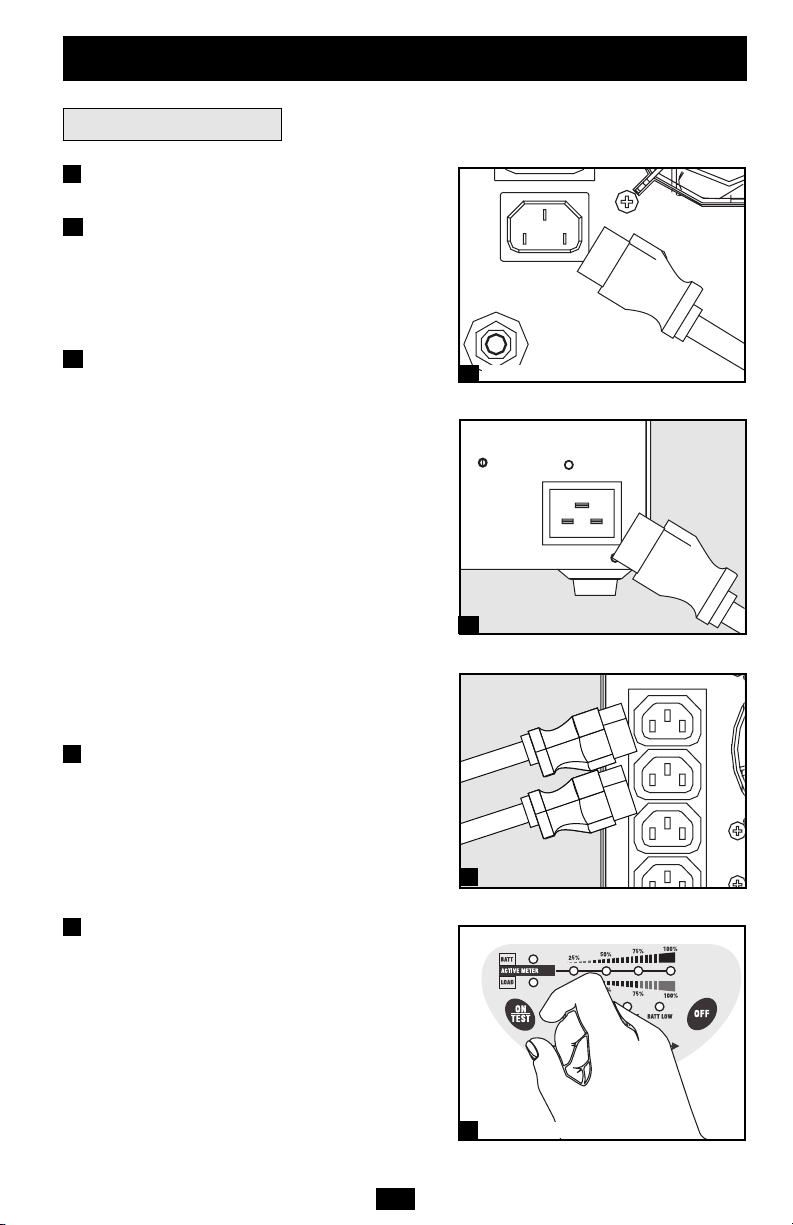
Connection and Start-Up
Plug your UPS into an electrical outlet.
Note: The UPS system does not include an input power cord.
Model SUINT1000XL Only:
Connect a user-supplied power cord to the IEC320-C14 input receptacle. The power cord
should have an IEC-320-C13 connector on one
end and a plug appropriate for your local site’s
utility outlets on the other end.
Models SUINT2000XL and SUINT3000XL
Only:
Connect a user-supplied power cord to the IEC320-C20 input receptacle. The power cord
should have an IEC-320-C19 connector on one
end and a plug appropriate for your local site’s
utility outlets on the other end.
All Models:
Plug the UPS directly into a properly grounded,
3-wire, AC outlet that does not share a circuit
with a heavy electrical load (such as an air conditioner, refrigerator, etc.). The outlet must have
an amp rating equal to or greater than your
UPS’s input breaker rating.
Note: Once your UPS is plugged in, the fan and all Indicator
Lights will turn ON. The “LINE” and “LOAD ACTIVE
METER” LEDs will illuminate and the UPS will beep to indicate normal operation. However, power is not supplied to
your UPS’s AC outlets until the UPS is turned on.
Plug your equipment into your UPS.
Your UPS is designed to support computer
equipment only. You will overload your UPS if
you connect devices with high power demands
such as household appliances or laser printers to
your UPS’s outlets.
Note: Additional interconnection cords (C13 to C14) are available from Tripp Lite. Call 773-869-1234 (Part # P004-006).
Turn your UPS ON:
• Press the “ON/TEST” Switch
• Hold it for several seconds until you hear a beep
• Release it
The “ON LINE” LED will now light, and your
UPS will begin providing power to its AC
outlets.
Note: During the initial installation of the UPS, or after
prolonged storage, the internal batteries must charge for 2-4
hours before the UPS can support connected equipment
during a power failure.
1
2
3
2
3
SUINT2000XL shown
SUINT1000XL shown
1A
1B
SUINT1000XL shown
SUINT2000XL shown
1A
1B
Page 4
Optional Installation
4
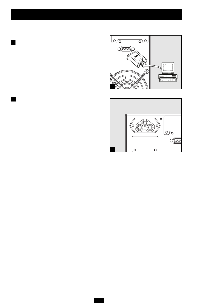
The connections are optional. Your UPS will function properly
without these connections.
Serial Port Connection
Using the serial cable provided, connect the
serial port on your computer to the serial port
of your UPS. Install on your computer the
PowerAlert UPS monitoring software program (included on CD-ROM) appropriate for
your operating system. See Communications
in the Basic Operation section of this manual
to determine how to monitor and manage your
UPS using this port.
External Battery Pack Connection
Check to ensure that the external batteries you
are connecting match the voltage listed on
your UPS’s battery connector. Plug either end
of the battery connection cable (supplied with
the battery pack) into the UPS’s External
Battery Connector and the other end into the
Battery Output Connector on the rear panel of
the external battery pack. Since your UPS has
internal batteries, external batteries are only
needed to extend runtime. Adding external
batteries will increase recharge time as well as
runtime. Make sure that each end of the cable is
fully inserted into its connector. Several small
sparks may result during battery connection;
this is normal.
1
1
SU1000T shown
2
2
SUINT2000XL shown
SUINT2000XL shown
Page 5
5
Important Safety InstructionsBasic Operation
Front Panel Switches
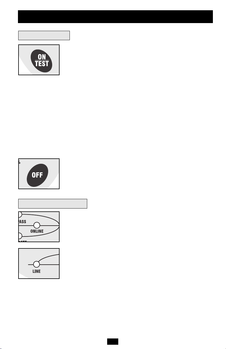
“ON/TEST” Switch: This switch controls four separate UPS functions:
UPS Power ON: To turn the UPS on, press this switch, hold it for
several seconds until you hear a beep, then release it. The “ON LINE”
LED will illuminate.
UPS Self-Test: During normal on-line operation, press this switch
and hold it until you hear a beep. This initiates a 10-second self-test
of the battery. The UPS will shift to battery power (the “ON BATT”
and “BATT ACTIVE METER” LEDs will illuminate) for ten seconds.
Alarm Silence: To silence the UPS “on-battery” alarm, press this
switch and hold it until you hear a beep.
UPS Cold Start: To use your UPS as a stand-alone power source
when AC power is unavailable (i.e. during a blackout), press this
switch and hold it until you hear a beep. The UPS will then provide battery power to its outlets.*
* The “ON BATT” Indicator Light will be illuminated since your UPS will be operating
from battery power.
“OFF” Switch: This switch turns power OFF at the UPS receptacles.
Press this switch, hold it until you hear a beep, then release it. The
UPS will continue charging and the fan will continue to cool internal
components even after you turn the UPS receptacles off. To turn the
UPS OFF completely, including the charger, disconnect the UPS’s
power cord after pressing the “OFF” switch.
“ON LINE” LED: This green light will be lit when the UPS is in normal
on-line operation (filtering and resynthesizing incoming AC line voltage
to provide pure sine wave output). When this light is illuminated, you
can monitor the load level of your UPS on the “LOAD ACTIVE
METER” LEDs.
“LINE” LED: This green light will be lit when the utility-supplied
AC line voltage at your wall outlet is nominal. It will flash if the line
voltage or frequency is outside the nominal range (either too low or
too high). No action is required on your part when the LED flashes;
the UPS continuously and automatically filters AC line power to provide your equipment with pure sine wave AC power, regardless of
brownout or overvoltage conditions. If this light is off, then AC line
voltage is not present (blackout) or is at an extremely high voltage.
Front Panel Indicator Lights
Page 6
Basic Operation
(continued)
6
Front Panel Indicator Lights
continued
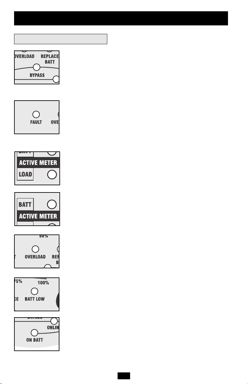
“BYPASS” LED: This yellow light will be lit when the UPS’s
DC/AC inverter is deactivated and the UPS is in the “Bypass” mode.
During normal operation this LED will light briefly when the unit is
plugged in, but if an internal fault or overload occurs this light will
illuminate constantly to show that connected equipment will receive
filtered AC utility power, but will not receive battery power during a
blackout. In this case, contact Tripp Lite for service.
“FAULT” LED: This red light will flash when your UPS detects an
internal fault (overheating, overvoltages, etc.) or when it detects a
wiring fault in your wall outlet (reversed phases, missing ground,
etc.) The UPS will only detect wiring faults when it is plugged into
a utility outlet but not turned ON. If the light persists after restarting
the UPS, contact an electrician to check the AC line. Your UPS will
identify the presence of most (but not all) wiring faults.
“LOAD ACTIVE METER” LED: This green light will illuminate
when your UPS is receiving AC power to indicate that the set of four
dual-function LEDs is displaying the load level of your UPS.
“BATT ACTIVE METER” LED: This green light will be lit when
your UPS is operating from battery power to indicate that the set of
four dual-function LEDs is displaying the battery charge level of your
UPS. The “ON BATT” LED will also be illuminated.
“OVERLOAD” LED: This red light will be lit when your UPS’s capacity has been exceeded while it is in on-line operation. The UPS alarm will
beep continuously. Immediately remove overload until light and alarm
go off. If you do not immediately remove the overload, the UPS will
transfer from on-line to bypass operation.
“BATT LOW” LED: This yellow light will be lit when your UPS’s
battery charge level is low. The UPS alarm will beep until either the
battery charge is depleted or the batteries are adequately recharged.
“ON BATT” LED: This green light will be lit when AC line voltage
is not present and your UPS is providing your equipment with battery
power. The UPS will also beep every two seconds, unless silenced by
the “ON/TEST” Switch. When this light is illuminated, you can monitor
the battery charge level of your UPS on the “BATT ACTIVE
METER” LEDs.
Page 7
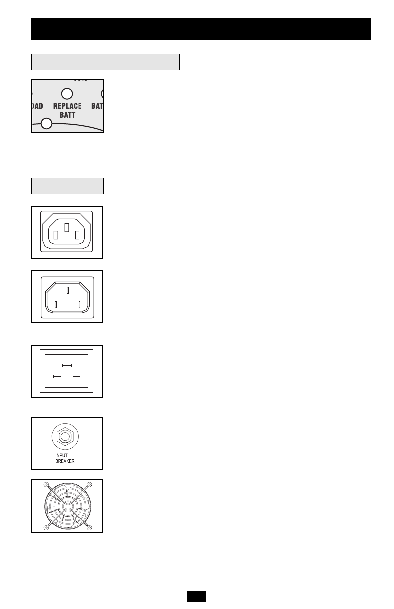
“REPLACE BATT” LED: This red light will be lit and the UPS alarm
will beep every 2 seconds if your UPS’s microprocessor detects a
battery fault or if your UPS fails the automatic self-test (after you turn
your UPS ON) and the UPS battery is less than fully charged. Let the
UPS charge for 12 hours, then perform a second self test (Basic
Operation—UPS Self-Test). If the light continues to stay on, contact
Tripp Lite for service.
AC Receptacles: These receptacles provide your connected equipment
with pure sine-wave AC output from the AC line during normal operation
and from battery power during blackouts and severe brownouts.
Power provided at these outlets is filtered to protect connected equipment
against damaging surges and line noise.
Input Receptacle (Model SUINT1000XL Only): Plug the UPS system into utility power by connecting a user-supplied power cord to the
IEC-320-C14 input receptacle. The power cord should have an IEC320-C13 connector on one end and a plug appropriate for your local
site's utility outlets on the other end. The UPS system does not include
an input power cord.
Input Receptacle (Models SUINT2000XL and SUINT3000XL
Only): Plug the UPS system into utility power by connecting a user-
supplied power cord to the IEC-320-C20 input receptacle. The power
cord should have an IEC-320-C19 connector on one end and a plug
appropriate for your local site's utility outlets on the other end. The
UPS system does not include an input power cord.
Input Circuit Breaker Switch: This resettable breaker prevents high
input current from damaging the UPS or the attached load. If this
breaker trips, make sure your UPS is connected to AC power of the
proper voltage before resetting the circuit breaker by pushing the
breaker switch in.
Fan: The fan cools the UPS’s internal components. It is always on
when line power is present.
7
Basic Operation
(continued)
Rear Panel
Front Panel Indicator Lights
continued
220/230/240V IEC-320-C13
220/230/240V IEC-320-C14
220/230/240V IEC-320-C20
Page 8
Basic Operation
(continued)
8
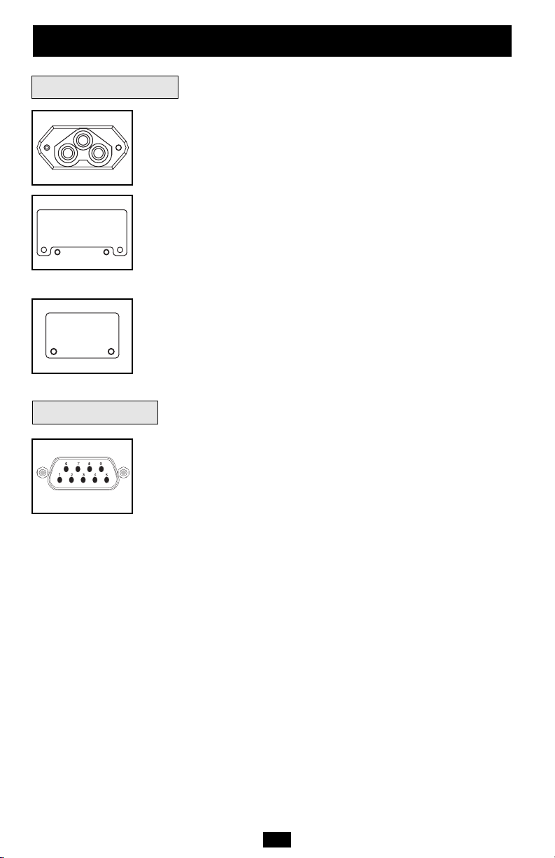
“SMART” DB9 Port: Your UPS’s DB9 port can be used to monitor
and control your UPS using the RS-232 protocol.
RS-232 communications are very complex but are easy to implement.
The easiest way to monitor and control the UPS using RS-232 is to connect
the UPS to a computer with a DB9 cable and install Tripp Lite’s
PowerAlert software on the connected computer.
Communications
Rear Panel
continued
External Battery Pack Connector: Use to connect optional Tripp Lite
Battery Packs for additional runtime. Contact Tripp Lite Customer
Support at (773) 869-1234 for the appropriate Tripp Lite battery pack
to connect. Refer to instructions available with the Battery Pack for
complete connection information and safety warnings.
Accessory Slot (Models SUINT2000XL and SUINT3000XL
Only): Remove the small cover panel from this slot to use optional
accessories to remotely monitor and control your UPS. Contact Tripp
Lite Customer Support at (773) 869-1234 for more information,
including a list of available SNMP, network management and connectivity products.
TVSS Cover Plate: Remove this plate to install optional modem/network
surge protection modules, available for purchase by special arrangement
with Tripp Lite.
Page 9

9
The UPS’s control panel lights will turn on in the sequences below to signal that the UPS is
having operational difficulties.
Lights (On/Flashing) and Condition Solution
On: REPLACE BATT Let the UPS system charge for at least
Condition: Replace Battery 12 hours and perform a self test using
the “ON/Test Switch” (
Basic Operation—
UPS Self-Test
). If the light continues to
stay on, contact Tripp Lite for service.
On: BATT LOW, ON BATT Prepare for imminent UPS shutdown.
Condition: Battery Low
On: BYPASS, LINE, LOAD, OVERLOAD Reduce the load the UPS supports.
Condition: On Bypass due to Overload
Flashing: OVERLOAD Remove the cause of the short circuit
Condition: Short Circuit from the UPS output.
On: FAULT, 100% Restart the UPS. If the problem persists,
Condition: Battery Voltage too High contact Tripp Lite for repairs.
On: FAULT, BYPASS, LINE, 50% Restart the UPS. If the problem persists,
Condition: On Bypass due to contact Tripp Lite for repairs.
High Output Voltage
On: FAULT, BYPASS, LINE Restart the UPS. If the problem persists,
Flashing: 50% contact Tripp Lite for repairs.
Condition: On Bypass due to Low
Bus Voltage
On: FAULT, BYPASS, LINE, 25% Restart the UPS. If the problem persists,
Condition: On Bypass due to contact Tripp Lite for repairs.
Low Output Voltage
On: FAULT, BYPASS, LINE Restart the UPS. If the problem persists,
Flashing: 25% contact Tripp Lite for repairs.
Condition: On Bypass due to Low
Bus Voltage
Troubleshooting
Page 10

Troubleshooting
(continued)
10
Lights (On/Flashing) and Condition Solution
On: BYPASS, LINE Check the UPS to be sure that there is
Flashing: FAULT adequate space for air to circulate near
the vents and that the fan is working
properly. Restart the UPS.
Flashing: LINE This indicates that utility power is too high
Condition: Input Abnormal or low for the UPS to operate in BYPASS
mode, so if an inverter failure occurs,
the UPS will deliver no output.
On: FAULT, 50% Restart the UPS. If the problem persists,
Flashing: LINE contact Tripp Lite for repairs.
Condition: No Output due to High
Output Voltage and Abnormal Input
Flashing: LINE, 50%
Restart the UPS. If the problem persists,
On: FAULT contact Tripp Lite for repairs.
Condition: No Output due to Low
Output Voltage and Abnormal Input
Flashing: LINE, Restart the UPS. If the problem persists,
On: FAULT, 25% contact Tripp Lite for repairs.
Condition: No Output due to High
Bus Voltage and Abnormal Input
Flashing: LINE, 25% Restart the UPS. If the problem persists,
On: FAULT contact Tripp Lite for repairs.
Condition: No Output due to Low
Bus Voltage and Abnormal Input
Flashing: LINE, FAULT Check the UPS to be sure that there is
Condition: No Output due to High adequate space for air to circulate near
Internal Temperature and Abnormal the vents and that the fan is working
Input properly. Restart the UPS. If the problem
persists, contact Tripp Lite for repairs.
Page 11
11
Storage and Service
Storage
Service
First turn your UPS OFF: press the “OFF” switch to turn power off at the UPS outlets, then
disconnect the power cord from the wall outlet. Next, disconnect all equipment to avoid battery
drain. If you plan on storing your UPS for an extended period of time, fully recharge the UPS
batteries once every three months by plugging the UPS into a live AC outlet and letting the
UPS charge for 4-6 hours. If you leave your UPS batteries discharged for an extended period
of time, they may suffer permanent loss of capacity.
Before returning your UPS for service, follow these steps:
1. Review the installation and operation instructions in this manual to ensure that the service
problem does not originate from a misreading of the instructions. Also, check that the UPS
System’s circuit breaker(s) are not tripped. This is the most common cause of service inquiries
which can be easily remedied by following the resetting instructions in this manual.
2. If the problem continues, do not contact or return the UPS to the dealer. Instead, call Tripp
Lite at (773) 869-1233. A service technician will ask for the UPS’s model number, serial number and purchase date and will attempt to correct the problem over the phone.
3. If the problem requires service, the technician will issue you a Returned Material
Authorization (RMA) number, which is required for service. If you require packaging, the
technician can arrange to send you proper packaging. Securely pack the UPS to avoid damage
during shipping. Do not use Styrofoam beads for packaging. Any damages (direct, indirect,
special, incidental or consequential) to the UPS incurred during shipment to Tripp Lite or an
authorized Tripp Lite service center is not covered under warranty. UPS Systems shipped to
Tripp Lite or an authorized Tripp Lite service center must have transportation charges prepaid.
Mark the RMA number on the outside of the package. If the UPS System is within the 2-year
warranty period, enclose a copy of your sales receipt. Return the UPS for service using an
insured carrier to the address given to you by the Tripp Lite service technician.
Note on Labeling
Two symbols are used on the label. V~: AC Voltage V : DC Voltage
Regulatory Compliance Identification Numbers
For the purpose of regulatory compliance certifications and identification, your Tripp Lite product has been assigned a
unique series number. The series number can be found on the product nameplate label, along with all required approval
markings and information. When requesting compliance information for this product, always refer to the series number.
The series number should not be confused with the marking name or model number of the product.
This product designed and engineered in the USA.
Page 12

Manual del usuario
SmartOnline
™
Sistemas UPS inteligentes realmente en línea para montaje en torre
• Operación realmente en línea • Salida sinusoidal pura
• Entrada/salida de 220/230/240V
Modelos: SUINT1000XL, SUINT2000XL y SUINT3000XL
No conveniente para los usos móviles.
Importantes instrucciones de seguridad
13
Instalación
14
Operación básica
16
Almacenamiento y servicio
21
English
Français
23
1
Localización de fallas
20
1111 W. 35 th St re et Ch icago, IL 60609 EE.UU.
Atención al cliente: (773) 869-1234 • www.tripplite.com
© 2006 Tripp Lite. Todos los derechos reservados. SmartOnline es una marca registrada de Tripp Lite.
Operación opcional
15
Page 13

13
Importantes instrucciones de seguridad
Advertencias sobre la colocación del UPS
• Instale el sistema UPS bajo techo, alejado del calor o la humedad excesivos, de los
contaminantes conductivos, del polvo o de la luz solar directa.
• Para lograr el mejor rendimiento, mantenga la temperatura interior entre 0º C y 40º C
(32º F y 104º F).
• Mantenga suficiente espacio alrededor del sistema UPS para permitir una ventilación
adecuada.
Advertencias sobre la conexión del UPS
• Conecte su sistema UPS directamente a una toma de corriente de CA con una conexión a
tierra adecuada. No conecte el sistema UPS a sí mismo, ya que esto lo dañará.
• No modifique los conectores del UPS y no utilice un adaptador que pueda eliminar la
conexión a tierra del sistema.
• No utilice cables de extensión para conectar el UPS en la toma de corriente de CA. Si se
utiliza otro tipo de supresor de sobretensión que no sea Tripp Lite para conectar el UPS a
la toma de corriente, se anulará la garantía del sistema.
• Si el sistema UPS recibe energía eléctrica por medio de un generador de CA accionado
por motor, éste deberá proporcionar una salida de corriente limpia y filtrada del tipo utilizado para computadoras.
Advertencias sobre la conexión de equipos
• No utilice los sistemas UPS de Tripp Lite en equipo para el soporte de la vida humana,
donde un fallo o mal funcionamiento podría causar anomalías o alterar significativamente el rendimiento del dispositivo para el soporte de la vida humana.
• No conecte supresores de sobretensión o cables de extensión a la salida del sistema UPS.
Esto podría dañar el UPS y anularía la garantía del supresor de sobretensiones y del UPS.
Advertencias sobre las baterías
• El sistema UPS no requiere ningún mantenimiento rutinario. No abra el UPS por ningún
motivo, excepto para el reemplazo de las baterías. Esta unidad no contiene partes
internas que puedan ser reparadas por el usuario.
• Debido a los riesgos que presentan las baterías en relación con los choques eléctricos y
las quemaduras causadas por corriente elevada de corto circuito, el personal técnico
capacitado debe observar todas las precauciones pertinentes. Apague y desenchufe el
sistema UPS antes de reemplazar las baterías. Utilice herramientas con asas aisladas y
reemplace las baterías con el mismo número y tipo de baterías nuevas (de plomo-ácido
selladas). No abra las baterías. No permita que ningún objeto entre en contacto con los
terminales de las baterías.
• Las baterías del sistema UPS son reciclables. Consulte el reglamento local para conocer
los requerimientos de desecho aplicables. No utilice fuego para desechar las baterías.
• Conecte únicamente paquetes de baterías Tripp Lite del tipo apropiado y del voltaje
correcto en el conector de baterías externas.
• No conecte ni desconecte las baterías externas cuando el sistema UPS está operando con
baterías.
• No haga funcionar su UPS sin baterías.
GUARDE ESTAS INSTRUCCIONES
Este manual contiene advertencias e instrucciones importantes que deben seguirse
durante la instalación, operación y almacenamiento de todos los sistemas UPS de Tripp Lite.
De no cumplirse estas advertencias, la garantía será anulada.
Page 14

2
1A
1B
14
Instalación
Conexión y encendido
Conecte su UPS en un
tomacorriente.
Nota: El no-break no incluye un cordón de alimentación de
entrada.
Modelo SUINT1000XL solamente:
Conecte un cordón de alimentación suministrado por el usuario en el contacto de entrada IEC320-C14. El cordón de alimentación debe tener
un conector IEC-320-C13 en un extremo y un
enchufe apropiado para las salidas de su servicio
eléctrico local en el otro extremo.
Modelos SUINT2000XL y SUINT3000XL
solamente:
Conecte un cordón de alimentación suministrado por el usuario en el contacto de entrada IEC320-C20. El cordón de alimentación debe tener
un conector IEC-320-C19 en un extremo y un
enchufe apropiado para las salidas de su servicio
eléctrico local en el otro extremo.
Todos los modelos:
Conecte el UPS directamente en una salida
tripolar de CA con el tercer polo correctamente
puesto a tierra, y que no comparta el circuito con
una carga eléctrica pesada (como un equipo de
aire acondicionado, un refrigerador, etc.) La salida debe tener una capacidad igual o mayor que
la del interruptor automático del UPS.
Nota: Una vez que su UPS está enchufado, se encenderá la luz
del ventilador y todas las luces indicadoras. Los LED “LINE”
(Línea) y “LOAD ACTIVE METER” (Medidor activo de
carga) se encenderán y el UPS emitirá un sonido que indica
funcionamiento normal. Sin embargo, no se suministra energía
a las tomas de corriente de CA de su UPS hasta que se éste
encienda.
Enchufe su equipo al sistema UPS.
Su sistema UPS está diseñado para soportar únicamente equipo informático. Usted lo sobrecargará si conecta electrodomésticos o impresoras
láser a las tomas de corriente del UPS.
Nota: Se pueden obtener cables de interconexión adicionales
(C13 a C14) través de Tripp Lite. Llame al 773-869-1234
(Repuesto # P004-006).
1
2
Se muestra SUINT1000XL
Se muestra SUINT2000XL
1A
1B
Se muestra
SUINT2000XL
Page 15

15
3
Se muestra
SUINT1000XL
Instalación opcional
Estas conexiones son opcionales. Este sistema UPS funcionará
correctamente sin estas conexiones.
Conexión de puerto serial
Utilice el cable serial incluido, conecte un puerto serial de su computadora al puerto serial de
su UPS. Instale en su PC el software
PowerAlert (incluido en el CD-ROM) para
control de UPS apropiado para su sistema
operativo. Vea la sección Comunicaciones en
Operación básica de esta manual para
determinar cómo monitorear y administrar el
sistema UPS a través de este puerto.
Conexión del paquete de baterías
externas
Verifique que las baterías externas que desea
conectar tengan el mismo voltaje de la lista
que aparece en el conector para baterías del
UPS. Conecte cualquier extremo del cable de
conexión de batería (proporcionado con el
paquete de baterías) en el conector para
baterías externas del UPS y el otro extremo en
el conector de salida de la batería que se
encuentra en el panel posterior del paquete de
baterías externas.
Debido a que su UPS ya posee baterías internas, las baterías externas son necesarias sólo
para prolongar el tiempo de funcionamiento. Si
agrega baterías externas incrementará el tiempo de recarga así como el tiempo de respaldo.
Asegúrese de que cada extremo del cable esté
completamente insertado en su conector. Es
normal que se produzcan pequeñas chispas
durante la conexión de las baterías.
1
1
SU1000T shown
2
2
Se muestra SUINT2000XL
Se muestra SUINT2000XL
Instalación
(continuación)
Encienda su sistema UPS (ON):
• Presione el interruptor “ON/TEST”
(Encendido/Prueba).
• Manténgalo presionado por varios segundos
hasta que escuche un sonido.
• Suelte el interruptor.
Su sistema UPS empezará a suminastrar energia CA a sus tomas de corriente. Se iluminará
el LED “ON LINE” (En linea).
Nota: Durante la instalación inicial del UPS, o después del
almacenaje prolongado, las baterías internas deben cargar
para 2-4 horas antes de que el UPS puede apoyar el equipo
conectado durante un apagón.
3
Page 16

16
Operación básica
Interruptores del panel frontal
Interruptor “ON/TEST” (Encendido/Prueba): Este interruptor controla cuatro funciones separadas del UPS:
UPS encendido: Para encender el UPS, presione el interruptor, manténgalo presionado por varios segundos hasta que escuche un sonido
y suéltelo. Se encenderá el LED “ON LINE”.
Autoprueba del UPS: Durante una operación en línea normal, presione el interruptor y manténgalo presionado hasta que escuche un
sonido. Esto inicia una autoprueba de la batería que dura 10 segundos. El UPS cambiará a energía de baterías (se iluminarán los LED
“ON BATT” y “BATT ACTIVE METER”) durante diez segundos.
Silenciar alarma: Para silenciar la alarma del UPS “en batería”, presione el interruptor y manténgalo presionado hasta que escuche un
sonido.
Encendido en frío del UPS: Para usar su UPS como una fuente de
energía autónoma cuando no haya energía de CA disponible (es decir,
durante un apagón), presione este botón y manténgalo presionado
hasta que escuche un sonido. El UPS suministrará entonces energía de
las baterías a sus tomas de corriente.*
* La luz indicadora “ON BATT” se iluminará cuando su UPS esté operando con
energía de las baterías.
Interruptor “OFF” (Apagado): Este interruptor apaga el suministro
de energía en los receptáculos del UPS. Presione el interruptor, manténgalo presionado hasta que escuche un sonido y suéltelo. El UPS
seguirá cargando y el ventilador seguirá enfriando los componentes
internos incluso después de haber apagado los receptáculos del UPS.
Para apagar completamente el UPS, incluido el cargador, desconecte
el cable de energía del UPS después de presionar el interruptor
“OFF”.
LED “ON LINE”: Esta luz verde se iluminará y permanecerá fija para
indicar que el UPS está en operación en línea normal (filtrado y resintetizado del voltaje de la línea de CA entrante para proporcionar una
salida en forma de onda sinusoidal pura). Cuando esta luz está encendida, puede controlar el nivel de carga del UPS en los LED “LOAD
ACTIVE METER”.
LED “LINE” (Línea): Esta luz verde se iluminará y permanecerá
fija para indicar que el voltaje de la línea de CA proporcionada por el
suministro en su toma de energía es nominal. La luz parpadeará si el
voltaje de la línea se encuentra fuera del valor nominal (ya sea
demasiado bajo o demasiado alto). No necesita hacer nada cuando el
LED parpadea; el UPS filtra de manera continua y automática la
energía de la línea de CA para suministrar a su equipo energía de CA
de onda sinusoidal pura, sin considerar las condiciones de baja o alza
de voltaje. Si esta luz está apagada, quiere decir que no hay voltaje de
línea de CA (apagón) o que hay un voltaje muy alto y que el UPS proporcionará energía a los equipos conectados desde la batería.
Luces indicadoras del panel frontal
Page 17

17
Operación básica
(continuación)
Luces indicadoras del panel frontal
continuación
LED “BYPASS” (Derivación): Esta luz amarilla se ilumina para
indicar que el inversor de CC/CA del UPS se encuentra desactivado y el
UPS está en el modo “Derivación”. Durante el funcionamiento normal,
este LED se iluminará brevemente al momento de enchufar la unidad,
pero en caso de ocurrir una falla o sobrecarga interna, la luz permanecerá fija para indicar que el equipo conectado recibirá energía
eléctrica de CA filtrada, pero no la energía de las baterías durante un
apagón. En este caso, contáctese con Tripp Lite para obtener servicio
técnico.
LED “FAULT” (Falla): Esta luz roja parpadeará cuando su sistema
UPS detecte una falla interna (sobrecalentamiento, sobrevoltajes, etc.)
o cuando detecte una falla de cableado en las tomas de corriente (fases
invertidas, ausencia de tierra, etc.). El UPS detectará fallas de cableado sólo cuando se encuentre conectado a una toma de energía eléctrica que no esté encendida. Si la luz sigue encendida después de reiniciar el UPS, comuníquese con un electricista para revisar la línea de
CA. Su UPS identificará la mayoría (pero no todas) las fallas de
cableado.
LED “LOAD ACTIVE METER” (Medidor activo de carga): Esta
luz verde se encenderá cuando su UPS reciba energía de CA para
indicar que el grupo de cuatro luces LED de doble funcionalidad está
indicando el nivel de carga de su UPS.
LED “BATT ACTIVE METER” (Medidor activo de batería):
Esta luz verde se encenderá cuando su UPS funcione en base a la
energía de la batería para indicar que el grupo de cuatro luces LED de
doble funcionalidad está mostrando el nivel de carga de la batería de
su UPS. Nota: también se encenderá el LED “ON BATT”.
LED “OVERLOAD” (Sobrecarga): Esta luz roja se iluminará y permanecerá fija para indicar que se excedió la capacidad de su UPS mientras
esté funcionando en línea. La alarma del UPS emitirá un sonido continuo. Retire inmediatamente la sobrecarga hasta que se apague la luz y la
alarma. En caso de no retirar la sobrecarga inmediatamente, el UPS
cambiará de operación en línea a operación de derivación.
LED “BATT LOW” (Batería baja): Esta luz amarilla se encenderá
cuando el nivel de carga de la batería de su UPS esté bajo. La alarma
del UPS emitirá un sonido hasta que la carga de la batería se agote
completamente o se recarguen las baterías de manera adecuada.
LED “ON BATT” (En batería): Esta luz verde se iluminará y permanecerá fija para indicar que no hay voltaje en la línea de CA y que
su UPS está suministrando energía al equipo a través de la batería. El
UPS emitirá un sonido cada dos segundos a menos que lo silencie con
el interruptor “ON/TEST”. Cuando se prende esta luz, puede controlar el nivel de carga de la batería del UPS en los LED “BATT
ACTIVE METER”.
Page 18

18
Operación básica
(continuación)
220/230/240V IEC-320-C13
Panel posterior
LED “REPLACE BATT” (Reemplazar batería): La luz roja se
encenderá, y la alarma del UPS sonará cada 2 segundos si el microprocesador del UPS detecta una falla en la batería o si su UPS falla
en la autoprueba automática (después de encendido) y en caso de que
la batería no esté completamente cargada. Deje que el sistema del
UPS se cargue por lo menos 12 horas y realice una autoprueba usando el interruptor de “ ON/Test ” (Operación básica—Autoprueba del
UPS). Si la luz permanece encendida, póngase en contacto con Tripp
Lite para solicitar servicio técnico.
Receptáculos de CA: Proporcionan a sus equipos conectados
energía de CA de onda sinusoidal pura tomada de la red durante
operación normal y tomada de baterías durante fallas del servicio
eléctrico y bajas de voltaje severas. La energía proporcionada en estas
salidas está filtrada para proteger los equipos conectados contra
sobretensiones perjudiciales y ruido en la línea.
Contacto de entrada (Modelo SUINT1000XL solamente):
Conecte el no-break a la energía de la red mediante un cordón de
alimentación suministrado por el usuario conectado en el contacto de
entrada IEC-320-C14. El cordón de alimentación debe tener un
conector IEC-320-C13 en un extremo y un enchufe apropiado para
las salidas de su servicio eléctrico local en el otro extremo. El
no-break no incluye un cordón de alimentación de entrada.
Contacto de entrada (Modelos SUINT2000XL y SUINT3000XL
solamente): Conecte el no-break a la energía de la red mediante un
cordón de alimentación suministrado por el usuario conectado en el
contacto de entrada IEC-320-C20. El cordón de alimentación debe
tener un conector IEC-320-C19 en un extremo y un enchufe apropiado para las salidas de su servicio eléctrico local en el otro extremo. El
no-break no incluye un cordón de alimentación de entrada.
Interruptor de protección del mando del interruptor de entrada:
Este interruptor reconfigurable evita que una corriente de entrada alta
dañe el UPS o los aparatos conectados a él. Si este interruptor se dispara, asegúrese de que el sistema UPS está conectado a una energía
de CA del voltaje adecuado antes de reconfigurar el interruptor empujándolo hacia adentro.
Ventilador: El ventilador enfría los componentes internos del UPS.
Se encenderá siempre que haya energía de línea presente.
Luces indicadoras del panel frontal
continuación
220/230/240V IEC-320-C14
220/230/240V IEC-320-C20
Page 19

19
Operación básica
(continuación)
Puerto DB9 inteligente: Puede usarse el puerto DB9 del UPS para
monitorear y controlar el UPS usando protocolos RS-232.
Las comunicaciones de RS-232 son muy complejas, pero fáciles de
implementar. La manera más fácil de monitorear y controlar el UPS
usando RS-232 es conectando éste a una computadora con un cable
DB9 e instalar el software PowerAlert de Tripp Lite en la computadora conectada.
Comunicaciones
Panel posterior
continuación
Conector del paquete de baterías externas: Utilícelo para conectar
paquetes de baterías Tripp Lite opcionales si desea tiempo de funcionamiento adicional. Póngase en contacto con el Servicio de atención al cliente de Tripp Lite al (773) 869-1234 para obtener el paquete de baterías Tripp Lite adecuado. Consulte las instrucciones que
vienen con el paquete de baterías para obtener información completa
sobre conexión y advertencias de seguridad.
Ranura para accesorios (Models SUINT2000XL and
SUINT3000XL Only): Retire el pequeño panel que cubre esta ranu-
ra para instalar accesorios opcionales utilizados en el monitoreo y
control remoto del sistema UPS. Póngase en contacto con el Servicio
de atención al cliente de Tripp Lite llamando al (773) 869-1234 para
obtener más información, incluyendo una lista de los productos
disponibles de SNMP, de administración de redes y de conectividad.
Placa de TVSS: Retire esta placa para instalar módulos de protección de
sobrevoltaje para módem/red, disponibles para compra mediante
acuerdo especial con Tripp Lite.
Page 20

20
Localización de fallas
Las luces del panel de control del UPS se encenderán en las secuencias descritas a continuación para indicar que el UPS tiene dificultades de funcionamiento.
Luces (Encendidas/Parpadeando) y condición Solución
Encendidas: REEMPLAZAR BATERÍA Deje que el sistema del UPS se
Condición: Reemplazar batería cargue por lo menos 12 horas y
realice una autoprueba usando el
interruptor de “ ON/Test ” (
Operación
básica—Autoprueba del UPS
). Si la luz
permanece encendida, póngase
en contacto con Tripp Lite para
solicitar servicio técnico.
Encendidas: BATERÍA BAJA, EN BATERÍA Prepárese para un apagado
Condición: Batería baja inminente del UPS.
Encendidas: DERIVACIÓN, LÍNEA, CARGA, Reduzca la carga que soporta
SOBRECARGA el UPS.
Condición: En Derivación por sobrecarga
Parpadeando: SOBRECARGA Retire la causa del cortocircuito
Condición: Cortocircuito de la salida del UPS.
Encendidas: FALLA,100% Reinicie el UPS. Si el problema
Condición: Voltaje de la batería demasiado alto persiste, póngase en contacto
con Tripp Lite para solicitar
servicio técnico.
Encendidas: FALLA, DERIVACIÓN, LÍNEA, 50% Reinicie el UPS. Si el problema
Condición: En derivación debido a sobrevoltaje persiste, póngase en contacto
de salida con Tripp Lite para solicitar
servicio técnico.
Encendidas: FALLA, DERIVACIÓN, LÍNEA Reinicie el UPS. Si el problema
Parpadeando: 50% persiste, póngase en contacto
Condición: En derivación debido a bajo voltaje con Tripp Lite para solicitar
de salida servicio técnico.
Encendidas: FALLA, DERIVACIÓN, LÍNEA, 25% Reinicie el UPS. Si el problema
Condición: En derivación debido a sobrevoltaje persiste, póngase en contacto
en bus con Tripp Lite para solicitar
servicio técnico.
Encendidas: FALLA, DERIVACIÓN, LÍNEA Reinicie el UPS. Si el problema
Parpadeando: 25% persiste, póngase en contacto
Condición: En derivación debido a bajo voltaje con Tripp Lite para solicitar
en bus servicio técnico.
Page 21

21
Localización de fallas
(continuación)
Almacenamiento
Luces (Encendidas/Parpadeando) y condición Solución
Encendidas: DERIVACIÓN, LÍNEA Revise el UPS para asegurarse de que hay
Parpadeando: FALLA suficiente espacio para permitir la
100%, 75% circulación de aire cerca de las ranuras de
Condición: En derivación debido a alta ventilación y que el ventilador esté
temperatura interna funcionando correctamente. Reinicie el UPS.
Parpadeando: LÍNEA Esto indica que el suministro de energía
Condición: Entrada anormal es demasiado alto o bajo para que el UPS
funcione en mod o DERIVACIÓN, de modo
que si ocurre una falla del inversor, el UPS
no entregará energía de salida.
Encendidas: FALLA, 50% Reinicie el UPS. Si el problema
Parpadeando: LÍNEA, persiste, en contacto con Tripp Lite
Condición: No hay salida debido a un para solicitar servicio técnico.
sobrevoltaje de salida y entrada anormal
Parpadeando: LÍNEA, 50% Reinicie el UPS. Si el problema
Encendidas: FALLA, persiste, póngase en contacto
Condición: No hay salida debido a un bajo con Tripp Lite para solicitar
voltaje de salida y entrada anormal servicio técnico.
Parpadeando: LÍNEA, Reinicie el UPS. Si el problema
Encendidas: FALLA, 50% persiste, póngase en contacto
Condición: No hay salida debido a un con Tripp Lite para solicitar
sobrevoltaje en bus y entrada anormal servicio técnico.
Parpadeando: LÍNEA, 25% Reinicie el UPS. Si el problema
Encendidas: FALLA, persiste, póngase en contacto
Condición: No hay salida debido a un bajo con Tripp Lite para solicitar
voltaje en bus y entrada anormal servicio técnico.
Parpadeando: LÍNEA, FALLA Revise el UPS para asegurarse de que hay
Condición: No hay salida debido a una alta suficiente espacio para permitir la
temperatura interna y entrada anormal circulación de aire cerca de las ranuras de
ventilación y que el ventilador esté
funcionando correctamente. Reinicie el UPS.
Si el problema persiste, póngase en contacto
conTripp Lite para solicitar servicio técnico.
Almacenamiento y servicio
Primero, apague el sistema UPS: presione el interruptor “OFF” para desconectar la alimentación en las tomas del UPS, luego desconecte el cable de alimentación de la toma de corriente. Después, desconecte todos sus equipos para evitar el desgaste innecesario de la batería. Si
desea almacenar este sistema UPS por un período prolongado, recargue completamente las
baterías del sistema UPS una vez cada tres meses, conectándolo a una línea de CA que tenga
corriente y permitiéndole que cargue sus baterías por un período de 4 a 6 horas. Si deja las
baterías del sistema UPS descargadas por un periodo de tiempo prolongado, pueden perder su
capacidad en forma permanente.
Page 22

22
Almacenamiento y servicio
(continuación)
Servicio
Antes de enviar su UPS para que le presten servicio, siga los siguientes pasos:
1. Verifique las instrucciones de instalación y operación en este manual para asegurarse que el
problema de servicio no sea causado por una mala interpretación de las instrucciones. Además,
verifique que los interruptores automáticos del UPS no hayan sido disparados. Esta es la causa
más común de pedidos de servicio que pueden ser solucionados fácilmente siguiendo las
instrucciones de restablecimiento en este manual.
2. Si el problema continúa, no contacte con el distribuidor ni devuelva el UPS. En su lugar,
llame a Tripp Lite al (773) 869-1233. Un técnico de servicio le pedirá el modelo, número de
serie y fecha de compra del UPS y tratará de resolver el problema a través del teléfono.
3. Si el problema requiere servicio, el técnico le emitirá un número de Autorización de devolución de mercadería (RMA), necesario para que le presten servicio. Si requiere embalaje, el técnico puede hacer arreglos para que le envíen el embalaje adecuado. Empaque el UPS firmemente para evitar daños durante el despacho. No use camas de Styrofoam para embalaje.
Cualquier daño (directo, indirecto, especial, accidental o resultante) al UPS producido durante
el despacho a Tripp Lite o a un centro autorizado de servicio Tripp Lite no está cubierto por la
garantía. Los sistemas UPS enviados a Tripp Lite o a algún centro de servicio autorizado de
Tripp Lite deben tener los cargos de transporte prepagados. Marque el número RMAen la parte
externa del paquete embalado. Si el UPS está dentro del período de garantía de 2 años, adjunte
una copia de su recibo de compra. Devuelva el UPS para servicio a la dirección dada por el
técnico de Tripp Lite utilizando un transportista asegurado.
Nota sobre el rotulado
Se usan dos símbolos en la etiqueta. V~: Voltaje CA V : Voltaje CC
Cumplimiento de las normas de los números de identificación
Para fines de identificación y certificación del cumplimiento de las normas, su producto Tripp Lite tiene asignado un
número de serie único. Puede encontrar el número de serie en la etiqueta de la placa de identificación del producto,
junto con los símbolos de aprobación e información requeridos. Al solicitar información sobre el cumplimiento de las
normas para este producto, siempre mencione el número de serie. El número de serie no debe ser confundido con el
nombre de identificación ni con el número de modelo del producto.
Este producto ha sido creado y diseqado en EE.UU.
Page 23

Guide de l'utilisateur
SmartOnline
™
Systèmes de tours ASI connectées intelligentes • Fonctionnement réel en ligne
• Puissance de sortie sinusoïdale • Entrée/Sortie 220/230/240V
Modèles : SUINT1000XL, SUINT2000XL & SUINT3000XL
Non approprié aux applications mobiles.
Importantes consignes de sécurité
24
Installation
25
Exploitation de base
27
Entreposage et entretien
33
English
Español
12
1
Dépannage
31
1111 W. 35th Street, Chicago, IL 60609 USA
Service à la clientèle : +1 (773) 869-1234 • www.tripplite.com
© Tripp Lite, 2006. Tous droits réservés. SmartOnline est une marque de commerce de Tripp Lite.
Installation optionelle
26
Page 24

Importantes consignes de sécurité
Mises en garde relatives à l'emplacement du système UPS
• Installez votre système UPS à l'intérieur, loin de l'humidité, de la chaleur excessive, des
impuretés conductrices, de la poussière et de la lumière directe du soleil.
• Pour un meilleur rendement, maintenez la température ambiante entre 0 ºC et 40 ºC
(32 ºF et 104 ºF).
• Laissez suffisamment d'espace autour du système UPS pour maintenir une bonne ventilation.
Mises en garde relatives au raccord du système UPS
• Branchez directement votre système UPS à une prise de courant alternatif munie d'un
contact de mise à la terre. Ne branchez pas votre système UPS sur lui-même car ceci
l'endommagera.
• Ne modifiez pas la prise du système UPS et n’utilisez pas un adaptateur qui rendrait la
connexion de mise à la terre du système inopérante.
• N'utilisez pas de rallonges électriques lors du branchement du système UPS à une prise
c.a. Votre garantie sera annulée si le branchement s'effectue à l'aide de suppresseurs de
surtension autres que ceux fabriqués par Tripp Lite.
• Si votre système UPS est alimenté par une génératrice de courant alternatif, celle-ci devra
fournir un courant filtré et sans parasites convenant au matériel informatique.
Mises en garde relatives au raccord de l'équipement
• Ne raccordez pas les systèmes UPS Tripp Lite à des appareils de soutien vital si leur
dysfonctionnement ou leur défaillance peut causer une panne ou nuire de manière
significative à l'efficacité de ces dispositifs.
• Ne connectez pas de suppresseurs de surtension ou de rallonges électriques à la prise de
votre système UPS. De tels branchements peuvent l’endommager et entraîner une
annulation de sa garantie tout comme celle couvrant le suppresseur de surtension.
Mises en garde relatives à la batterie
• Votre système UPS n'exige pas d'entretien périodique. Ne l'ouvrez pas quelle que soit la
raison sauf pour remplacer la batterie. Aucun composant interne ne peut être réparé par
l’utilisateur.
• Parce que les batteries posent un risque d'électrocution et de brûlure en raison d’une
intensité en court-circuit élevée, veuillez observer les précautions appropriées.
Débranchez et mettez le système UPS hors fonction avant de remplacer les batteries.
Remplacez-les par un nombre identique de batteries du même type (batteries au plomb à
bac hermétique) en utilisant des outils munis de poignées isolantes. N'ouvrez pas les
batteries. Veillez à ce qu'aucun objet ne court-circuite les bornes des batteries.
• Les batteries du système UPS sont recyclables. Veuillez consulter les règlements de votre
localité pour les conditions de recyclage. Ne jetez pas les batteries au feu.
• Ne reliez que des blocs-batteries Tripp Lite de type et de tension appropriés au
connecteur de batterie externe.
• Il ne faut jamais brancher ni débrancher des batteries externes pendant que le système
UPS utilise l’alimentation de la batterie.
• Ne faites pas fonctionner le système UPS sans batteries.
CONSERVEZ CES INSTRUCTIONS EN UN LIEU SÛR
Le présent guide contient des instructions et des mises en garde qui doivent être suivies
lors de l'installation, de l'exploitation et de l'entreposage de tous les systèmes UPS Tripp Lite.
Ne pas tenir compte de ces mises en garde annule la garantie.
24
Page 25

2
1A
1B
25
Installation
Connexion et démarrage
Branchez votre ASI dans une prise
de courant électrique.
Remarque: : L'onduleur UPS ne comprend pas de cordon
d'alimentation.
Modèle SUINT1000XL uniquement :
Connecter un cordon d'alimentation fourni par
l'utilisateur dans la prise d'entrée IEC-320-C14.
Le cordon d'alimentation doit avoir un connecteur IEC-320-C13 à une extrémité et une
fiche adéquate pour les prises de secteur du
service local à l'autre extrémité.
Modèles SUINT2000XL et SUINT3000XL
uniquement :
Connecter un cordon d'alimentation fourni par
l'utilisateur dans la prise d'entrée IEC-320-C20.
Le cordon d'alimentation doit avoir un connecteur IEC-320-C19 à une extrémité et une
fiche adéquate pour les prises de secteur du
service local à l'autre extrémité.
Tous les modèles :
Branchez directement l'ASI à une prise de
courant correctement mise à la terre à 3 fiches,
dont le circuit n'est pas partagé avec une charge
électrique élevée (par exemple, une unité de climatisation, un réfrigérateur, etc.). La prise de
courant doit avoir un calibre d'intensité égal ou
supérieur au calibre d'entrée du disjoncteur de
votre ASI.
Remarque:Une fois le système UPS branché, le ventilateur et
tous les voyants s’allument. Les voyants « LINE »
(ALIMENTATION) et « LOAD ACTIVE METER »
(INDICATEUR DE CHARGE ACTIVE) s’allument et le
système UPS émet un signal sonore pour indiquer qu’il
fonctionne normalement. Les prises c.a. de votre système UPS
ne sont toutefois pas alimentées en courant tant que le système
UPS n’est pas allumé.
Branchez votre matériel dans votre
système UPS.
Votre système UPS n'est conçu que pour
accepter du matériel informatique. Vous
surchargerez votre système UPS si vous
branchez des appareils électroménagers ou des
imprimantes laser à ses prises de courant.
Remarque: Les cordons d'interconnexion (C13 à C14) sont
disponibles chez Tripp Lite. Appelez le 773-869-1234 (Pièce
N° P004-006).
1
2
Modèle SUINT1000XL illustrée
Modèle SUINT2000XL illustré
Modèle
SUINT2000XL illustré
1A
1B
Page 26

26
Ces connexiones sont optionnelles. Votre système UPS
fonctionnera correctement sans ces connexions.
Connexion de port série
En utilisant le câble série fourni, connectez le
port série de votre ordinateur à celui de votre
système UPS. Installez sur votre ordinateur le
logiciel de surveillance ASI PowerAlert
(inclus sur le CD-ROM) qui convient au
système d'exploitation que vous utilisez.
Reportez-vous à la rubrique Communications
de la section Exploitation de base du présent
manuel pour déterminer comment surveiller et
gérer le système UPS à l’aide de ce port.
Branchement d'un bloc-batterie
externe
Assurez-vous que les batteries externes que
vous reliez correspondent à la tension inscrite
sur le connecteur de batterie du système UPS.
Branchez l’une des deux extrémités du câble
de connexion (fourni avec le bloc-batterie)
dans le connecteur de batterie externe du
système UPS et l’autre extrémité dans le
connecteur de sortie de la batterie situé sur le
panneau arrière du bloc-batterie externe.
Puisque votre système UPS dispose de
batteries internes, les batteries externes ne sont
utiles que pour augmenter la durée
d’exécution. L’ajout de batteries externes
allongera le temps de recharge ainsi que la
durée d'exécution. Assurez-vous que chaque
extrémité du câble est complètement insérée
dans son connecteur. Il est normal que la
connexion du bloc-batterie produise de petites
étincelles.
Installation optionnelle
1
1
2
2
Modèle SUINT2000XL
illustré
Modèle SUINT2000XL illustré
Installation
(suite)
Mettez votre système UPS en marche :
• Appuyez sur le commutateur « ON/TEST »
(MARCHE/TEST)
• Maintenez-le enfoncé pendant plusieurs secondes
jusqu’à ce que vous entendiez un signal sonore
• Relâchez-le
Votre système UPS commence à alimenter ses
prises en tension c.a. Le voyant « ON LINE »
(ALIMENTATION) s’allume.
Remarque: Pendant l'installation initiale du système, ou
après stockage prolongé, les batteries internes doivent
chargez pendant 2-4 heures avant que le système peut soutenir
l'équipement relié pendant un arrêt total.
3
3
Modèle SUINT1000XL illustré
Page 27

27
Important Safety InstructionsExploitation de base
Commutateurs du panneau avant
Commutateur « ON/TEST » (MARCHE/TEST) : Le commutateur
commande quatre fonctions distinctes du système UPS :
Mise en fonction du système UPS : Pour allumer le système UPS, appuyez sur
le commutateur et maintenez-le enfoncé pendant plusieurs secondes
jusqu’à ce que vous entendiez un signal sonore puis relâchez-le. Le
voyant « ON LINE » (ALIMENTATION) s’allume.
Autotest du système UPS : En cours d’exploitation en ligne normale,
appuyez sur le commutateur et maintenez-le enfoncé jusqu’à ce que vous
entendiez un signal sonore. Cette procédure lance un autotest de la
batterie d’une durée de 10 secondes. Le système UPS passera en mode
d’exploitation de la batterie [les voyants lumineux « ON BATT »
(BATTERIE EN FONCTION) ET « BATT ACTIVE METER »
(INDICATEUR DE CHARGE DE BATTERIE ACTIVE) s’allument]
pendant 10 secondes.
Interruption de l’alarme : Pour interrompre l’alarme du système UPS
signalant l’exploitation en mode de batterie, appuyez sur le commutateur
et maintenez-le enfoncé jusqu’à ce que vous entendiez un signal sonore.
Démarrage à froid du système UPS : Pour utiliser votre système UPS
comme source d’alimentation autonome lorsque l’alimentation en c.a.
n’est pas disponible (c’est-à-dire durant une panne de courant), appuyez
sur le commutateur et maintenez-le enfoncé jusqu’à ce que vous
entendiez un signal sonore. Le système UPS alimentera ses prises par
l’intermédiaire de sa batterie.*
* Le voyant « ON BATT » (BATTERIE EN FONCTION) s’allume puisque votre
système UPS est alimenté par la batterie.
Commutateur « OFF » (ARRÊT) : Ce commutateur coupe la mise
sous tension des prises de courant du système UPS. Appuyez sur le
commutateur jusqu’à ce que vous entendiez un signal sonore puis
relâchez-le. Le système UPS continuera de charger la batterie et le
ventilateur continuera de refroidir les composants internes après que vous
aurez coupé la mise sous tension des prises du système UPS. Pour couper
complètement l’alimentation du système UPS, y compris l’alimentation
du chargeur, débranchez le cordon d’alimentation après avoir appuyé sur
le commutateur « OFF » (ARRÊT).
VOYANT DEL « ON LINE » (ALIMENTATION) : Ce voyant vert
s’allume constamment pour signaler que le système UPS fonctionne
normalement en mode d’exploitation en ligne (en filtrant et en
resynthétisant la tension de ligne à c.a.. pour fournir une onde sinusoïdale
de sortie pure). Lorsque ce voyant est allumé, vous pouvez surveiller le
niveau de charge de la batterie de votre système UPS à l’aide des voyants
DEL « LOAD ACTIVE METER » (INDICATEUR DE CHARGE ACTIVE).
VOYANT DEL « LINE » (ALIMENTATION) : Ce voyant vert
s’allume constamment pour indiquer que la tension de la ligne à c.a. de la
prise murale est nominale. Il clignote si la tension de ligne se situe à
l’extérieur de la plage nominale (si elle est trop basse ou trop élevée).
Aucune action ne doit être prise de votre part si les voyants DEL
clignotent; le système UPS filtre automatiquement et continuellement la
ligne à c.a. pour fournir une onde sinusoïdale pure en tension c.a., peu
importe les baisses de tension ou les surtensions. Si le voyant est éteint, la
tension de la ligne à c.a. n’alimente pas le système (panne de courant) ou
présente une tension extrêmement élevée. Le système UPS alimente alors
l’équipement à partir de la batterie.
Voyants du panneau avant
Page 28

28
Exploitation de base
(suite)
Voyants du panneau avant
suite
VOYANT « BYPASS » (ÉVITEMENT) : Ce voyant jaune s’allume
pour signaler que le convertisseur c.c./c.a. est désactivé et que le système
UPS est en mode d’évitement. En cours de fonctionnement normal, ce
voyant DEL s’allume brièvement lorsque l’appareil est branché.
Toutefois, si une défaillance interne ou une surcharge se produit, il
s’allume en continu pour indiquer que l’équipement branché reçoit du
courant c.a. filtré du secteur, mais pas l’alimentation électrique de la
batterie en cas de panne. En pareil cas, communiquez avec le service à la
clientèle de Tripp Lite.
VOYANT DEL « FAULT » (DÉFAILLANCE) : Ce voyant rouge
clignote lorsque le système UPS détecte une défaillance interne
(surchauffe, surtensions, etc.) ou un problème de câblage dans les prises
murales (phases inversées, absence de mise à la terre, etc.) Le système
UPS ne détecte les problèmes de câblage que lorsqu’il est branché dans
une prise de courant, mais qu’il n’est pas allumé. Si le voyant ne s’éteint
pas après avoir redémarré le système UPS, communiquez avec un
électricien pour qu’il vérifie la ligne à c.a. Votre système UPS est en
mesure de détecter la présence de la plupart des problèmes de câblage,
mais pas tous.
VOYANT DEL « LOAD ACTIVE METER » (INDICATEUR DE
CHARGE ACTIVE) : Ce voyant vert s’allume lorsque le système UPS
reçoit de l’alimentation électrique en courant alternatif pour indiquer que
le jeu des quatre voyants à double fonction affichent le niveau de charge
de votre système UPS.
VOYANT DEL « BATT ACTIVE METER » (CHARGE DE
BATTERIE ACTIVE) : Ce voyant vert s’allume lorsque le système UPS
reçoit de l’alimentation électrique de la batterie pour indiquer que le jeu
des quatre voyants DEL à double fonction affichent le niveau de charge de
la batterie de votre système UPS. Remarque : le voyant DEL « ON
BATT » (BATTERIE EN FONCTION) s’allume aussi.
VOYANT DEL « OVERLOAD » (SURCHARGE) : Ce voyant rouge
s’allume constamment pour indiquer que la capacité de votre système
UPS a été dépassée lorsqu’il fournit une exploitation en ligne. L’alarme
sonore du système UPS retentit continuellement. Éliminez immédiatement
la surcharge jusqu’à ce que le voyant et l’alarme s’éteignent. Si vous ne
supprimez pas immédiatement la surcharge, le système UPS passera de
l’exploitation en ligne à l’exploitation en mode d’évitement.
VOYANT « BATT LOW » (CHARGE FAIBLE) : Ce voyant jaune
s’allume lorsque la charge de la batterie du système UPS est faible. L’alarme
sonore du système UPS retentit jusqu’à ce que la charge de la batterie soit
épuisée ou que les batteries soient adéquatement rechargées.
VOYANT DEL « ON BATT » (BATTERIE EN FONCTION) : Ce
témoin vert s’allume constamment pour indiquer que la tension de ligne à
c.a. n’est pas présente et que le système UPS alimente votre matériel à
l’aide de la charge de la batterie. Le système UPS se fera également
entendre à
toutes les deux secondes, à moins qu’il soit interrompu à l’aide du
commutateur « ON/TEST » (MARCHE/TEST). Lorsque ce voyant est
allumé, vous pouvez surveiller le niveau de charge de la batterie de votre
système UPS à l’aide des voyants DEL « BATT ACTIVE METER »
(INDICATEUR DE BATTERIE ACTIVE).
Page 29

29
VOYANT DEL « REPLACE BATT » (REMPLACER LA
BATTERIE) : Ce voyant rouge s'illuminera et l'alarme de l'UPS
retentira toutes les 2 secondes si le microprocesseur du système UPS
détecte une défaillance de batterie ou si l’autotest du système UPS
échoue (après que vous allumez votre système UPS) et que la batterie
du système UPS n’est pas complètement chargée. Laisser l'UPS
recharger pendant au moins 12 heures et effectuer un auto-test en
utilisant le commutateur “ON/Test” (Exploitation de base—Autotest
du système UPS). Si le voyant est toujours allumé, communiquez avec
le service à la clientèle de Tripp Lite.
Prises d'alimentation c.a. Ces prises alimentent l'équipement branché
avec une puissance de sortie sinusoïdale à partir de la ligne c.a. pendant
le fonctionnement normal et avec les piles pendant les pannes d'électricité et lorsque l'éclairage est réduit. L'énergie fournie à ces prises est filtrée
pour protéger l'équipement branché des surtensions et du bruit de ligne
pouvant l'endommager.
Prise d'entrée (Modèle SUINT1000XL uniquement) : Brancher
l'onduleur au secteur en connectant un cordon d'alimentation fourni par
l'utilisateur dans la prise d'entrée IEC-320-C14. Le cordon d'alimentation doit avoir un connecteur IEC-320-C13 à une extrémité et une
fiche adéquate pour les prises de secteur du service local à l'autre
extrémité. L'onduleur UPS ne comprend pas de cordon d'alimentation.
Prise d'entrée (Modèles SUINT2000XL et SUINT3000XLuniquement) : Brancher l'onduleur au secteur en connectant un cordon d'al-
imentation fourni par l'utilisateur dans la prise d'entrée IEC-320-C20.
Le cordon d'alimentation doit avoir un connecteur IEC-320-C19 à une
extrémité et une fiche adéquate pour les prises de secteur du service
local à l'autre extrémité. L'onduleur UPS ne comprend pas de cordon
d'alimentation.
Commutateur de disjoncteur du circuit d’entrée : Ce disjoncteur
à réenclenchement empêche que du courant d'entrée élevé endommage le système UPS ainsi que le matériel qui y est branché. Si ce disjoncteur se déclenche, assurez-vous que votre système UPS est
branché à une prise d’alimentation en c.a. d’une tension appropriée
avant de réarmer le disjoncteur en appuyant sur son commutateur.
Ventilateur : Le ventilateur refroidit les composants internes du système UPS. Il est toujours en fonction lorsque l’alimentation secteur
est présente.
Exploitation de base
(suite)
Panneau arrière
Voyants du panneau avant
suite
220/230/240V IEC-320-C13
220/230/240V IEC-320-C14
220/230/240V IEC-320-C20
Page 30

30
Exploitation de base
(suite)
Port série DB9 intelligent : Le port DB9 du système UPS peut être
utilisé pour surveiller et gérer le système UPS à l’aide des protocoles
de communication RS-232. Les communications par protocoles RS232 sont très complexes, mais faciles à mettre en oeuvre. La façon la
plus simple de surveiller et de gérer le système UPS en utilisant le
protocole RS-232 est de brancher votre système UPS à un ordinateur
à l’aide d’un câble DB9 et d’installer le logiciel PowerAlert de Tripp
Lite sur l’ordinateur branché.
Communications
Panneau arrière
suite
Connecteur pour bloc-batterie externe : Utilisez-le pour relier des
blocs-batteries Tripp Lite supplémentaires de manière à augmenter la
durée d'exécution. Communiquez avec le service à la clientèle de
Tripp Lite au (773) 869-1234 pour connaître le bloc-batterie Tripp Lite
approprié à brancher. Consultez le guide de l'utilisateur fourni avec le
bloc-batterie externe pour les instructions complètes relatives à son
installation et les précautions à prendre.
Fente à accessoires (Models SUINT2000XL and SUINT3000XL
Only) : Enlevez le petit volet de cette fente pour installer des acces-
soires optionnels de surveillance et de gestion de votre système UPS.
Communiquez avec le service à la clientèle de Tripp Lite au (773)
869-1234 pour plus de détails, incluant une liste des produits SNMP,
de gestion de réseau et de connectivité offerts.
Couvercle du bloc TVSS : Retirez ce couvercle pour installer les
modules de protection contre la surtension pour les modems et les
réseaux qui peuvent être achetés en prenant des dispositions spéciales
avec Tripp Lite.
Page 31

31
Les voyants du panneau de configuration du système UPS s’allument selon la séquence ci-dessous pour
indiquer que le système UPS ne fonctionne pas normalement.
Voyants (allumés/clignotent) et problème Solution
Allumés : REPLACE BATT(REMPLACER Laisser l'UPS recharger pendant
LA BATTERIE) au moins 12 heures et effectuer un
Problème : Remplacez la batterie. auto-test en utilisant le commutateur
“ON/Test” (
Exploitation de base—
Autotest du système UPS
). Si le
voyant est toujours allumé,
communiquez avec le service à la
clientèle de Tripp Lite.
Allumés : BATT LOW, ON BATT (BATTERIE Attendez-vous à ce que le système
FAIBLE, BATTERIE EN FONCTION) UPS cesse de fonctionner sous peu.
Problème : Batterie faible
Allumés : BYPASS, LINE, LOAD, OVERLOAD Réduisez la charge du système UPS.
(ÉVITEMENT, ALIMENTATION, CHARGE,
SURCHARGE)
Problème : En mode d’évitement en raison
d’une surcharge
Clignotent : OVERLOAD (SURCHARGE) Corrigez la cause du court-circuit
Problème : Court-circuit à la sortie du système UPS.
Allumés : FAULT, 100% Redémarrez le système UPS. Si le
(DÉFAILLANCE, REMPLACER LA BATTERIE) problème persiste, consultez le
Problème :Tension de la batterie trop élevée service à la clientèle de Tripp Lite.
Allumés : FAULT, BYPASS, LINE (DÉFAILLANCE, Redémarrez le système UPS. Si le
ÉVITEMENT, ALIMENTATION), 50 % problème persiste, consultez le
Problème : En mode d’évitement en raison service à la clientèle de Tripp Lite.
d’une tension de sortie élevée
Allumés : FAULT, BYPASS, LINE (DÉFAILLANCE, Redémarrez le système UPS. Si le
ÉVITEMENT, ALIMENTATION) Clignotent : 50 % problème persiste, consultez le
Problème : En mode d’évitement en raison service à la clientèle de Tripp Lite.
d’une tension de sortie basse
Allumés : FAULT, BYPASS, LINE (DÉFAILLANCE, Redémarrez le système UPS. Si le
ÉVITEMENT, ALIMENTATION), 25 % problème persiste, consultez le
Problème : En mode d’évitement en raison service à la clientèle de Tripp Lite.
d’une tension de source élevée
Dépannage
Page 32

32
Dépannage
(suite)
Voyants (allumés/clignotent) et problème Solution
Allumés : FAULT, BYPASS, LINE (DÉFAILLANCE, Redémarrez le système UPS. Si le
ÉVITEMENT, ALIMENTATION) problème persiste, consultez le
Clignotent : 25 % service à la clientèle de Tripp Lite.
Problème : En mode d’évitement en raison
d’une tension de source basse
Allumés : BYPASS, LINE (ÉVITEMENT, ALIMENTATION) Assurez-vous qu’il y a suffisamment
Clignotent : FAULT (DÉFAILLANCE) d’espace autour du système UPS
Problème : En mode d’évitement en raison pour que l’air circule près des
d’une température interne élevée évents et que le ventilateur
fonctionne correctement. Redémarrez
le système UPS.
Clignotent : LINE (ALIMENTATION) Cela indique que la puissance
Problème : Entrée anormale électrique est trop élevée ou trop
basse pour que le système UPS
puisse fonctionner en mode
d’évitement. Si un convertisseur
tombe en panne, le système
UPS ne pourra pas alimenter le
matériel qui y est branché.
Allumés : FAULT (DÉFAILLANCE), 50 % Redémarrez le système. Si le
Clignotent : LINE, (ALIMENTATION) problème persiste, consultez le
Problème : Aucune sortie en raison d’une service à la clientèle de Tripp Lite.
tension de sortie élevée et d’une entrée anormale
Clignotent : LINE, 50 % (ALIMENTATION, Redémarrez le système UPS. Si le
50 % problème persiste, consultez le
Allumés : DÉFAILLANCE (FAULT), service à la clientèle de Tripp Lite.
Problème : Aucune sortie en raison d’une
tension de sortie faible et d’une entrée anormale
Clignotent : LINE, (ALIMENTATION,) Redémarrez le système UPS. Si le
Allumés : FAULT (DÉFAILLANCE), 50 % problème persiste, consultez le
Problème : Aucune sortie en raison d’une tension service à la clientèle de Tripp Lite.
de source élevée et d’une entrée anormale
Clignotent : LINE, 25 % (ALIMENTATION,) Redémarrez le système ups. Si le
25 % problème persiste, consultez le
Allumés : FAULT (DÉFAILLANCE), service à la clientèle de Tripp Lite.
Problème : Aucune sortie en raison d’une tension
de source basse et d’une entrée anormale
Clignotent : LINE, FAULT (DÉFAILLANCE), Assurez-vous qu’il y a suffisamment
(ALIMENTATION) FAULT (DÉFAILLANCE), d’espace autour du système UPS
Problème : Aucune sortie en raison d’une pour que l’air circule près des évents
température interne élevée et d’une entrée anormale et que le ventilateur fonctionne
correctement. Redémarrez le
système UPS. Si le problème
persiste, consultez le service à la
clientèle de Tripp Lite.
Page 33

33
Entreposage et entretien
Veuillez d’abord éteindre votre système UPS : appuyez sur le commutateur « OFF »
(ARRÊT) pour couper l’alimentation électrique au niveau des prises du système UPS puis
débranchez le cordon d’alimentation de la prise murale. Débranchez ensuite tout le matériel pour
éviter d’épuiser la batterie. Si vous envisagez d'entreposer votre système UPS pour une période
prolongée, rechargez complètement les batteries à tous les trois mois en branchant le système à
une prise de secteur pendant 4 ou 6 heures. Si vous laissez les batteries de votre système UPS
déchargées pendant une période de temps extrêmement longue, elles souffriront d'une perte
permanente de capacité.
Avant d'envoyer votre UPS pour réparations, suivre ces étapes ;
1. Relire les directives d'installation et de fonctionnement dans ce manuel pour vous assurer
que le problème n'a pas pour origine une mauvaise lecture des directives. Vérifier également
que les disjoncteurs du circuit du système UPS n'ont pas sauté. C'est la cause la plus courante
des demandes de service; on peut y remédier facilement en suivant les directives de remise en
marche dans ce manuel.
2. Si le problème persiste, ne pas communiquer ou renvoyer l'UPS au vendeur. À la place,
appeler Tripp Lite au (773) 869-1233. Un technicien des réparations vous demandera le
numéro de modèle de l'UPS, son numéro de série et sa date d'achat et essaiera de régler le
problème au téléphone.
3. Si le problème nécessite une réparation, le technicien vous émettra un numéro d'autorisation
de retour de matériel (RMA) qui est exigée pour une réparation. Si vous avez besoin d'un
emballage, le technicien peut vous faire envoyer un emballage approprié. Emballer
soigneusement l'UPS pour éviter des dommages pendant l'expédition. Ne pas utiliser de billes
de styrofoam pour emballer. Tout dommage (direct, indirect, spécial, accidentel ou fortuit)
arrivé à l'UPS pendant le transport à Tripp Lite ou à un centre de service autorisé Tripp Lite est
exclu de la garantie. Les frais de transport des systèmes UPS envoyés à Tripp Lite ou à un
centre de service autorisé Tripp Lite doivent être prépayés. Inscrire le numéro de RMA sur le
paquet. Si l'UPS est encore couvert par la garantie de deux ans, joindre une copie de votre
facture d'achat. Renvoyer l'UPS pour réparation par un transporteur assuré à l'adresse que vous
a donnée le technicien de service de Tripp Lite.
Entreposage
Entretien
Note sur l'étiquetage
Deux symboles sont utilisés sur l'étiquette. V~:Voltage c.a. V : Voltage c.c.
Numéros d'identification de conformité aux règlements
À des fins de certification et d'identification de conformité aux règlements, votre produit Tripp Lite a reçu un
numéro de série unique. Ce numéro se retrouve sur la plaque signalétique du produit, avec les inscriptions et informations d'approbation requises. Lors d'une demande d'information de conformité pour ce produit, utilisez toujours
le numéro de série. Il ne doit pas être confondu avec le nom de la marque ou le numéro de modèle du produit.
Ce produit a été conçu et fabriqué aux États-Unis.
Page 34

34
Page 35

35
Page 36

200602179 93-2525
1111 W. 35th Street Chicago, IL 60609 USA
Customer Support: (773) 869-1234 • www.tripplite.com
 Loading...