

Page 1

Owner’s Manual
SmartPro® 2U Rackmount
Intelligent, Line-Interactive UPS Systems
230V Sine Wave Output • 1000VA—3000VA Capacities
SMX1000RT2U
(Series Number: AG-0072)
SMX1500XLRT2U
(Series Number: AG-0071)
Extended Runtime Options
SMX2200XLRT2U
(Series Number: AG-0070)
SMX3000XLRT2UA
(Series Number: AG-0069)
Not suitable for mobile applications.
Important Safety Instructions 2
Mounting 4
Quick Installation 6
Optional Installation 7
Basic Operation 9
Storage and Service 17
Battery Replacement 18
Warranty Registration 24
Español 25
Français 49
Русский 73
Deutsch 97
PROTECT YOUR INVESTMENT!
Register your product for quicker service
and ultimate peace of mind.
You could also win an ISOBAR6ULTRA
surge protector—a $100 value!
www.tripplite.com/warranty
1111 W. 35th Street, Chicago, IL 60609 USA • www.tripplite.com/support
Copyright © 2018 Tripp Lite. All rights reserved. SmartPro® is a registered trademark of Tripp Lite.
18-09-245-933184.indb 1 12/21/2018 11:07:19 AM
1
Page 2

Important Safety Instructions
SAVE THESE INSTRUCTIONS
This manual contains important instructions that should be followed during the installation,
operation and storage of this product. Failure to heed these warnings may affect the warranty.
UPS Location Warnings
• Use caution when lifting the UPS. Because of the considerable weight of all rackmount UPS
systems, at least two people should assist in lifting and installing them.
• Install the UPS indoors, away from excess moisture or heat, dust or direct sunlight.
• For best performance, the ambient temperature near the UPS should be between 0° C and 40° C
(between 32° F and 104° F).
• Leave adequate space around all sides of the UPS for proper ventilation. Do not obstruct its vents
or fan openings.
• When mounting the UPS system in a tower orientation, make sure the LCD Screen panel is at the
top of the UPS, not at the bottom.
• Do not mount unit with its front or rear panel facing down (at any angle). Mounting in this manner
will seriously inhibit the unit’s internal cooling, eventually causing product damage not covered
under warranty.
UPS Connection Warnings
• The UPS contains its own energy source (battery). The output terminals may be live even when
the UPS is not connected to an AC supply.
• Connect the UPS to a properly grounded AC power outlet. Do not modify the UPS’s plug in a way
that would eliminate the UPS’s connection to ground. Do not use adapters that eliminate the
UPS’s connection to ground.
• The power outlet that supplies the UPS should be installed near the UPS and be easily
accessible.
• Do not plug the UPS into itself; this will damage the UPS and void your warranty.
• If you are connecting the UPS to a motor-powered AC generator, the generator must provide
filtered, frequency-regulated computer-grade output. Connecting the UPS to a generator will void
its Ultimate Lifetime Insurance.
Equipment Connection Warnings
• Use of this equipment in life support applications where failure of this equipment can reasonably
be expected to cause the failure of the life support equipment or to significantly affect its safety
or effectiveness is not recommended. Do not use this equipment in the presence of a flammable
anesthetic mixture with air, oxygen or nitrous oxide.
• Do not connect surge suppressors or extension cords to the output of the UPS. This might
damage the UPS and may affect the surge suppressor and UPS warranties.
2
18-09-245-933184.indb 2 12/21/2018 11:07:19 AM
Page 3

Important Safety Instructions
Battery Warnings
• Batteries can present a risk of electrical shock and burn from high short-circuit current. Observe
proper precautions. Do not dispose of the batteries in a fire. Do not open the UPS or batteries.
Do not short or bridge the battery terminals with any object. Unplug and turn off the UPS before
performing battery replacement. Use tools with insulated handles. There are no user-serviceable
parts inside the UPS. Battery replacement should be performed only by authorized service
personnel using the same number and type of batteries (Sealed Lead-Acid). The batteries
are recyclable. Refer to your local codes for disposal requirements or visit www.tripplite.com/
UPSbatteryrecycling for recycling information. Tripp Lite offers a complete line of UPS System
Replacement Battery Cartridges (R.B.C.).Visit Tripp Lite on the Web at www.tripplite.com/support/
battery/index.cfm to locate the specific replacement battery for your UPS. The RBC Type can
also be found on the label affixed to the Battery Retention Plate.
• During hot-swap battery replacement, the UPS will not provide backup power in the event of a
blackout or other power interruptions.
• Do not operate the UPS without batteries.
External Battery Connection Warnings
• When adding external battery packs to select models with external battery pack connectors,
connect only Tripp Lite-recommended battery packs of the correct voltage and type. Do not
connect or disconnect battery packs when the UPS is operating on battery power.
Visit www.tripplite.com/support/battery/index.cfm to locate the supported battery type(s) for
your UPS.
3
18-09-245-933184.indb 3 12/21/2018 11:07:19 AM
Page 4
Mounting (Rack)
Mount your equipment in either a 2-post or 4-post rack or rack enclosure. The user must
determine the fitness of hardware and procedures before mounting. If hardware and procedures
are not suitable for your application, contact the manufacturer of your rack or rack enclosure. The
procedures described in this manual are for common rack and rack enclosure types and may not
be appropriate for all applications.
Note: The illustrations may differ from your model.
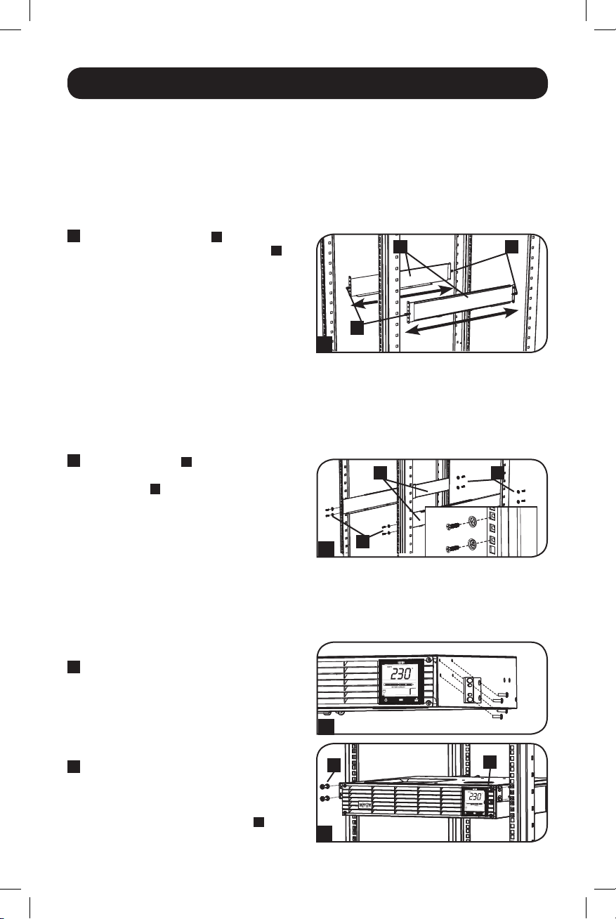
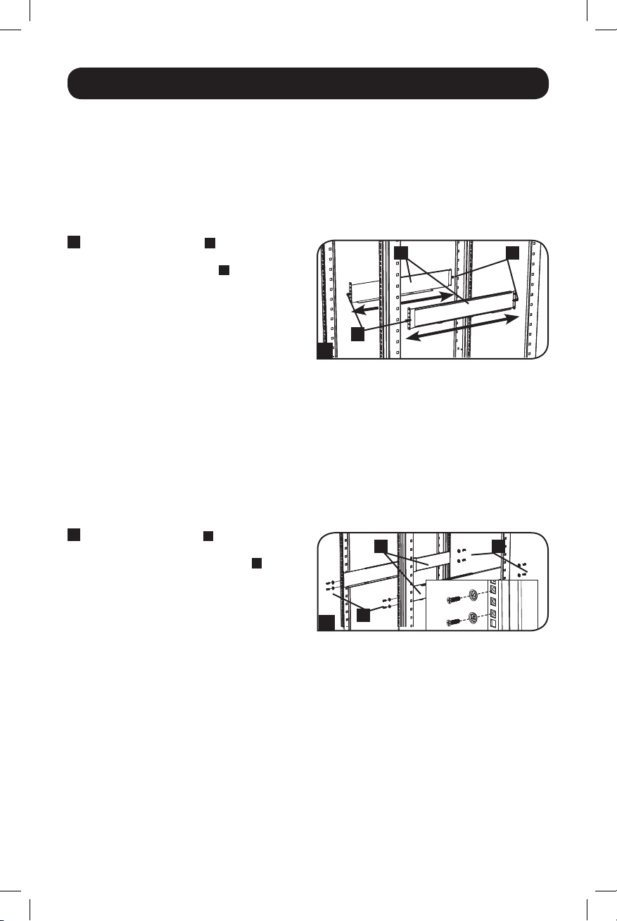
4-Post Mounting
1
The included plastic pegs
support the empty rackmount shelves
while you install the permanent mounting
hardware. Insert a peg near the center of
the front and rear bracket of each shelf as
shown. (Each front bracket has 6 holes and
each rear bracket has 3 holes.) The pegs
will snap into place.
After installing the pegs, expand each shelf
to match the depth of your rack rails. The
pegs will fit through the square holes in the
rack rails to support the shelves. Refer to
the rack unit labels to confirm that the
shelves are level in all directions. Note: The
support ledge of each shelf must face
inward.
2
Secure the shelves
permanently using the included screws and
cup washers
washer between the screw and the rack so
that the screw enters the wider opening of
the cup washer first.
Place 4 screws total at the front and 4
screws total at the back.
Tighten all screws before proceeding.
Warning: Do not attempt to install your
equipment until you have inserted and
tightened the required screws. The
plastic pegs will not support the weight
of your equipment.
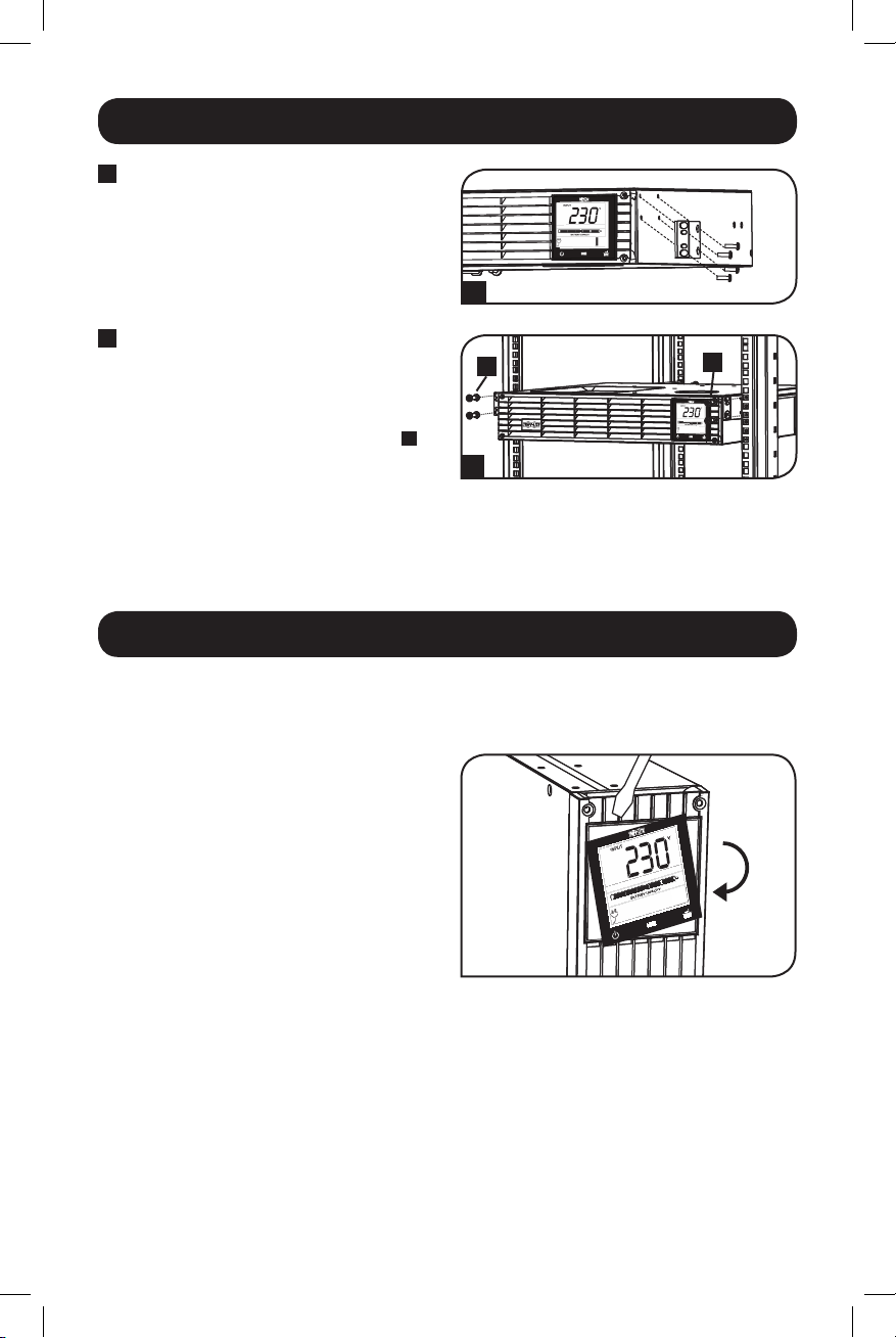
3
Attach your equipment’s mounting brackets
to the forward mounting holes of the
cabinet using the hardware included with
your equipment. The mounting bracket
“ears” should face forward. (Some
equipment may have pre-installed or
integral mounting brackets.)
4
With the aid of an assistant (if necessary),
lift your equipment and slide it into the
shelves. Attach the equipment mounting
brackets to the forward mounting rails with
user-supplied screws and washers
Tighten all screws securely.
C
as shown. Place the cup
A
will temporarily
B
to the mounting rails
D
B
AB
A
1
CB
C
2
3
D
.
D
4
4
18-09-245-933184.indb 4 12/21/2018 11:07:21 AM
Page 5
Mounting (Rack) continued
2-Post Mounting
2-post mounting requires a Tripp Lite 2-Post Rackmount Installation Kit (model: 2POSTRMKITWM,
sold separately).
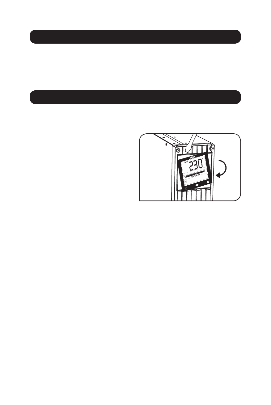
Mounting (Tower)
Warning: When mounting the UPS system in a tower orientation, make sure the LCD
Screen panel is at the top of the UPS, not at the bottom.
Note: To mount the UPS in an upright (tower) position, 2-9USTAND is required (sold separately).
Rotate the LCD Screen panel for easy viewing
while the UPS is tower mounted. Insert a small
screwdriver, or other tool, in the slots on either
side of the panel. Pop the panel out, rotate it
and pop the panel back in place.
5
18-09-245-933184.indb 5 12/21/2018 11:07:22 AM
Page 6
Quick Installation
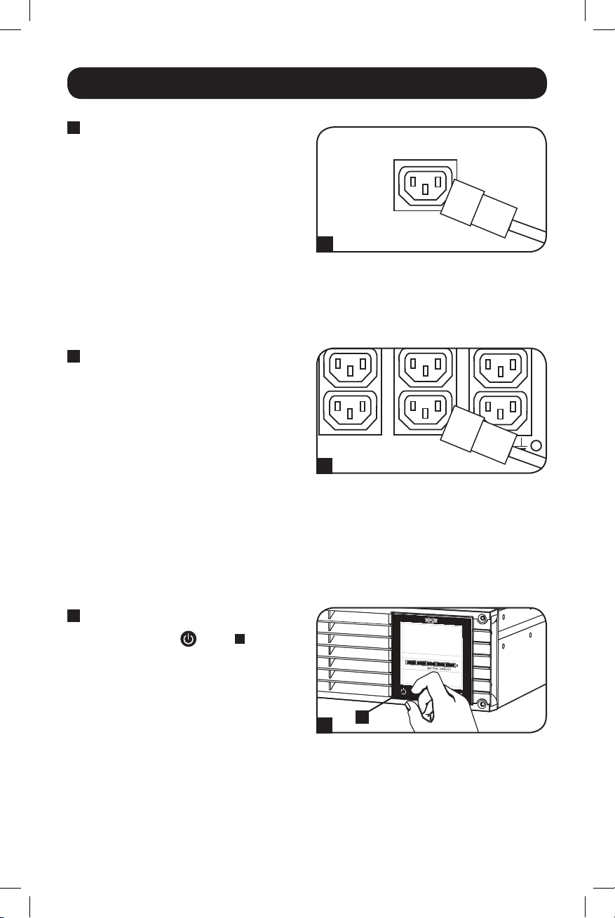
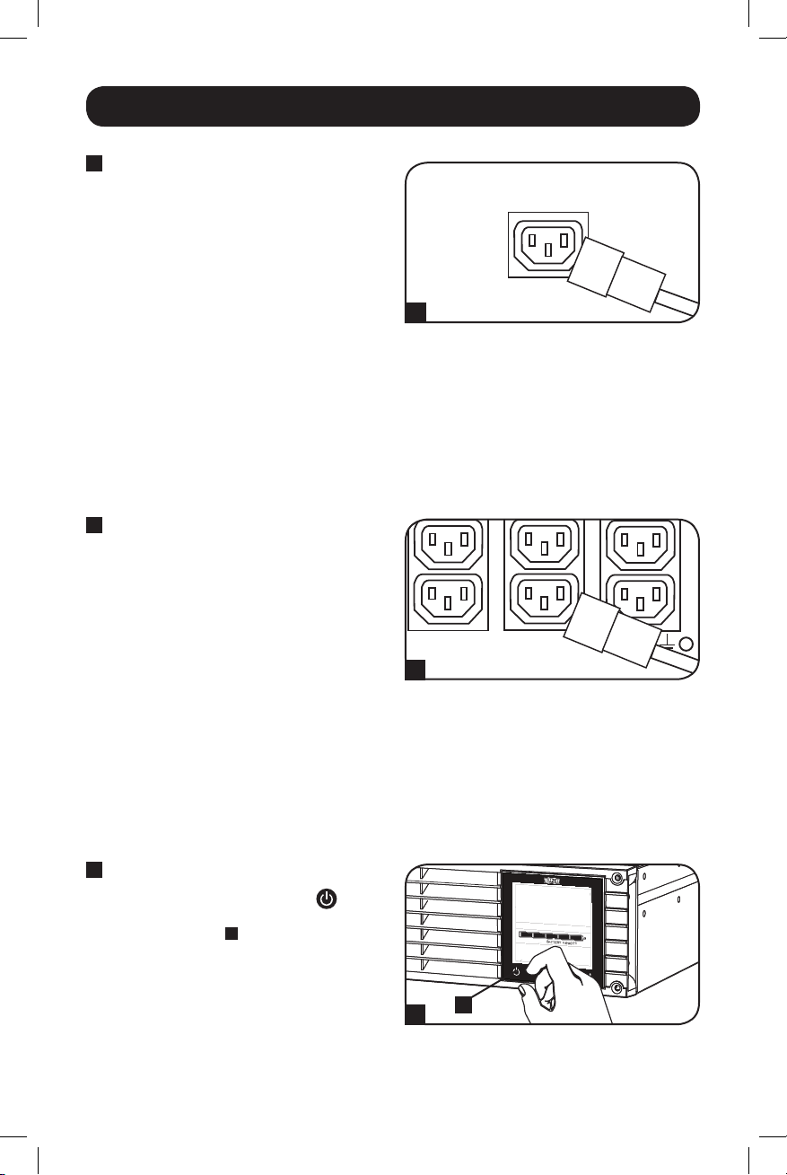
1
Insert a user-supplied power
cord (with country-specific
plug) into the UPS Systems
IEC inlet connection. Plug the
other end into your countryspecific wall outlet.*
NOTE! After you plug the UPS into a live
AC outlet, the UPS (in “Standby Mode”)
will automatically charge its batteries,
but will not supply power to its outlets
until it is turned ON.
* See the UPS systems nameplate for input
requirements. Additional input cords are also
available from Tripp Lite.
2
Plug your equipment into
the UPS.*
Additional C13-to-C14 interconnection
cord(s) are included to connect your
equipment to the UPS.
NOTE: Additional interconnection cords are
available from Tripp Lite.
* Your UPS is designed to support only electronic
equipment. You will overload the UPS if the total
VA ratings for all the equipment you connect
exceeds the UPS’s Output Capacity. To find your
equipment’s VA ratings, look on their
nameplates. If the equipment is listed in amps,
multiply the number of amps by 230 to
determine VA. (Example: 1 amp × 230 = 230
VA). If you are unsure if you have overloaded
the UPS’s outlets, see LOAD icon description in
LCD Interface section under Basic Operation.
1
2
3
Turn the UPS ON.
Press and hold the
second. The alarm will beep once briefly.
Note: UPS system will function properly upon
initial startup, however, maximum runtime and a
successful self-test will only be accessible after it
has been charged for 24 hours.
18-09-245-933184.indb 6 12/21/2018 11:07:23 AM
button A for one
A
3
6
Page 7
4-5
Optional Installation
These connections are optional. Your UPS will function properly without these connections.
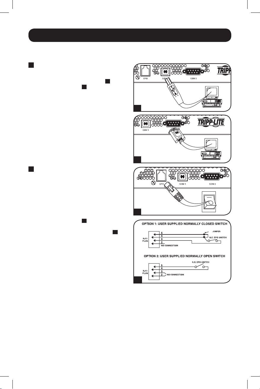
1
USB and RS-232 Serial
Communications
Use the included USB cable (see 1A) or
DB9 serial cable (see 1B) to connect the
communication port on your computer to
the communication port of your UPS. Install
on your computer the Tripp Lite PowerAlert
Software appropriate to your computer’s
operating system.
2
EPO Port Connection
This optional feature is only for those
applications which require connection to a
facility’s Emergency Power Off (EPO) circuit.
When the UPS is connected to this circuit, it
enables emergency shutdown of the UPS’s
inverter.
Using the cable provided, connect the EPO
port of your UPS (see
normally closed or normally open switch
according to the circuit diagram (see 2B).
The EPO port is not a phone line surge
suppressor; do not connect a phone line to
this port.
2A
) to a user-supplied
1A
1B
2A
2B
7
18-09-245-933184.indb 7 12/21/2018 11:07:24 AM
Page 8
Optional Installation continued
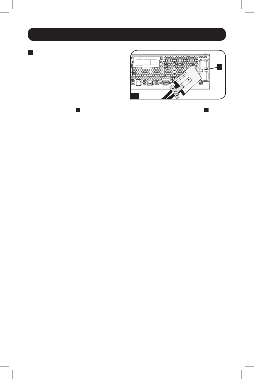
3
External Battery Connection
(Select Models)
Your UPS comes with a robust internal
battery system; external batteries are
needed only to extend runtime. Adding
external batteries will increase recharge
time as well as runtime. Contact Tripp Lite
to find out which external battery packs
your model supports.
3
The illustration (see
) shows the location of your UPS’s External Battery Connector A where
you will insert the battery pack cable. Complete installation instructions for your battery pack
appear in the battery pack owner’s manual. Make sure that cables are fully inserted into their
connectors. Small sparks may result during battery connection; this is normal.
Do not connect or disconnect battery packs when the UPS is running on battery power.
Caution! When an external battery pack is connected, make sure the AC load does not
exceed the nameplate rating. Select models are derated when an external battery pack
is connected. See UPS nameplate label for derating details.
When connecting external batteries to the UPS, go to the Tripp Lite website at
www.tripplite.com/en/support/bpconfig/index.cfm to download the External Battery Pack Utility
software to configure your UPS for external battery support.
Note:
1. The runtime and charge rate will automatically recalculate once the External Battery Pack Tool process is
complete.
2. If the setup will no longer include external batteries, the UPS can be configured to work without external
batteries via the LCD Screen. See External Battery Settings Control section under Basic Operation for
details.
3. If external battery packs are removed, the UPS must be reset to “NO EXTERNAL BATTERY” via the LCD
interface or the External Battery Configuration Program available on the Tripp Lite website. Failure to do
so may result in damage to the internal batteries due to over-charging.
3
A
8
18-09-245-933184.indb 8 12/21/2018 11:07:26 AM
Page 9
Basic Operation
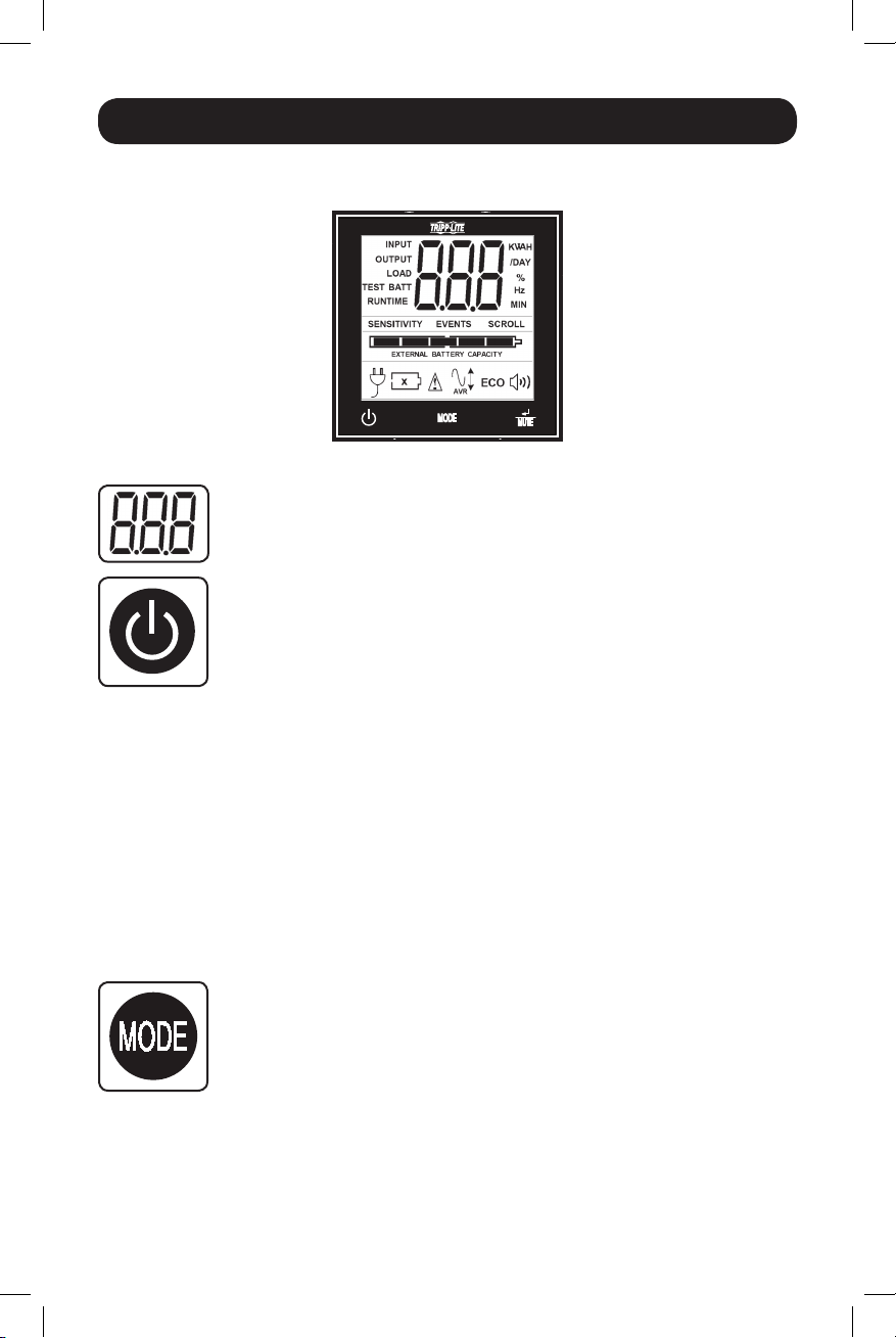
LCD Interface
3-Digit Display: This display is generally used to show values for a given
“Display” or “Control” screen.
“ON/OFF” Button
• To turn the UPS ON: After you plug the UPS into a live AC outlet, the UPS (in
”Standby” mode) will automatically charge its batteries, but will not supply
power to its outlets until it is turned ON. With the UPS plugged into a live AC
wall outlet, press and hold the “ON/OFF” button for one second.* The UPS
will beep once to indicate ON status. Release the button.
• To cold-start the UPS: If utility power is absent, you can “cold-start” the UPS
(i.e.: turn it ON and supply power for a limited time from its batteries) by
pressing and holding the “ON/OFF” button for one second.* The UPS will beep
once to indicate ON status. Release the button.
• To turn the UPS OFF: With the UPS ON and receiving utility power, press and
hold the “ON/OFF” button for 2.5 seconds.* The UPS will beep once to
indicate OFF status. Then unplug the UPS from the wall outlet. The UPS will
be completely OFF.
* If the user unintentionally presses the ON/OFF button, the OFF function can be
temporarily canceled by continuing to hold the ON/OFF button until the UPS beeps and
then momentarily pressing either the MODE button or the ENTER/MUTE button. Once
both buttons are released, the UPS will remain ON.
Note: This LCD image is shown
with all icons illuminated. Under
normal conditions, only select
icons will be lit.
“MODE” Button
To enable viewing of power displays and control menu options, tap this button.
See “Display Power Conditions” & “Control Menu Options” for details.
• Can be used in conjunction with the ON/OFF button to cancel the “OFF”
function. See “ON/OFF Button” instructions above.
• Can be used in conjunction with the ENTER/MUTE button to restore the LCD
to Factory Mode. See “Control Menu Options”.
9
18-09-245-933184.indb 9 12/21/2018 11:07:26 AM
Page 10
Basic Operation continued
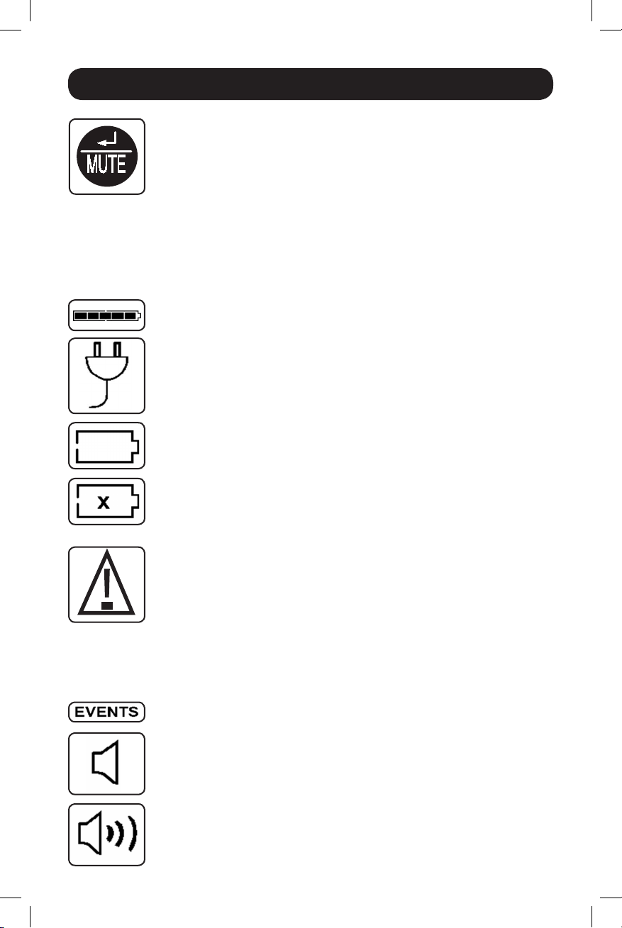
“ENTER/MUTE” Button
To toggle settings options while viewing a control menu option, tap this button.
The UPS power failure alarm can also be temporarily silenced by tapping this
button. Once silenced, an alarm will automatically re-sound to indicate low
battery conditions and can no longer be silenced.
• Can be used in conjunction with the ON/OFF button to cancel the “OFF”
function. See “ON/OFF Button” instructions above.
• Can be used in conjunction with the ENTER/MUTE button to restore the LCD
to Factory Mode. See “ON/OFF Button” instructions.
Note: Alarm-free silent operation is available by setting the alarm to disable
(see CONTROL MENU OPTIONS / ALARM ENABLE-DISABLE section).
Battery Capacity: This will be active in all “Display” modes, but is not shown
in “Control” modes.
AC Input: This indicates that the unit is running in Line Mode and supplying AC
power to equipment connected to the output.
Battery Input: This will flash to indicate that the UPS is not receiving AC input
and is running in inverter mode. The Battery Input icon is also used in
conjunction with the EVENTS icon to indicate On Battery events.
Replace Battery Icon: In the event that UPS batteries expire and require
replacement, this icon and the warning icon will flash. This icon will also flash
after a failed UPS self-test (see the BASIC OPERATION / CONTROL MENU
OPTIONS / SELF-TEST section for more information).
Warning: This will flash to let the user know that there’s a warning condition
and immediate action must be taken:
1. For Replace Battery: Replace Battery and Warning icons flash during any
normal “Display” mode.
2. For Overload: Load, Warning and Load Percentage icons will flash, the alarm
will sound repeatedly and the LCD screen will switch from the user-selected
display mode to Load Percentage. Overload indication is available in both AC
and battery modes. CAUTION! Any overload condition that is not corrected by
the user immediately may cause the UPS to shut down and cease supplying
power in the event of a blackout or brownout.
EVENTS Icon: Displayed in conjunction with the AVR icon and BATT icons to
indicate the number of On Battery or AVR events that have occurred.
Alarm Off: Indicates that the alarm is disabled.
Alarm On: Indicates that the alarm is enabled.
10
18-09-245-933184.indb 10 12/21/2018 11:07:27 AM
Page 11
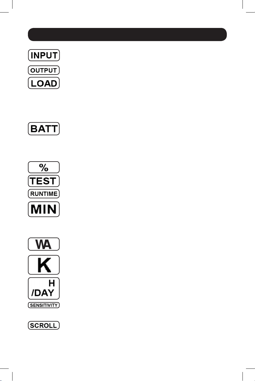
Basic Operation continued
INPUT Icon: Indicates that the 3-digit value displayed is the Input Voltage.
OUTPUT Icon: Indicates that the 3-digit value displayed is the Output Voltage.
LOAD Icon: Displayed in two modes:
1. Displayed in conjunction with the % icon and 3-digit value to indicate the
load percentage.
2. Displayed in conjunction with KWH/Day and 3-digit value to indicate daily
power consumption.
3. Both the LOAD icon and Warning icon will flash to indicate an overload.
BATT Icon: Displayed in two modes:
1. BATT icon (displayed in conjunction with % icon and 3-digit value) indicates
the Battery Capacity %.
2. BATT icon is shown with TEST icon to indicate self-test mode or control
mode.
% Icon: Indicates units of %.
TEST Icon: Displayed in conjunction with BATT icon to indicate that the UPS is
performing a self-test.
RUNTIME Icon: Displayed in conjunction with the MIN icon and 3-digit value to
indicate Runtime in minutes.
MIN Icon: Indicates units of minutes.
1. Displayed in conjunction with RUNTIME icon and 3-digit value to indicate
battery runtime in minutes.
2. Displayed in conjunction with the 3-digit value (reporting “LCD”) to indicate
the minimum brightness.
VWA Icon: This is a multipurpose icon which indicates units of Volts, VA, Watts,
or Amps (V, VA, W, or A will be shown).
K Icon: Displayed in conjunction with the W to indicate Kilowatts. It is also
used in conjunction with the WH and /DAY icons to indicate Kilowatt Hours per
Day.
H and /DAY Icons: Displayed in conjunction with “K” and “W” icons to indicate
Kilowatt Hours per day (KWH/DAY).
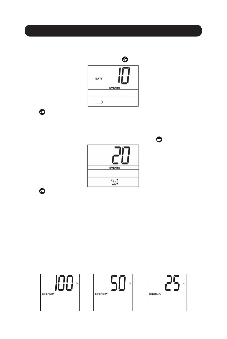
Sensitivity Icon: Displayed to set the AC input line sensitivity setting.
Sensitivity settings available are 100% (Normal = Full Counter clockwise POT),
50% (half delay), and 25% (full delay = full Clockwise POT).
SCROLL Icon: When enabled, the display will automatically cycle through each
DISPLAY mode of the LCD once per two-second interval. If a button is pressed
while Scroll Mode is enabled, the scroll function will pause for 10 seconds to
allow the user to manually make menu selections before resuming scroll.
11
18-09-245-933184.indb 11 12/21/2018 11:07:27 AM
Page 12
Basic Operation continued
Automatic Voltage Regulation Icon: Indicates that the AC input is either low
or high and that the AVR function is actively boosting or cutting the line. The
AVR icon is also used in conjunction with the EVENTS icon to indicate AVR
events.
EXTERNAL BATTERY Icon (Select Models): Displayed only when the EXTERNAL
BATTERY SETTING CONTROL is active.
BATTERY CAPACITY Icon: Used to better describe the battery capacity bar
graph.
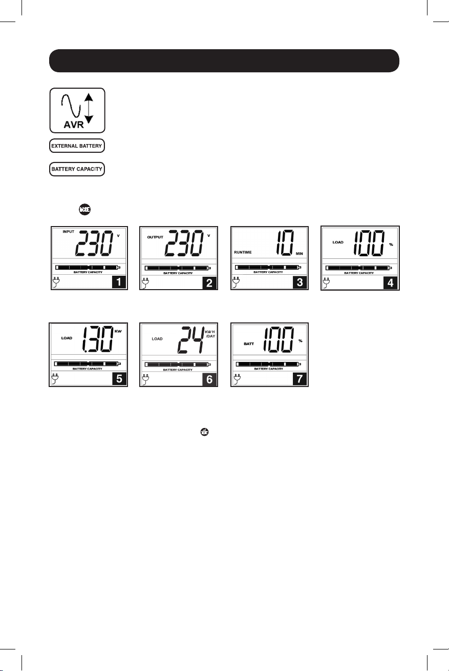
Display Power Conditions
Use the
button to advance through power conditions.
1. Voltage In 2. Voltage Out 3. Estimated Runtime
4. Load %
(in minutes)
5. Load Wattage* 6. KWH/Day** 7. Battery Capacity %
* Load Wattage is displayed in watts up to “999”, and then will be displayed in Kilowatts.
** The Kilowatt Hour usage per day reports daily power consumption of equipment connected to the UPS in
KWH in a 24-hour cycle. Press and hold the
Note: When the UPS is in Battery Mode (power is supplied to the output from the batteries), the BATTERY icon
will be lit in the display instead of the AC INPUT icon.
button for 4 seconds to reset the accumulator to “0”.
12
18-09-245-933184.indb 12 12/21/2018 11:07:28 AM
Page 13
Basic Operation continued
Control Menu Options
Enable/Disable Alarm
Tap the
button to select ON or OFF alarm mode settings. The last option displayed before navigating away
from this menu option will be the selected setting.
Note: Disabling the alarm via this control menu option will silence the alarm under all conditions, including low
battery conditions.
LCD Brightness
Tap the
displayed before navigating away from this menu option will be the selected setting.
Note: The default brightness is set at medium. Any time a button is pressed, the LCD will engage the high
brightness setting. After 2 minutes of inactivity, the backlight will revert to the selected setting until a button is
pressed.
Self-test
Tap the
the test. The test will last approximately 10 seconds as the UPS switches to battery to test the
capacity with a load. Upon completion of the test, the display will indicate PAS or BAD (pass or
bad) for 20 seconds, and then return to the home screen. Connected equipment can remain on
during the test. Do not unplug your UPS to test it; this will remove safe electrical grounding.
Note: If the self-test result is BAD, it may be due to the batteries not being charged for 24 hours. Fully charge
the batteries and repeat the self-test. Please refer to the note under Step 3 on page 6.
A Replace Battery Condition will result in the Replace Battery and Warning icons flashing every
second and the audible alarm sounding repeatedly.
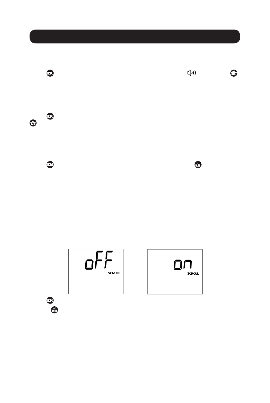
Scroll Control
This display option allows the user to select the option to automatically scroll each operating
condition of the UPS (such as Input Voltage, Output Voltage and Runtime) automatically.
button repeatedly to advance to the LCD display featuring the icon. Press the
button repeatedly to advance to the LCD Brightness display marked “LCD”. Press the
button to select Medium Backlight (default), High Backlight or Dim Backlight. The last option
button repeatedly to advance to the TEST BATT display. Press the button to initiate
Tap the
Press the
navigating away from this menu option, will be the selected setting.
Note:
1. Each condition is displayed in 2 second intervals.
2. If a button is pressed while Scroll Mode is enabled, the scroll function will pause for 10 seconds to allow the
user to manually make menu selections.
18-09-245-933184.indb 13 12/21/2018 11:07:28 AM
button repeatedly to advance to the Scroll display as shown above.
button to advance to the next available option. The last option displayed, before
13
Page 14
Basic Operation continued
ON Battery Events
This feature allows the user to view the number of times the UPS has experienced an ON Battery
Event. To reset the counter to “0”, press and hold the button.
Tap the button repeatedly to advance to the ON Battery Events display, as shown above.
Note: The value displayed is a random value used for example reference.
AVR Events
This feature allows the user to view the number of times the UPS has experienced an Automatic
Voltage Regulation Event. To reset the counter to “0”, press and hold the
button.
Tap the
Note: The value displayed is a random value used for example reference.
button repeatedly to advance to the AVR display, as shown above.
Power Sensitivity
This setting is normally set to 100%, which enables the UPS to protect against waveform
distortions in its AC input. When such distortion occurs, the UPS will normally switch to providing
pure sine wave power from its battery reserves for as long as the distortion is present. In some
areas with poor utility power or where the UPS’s input power comes from a backup generator,
frequent brownouts and/or chronic waveform distortion could cause the UPS to switch to battery
too often, draining its battery reserves. You may be able to reduce how often your UPS switches to
battery due to waveform distortion or brownouts by experimenting with different settings. As the
setting is reduced, the UPS becomes more tolerant of variations in its input power’s AC waveform.
Note: When experimenting with different settings, operate connected equipment in a safe test mode so that the
effect on the equipment of any waveform distortions in the UPS’s output can be evaluated without disrupting
critical operations. The experiment should last long enough to assure that all expected line conditions are
encountered.
14
18-09-245-933184.indb 14 12/21/2018 11:07:29 AM
Page 15
Basic Operation continued
Tap the button repeatedly to advance to Sensitivity display, as shown on the previous page.
Press the
away from this menu option, will be the selected setting.
button to advance through the options. The last option displayed, before navigating
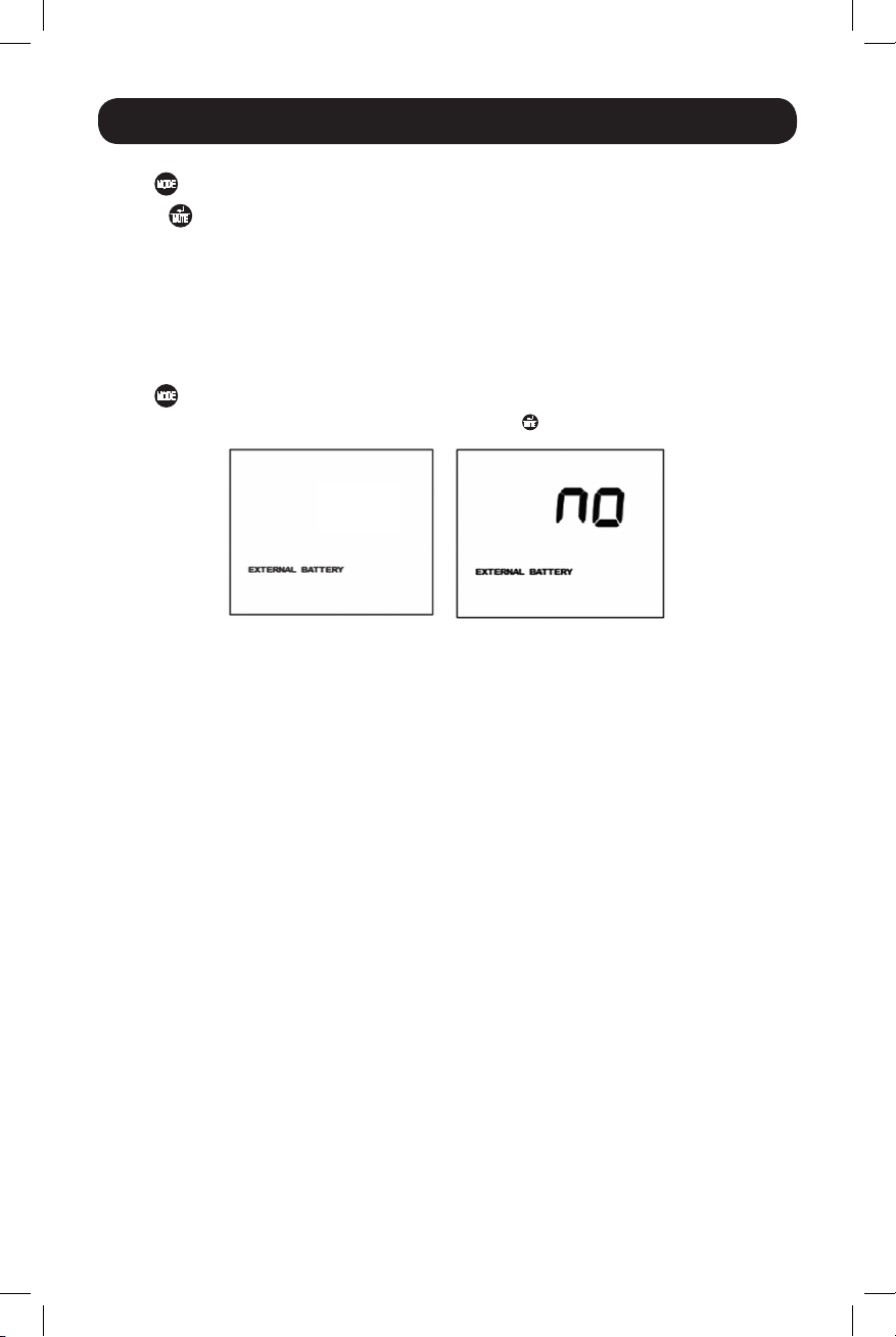
External Battery Setting Control (Select Models)
This control menu option only appears when the UPS is configured using the External Battery Utility
software and is reporting “YES” in the External Battery LCD Control Screen. The only available LCD
interface configuration option is to change the setting from “YES” to “NO” external batteries.
Note: See the Optional Installation section for information on configuring the UPS for external battery operation
using the External Battery Utility software.
Tap the
To set the UPS to “NO” External Battery, press and hold the button for 3.5 seconds.
button repeatedly to advance to the External Battery display, as shown below.
YES
Note: The Battery Runtime calculation is based on this setting. The runtime and charger rate will automatically
recalculate once the external battery setting is configured for “NO” external batteries.
Factory Mode Reset
The LCD settings can be restored to Factory Mode by holding the MODE and ENTER/MUTE buttons
simultaneously for 5 seconds while in any display mode.
CAUTION: This action cannot be undone. The user must reconfigure the UPS for external
batteries if the UPS’s setup includes external batteries.
15
18-09-245-933184.indb 15 12/21/2018 11:07:29 AM
Page 16
Basic Operation continued
Other UPS Features (Rear Panel)
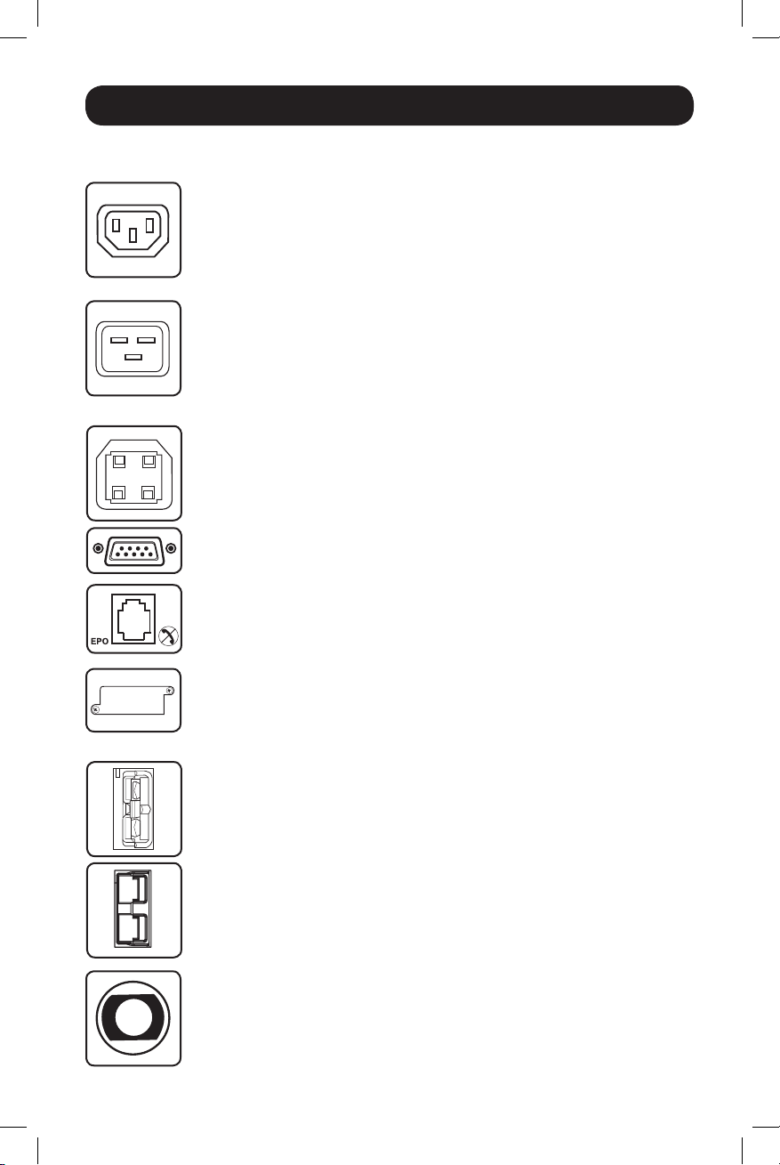
AC Outlets: All models include IEC 320-C13 outlets. Select models also
include IEC 320-C19 outlets. These outlets provide your connected equipment
with AC line power during normal operation and battery power during blackouts
and brownouts. The UPS protects equipment connected to these outlets against
damaging surges and line noise. If you have a serial or USB connection to your
IEC 320-C13
IEC 320-C19
UPS, you can remotely reboot connected equipment by turning the outlets OFF
and ON using Tripp Lite’s PowerAlert Software. The outlets are divided into one
or more load banks (labelled “LOAD 1,” etc.) which may be remotely switched
OFF and ON without interrupting power to equipment connected to the other
outlets. Outlets labelled “UNSWITCHED” may not be remotely switched off.
Communications Ports (USB or RS-232): These ports connect your UPS to
any workstation or server. Use with Tripp Lite’s PowerAlert Software and included
cables to enable your computer to automatically save open files and shut down
equipment during a blackout. Also use PowerAlert Software to monitor a wide
variety of AC line power and UPS operating conditions. Consult your PowerAlert
Software manual or contact Tripp Lite Customer Support for more information.
See “USB and RS-232 Serial Communications” in the “Optional Installation”
section for installation instructions.
EPO (Emergency Power Off) Port: Your UPS features a EPO port that may be
used to connect the UPS to a contact closure switch to enable emergency
inverter shutdown. See Optional Installation.
Accessory Slot: Remove the small cover panel from this slot to install optional
accessories to remotely monitor and control your UPS. Refer to your accessory’s
manual for installation instructions. Contact Tripp Lite Customer Support at www.
tripplite.com/support for more information, including a list of available SNMP,
network management and connectivity products.
External Battery Connector (optional on select models): Use to connect
Tripp Lite external battery packs for additional runtime. Refer to instructions
available with the battery pack for complete connection information and safety
warnings. Visit www.tripplite.com/support/battery/index.cfm to locate the
supported battery type(s) for your UPS.
Output Breaker (select models): Your UPS features one or more breakers that
protect your UPS from output overload. If one or more breakers trip, remove
some of the load on the circuit(s), then reset them by pressing the breaker
switch(es) in.
16
18-09-245-933184.indb 16 12/21/2018 11:07:30 AM
Page 17

Basic Operation continued
Ground Screw: Use this to connect any equipment that requires a chassis
ground.
Storage and Service
Storage
Before storing your UPS, turn it completely OFF: with the UPS ON and receiving utility power, press
and hold the “ON/OFF” button for two seconds (an alarm will beep once briefly after the interval
has passed); then, unplug the UPS from the wall outlet. If you store your UPS for an extended
period of time, recharge the UPS batteries once every three months: plug the UPS into a wall
outlet; allow it to charge for 12 hours; and then unplug it and place it back in storage. If you leave
your UPS batteries discharged for an extended period of time, they will suffer a permanent loss of
capacity.
Service
A variety of Extended Warranty and On-Site Service Programs are also available from Tripp Lite. For
more information on service, visit www.tripplite.com/support. Before returning your product for
service, follow these steps:
1. Review the installation and operation procedures in this manual to insure that the service
problem does not originate from a misreading of the instructions.
2. If the problem continues, do not contact or return the product to the dealer. Instead, visit www.
tripplite.com/support.
3. If the problem requires service, visit www.tripplite.com/support and click the Product Returns
link. From here you can request a Returned Material Authorization (RMA) number, which is
required for service. This simple on-line form will ask for your unit’s model and serial numbers,
along with other general purchaser information. The RMA number, along with shipping
instructions will be emailed to you. Any damages (direct, indirect, special or consequential) to
the product incurred during shipment to Tripp Lite or an authorized Tripp Lite service center is
not covered under warranty. Products shipped to Tripp Lite or an authorized Tripp Lite service
center must have transportation charges prepaid. Mark the RMA number on the outside of the
package. If the product is within its warranty period, enclose a copy of your sales receipt.
Return the product for service using an insured carrier to the address given to you when you
request the RMA.
17
18-09-245-933184.indb 17 12/21/2018 11:07:30 AM
Page 18
Battery Replacement
Under normal conditions, the original batteries in your UPS will last many years. See Safety section
before replacing batteries. The batteries are designed for hot-swap replacement (i.e., leaving the
UPS in ON mode), but some qualified service personnel may wish to put the UPS in the OFF mode
and disconnect equipment before proceeding.
Note: Refer to the label on the battery retention plate for the R.B.C. part number.
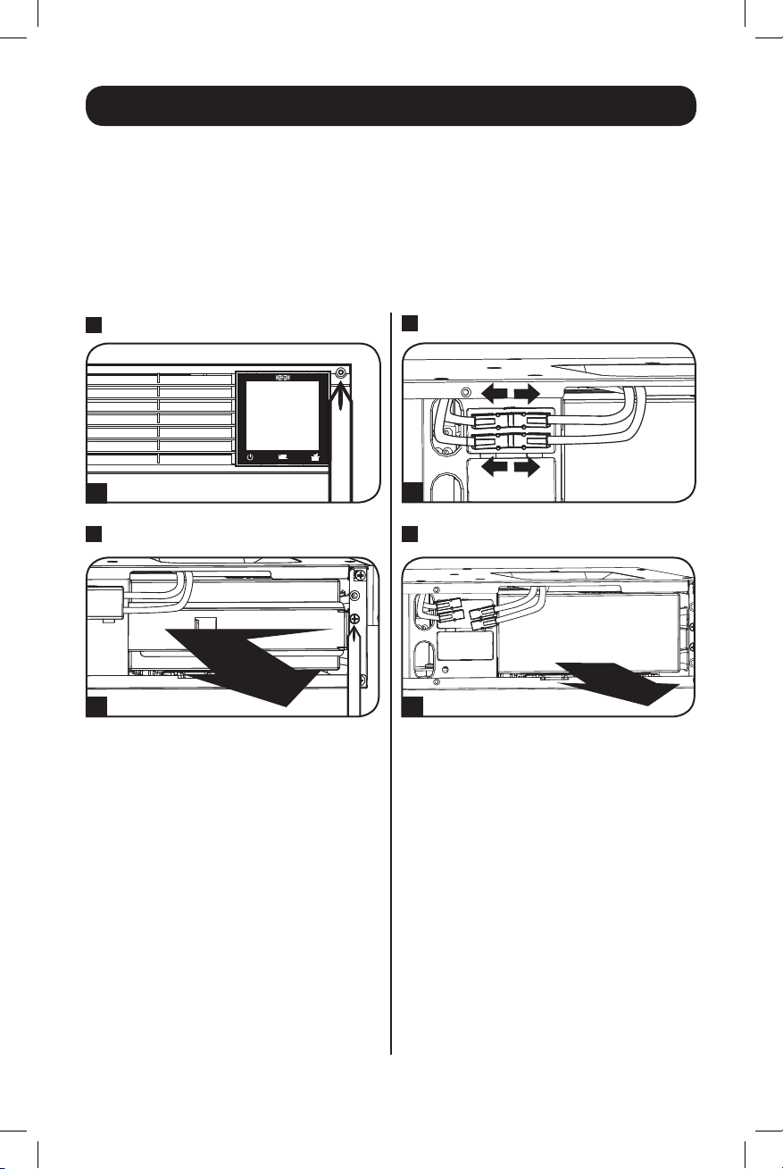
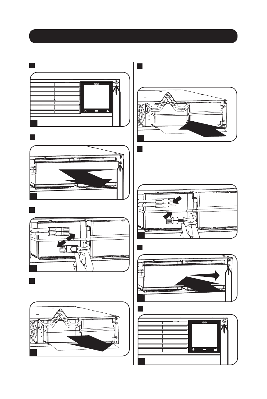
SMX1000RT2U Battery Replacement Procedure
1
Remove Front Panel
4 x screws
1
2
Remove Battery Retention Plate
4 x screws
2
3
Disconnect Batteries
3
4
Remove/Recycle Batteries
4
18
18-09-245-933184.indb 18 12/21/2018 11:07:32 AM
Page 19
Battery Replacement
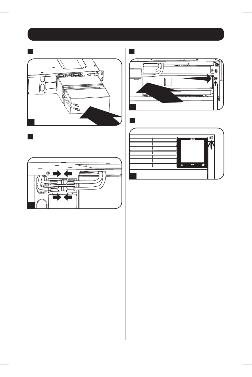
5
Add New Batteries
5
6
Connect Batteries
Always ensure that the battery
terminals are properly secured.
6
7
Replace Battery Retention Plate
4 x screws
7
8
Replace Front Panel
4 x screws
8
19
18-09-245-933184.indb 19 12/21/2018 11:07:33 AM
Page 20
Battery Replacement
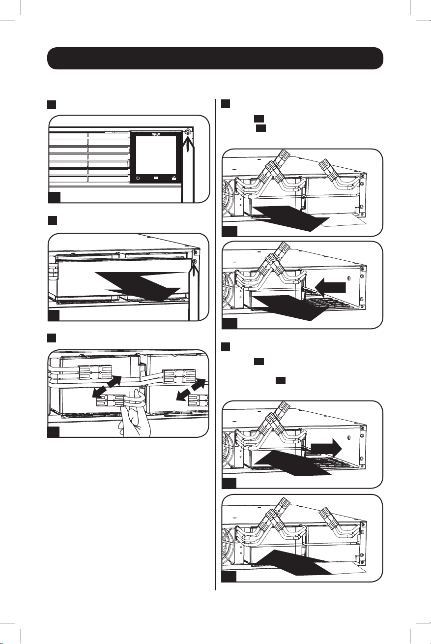
SMX1500RT2U Battery Replacement Procedure
1
Remove Front Panel
4 x screws
1
2
Remove Battery Retention Plate
6 x screws
2
3
Disconnect Batteries
5
Add New Batteries
First, install the row of batteries by inserting
them, pressing forward and snapping them in.
5
6
Connect Batteries
Attach both sets of connectors as shown:
black-to-black and red-to-red.
Always ensure that the battery
terminals are properly secured.
6
7
Replace Battery Retention Plate
3
4
Remove/Recycle Batteries
6 x screws
7
8
Replace Front Panel
4
4 x screws
8
20
18-09-245-933184.indb 20 12/21/2018 11:07:36 AM
Page 21
Battery Replacement
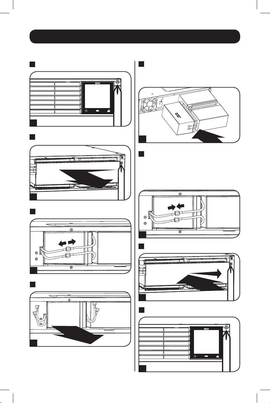
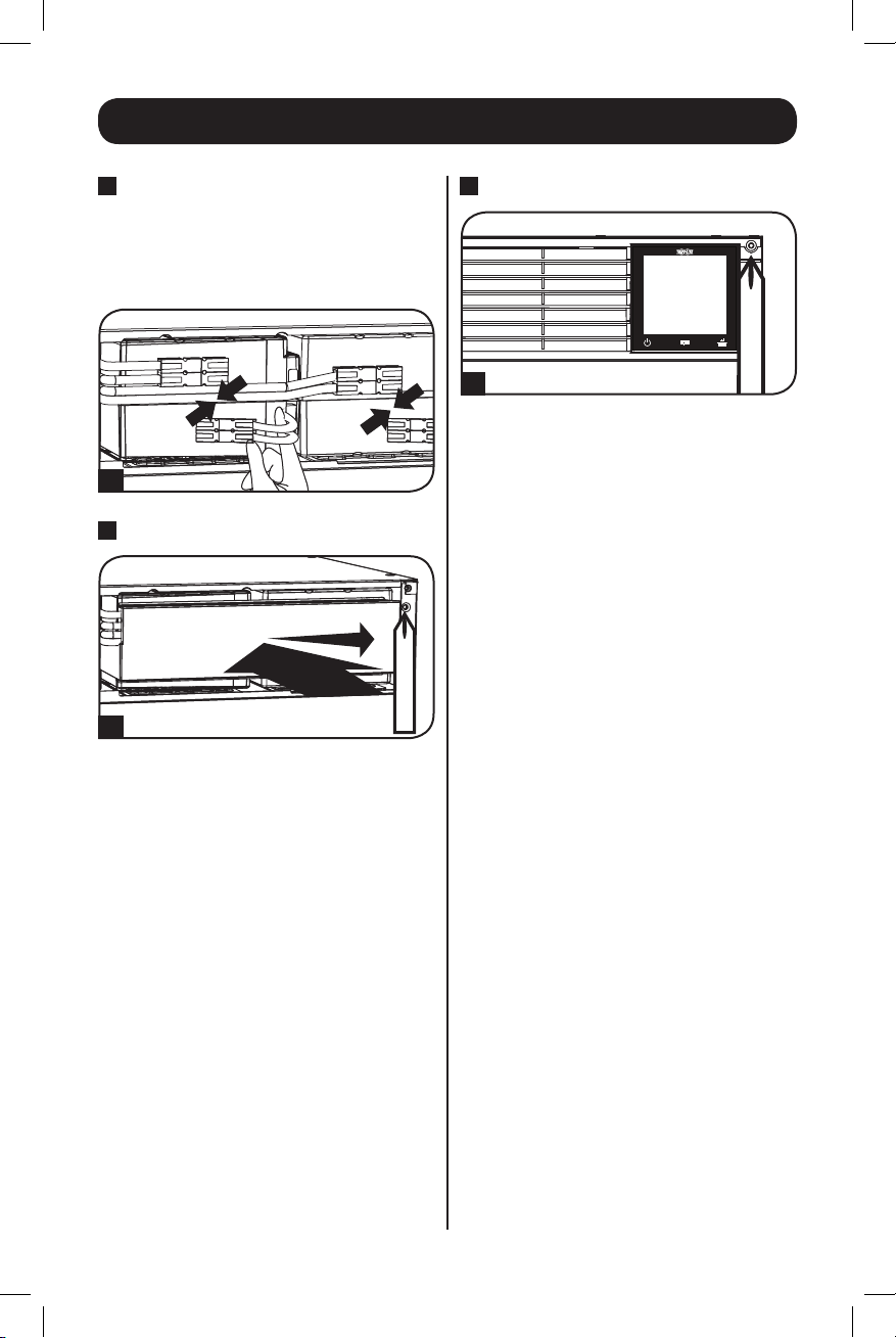
SMX2200XLRT2U Battery Replacement Procedure
1
Remove Front Panel
4 x screws
1
2
Remove Battery Retention Plate
4 x screws
2
3
Disconnect Batteries
5
Add New Batteries
Install the replacement batteries by sliding
them directly into the UPS cabinet.
5
6
Connect Batteries
Attach both sets of connectors as shown:
black-to-black and red-to-red.
Always ensure that the battery
terminals are properly secured.
6
7
Replace Battery Retention Plate
3
4
Remove/Recycle Batteries
Remove batteries by sliding them directly
out of the UPS cabinet.
4 x screws
7
8
Replace Front Panel
4
4 x screws
8
21
18-09-245-933184.indb 21 12/21/2018 11:07:38 AM
Page 22
Battery Replacement
SMX3000XLRT2UA Battery Replacement Procedure
1
Remove Front Panel
4 x screws
1
2
Remove Battery Retention Plate
4 x screws
2
3
Disconnect Batteries
4
Remove/Recycle Batteries
First, 4A remove the left row of batteries.
Then, 4B slide the right row of batteries to
the left and remove.
4A
4B
5
Add New Batteries
First, 5A install the right row of batteries by
inserting them and sliding them to the
right. Then, 5B install the left row of
batteries.
3
5A
5B
22
18-09-245-933184.indb 22 12/21/2018 11:07:41 AM
Page 23
Battery Replacement
6
Connect Batteries
Attach both sets of connectors as shown:
black-to-black and red-to-red.
Always ensure that the battery
terminals are properly secured.
6
7
Replace Battery Retention Plate
4 x screws
7
8
Replace Front Panel
4 x screws
8
23
18-09-245-933184.indb 23 12/21/2018 11:07:42 AM
Page 24
Warranty Registration
Visit www.tripplite.com/warranty today to register the warranty for your new Tripp Lite product. You’ll
be automatically entered into a drawing for a chance to win a FREE Tripp Lite product!*
* No purchase necessary. Void where prohibited. Some restrictions apply. See website for details.
Regulatory Compliance Identification Numbers
For the purpose of regulatory compliance certifications and
identification, your Tripp Lite product has been assigned a
unique series number. The series number can be found on
the product nameplate label, along with all required approval
markings and information. When requesting compliance
information for this product, always refer to the series
number. The series number should not be confused with the
marking name or model number of the product.
WEEE Compliance Information for Tripp Lite Customers and Recyclers (European Union)
Under the Waste Electrical and Electronic Equipment (WEEE) Directive and implementing
regulations, when customers buy new electrical and electronic equipment from Tripp Lite they are
entitled to:
• Send old equipment for recycling on a one-for-one, like-for-like basis (this varies depending on
the country)
• Send the new equipment back for recycling when this ultimately becomes waste
Tripp Lite has a policy of continuous improvement. Product specifications are subject to change without notice.
Note on Labeling
Two symbols are used on the label.
V~ : AC Voltage
: DC Voltage
V
1111 W. 35th Street, Chicago, IL 60609 USA • www.tripplite.com/support
24
18-09-245-933184.indb 24 12/21/2018 11:07:42 AM
Page 25

Manual del Propietario
SmartPro® para Instalación 2U en Rack
Sistemas UPS Inteligentes, Interactivos
Salida de Onda Sinusoidal de 230V• Capacidades 1000VA—3000VA
SMX1000RT2U
(Número de Serie: AG-0072)
SMX1500XLRT2U
(Número de Serie: AG-0071)
No adecuado para aplicaciones móviles.
SMX2200XLRT2U
(Número de Serie: AG-0070)
SMX3000XLRT2UA
(Número de Serie: AG-0069)
Instrucciones de Seguridad Importantes 26
Instalación 28
Instalación Rápida 30
Instalación Opcional 31
Operación Básica 33
Almacenamiento y Servicio 41
Reemplazo de las Baterías 42
Avisos 48
English 1
Français 49
Русский 73
Deutsch 97
1111 W. 35th Street, Chicago, IL 60609 USA • www.tripplite.com/support
Copyright © 2018 Tripp Lite. Todos los derechos reservados. SmartPro® es una marca registrada de Tripp Lite.
25
18-09-245-933184.indb 25 12/21/2018 11:07:42 AM
Page 26

Instrucciones de Seguridad Importantes
GUARDE ESTAS INSTRUCCIONES
Este manual contiene instrucciones importantes que deberán seguirse durante la instalación, el
funcionamiento y el almacenamiento de este producto. No adehrirse a estas advertencias puede
anular su garantía.
Advertencias para la Ubicación del UPS
• Tenga cuidado cuando levante el UPS. Debido al peso considerable de todos los sistema UPS
para instalación en rack, deben ayudar al menos dos personal al levantarlos e instalarlos.
• Instale el UPS en interiores, alejado del exceso de humedad o calor, el polvo o la luz solar directa.
• Para obtener un mejor rendimiento, la temperatura ambiente cerca del UPS debe oscilar entre
los 0° C y los 40° C (entre 32° F y 104° F).
• Deje espacio suficiente alrededor del sistema UPS para una ventilación adecuada. No obstruya
las ventilaciones o las aberturas del ventilador.
• Al instalar el sistema de UPS en posición de torre, asegúrese de que la pantalla LCD esté en la
parte superior del UPS, no en la inferior.
• No instale la unidad con el panel frontal o trasero orientado hacia abajo (en cualquier ángulo). Si
la instala de esta manera inhibirá gravemente la capacidad de enfriamiento interno de la unidad,
lo que eventualmente provocará daños en el producto no cubiertos por la garantía.
Advertencias para la Conexión del UPS
• El UPS contiene su propia fuente de energía (batería). Las terminales de salida pueden tener
corriente aún cuando el sistema de UPS no esté conectado a una fuente de CA.
• Conecte el UPS a un tomacorriente CA adecuadamente conectado a tierra. No modifique
el enchufe del UPS de alguna forma que elimine la conexión a tierra del UPS. No utilice
adaptadores que eliminen la conexión a tierra del UPS.
• El tomacorriente que alimenta al UPS debe estar instalado cerca del UPS y ser fácilmente
accesible.
• No enchufe el UPS a sí mismo, lo dañará y anulará la garantía.
• Si conecta el UPS a un generador de CA accionado por motor, el generador debe proporcionar
salida filtrada y regulada de grado de computadora. Si conecta el UPS a un generador se anulará
el Seguro máximo de por vida.
Advertencias sobre la conexión de equipos
• No se recomienda usar este equipo en aplicaciones de mantenimiento artificial de vida, donde se
puede esperar razonablemente que su falla cause la falla del equipo de mantenimiento de vida o
que afecte de manera importante su seguridad o eficiencia. No use este equipo en presencia de
mezclas anestésicas inflamables con aire, oxígeno u óxido nitroso.
• No conecte supresores de sobretensiones o cables de extensión al tomacorriente del UPS. Esto
puede dañar el UPS y puede afectar las garantías del supresor de sobretensiones y del UPS.
26
18-09-245-933184.indb 26 12/21/2018 11:07:42 AM
Page 27

Instrucciones de Seguridad Importantes
Advertencias sobre las baterías
• Las baterías pueden presentar el riesgo de descargas eléctricas y de causar quemaduras por
cortocircuitos de alta tensión. Tome las precauciones necesarias. No deseche las baterías
en el fuego. No abra el UPS ni las baterías. No haga cortocircuito ni puente en los terminales
de la batería con ningún objeto. Antes de cambiar la batería, desenchufe y apague el UPS.
Utilice herramientas con mangos aislados. Dentro del UPS no hay partes que el usuario pueda
reparar. El reemplazo de baterías debe hacerlo sólo el personal de servicio autorizado utilizando
el mismo número y tipo de baterías (ácido-plomo selladas). Las baterías se pueden reciclar.
Consulte las normas locales para obtener los requisitos de desecho o visite www.tripplite.com/
UPSbatteryrecycling para ver la información de reciclado. Tripp Lite ofrece una línea completa de
Cartuchos de baterías de reemplazo (R.B.C.) para sistemas UPS. Visite Tripp Lite en la Web en
www.tripplite.com/support/battery/index.cfm para buscar la batería de reemplazo específica para
su UPS. El tipo RBC también puede encontrarse en la etiqueta fina en la placa de sujeción de la
batería.
• Cuando reemplaza la batería mientras el UPS está encendido, éste no podrá proporcionar
respaldo de energía en el caso de un apagón u otras interrupciones eléctricas.
• No utilice el UPS sin baterías.
Advertencias para la Conexión de la Batería Externa
• Cuando agregue módulos de baterías externos en modelos selectos con conectores para
módulos de baterías externos, conecte únicamente módulos de baterías recomendados por Tripp
Lite del tipo y tensión correctos. No conecte o desconecte módulos de baterías cuando el UPS
está funcionando con energía de la batería. Visite www.tripplite.com/support/battery/index.cfm
para localizar los tipos de baterías admitidos por su UPS.
27
18-09-245-933184.indb 27 12/21/2018 11:07:42 AM
Page 28
Instalación (Rack)
Instale el equipo en un rack o gabinete de rack de 2 ó 4 postes. El usuario debe determinar la
idoneidad de las herramientas y los pasos antes de montarlo. Si las herramientas o los
procedimientos no son adecuados para la aplicación, comuníquese con el fabricante del rack o
gabinete de rack. Las instrucciones de este manual son para racks comunes y gabinetes de rack y
pueden no ser adecuadas para todas las aplicaciones.
Nota: Las ilustraciones pueden diferir del modelo.
Instalación en 4 Postes
1
Los pasadores plásticos
soportarán en forma temporal a los
entrepaños vacíos del rack
instala los accesorios de instalación
permanente. Inserte un pasador cerca del
centro del soporte frontal y trasero de cada
estante como se muestra en la imagen.
(Cada soporte frontal posee 6 orificios y
cada soporte trasero posee 3 orificios). Los
pasadores se ajustarán en su lugar.
Después de instalar los pasadores, expanda
cada entrepaño para que coincidan con la
profundidad de los rieles del rack. Los
pasadores pasarán a través de los orificios
cuadrados en los rieles del rack para
soportar los entrepaños. Consulte las
etiquetas de la unidad del rack para
confirmar que los entrepaños estén
nivelados en todas las direcciones. Nota: El
borde del soporte de cada entrepaño debe
estar orientado hacia adentro.
2
Asegure los entrepaños
montaje en forma permanente mediante
los tornillos y arandelas cóncavas
se muestra. Coloque la arandela cóncava
entre el tornillo y el rack de modo que el
tornillo entre primero en la abertura más
amplia de la arandela cóncava.
Coloque un total de 4 tornillos en el frente
y 4 tornillos en la parte posterior.
Apriete todos los tornillos antes de
continuar.
Advertencia: No intente instalar el
equipo hasta que haya insertado y
ajustado los tornillos necesarios. Los
pasadores plásticos no soportarán el
peso del equipo.
A
incluidos
B
mientras
B
a los rieles de
C
como
AB
A
1
CB
C
2
28
18-09-245-933184.indb 28 12/21/2018 11:07:43 AM
Page 29
Instalación (Rack) continuación
3
Sujete los soportes de instalación del
equipo a los orificios de instalación
delanteros del gabinete utilizando las
herramientas incluidas con el equipo. Las
“orejas” del soporte de instalación deben
apuntar hacia adelante. (Algunos equipos
pueden contener soportes de instalación
integrales o montados previamente).
4
Con la ayuda de un asistente (si es
necesario), levante el equipo y deslícelo en
los entrepaños. Sujete los soportes de
instalación del equipo a los rieles
delanteros de instalación con tornillos y
arandelas suministrados por el usuario D.
Apriete todos los tornillos.
3
D
D
4
Instalación en 2 Postes
La instalación en 2 postes requiere un juego de instalación para instalación en rack de 2 postes
de Tripp Lite (Modelo: 2POSTRMKITWM, que se vende por sepadado).
Instalación (Torre)
Advertencia: Al instalar el sistema UPS en posición de torre, asegúrese de que la pantalla
LCD esté en la parte superior del UPS, no en la inferior.
Nota: Para instalar el UPS en una posición vertical (torre), se requiere el accesorio 2-9USTAND (se vende por separado).
Gire el panel de la pantalla LCD para facilitar su
lectura cuando el UPS está instalado en torre.
Inserte en las ranuras un desatornillador
pequeño u otra herramienta en cualquier lado
del panel. Extraiga el panel, gírelo e insértelo
nuevamente en su sitio.
29
18-09-245-933184.indb 29 12/21/2018 11:07:45 AM
Page 30
Instalación Rápida
1
Inserte un cable de
alimentación, suministrado
por el usuario, (con clavija
específica para el país) en la
conexión de alimentación IEC
del Sistema UPS. Enchufe el
otro extremo en la toma en la
pared específica de su país.*
¡NOTA! Después de conectar el UPS en
un tomacorriente activo de CA, el UPS
(en modo de espera) cargará
automáticamente sus baterías,* pero
no suministrará energía a sus
tomacorrientes hasta que se encienda.
* Para ver los requerimientos de alimentación,
consulte la placa de identificación del sistema
UPS. Existen cables de alimentación adicionales
disponibles en Tripp Lite.
2
Enchufe su equipo en el UPS.*
Se incluyen cables de interconexión
adicionales C13 a C14 para conectar su
equipo al UPS.
NOTA: Existen cables de interconexión adicionales
disponibles en Tripp Lite.
* Su UPS está diseñado para soportar solamente
equipo electrónico. El UPS se sobrecargará si el
valor nominal VA para todos los equipos
conecta-dos excede la capacidad de salida del
UPS. Para verificar los valores VA, busque en
las placas de identificación. Si el equipo está
numerado en amperes, multiplique el número
de amperes por 230 para determinar el VA.
(Ejemplo: 1 amp × 230 = 230 VA). Si no está
seguro de haber sobrecargado los
tomacorrientes del UPS, consulte la descripción
del icono LOAD en la sección de la Interfaz de
LCD bajo Operación Básica.
1
2
3
Encienda el UPS.
Presione y mantenga presionado
botón “ON/OFF/STANDBY” (Encendido/
Apagado/Reserva) A durante un segundo.
La alarma emitirá un pitido brevemente
después de pasado un segundo. Suelte el
botón.
Nota: El sistema UPS funcionará adecuadamente
desde la puesta en marcha inicial, no obstante,
la autonomía máxima de la batería de la unidad
solo se alcanzará después de que se haya
cargado durante 24 horas.
18-09-245-933184.indb 30 12/21/2018 11:07:46 AM
el
30
A
3
Page 31

4-5
Instalación Opcional
Estas conexiones son opcionales. El sistema de UPS funcionará correctamente sin estas
conexiones.
1
Comunicación Serial
RS-232 y USB
Utilice el cable USB incluido (consulte 1A) o
el cable serial DB9 1b (consulte 1B) para
conectar el puerto de comunicación de la
computadora al puerto de comunicación
del UPS. Instale el software PowerAlert de
Tripp Lite en su compu-tadora, según el
sistema operativo instalado.
2
Conexión de Puerto EPO
Esta función opcional es sólo para aquellas
aplicaciones que requieren conexión a un
circuito de Apagado de Emergencia (EPO)
de la instalación. Cuando el UPS está
conectado a este circuito, permite el
apagado de emergencia del inversor del
UPS.
Con el cable proporcionado, conecte el
puerto de EPO de su UPS (vea 2A) a un
interruptor normalmente cerrado o
normalmente abierto proporcionado por el
usuario de acuerdo al diagrama de circuito
2B
(ver
). El puerto EPO no es un supresor
de sobretensiones de línea telefónica, no
conecte una línea telefónica a este puerto.
1A
1B
2A
2B
31
18-09-245-933184.indb 31 12/21/2018 11:07:47 AM
Page 32

Instalación Opcional continuación
3
Conexión de Baterías
Externas
El UPS contiene un robusto sistema de
baterías interno; las baterías externas sólo
son necesarias para extender la autonomía.
Si agrega baterías externas aumentará el
tiempo de recarga y la autonomía.
Comuníquese con Tripp Lite para
determinar que módulos de baterías
externas soporta su modelo.
3
La ilustración (vea
) muestra la ubicación del Conector de Baterías Externas A del UPS, en
donde se inserta el cable de módulo de baterías. Las instrucciones de instalación completas
para el módulo de baterías se incluyen en el manual del propietario del módulo de baterías.
Asegúrese de que los cables estén completamente insertados en los conectores. Pueden
provocarse pequeñas chispas durante la conexión de la batería; esto es normal.
No conecte o desconecte módulos de baterías cuando el UPS está funcionando con energía
de la batería.
¡Precaución! Al conectar un módulo de batearías externas, cerciórese que la carga de
CA no exceda el valor nominal de placa. Algunos modelos son reducidos al conectar un
módulo de baterías externas. Vea la placa de identificación del UPS para detalles de la
reducción.
Al conectar baterías externas al UPS, vaya al sitio de Tripp Lite en www.tripplite. com/en/
support/bpconfig/index.cfm para descargar el software de aplicación de Módulo de Baterías
Externas para configurar su UPS para soportar baterías externas.
Nota:
1. El tiempo de respaldo y el valor nominal del cargador se recalcularán automáticamente una vez que se
complete el proceso de la Herramienta para Módulo de Baterías Externas.
2. Si la instalación ya no incluirá baterías externas, el UPS puede configurarse para trabajar sin baterías
externas mediante la pantalla de LCD. Para detalles, consulte la sección de Control de Calibraciones de
Baterías Externas bajo Operación Básica.
3. Si se desinstalan los módulos de baterías externas, el UPS debe recalibrarse a “SIN BATERÍAS
EXTERNAS” mediante la interfaz de LCD o el Programa de Configuración de Baterías Externas disponible
en el sitio de red de Tripp Lite. La omisión en este punto puede originar daño a las baterías internas
debido a una sobrecarga.
3
A
32
18-09-245-933184.indb 32 12/21/2018 11:07:49 AM
Page 33

Operación Básica
Interfaz de LCD
Pantalla de 3 Dígitos: Esta pantalla se usa generalmente para mostrar valores
para una pantalla dada de “Desplegado” o “Control”.
Botón “ON/OFF”
• Para ENCENDER el UPS: Después de enchufar el UPS en un tomacorriente
de CA activo, el UPS (en modo de “espera”) cargará automáticamente sus
baterías, pero no proporcionará energía a sus tomacorrientes hasta que se
encienda. Con el UPS enchufado en un tomacorriente de CA, oprima y
sostenga por un segundo el botón “ON/OFF”.* El UPS sonará una vez para
indicar el estado de encendido. Suelte el botón.
• Para arrancar en frío el UPS: Si no hay energía de la red del servicio
público, puede “arrancar en frío” el UPS (esto es: encienda y suministre
energía por tiempo limitado desde sus baterías) oprimiendo y sosteniendo por
un segundo el botón “ON/OFF”.* El UPS sonará una vez para indicar el estado
de encendido. Suelte el botón.
• Para APAGAR el UPS: Con el UPS encendido y recibiendo alimentación,
oprima y sostenga por 2.5 segundos el botón “ON/OFF”.* El UPS sonará una
vez para indicar el estado APAGADO. Desconecte después el UPS del
tomacorriente. El UPS estará completamente APAGADO.
* Si el usuario oprime por accidente el botón ON/OFF, se puede cancelar temporalmente la
función OFF [apagado] sosteniendo el botón ON/OFF hasta que el UPS emite un bip y
después oprimiendo momentáneamente el botón MODE o EL BOTÓN ENTER/MUTE. Una
vez liberados ambos botones, el UPS permanecerá encendido.
Nota: Esta imagen de la pantalla
LCD se presenta con todos los
íconos iluminados. Bajo
circunstancias normales
solamente los íconos
seleccionados estarían
iluminados.
Botón “MODE”
Para activar la vista de las pantallas de energía y las opciones de menú de
control, toque este botón. Para detalles, consulte “Desplegado de Condiciones
de Energía” y “Opciones de Menú de Control”.
• Puede usarse junto con el botón ON/OFF para cancelar la función de
apagado. Consulte instrucciones anteriores de “Botón ON/OFF”.
• Puede usarse junto con el botón ENTER/MUTE para reestablecer el Modo de
Fábrica del LCD. Consulte la “Opciones del Menú de Control”.
33
18-09-245-933184.indb 33 12/21/2018 11:07:49 AM
Page 34

Operación Básica continuación
Botón “ENTER/MUTE”
Para conmutar las opciones de parámetros mientras se visualiza una opción
del menú de control, toque este botón. La alarma de falla de energía del UPS
también puede silenciarse temporalmente tocando este botón. Una vez
silenciada, una alarma sonará nuevamente automáticamente para indicar
condiciones de batería baja y ya no puede silenciarse.*
• Puede usarse junto con el botón ON/OFF para cancelar la función de
apagado. Consulte las instrucciones anteriores de “Botón ON/OFF”.
• Puede usarse junto con el botón ENTER/MUTE para reestablecer el Modo de
Fábrica del LCD. Consulte las instrucciones de “Botón ON/OFF”.
Nota: Está disponible la operación silenciosa libre de alarma configurando la
alarma en desactivar (ver la sección de OPCIONES DEL MENÚ DE CONTROL /
ACTIVAR-DESACTIVAR ALARMA).
Capacidad de la Batería: Se activará en todos los modos de “Desplegado”,
pero no se muestra en los modos de “Control”.
Entrada de CA: Indica que la unidad está funcionando en el modo en Línea
suministrando energía de CA al equipo conectado a la salida.
Alimentación por Batería: Destellará para indicar que el UPS no está
recibiendo alimentación de CA y está funcionando en modo de inversor. El
icono de Alimentación por Batería se usa también junto con el icono EVENTS
para indicar eventos sobre la batería.
Icono de Reemplazo de Batería: En caso de que expiren las baterías del
UPS y requieran reemplazo, este icono y el icono de advertencia destellarán.
Este icono destellará también después de un auto-diagnóstico fallido (para
más información, vea la sección de OPERACIÓN BÁSICA / OPCIONES DEL
MENÚ DE CONTROL / AUTO-DIAGNÓSTICO).
Advertencia: Destellará para permitir al usuario saber que debe tomarse una
acción inmediata:
1. Para Reemplazar la Batería. Los iconos de Reemplazo de Batería y
Advertencia destellan durante cualquier modo normal de “Desplegado”.
2. Para Sobrecarga: Para Sobrecarga: Se mostrarán Carga, Advertencia e
iconos, además de una pantalla numérica del porcentaje de la carga
aplicada, sin importar el modo y anulará cualquier modo de pantalla previo.
¡PRECAUCIÓN! Cualquier condición de sobrecarga que no sea corregida de
inmediato por el usuario, puede causar que el UPS se apague y deje de
suministrar energía de salida en caso de un apagón o caída de voltaje.
Icono EVENTS: Mostrado junto con el icono AVR y los iconos BATT para
indicar el número de eventos ocurridos sobre batería o AVR.
Alarm Off: Indica que la alarma está desactivada.
34
18-09-245-933184.indb 34 12/21/2018 11:07:49 AM
Page 35

Operación Básica continuación
Alarm On: Indica que la alarma está activada.
Icono INPUT: Indica que el valor de 3 dígitos desplegado es el voltaje de
alimentación.
Icono OUTPUT: Indica que el valor de 3 dígitos desplegado es el voltaje de
salida.
Icono LOAD: Se muestra en dos modos:
1. Mostrado junto con el icono de % y el valor de 3 dígitos para indicar el
porcentaje de carga.
2. Mostrado junto con KHW/Día y el valor de 3 dígitos para indicar el consumo
diario de energía.
3. Para indicar una sobrecarga destellarán tanto el icono LOAD como el icono
de advertencia.
Icono BATT: Se muestra en dos modos:
1. El icono BATT (Mostrado junto con el icono de % y el valor de 3 dígitos)
indica el porcentaje de capacidad de la batería.
2. El icono BATT se muestra con el icono TEST para indicar el modo de
autodiagnóstico o el modo de control.
Icono %: Indica unidades de %.
Icono TEST: Mostrado junto con el icono BATT para indicar que el UPS está
realizando un autodiagnóstico.
Icono RUNTIME: Mostrado junto con el icono de MIN y el valor de 3 dígitos
para indicar el tiempo de autonomía en minutos.
Icono MIN: Indica unidades de minutos.
1. Mostrado junto con el icono de RUNTIME y el valor de 3 dígitos para indicar
el tiempo de respaldo por batería en minutos.
2. Mostrado junto con el valor de 3 dígitos (INFORMACIÓN DE “LCD”) para
indicar el brillo mínimo.
Icono VWA: Es un icono multipropósito que indica unidades de Volts, VA,
Watts o Amperes (Se mostrarán V, VA, W o A).
Icono K: Mostrado en conjunto con el W para indicar Kilowatts. Se usa
también en conjunto con los iconos WH y /DAY para indicar Kilowatts Hora por
Día.
Iconos de H y /DAY: Mostrados en conjunto don “K” y “W” para indicar
Kilowatts Hora por día (KWH/DAY).
Icono de Sensibilidad: Desplegado para calibrar la sensibilidad de entrada de
CA. Las calibraciones de sensibilidad disponibles son 100% (Normal = POT
completamente girado en sentido contrario de las manecillas del reloj), 50%
(retardo medio) y 25% (retardo total = POT completamente girado en sentido
de las manecillas del reloj).
35
18-09-245-933184.indb 35 12/21/2018 11:07:50 AM
Page 36

Operación Básica continuación
Icono SCROLL: Cuando está activado, la pantalla recorrerá automáticamente
cada modo de desplegado del LED con un intervalo de cada dos segundos. Si
se oprime un botón mientras está activo el modo de Scroll (desplazamientp/
recorrido), la función de desplazamiento se detendrá por 10 segundos para
permitir al usuario hacer selecciones del menú antes de reinicial el
desplazamiento.
Icono de Regulación Automática de Voltaje (AVR): Indica que el voltaje de
alimentación de CA es bajo o alto y que la función de AVR está reforzando o
recortando activamente la alimentación. El icono AVR se usa también junto con
el icono EVENTS para indicar eventos del AVR.
Icono de BATERÍA EXTERNA (Modelos Selectos): Desplegado sólo cuando
está activo el CONTROL DE CALIBRACIÓN DE BATERÍA EXTERNA.
Icono de CAPACIDAD de la BATERÍA: Usado para describir mejor la grafica de
barras de la capacidad de la batería.
Desplegado de las Condiciones de Energía
Use el botón
para avanzar a través de las condiciones de energía.
1. Voltaje de Entrada 2. Voltaje de Salida
Estimado
3. Tiempo de
Autonomía Estimado
4. % de Carga
(in minutes)
5. Watts de Carga* 6. KWH/Día** 7. % de Capacidad de
Batería
* La Potencia de Carga se despliega en watts hasta “999” y entonces se desplegará en Kilowatts.
** El uso de Kilowatts Hora por día informa del consumo de potencia del equipo conectado al UPS en KWH en un
ciclo de 24 horas. Oprima y sostenga el botón
Nota: Cuando el UPS esté en el modo de batería (la potencia se suministra a la salida desde las baterías), el
icono de BATTERY se encenderá en la pantalla en vez del icono AC INPUT.
Por 4 segundos para reestablecer el acumulador a “0”.
36
18-09-245-933184.indb 36 12/21/2018 11:07:50 AM
Page 37

Operación Básica continuación
Opciones del Menú de Control
Activar/Desactivar Alarma
Toque repetidamente el botón
Oprima el botón para seleccionar activar o desactivar el modo de alarma. La última opción
mostrada antes de navegar.
Nota: El desactivar la alarma mediante esta opción del menú de control silenciará la alarma bajo todas las
condiciones, incluyendo las condiciones de batería baja.
Brillo del LCD
Toque repetidamente el botón
retroiluminación media (predeterminada), retroiluminación alta o retroiluminación atenuada. La
última opción desplegada antes de navegar fuera de este menú será la calibración seleccionada.
Nota: El brillo predeterminado de fábrica está calibrado en medio. Siempre que se oprima un botón. El LCD
activará la calibración de brillo alto. Después de dos minutos de inactividad, la luz de respaldo regresará al
ajuste seleccionado hasta que se oprima un botón.
Autodiagnóstico
Toque repetidamente el botón para avanzar hasta la pantalla TEST BATT. Oprima el botón
para iniciar la prueba. El diagnóstico durará aproximadamente 10 segundos a medida que el UPS
cambia a batería para probar la capacidad con una carga. Una vez terminado el diagnóstico, la
pantalla indicará PAS o BAD (Aprobado o Malo) por 20 segundos y después regresará a la pantalla
inicial. El equipo conectado puede permanecer encendido durante el diagnóstico. No desconecte
su UPS para probarlo, esto eliminará la conexión eléctrica a tierra de seguridad.
Control de Scroll (Recorrido de Pantalla)
Esta opción de pantalla permite al usuario seleccionar la opción para cambiar automáticamente
cada condición de operación del UPS (como voltaje de alimentación, voltaje de salida y tiempo de
autonomía).
Para avanzar hasta que la pantalla LCD presente el icono .
para avanzar hasta “LCD”. Oprima el botón para seleccionar
Toque repetidamente el botón
anteriormente.
Oprima el botón
antes de navegar fuera de este menú será la calibración seleccionada.
Nota:
1. Cada condición se despliega en intervalos de 2 segundos.
2. Si se oprime un botón mientras está activo el modo de Scroll (desplazamiento/recorrido), la función de
recorrido se detendrá por 10 segundos para permitir al usuario hacer selecciones del menú.
18-09-245-933184.indb 37 12/21/2018 11:07:51 AM
para avanzar a la siguiente opción disponible. La última opción desplegada
para avanzar hasta la pantalla Scroll como se mostró
37
Page 38

Operación Básica continuación
Eventos de Batería en Uso
Esta función permite al usuario ver el número de veces que el UPS ha experimentado un evento de
batería en uso. Para reiniciar el contador a “0”, oprima el botón .
Toque repetidamente el botón para avanzar hasta la pantalla de eventos de batería en uso,
como se mostró anteriormente.
Nota: El valor mostrado es un valor aleatorio usado como ejemplo.
Eventos de AVR
Esta función permite al usuario ver el número de veces que el UPS ha experimentado un evento de
Regulación Automática de Voltaje. Para reiniciar el contador a “0”, oprima el botón
.
Toque repetidamente el botón
Nota: El valor mostrado es un valor aleatorio usado como ejemplo.
para avanzar hasta la pantalla AVR, como se mostró anteriormente.
Sensibilidad de Energía
Esta calibración se establece normalmente al 100%, para permitir que el UPS proporcione
protección máxima contra distorsiones de onda en su alimentación de CA. Cuando se producen
esas distorsiones, el UPS normalmente cambiará a alimentación de onda sinusoidal pura de las
reservas de la batería durante el tiempo en que la distorsión esté presente. En algunas áreas con
alimentación de servicio público muy deficiente o donde la alimentación de entrada del UPS llegue
de un generador de respal-do, frecuentes caídas del voltaje y/o distorsión crónica de onda puede
provocar que el UPS cambie a batería con demasiada frecuencia, agotando las reservas de la
misma. Podrá reducir la frecuencia en que el UPS cambia a batería debido a distorsiones de onda
o caídas de voltaje intentando distintas configuraciones para este indicador. A medida que se
reduce la calibración, el UPS se vuelve más tolerante a las variaciones en la forma de onda de la
alimentación de CA.
Nota: Cuando intente con diversas configuraciones, haga funcionar los equipos conectados en modo de prueba
seguro de manera que el efecto de las distorsiones en el equipo en la salida del UPS pueda evaluarse sin
interrumpir las opera-ciones críticas. El experimento debe durar lo suficiente para asegurar que se encuentren
todas las condiciones de alimentación esperadas.
38
18-09-245-933184.indb 38 12/21/2018 11:07:51 AM
Page 39

Operación Básica continuación
Toque repetidamente el botón para avanzar hasta la pantalla de Sensibilidad, como se mostró
en la página anterior.
Oprima el botón
navegar fuera de este menú será la calibración seleccionada.
para avanzar a través de las opciones. La última opción desplegada antes de
Control de Calibración de Batería Externa (Modelos Selectos)
La opción del menú de control aparece sólo cuando se configura el UPS usando el software de
Batería Externa y se informa “YES” [Sí] en la pantalla de control de LCD de batería externa. La
única opción disponible de configuración de interfaz de LCD es para cambiar la calibración de
baterías externas de “YES” a “NO”.
Nota: Para información acerca de la configuración del UPS para operación con batería usando el software de
Batería Externa, consulte la sección de Instalación Opcional.
Toque repetidamente el botón
mostró anteriormente.
para avanzar hasta la pantalla de Batería Externa, como se
YES
Para seleccionar el UPS para “NO” Batería Externa, oprima y sostenga el botón
segundos.
Nota: El cálculo del tiempo de autonomía por batería se basa en esta calibración. El tiempo de autonomía y el
valor nominal del cargador se recalcularán automáticamente una vez que la configuración de Baterías Externas
esté configurado en “NO”.
durante 3.5
Mensajes de Error
• En el caso de que se requiera reemplazo de la batería del UPS, el icono
como el icono
• Si se presenta una sobrecarga, los iconos
con una lectura numérica del porcentaje de carga. Precaución: Cualquier sobrecarga que no
sea corregida por el usuario inmediatamente después del autodiagnóstico puede
provocar que el UPS se apague y deje de suministrar energía de salida en el caso de un
apagón o una caída de voltaje.
.
, , y % destellarán simultáneamente junto
destellará, así
Restablecimiento del Modo de Fábrica
Las calibraciones del LCD pueden restablecerse al modo de fábrica sosteniendo simultáneamente
los botones MODE y ENTER/MUTE por 5 segundos mientras está en cualquier modo de pantalla.
PRECAUCIÓN: Esta acción no puede deshacerse. El usuario deberá reconfigurar el UPS
para baterías externas si la instalación del UPS incluye baterías externas.
39
18-09-245-933184.indb 39 12/21/2018 11:07:51 AM
Page 40

Operación Básica continuación
Otras Características del UPS (Panel Posterior)
Salidas de CA: Todos los modelos incluyen tomacorrientes IEC 320-C13.
Modelos selectos pueden también incluir tomacorrientes IEC 320-C19. Estos
tomacorrientes proporcionan línea CA a los equipos conectados durante el
funcionamiento normal y energía de batería durante los apagones y caídas de
voltaje. El UPS protege a los equipos conectados a estos tomacorrientes contra
IEC 320-C13
IEC 320-C19
daños por sobretensiones y ruido en la línea. Si tiene una conexión serial o USB
a su UPS, puede reiniciar remotamente su equipo conectado apagando y
encendiendo las salidas usando el software PowerAlert de Tripp Lite. Las salidas
están divididas en uno o más bancos de carga (etiquetados “LOAD1”, etc.) que
se pueden apagar o encender remotamente sin interrumpir la energía al equipo
conectado a las otras salidas. Los tomacorrientes etiquetados como
“UNSWITCHED” (sin interruptor) no podrán apagarse en forma remota.
Puertos de Comunicaciones (USB o RS-232): Estos puertos conectan su
UPS a cualquier estación de trabajo o servidor. Utilícelos con el software
PowerAlert de Tripp Lite y los cables incluidos para permitir que la computadora
guarde los archivos automáticamente y el equipo se apague durante un apagón.
Use además el software PowerAlert para monitorear una amplia variedad de
condiciones de alimentación de CA y de operación del UPS. Consulte el manual
del software PowerAlert o comuníquese con el Servicio al cliente de Tripp Lite
para obtener más información. Consulte “Comunicaciones seriales USB y
RS-232” en la sección “Instalación opcional” para obtener instrucciones de
instalación.
Puerto EPO (Apagado de Emergencia): Su UPS cuenta con un puerto EPO
que puede utilizarse para conectar el UPS a un interruptor de cierre de contacto
para permitir el apagado de emergencia del inversor. Consulte Instalación
Opcional.
Ranura para Accesorios: Remueva de esta ranura la pequeña cubierta para
poder instalar accesorios opcionales para controlar y monitorear el sistema UPS
en forma remota. Consulte el manual del accesorio para obtener instrucciones
de instalación. Póngase en contacto con Soporte al Usuario de Tripp Lite al
www.tripplite.com/support para obtener más información, incluyendo una lista
de productos SNMP, para administración de redes y conectividad disponibles.
Conector de Batería Externa (opcional en modelos selectos): Utilícelo para
conectar los módulos de baterías externas de Tripp Lite para obtener autonomía
adicional. Consulte las instrucciones disponibles con el módulo de baterías para
obtener información completa sobre la conexión y advertencias de seguridad.
Visite www.tripplite.com/support/battery/index.cfm para localizar los tipos de
baterías admitidos por su UPS.
40
18-09-245-933184.indb 40 12/21/2018 11:07:52 AM
Page 41

Operación Básica continuación
Interruptor Automático de Salida (modelos selectos): Su UPS presenta uno
o más interruptores automáticos que protegen su UPS contra sobrecargas en la
salida. Si se dispara uno o más interruptores automáticos, elimine algo de
carga en el(los) circuito(s), y reinicie presionando el(los) interruptor(es)
automático(s).
Tornillo de Conexión a Tierra: Utilícelo para conectar los equipos que
requieren conexión a tierra del chasis.
Almacenamiento y Servicio
Almacenamiento
Antes de almacenar su UPS, apáguelo completamente: con el UPS encendido y recibiendo
alimentación de línea, oprima y sostenga el botón “ON/OFF” durante dos segundos (sonará
brevemente una alarma después de transcurrido el intervalo); entonces, desconecte el UPS del
tomacorrientes de la pared. Si almacena el UPS durante un extenso período, recargue las baterías
una vez cada tres meses: conecte el UPS a un tomacorriente de pared, permita que se cargue
durante 12 horas y, luego, desconéctelo y vuelva a colocarlo en almacenamiento. Si deja sus
baterías de UPS descargadas por un período prolongado, sufrirán una pérdida de capacidad
permanente.
Servicio
Tripp Lite también pone a su disposición una gran variedad de garantías extendidas y programas
de servicio en el sitio. Para obtener más información sobre mantenimiento, visite www.tripplite.
com/support. Antes de enviar el producto a mantenimiento, siga estos pasos:
1. Revise los procedimientos de instalación y operación descritos en este manual para asegurarse
de que el problema de servicio no se origina en una mala comprensión de las instrucciones.
2. Si el problema continúa, no se comunique ni devuelva el producto al distribuidor. En su lugar,
visite www. tripplite.com/support.
3. Si el problema requiere servicio, visite www.tripplite.com/support y haga click en el enlace
Product Returns [Devolución de Productos]. Aquí puede solicitar un número de Autorización de
Devolución de Mercancía (RMA), que es necesario para el servicio. En este simple formulario
en línea se le pedirá el modelo y números de serie de su unidad, junto con otra información
general sobre el comprador. El número RMA y las instrucciones para el envío se le enviarán por
correo electrónico. Esta garantía no cubre ningún daño (directo, indirecto, especial o
consecuencial) que el producto sufra durante el envío a Tripp Lite o un centro de servicio
autorizado por Tripp Lite. Los productos que se envían a Tripp Lite o un centro de servicio
autorizado por Tripp Lite debe tener prepagos los cargos de envío. Escriba el número RMA en
el exterior del paquete. Si el producto se encuentra dentro del período de garantía, adjunte
una copia del recibo de venta. Envíe el producto para servicio a través de un transportador
asegurado a la dirección que se le proporcione cuando solicite el RMA.
41
18-09-245-933184.indb 41 12/21/2018 11:07:52 AM
Page 42

Reemplazo de las Baterías
Bajo condiciones normales, las baterías originales en su UPS durarán muchos años. Consulte la
sección Seguridad antes de reemplazar las baterías. Las baterías están diseñadas para el
reemplazo Hot-Swap (es decir, dejando el UPS encendido), pero quizá, algún personal de
mantenimiento calificado desee apagar el UPS completamente y desconectar el equipo antes de
continuar. Nota: Refiérase a la etiqueta en la placa de retención de la batería para consultar el
número de parte R.B.C.
Procedimiento para Reemplazo de Batería SMX1000RT2U
1
Desinstale el Panel
3
Desconecte las Baterías
4 x tornillos
1
2
Quite la Placa de Retención de la Batería
4 x tornillos
2
3
4
Remoción/Reciclado de Baterías
4
42
18-09-245-933184.indb 42 12/21/2018 11:07:53 AM
Page 43

Reemplazo de Baterías
5
Adición de Baterías Nuevas
5
6
Conecte las Baterías
Asegúrese siempre que las terminales
de la batería estén correctamente
aseguradas.
6
7
Recoloque la Placa de Retención de la
Batería
4 x tornillos
7
8
Recoloque el Panel Frontal
4 x tornillos
8
43
18-09-245-933184.indb 43 12/21/2018 11:07:54 AM
Page 44

Reemplazo de Baterías
Procedimiento para Reemplazo de Batería SMX1500RT2U
1
Desinstale el Panel Frontal
4 x tornillos
1
2
Quite la Placa de Retención de la Batería
6 x tornillos
2
3
Desconecte las Baterías
5
Adición de Baterías Nuevas
Primero, instale la hilera de baterías
insertandolas, empujandolas hacia adelante
y presionando hasta que ajusten.
5
6
Conecte las Baterías
Conecte ambos juegos de conectores como
se muestra: negro con negro, rojo con rojo.
Asegúrese siempre que las terminales
de la batería estén correctamente
aseguradas.
6
7
Recoloque la Placa de Retención de la
Batería
3
4
Remoción/Reciclado de Baterías
6 x tornillos
7
8
Recoloque el Panel Frontal
4
4 x tornillos
8
44
18-09-245-933184.indb 44 12/21/2018 11:07:57 AM
Page 45

Reemplazo de Baterías
Procedimiento para Reemplazo de Batería SMX2200XLRT2U
1
Desinstale el Panel Frontal
4 x tornillos
1
2
Quite la Placa de Retención de la
Batería
4 x tornillos
2
3
Desconecte las Baterías
5
Adición de Baterías Nuevas
Instale las baterías deslizándolas
directamente dentro del gabinete UPS.
5
6
Conecte las Baterías
Conecte ambos juegos de conectores como
se muestra: negro con negro, rojo con rojo.
Asegúrese siempre que las terminales
de la batería estén correctamente
aseguradas.
6
7
Recoloque la Placa de Retención de la
Batería
3
4
Remoción/Reciclado de Baterías
Retire las baterías deslizándolas
directamente fuera del gabinete UPS.
4 x tornillos
7
8
Recoloque el Panel Frontal
4
4 x tornillos
8
45
18-09-245-933184.indb 45 12/21/2018 11:07:59 AM
Page 46

Reemplazo de Baterías
Procedimiento para Reemplazo de Batería SMX3000XLRT2UA
1
Desinstale el Panel Frontal
4 x tornillos
1
2
Quite la Placa de Retención de la
Batería
4 x tornillos
2
3
Desconecte las Baterías
4
Remoción/Reciclado de Baterías
Primero, 4A desinstale la fila izquierda de
baterías. Entonces, 4B deslice la fila
derecha de baterías hacia la izquierda y
desinstálelas.
4A
4B
5
Adición de Baterías Nuevas
Primero, 5A instale la fila derecha de
baterías insertándolas y deslizándolas a la
derecha. Entonces,
izquierda de baterías.
5B
instale la fila
3
5A
5B
46
18-09-245-933184.indb 46 12/21/2018 11:08:01 AM
Page 47

Reemplazo de Baterías
6
Conecte las Baterías
Conecte ambos juegos de conectores como
se muestra: negro con negro, rojo con rojo.
Asegúrese siempre que las terminales
de la batería estén correctamente
aseguradas.
6
7
Recoloque la Placa de Retención de la
Batería
4 x tornillos
7
8
Recoloque el Panel Frontal
4 x tornillos
8
47
18-09-245-933184.indb 47 12/21/2018 11:08:02 AM
Page 48

Avisos
Conformidad con las regulaciones sobre números de
identificación
Con el objeto de cumplir con las regulaciones de
certificaciones e identificación, a su producto Tripp Lite se le
ha asignado un número de serie único. Puede encontrar el
número de serie en la etiqueta o placa de identificación del
producto, junto con todas las marcas de aprobación e
información necesarias. Cuando solicite información de
cumplimiento de este producto, siempre haga referencia al
número de serie. El número de serie no debe confundirse con
el nombre de marca o el número de modelo del producto.
Tripp Lite tiene la política de mejora continua. Las especificaciones del producto están sujetas a cambios sin
notificación previa.
Nota Sobre Etiquetado
Se usan dos símbolos en la etiqueta.
V~ : Voltaje CA
: Voltaje CD
V
1111 W. 35th Street, Chicago, IL 60609 USA • www.tripplite.com/support
48
18-09-245-933184.indb 48 12/21/2018 11:08:03 AM
Page 49

Manuel du propriétaire
Systèmes d’ASC 2U intelligents, en
attente active, montés en bâti SmartPro
Sortie sinusoïdale de 230V • Capacités de 1 000 à 3 000 VA
®
SMX1000RT2U
(Numéro de Série: AG-0072)
SMX1500XLRT2U
(Numéro de Série: AG-0071)
Ne convient pas aux applications mobiles.
SMX2200XLRT2U
(Numéro de Série: AG-0070)
SMX3000XLRT2UA
(Numéro de Série: AG-0069)
Consignes de sécurité importantes 50
Montage 52
Installation rapide 54
Installation en option 55
Fonctionnement de base 57
Entreposage et service 65
Remplacement des batteries 66
Avis 72
English 1
Español 25
Русский 73
Deutsch 97
1111 W. 35th Street, Chicago, IL 60609 USA • www.tripplite.com/support
Copyright © 2018 Tripp Lite. Tous droits réservés. SmartPro® est une marque de commerce enregistrée de Tripp Lite.
49
18-09-245-933184.indb 49 12/21/2018 11:08:03 AM
Page 50

Consignes de sécurité importantes
CONSERVEZ CES CONSIGNES
Ce manuel renferme des consignes importantes qui doivent être suivies durant l’installation, l’utilisation
et l’entreposage de ce produit. Le non-respect de ces avertissements peut affecter la garantie.
Avertissements concernant l’emplacement de l’ASC
• Faire preuve de prudence en soulevant l’ASC. En raison du poids considérable de tous les
systèmes d’ASC à montage en bâti, il faut être au moins deux pour les soulever et les installer.
• Installer l’ASC à l’intérieur, à l’abri de l’humidité ou de la chaleur excessive, de la poussière ou de
la lumière directe du soleil.
• Pour une meilleure performance, la température ambiante autour de l’ASC doit se situer entre 0°
C et 40° C (entre 32° F et 104° F).
• Maintenir un dégagement adéquat autour du système d’ASC pour garantir une bonne circulation
d’air. Ne pas obstruer ses évents ou ses ouvertures de ventilateur.
• Lorsque le système d’ASC est monté dans un châssis vertical (tour), s’assurer que le panneau de
l’écran ACL se trouve dans la partie supérieure de l’ASC et non pas dans la partie inférieure.
• Ne pas monter l’unité avec son panneau avant ou arrière faisant face au sol (peu importe
l’angle). Une telle installation entravera sérieusement le refroidissement interne de l’unité,
entraînant éventuellement des dommages n’étant pas couverts par la garantie.
Avertissements concernant la connexion de l’ASC
• L’ASC comprend sa propre source d’énergie (batterie). Les bornes de sortie pourraient être
alimentées même lorsque l’ASC n’est pas branchée à une alimentation alternative.
• Brancher l’unité directement à une prise d’alimentation c.a. correctement mise à la terre. Ne pas
modifier la fiche de l’ASC d’une façon qui éliminerait la mise à la terre de la connexion de l’ASC.
Ne pas utiliser d’adaptateur qui élimine la mise à la terre de la connexion de l’ASC.
• La prise de courant alimentant l’onduleur devrait être installée près de l’appareil et être
facilement accessible.
• Ne pas brancher l’ASC sur elle-même; cela endommagera l’ASC et annulera la garantie.
• Si l’ASC est branchée sur une génératrice c.a. alimentée par un moteur, celle-ci doit fournir une
sortie filtrée et à fréquence régulée adéquate pour ordinateur. Brancher l’ASC sur une génératrice
annulera l’assurance Garantie à vie totale.
Avertissements concernant la connexion de l’équipement
• Il est déconseillé d’utiliser cet équipement dans des applications médicales où une panne de
cet équipement pourrait normalement provoquer la panne de l’équipement de survie ou altérer
notablement sa sécurité ou son efficacité. Ne pas utiliser cet équipement en présence d’un
mélange anesthétique inflammable avec de l’air, de l’oxygène ou de l’oxyde nitreux.
• Ne pas brancher de parasurtenseurs ou de rallonges électriques à la sortie de l’ASC. Cela
pourrait endommager votre ASC et peut affecter les garanties du parasurtenseur et de l’ASC.
50
18-09-245-933184.indb 50 12/21/2018 11:08:03 AM
Page 51

Consignes de sécurité importantes
Avertissements concernant la batterie
• Les batteries peuvent présenter un risque de choc électrique et de brûlures dus au courant élevé
de court-circuit. Prendre les précautions nécessaires. Ne pas jeter les batteries au feu. Ne pas
ouvrir l’ASC ou les batteries. Ne pas établir de court-circuit ou de pont entre les bornes de la
batterie avec un objet quelconque. Débrancher et éteindre l’ASC avant de remplacer la batterie.
Utiliser des outils ayant des poignées isolées. Aucune pièce interne de l’ASC ne peut être réparée
par l’utilisateur. Le remplacement de la batterie doit être confié à du personnel de service qualifié
en utilisant des batteries portant le même numéro et du même type (batterie sans entretien). Les
batteries sont recyclables. Consulter les codes locaux concernant les exigences d’élimination des
déchets ou visiter www.tripplite.com/UPSbatteryrecycling pour des renseignements concernant le
recyclage. Tripp Lite offre une gamme complète de cartouches de batterie de remplacement de
système d’ASC (R.B.C.). Visitez Tripp Lite sur le Web à www.tripplite.com/support/index.cfm pour
trouver la batterie de remplacement spécifique à votre ASC. Le type R.B.C. se trouve également
sur l’étiquette apposée sur la plaque de rétention de la batterie.
• Lors du remplacement de la batterie sous tension, l’ASC ne fournira pas d’alimentation de
remplacement en cas de panne ou autres interruptions de l’alimentation.
• Ne pas faire fonctionner l’ASC sans batteries.
Avertissements concernant la connexion de la batterie externe
• Lors de l’ajout de blocs de batteries externes à certains modèles équipés de connecteurs de bloc
de batteries externe, brancher seulement des blocs de batteries Tripp Lite recommandés du bon
type et de la bonne tension. Ne pas brancher ou débrancher des blocs de batteries lorsque l’ASC
fonctionne sur la puissance de la batterie. Visiter www.tripplite.com/support/battery/index.cfm
pour trouver le(s) type(s) de batterie de remplacement supporté(e) par votre ASC.
51
18-09-245-933184.indb 51 12/21/2018 11:08:03 AM
Page 52

Montage (bâti)
Installer l’équipement sur un bâti à 2 montants ou à 4 montants ou dans une armoire de bâti.
L’utilisateur doit déterminer la compatibilité de la quincaillerie et les procédures avant d’effectuer
l’installation. Si la quincaillerie et les procédures ne conviennent pas à l’application, communiquer
avec le fabricant du bâti ou de l’armoire de bâti. Les procédures décrites dans ce guide
s’appliquent à des types de bâti ou d’armoires de bâti courants et peuvent ne pas être appropriées
pour toutes les applications.
Remarque : Les illustrations peuvent être différentes de celles de votre modèle.
4-Montage sur bâti à 4 montants
1
Les chevilles en plastique inclus
supporteront temporairement les tablettes
B
vides
de montage sur bâti pendant que
vous installez les éléments de montage
permanent. Insérer une cheville près de
l’avant-centre et de l’arrière-centre de
chaque tablette tel qu’illustré. (Chaque
support avant comporte 6 trous et chaque
support arrière possède 3 trous.) Les
chevilles cliqueront en place.
Après avoir installé les chevilles, prolonger
chaque tablette afin qu’elle corresponde à
la profondeur des rails du bâti. Les chevilles
rentreront dans les trous carrés des rails du
bâti pour supporter les tablettes. Se référer
aux étiquettes de l’unité du bâti pour
confirmer que les sont au niveau dans
toutes les directions. Remarque : Le rebord
du support de chaque tablette doit être
tourné vers l’intérieur.
2
2Maintenir les tablettes
en permanence en utilisant les vis incluses
et les rondelles à collerette
qu’illustré. Placer la rondelle à collerette
entre la vis et le bâti de façon à ce que la
vis pénètre d’abord dans l’ouverture la plus
large de la rondelle à collerette.
Placer un total de 4 vis à l’avant et un total
de 4 vis à l’arrière.
Serrez toutes les vis avant de poursuivre.
Avertissement : Ne tentez pas
d’installer votre équipement avant
d’avoir inséré et serré les vis requises.
Les chevilles en plastique ne
supporteront pas le poids de votre
équipement.
A
B
aux rails du bâti
C
tel
AB
A
1
CB
C
2
52
18-09-245-933184.indb 52 12/21/2018 11:08:04 AM
Page 53

Montage (bâti) suite
3
3 Attacher les supports de montage de
votre équipement aux trous de montage
avant de l’armoire en utilisant la
quincaillerie incluse avec votre équipement.
Les oreilles du support de montage doivent
être tournées vers l’avant. (Les supports de
montage peuvent avoir été préinstallés ou
peuvent faire partie intégrale de certains
équipements.)
4
Avec l’aide d’un(e) assistant(e) (le cas
échéant), soulever l’équipement et le glisser
sur les tablettes. Attacher les supports de
montage de l’équipement aux rails de
montage avant à l’aide des vis et des
rondelles fournies par l’utilisateur
toutes les vis solidement en place.
D
. Serrer
3
D
D
4
Montage sur bâti à 2 montants
Le montage sur bâti à 2 montants exige un nécessaire d’installation sur bâti à 2 montants de
Tripp Lite (modèle : 2POSTRMKITWM, vendu séparément).
Montage (tour)
Avertissement : Lorsque le système d’ASC est monté dans un châssis vertical (tour),
s’assurer que le panneau de l’écran ACL se trouve dans la partie supérieure de l’ASC et
non pas dans la partie inférieure.
Remarque : Pour monter l’ASC en position verticale (tour), 2-9USTAND est requis (vendu séparément).
Faire tourner le panneau de l’écran ACL pour
un visionnement facile alors que l’ASC est
monté en tour. Insérer un petit tournevis ou un
autre outil dans les fentes d’un côté ou de
l’autre du panneau. Sortir le panneau, le
tourner et le remettre en place.
53
18-09-245-933184.indb 53 12/21/2018 11:08:05 AM
Page 54

Installation rapide
1
Insérez un cordon
d’alimentation fourni par
l’utilisateur (avec fiche propre
à chaque pays) au raccord
d’entrée CEI de l’onduleur.
Branchez l’autre extrémité
dans la prise murale propre à
chaque pays.*
REMARQUE! Une fois branché à une
prise CA sous tension, l’onduleur (en
mode « Attente ») commencera
automatiquement à recharger les piles,
mais n’alimentera ses prises qu’une fois
l’interrupteur placé en position « En
marche » (ON).
* Voir la plaque signalétique de l’onduleur pour
les caractéristiques d’entrée requises. Tripp Lite
peut aussi fournir des cordons d’alimentation
supplémentaires.
2
Branchez le matériel dans
l’onduleur.*
Un ou plusieurs cordon(s) d’interconnexion
C13 à C14 additionnel(s) est/sont inclu(s)
pour brancher votre matériel à l’onduleur.
REMARQUE : Tripp Lite peut aussi fournir des
cordons d’alimentation supplémentaires.
* Votre ASC est conçue seulement pour protéger
votre équipement électronique. Vous
surchargerez l’ASC si la charge totale prévue de
VA de tout l’équipement connecté excède la
puissance nette de l’ASC. Pour trouver la charge
prévue en VA de votre équipement, regardez sur
sa plaque signalétique. Si la charge de
l’équipement est identifiée en ampères,
multiplier le nombre d’ampères par 230 pour
calculer la puissance en VA. (Exemple : 1
ampère x 230 = 230 VA). Si vous n’êtes pas
sûr(e) si vous avez surchargé les prises de
l’ASC, consulter la description dans la section
Interface ACL sous Fonctionnement de base.
1
2
3
Mise sous tension de l’ASC.
Appuyer et maintenir
A
pendant une seconde. L’alarme émettra
enfoncé le bouton
un bref bip sonore.
Remarque : Le système d’ASC fonctionnera
correctement dès le démarrage initial; toutefois,
le temps d’exécution maximal pour la batterie de
l’appareil ne sera accessible qu’après qu’elle ait
été chargée pendant 24 heures.
A
3
54
18-09-245-933184.indb 54 12/21/2018 11:08:06 AM
Page 55

4-5
Installation en option
Ces connexions suivantes sont optionnelles. Le système UPS fonctionnera correctement sans
ces connexions.
1
Ports de communication de
série USB et RS-232
Utiliser le câble USB inclus (voir 1A) ou le
câble série DB9 (voir 1B) pour brancher le
port de communication de l’ordinateur au
port de communication de l’ASC. Installez,
sur votre ordinateur, le logiciel PowerAlert
de Tripp Lite approprié au système
d’exploitation de votre ordinateur.
2
Connexion au port EPO
Ce dispositif en option est seulement pour
les applications qui nécessitent une
connexion à un circuit de mise hors tension
d’urgence (EPO) de l’établissement.
Lorsque l’ASC est connectée à ce circuit, il
permet la mise hors tension d’urgence de
l’ondulateur de l’ASC.
À l’aide du câble fourni, brancher le port
EPO de l’ASC (voir 2A) à un commutateur,
fourni par l’utilisateur, normalement fermé
ou normalement ouvert selon le diagramme
du circuit (voir 2B). Le port EPO n’est pas
un parasurtenseur de ligne téléphonique;
ne pas brancher une ligne téléphonique à
ce port.
1A
1B
2A
2B
55
18-09-245-933184.indb 55 12/21/2018 11:08:08 AM
Page 56

Installation en option suite
3
Connection de batterie
externe
L’ASC est offert avec un système robuste
de batteries internes; les batteries internes
servent seulement à prolonger la durée
d’exécution. L’ajout de batteries externes
augmentera le temps de recharge aussi
bien que la durée d’exécution. Contactez
Tripp Lite pour connaître quels blocsbatteries votre modèle peut accueillir.
3
L’illustration (voir
) montre l’emplacement du connecteur de batteries externes de l’ASC A là
où le câble du bloc de piles est inséré. Les directives d’installation complètes pour le bloc de
piles se trouvent dans le manuel de l’utilisateur du bloc de piles. S’assurer que les câbles sont
entièrement insérés dans leurs connecteurs. Il peut se produire de petites étincelles pendant la
connexion de la batterie; ceci est normal.
Ne pas brancher ou débrancher des blocs de batteries lorsque l’ASC fonctionne sur la
puissance de la batterie.
Attention! Quand un bloc de batteries externe est connecté, vérifier que la charge c.a.
n’excède pas la puissance nominale de plaque signalétique. Certains modèles sont
déclassés quand un bloc de batteries externe est connecté. Consulter l’étiquette de la
plaque signalétique de l’ASC pour les détails concernant le déclassement.
Lors de la connexion de batteries externes à l’ASC, visiter le site Web de Tripp Lite à www.
tripplite. com/en/support/bpconfig/index.cfm pour télécharger le logiciel utilitaire de l’ensemble
de batterie externe pour configurer l’ASC pour le support de batterie externe.
Remarque :
1. Le taux de la durée d’exécution et du chargement seront automatiquement recalculés une fois que le
processus Outil d’ensemble de batterie externe aura été complété.
2. Si la configuration n’inclut plus les batteries externes, l’ASC peut être configurée pour fonctionner sans
batteries externes vis l’écran ACL. Consulter la section Contrôle des réglages de batterie externe sous
Fonctionnement de base pour plus de détails.
3. Si les blocs de batteries sont enlevés, l’ASC doit être réinitialisé à « NO EXTERNAL BATTERY » (aucune
batterie externe) via l’interface ACL ou le programme de configuration de batterie externe disponible sur le
site Web de Tripp Lite. Le non-respect de cette consigne peut entraîner des dommages aux batteries
internes dus à la surcharge.
3
A
56
18-09-245-933184.indb 56 12/21/2018 11:08:09 AM
Page 57

Fonctionnement de base
Interface ACL
Affichage à 3 chiffres : Cet affichage est généralement utilisé pour indiquer les
valeurs d’un « affichage » donné ou un écran de « contrôle ».
Bouton « ON/OFF » (marche/arrêt) :
• Pour mettre l’ASC en marche : Après avoir branché l’ASC dans une prise de
secteur, l’ASC (en mode « Standby » (attente)) chargera automatiquement ses
batteries, mais ne fournira pas de courant à ses prises tant qu’elle ne sera
pas mise sous tension (ON). L’ASC étant branché dans une prise murale de
secteur, appuyer sur le bouton « ON / OFF » et le maintenir pendant une
seconde.* L’ASC émettra un bip sonore pour indiquer le statut sous tension
(ON). Relâcher le bouton.
• Pour démarrer l’ASC à froid : S’il n’y a pas de courant, l’ASC peut être «
démarré à froid » (c.-à-d. : le mettre en marche et l’alimenter pendant un
court moment à partir de ses batteries) en appuyant sur le bouton « ON / OFF
» (marche / arrêt) et en le maintenant pendant une seconde.* L’ASC émettra
un bip sonore pour indiquer le statut sous tension (ON). Relâcher le bouton.
• Pour mettre l’ASC hors tension : Avec l’ASC sous tension et alimentée par
le courant de secteur, appuyer sur le bouton « ON / OFF » et le maintenir
pendant 2,5 secondes.* L’ASC émettra un bip sonore pour indiquer le statut
sous tension (ON). Débrancher ensuite l’ASC de la prise murale. L’ASC sera
alors totalement hors tension (OFF).
* Si l’utilisateur appuie accidentellement sur le bouton ON / OFF (marche / arrêt), la
fonction OFF peut être temporairement supprimée en continuant de maintenir le bouton
ON / OFF jusqu’à ce que l’ASC émette un bip sonore et en appuyant momentanément
sur le bouton MODE ou sur le bouton ENTER / MUTE (saisir / mettre en sourdine). Une
fois les deux boutons relâchés, l’ASC demeurera sous tension (ON).
Bouton « MODE »
Pour activer la visualisation des affichages de puissance et des options de menu
de commande, taper sur ce bouton. Consulter « Conditions de puissance
d’affichage » et « Options de menu de commande » pour plus de détails.
• Peut être utilisé en conjonction avec le bouton ON / OFF (marche / arrêt) pour
annuler la fonction « OFF » (arrêt). Voir les instructions « Bouton ON / OFF »
ci-dessus.
• Peut être utilisé en conjonction avec le bouton ENTER / MUTE pour restaurer
le mode LCD to Factory (ACL à usine). Consulter « Options menu de
commande ».
Remarque : Cette image ACL est
affichée avec tous les icônes
allumés. Dans des conditions de
fonctionnement normal,
seulement certains icônes seront
allumés.
57
18-09-245-933184.indb 57 12/21/2018 11:08:10 AM
Page 58

Fonctionnement de base suite
Bouton « ENTER/MUTE » (saisir / sourdine)
Pour passer d'un réglage à l'autre lors de la visualisation d'une option au menu
de contrôle, tapez sur ce bouton. L'alarme du système d'alimentation sans
coupure (UPS) indiquant une panne d'électricité peut aussi être mise
temporairement en sourdine en tapant sur ce bouton. Lorsqu'en sourdine, une
alarme se fera de nouveau entendre pour indiquer la charge faible des
batteries; dans ce cas, l'alarme ne peut plus être mise en sourdine.
• Peut être utilisé en conjonction avec le bouton ON / OFF (marche / arrêt)
pour annuler la fonction « OFF » (arrêt). Voir les instructions « Bouton ON /
OFF » ci-dessus.
• Peut être utilisé en conjonction avec le bouton ENTER / MUTE (saisir /
sourdine) pour restaurer le mode LCD to Factory (ACL à usine). Voir les
instructions « Bouton ON / OFF » (marche / arrêt).
Remarque : Un fonctionnement silencieux sans alarme est possible en
désactivant l'alarme (voyez la section OPTIONS DU MENU DE CONTRÔLE /
ACTIVATION-DÉSACTIVATION DE L'ALARME).
Capacité de la batterie : Celle-ci sera active dans tous les modes « affichage »,
mais ne sera pas affichée en modes « Contrôle ».
Entrée en c.a.: Cette icône indique que l'appareil fonctionne en mode en ligne
et fournit une alimentation c.a. à l'équipement connecté à la sortie.
Entrée de la batterie: Cette icône clignotera pour indiquer que l'ASC ne reçoit
pas d'entrée en c.a. et fonctionne en mode ondulateur. L'icône d'entrée de la
batterie est également utilisée en conjonction avec l'icône EVENTS
(événements) pour indiquer les événements sur la batterie.
Remplacer l'icône de la batterie: Dans le cas où les batteries du système
d'alimentation sans coupure (UPS) seraient à la fin de leur vie utile et
nécessiteraient d'être remplacées, cette icône et l'icône d'avertissement
clignoteront. Cette icône clignotera aussi suite à un autotest échoué du
système d'alimentation sans coupure (UPS) (voyez la section
FONCTIONNEMENT DE BASE / OPTIONS DU MENU DE CONTRÔLE / AUTOTEST
pour plus de renseignements).
Avertissement: Cette icône clignotera pour faire savoir à l'utilisateur qu'une
mesure immédiate doit être prise:
1. Pour remplacer la batterie : Les icônes de remplacement de la batterie et
d'avertissement clignotent durant tout mode « d'affichage » normal.
2. En cas de surcharge : La charge, l'avertissement et des icônes en plus de
l'affichage du pourcentage de la charge appliquée indiqueront,
indépendamment du mode de fonctionnement et auront priorité sur tout
mode « Display » (Affichage) précédent. PRUDENCE Toute condition de
surcharge qui n'est pas remédiée immédiatement par l'utilisateur peut
causer la fermeture du système d'alimentation sans coupure (UPS) et la
rupture d'alimentation de sortie dans le cas d'une panne d'électricité ou
d'une chute de la tension du secteur.
58
18-09-245-933184.indb 58 12/21/2018 11:08:10 AM
Page 59

Fonctionnement de base suite
Icônes EVENTS (événements): Affiché en conjonction avec l'icône AVR et l'icône
BATT pour indiquer le nombre d'événements Sur batterie ou AVR se sont produits.
Alarme hors tension: Indique que l'alarme est désactivée.
Alarme sous tension : Indique que l'alarme est activée.
Icône INPUT (entrée): Indique que la valeur de 3 chiffres affichée est la
tension d'entrée.
Icône OUTPUT (sortie): Indique que la valeur de 3 chiffres affichée est la
tension de sortie.
Icône LOAD (charge): Affichée en deux modes:
1. Affichée en conjonction avec l'icône % et la valeur de 3 chiffres pour indiquer
le pourcentage de la charge.
2. Affichée en conjonction avec KWH/Day (kWh / jour) et la valeur de 3 chiffres
pour indiquer la consommation quotidienne d'énergie.
3. L'icône LOAD (charge) et l'icône Warning (avertissement) clignoteront toutes
les deux pour indiquer une surcharge.
Icône BATT: Affichée en deux modes:
1. Icône BATT (affichée en conjonction avec l'icône % et la valeur de 3 chiffres)
indique le % de capacité de la batterie.
2. L'icône BATT est affichée est l'icône TEST pour indiquer le mode autotest ou
le mode de commande.
Icône % : Indique des unités de %.
Icône TEST: Affichée en conjonction avec l'icône BATT pour indiquer que l'ASC
effectue un autotest.
Icône RUNTIME (durée d'exécution): Affichée en conjonction avec l'icône
MIN et la valeur de 3 chiffres pour indiquer la durée d'exécution en minutes.
Icône MIN: Indique des unités de minutes.
1. Affichée en conjonction avec l'icône RUNTIME (durée d'exécution) et la valeur
de 3 chiffres pour indiquer la durée d'exécution de la batterie en minutes.
2. Affichée en conjonction avec la valeur de 3 chiffres (signalant « LCD » (ACL))
pour indiquer al luminosité minimum.
Icône VWA: Il s'agit d'une icône polyvalente qui indique les unités de volts,
watts ou ampères (V, VA, W ou A sera affiché).
Icône K: Affichée en conjonction avec le W pour indiquer les kilowatts. Elle est
également utilisée en conjonction avec les icônes WH et /DAY pour indiquer les
kilowatts par heure par jour.
Icônes H and /DAY: Affichée en conjonction avec les icônes « K » et « W »
pour indiquer les kilowatts par jour (KWH/DAY).
59
18-09-245-933184.indb 59 12/21/2018 11:08:11 AM
Page 60

Fonctionnement de base suite
Icône Sensitivity (sensitivité): Affichée pour configurer le réglage de la
sensitivité en ligne d'entrée c.a. Les réglages de la sensitivité disponibles sont
100 % (normal = compte complet dans le sens des aiguilles d'une montre
POT), 50 % (demi délai) et 25 % (délai complet = POT complet dans le sens
des aiguilles d'une montre).
Icône SCROLL (faire défiler): Lorsque l'icône est activée, l'affichage va
automatiquement revenir par cycle à travers chaque mode DISPLAY (affichage)
de ACL une fois par intervalle de deux secondes. Si un bouton est enfoncé alors
que le mode « Scroll » (défilement) est activé, la fonction de défilement fera une
pause de 10 secondes afin de permettre à l’utilisateur de faire des sélections
de menu manuellement avant de reprendre le défilement.
Icône de régulation automatique de la tension:Indique que l'entrée c.a. est
soit faible ou élevée que la fonction AVR est activement en train de relancer ou
de couper la ligne. L'icône AVR est également utilisée en conjonction avec
l'icône EVENTS (événements) pour indiquer les événements AVR.
Icône EXTERNAL BATTERY (batterie externe) (Sélectionnez les modèles):
Affichée uniquement lorsque la COMMANDE DE RÉGLAGE DE BATTERIE
EXTERNE est active.
Icône BATTERY CAPACITY (capacité de la batterie): Utilisée pour mieux
décrire le graphique à barres de la capacité de la batterie.
Affichage des conditions de puissance
Utiliser le
bouton pour progresser à travers les conditions de puissance.
1. Tension d'entrée 2. Tension de sortie 3. Durée d'exécution
4. % de la charge
estimée (en minutes)
5. Wattage de la
charge*
* La puissance de la charge est affichée en watts jusqu'à « 999 », puis sera ensuite affichée en kilowatts.
** L'utilisation de kilowatts par heure par jour signale la consommation quotidienne d'énergie de l'équipement
connecté à l'ASC en kWh dans un cycle de 24 heures. Appuyer sur le bouton
pendant 4 secondes pour réinitialiser l'accumulateur à « 0 ».
Remarque: Lorsque l'ASC est en mode Battery (batterie) (l'alimentation est fournie pour la puissance fournie par
les batteries), l'icône BATTERY (batterie) sera allumée sur l'écran plutôt que l'icône AC INPUT (entrée c.a.).
6. kWh / jour** 7. % de capacité de
la batterie
et le maintenir enfoncé
60
18-09-245-933184.indb 60 12/21/2018 11:08:11 AM
Page 61

Fonctionnement de base suite
Options de menu de commande
Alarme activée / désactivée
Taper sur le bouton
Appuyer sur le bouton pour sélectionner les réglages du mode d'activation et de désactivation
(ON / OFF) de l'alarme. La dernière option affichée avant de quitter cette option de menu sera le
réglage sélectionné.
Remarque: Le fait de désactiver l'alarme par le bais de l'option de menu de commande aura pour effet de faire
taire l'alarme sous toutes les conditions, y compris les conditions de batterie faible.
Luminosité ACL
Taper sur le bouton
« LCD » (ACL). Appuyer sur le bouton pour sélectionner Medium Backlight (rétroéclairage
d'intensité moyenne) (par défaut), High Backlight (rétroéclairage haute intensité) ou Dim Backlight
(rétroéclairage de faible intensité). La dernière option affichée avant de quitter cette option de
menu sera le réglage sélectionné.
Remarque: La luminosité par défaut est réglée à moyenne. Chaque fois que le bouton est enfoncé, l'ACL
engagera le réglage de la luminosité à haute intensité. Après 2 minutes d'inactivité, le rétroéclairage retournera
au réglage sélectionné jusqu'à ce qu'un bouton soit enfoncé.
Autotest
Taper sur le bouton
bouton pour initier le test. Le test durera environ 10 secondes alors que l'ASC passera en
mode batterie pour tester la capacité avec une charge. Une fois le test complété, l'affichage
indiquera PAS ou BAD (réussi ou échoué) pendant 20 secondes, puis retournera à l'écran
d'accueil. L'équipement connecté peut demeurer sous tension pendant le test. Ne pas débrancher
l'ASC pour le tester; cela aura pour effet d'éliminer la mise électrique à la terre de sécurité.
Commande de défilement
Cette option d’affichage permet à l’utilisateur de sélectionner l’option de faire défiler
automatiquement chaque condition de fonctionnement de l'ASC (comme la tension d’entrée, la
tension de sortie et le temps d’exécution) automatiquement.
à plusieurs reprises pour passer à l'affichage ACL comportant l'icône.
à plusieurs reprises pour passer à l'affichage de la luminosité ACL marquée
à plusieurs reprises pour passer à l'affichage TEST BATT. Appuyer sur le
Taper le bouton
ci-dessus.
Appuyer sur le bouton
affichée, avant de quitter cette option de menu, sera le réglage sélectionné.
Remarque:
1. Chaque condition est affichée en intervalles de 2 secondes.
2. Si un bouton est enfoncé alors que le mode « Scroll » (défilement) est activé, la fonction de défilement fera
une pause de 10 secondes afin de permettre à l’utilisateur de faire des sélections de menu manuellement.
18-09-245-933184.indb 61 12/21/2018 11:08:11 AM
à plusieurs reprises pour avancer à l’affichage du défilement, tel qu’illustré
pour avancer à la prochaine option disponible. La dernière option
61
Page 62

Fonctionnement de base suite
ON Battery Events (événements en mode batterie)
Cette fonction permet à l'utilisateur de visualiser le nombre de fois que l'ASC a connu une
expérience en mode batterie. Pour réinitialiser le compteur à « 0 », appuyer sur le bouton et le
maintenir enfoncé.
Taper le bouton à plusieurs reprises pour avancer à l’affichage ON Battery Events (événements
en mode batterie), tel qu’illustré ci-dessus.
Remarque: La valeur affichée est une value aléatoire utilisée comme référence à titre d'exemple.
AVR Events (événements AVR)
Cette fonction permet à l'utilisateur de visualiser le nombre de fois que l'ASC a connu un
événement de régulation automatique de la tension. Pour réinitialiser le compteur à « 0 », appuyer
sur le bouton
et le maintenir enfoncé.
Taper le bouton
Remarque: La valeur affichée est une value aléatoire utilisée comme référence à titre d'exemple.
à plusieurs reprises pour avancer à l’affichage AVR, tel qu’illustré ci-dessus.
Sensibilité à la puissance
Ce cadran est normalement ajusté à 100 %, ce qui permet à l'ASC de protéger contre la distorsion
de l'onde d'entrée c.a. Quand une telle distorsion se produit, l'ASC basculera normalement vers
l'alimentation de batterie pour fournir de la puissance sinusoïdale pure tant que la distorsion
persiste. Dans certaines zones où le courant de secteur est de mauvaise qualité ou si la puissance
d'entrée de l'ASC provient d'une génératrice de secours, des baisses de tension et / ou les
distorsions chroniques de l'onde peuvent faire basculer l'ASC vers la batterie trop souvent, épuisant
ainsi sa charge. Vous pouvez réduire la fréquence d'utilisation de la batterie causée par la
distorsion de l'onde ou les baisses de tension en expérimentant avec différents réglages de ce
cadran. Lorsque le réglage est réduit, l'ASC devient plus tolérant aux variations de l'onde d'entrée c.a.
Remarque: Quand vous expérimentez avec les différents réglages du cadran, n'utilisez le matériel branché qu'en
mode sécuritaire afin que les effets nocifs des fluctuations d'onde de la sortie de l'ASC puissent être évalués sans
interrompre les activités d'importance capitale. Le test devrait durer assez longtemps pour permettre une
vérification de toutes les conditions de ligne.
62
18-09-245-933184.indb 62 12/21/2018 11:08:11 AM
Page 63

Fonctionnement de base suite
Taper sur le bouton à plusieurs reprises pour avancer jusqu'à l'affichage « Sensitivity »
(sensitivité), tel qu'illustré à la page précédente.
Appuyer sur le bouton
quitter cette option de menu, sera le réglage sélectionné.
pour avancer à travers les options. La dernière option affichée, avant de
Commande de réglage de la batterie externe (Sélectionnez les modèles)
Cette option de menu de commande apparaît seulement lorsque l'ASC est configurée en utilisant
le logiciel utilitaire des batteries externes et qui rapporte « YES » (oui) dans l'écran de commande
ACL des batteries externes. La seule option de configuration de l'interface ACL disponible est de
changer le réglage des batteries extérieures de « YES » (oui) à « NO » (non).
Remarque : Consulter la section Installation en option pour des informations sur la configuration de l'ASC pour
le fonctionnement des batteries externes en utilisant le logiciel utilitaire des batteries externes.
Taper le bouton
externe), tel qu’illustré ci-dessus.
à plusieurs reprises pour avancer à l’affichage External Battery (batterie
YES
Pour régler l'ASC à « NON External Battery » (aucune batterie externe), appuyer et maintenir le
bouton
Remarque : Le calcul du temps d'exécution de la batterie est basé sur ce réglage. Le temps d'exécution et le
taux de chargement seront automatiquement recalculés une fois que le réglage des batteries externes est
configuré à «NO external batteries » (aucune batterie externe).
pendant 3,5 secondes.
Message d'erreur
• Au cas où la batterie de l'ASC doit être remplacée, l'icône
• S'il y a une surcharge, les icônes
qu'une lecture numérique du pourcentage de charge. Attention : Toute surcharge non
corrigée immédiatement par l'utilisateur peut entraîner l'arrêt de l'ASC et empêcher
l'alimentation électrique en cas de panne ou de baisse de tension.
, , et % clignoteront simultanément de même
clignotera ainsi que l'icône .
Réinitialisation du mode Factory (usine)
Les réglages ACL peuvent être restaurés au mode Factory (usine) en maintenant les boutons
MODE et ENTER/MUTE (saisir/sourdine) simultanément pendant 5 secondes peu importe le mode
d'affichage.
MISE EN GARDE : Il n'est pas possible de faire un retour en arrière une fois que cette
mesure a été adoptée. L'utilisateur doit reconfigurer l'ASC pour les batteries externes si le
réglage de l'ASC inclut des batteries externes.
63
18-09-245-933184.indb 63 12/21/2018 11:08:12 AM
Page 64

Fonctionnement de base suite
Autres fonctions de l'ASC (panneau arrière)
Prises c.a.: Tous les modèles incluent des prises IEC 320-C13. Certains
modèles incluent également des prises IEC 320-C19. Ces prises alimentent
votre équipement branché en courant c.a. durant un fonctionnement normal et
de la puissance de la batterie durant des pannes et des baisses de tension.
L'ASC protège votre équipement connecté à ces prises contre les surtensions
IEC 320-C13
IEC 320-C19
préjudiciables et le bruit de ligne. Si votre ASC est équipée d'un port de série ou
USB, vous pouvez redémarrer votre équipement branché à distance en
éteignant et en rallumant les prises à l'aide du logiciel PowerAlert de Tripp Lite.
Les prises sont divisées en un ou plusieurs blocs de charge (étiquetés « LOAD 1
», etc.) et peuvent être éteintes ou allumées à distance sans interrompre
l'alimentation de l'équipement connecté aux autres prises. Les prises étiquetées
« UNSWITCHED » ne peuvent pas être éteintes à distance.
Ports de communication (USB ou RS-232): Ces ports connectent votre ASC
à une station de travail ou à un serveur. Utiliser avec le logiciel PowerAlert de
Tripp Lite et les câbles inclus pour permettre à votre ordinateur de sauvegarder
automatiquement les fichiers ouverts et éteindre l'équipement durant une
pannes. Utiliser également le logiciel PowerAlert pour surveiller la vaste gamme
d'alimentation en c.a. et les conditions de fonctionnement de l'ASC. Consulter le
manuel du logiciel PowerAlert ou contacter le soutien au client de Tripp Lite pour
plus de renseignements. Consulter « Ports de communication de série USB et
RS-232 » dans la section « Installation en option » pour des directives
d'installation.
Port EPO (Mise hors tension d’urgence): Votre ASC est équipé d'un port EPO
qui peut être utilisé pour connecter l'ASC à un commutateur de mise hors
tension pour permettre la mise hors tension de l'inverseur de secours. Voir
Installation en option.
Fente pour accessoires: Enlevez le panneau du petit couvercle de cette fente
pour installer des accessoires optionnels pour surveiller et contrôler à distance
votre ASC. Consulter votre manuel des accessoires pour des directives
d'installation. Contacter le soutien au client de Tripp Lite au www.tripplite.com/
support pour de plus amples renseignements sur le SNMP disponible, la gestion
du réseau et les produits de connectivité.
Connecteur de batteries externes (en option sur certains modèles):
Utiliser pour connecter les blocs de batteries externes Tripp Lite pour du temps
d'exécution additionnel. Se reporter aux instructions disponibles avec le bloc de
batteries pour des informations complètes sur la connexion et des consignes de
sécurité. Visiter www.tripplite.com/support/battery/index.cfm pour trouver le(s)
type(s) de batterie de remplacement supporté(e) par votre ASC.
64
18-09-245-933184.indb 64 12/21/2018 11:08:12 AM
Page 65

Fonctionnement de base suite
Disjoncteur de sortie (modèles sélects): Votre ASC est équipée d'un ou
plusieurs disjoncteurs qui protègent votre ASC contre les surcharges de sortie.
Si un ou plusieurs disjoncteurs se déclenchent, enlever une partie de la charge
sur le(s) circuit(s), puis le(s) réinitialiser en appuyant sur le(s) commutateur(s)
du(des) disjoncteur(s).
Vis de mise à la terre: Utiliser cette vis pour brancher tout équipement
nécessitant une mise à la masse.
Entreposage et service
Entreposage
Avant d'entreposer votre ASC, le mettre complètement hors tension : avec l'ASC sous tension et
recevant du courant de secteur, appuyer et maintenir le bouton « ON/OFF » pendant deux secondes
(une alarme émettra un bref bip sonore une fois l'intervalle écoulé); ensuite, débrancher l'ASC de
la prise murale. Si vous entreposez votre ASC pour une période de temps prolongée, rechargez les
batteries de l'ASC une fois aux trois mois : branchez l'ASC dans une prise murale, la laisser charger
pendant 12 heures, puis débranchez-la et entreposez-la de nouveau. Si vous laissez les batteries
de l'ASC déchargées pendant une période de temps prolongée, elles subiront une perte de
capacité permanente.
Service
Des programmes de garantie prolongée et de service sur place sont également offerts par Tripp
Lite. Pour plus de renseignements sur ce service, visitez www.tripplite.com/support. Avant de
retourner votre produit pour service, veuillez suivre les étapes suivantes:
1. Passer en revue les procédures d’installation et d'opération de ce manuel afin de vous assurer
que le problème en question ne provient pas d'une fausse interprétation des instructions.
2. Si le problème persiste, ne pas contacter ou retourner le produit au détaillant. Visiter plutôt
www.tripplite.com/support.
3. Si le problème nécessite des réparations, visitez www.tripplite.com/support et cliquez sur le lien
Product Returns (Retour des produits). De là, vous pouvez demander un numéro de retour de
matériel (RMA) qui est requis pour une réparation. Ce formulaire simple en ligne vous
demandera le modèle de l’unité et le numéro de série ainsi que d’autres renseignements
généraux sur l’acheteur. Le numéro RMA, ainsi que les instructions relatives à l’expédition,
vous seront envoyés par courriel. Tout dommage (direct, indirect, spécial ou consécutif) que le
produit pourrait subir durant la livraison vers Tripp Lite ou un centre de réparation reconnu par
Tripp Lite n'est pas couvert sous cette garantie. Les produits envoyés à Tripp Lite ou un centre
de réparation reconnu par Tripp Lite doivent être envoyés en port prépayé. Inscrire le numéro
RMA à l’extérieur de l’emballage. Si le produit est encore à l’intérieur de la période de garantie,
veuillez inclure une copie de votre reçu. Retourner le produit pour réparation en utilisant un
transporteur assuré à l’adresse qui vous sera donnée lors de votre demande de RMA.
65
18-09-245-933184.indb 65 12/21/2018 11:08:12 AM
Page 66

Remplacement des batteries
Dans des conditions normales d’utilisation, les batteries d’origine dans votre ASC dureront
plusieurs années. Consulter la section Sécurité avant de remplacer les batteries. Les batteries sont
conçues pour être remplacées sous tension (c.-à-d. en laissant l'ASC en mode ON (sous tension),
mais certains personnels de service qualifiés peuvent souhaiter mettre l'ASC en mode OFF (hors
tension) et débrancher l'équipement avant de procéder. Remarque : Se reporter à l'étiquette sur la
plaque de rétention de la batterie pour le numéro de pièce R.C.B.
Procédure de remplacement des batteries SMX1000RT2U
1
Enlever le panneau avant
4 x vis
1
2
Enlever la plaque de rétention des
batteries
4 x vis
2
3
Débrancher les batteries
3
4
Enlever / recycler les batteries
4
66
18-09-245-933184.indb 66 12/21/2018 11:08:14 AM
Page 67

Remplacement des batteries
5
Ajouter de nouvelles batteries
5
6
Brancher les batteries
Assurez-vous toujours que les bornes
des piles sont fermement assujetties.
6
7
Replacer la plaque de rétention des
batteries
4 x vis
7
8
Replacer la panneau avant
4 x vis
8
67
18-09-245-933184.indb 67 12/21/2018 11:08:15 AM
Page 68

Remplacement des batteries
Procédure de remplacement des batteries SMX1500RT2U
1
Enlever le panneau avant
4 x vis
1
2
Enlever la plaque de rétention des
batteries
6 x vis
2
3
Débrancher les batteries
5
Ajouter de nouvelles batteries
Tout d’abord, installez la rangée de batteries
en les insérant, les pressant et les verrouillant
en place.
5
6
Brancher les batteries
Attacher les deux ensembles de connecteurs
tel qu’illustré : noir à noir et rouge à rouge.
Assurez-vous toujours que les bornes
des piles sont fermement assujetties.
6
7
Replacer la plaque de rétention des
batteries
3
4
Enlever / recycler les batteries
6 x vis
7
8
Replacer la panneau avant
4
4 x vis
8
68
18-09-245-933184.indb 68 12/21/2018 11:08:18 AM
Page 69

Remplacement des batteries
Procédure de remplacement des batteries SMX2200XLRT2U
1
Enlever le panneau avant
4 x vis
1
2
Enlever la plaque de rétention des
batteries
4 x vis
2
3
Débrancher les batteries
5
Ajouter de nouvelles batteries
Installez les batteries de remplacement en
les glissant directement dans l’armoire de
l’alimentation sans coupure.
5
6
Brancher les batteries
Attacher les deux ensembles de
connecteurs tel qu’illustré : noir à noir et
rouge à rouge.
Assurez-vous toujours que les bornes
des piles sont fermement assujetties.
6
7
Replacer la plaque de rétention des
batteries
3
4
Enlever / recycler les batteries
Retirez les batteries en les glissant
directement hors de l’armoire de
l’alimentation sans coupure (UPS).
4 x vis
7
8
Replacer la panneau avant
4
4 x vis
8
69
18-09-245-933184.indb 69 12/21/2018 11:08:20 AM
Page 70

Remplacement des batteries
Procédure de remplacement des batteries SMX3000XLRT2UA
1
Enlever le panneau avant
4 x vis
1
2
Enlever la plaque de rétention des
batteries
4 x vis
2
3
Débrancher les batteries
4
Enlever / recycler les batteries
D’abord, 4A enlever la rangée de batteries
gauche. Puis, 4B glisser la rangée de
batteries droite vers la gauche puis la
retirer.
4A
4B
5
Ajouter de nouvelles batteries
Tout d’abord, 5A installer la rangée de
batteries de droite en les insérant et en les
glissant vers la droite. Ensuite,
la rangée de batteries de gauche.
5B
installer
3
5A
5B
70
18-09-245-933184.indb 70 12/21/2018 11:08:22 AM
Page 71

Remplacement des batteries
6
Brancher les batteries
Attacher les deux ensembles de
connecteurs tel qu’illustré : noir à noir et
rouge à rouge.
Assurez-vous toujours que les bornes
des piles sont fermement assujetties.
6
7
Replacer la plaque de rétention des
batteries
4 x vis
7
8
Replacer la panneau avant
4 x vis
8
71
18-09-245-933184.indb 71 12/21/2018 11:08:23 AM
Page 72

Avis
Numéros d’identification de conformité aux
règlements
À des fins de certification et d’identification de conformité aux
règlements, votre produit Tripp Lite a reçu un numéro de série
unique. Ce numéro de série se trouve sur la plaque
signalétique du produit, avec toutes les inscriptions et les
informations d'approbations requises. Lors d’une demande
d’information de conformité, pour ce produit, utiliser toujours
le numéro de série. Le numéro de série ne doit pas être
confondu avec le nom de la marque ou le numéro de modèle
du produit.
Tripp Lite applique une politique d'amélioration continue. Les spécifications peuvent être modifiées sans préavis.
Note on Labeling
Two symbols are used on the label.
V~ : AC Voltage
V
: DC Voltage
1111 W. 35th Street, Chicago, IL 60609 USA • www.tripplite.com/support
72
18-09-245-933184.indb 72 12/21/2018 11:08:23 AM
Page 73

Руководство пользователя
SmartPro® монтируемые
в стойку 2U
Интеллектуальные линейно-интерактивные системы ИБП
Выходное напряжение чистой синусоидальной формы 230 В • Мощность от 1000 до 3000
ВА • Возможность увеличения времени работы по дополнительному заказу
SMX1000RT2U
(серийный номер: AG-0072)
SMX1500XLRT2U
(серийный номер: AG-0071)
Не подходит для мобильного применения.
SMX2200XLRT2U
(серийный номер: AG-0070)
SMX3000XLRT2UA
(серийный номер: AG-0069)
Важные указания по технике безопасности 74
Установка 76
Руководство по быстрому запуску 78
Дополнительные варианты конфигурации 79
Основной режим работы 81
Хранение и техническое обслуживание 89
Замена батарей 90
Регистрация гарантии 96
English 1
Español 25
Français 49
Deutsch 97
1111 W. 35th Street, Chicago, IL 60609 USA • www.tripplite.com/support
Охраняется авторским правом © 2018 Tripp Lite. Перепечатка запрещается. SmartPro® является
18-09-245-933184.indb 73 12/21/2018 11:08:23 AM
зарегистрированным торговым знаком компании Tripp Lite.
73
Page 74

Важные указания по технике
безопасности
ХРАНИТЕ НАСТОЯЩЕЕ РУКОВОДСТВО
В настоящем руководстве содержатся важные указания, которые необходимо соблюдать в
процессе установки, эксплуатации и хранения данного изделия. Игнорирование этих
предупреждений может привести к потере гарантии.
Инструкции по размещению ИБП
• При подъеме ИБП проявляйте осторожность. Принимая во внимание существенный вес ИБП
с монтажом в стойку, при подъеме и установке подобных систем следует задействовать не
менее двух человек.
• Устанавливайте ИБП напряжения в закрытом помещении вдали от источников избыточной
влаги или тепла, а также прямого солнечного света.
• Для достижения максимального уровня производительности температура окружающей среды
в области ИБП должна находиться в пределах диапазона от 0 до 40 °C (от 32 до 104 °F).
• Вокруг боковых поверхностей ИБП следует оставить достаточно свободного пространства
для обеспечения должной вентиляции. Запрещается закрывать вентиляционные отверстия и
проемы для вентиляторов в корпусе посторонними предметами.
• При установке системы ИБП в вертикальном положении убедитесь, что ЖК-экран находится
на верхней (а не на нижней) стороне ИБП.
• Запрещается устанавливать устройство с расположением его лицевой или задней панели
по направлению вниз (под любым углом). Установка ИБП подобным образом приведет к
созданию серьезных препятствий для системы вентиляции устройства и, в конечном итоге, к
повреждению ИБП, на которое на распространяются гарантийные условия.
Инструкция по подключению ИБП
• ИБП имеет в составе собственный источник энергии (батарею). Выходные кллеммы
устройства могут находиться под напряжением даже после отключения устройства от сети
переменного тока.
• Подключайте ИБП непосредственно к заземленной розетке сети переменного тока.
Запрещается выполнять модификацию штепсельной вилки ИБП способом, при котором
будет устранена возможность подключения ИБП к заземлению. Запрещается использовать
переходники, при применении которых будет устранена возможность подключения ИБП к
заземлению.
• Электрическая розетка, к которой подключается ИБП, должна быть расположена неподалеку
от ИБП, а доступ к ней не должен быть затруднен.
• Запрещается включать ИБП в собственную выходную розетку; это приведет к повреждению
ИБП и утрате гарантии.
• При подключении ИБП к генератору переменного тока с приводом от двигателя, необходимо
обеспечить фильтрацию и регулировку частоты на выходе из этого генератора, согласно
нормам, принятым для компьютерного оборудования. Подключение ИБК к генератору
приведет к потере полной гарантии в течение жизненного цикла.
74
18-09-245-933184.indb 74 12/21/2018 11:08:23 AM
Page 75

Важные указания по технике
безопасности
Инструкция по подключению оборудования
• Не рекомендуется использование данного оборудования в системах жизнеобеспечения, где
его выход из строя предположительно может привести к перебоям в работе оборудования
жизнеобеспечения или в значительной мере снизить его безопасность или эффективность. Не
используйте данное оборудование в присутствии воспламеняющейся анестетической смеси с
воздухом, кислородом или закисью азота.
• К выходу ИБП запрещается подключать сетевые фильтры и удлинители. Это может привести к
повреждению ИБП, сетевого фильтра, а также повлечет за собой потерю гарантии на ИБП.
Инструкции по использованию батарей
• Батареи несут в себе потенциальный риск поражения электрическим током и получения
ожогов вследствие воздействия тока короткого замыкания. Принимайте все надлежащие меры
предосторожности. Запрещается производить утилизацию батарей посредством сжигания.
Запрещается вскрывать батареи или ИБП. Запрещается замыкать или соединять клеммы
батарей с использованием какого-либо предмета. Перед заменой батарей выключайте ИБП
и отключайте его от сети. Используйте инструменты с изолированными ручками. Внутри
ИБП нет деталей, обслуживаемых пользователем. Замена батарей должна производиться
авторизованным сервисным персоналом с использованием батарей аналогичного типа
(герметичных свинцово-кислотных аккумуляторных батарей) с таким же номером. Батареи
пригодны для вторичной переработки. См. местные нормативы и требования по утилизации,
либо руководствуйтесь информацией по утилизации на веб-странице www.tripplite.com/
UPSbatteryrecycling. Ассортимент Tripp Lite включает в себя сменные батарейные картриджи
для всех моделей систем ИБП. Посетите веб-страницу Tripp Lite по адресу www.tripplite.com/
support/battery/index.cfm, где вы сможете подобрать сменную батарею для Вашей модели
ИБП. Информация о типах сменных батарейных картриджей также представлена на наклейке
на крепежной пластине батареи.
• При горячей замене батарей в случае отключения электричества или возникновения других
проблем в электросети ИБП не сможет обеспечить питание подключенных к нему устройств.
• Запрещается использовать ИБП без батарей.
Инструкция по подключению внешних батарей
• При подключении внешних блоков аккумуляторный батарей к некоторым моделям ИБП,
оснащенным соответствующими разъемами, используйте только рекомендованные Tripp Lite
блоки аккумуляторных батарей подходящих моделей с соответствующими характеристиками
напряжения. Запрещается подключать или отключать блоки аккумуляторных батарей при
работе ИБП от батареи. Информация о типах аккумуляторных батарей для ИБП, для которых
осуществляется поддержка, представлена на веб-странице www.tripplite.com/support/battery/
index.cfm.
75
18-09-245-933184.indb 75 12/21/2018 11:08:24 AM
Page 76

Установка (в стойку)
Установка оборудования должна производиться с использованием 2- или 4-позиционных стоек или
стоечных шкафов. Пользователь должен проверить пригодность оснастки и предполагаемых
процедур до начала установки. Если оснастка и процедуры не соответствуют условиям
использования оборудования, свяжитесь с производителем своей стойки или стоечного шкафа.
Описанные в настоящем руководстве процедуры предназначены для обычных типов шкафов и
могут не подходить для всех целей применения.
Примечание. Устройство, изображенное на иллюстрациях, может несколько отличаться от вашей модели ИБП.
Установка в 4-позиционную
стойку
1
Пластиковые штифты из комплекта
используются для временной поддержки
пустых стоечных полок
установки постоянных монтажных
приспособлений. Вставьте штифт в центр
переднего и заднего кронштейнов каждой
полки, как показано на рисунке. (В каждом
переднем кронштейне предусмотрено 6
отверстий, тогда как в каждом заднем - по 3
отверстия). Штифты защелкнутся в
необходимом положении.
После установки штифтов установите полки
с учетом положения стоечных реек. Штифты
проходят сквозь квадратные отверстия в
стоечных рейках для обеспечения
поддержки полок. Руководствуясь
маркировкой стоек/шкафа, убедитесь, что
полки выровнены по всем направлениям.
Примечание. Опорная планка каждой полки
должна быть направлена вовнутрь.
2
Закрепите полки
с помощью винтов и чашеобразных шайб
из комплекта
Поместите чашеобразную шайбу между
винтом и стойкой таким образом, чтобы
винт входил в широкую часть шайбы.
Установите 4 винта в лицевой части и 4
винта в задней части.
Прежде чем приступить к следующему
шагу, затяните все винты.
Внимание! Не пытайтесь установить
оборудование до установки и затяжки
всех необходимых винтов.
Пластиковые штифты не способны
удержать вес вашего оборудования.
3
Установите монтажный кронштейн из
комплекта вашего оборудования вровень
с крепежными отверстиями шкафа. "Ушки"
монтажного кронштейна должны быть
направлены вперед. (На некотором
оборудовании уже могут иметься
предустановленные или встроенные
монтажные кронштейны).
B
в процессе
B
на монтажных рейках
C
, как показано на рисунке.
A
AB
A
1
CB
C
2
3
76
18-09-245-933184.indb 76 12/21/2018 11:08:25 AM
Page 77

Установка (в стойку) продолжение
4
С привлечением помощника (если
подобное необходимо) поднимите
оборудование и установите его на полки.
Закрепите монтажные кронштейны
оборудования на передних направляющих
рейках с использованием обеспечиваемых
пользователей винтов и шайб
затяните все винты.
D
. Крепко
D
4
D
Установка в 2-позиционную стойку
Для установки в 2-позиционную стойку требуется комплект для монтажа в стойку Tripp Lite
(модель: 2POSTRMKITWM, приобретается отдельно).
Установка в вертикальном положении
Внимание! При установке системы ИБП в вертикальном положении убедитесь, что
ЖК-экран находится на верхней (а не на нижней) стороне ИБП.
Примечание. Для установки ИБП в вертикальном положении (по типу башни) требуется комплект 2-9USTAND
(приобретается отдельно).
При установке ИБП в вертикальном
положении возможно вращение ЖК-экрана,
что способствует лучшему обзору. Вставьте
маленькую отвертку или другой инструмент в
проем на любой стороне панели. Выдвиньте
панель, проверните ее и задвиньте обратно.
77
18-09-245-933184.indb 77 12/21/2018 11:08:26 AM
Page 78

Руководство по быстрому запуску
1
Подключите обеспечиваемый
пользователем шнур питания
(оснащенный штепсельной
вилкой, принятой к
использованию в его стране)
ко входному разъему питания
IEC на ИБП. Подключите
другую сторону шнура к
электрической розетке
соответствующего типа.*
ПРИМЕЧАНИЕ! После подключения ИБП
к электрической розетке устройство
автоматически начнет процесс зарядки
батарей (в режиме STANDBY (ожидание)),
однако напряжение на выходные розетки
начнет подаваться только после
включения ИБП.
* Требования к параметрам входного напряжения
представлены на заводской табличке системы ИБП.
Дополнительные шнуры питания также можно
приобрести у Tripp Lite.
2
Подключите свое
оборудование к ИБП.*
Комплект устройства включает в себя
дополнительные соединительные шнуры
C13-C14, предназначенные для
подключения Вашего оборудования к ИБП.
Примечание. Дополнительные соединительные
шнуры также можно приобрести у Tripp Lite.
* Ваш ИБП предназначен для использования только с
электронным оборудованием. При превышении
общей мощности подключенных устройств (в ВА)
выходной мощности ИБП произойдет перегрузка
ИБП. Параметры мощности устройств в ВА
приведены на их заводских табличках/наклейках.
Если указано сопротивление устройства в амперах,
умножьте количество амперов на 230, чтобы
узнать значение мощности в ВА. (Пример: 1 ампер
× 230 = 230 ВА). Если вы не уверены, произошла ли
перегрузка выходных розеток ИБП, см. описание
значка LOAD в разделе Интерфейс ЖК-экрана главы
Основной режим работы.
1
2
3
Включите ИБП.
Нажмите и удерживайте
кнопку ON A в
течение 1 секунды. Зуммер издаст короткий
одиночный сигнал.
Примечание. При первом запуске системы ИБП
работают нормально, однако максимального времени
работы и успешного прохождения внутреннего
теста можно добиться только после зарядки ИБП в
течение 24 часов.
A
3
78
18-09-245-933184.indb 78 12/21/2018 11:08:27 AM
Page 79

4-5
Дополнительные варианты
конфигурации
Подключения, выполненные согласно описанным методам, являются необязательными. Ваш
ИБП будет функционировать надлежащим образом и без этих подключений.
1
Подключение и
последовательная передача
данных по USB и RS-232
С помощью кабеля USB из комплекта (см.
кабель для последовательной передачи
данных 1A) или DB9 (см. 1B) подключите
коммуникационный порт компьютера к
коммуникационному порту ИБП.
Установите программное обеспечение
Tripp Lite PowerAlert версии,
соответствующей вашей операционной
системе.
2
Порт интерфейса EPO
Эта необязательная функция
предназначена только для случаев, когда
необходимо подключение к системе
аварийного отключения питания (EPO))
предприятия. Если ИБП подключен к этой
сети, включается возможность аварийного
отключения преобразователя ИБП.
С помощью кабеля из комплекта
подсоедините порт EPO на ИБП (см. 2A) к
обеспечиваемым пользователем
нормально закрытым или нормально
открытым переключателям,
руководствуясь принципиальной
электрической схемой (см. 2B). Порт EPO
- это не телефонный сетевой фильтр, не
подключайте к этому порту телефонную
линию.
1A
1B
2A
2B
79
18-09-245-933184.indb 79 12/21/2018 11:08:28 AM
Page 80

Дополнительные варианты
конфигурации. Продолжение
3
Подключение внешней
батареи
(Некоторые модели)
Ваш ИБП оснащен встроенной устойчивой
к сбоям батарейной системой; внешние
батареи нужны только для увеличения
продолжительности времени работы.
Использование дополнительных внешних
батарей приводит к увеличению
длительности зарядки, а также времени работы от батарей. Для получения информации о
поддерживаемых вашей моделью блоков аккумуляторный батарей свяжитесь с Tripp Lite.
3
На иллюстрации (см.
внешней батареи, в который вставляется кабель от блока аккумуляторных батарей на
Вашем ИБП A . Полный набор инструкций относительно блока аккумуляторных батарей
содержатся в руководстве пользователя к этому устройству. Убедитесь, что соединители
кабелей полностью вставлены в разъемы. При подключении батареи могут проскочить
небольшие искры; это нормально.
Запрещается подключать или отключать блоки аккумуляторных батарей при работе ИБП от
батареи.
Осторожно! При подключении внешнего блока аккумуляторных батарей убедитесь,
что параметры нагрузки на электросеть переменного тока, указанные на заводских
табличках, не были превышены. При подключении внешнего блока аккумуляторных
батарей в некоторых моделях снижаются технические характеристики. Данные о
снижении технических характеристик указаны на заводской табличке.
При подключении внешних батарей к ИБП необходимо зайти на страницу веб-сайта Tripp
Lite www.tripplite.com/en/support/bpconfig/index.cfm, загрузить программную утилиту и
настроить ИБП для работы с внешней батареей.
Примечание:
1. Время работы и длительность зарядки автоматически пересчитывается после завершения процесса
программного инструмента для блока аккумуляторных батарей.
2. Если в конфигурации больше не предусмотрены внешние батареи, ИБП можно настроить на работу без
внешних батарей с помощью ЖК-экрана. См. главу Управление настройками внешней батареи в разделе
Основной режим работы.
3. При извлечении внешних блоков аккумуляторных батарей ИБП необходимо настроить на параметр "БЕЗ
ВНЕШНЕЙ БАТАРЕИ" через интерфейс сенсорного экрана, либо же в программе для настройки внешних
батарей с веб-сайта Tripp Lite. Невыполнение данных условий может привести к повреждению встроенных
батарей вследствие перезарядки.
) изображено место расположения разъема для подключения
3
A
80
18-09-245-933184.indb 80 12/21/2018 11:08:30 AM
Page 81

Основной режим работы
Интерфейс ЖК-экрана
3-х значный дисплей: этот дисплей в основном используется для отображения
значений определенных экранов настроек “Display” (Дисплей) и “Control”
(Управление).
Кнопка питания (“ON/OFF”)
• Включение ИБП: после подключения ИБП к электрической розетке устройство
автоматически начнет процесс зарядки батарей (в режиме STANDBY
(Ожидание)), однако напряжение на выходные розетки начнет подаваться
только после включения ИБП. После включения вилки ИБП в розетку нажмите
на кнопку питания (“ON/OFF”) и удерживайте ее в течение 1 секунды.* ИБП
издаст короткий одиночный сигнал, сообщая о включении. Отпустите кнопку.
• Холодный пуск ИБП: При отсутствии энергоснабжения можно выполнить
холодный пуск ИБП (т. е. включить его и подавать питание в течение
ограниченного периода времени, длительность которого зависит от емкости
батарей) нажатием и удержанием кнопки питания (“ON/OFF”). Удерживайте
кнопку в течение 1 секунды.* ИБП издаст короткий одиночный сигнал, сообщая
о включении. Отпустите кнопку.
• Выключение ИБП: при наличии энергоснабжения и включенном ИБП нажмите
на кнопку питания (“ON/OFF”) и удерживайте ее в течение 2-х с половиной
секунд.* ИБП издаст одиночный сигнал, сообщая о выключении. Отключите
ИБП от электрической розетки. ИБП станет полностью отключенным.
* Если нажатие пользователем на кнопку питания (“ON/OFF”) было случайным, функцию
выключения можно временно отменить, продолжая удерживать кнопку питания (“ON/OFF”) до
подачи ИБП звукового сигнала, а затем сразу же нажать на кнопку "MODE" (Режим) или на
кнопку "ENTER/MUTE" (Ввод/Без звука). После отпускания обоих кнопок ИБП останется
включенным.
Примечание. На этом
изображении на ЖК-экране все
значки показаны с подсветкой.
При обычных условиях
эксплуатации подсветка
имеется только у определенных
значков.
Кнопка "MODE" (Режим)
Нажмите на эту кнопку для включения режима просмотра параметров дисплея и
настроек меню управления. Более подробно см. в разделах "Параметры питания
дисплея" и "Настройки меню управления".
• Эта кнопка может быть использована в сочетании с кнопкой питания ("ON/
OFF") для отмены функции выключения. См. инструкции по кнопке питания
("ON/OFF") выше.
• Эта кнопка может быть использована в сочетании с кнопкой "ENTER/MUTE"
(Ввод/Без звука) для сброса настроек ЖК-экрана и восстановления заводских
настроек. См. раздел "Настройки меню управления".
81
18-09-245-933184.indb 81 12/21/2018 11:08:30 AM
Page 82

Основной режим работы. Продолжение
Кнопка"ENTER/MUTE" (Ввод/Без звука)
При просмотре настроек меню управления нажмите на эту кнопку для выбора
настроек. Также нажатием на эту кнопку можно временно заглушить сигнал ИБП
об отключении электричества. После заглушения ИБП автоматически подаст
еще один сигнал о низком уровне заряда батареи, после чего заглушить его уже
будет невозможно.
• Эта кнопка может быть использована в сочетании с кнопкой питания ("ON/
OFF") для отмены функции выключения. См. инструкции по кнопке питания
("ON/OFF") выше.
• Эта кнопка может быть использована в сочетании с кнопкой "ENTER/MUTE"
(Ввод/Без звука) для сброса настроек ЖК-экрана и восстановления заводских
настроек. См. инструкции по кнопке питания ("ON/OFF") выше.
Примечание. Если выключить систему аварийной сигнализации, можно
получить работу ИБП без подачи аварийных сигналов (см. раздел
"Настройки меню управления"/"Включение/выключение аварийной
сигнализации".
"Battery Capacity" (Емкость батареи): эта функция остается активной в
режимах "Display" (Дисплей), но отсутствует в режимах "Control" (Управление).
"AC Input" (Вход питания переменного тока): указывает на работу ИБП в
линейном режиме с подачей напряжения переменного тока из сети на
оборудование, подключенное к его выходным розеткам.
"Battery Input" (Вход для батареи): мигает, указывая на то, что ИБП не
получает напряжения из электрической сети и работает в режиме INVERT
(преобразование). Значок "Вход для батареи" также используется в сочетании со
значком "EVENTS" (События) для отображения событий, связанных с питанием
от батареи.
Значок "Replace Battery" (Необходима замена батареи): в случае старения
батарей ИБП и необходимости их замены этот значок и значок "Warning"
(Предупреждение) начнут мигать. Этот значок также начинает мигать в случае
непрохождения внутреннего теста ИБП (более подробно см. в разделе
"Основной режим работы" / "Настройки меню управления" / "Внутренний тест").
"Warning" (Предупреждение) Этот значок мигает, сообщая пользователю об
опасных обстоятельствах и необходимости принятия немедленных мер, в
следующих случаях:
1. "Replace Battery" (Необходима замена батареи): значок "Replace Battery"
(Необходима замена батареи) и значок "Warning" (Предупреждение) мигают в
любом обычном режиме "Display" (Дисплей).
2. Перегрузка: "Load" (Нагрузка), "Warning" (Предупреждение) и "Load
Percentage" (Нагрузка в процентах) начинают мигать, подается
повторяющийся звуковой сигнал, а ЖК-экран переключается с заданного
пользователем режима "Display" (Дисплей) в режим "Load Percentage"
(Нагрузка в процентах). Индикация о перегрузке доступна в режимах работы
от сети и от батареи. ОСТОРОЖНО! Любые перегрузки, по которым
пользователь не предпринял немедленные корректирующие действия, могут
привести к отключению ИБП и прекращению подачи питания в случае
отключения электричества или понижения напряжения в сети.
82
18-09-245-933184.indb 82 12/21/2018 11:08:31 AM
Page 83

Основной режим работы. Продолжение
Значок "EVENTS" (События): отображается в сочетании значков "AVR"
(Автоматическая регулировка напряжения) и "BATT" (Батарея), указывая на
количество событий, связанных с автоматической регулировкой напряжения или
работой ИБП от батареи.
"Alarm Off" (Сигнализация выкл.): указывает на отключенную систему
сигнализации.
"Alarm On" (Сигнализация вкл.): указывает на включенную систему
сигнализации.
Значок "INPUT" (Вход): указывает на то, что на 3-символьном дисплее
отображается значение входного напряжения.
Значок "OUTPUT" (Выход): указывает на то, что на 3-х символьном дисплее
отображается значение выходного напряжения.
Значок "LOAD" (Нагрузка): данные отображаются в двух режимах:
1. Отображается в сочетании со значком % и значением на 3-х символьном
дисплее, указывая на нагрузку в процентах.
2. Отображается в сочетании со значением параметра кВтч/день и значением на
3-х символьном дисплее, указывая на дневное потребление электроэнергии.
3. Значок "LOAD" (Нагрузка) и "Warning" (Предупреждение) будут мигать при
перегрузке.
Значок "BATT" (Батарея): данные отображаются в двух режимах:
1. Значок "BATT" (Батарея) (отображается в сочетании со значением параметра
кВтч/день и значением на 3-х символьном дисплее), указывая на емкость
батареи в процентах.
2. Значок "BATT" (Батарея) отображается в сочетании со значком "TEST" (Тест),
указывая на режим внутреннего теста или режим управления.
Значок "%": указывает на единицы измерения - проценты (%).
Значок "TEST" (Тест): отображается в сочетании со значком "BATT" (Батарея),
указывая на то, что ИБП осуществляет внутренний тест.
Значок "RUNTIME" (Время работы): Отображается в сочетании со значком
"MIN" (Минуты) и значением на 3-х символьном дисплее, указывая на значение
времени работы в минутах.
"Значок "MIN" (Минуты): указывает на единицы измерения - минуты.
1. Отображается в сочетании со значком "RUNTIME" (Время работы) и
значением на 3-х символьном дисплее, указывая на значение времени
работы от батареи в минутах.
2. Отображается в сочетании со значением на 3-х символьном дисплее ("LCD"
(ЖК)), указывая на минимальную яркость.
83
18-09-245-933184.indb 83 12/21/2018 11:08:31 AM
Page 84

Основной режим работы. Продолжение
Значок "VWA" (Различные единицы измерения): многофункциональный
значок, отображающий следующие используемые единицы измерения: вольт, ВА,
ватт, ампер (отображаются как "V" (В), "VA" (ВА), "W" (Вт) и "A").
Значок "K": отображается в сочетании со значком "W" (Вт), обозначая киловатты.
Также используется в сочетании со значками "WH" (Втч) и "/DAY" (/день),
обозначая количество в кВтч/день.
Значки "H" и "/DAY" (/день): отображаются в сочетании со значками "К" и "W"
(Вт), обозначая количество в кВтч/день ("KWH/DAY").
Значок "Sensitivity" (Чувствительность): используется для настройки
чувствительности входной линии переменного тока. Диапазон чувствительности
включает в себя следующие значения: 100% (норма = потенциометр полностью
повернут против часовой стрелки), 50% (половина мощности) и 25% (минимум
мощности = потенциометр полностью повернут по часовой стрелке).
Значок "SCROLL" (Прокрутка): при активации этой функции экран будет
автоматически поочередно переключаться между всеми режимами "DISPLAY"
(Дисплей) с интервалом в 2 секунды. При нажатии на кнопку в режиме "Scroll"
(Прокрутка) функция прокрутки приостанавливается на 10 секунд, позволяя
пользователю вручную выбрать необходимые параметры меню перед
возобновлением прокрутки.
Значок "Automatic Voltage Regulation" (Автоматическая регулировка
напряжения): указывает на уровень напряжения на входе питания переменного
тока, а также на то, повышается это напряжение или уменьшается. Значок "AVR"
(Автоматическая регулировка напряжения) также используется в сочетании со
значком "EVENTS" (События) для отображения событий, связанных с
автоматической регулировкой напряжения.
Значок "EXTERNAL BATTERY" (Внешняя батарея) (Некоторые модели):
отображается только при активной функции "EXTERNAL BATTERY SETTING
CONTROL" (Управление настройками внешней батареи).
Значок "BATTERY CAPACITY" (Емкость батареи): используется для
дополнительного представления емкости батареи в виде столбцовой диаграммы.
"Display Power Conditions" (Параметры питания дисплея)
Эта кнопка
1. "Voltage In"
(Входное
напряжение)
18-09-245-933184.indb 84 12/21/2018 11:08:32 AM
используется для перехода между пунктами настройки системы питания.
2. "Voltage Out"
(Выходное
напряжение)
3. "Estimated Runtime
(in minutes)"
(Приблизительное
время работы (в
минутах)
4. "Load %" (Нагрузка
в %)
84
Page 85

Основной режим работы. Продолжение
5. "Load Wattage"
(Нагрузка в Вт)*
6. "KWH/Day" (кВтч/
день)**
7. "Battery Capacity
%" (Емкость
аккумуляторной
батареи в %)
* Значения параметра "Load Wattage" (Нагрузка в Вт) отображаются в ваттах в пределах диапазона до 999, а после
этого отображаются в киловаттах.
** Функция "Kilowatt Hour usage per day" (кВтч/день) используется для индикации дневного потребления электроэнергии
оборудования, подключенного к ИБП, в кВтч за 24-часовой цикл. Для сброса счетчика на "0" нажмите и удерживайте
кнопку
в течение 4-х секунд.
Примечание. Когда ИБП находится в режиме работы от батареи (питание на выходные розетки подается от батарей),
на дисплее вместо значка "AC INPUT" (Вход питания переменного тока) будет отображаться значок "BATTERY"
(Батарея).
Настройки меню управления
Включить/выключить сигнализацию
Несколько раз подряд нажмите на кнопку
Нажмите на кнопку
, чтобы выбрать параметр системы сигнализации - "ON" (Вкл.) или "OFF"
(Выкл.). Последний вариант настройки, отображаемый перед выходом из данного пункта меню,
останется активным.
Примечание. Отключение системы сигнализации через настройки меню управления приведет к отключению тревожных
сигналов при любых обстоятельствах, включая случаи низкого уровня заряда батарей.
для перехода к экрану, содержащему значок .
"LCD Brightness" (Яркость ЖК-экрана)
Несколько раз подряд нажмите на кнопку
помеченного как "LCD". Нажмите на кнопку
Medium Backlight (средний уровень, по умолчанию), High Backlight (высокий уровень) или Dim
Backlight (низкий уровень). Последний вариант настройки, отображаемый перед выходом из данного
пункта меню, останется активным.
Примечание. По умолчанию установлен средний уровень яркости. При нажатии на кнопку будет включен высокий уровень
подсветки ЖК-экрана. После 2-х минут бездействия уровень яркости подсветки вернется к установленному и будет
оставаться таким до нажатия на кнопку.
для перехода к экрану настройки яркости ЖК-экрана,
, чтобы выбрать варианты уровня подсветки экрана:
"Self-test" (Внутренний тест)
Несколько раз подряд нажмите на кнопку
Нажмите на кнопку
для запуска теста. Тест длится приблизительно 10 секунд, и ИБП
переключается на питание от батареи для проверки мощности под нагрузкой. После завершения
теста в течение 20 секунд на дисплее будет отображаться сообщение "PAS" (Пройдено) или "BAD"
(Не пройдено), а затем устройство вернется к начальному экрану. В процессе прохождения теста
подключенное оборудование можно оставлять включенным. Запрещается при проведении теста
отключать ИБП от сети; в подобном случае устройство будет отключено от сети заземления.
Примечание. Если в процессе прохождения внутреннего теста получен результат "BAD" (Не пройдено), причиной может
быть недостаточно длительное время зарядки батарей - менее 24 часов. Полностью зарядите батареи и повторите
внутренний тест. См. примечание, приведенное в шаге 3 на странице 6.
При необходимости замены батарей начнут мигать значки "Replace Battery" (Необходима замена
батареи) и "Warning" (Предупреждение) со скоростью 1 раз в секунду и также подаваться
повторяющийся звуковой сигнал.
для перехода к экрану "TEST BATT" (Тест батареи).
85
18-09-245-933184.indb 85 12/21/2018 11:08:32 AM
Page 86

Основной режим работы. Продолжение
"Scroll Control" (Управление прокруткой)
На этом экране пользователь может настроить автоматическую прокрутку любого из
эксплуатационных режимов ИБП (таких как "Input Voltage" (Входное напряжение), "Output
Voltage" (Выходное напряжение) and "Runtime" (Время работы).
Несколько раз подряд нажмите на кнопку для перехода к экрану "Scroll" (Прокрутка).
Нажмите на кнопку
настройки, отображаемый перед выходом из данного пункта меню, будет выбран активным.
Примечание.
1. Каждый режим отображается с интервалом в 2 секунды.
2. При нажатии на кнопку в режиме "Scroll" (Прокрутка) функция прокрутки приостанавливается на 10 секунд,
позволяя пользователю вручную выбрать необходимые параметры меню перед возобновлением прокрутки.
События с питанием от батареи
Эта функция позволяет пользователю просматривать информацию о количестве событий с
питанием от батареи. Для сброса счетчика на "0" нажмите и удерживайте кнопку
для перехода к следующему доступному пункту. Последний вариант
.
Несколько раз подряд нажмите на кнопку для перехода к экрану "ON Battery Events"
(События с питанием от батареи), как показано выше.
Примечание. Приведенное значение представляет собой случайное значение, использованное в качестве примера.
События "AVR" (Автоматическая регулировка напряжения)
Эта функция позволяет пользователю просматривать информацию о количестве событий с автоматической
регулировкой напряжения. Для сброса счетчика на "0" нажмите и удерживайте кнопку
Несколько раз подряд нажмите на кнопку для перехода к экрану "AVR" (Автоматическая
регулировка напряжения), как показано выше.
Примечание. Приведенное значение представляет собой случайное значение, использованное в качестве примера.
.
"Power Sensitivity" (Чувствительность к питанию)
Этот параметр настроек обычно установлен на 100%, что обеспечивает ИБП защиту от искажения
формы сигнала на входе питания переменного тока. При возникновении подобных искажений ИБП
86
18-09-245-933184.indb 86 12/21/2018 11:08:32 AM
Page 87

Основной режим работы. Продолжение
обычно переключается на работу от батареи, обеспечивая подачу напряжения чистой
синусоидальной формы в течение длительности искажения. В некоторых областях с плохим
качеством энергоснабжения, а также в случаях, когда на ИБП подается питание с резервного
генератора, частое понижение напряжения и/или хроническое искажение формы сигнала могут
заставлять ИБП переключаться на работу от батареи слишком часто, что опустошит резервы
батареи. Частоту обращения ИБП к работе от батареи из-за искажения формы сигнала или
понижения напряжения в сети можно снизить, поэкспериментировав с подбором настроек. При
снижении значения этой настройки ИБП становится малочувствительным к форме сигнала на входе.
Примечание. При подборе настроек подключенное оборудование должно находиться в безопасном тестовом режиме,
чтобы эффект, производимый на оборудование какими-либо искажениями формы сигнала на выходе из ИБП, можно
было оценить без прерывания критически важных операций. Эксперимент должен длиться в течение достаточно
длительного периода времени, позволяющего убедиться, что были учтены все возможные режимы работы линии.
Несколько раз подряд нажмите на кнопку для перехода к экрану "Sensitivity"
(Чувствительность), как показано на предыдущей странице.
Нажмите на кнопку
отображаемый перед выходом из данного пункта меню, останется активным.
"External Battery Setting Control" (Управление настройками внешней
батареи) (Некоторые модели)
Этот пункт меню управления активен только, когда ИБП настроен с использованием
программного обеспечения External Battery Utility, и на экране управления внешней батареей
отображается сообщение "YES" (Да). Единственный доступный вариант изменения настроек
конфигурации - варианты настроек "YES" (Да) и "NO" (Нет) для внешних батарей.
Примечание. См. раздел "Дополнительные варианты конфигурации", содержащий информацию о настройке ИБП для
использования с внешней батареей с применением программного обеспечения External Battery Utility.
Несколько раз подряд нажмите на кнопку
батарея), как показано ниже.
Для установки значения параметра работы ИБП с внешней батареей на "NO" (Нет) нажмите и
удерживайте кнопку в течение 3,5 секунд.
для перехода к следующему пункту. Последний вариант настройки,
для перехода к экрану "External Battery" (Внешняя
YES
Примечание. На значении этого параметра основан показатель времени работы от батареи. Значения времени работы
и скорости зарядки будут автоматически пересчитываться при установке параметра работа ИБП с внешними
батареями на значение "NO" (Нет).
Сброс к заводским настройкам
Настройки ЖК-экрана можно сбросить к заводским значениям; для этого следует в режиме "Display"
(Дисплей) одновременно нажать и удерживать кнопки "MODE" (Режим) и "ENTER/MUTE" (Ввод/Без
звука) в течение 5 секунд.
ОСТОРОЖНО! Это действие является необратимым. Если в составе конфигурации
используются внешние батареи, пользователю следует перенастроить ИБП на работу с ними.
87
18-09-245-933184.indb 87 12/21/2018 11:08:32 AM
Page 88

Основной режим работы. Продолжение
Другие функции ИБП (задняя панель)
Выходы переменного тока: все модели оснащены выходными розетками IEC
320-C13. Некоторые модели также оснащены выходными розетками IEC 320C19. При нормальных условиях эксплуатации эти выходные розетки служат для
подачи сетевого напряжения на подключенное оборудование, а при отключении
электричества и понижениях напряжения ИБП переключается на питание от
батареи. ИБП защищает подключенное к этим розеткам оборудование от
IEC 320-C13
IEC 320-C19
вредных для него выбросов напряжения и шумов в линии. При организации
подключения к ИБП по USB или другому порту последовательной передачи
данных можно удаленно перезагружать подключенное оборудование, выключая
и включая выходные розетки с помощью программного обеспечения PowerAlert
от Tripp Lite. Выходные розетки разделены на один или более блоков нагрузок
(помеченных как "LOAD 1" (Нагрузка 1) и т. д.), которые можно включать и
выключать удаленно без прерывания подачи питания на оборудование,
подключенное к выходным розеткам. Выходные розетки, помеченные как
"UNSWITCHED" (Некоммутируемые), не поддерживают удаленное управление.
Последовательные порты (USB или RS-232): эти порты служат для
подключения ИБП к любой рабочей станции или серверу. С помощью
программного обеспечения PowerAlert от Tripp Lite и кабелей из комплекта
обеспечьте возможность автоматического сохранения открытых файлов на
компьютере, а также выключения оборудования при отключении
электричества. Программное обеспечение PowerAlert также можно
использовать для контроля широкого спектра эксплуатационных условий ИБП
и сети электропитания переменного тока. Более подробная информация
представлена в руководстве к программному обеспечению PowerAlert; вы
также можете связаться со службой поддержки Tripp Lite для получения
консультации. Инструкции по подключению представлены в разделе
"Подключение и последовательная передача данных по USB и RS-232" главы
"Дополнительные варианты конфигурации".
Порт EPO (аварийное отключение питания): ваш ИБП оснащен портом EPO
(аварийное отключение питания), который может использоваться для
подключения ИБП к реле с нормально разомкнутыми контактами, обеспечивая
реализацию функции аварийного отключения преобразователя. См. раздел
"Дополнительные варианты конфигурации".
Разъем для аксессуаров: снимите маленькую панель и установите
дополнительные аксессуары, предназначенные для удаленного управления и
контроля над вашим ИБП. Инструкции по подключению представлены в
руководстве пользователя к вашему аксессуару. Для получения
дополнительной информации свяжитесь со службой поддержки Tripp Lite по
адресу www.tripplite.com/support; Вам также будет предоставлен список
доступных SNMP, функции сетевого управления и продукты, необходимые
для организации подключений.
Разъем для подключения внешней батареи (необязательный,
присутствует на некоторых моделях): применяется для подключения
внешних блоков аккумуляторных батарей Tripp Lite для увеличения времени
работы. Более подробные инструкции по подключению и предупреждения о
соблюдении техники безопасности представлены в руководстве пользователя
к блоку аккумуляторных батарей. Информация по поддержке типов
аккумуляторных батарей для ИБП представлена на веб-странице www.
tripplite.com/support/battery/index.cfm.
88
18-09-245-933184.indb 88 12/21/2018 11:08:33 AM
Page 89

Основной режим работы. Продолжение
Выходной выключатель (некоторые модели): ваш ИБП оснащен одним
или более выключателями, защищающими его от перегрузки выхода. Если
происходит переключение одного или более прерывателей, необходимо
сбросить нагрузку на сеть(-и), а затем выполнить сброс, вдавливая
выключатель(-ли) вовнутрь.
Винт заземления: используется для соединения с любым оборудованием,
требующим заземления шасси.
Хранение и техническое обслуживание
Хранение
Перед помещением ИБП на хранение полностью отключите его. При включенном ИБП с питанием
от сети нажмите и удерживайте кнопку питания "ON/OFF" в течение двух секунд (по прошествии
этого периода ИБП издаст один короткий сигнал); затем отключите ИБП от электрической розетки.
Если вы планируете хранить ИБП в течение длительного периода времени, следует заряжать
батареи ИБП один раз в три месяца: подключите ИБП к электрической розетке и дайте ему
зарядиться в течение 12 часов; затем отключите ИБП от розетки и поместите обратно на место
хранения. Если оставить батареи ИБП разряженными на длительный срок, произойдет
существенное снижение емкости батарей.
Техническое обслуживание
Кроме того, компания Tripp Lite предлагает ряд программ расширенной гарантии и
обслуживания на объекте. Более подробная информация о техническом обслуживании
изложена на странице www.tripplite.com/support. Перед возвратом своего изделия в целях
технического обслуживания просьба выполнить следующие действия:
1. Внимательно изучите порядок монтажа и эксплуатации устройства, приведенный в
настоящем руководстве, во избежание проблем, которые могут возникнуть в ходе работы
из-за неправильного понимания приведенных в руководстве указаний.
2. Если проблему решить не удалось, не обращайтесь к продавцу и не возвращайте изделие ему. В
этом случае посетите интернет-страницу по адресу: www.tripplite.com/support.
3. Если возникшая проблема требует проведения ремонта или технического обслуживания, зайдите
на страницу www.tripplite.com/support и нажмите на ссылку Product Returns (Возврат изделий).
Здесь вы можете запросить номер Returned Material Authorization (RMA) (разрешение на возврат
материалов), который необходим для проведения технического обслуживания. Для заполнения
этой простой онлайн-формы потребуется указать номер модели и серийный номер вашего
изделия, а также общие сведения о покупателе. Номер RMA вместе с указаниями по
транспортировке будет направлен вам по электронной почте. На какие бы то ни было убытки
(прямые, косвенные, последующие или вызванные особыми обстоятельствами), связанные с
транспортировкой изделия в адрес компании Tripp Lite или ее уполномоченного сервисного
центра, действие гарантии не распространяется. Стоимость транспортировки изделий в адрес
компании Tripp Lite или ее уполномоченного сервисного центра должна быть оплачена авансом.
Номер RMA должен быть указан на внешней стороне упаковки. Если возврат изделия
производится в период действия гарантии, то необходимо приложить копию товарного чека
продавца. Возврат изделия для проведения ремонта или технического обслуживания должен
производиться застрахованным перевозчиком по адресу, указанному в ответе на ваш запрос
номера RMA.
89
18-09-245-933184.indb 89 12/21/2018 11:08:33 AM
Page 90

Замена батареи
При нормальных условиях эксплуатации оригинальные батареи в вашем ИБП прослужат много
лет. Перед заменой батарей ознакомьтесь с содержанием раздела, посвященного правилам
техники безопасности. Батареи поддерживают режим горячей замены (т. е. в процессе ИБП
может быть включен), однако некоторые квалифицированные сервисные специалисты
предпочитают выключать ИБП перед выполнением подобных операций.
Примечание. Номер батареи R.B.C. представлен на наклейке на крепежной пластине
батареи.
Порядок замены батареи для модели SMX1000RT2U
1
Снимите переднюю панель
4 x винта
1
2
Снимите крепежную пластину батареи
4 x винта
2
3
Отключите батареи
3
4
Извлеките батареи и отправьте их на
утилизацию
4
90
18-09-245-933184.indb 90 12/21/2018 11:08:35 AM
Page 91

Замена батареи
5
Установите новые батареи
5
6
Подключите батареи
Всегда проверяйте правильность
подключения клемм батарей.
6
7
Установите на место крепежную
пластину батареи
4 x винта
7
8
Установите на место переднюю панель
4 x винта
8
91
18-09-245-933184.indb 91 12/21/2018 11:08:36 AM
Page 92

Замена батареи
Порядок замены батареи для модели SMX1500RT2U
1
Снимите переднюю панель
4 x винта
1
5
Установите новые батареи
Прежде всего установите ряд батарей, вставив
их, и с нажатием продвигая вперед до щелчка.
2
Снимите крепежную пластину батареи
6 x винтов
2
3
Отключите батареи
3
4
Извлеките батареи и отправьте их на
утилизацию
5
6
Подключите батареи
Подключите оба комплекта соединителей
как показано на рисунке: черный к черному,
красный к красному.
Всегда проверяйте правильность
подключения клемм батарей.
6
7
Установите на место крепежную пластину
батареи
6 x винтов
7
8
Установите на место переднюю панель
4
4 x винта
8
92
18-09-245-933184.indb 92 12/21/2018 11:08:39 AM
Page 93

Замена батареи
Порядок замены батареи для модели SMX2200XLRT2U
1
Снимите переднюю панель
4 x винта
1
2
Снимите крепежную пластину батареи
4 x винта
2
3
Отключите батареи
5
Установите новые батареи
Установите новые батареи, вставив их
прямо в шкаф ИБП.
5
6
Подключите батареи
Подключите оба комплекта соединителей
как показано на рисунке: черный к
черному, красный к красному.
Всегда проверяйте правильность
подключения клемм батарей.
6
7
Установите на место крепежную
пластину батареи
3
4
Извлеките батареи и отправьте их на
утилизацию
Извлеките батареи, выдвигая их прямо из
шкафа ИБП.
4 x винта
7
8
Установите на место переднюю панель
4
4 x винта
8
93
18-09-245-933184.indb 93 12/21/2018 11:08:41 AM
Page 94

Замена батареи
Порядок замены батареи для модели SMX3000XLRT2UA
1
Снимите переднюю панель
4 x винта
1
2
Снимите крепежную пластину батареи
4 x винта
2
4
Извлеките батареи и отправьте их на
утилизацию
Сначала 4A извлеките левый ряд батарей.
Затем 4B сдвиньте правый ряд батарей
влево и тоже извлеките из корпуса.
4A
3
Отключите батареи
3
4B
5
Установите новые батареи
Сначала 5А установите правый ряд
батарей, вставив их и сдвинув вправо.
Затем 5B установите левый ряд батарей.
5А
5B
94
18-09-245-933184.indb 94 12/21/2018 11:08:43 AM
Page 95

Замена батареи
6
Подключите батареи
Подключите оба комплекта соединителей,
как показано на рисунке: черный к
черному, красный к красному.
Всегда проверяйте правильность
подключения клемм батарей.
6
7
Установите на место крепежную
пластину батареи
4 x винта
7
8
Установите на место переднюю панель
4 x винта
8
95
18-09-245-933184.indb 95 12/21/2018 11:08:44 AM
Page 96

Регистрация гарантии
Для регистрации гарантии на вновь приобретенное изделие марки Tripp Lite посетите
интернет-страницу по адресу: www.tripplite.com/warranty прямо сейчас. После этого вы
автоматически становитесь участником лотереи и получаете возможность выиграть
БЕСПЛАТНОЕ изделие марки Tripp Lite!*
* Оформление покупки необязательно. При наличии запрета на подобные мероприятия данное
предложение недействительно. На данное предложение распространяется ряд ограничений.
Подробности см. на веб-сайте.
Идентификационные номера для соблюдения
установленных норм.
В целях сертификации на соответствие нормативным
требованиям и опознавания приобретенному вами
изделию марки Tripp Lite присвоен уникальный
серийный номер. Серийный номер располагается на
заводской табличке вместе со всеми необходимыми
отметками о приемке и прочей информацией. При
запросе информации о соответствии данного изделия
нормативным требованиям обязательно указывайте его
серийный номер. Серийный номер не следует путать с
наименованием марки изделия или номером его модели.
Информация по выполнению требований Директивы WEEE для покупателей и
переработчиков продукции компании Tripp Lite (являющихся резидентами
Европейского Союза)
Согласно положениям Директивы об утилизации отходов электрического и электронного
оборудования (WEEE) и исполнительных распоряжений по ее применению, при покупке
потребителями нового электрического или электронного оборудования производства
компании Tripp Lite они получают право на:
• Продажу старого оборудования по принципу “один за один” и/или на эквивалентной
основе (в зависимости от конкретной страны)
• Отправку нового оборудования на переработку после окончательной выработки его
ресурса
Компания Tripp Lite постоянно совершенствует свою продукцию. В связи с этим возможно изменение
технических характеристик изделия без предварительного уведомления.
Примечание относительно
маркировки
На маркировке использованы
следующие два символа:
В~ : напряжение переменного тока
: напряжение постоянного тока
В
1111 W. 35th Street, Chicago, IL 60609 USA • www.tripplite.com/support
96
18-09-245-933184.indb 96 12/21/2018 11:08:44 AM
Page 97

Benutzerhandbuch
SmartPro® 2U Rackmount
Intelligente, Line-Interactive-USV-Anlagen
230 V Sinusausgangsspannung • 1000 VA—3000 VA Kapazitäten
verlängerte Betriebsdauer-Optionen
SMX1000RT2U
(Seriennummer: AG-0072)
SMX1500XLRT2U
(Seriennummer: AG-0071)
Für mobile Anwendungen nicht geeignet.
SMX2200XLRT2U
(Seriennummer: AG-0070)
SMX3000XLRT2UA
(Seriennummer: AG-0069)
Wichtige Sicherheitshinweise 2
Montage 4
Schnelle Installation 6
Optionale Installation 7
Standardbetrieb 9
Lagerung und Wartung 17
Akkuwechsel 18
Garantie 24
English 1
Español 25
Français 49
Русский 73
1111 W. 35th Street, Chicago, IL 60609 USA • www.tripplite.com/support
Copyright © 2018 Tripp Lite. Alle Rechte vorbehalten.
SmartPro® ist ein eingetragenes Warenzeichen von Tripp Lite.
97
18-09-245-933184.indb 97 12/21/2018 11:08:45 AM
Page 98

Wichtige Sicherheitshinweise
BITTE BEWAHREN SIE DIESE ANLEITUNG AUF
Dieses Benutzerhandbuch enthält wichtige Hinweise, die bei Installation, Betrieb und Lagerung des
hierin beschriebenen Produkts befolgt werden sollten. Die Nichtbeachtung dieser Warnungen kann
die Garantie beeinträchtigen.
Warnhinweise zum USV-Aufstellungsort
• Seien Sie beim Anheben der USV vorsichtig. Da die Rackmount-USV-Anlagen ziemlich schwer
sind, sollten diese von mindestens zwei Personen angehoben und installiert werden.
• Installieren Sie die USV in einem Innenraum, wo sie weder übermäßiger Feuchtigkeit, Hitze,
direkter Sonneneinstrahlung noch Staub ausgesetzt ist.
• Für eine optimale Leistung sollte die Umgebungstemperatur in der Nähe der USV zwischen 0° C
und 40 °C (zwischen 32 °F und 104 °F) liegen.
• Lassen Sie an allen Seiten der USV genügend Platz für eine angemessene Belüftung. Versperren
Sie die Lüfteröffnungen nicht.
• Achten Sie bei der Montage der USV-Anlage in Tower-Ausrichtung darauf, dass sich das LCDBildschirmfeld oben auf der USV befindet, nicht unten.
• Das Gerät darf nicht mit der Front- oder Rückplatte nach unten montiert werden (auch nicht
in einem Winkel). Eine derartige Befestigung würde die interne Kühlung des Geräts stark
beeinträchtigen und letztendlich zu einer Beschädigung des Produkts führen, die nicht unter die
Garantie fällt.
Warnhinweise zum Anschluss der USV
• Die USV enthält ihre eigene Energiequelle (Batterie). Der Ausgangsanschluss kann Strom führen,
auch wenn die USV nicht an eine Wechselstromversorgung angeschlossen ist.
• Schließen Sie die USV an eine ordnungsgemäß geerdete Wechselspannungssteckdose an. Der
USV-Stecker darf nicht auf eine Weise modifiziert werden, welche die USV-Erdverbindung trennt.
Verwenden Sie keine Adapter, welche die USV-Erdverbindung trennen.
• Die Netzsteckdose sollte sich in der Nähe der USV befinden und leicht zugänglich sein.
• Stecken Sie die USV nicht in sich selbst ein, da dies die USV beschädigt und die Garantie nichtig
macht.
• Wenn Sie die USV mit einem motorbetriebenen Wechselstromgenerator verbinden, muss der
Generator einen gefilterten, frequenzgesteuerten, computerbasierten Ausgang haben. Wenn Sie
die USV an einen Generator anschließen, wird die Ultimate Lifetime Insurance nichtig.
Warnhinweise zu den Geräteanschlüssen
• Die Verwendung dieses Geräts für Lebenserhaltungssysteme, in denen der Ausfall des Geräts
den Ausfall des Lebenserhaltungssystems verursachen oder dessen Sicherheit beziehungsweise
Wirksamkeit bedeutend beeinträchtigen kann, wird nicht empfohlen. Verwenden Sie das
Gerät nicht in der Nähe von entzündbaren Narkosemittelmischungen, die Luft, Sauerstoff oder
Stickstoffoxid enthalten.
• Schließen Sie keinen Überspannungsschutz oder kein Verlängerungskabel am Ausgang
der USV an. Dies könnte zur Beschädigung der USV sowie zur Beeinträchtigung des
Überspannungsschutzes und Ihrer USV-Garantie führen.
98
18-09-245-933184.indb 98 12/21/2018 11:08:45 AM
Page 99

Wichtige Sicherheitshinweise
Warnungen zu den Akkus
• Batterien können die Gefahr eines Stromschlages oder einer Verbrennung durch hohe
Kurzschlussströme in sich bergen. Ergreifen Sie die entsprechenden Vorsichtsmaßnahmen.
Entsorgen Sie die Batterien nicht in einem Feuer. Öffnen Sie die USV oder die Batterien nicht.
Nicht die Batterieanschlüsse kurzschließen oder mit anderen Objekten überbrücken. Vor dem
Batteriewechsel ist die USV auszuschalten und ihr Netzstecker herauszuziehen. Verwenden
Sie Werkzeuge mit isolierten Griffen. Die USV enthält keine Teile, die vom Benutzer gewartet
werden können. Die Batterie darf nur von einem autorisierten Servicemitarbeiter gegen eine
Batterie mit demselben Anschlusswert und Typ (versiegelter Bleiakku) ausgewechselt werden.
Die Batterien sind recyclingfähig. Informationen zur Entsorgung finden Sie in Ihren örtlichen
Entsorgungsvorschriften. Alternativ dazu können Sie Informationen zum Recycling auch unter
www.tripplite.com/UPSbatteryrecycling finden. Tripp Lite bietet eine Komplettauswahl an
Ersatzbatteriekassetten (R.B.C.) für USV-Systeme an. Bitte besuchen Sie Tripp Lite im Internet
unter www.tripplite.com/support/battery/index.cfm, um die spezifische Ersatzbatterie für Ihre USV
zu finden. Der RBC-Typ ist auch auf dem Etikett auf der Akkufixierplatte zu finden.
• Beim Austauschen der Batterie während des Betriebs, stellt die USV keine Notstromversorgung
bereit, wenn ein Stromausfall auftritt oder die Stromzufuhr anderweitig unterbrochen wird.
• Betreiben Sie die USV nicht ohne Akkus.
Warnhinweise zum externen Akkuanschluss
• Achten Sie beim Hinzufügen externer Akkus darauf, nur Modelle mit externen Akkuanschlüssen
auszuwählen und nur von Tripp Lite empfohlene Akkus vom richtigen Typ und mit der richtigen
Spannung anzuschließen. Wenn die USV im Batteriemodus betrieben wird, dürfen Sie keine
Akkus anschließen oder entfernen!
Auf www.tripplite.com/support/battery/index.cfm finden Sie Informationen dazu, welche(r)
Akkutyp(en) für Ihre USV unterstützt werden.
99
18-09-245-933184.indb 99 12/21/2018 11:08:45 AM
Page 100

Montage (Rack)
Befestigen Sie Ihr Gerät in einem 2- oder 4-Säulen Rack oder Rackgehäuse. Der Benutzer hat vor der Montage
des Geräts sicherzustellen, dass die verwendete Hardware und die Verfahren dafür geeignet sind. Sollten die
Hardware und die Verfahren für Ihre Anwendung nicht geeignet sein, wenden Sie sich bitte an den Hersteller
des Racks oder des Rackgehäuses. Die in diesem Handbuch beschriebenen Verfahren, die für allgemeine Rackund Rackgehäusetypen bestimmt sind, eignen sich möglicherweise nicht für alle Anwendungen.
Hinweis: Die Abbildungen können sich von Ihrem Modell unterscheiden.
4-Säulen-Montage
1
Die beiliegenden Kunststoffhaltestifte
zum vorübergehenden Halten der leeren RackMount-Einlegeböden
Befestigungsteile für eine dauerhafte Befestigung
montieren. Stecken Sie, wie angegeben, einen
Haltestift in der Nähe der Mitte der vorderen und
hinteren Halterung jedes Bodens ein. (Jede
Halterung hat vorn 6 und hinten 5 Öffnungen.) Die
Haltestifte rasten ein.
Nachdem Sie die Haltestifte angebracht haben,
passen Sie alle Einlegeböden an die Tiefe Ihrer
Rack-Schienen an. Die Haltestifte passen durch
die quadratischen Öffnungen in den RackSchienen, um die Einlegeböden zu halten. Stellen
Sie mittels der Kennzeichnungen am Rack sicher,
dass die Einlegeböden in alle Richtungen korrekt
ausgerichtet sind. Hinweis: Die Stützleisten der
Einlegeböden müssen nach innen zeigen.
2
Bringen Sie die Einlegeböden
mit den beiliegenden Schrauben und
Tellerscheiben dauerhaft an den
Befestigungsschienen
Unterlegscheibe zwischen der Schraube und dem
Rack, so dass die Schraube zuerst in die breitere
Öffnung der Unterlegscheibe eingeführt wird.
Bringen Sie insgesamt 4 Schrauben vorne und
insgesamt 4 Schrauben hinten an.
Ziehen Sie alle Schrauben an, bevor Sie fortfahren.
Achtung: Installieren Sie Ihre Geräte erst,
nachdem Sie die erforderlichen Schrauben
eingesteckt und festgezogen haben. Die
Kunststoffhaltestifte können das Gewicht Ihrer
Geräte nicht tragen.
3
Bringen Sie die Montagehalterungen Ihrer Geräte
mithilfe der Ihren Geräten beiliegenden Eisenteile
an den nach vorne zeigenden Montageöffnungen
des Schranks an. Die Laschen der
Montagehalterung müssen nach vorne zeigen.
(Einige Geräte verfügen über vorinstallierte oder
eingebaute Montagehalterungen.)
4
Heben Sie Ihre Geräte (falls erforderlich mit Hilfe
einer anderen Person) an und schieben Sie sie in
die Einlegeböden im Rack. Bringen Sie die
Montagehalterungen der Geräte mit vom Benutzer
bereitgestellten Schrauben und Beilagscheiben D
an den vorderen Befestigungsschienen an. Ziehen
Sie alle Schrauben fest.
B
, während Sie die
C
an. Platzieren Sie die
A
dienen
B
, wie dargestellt,
100
AB
A
1
CB
C
2
3
D
D
4
18-09-245-933184.indb 100 12/21/2018 11:08:47 AM
 Loading...