

Page 1
Owner’s Manual
SmartPro® SMC Tower
Intelligent, Line-Interactive UPS Systems
100/110/120V Input/Output • Sine Wave Output
Models: SMC1000T, SMC1500T
(Series No. AGSM5384, AGSM7136)
Not suitable for mobile applications.
Important Safety Instructions 2
Quick Installation 3
Optional Installation 4
Basic Operation 4
Battery Replacement 8
Storage & Service 9
Product Registration 10
Regulatory Compliance 10
Español 11
Français 21
PROTECT YOUR INVESTMENT!
Register your product for quicker service
and ultimate peace of mind.
You could also win an
ISOBAR6ULTRA surge protector—
a $50 value!
www.tripplite.com/warranty
1111 W. 35th Street, Chicago, IL 60609 USA • www.tripplite.com
Copyright © 2014 Tripp Lite. All rights reserved. SmartPro® is a registered trademark of Tripp Lite.
1
14-12-046-93338B.indb 1 12/23/2014 10:21:52 AM
Page 2

Important Safety Instructions
SAVE THESE INSTRUCTIONS
This manual contains instructions and warnings that should be followed during the
installation, operation and storage of all Tripp Lite UPS Systems. Failure to heed
these warnings may affect your warranty.
UPS Location Warnings
• Install your UPS indoors, away from excess moisture or heat, conductive
contaminants, dust or direct sunlight.
• For best performance, keep the indoor temperature between between 32º F and
104º F (0º C and 40º C).
• Leave adequate space around all sides of the UPS for proper ventilation.
• Do not mount unit with its front or rear panel facing down (at any angle).
Mounting in this manner will seriously inhibit the unit’s internal cooling,
eventually causing product damage not covered under warranty.
UPS Connection Warnings
• Connect your UPS directly to a properly grounded AC power outlet. Do not plug the
UPS into itself; this will damage the UPS.
• Be sure to use the proper overcurrent protection for the installation, in accordance
with the plug/equipment rating.
• Do not modify the UPS's plug, and do not use an adapter that would eliminate the
UPS’s ground connection.
• Do not use extension cords to connect the UPS to an AC outlet.
• The electrical outlets supplying power to the equipment should be installed near the
equipment and easily accessible.
• If the UPS receives power from a motor-powered AC generator, the generator must
provide clean, filtered, computer-grade output.
Equipment Connection Warnings
• Use of this equipment in life support applications where failure of this equipment can
reasonably be expected to cause the failure of the life support equipment or to
significantly affect its safety or effectiveness is not recommended. Do not use this
equipment in the presence of a flammable anesthetic mixture with air, oxygen or
nitrous oxide.
• Do not connect surge suppressors or extension cords to the output of your UPS.
This might damage the UPS and will void the surge suppressor and UPS warranties.
Battery Warnings
• Batteries can present a risk of electrical shock and burn from high short-circuit
current. Observe proper precautions. There are no user-serviceable parts inside the
UPS. Do not open the UPS except to perform battery replacement. Do not open
batteries. Do not short or bridge the battery terminals with any object. Unplug and
turn off the UPS before performing battery replacement. Use tools with insulated
handles. Battery replacement should be performed only by authorized service
personnel using the same number and type of batteries (Sealed Lead-Acid). Do not
dispose of the batteries in a fire. The batteries are recyclable. Refer to your local
codes for disposal requirements.
2
14-12-046-93338B.indb 2 12/23/2014 10:21:52 AM
Page 3
Quick Installation
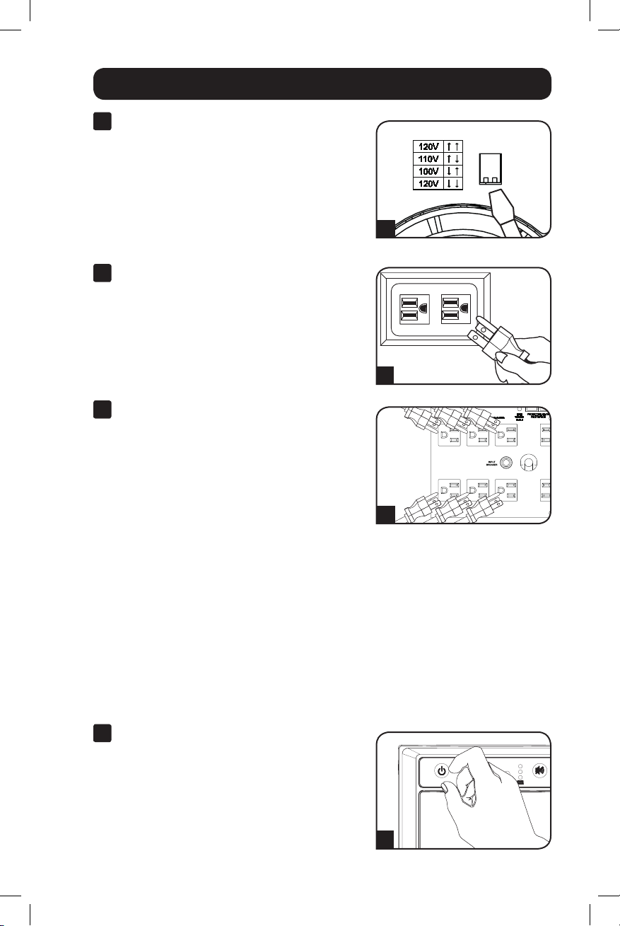
1
With the UPS disconnected from utility
power, use a small tool to set the
Voltage DIP Switch to match your
input voltage. (All models are preset
to the 120V setting.)
2
Plug the UPS into an outlet on a
dedicated circuit.
NOTE! after you plug the UPS into a live AC
outlet, the UPS will automatically charge its
batteries,* but will not supply power to its
outlets until it is turned ON.
* The BATTERY CHARGE LED will be the only LED
illuminated
3
Plug your equipment into the UPS.
Model SMC1500T: All outlets provide battery
backup and surge protection for computers,
monitors and other critical devices. Model
SMC1000T: Select outlets provide battery
backup and surge protection for computers,
monitors and other critical devices; select
outlets provide surge protection only for
printers and other nonessential devices.
Do not plug high-draw equipment such as
laser printers into the battery backup/
surge protection outlets.
Note: Your UPS is designed to support electronic
equipment only. You will overload the UPS if the total VA
rating for all equipment connected through the battery
backup/surge protection outlets exceeds the UPS's
Output Capacity. To find your equipment's VA ratings, look
on their nameplates. If the equipment is listed in amps,
multiply the number of amps by 120 to determine VA.
(Example: 1 amp × 120 = 120 VA). If you are unsure if
you have overloaded the UPS's outlets, see “OUTPUT
LOAD LEVEL” LED description.
1
SMC1500T model shown.
2
3
4
Turn the UPS ON.
Press and hold the “STANDBY” button for one
second. The alarm will beep once briefly after
one second has passed. Release the button.
Note: UPS system will function properly upon initial
startup; however, maximum runtime for the unit’s battery
will only be accessible after it has been charged for
24 hours.
3
14-12-046-93338B.indb 3 12/23/2014 10:21:53 AM
4
Page 4
Optional Installation
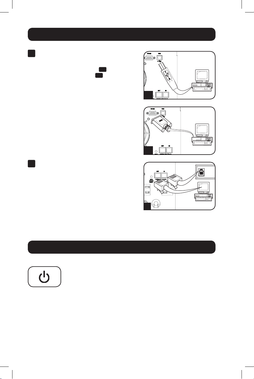
1
USB and RS-232 Serial
Communications
Use the included USB cable 1a and/or usersupplied DB9 serial cable 1b to connect the
communication port on your computer to the
communication port of your UPS. Install the
Tripp Lite PowerAlert® Software appropriate for
the operating system on your computer.
Consult your PowerAlert manual for more
information. PowerAlert software and
documentation are available for download at
www.tripplite.com.
2
Telephone/Network Protection Jacks
Your UPS has jacks that protect against surges
over a telephone line or a network dataline.
Using telephone network data cables, connect
your wall jack to the UPS jack marked “IN.”
Connect your equipment to the UPS jack
marked “OUT.” Make sure the equipment you
connect to the UPS's jacks is also protected
against surges on the AC line.
Not compatible with PoE (Power Over Ethernet)
applications.
1a
1b
2
Basic Operation
Buttons
“STANDBY” Button
• To turn the UPS ON: With the UPS plugged into a live AC wall
outlet,* press and hold the STANDBY button for about one
second.** Release the button. If utility power is absent, you can
"cold-start" the UPS (i.e.: turn it ON and supply power for a limited
time from its batteries***) by pressing and holding the STANDBY
button for about two seconds.**
• To turn the UPS OFF: With the UPS ON and receiving utility power,
press and hold the STANDBY button for one second.** Then unplug
the UPS from the wall outlet. The UPS will be completely OFF.
* After you plug the UPS into a live AC outlet, the UPS will automatically charge its
batteries, but will not supply power to its outlets until it is turned ON. ** The
alarm will beep once briefly after the indicated interval has passed. *** If fully
charged.
4
14-12-046-93338B.indb 4 12/23/2014 10:21:55 AM
Page 5

Basic Operation continued
“MUTE/TEST” Button
• To Silence (or “Mute”) UPS Alarms: Briefly press and release the
MUTE/TEST button.* Note: continuous alarms (warning you to
immediately shut down connected equipment) cannot be silenced.
• To Run a Self-Test: With your UPS plugged in and turned ON,
press and hold the MUTE/TEST button for two seconds.* Continue
holding the button until the alarm beeps several times and the UPS
performs a self-test. See “Results of a Self-Test” below. Note: you
can leave connected equipment on during a self-test. Your UPS,
however, will not perform a self-test if it is not turned ON (see
“STANDBY” Button description).
CAUTION! Do not unplug your UPS to test its batteries. this
will remove safe electrical grounding and may introduce a
damaging surge into your network connections.
Results of a Self-Test: The test will last approximately 10 seconds
as the UPS switches to battery to test its load capacity and battery
charge. The “POWER” LED will be flashing and the “OUTPUT LOAD
LEVEL” and “BATTERY CHARGE” LEDs will be lit and the UPS alarm
will sound.
• If the “OUTPUT LOAD LEVEL” LED remains lit red and the alarm
continues to sound after the test, the UPS's outlets are overloaded.
To clear the overload, unplug some of your equipment and run the
self-test repeatedly until the “OUTPUT LOAD LEVEL” LED is no longer
lit red and the alarm is no longer sounding.
CAUTION! Any overload that is not corrected by the user
immediately following a self-test may cause the UPS to shut
down and cease supplying output power in the event of a
blackout or severe brownout.
• If the “BATTERY WARNING” LED remains lit and the alarm continues
to sound after the test, the UPS batteries need to be recharged or
replaced. Allow the UPS to recharge continuously for 12 hours,
and repeat the self-test. If the LED remains lit, contact Tripp Lite
for service. If your UPS requires battery replacement, visit
www.tripplite.com/products/battery-finder to locate the specific
Tripp Lite replacement battery for your UPS.
* The alarm will beep once briefly after the indicated interval has passed.
5
14-12-046-93338B.indb 5 12/23/2014 10:21:55 AM
Page 6
Basic Operation continued
Indicator Lights
All Indicator Light descriptions apply when the UPS is plugged into a wall outlet
and turned ON.
“POWER” LED: This green LED lights continuously when the UPS is
ON and supplying connected equipment with AC power from a utility
source. The LED flashes and an alarm sounds (4 short beeps followed
by a pause) to indicate the UPS is operating from its internal batteries
during a blackout or severe brownout. If the blackout or severe
brownout is prolonged, you should save files and shut down your
equipment since internal battery power will eventually be depleted.
See “BATTERY CHARGE” LED description below.
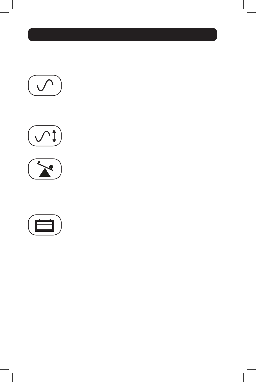
“VOLTAGE CORRECTION” LED: This green LED lights continuously
whenever the UPS is automatically correcting high or low AC voltage
on the utility line without the assistance of battery power. The UPS will
also emit a slight clicking noise. These are normal, automatic
operations of the UPS, no action is required on your part.
“OUTPUT LOAD LEVEL” LEDs: These multicolored LEDs indicate the
approximate electrical load of equipment connected to the UPS's AC
outlets: green (light load), yellow (medium load) and red (overload). If
the red LED is either illuminated continuously or flashing, clear the
overload immediately by unplugging some of your equipment from the
outlets until the yellow or green LED illuminates. CAUTION! Any
overload that is not corrected by the user immediately may cause the
UPS to shut down and cease supplying output power in the event of a
blackout or severe brownout.
“BATTERY CHARGE” LEDs: When the UPS is operating from utility
power, these LEDs indicate the approximate charge state of the UPS's
internal batteries: red indicates the batteries are beginning to charge;
yellow indicates the batteries are roughly midway through charging;
and green indicates the batteries are fully charged. When the UPS is
operating from battery power during a blackout or severe brownout,
these multicolor LEDs indicate the approximate amount of energy
(ultimately affecting runtime) that the UPS's batteries will provide: red
indicates a low level of energy; yellow indicates a medium level of
energy; and green indicates a high level of energy. Since the runtime
performance of all UPS batteries will gradually deplete over time, it is
recommended that you periodically perform a self-test (see “MUTE/
TEST” Button description) to determine the energy level of your UPS
batteries BEFORE a blackout or severe brownout occurs. During a
prolonged blackout or severe brownout, you should save files and shut
down your equipment since battery power will eventually be depleted.
When the red LED illuminates and an alarm sounds continuously, this
indicates that the UPS's batteries are nearly out of power and UPS
shutdown is imminent.
6
14-12-046-93338B.indb 6 12/23/2014 10:21:55 AM
Page 7
Basic Operation continued
“BATTERY WARNING” LED: this LED lights yellow and an alarm
sounds intermittently after you initiate a self test (See “MUTE/TEST”
Button description) to indicate the UPS batteries need to be
recharged or replaced. Allow the UPS to recharge continuously for 12
hours, and repeat the self-test. If the LED continues to light, contact
Tripp Lite for service. If your UPS requires battery replacement, visit
www.tripplite.com.
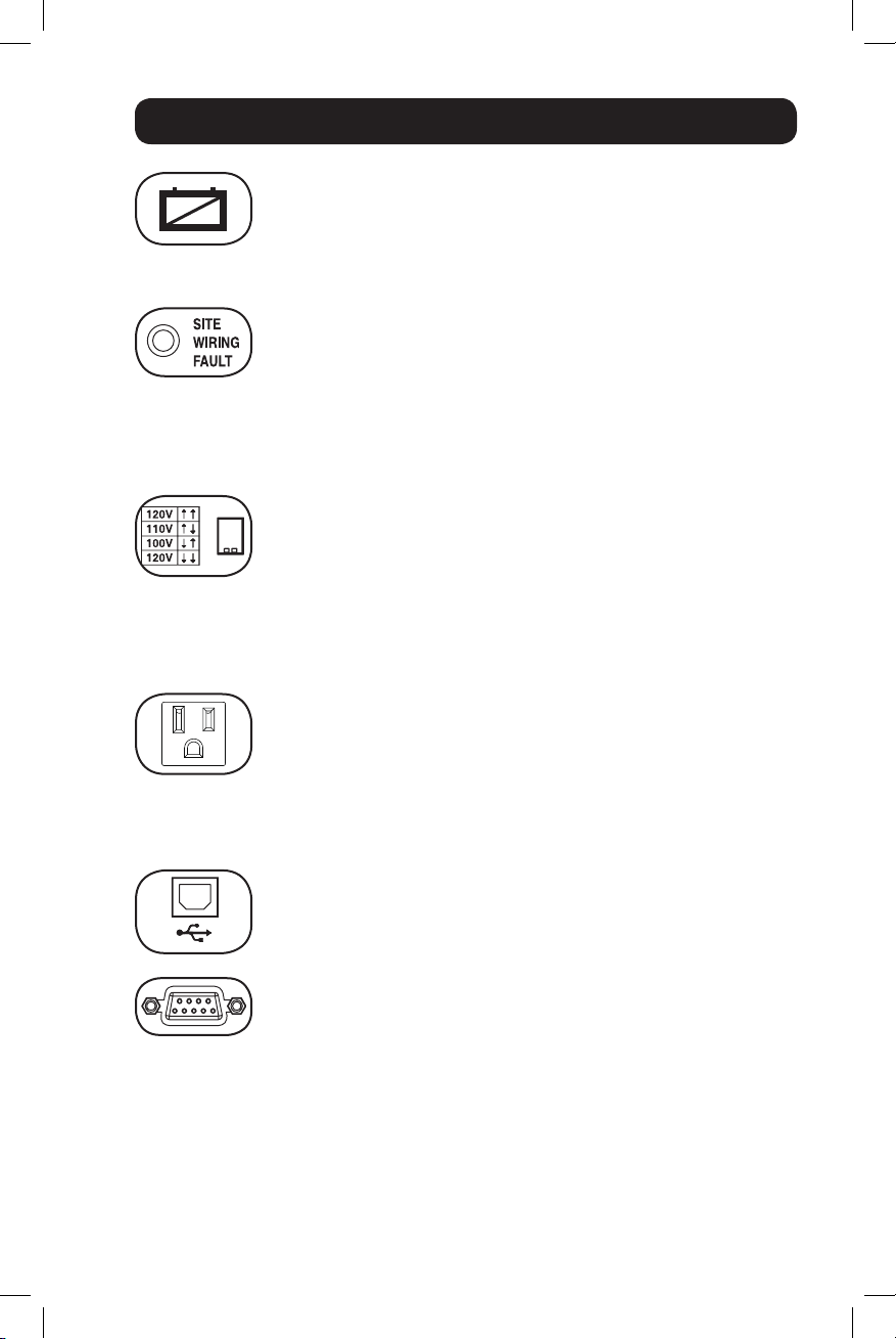
“SITE WIRING FAULT” LED: This yellow LED will be lit if the UPS
detects a problem with the wiring of the AC outlet you connect it to. If
this occurs, have the outlet inspected by a qualified electrician. Note
that while the UPS will detect many common wiring faults, including a
missing ground, reversed polarity and overloaded neutral circuits, it
cannot detect every conceivable wiring problem.
Other UPS Features
Voltage DIP Switch: This switch enables you to set the UPS to match
actual input voltage. If the Voltage DIP Switch is set above or below
input voltage, the UPS will treat the input as a continuous overvoltage
or undervoltage condition, and will automatically adjust input voltage
to match the Voltage DIP Switch setting. This will cause constant,
unnecessary wear on the UPS system. Note: The Voltage DIP
Switch must be set with the UPS turned OFF and disconnected
from utility power. If the switch is set while the UPS is
connected to utility power, the setting will not take effect.
AC Receptacles: These output receptacles provide your connected
equipment with AC line power during normal operation and battery
power during power outages. The UPS protects equipment connected
to these receptacles against damaging surges and line noise. Select
outlets provide both battery backup and surge protection for
computers, monitors and other critical devices plugged into these
outlets. Select outlets provide surge protection only for printers and
other non-essential devices that draw large amounts of power.
Communication Ports (USB and RS-232): These ports connect your
UPS to any workstation or server. Use with Tripp Lite's PowerAlert
Software and included cable to enable your computer to automatically
save open files and shut down equipment during a blackout. Also use
USB Port
RS-232
(DB9 port)
PowerAlert Software to monitor a wide variety of AC line power and
UPS operating conditions. Consult your PowerAlert Software manual or
contact Tripp Lite Customer Support for more information. See “USB
Communications” and “RS-232 Serial Communications” in the
“Optional Installation” section for installation instructions.
7
14-12-046-93338B.indb 7 12/23/2014 10:21:56 AM
Page 8
Basic Operation continued
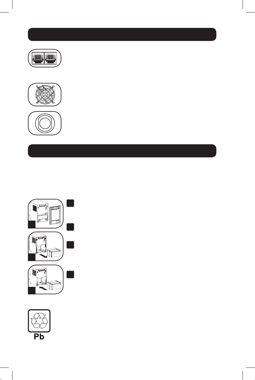
Telephone/Network Protection Jacks: These jacks protect your
equipment against surges over a telephone/network data line.
Connecting your equipment to these jacks is optional. Your UPS will
work properly without this connection.
Not compatible with PoE (Power Over Ethernet) applications.
Fan: The fan cools the UPS's internal components. It operates only
when the UPS is in battery backup mode, is charging its batteries or is
carrying a heavy electrical load.
Input Breaker (SMC1500T only): Protect your electrical equipment
from overcurrent draw from the UPS load. If this breaker trips, remove
some of the load, then reset it by pressing the breaker in.
Battery Replacement
Battery Replacement Door: Under normal conditions, the original battery in your UPS
will last several years. Battery replacement should be performed only by qualified service
personnel. Refer to “Battery Warnings” in the Safety section. Should your UPS require
battery replacement, visit Tripp Lite on the Web at http://www.tripplite.com/products/
battery-finder to locate the specific replacement battery for your UPS.
Carefully pull the front panel away from the UPS.
1
Place front panel on top of the unit. Remove the battery
support bar.
1
2
3
Remove old batteries.
2
Carefully pull the batteries from the UPS and disconnect them.
Connect new batteries.
3
Connect the new batteries in exactly the same manner as the old
ones: positive (red) connectors together and negative (black)
connectors together. Carefully push batteries back into the UPS.
Reassemble UPS.
4
Reinstall the battery support bar and replace the front panel.
UPS and Battery Recycling
Please recycle Tripp Lite Products. The batteries used in Tripp Lite products are sealed
Lead-Acid batteries. These batteries are highly recyclable. Please refer to your local codes
for disposal requirements.
You can call Tripp Lite for recycling info at 1-773-869-1234.
You can go the Tripp Lite Website for up-to-date information on recycling the batteries or any
Tripp Lite product.
Please follow this link: http://www.tripplite.com/support/recycling-program/
8
14-12-046-93338B.indb 8 12/23/2014 10:22:03 AM
Page 9

Storage & Service
Storage
CAUTION! Your UPS has an internal power source. Its outlets may still deliver current,
even after the UPS is unplugged, until the UPS is completely turned OFF (deactivated).
Before storing your UPS, turn it completely OFF: with the UPS ON and receiving utility
power, press and hold the STANDBY button for one second (an alarm will beep once
briefly after the interval has passed); then, unplug the UPS from the wall outlet. If you
store your UPS for an extended period of time, recharge the UPS batteries once every
three months: plug the UPS into a wall outlet; allow it to charge for 4 to 6 hours; and
then unplug it and place it back in storage. Note: after you plug the UPS in, it will
automatically begin charging its batteries; however, it will not supply power to its outlets
(see Quick Installation section). If you leave your UPS batteries discharged for an
extended period of time, they will suffer a permanent loss of capacity.
Service
A variety of Extended Warranty and On-Site Service Programs are available from
Tripp Lite. For more information on services, visit www.tripplite.com/support. Before
returning your UPS for service, follow these steps:
1. Review the installation and operation instructions in this manual to ensure that the
service problem does not originate from a misreading of the instructions.
2. If the problem continues, do not contact or return the UPS to the dealer. Instead,
visit www.tripplite.com/support.
3. If the problem requires service, visit www.tripplite.com/support and click the Product
Returns link. From here you can request a Returned Material Authorization (RMA)
number, which is required for service. A simple on-line form will ask for your unit’s
model and serial numbers along with other general purchaser information. The RMA
number, along with shipping instructions, will be emailed to you. Any damages
(direct, indirect, special or consequential) to the product incurred during shipment to
Tripp Lite or an authorized Tripp Lite service center are not covered under warranty.
Products shipped to Tripp Lite or an authorized Tripp Lite service center must have
transportation charges prepaid. Mark the RMA number on the outside of the
package. If the product is within its warranty period, enclose a copy of your sales
receipt. Return the product for service using an insured carrier to the address given
to you when you request the RMA.
9
14-12-046-93338B.indb 9 12/23/2014 10:22:03 AM
Page 10

Product Registration
Visit www.tripplite.com/warranty today to register your new Tripp Lite product. You'll be
automatically entered into a drawing for a chance to win a FREE Tripp Lite product!*
* No purchase necessary. Void where prohibited. Some restrictions apply. See website for details.
Regulatory Compliance
FCC Part 68 Notice (United States Only)
If your Modem/Fax Protection causes harm to the telephone network, the telephone company may
temporarily discontinue your service. If possible, they will notify you in advance. If advance notice isn't
practical, you will be notified as soon as possible. You will be advised of your right to file a complaint
with the FCC. Your telephone company may make changes in its facilities, equipment, operations or
procedures that could affect the proper operation of your equipment. If it does, you will be given
advance notice to give you an opportunity to maintain uninterrupted service. If you experience trouble
with this equipment's Modem/Fax Protection, please visit www.tripplite.com/support for repair/warranty
information. The telephone company may ask you to disconnect this equipment from the network until
the problem has been corrected or you are sure the equipment is not malfunctioning. There are no
repairs that can be made by the customer to the Modem/Fax Protection. This equipment may not be
used on coin service provided by the telephone company. Connection to party lines is subject to state
tariffs. (Contact your state public utility commission or corporation commission for information.)
Regulatory Compliance Identification Numbers
For the purpose of regulatory compliance certifications and identification, your Tripp Lite product has
been assigned a unique series number. The series number can be found on the product nameplate
label, along with all required approval markings and information. When requesting compliance
information for this product, always refer to the series number. The series number should not be
confused with the marketing name or model number of the product.
Tripp Lite follows a policy of continuous improvement. Product specifications are subject to change
without notice.
Note on Labeling
Two symbols are used on the label.
V~ : AC Voltage
V : DC Voltage
1111 W. 35th Street, Chicago, IL 60609 USA • www.tripplite.com
10
14-12-046-93338B.indb 10 12/23/2014 10:22:03 AM
Page 11

Manual del propietario
SmartPro® SMC Torre
Sistemas UPS inteligentes, interactivos
Entrada/salida de 100/110/120V • Salida de onda sinusoidal
Modelos: SMC1000T, SMC1500T
(Número de Serie: AGSM5384, AGSM7136)
No conveniente para los usos móviles.
Instrucciones de seguridad importantes 12
Instalación rápida 13
Instalación opcional 14
Operación básica 14
Reemplazo de batería 18
Almacenamiento y servicio técnico 19
Cumplimiento de las Normas 20
English 1
Français 21
1111 W. 35th Street, Chicago, IL 60609 USA • www.tripplite.com
Copyright © 2014 Tripp Lite. Todos los derechos reservados.
SmartPro® es una marca comercial registrada de Tripp Lite.
14-12-046-93338B.indb 11 12/23/2014 10:22:05 AM
11
Page 12

Instrucciones de seguridad importantes
GUARDE ESTAS INSTRUCCIONES
Este manual contiene instrucciones y advertencias que deben seguirse durante la
instalación, la operación y el almacenamiento de todos los UPS de Tripp Lite. La
falta de observar estas advertencias podría afectar su garantía.
Advertencias sobre la ubicación del UPS
• Instale su UPS bajo techo, lejos de la humedad, el calor, los contaminantes
conductores, el polvo o la luz solar directa.
• Para un mejor funcionamiento, mantenga la temperatura en el interior entre 32º F y
104º F (0º C y 40º C).
• Deje una cantidad adecuada de espacio alrededor de todos los lados del UPS para
una adecuada ventilación.
• No monte esta unidad con el panel frontal o con el panel trasero hacia abajo
(Bajo ningún ángulo o inclinación). Si lo monta de esta manera, inhibirá
seriamente el sistema de enfriamiento interno de la unidad; lo que finalmente
causará daños al producto que no están cubiertos por la garantía.
Advertencias sobre la conexión del UPS
• Conecte su UPS directamente a una toma de corriente de CA puesta a tierra
apropiadamente. No conecte el UPS a si mismo ya que podría dañarse.
• Asegúrese de usar para la instalación la protección adecuada contra sobrecorriente,
de acuerdo con la especificación de la clavija o del equipo.
• No modifique el enchufe del UPS ni emplee un adaptador que elimine su conexión a
tierra.
• No use cordones de extensión para conectar el UPS a una toma de CA.
• Los tomacorrientes eléctricos que suministran energía al equipo deben instalarse
próximos al equipo y ser fácilmente accesibles.
• Si el UPS recibe energía de un generador de CA accionado por motor, el generador
debe proporcionar una salida limpia y filtrada de grado computadora.
Advertencias sobre la conexión de equipos
• No utilice un UPS de Tripp Lite para aplicaciones de soporte de vida en las que el
funcionamiento defectuoso o una falla del mismo pudiera causar la falla o una
alteración importante en el funcionamiento de un dispositivo de soporte de vida.
• No conecte supresores de sobretensiones ni cordones de extensión a la salida de su
UPS. Esto puede sobrecargarlo y anular su garantía y la del supresor de
sobretensiones.
Advertencias sobre la batería
• Debido a que las baterías presentan un peligro de choque eléctrico y quemaduras por
las altas corrientes de cortocircuito, tome las precauciones adecuadas. No deseche
las baterías en un incinerador. No abra las baterías. No ponga los terminales de la
batería en corto o en puente con ningún objeto. Apague y desconecte el UPS antes
de reemplazar la batería. Sólo debe cambiar las baterías personal técnico
debidamente capacitado. Use herramientas con mangos aislados y reemplace las
baterías existentes con el mismo número y tipo de baterías nuevas (plomo-ácido
selladas). Las baterías del UPS son reciclables. Para los requisitos de desecho,
consulte sus códigos locales.
12
14-12-046-93338B.indb 12 12/23/2014 10:22:05 AM
Page 13

Instalación rápida
1
Con el UPS desconectado de la
energía de la red, use una
herramienta pequeña para ajustar el
conmutador DIP de voltaje de modo
que coincida con su voltaje de
entrada. (Todos los modelos están
ajustados a 120 V en forma
predeterminada.)
2
Conecte el UPS en una salida de un
circuito dedicado.
Nota: Después de conectar el UPS en un
tomacorrientes con corriente CA viva, el UPS
cargará sus baterías automáticamente,* pero
no suministrará energía a sus tomacorrientes
hasta que sea encendido.
* El LED BATTERY CHARGE (CARGA DE BATERÍA) será el
único iluminado.
3
Conecte sus equipos con el UPS
Modelo SMC1500T: Todas las salidas
proporcionan respaldo de batería y protección
contra sobretensiones para computadoras,
monitores y otros dispositivos críticos. Modelo
SMC1000T: Ciertas salidas proporcionan
respaldo de batería y protección contra
sobretensiones para computadoras, monitores
y otros dispositivos críticos; ciertas salidas
proporcionan protección contra sobretensiones
solo para impresoras y otros dispositivos no
indispensables.
No enchufe equipo de alto consumo como impresoras láser en los
tomacorrientes respaldados por batería y protección contra sobretensiones.
* Su UPS está diseñado para dar soporte únicamente a equipos de computación. Usted provocará
una sobrecarga del UPS si la potencia nominal en VA de todos los equipos que conecte supera la
Capacidad de Salida del UPS (vea las Especificaciones). Para averiguar la potencia nominal en VA de
sus equipos, consulte las placas de identificación. Si el equipo está expresado en amp, multiplique la
cantidad de amp por 120 para determinar los VA. (Ejemplo: 1 amp × 120 = 120 VA). Si no está
seguro de si ha sobrecargado las salidas del UPS, vea la descripción del LED "OUTPUT LOAD LEVEL"
(NIVEL DE CARGA DE SALIDA).
4
Encienda (ON) el UPS.
Presione y mantenga presionado el botón
“STANDBY” durante un segundo. La alarma
emitirá un pitido brevemente después de
pasado un segundo. Suelte el botón.
Nota: El sistema UPS funcionará correctamente en el
arranque inicial; no obstante, la autonomía máxima para
la batería de la unidad sólo será accesible después de
haberse cargado por 24 horas.
13
1
Se muestra el modelo SMC1500T.
2
3
4
14-12-046-93338B.indb 13 12/23/2014 10:22:05 AM
Page 14

Instalación opcional
1
Comunicaciones USB y serie RS-232
Use el cable USB incluido 1a y/o cable serial
DB9 1b suministrado por el usuario para
conectar el puerto de comunicación en su
computadora al puerto de comunicación de su
UPS. Instale en su computadora el Software
PowerAlert® de Tripp Lite apropiado al sistema
operativo de su computadora. Para más
información, consulte su manual de
PowerAlert. El programa y la documentación de
PowerAlert están disponibles para descarga en
www.tripplite.com.
2
Teléfono/gatos de conexión de red
Su UPS tiene conectores que lo protegen
contra sobretensiones en la línea telefónica.
Usando cordones adecuados para teléfono o
para red, conecte su conector de pared al
conector del UPS marcado “IN.” Cerciórese el
equipo que usted conecta a los gatos de UPS
se protege también contra oleadas en la línea
de C.A.
No compatible con aplicaciones PoE (Energía sobre Ethernet).
1a
1b
2
Operación básica
Botones (Panel frontal)
Botón “STANDBY” (Reserva)
• Para encender el UPS: Con el UPS conectado en una toma de CA
con energía*, presione y mantenga presionado el botón “STANDBY”
(Reserva) por un segundo.** Suelte el botón. Si no hay energía de
la red, puede "arrancar en frío" el UPS (es decir, encenderlo y
suministrar energía de sus baterías por un tiempo limitado***)
presionando y manteniendo presionado el botón “STANDBY”
(Reserva) durante un segundo.**
• Para apagar el UPS: Con el UPS encendido y recibiendo energía
de la red, presione y mantenga presionado el botón “STANDBY”
(Reserva) urante un segundo.** Luego desconecte el UPS de la
toma de corriente. El UPS se apagará.
* Después de conectar el UPS en una toma de CA con energía, el equipo (en
modo "Standby") cargará automáticamente sus baterías, pero no suministrará
energía a sus salidas hasta que sea encendido. ** La alarma emitirá un pitido
brevemente después de pasado el intervalo indicado. *** Si está completamente
cargada.
14
14-12-046-93338B.indb 14 12/23/2014 10:22:06 AM
Page 15

Operación básica continúa
Botón “MUTE/TEST” (Silencio/Prueba)
• Para silenciar las alarmas UPS: Presione brevemente el botón
MUTE/TEST (Silencio/Prueba) y luego suéltelo. Nota: las alarmas
continuas (que le advierten que debe apagar inmediatamente el
equipo conectado) no pueden ser silenciadas.
• Para ejecutar una auto-prueba: Con su UPS conectado y
encendido, presione y mantenga presionado el botón MUTE/TEST
(Silencio/Prueba) por dos segundos.* Siga presionando el botón
hasta que la alarma suene varias veces y el UPS realice una autoprueba. Vea “Resultados de una auto-prueba” más abajo. Nota:
Puede dejar equipos conectados durante una auto-prueba. Sin
embargo, el UPS, no realizará una auto-prueba si no está
encendido (vea la descripción del Botón "STANDBY").
¡PRECAUCIÓN! No desconecte su UPS para probar sus
baterías. Esto eliminaría la conexión de seguridad a tierra y
podría introducir una sobretensión dañina en sus conexiones
de red.
Resultados de una auto-prueba: La prueba durará cerca de 10
segundos mientras el UPS conmuta a batería para probar su
capacidad de carga y la recarga de la batería. El LED “POWER”
[Encendido] estará destellando y los LEDs “OUTPUT LOAD
LEVEL”[Nivel de Carga de Salida] y “BATTERY CHARGE” [Carga de
Batería] estarán encendidos y la alarma del UPS sonará.
• Si el LED "OUTPUT LOAD LEVEL" [Nivel de Carga de Salida]
permanece encendido en rojo y la alarma continúa sonando
después de la prueba, los tomacorrientes del UPS están
sobrecargados. Para eliminar la sobrecarga, desconecte algunos de
sus equipos y corra repetidamente el autodiagnóstico hasta que el
LED "OUTPUT LOAD LEVEL" [Nivel de Carga de Salida] ya no
permanezca encendido y la alarma ya no suene.
¡PRECAUCIÓN! Cualquier sobrecarga que no sea corregida por
el usuario inmediatamente después de una auto-prueba
puede causar que el UPS se apague y deje de suministrar
energía de salida en el caso de una falla del servicio eléctrico
o una baja de voltaje.
• Si el LED “BATTERY WARNING” (Advertencia de batería) sigue
encendido y la alarma continúa sonando después de la prueba, las
baterías del UPS deben recargarse o reemplazarse. Permita que el
UPS se recargue continuamente por 12 horas y repita la autoprueba. Si el LED permanece encendido, contacte con Tripp Lite
para obtener servicio. Si su UPS requiere el reemplazo de su
batería, visite www.tripplite.com para localizar la batería de
reemplazo Tripp Lite específica para su UPS.
* La alarma emitirá un pitido brevemente después de pasado el intervalo
indicado.
15
14-12-046-93338B.indb 15 12/23/2014 10:22:06 AM
Page 16

Operación básica continúa
Luces indicadoras
Todas las descripciones de luces indicadoras se aplican cuando el UPS está
conectado en un tomacorriente y encendido.
LED “POWER” (Alimentación): Este LED verde se enciende
permanentemente cuando el UPS está encendido y proporcionando
energía de CA al equipo conectado desde el suministro de red. El LED
destella y una alarma suena (4 pitidos cortos seguidos de una pausa)
para indicar que el UPS está operando con sus baterías internas
durante una falla del servicio eléctrico o una severa baja de voltaje. Si
la falla o la baja de voltaje es muy prolongada, debe guardar sus
archivos y apagar su equipo ya que la energía de la batería interna
finalmente se agotará. Vea la descripción del LED "BATTERY CHARGE"
(Carga de batería).
LED “VOLTAGE CORRECTION” (Corrección de voltaje): Este LED
verde se enciende en forma permanente cuando el UPS está
corrigiendo automáticamente el voltaje de CA alto o bajo en la línea
de la red sin la ayuda de energía de baterías. El UPS también emitirá
un ligero clic. Estas son operaciones normales y automáticas del UPS
y no requieren de ninguna acción de su parte.
LEDs “OUTPUT LOAD LEVEL” (NIVELDE CARGADE SALIDA): Estos
LEDs multicolor indica la carga eléctrica aproximada del equipo
conectado a las salidas de CA del UPS. Se encenderá desde verde
(carga ligera) a amarillo (carga media) y a rojo (sobrecarga) Si el LED
está rojo (ya sea iluminado permanentemente o destellando), elimine
la sobrecarga de inmediato desconectando algo de su equipo de las
salidas hasta que el LED cambie de rojo a amarillo (o verde).
¡PRECAUCIÓN! Cualquier sobrecarga que no sea corregida por el
usuario inmediatamente puede causar que el UPS se apague y deje
de suministrar energía de salida en el caso de un falla del servicio
eléctrico o una baja de voltaje.
LEDs “BATTERY CHARGE” (CARGA DE BATERÍA): Cuando el UPS
opera con la energía de la red, Estos LEDs multicolor indica el estado
aproximado de carga de las baterías internas del UPS; el rojo indica
que las baterías están comenzando a cargarse; el amarillo indica que
las baterías están aproximadamente a media recarga; y el verde indica
que las baterías están totalmente cargadas. Cuando el UPS opera con
energía de las baterías durante una falla del servicio eléctrico o una
baja de voltaje severa, este LED indica la cantidad aproximada de
energía (que a fin de cuentas afecta el tiempo de respaldo) que
proporcionarán las baterías del UPS; el rojo indica un bajo nivel de
energía, el amarillo un nivel mediano y el verde un nivel alto de energía.
Ya que el rendimiento del tiempo de respaldo de todas las baterías del
UPS se reducirá gradualmente, se recomienda realizar una auto-prueba
periódicamente (vea la descripción del botón MUTE/TEST (SILENCIO/
PRUEBA) para determinar el nivel de energía de las baterías de su UPS
ANTES de que ocurra una falla del servicio eléctrico o una baja de
voltaje severa. Durante una falla prolongada o una severa baja de
voltaje, debe guardar sus archivos y apagar su equipo ya que la energía
de baterías se agotará finalmente. Cuando el LED se enciende rojo y
una alarma suena en forma continua, indica que las baterías del UPS
están casi sin energía y es inminente que el UPS se apague.
16
14-12-046-93338B.indb 16 12/23/2014 10:22:06 AM
Page 17

Operación básica continúa
LED “BATTERY WARNING” (Advertencia de batería): Este LED se
enciende rojo y una alarma suena en forma intermitente después de
iniciar una auto-prueba (vea la descripción del botón “MUTE/TEST”
(SILENCIO/PRUEBA)) para indicar que las baterías del UPS deben ser
recargadas o reemplazadas. Permita que el UPS se recargue
continuamente por 12 horas y repita la auto-prueba. Si el LED sigue
encendido, contacte con Tripp Lite para que le brinden servicio. Si su
UPS requiere el reemplazo de su batería,visite www.tripplite.com
LED “SITE WIRING FAULT” (Falla del cableado local): Este LED rojo
se encenderá si el UPS detecta algún problema con el cableado del
tomacorriente al que se está conectando. En este caso, haga revisar
el tomacorriente por un electricista calificado. Aunque el UPS puede
detectar muchas fallas communes de cableado, como una tierra
ausente, polaridad invertida y circuitos del neutro sobrecargados, no
puede detectar todos los problemas de cableado.
Otras funciones del UPS
Conmutador DIP de voltaje: Este conmutador le permite configurar
el no-break para el voltaje real de entrada. Si el conmutador DIP de
voltaje se fija por encima o por debajo del voltaje de entrada, el
no-break interpretará la entrada como un sobrevoltaje permanente o
como una condición de bajo voltaje, y ajustará automáticamente el
voltaje de entrada para que coincida con el ajuste del conmutador
DIP de voltaje. Esto puede causar un desgaste constante e
innecesario en el no-break. Nota: El conmutador DIP de voltaje
debe fijarse con el no-break apagado (OFF) y desconectado de
la alimentación de la red. Si el conmutador es fijado mientras el
no-break está conectado para utilizar energía, el ajuste no
entrará en efecto.
Tomas de CA: Estas salidas proporcionan energía de la línea de
corriente alterna a su equipo conectado durante operación normal, y
energía de baterías durante fallas del servicio eléctrico y bajas de
voltaje. El UPS protege al equipo conectado a estas tomas contra
sobretensiones perjudiciales y ruido en la línea. Tomacorrientes selectos
proporcionan tanto respaldo por batería como protección contra
sobretensiones para computadoras, monitores y otros dispositivos
críticos enchufados en estos tomacorrientes. Las salidas exclusivas
proporcionarán protección contra sobretensiones solamente; conecte
su impresora y otros dispositivos no esenciales aquí.
Puertos de comunicaciones (USB o RS-232): Estos puertos
conectan su UPS a cualquier estación de trabajo o servidor. Use con
el Software PowerAlert de Tripp Lite y el cable incluido para habilitar
su computadora para guardar automáticamente archivos abiertos y
USB Port
RS-232
(DB9 port)
apague el equipo durante un apagón. También utilice PowerAlert para
vigilar una amplia variedad de condiciones de operación de la energía
de la línea de CA y del UPS. Consulte su manual de PowerAlert o
contacte con el Soporte al cliente de Tripp Lite para mayor
información. Consulte “Comunicaciones USB y serie RS-232” en la
sección “Instalación opcional” para obtener la información sobre las
instrucciones de instalación.
17
14-12-046-93338B.indb 17 12/23/2014 10:22:07 AM
Page 18

Operación básica continúa
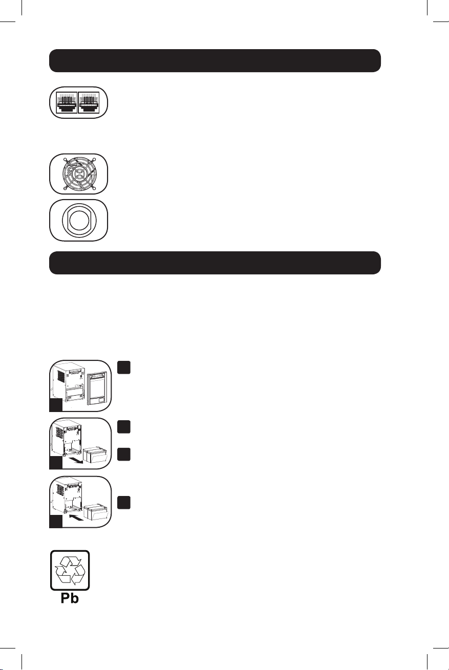
Conectores de protección teléfono/red: Estos conectores protegen
su equipo contra sobretensiones a través de de teléfono/datos de red.
La conexión de su equipo con estos conectores es opcional. Su UPS
funcionará correctamente sin esta conexión.
No compatible con aplicaciones PoE (Energía sobre Ethernet).
Ventilador: El ventilador enfría los componentes internos del UPS.
Sólo opera cuando el UPS está en modo de respaldo de batería,
durante la carga de sus baterías o lleva una carga pesada de
electrical.
Interruptor automático (SMC1500T solamente): Protegen su
circuito eléctrico contra sobrecarga al UPS. Si uno de estos
interruptores dispara, retire algo de carga y restablézcalo presionando
el interruptor.
Reemplazo de batería
Puerta de reemplazo de la batería: En condiciones normales, las baterías originales
de este sistema UPS tienen varios años de vida útil. Sólo deberá reemplazar la batería
personal técnico calificado. Véase “Advertencias sobre las baterías”, en la sección sobre
seguridad. Si requiere reemplazar la batería de su UPS, visite Tripp Lite en la web en
http://www.tripplite.com/products/battery-finder para localizar la batería de reemplazo
específica para su UPS.
Tire cuidadosamente del panel frontal, hacia afuera y
1
retirándolo del UPS.
Coloque el panel frontal en la parte superior del UPS.
1
2
3
Reciclaje de UPS y Baterías
Por favor recicle los productos de Tripp Lite. Las baterías usadas en los productos de
Tripp Lite son baterías selladas de Plomo-Ácido. Estas baterías son altamente reciclables.
Refiérase por favor a sus códigos locales para requerimientos de desecho.
Puede llamar a Tripp Lite para reciclar, información al 1-773-869-1234.
Puede acudir al sitio Web de Tripp Lite en busca de información actualizada sobre el
reciclaje de baterías o cualquier producto de Tripp Lite. Siga por favor este enlace:
http://www.tripplite.com/support/recycling-program/
Desbloquee y baje la puerta de la batería.
Quite las baterías viejas.
2
Tire con cuidado de las baterías del UPS y los desconecta.
Conecte las nuevas baterías
3
Conecte las nuevas baterías en la misma forma que las antiguas,
es decir, conectores positivos (rojos) juntos y terminales
negativos (negros) juntos. Empuje con cuidado la espalda nueva
de baterías en el UPS.
Reensamble UPS.
4
Reemplace la barra de apoyo de batería y el entrepaño anterior.
18
14-12-046-93338B.indb 18 12/23/2014 10:22:13 AM
Page 19

Almacenamiento y servicio técnico
Almacenamiento
¡PRECAUCIÓN! Su UPS tiene una fuente de energía interna. Sus salidas aún pueden
proporcionar corriente, incluso después que el UPS esté desconectado, a menos que
esté completamente apagado (desactivado). Antes de almacenar su UPS, apáguelo:
Con el UPS encendido y recibiendo energía de la red, presione y mantenga presionado
el botón “STANDBY” (Reserva) por un segundo (una alarma emitirá un pitido
brevemente después de dicho intervalo); luego, desconecte el UPS del tomacorriente de
pared. Si va a almacenar su UPS por un tiempo prolongado, debe recargar sus baterías
cada tres meses; para hacerlo, conecte el UPS en un tomacorriente y deje que las
baterías se carguen por 12 horas y luego desconecte el UPS y guárdelo nuevamente.
Nota: Después de conectar su UPS, automáticamente comenzará a cargar sus baterías,
pero no suministrará energía a sus salidas (vea la sección Instalación rápida) Si deja
descargadas las baterías del UPS durante un tiempo prolongado, sufrirán una pérdida
de capacidad permanente.
Servicio
También están disponibles una gran variedad de Programas de Garantía Extendida y
Servicio En Sitio por parte de Tripp Lite. Para información adicional acerca de servicios,
visite www.tripplite.com/support.
Antes de enviar su UPS para que le presten servicio, siga los siguientes pasos:
1. Verifique las instrucciones de instalación y operación en este manual para
asegurarse que el problema de servicio no sea causado por una mala interpretación
de las instrucciones.
2. Si el problema continúa, no contacte con el distribuidor ni devuelva el UPS. En su
lugar, visite www.tripplite.com/support.
3. Si el problema requiere de servicio, visite www.tripplite.com/support y haga click en
la liga Product Returns. Desde aquí usted puede solicitar un número de Autorización
de Devolución de Mercancía (RMA) que se requiere para el servicio. Una sencilla
forma en línea solicitará los números de modelo y serie de su unidad junto con otra
información general del comprador. El número de RMA junto con las instrucciones
de embarque le serán enviadas por correo electrónico. Cualquier daño (directo,
indirecto, especial o consecuencial) al producto incurrido durante el embarque a
Tripp Lite o un Centro de Servicio Autorizado de Tripp Lite no está cubierto bajo la
garantía. Los productos embarcados a Tripp Lite o un Centro de Servicio Autorizado
de Tripp Lite deben tener los cargos del transporte prepagados. Marque el número
de RMA en el exterior del empaque. Si el producto está dentro del período de
garantía, adjunte una copia de su recibo de venta. Regrese el producto para servicio
usando un transportista asegurado a la dirección proporcionada a usted cuando
solicitó la RMA.
19
14-12-046-93338B.indb 19 12/23/2014 10:22:13 AM
Page 20

Cumplimiento de las Normas
Cumplimiento de las normas de los números de identificación
Para fines de identificación y certificación del cumplimiento de las normas, su producto Tripp Lite tiene
asignado un número de serie único. Puede encontrar el número de serie en la etiqueta de la placa de
identificación del producto, junto con los símbolos de aprobación e información requeridos. Al solicitar
información sobre el cumplimiento de las normas para este producto, siempre mencione el número de
serie. El número de serie no debe ser confundido con el nombre de identificación ni con el número de
modelo del producto.
Tripp Lite tiene una política de mejoramiento continuo. Las especificaciones están sujetas a cambio sin
previo aviso.
Nota sobre etiquetado
Se usan dos símbolos en la etiqueta.
V~ : Voltaje de CA
V : Voltaje de CC
1111 W. 35th Street, Chicago, IL 60609 USA • www.tripplite.com
20
14-12-046-93338B.indb 20 12/23/2014 10:22:13 AM
Page 21

Manuel du propriétaire
Tour SmartPro® SMC
Systèmes UPS intelligent, en attente active
Entrée/Sortie 100/110/120 V • Puissance sinusoïdale
Modèles : SMC1000T, SMC1500T
Numéro de série : AGSM5384, AGSM7136)
Non approprié aux applications mobiles.
Directives de sécurité importantes 22
Installation rapide 23
Installation en option 24
Fonctionnement de base 24
Remplacement des piles 28
Entreposage et service 29
Conformité réglementaire 30
English 1
Español 11
1111 W. 35th Street, Chicago, IL 60609 USA • www.tripplite.com
Copyright © 2014 Tripp Lite. Tous droits réservés.
SmartPro® est une marque de commerce enregistrée de Tripp Lite.
14-12-046-93338B.indb 21 12/23/2014 10:22:15 AM
21
Page 22

Directives de sécurité importantes
CONSERVER CES DIRECTIVES
Ce manuel contient des directives importantes que vous devez respecter durant
l'installation, l'utilisation et l'entreposage de tous les systèmes UPS Tripp Lite. Ne pas
tenir compte de ces mises en garde pourrait affecter votre garantie.
Avertissements concernant l'emplacement de l'ASI
• Installez votre ASI à l'intérieur, à l'abri de la chaleur ou de l'humidité excessive, des
contaminants conducteurs, de la poussière ou de l'ensoleillement direct.
• Pour un meilleur rendement, maintenez la température intérieure entre 0º C et 40º C
(32º F et 104º F).
• Laissez suffisamment d'espace de chaque côté de l'ASI pour permettre une ventilation
adéquate.
• Ne pas monter l'unité avec son panneau avant ou arrière à l'envers (quelque
soit l'angle). Monter de cette façon va entraver sérieusement le refroidissement
interne de l'unité, endommageant le produit non couvert sous garantie.
Avertissements concernant le branchement de l'ASI
• Branchez votre ASI directement à une prise de courant correctement mise à la terre.
Ne branchez pas l'ASI sur lui-même, vous pourriez l'endommager.
• S'assurer d'utiliser la bonne protection contre les surintensités pour l'installation,
conformément aux valeurs nominales de la fiche et de l'équipement.
• Ne modifiez pas la prise de l'ASI et n'utilisez jamais d'adaptateur qui éliminerait la
prise de terre de l'ASI.
• N'utilisez pas de rallonge électrique pour brancher l'ASI à la prise de courant.
• Les prises électriques qui alimentent l'équipement doivent être installées à proximité
de l'équipement et être facilement accessibles.
• Si l'ASI reçoit son alimentation d'un moteur-générateur à courant alternatif, ce dernier
doit fournir une énergie de qualité informatique propre et filtrée.
Avertissements concernant le branchement d'équipement
• N'utilisez pas les systèmes ASI Tripp Lite avec des appareils de maintien des fonctions
vitales sur lesquels une défectuosité ou une défaillance du système ASI Tripp Lite
pourrait causer la défaillance ou une altération significative du rendement d'un tel
appareil de maintien des fonctions vitales.
• Ne pas brancher d'éliminateurs de surtension ou de cordon prolongateur à la sortie
de votre UPS. Cela pourrait surcharger l'UPS et annuler les garantie de l'éliminateur
de surtension et de l'UPS.
Avertissements concernant le branchement d'équipement
• Parce que les batteries présentent un risque de choc électrique et de courant de
court-circuit élevé, prenez les précautions nécessaires. Ne pas jeter les batteries au
feu. Ne pas ouvrir les batteries. Ne pas établir de court-circuit ou de pont entre les
bornes de la batterie avec un quelqconque objet. Débrancher et éteindre l'UPS avant
de remplacer la batterie. Le remplacement de la batterie doit être confié à du
personnel de service qualifié. Utiliser des outils ayant des poignées isolées et
remplacer les batteries existantes par des batteries neuves du même numéro et du
même type (batterie sans entretien). Les batteries UPS sont recyclables. Se reporter
aux codes locaux pour les exigences en matière d'élimination.
22
14-12-046-93338B.indb 22 12/23/2014 10:22:15 AM
Page 23

Installation rapide
1
Une fois le UPS débranché de
l'alimentation de service, utilisez un
petit outil pour régler l'interrupteur de
diminution de tension afin qu'il
corresponde à votre tension d'entrée.
(Tous les modèles sont préréglés
selon des paramètres de 120 V).
2
Branchez le UPS dans la prise d'un
circuit dédié.
REMARQUE! Après le branchement de l'UPS
dans une prise de secteur, l'UPS mettra
automatiquement ses batteries en charge,*
n'alimentera pas ses sorties en électricité
jusqu'à ce qu'il soit mis en marche.
* Le Voyant DEL BATTERY CHARGE (charge de la
batterie) sera le seul voyant alluméé.
3
Brancher votre équipement à l'UPS.
Modèle SMC1500T : toutes les prises
fournissent secours de batterie et
parasurtension pour les ordinateurs, les
moniteurs et autres dispositifs essentiels.
Modèle SMC1000T : Des prises choisies
fournissent secours de batterie et
parasurtension aux ordinateurs, moniteurs et
autres dispositifs essentiels; des prises choisies
fournissent parasurtension aux imprimantes et
aux autres dispositifs accessoires.
Ne branchez aucun équipement qui consomme beaucoup de courant,
comme les imprimantes laser, aux prises alimentées par des batteries de
secours et protégées par des parasurtenseurs.
* Votre UPS est conçu uniquement pour prendre en charge des appareils informatiques. Vous
surchargerez l'UPS si la valeur nominale totale de voltampères (VA) pour tous les équipements que
vous branchez dépasse la puissance de sortie de l'UPS (voir les Caractéristiques techniques). Pour
trouver la valeur nominale en VA de vos appareils, verifies la plaque commerciale. Si la valeur de
l'appareil est donnée en ampères, multipliez le chiffre de l'intensité (en Ampères) par 120 pour
déterminer la valeur nominale en VA. (Exemple : 1 A × 120 = 120 VA). Si vous n'êtes pas sûr
d'avoir surchargé ou non les prises de votre UPS, consultez la description de la DÉL " NIVEAU DE
CHARGE DE LA SORTIE " (OUTPUT LOAD LEVEL).
4
Mettre l'UPS sous tension.
Appuyer sur le bouton “STANDBY” et le
maintenir pendant une seconde. L'alarme
bippera une fois brièvement après une seconde.
Relâcher le bouton.
Note : L'onduleur fonctionnera correctement lors du
démarrage initial; cependant, la durée de fonctionnement
maximale de la batterie de l'appareil ne sera accessible
qu'après avoir été chargée pendant 24 heures.
23
1
Modèle SMC1500T illustré.
2
3
4
14-12-046-93338B.indb 23 12/23/2014 10:22:16 AM
Page 24

Installation en option
1
Ports de communication de série USB
et RS-232
Utiliser le câble USB 1a et/ou le câble de
série DB9 fourni par l'utilisateur 1b pour
connecter le port de communication de
l'ordinateur au port de communication de
l'onduleur. Installer le logiciel PowerAlert de
Tripp Lite compatible avec le système
d'exploitation de l'ordinateur. Veuillez consulter
le manuel PowerAlert pour obtenir plus
d'informations. Le logiciel PowerAlert et la
documentation peuvent être téléchargés en
suivant ce lien www.tripplite.com.
2
Téléphoner/Crics de Protection de
Réseau
Votre UPS est doté de prises qui protègent des
surtensions de lignes téléphoniques. Avec les
fils de téléphone ou fils réseaux appropriés,
branchez votre prise murale à la prise UPS
marquée “IN” (entrée). Assurer que
l'équipement que vous connectez aux crics
d'UPS est aussi protégé contre bondit sur la
ligne de courant alternatif.
Non compatible avec les ports Ethernet alimentés en courant.
1a
1b
2
Fonctionnement de base
Boutons
Botón “ STANDBY ” (Attente)
• Pour mettre en marche l'UPS : L'UPS étant branché dans une
prise murale de secteur, appuyer sur le bouton “ STANDBY ” et le
maintenir durant une seconde. ** Relâcher le bouton. S'il n'y a pas
de courant, vous pouvez mettre en marche l'UPS “ à froid ”
(c.-à-d. le mettre en marche et l'alimenter pendant un court
moment à partir de ses batteries*) en appuyant sur le bouton
“ STANDBY ” et en le maintenant pendant une seconde.**
• Pour arrêter l'UPS : l'UPS en marche et alimenté par le courant de
secteur , appuyer sur le bouton “ STANDBY ” et le maintenir
pendant une seconde.** Débrancher ensuite l'UPS de la prise
murale. L'UPS sera alors à l'arrêt complet.
* Après le branchement de l'UPS dans une prise de secteur, l'UPS (en mode
"Standby") mettra automatiquement ses batteries en charge, mais ne fournira pas
de courant à ses prises tant qu'il ne sera pas mis en marche. ** L'alarme bippera
une fois brièvement après l'intervalle indiqué. *** Si la charge est pleine.
24
14-12-046-93338B.indb 24 12/23/2014 10:22:16 AM
Page 25

Fonctionnement de base suite
Bouton SOURDINE/TEST
• Pour réduire au silence (ou “ mettre en sourdine ”) les
alarmes de l'UPS : Appuyer brièvement sur le bouton SOURDINE/
TEST et le relâcher. Note : Les alarmes continues (vous avertissant
de mettre immédiatement hors tension l'équipement connecté) ne
peuvent pas être mises en sourdine.
• Pour faire un auto-test : Votre UPS étant branché et en marche,
appuyer sur le bouton SOURDINE/TEST pendant deux secondes.*
Continuer à appuyer sur le bouton jusqu'à ce que l'alarme bippe
plusieurs fois et que l'UPS exécute un autotest. Voir ci-dessous
“ Résultats d'un autotest ”. Remarque : Vous pouvez laisser votre
équipement branché pendant un auto-test. Cependant, votre UPS
n'exécutera pas d'auto-test s'il n'est pas mis en marche (voir la
description du bouton “ STANDBY ”).
ATTENTION! Ne pas débrancher votre UPS pour tester ses
batteries. Cela supprimera la mise à la terre électrique
sécuritaire et peut entraîner une surtension dangereuse pour
les connexions de votre réseau.
Résultats d'un autotest : Le test durera environ 10 secondes, le
temps que l'UPS passe sur batteries pour vérifier sa puissance et sa
charge. La DEL « Power » clignotera et les DEL « OUTPUT LOAD
LEVEL » (niveau de charge) et « BATTERY CHARGE » (charge de la
batterie) seront allumées et l'alarme de l'onduleur se fera entendre.
• Si la DEL « OUTPUT LOAD LEVEL » (niveau de charge de sortie)
rouge demeure allumée et si l'alarme continue à se faire entendre
après le test, les prises de l'onduleur sont surchargées. Pour
éliminer la surcharge, débranchez certains de vos appareils et
effectuez l'autotest à plusieurs reprises jusqu'à ce que la DEL «
OUTPUT LOAD LEVEL » rouge s'éteigne et que l'alarme s'arrête.
ATTENTION! Toute surcharge non corrigée immédiatement par
l'utilisateur après l'auto-test peut entraîner l'arrêt de l'UPS et
empêcher l'alimentation électrique en cas de panne ou de
baisse de tension.
• Si le voyant DEL “ BATTERYWARNING (Avertissement batterie) ”
reste allumé et que l'alarme continue de sonner après le test, les
batteries de l'UPS doivent être rechargées ou remplacées. Laisser
l'UPS en charge continue pendant 12 heures et recommencer
l'autotest. Si le voyant DEL reste allumé, communiquer avec Tripp
Lite pour le service. Si votre UPS nécessite un remplacement de
batterie, rendez visite à Tripp Lite à www.tripplite.com pour trouver
la batterie de remplacement spécifique pour votre UPS.
* L'alarme bippera une fois brièvement après l'intervalle indiqué.
25
14-12-046-93338B.indb 25 12/23/2014 10:22:16 AM
Page 26

Fonctionnement de base suite
Voyants indicateurs
Toutes les descriptions de voyants indicateurs s'appliquent lorsque l'UPS est
branché sur une prise murale et mis sous tension.
Voyant DEL “ POWER ” : Ce voyant DEL vert est continuellement
allumé pour indiquer que l'UPS est sous tension et alimente votre
équipement en courant alternatif à partir du secteur. Le voyant DEL
clignote et l'alarme sonne (4 bips courts suivis d'une pause) pour
indiquer que l'UPS fonctionne à partir de ses batteries pendant une
panne ou une baisse de tension sévère. Si la panne ou la baisse de
tension se prolonge, vous devez sauvegarder vos fichiers et mettre
votre équipement hors tension car la puissance des batteries va finir
par baisser. Voir ci-dessous la description du voyant DEL “ BATTERY
CHARGE (Charge de la batterie) ”.
Voyant DEL “ VOLTAGE CORRECTION (Correction du voltage) ” :
Ce voyant DEL vert reste continuellement allumé chaque fois que
l'UPS corrige automatiquement le voltage c.a. du secteur sans
l'assistance de la puissance de la batterie. L'UPS émettra aussi un
léger cliquètement. Ce sont des opérations normales et automatiques
de l'UPS; vous n'avez rien à faire.
Voyants DEL “ OUTPUT LOAD LEVEL ” : Ces multicolore voyants DEL
à plusieurs couleurs indique la charge électrique approximative de
l'équipement branché sur les prises c.a. de l'UPS. Il passera de vert
(charge légère) à jaune (charge normale) à rouge (surcharge) si le
voyant Del est rouge (soit allumé en continu, soit clignotant), éliminer
la surcharge immédiatement en débranchant des prises une partie de
votre équipement jusqu'à ce que le voyant DEL rouge passe au jaune
(ou au vert). ATTENTION! Toute surcharge non corrigée immédiatement
par l'utilisateur peut entraîner l'arrêt de l'UPS et empêcher
l'alimentation électrique en cas de panne ou de baisse de tension.
Voyants DEL “ BATTERY CHARGE ” : Quand l'UPS fonctionne à partir
du secteur, ce voyant DEL indique l'état approximatif de la charge des
batteries de l'UPS : Rouge indique le début de la charge des batteries,
jaune que les batteries sont à peu près à mi-charge et vert que la
charge est pleine. Quand l'UPS fonctionne sur la puissance des
batteries pendant une panne ou une baisse de tension sévère, ces
multicolore voyants DEL indique la quantité approximative d'énergie
(affectant en fin de compte la durée de fonctionnement) que les
batteries de l'UPS peuvent fournir : Rouge indique un faible niveau
d'énergie, jaune un niveau moyen et vert un niveau élevé d'énergie.
Étant donné que la performance de la durée de fonctionnement de
toutes les batteries de l'UPS vont graduellement diminuer avec le
temps, il est recommandé d'exécuter régulièrement un autotest (voir
la description du bouton MUTE/TEST) pour déterminer le niveau
d'énergie des batteries de votre UPS AVANT une panne ou une baisse
de tension sévère. Pendant une panne ou une baisse de tension
prolongées, vous devez sauvegarder vos fichiers et éteindre votre
équipement car la puissance des batteries va finir par baisser. Si le
voyant DEL passe au rouge et que l'alarme sonne sans arrêt, cela
indique que les batteries de l'UPS sont presque à plat et que
l'extinction de l'UPS est imminente.
26
14-12-046-93338B.indb 26 12/23/2014 10:22:16 AM
Page 27

Fonctionnement de base suite
Voyant DEL “ BATTERY WARNING ” (Avertissement de la batterie) :
Ce voyant DEL s'allume en jaune et une alarme sonne de façon
intermittente après qu'un autotest ait été enclenché (voir la
description du bouton MUTE/TEST) pour indiquer que les batteries ont
besoin d'être rechargées ou changées. Laisser l'UPS en charge
continue pendant 12 heures et recommencer l'autotest. Si le voyant
DEL reste allumé, communiquer avec Tripp Lite pour le service. Si
votre UPS nécessite un remplacement de batterie, rendez visite à
Tripp Lite à www.tripplite.com/ support/battery/index.cfm pour trouver
la batterie de remplacement spécifique pour votre UPS.
TÉMOIN “ SITE WIRING FAULT ” : Ce témoin jaune s'allume si l'ASI
détecte un problème avec le câblage de la prise de courant à laquelle
il est branché. Si ceci se produit, faites inspecter la prise de courant
par un électricien qualifié. Veuillez noter que même si l'ASI détecte la
plupart des défaillances de câblage, dont une mise à la terre
manquante, une polarité inversée et des circuits neutres surchargés, il
ne peut détecter tous les problèmes de câblage possibles.
Autres caractéristiques de l'UPS
Commutateur DIP de tension : Ce commutateur vous permet de
régler la tension de l'onduleur UPS à la tension réelle d'entrée Si le
commutateur DIP de tension est réglé à une tension supérieure ou
inférieure à celle de l'entrée, l'onduleur traitera l'entrée comme un
état de surtension ou de subtension et ajustera automatiquement la
tension d'entrée pour qu'elle corresponde au réglage du commutateur
DIP de tension.Cela entraînera une usure constante et inutile sur le
système UPS. Nota : Le commutateur DIP de tension doit être
réglé avec l'onduleur UPS éteint et déconnecté du courant de
secteur. Si le commutateur est réglé pendant que l'onduleur est
connecté au courant de secteur, le réglage n'aura aucun effet.
Prises (c.a.) : Ces prises de sortie fournissent une puissance de ligne
c.a. à vos appareils branchés sur l'UPS lors d'un fonctionnement
normal et fournissent du courant provenant des batteries à ces
mêmes appareils pendant les coupures de courant. Certaines sorties
fournissent la batterie de secours et une protection contre les
surtensions pour les ordinateurs, les écrans et autres appareils
critiques branchés dans ces sorties. Des prises à cet effet fourniront
seulement une protection contre les surtensions; y brancher votre
imprimante et autres dispositifs non essentiels.
Ports de communications (USB et RS-232) : Ces ports connectent
votre UPS à tout serveur ou tout poste de travail. Utilisez le logiciel
PowerAlert de Tripp Lite avec les câbles fournis afin de permettre à
votre ordinateur d'enregistrer automatiquement les fichiers ouverts et
USB Port
RS-232
(DB9 port)
d'éteindre les appareils lors d'une panne de courant. Utilisez
également le logiciel PowerAlert pour surveiller toute une gamme de
puissances de ligne c.a. et les conditions de fonctionnement de l'UPS.
Consultez le manuel de votre logiciel PowerAlert ou communiquez
avec l'assistance technique de Tripp Lite pour plus d'informations. Voir
“ Communications USB ” et “ Communications série RS-232 ” dans
la section “ Installation facultative ” pour les instructions d'installation.
27
14-12-046-93338B.indb 27 12/23/2014 10:22:17 AM
Page 28
Fonctionnement de base suite
Prises de protection ligne téléphone/réseau : Cesv prises
protègent votre équipement contre les surtensions des lignes de
transmission de téléphone/réseau, selon le modèle. Brancher vos
équipements à ces prises est optionnel. Votre l'ASI fonctionnera
correctement même sans cette connexion.
Non compatible avec les ports Ethernet alimentés en courant.
Ventilateur : Le ventilateur refroidit les composants internes du UPS.
Il fonctionne seulement lorsque le UPS est en mode pile de secours,
en cours de recharge de ses piles ou porte un chargement lourd de
electrical.
Disjoncteurs d'entrée (SMC1500T seulement) : Protègent votre
circuit électrique d'une surintensité de la charge de votre UPS. Si ces
disjoncteurs sautent, enlever une partie de la charge, puis les
réenclencher.
Remplacement des piles
Porte de remplacement de batterie : Dans des conditions normales, la batterie
initiale de votre système UPS durera plusieurs années. Le remplacement de la batterie
ne doit être réalisé que par du personnel de service qualifié. Référezvous à la rubrique "
Mises en garde relatives à la batterie " à la section Sécurité. Si votre UPS nécessite
un remplacement de batterie, rendez visite à Tripp Lite sur le Web à
http://www.tripplite.com/products/battery-finder pour trouver la batterie de remplacement
spécifique à votre UPS.
Tirez délicatement le panneau avant vers le bas et
1
éloignez-le de l'UPS.
Déposez le panneau avant sur l'UPS pour qu'il ne vous encombre
1
2
3
pas. Déverrouillez et abaissez le couvercle du compartiment des
piles.
Enlever les anciennes piles.
2
Soigneusement tirer les piles de l'UPS et les débranche.
Connecter de nouvelles piles.
3
Branchez les nouvelles piles de la même manière que l'étaient
les anciennes, c'est-à-dire les bornes positives (rouges) ensemble
et les bornes négatives (noires) ensemble.
Réassemblez l'UPS.
4
Réinstaller la barre de soutien de pile et remplacer le panneau
avant.
Recyclage de l'onduleur et des batteries
Veuillez recycler les produits Tripp Lite. Les batteries utilisées dans les produits Tripp Lite
sont des batteries au plomb scellées. Ces batteries sont hautement recyclables. Se reporter
aux codes locaux pour les exigences en ce qui a trait à l'élimination.
Vous pouvez appeler Tripp Lite pour des informations concernant le recyclage au
1-773-869-1234.
Vous pouvez vous rendre sur le site Web de Tripp Lite pour des informations actualisées sur
le recyclage des batteries et des produits Tripp Lite.
Veuillez suivre ce lien : http://www.tripplite.com/support/recycling-program/
28
14-12-046-93338B.indb 28 12/23/2014 10:22:23 AM
Page 29

Entreposage et service
Entreposage
ATTENTION ! Votre UPS est doté d'une source d'alimentation interne. Ses sorties
peuvent toujours livrer du courant, même une fois le UPS débranché, à moins que le
UPS soit fermé (désactivé). Avant d'entreposer votre UPS, l'éteindre complètement. Avec
l'UPS sous tension et sur le courant du secteur, appuyer sur le bouton " STANDBY "
pendant une seconde (une alarme bippera brièvement une fois ce temps passé);
débrancher ensuite l'UPS de la prise murale. Si vous entreposez votre UPS pour une
longue période, recharger complètement les batteries une fois tous les trois mois :
Brancher l'UPS dans une prise murale; le laisser en charge pendant 4 à 6 heures; le
débrancher ensuite et le remettre en entreposage. Remarque : Quand vous
rebrancherez votre UPS, il mettra ses batteries en charge automatiquement; cependant
il n'alimentera pas ses prises (voir la section Installation rapide) Si vous laissez vos
batteries UPS déchargées pendant une longue période, elles souffriront d'une perte
permanente de capacité.
Service
Une variété de programmes de garantie prolongée et de services d'entretien sont
également offerts par Tripp Lite. Pour plus d'informations sur les services d'entretien,
visitez www.tripplite.com/support.
Avant d'envoyer votre UPS pour réparations, suivre ces étapes ;
1. Relire les directives d'installation et de fonctionnement dans ce manuel pour vous
assurer que le problème n'a pas pour origine une mauvaise lecture des directives.
2. Si le problème persiste, ne pas communiquer ou renvoyer l'UPS au vendeur. À la
place, visitez www.tripplite.com/support. Un technicien des réparations vous
demandera le numéro de modèle de l'UPS, son numéro de série et sa date d'achat
et essaiera de régler le problème au téléphone.
3. Si le problème nécessite une réparation, Si le problème nécessite une réparation,
visitez www.tripplite.com/support et cliquez sur le lien « Product Returns » (Retour de
produit). De là, vous pouvez demander un numéro d'autorisation de retour de
marchandise (RMA), qui est requis pour obtenir les services. Un formulaire virtuel
vous demandera d'indiquer le modèle et le numéro de série de votre appareil ainsi
que des informations générales sur l'acheteur. Le numéro d'autorisation du retour
du matériel ainsi que les instructions pour l'expédition vous parviendront par courrier
électronique. Les dommages (directs, indirects, particuliers ou consécutifs) encourus
par le produit lors de l'expédition à Tripp Lite ou à un centre de service autorisé Tripp
Lite ne sont pas couverts par la garantie. Les frais liés au transport des produits
expédiés à Tripp Lite ou à un centre de service autorisé Tripp Lite doivent être payés
d'avance. Inscrivez le numéro de l'autorisation de retour de matériel à l'extérieur de
l'emballage. Si le produit est encore sous garantie, joignez une copie de votre reçu
de caisse. Retournez le produit pour réparation par un transporteur assuré à
l'adresse qui vous est donnée lorsque vous demandez l'autorisation de retour de
matériel.
29
14-12-046-93338B.indb 29 12/23/2014 10:22:23 AM
Page 30

Conformité réglementaire
Numéros d'identification de conformité aux règlements
À des fins de certification et d'identification de conformité aux règlements, votre produit Tripp Lite a reçu
un numéro de série unique. Ce numéro se retrouve sur la plaque signalétique du produit, avec les
inscriptions et informations d'approbation requises. Lors d'une demande d'information de conformité
pour ce produit, utilisez toujours le numéro de série. Il ne doit pas être confondu avec le nom de la
marque ou le numéro de modèle du produit.
La politique de Tripp Lite est celle d'une amélioration continuelle. Les spécifications peuvent être
modifiées sans préavis.
Remarque sur l'étiquetage
Deux symboles sont utilisés sur l'étiquette.
V~ : Tension c.a.
V : Tension c.c.
30
14-12-046-93338B.indb 30 12/23/2014 10:22:23 AM
Page 31

31
14-12-046-93338B.indb 31 12/23/2014 10:22:23 AM
Page 32

1111 W. 35th Street, Chicago, IL 60609 USA • www.tripplite.com
32
14-12-046-93338B.indb 32 12/23/2014 10:22:23 AM
14-12-046 • 93-338B_revB
 Loading...