

Page 1
Warranty
Registration
Register online today for a
chance to win a FREE Tripp Lite
product! www.tripplite.com/warranty
PDUMV40
Metered Rack PDU with
Dual Power Circuits
Owner’s Manual
1111 W. 35th Street • Chicago, IL 60609 USA
(773) 869-1234 • www.tripplite.com
Important Safety Instructions
SAVE THESE INSTRUCTIONS
This manual contains instructions and warnings that should be
followed during the installation, operation and storage of this
product. Failure to heed these instructions and warnings will void
the product warranty.
Important Warnings
• The PDU provides convenient multiple outlets distributed across two independent power
circuits, but it DOES NOT provide surge or line noise protection for connected equipment.
• The PDU is designed for indoor use only in a controlled environment away from excess
moisture, temperature extremes, conductive contaminants, dust or direct sunlight.
• Do not connect the PDU to an ungrounded outlet or extension cords or adapters that
eliminate the connection to ground.
• Use of this equipment in life support applications where failure of this equipment can
reasonably be expected to cause the failure of the life support equipment or to significantly
affect its safety or effectiveness is not recommended. Do not use this equipment in the
presence of a flammable anesthetic mixture with air, oxygen or nitrous oxide.
• The power requirement for each piece of equipment connected to the PDU must not exceed
the individual outlet's load rating.
• The total power requirement for equipment connected to each of the two independent
power circuits must not exceed the maximum load rating for that circuit.
• Do not drill into or attempt to open any part of the PDU housing. There are no userserviceable parts inside.
• Do not attempt to modify the PDU, including the input plugs and power cables.
• Do not attempt to use the PDU if any part of it becomes damaged.
• Do not attempt to mount the PDU to an insecure or unstable surface.
• Never attempt to install electrical equipment during a thunderstorm.
Español – p. 4 • Français – p. 8
© 2008 Tripp Lite. All rights reserved.
Page 2
Installation
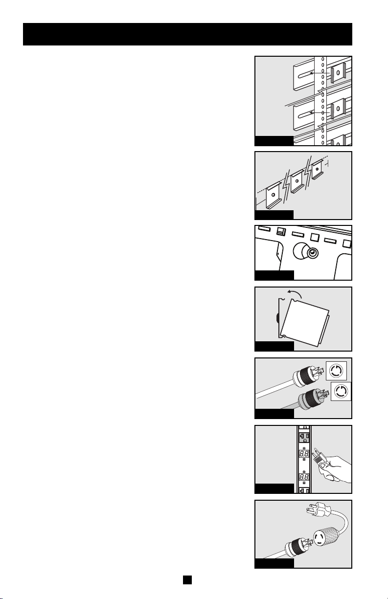
STEP 1A - Zero U Rack Configuration. Attach the three
mounting clips supplied with the PDU to the rack enclosure
using the included hardware. The mounting clips should be
attached along a vertical plane at equidistant points which
roughly correspond to the center and ends of the PDU. The
exact mounting configuration may vary depending on the rack
and enclosure. If possible, use pre-existing mounting points
within the enclosure.
STEP 1B - Wall or Under-Counter Configuration. Attach
the three mounting clips supplied with the PDU to a wall or
similar flat, secure surface using the included hardware. The
mounting clips should be attached along a vertical or
horizontal plane at equidistant points which roughly
correspond to the center and ends of the PDU. If possible, use
pre-existing mounting points. WARNING: Do not attempt
to mount the PDU with the outlets facing downward; the
mounting clips are not designed to support the weight of
the PDU in that manner.
STEP 1C - Zero U Rack Configuration (Mounting Buttons).
Attach the included mounting buttons to the PDU. Position the
PDU as desired in the rack enclosure, align the buttons with the
rack mounting slots, and slide the PDU into position.
Note: Regardless of configuration, the user must determine
the fitness of hardware and procedures before mounting. The
PDU and included hardware are designed for common rack
and rack enclosure types and may not be appropriate for all
applications.
STEP 2: Attach the PDU to the mounting clips. Using an
assistant, place a rear corner of the PDU at an inside edge of
the mounting clips, pivot the PDU toward the alternate inside
edge and snap into place.
STEP 3: Attach each input plug of the PDU to a grounded
outlet. The input plugs, power cords, breakers and outlets are
color-coded to correspond to the two independent power
circuits. WARNING: Attach each input plug to a separate
power circuit. Consult with the electrician at the
installation site if necessary.
STEP 4: Attach equipment to the PDU. Do not exceed the
load rating for each circuit; distribute equipment appropriately
between the two circuits to obtain the maximum utility from
the PDU. The total electrical current used by each circuit will
be displayed on the corresponding digital meter in amperes.
The meter labels are color-coded to match the circuits.
STEP 5: Optional Installation. The PDU includes two
adapters that convert the L5-20P input plugs to 5-20P input
plugs. Use both adapters, a single adapter or neither of the
adapters. The adapters are optional; the PDU will work
properly without connecting the adapters. The adapters are not
color-coded.
2
Step 1A
Step 1B
Step 1C
Step 2
Step 3
Step 4
Step 5
Page 3

Features
1 2 3 4
NEMA L5-20P Input Plugs: The input plugs and associated power cords are
1
5
color-coded to correspond with each of the independent power circuits.
NEMA 5-20P Plug Adapters: The adapters convert the input plugs from NEMA
2
L5-20P to NEMA 5-20P. The adapters are not color-coded.
Circuit Breakers: If the current drawn by the equipment connected to the corresponding
3
independent power circuit exceeds that circuit’s Maximum Load Rating, a circuit breaker
will trip to prevent possible damage. When a circuit breaker trips, its plunger will pop up.
Disconnect excess equipment from the affected circuit and allow the breaker to cool one
minute before depressing the plunger to reset the breaker. The circuit breakers are colorcoded to correspond with each of the independent power circuits.
NEMA 5-15/20R Outlets: The outlets are color-coded to correspond with each of the
4
independent power circuits.
5
Ammeters: The total electrical current used by each circuit will be displayed on the
corresponding digital meter in amperes. The meter labels are color-coded to match the
circuits.
Warranty & Warranty Registration
LIMITED LIFETIME WARRANTY
Seller warrants this product, if used in accordance with all applicable instructions, to be free from original defects in material and workmanship for its lifetime.
If the product should prove defective in material or workmanship within that period, Seller will repair or replace the product, at its sole discretion. Service
under this Warranty can only be obtained by Buyer delivering or shipping the product (with all shipping or delivery charges prepaid) to: Tripp Lite, 1111 W.
35th Street, Chicago, IL 60609. Seller will pay return shipping charges. Call Tripp Lite at (773) 869-1234 before sending any equipment back for repair.
THIS WARRANTY DOES NOT APPLY TO NORMAL WEAR OR TO DAMAGE RESULTING FROM ACCIDENT, MISUSE, ABUSE OR NEGLECT. SELLER
MAKES NO EXPRESS WARRANTIES OTHER THAN THE WARRANTY EXPRESSLY SET FORTH HEREIN. EXCEPT TO THE EXTENT PROHIBITED
BY APPLICABLE LAW, ALL IMPLIED WARRANTIES, INCLUDING ALL WARRANTIES OF MERCHANTABILITY OR FITNESS, ARE LIMITED IN
DURATION TO THE WARRANTY PERIOD SET FORTH ABOVE; THIS WARRANTY EXPRESSLY EXCLUDES ALL INCIDENTALAND CONSEQUENTIAL
DAMAGES. (Some states do not allow limitations on how long an implied warranty lasts, and some states do not allow the exclusion or limitation of
incidental or consequential damages, so the above limitations or exclusions may not apply to you. This Warranty gives you specific legal rights, and you
may have other rights which vary from jurisdiction to jurisdiction).
WARNING: The individual user should take care to determine prior to use whether this device is suitable, adequate or safe for the use intended. Since
individual applications are subject to great variation, the manufacturer makes no representation or warranty as to the suitability or fitness of these devices
for any specific application.
WARRANTY REGISTRATION
Visit www.tripplite.com/warranty today to register the warranty for your new Tripp Lite product. You'll be automatically entered into a drawing for a chance
to win a FREE Tripp Lite product!*
* No purchase necessary. Void where prohibited. Some restrictions apply. See website for details.
Regulatory Compliance Identification Numbers
For the purpose of regulatory compliance certifications and identification, your Tripp Lite product has been assigned a unique series number. The series
number can be found on the product nameplate label, along with all required approval markings and information. When requesting compliance information
for this product, always refer to the series number. The series number should not be confused with the marking name or model number of the product.
The policy of Tripp Lite is one of continuous improvement. Specifications are subject to change without notice.
Made in China.
3
 Loading...