

Page 1

Warranty
Registration
Register online today for a
chance to win a FREE Tripp Lite
product! www.tripplite.com/warranty
Owner’s Manual
Monitored Rack PDU
Switched Rack PDU
Zero U (Vertical) Format
AG-0008 (120V 12A Models) • AG-0009 (120V 16A Models) • AG-0010 (120V 24A Models)
Important Safety Instructions 2
Monitored Rack PDU Features 2
Switched Rack PDU Features 2
Installation 3
Features 8
Configuration and Operation 10
Warranty and Warranty Registration 11
Español 13
Français 25
1111 W. 35th Street • Chicago, IL 60609 USA
201112142 933151.indb 1 1/24/2012 2:09:50 PM
www.tripplite.com/support
Copyright © 2012 Tripp Lite. All rights reserved.
1
Page 2

Important Safety Instructions
SAVE THESE INSTRUCTIONS
This manual contains instructions and warnings that should be followed
during the installation, operation, and storage of this product. Failure to
heed these instructions and warnings will void the product warranty.
• The PDU provides convenient multiple outlets, but it DOES NOT provide surge or line noise
protection for connected equipment.
• The PDU is designed for indoor use only in a controlled environment isolated from excess
moisture, temperature extremes, conductive contaminants, dust or direct sunlight.
• Do not connect the PDU to an ungrounded outlet or to extension cords or adapters that
eliminate the connection to ground.
• The power requirement for each item of equipment connected to the PDU must not exceed
the individual outlet’s load rating.
• The total power requirement for equipment connected to the PDU must not exceed the
maximum load rating for the PDU.
• Do not drill into or attempt to open any part of the PDU housing. There are no userserviceable parts inside.
• Do not attempt to modify the PDU, including its input plugs and power cables.
• Do not attempt to use the PDU if any part of it is damaged.
• Do not attempt to mount the PDU to an insecure or unstable surface.
• Never attempt to install electrical equipment during a thunderstorm.
• Use of this equipment in life support applications where failure of this equipment can
reasonably be expected to cause the failure of the life support equipment or to significantly
affect its safety or effectiveness is not recommended. Do not use this equipment in the
presence of a flammable anesthetic mixture with air, oxygen or nitrous oxide.
Monitored Rack PDU Features
• Network interface enables remote power monitoring and event notification
• Digital amp meter for on-site load monitoring
• Centralized management of hundreds of PDUs and environmental sensors with Tripp Lite’s
free PowerAlert Network Management System
• Optional ENVIROSENSE accessory allows monitoring of network ambient temperature,
humidity and up to three dry contacts
• Toolless button-mount installation in Tripp Lite SmartRack™ and many third-party enclosures
Switched Rack PDU Features
• Network interface enables remote power monitoring and individual outlet control
• Individually controllable outlets allow remote rebooting of locked-up network devices
• Digital amp meter for on-site load monitoring
• Centralized management of hundreds of PDUs and environmental sensors with Tripp Lite’s
free PowerAlert Network Management System
• Optional ENVIROSENSE accessory allows monitoring of network ambient temperature,
humidity and up to three dry contacts
• Toolless button-mount installation in Tripp Lite SmartRack and many third-party enclosures
2
201112142 933151.indb 2 1/24/2012 2:09:50 PM
Page 3
Installation
Mounting the PDU
Note: The illustrations may differ somewhat from your PDU model. Regardless of configuration, the user must
determine the fitness of hardware and procedures before mounting. The PDU and included hardware are
designed for common rack and rack enclosure types and may not be appropriate for all applications. Exact
mounting configurations may vary. Screws for attaching the mounting brackets and cord retention shelf to the
PDU are included. Use only the screws supplied by the manufacturer, or their exact equivalent (#6-32, ¼"
flat head).
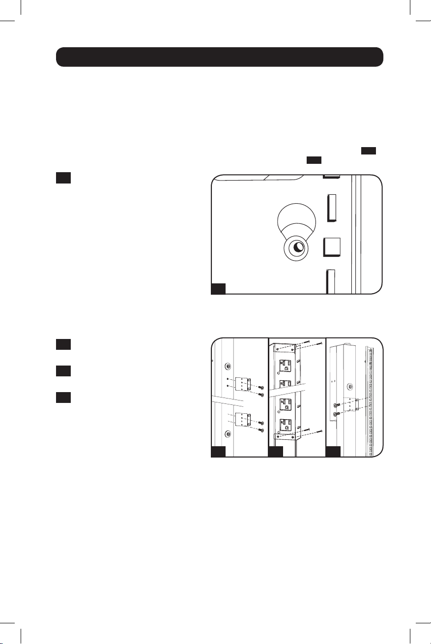
If installing the PDU in a rack that has button-mount slots, you only need to perform step
If your rack enclosure does not have button-mount slots, proceed to step
1-1
To install the PDU in a rack equipped
1-2
.
with button-mount slots, insert the
mounting buttons on the rear of the
PDU into the button-mount slots on
the rack and slide the PDU down until
the mounting buttons engage the
narrow section of the of the buttonmount slots.
Note: To install the PDU with its outlets
facing the rear of the rack, use the
included PDUMVROTATEBRKT accessory.
This V-shaped bracket provides a mounting
button on one leg of the V and a buttonmount slot on the other, effectively
repositioning the mounting buttons. See
Features section for image.
1-1
1-1
.
1-2
Attach the mounting brackets to the
PDU.
1-3
(Optional) Attach the cord retention
bracket(s) to the PDU.
1-4
Attach the PDU to a vertical rail in
your rack or rack enclosure. (Use the
mounting hardware that came with
your rack or rack enclosure to attach
the mounting brackets to the rail.)
1-2
1-3 1-4
3
201112142 933151.indb 3 1/24/2012 2:09:51 PM
Page 4
Installation continued
Connecting the PDU
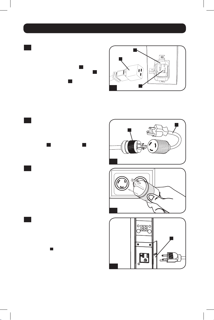
2-1
(Models with IEC power inlet or 3-pole
IEC 309 plug only.) Select models have
a detachable power cord. Attach the
included power cord to the PDU by
inserting the IEC connector A of the
power cord into the IEC power inlet B
located near the end of the PDU. Use
the included bracket C to secure the
power cord connection.
Note: Optionally, a user-supplied power cord
can be attached to the PDU by connecting it
to the IEC inlet. Do not attempt to attach a
user-supplied power cord unless it is certified
to be compatible with the input power source
that will be used by the PDU.
2-2
(Optional - models with input plug
adapter only.) Select models include an
input plug adapter that converts the
twist-lock input plug to a straight-blade
input plug. Attach the input plug
adapter A to the input plug B if you
wish to plug the PDU into a compatible
straight-blade outlet.
2-3
Connect the input plug to a compatible
AC power outlet. If the PDU does not
have a circuit breaker, it should be
provided with a branch-rated overcurrent protection device that matches
the rated amperage of the PDU.
Note: The AC power source should not share
a circuit with a heavy electrical load.
2-1
2-2
2-3
C
A
B
A
B
2-4
(Optional) If you attached the cord
retention bracket(s), tie each
equipment power cord to the retention
bracket. Attach each cord to the
retention shelf by looping the cord and
A
securing it with one of the included
cable ties A. Make sure that each cord
can be unplugged from the PDU without
removing the cable tie.
2-4
4
201112142 933151.indb 4 1/24/2012 2:09:52 PM
Page 5
CONFIGCONFIGACCYACCY
LINKLINK
STATUSSTATUS
12
11 10 9 8 7
6 5 4 3
Installation continued
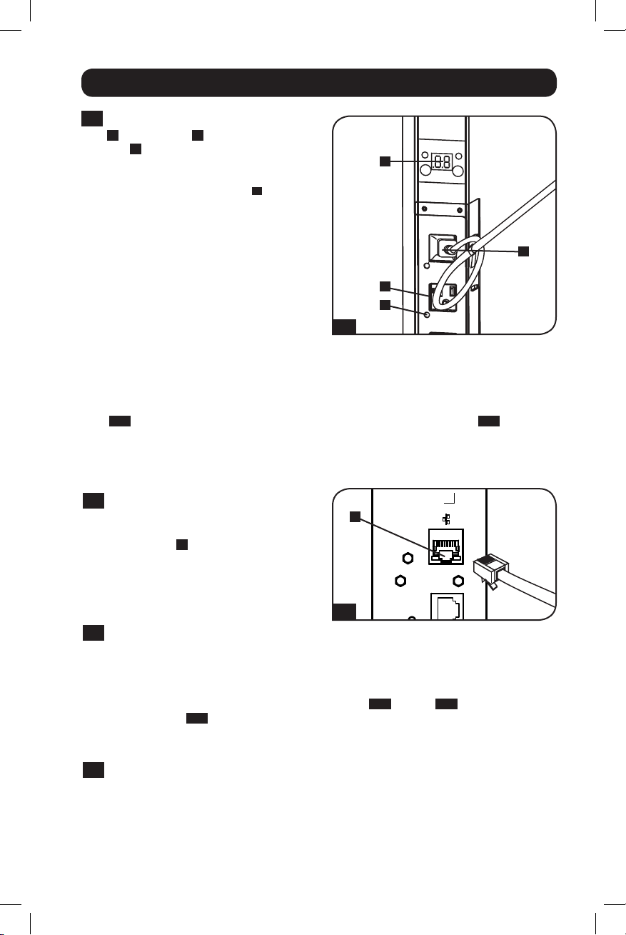
2-5
Connect your equipment's input plugs
A
to the outlets B of the PDU. The
LED C near each outlet (Switched
Models Only) illuminates when the
outlet is ready to distribute live AC
power. The digital load meter D displays
the total connected equipment load in
amps. (Select models provide additional
load data. See the Features section
for more information.)
Note: In order to minimize interference among
connected devices, connect each device to
the nearest PDU outlet and coil excess power
cord length.
2-5
Networking the PDU
Note: The MAC address of the PDU (a 12-digit string in this format: 000667xxxxxx) is printed on a label
attached to the PDU enclosure.
If your network's DHCP server will assign a dynamic IP address to the PDU automatically, go to
3-1
Step
uncertain which method to use, contact your network administrator for assistance before
continuing the installation process.
. If you will assign a static IP address to the PDU manually, go to Step
D
A
B
C
4-1
. If you are
Dynamic IP Address Assignment
3-1
Connect PDU to Network: While the
PDU is powered, connect a standard
Ethernet patch cable to the RJ-45
Ethernet port A on the PDU.
Note: This port is not compatible with PoE
(Power over Ethernet) applications. The PDU
will attempt to obtain an IP address via DHCP.
This may take as long as several minutes,
depending on your network environment.
3-2
Discover IP Address: Contact your network administrator to determine which dynamic IP
address has been assigned to the PDU by the DHCP server. The PDU can be identified on
the DHCP server by referring to its MAC address. (The MAC address is a 12-digit string in
this format: 000667xxxxxx. Refer to the MAC address label attached to the PDU.) You may
wish to request a long-term lease period for the IP address, depending on your application.
After you have discovered the IP address, skip Steps
directly to Step
5-1
.
Static IP Address Assignment
4-1
Determine IP Information: Before assigning a static IP address, you'll need to know the
IP address, gateway address and subnet mask. If you do not have this information, contact
your network administrator for assistance.
A
3-1
4-1
through
4-6
and proceed
5
201112142 933151.indb 5 1/24/2012 2:09:54 PM
Page 6
Installation continued
ENVIROSENSEENVIROSENSE
CONFIGCONFIGACCYACCY
RESETRESET
LINKLINK
STATUSSTATUS
12
11 10 9 8 7
6 5 4 3
4-2
Configure Terminal Emulation Program: Open a VT100-compatible terminal emulation
program (such as the HyperTerminal program bundled with Microsoft® Windows®) on a
computer with an available DB9 serial port. (A notebook computer may be the most
convenient choice.) Set the terminal emulation program to use the COM port that
corresponds to the computer’s DB9 serial port. Specify the parameters required to
communicate with the PDU terminal interface:
Bits per second: 9600
Data bits: 8
Parity: None
If the terminal emulation program supports multiple emulation modes, you may also need
to specify VT100 emulation.
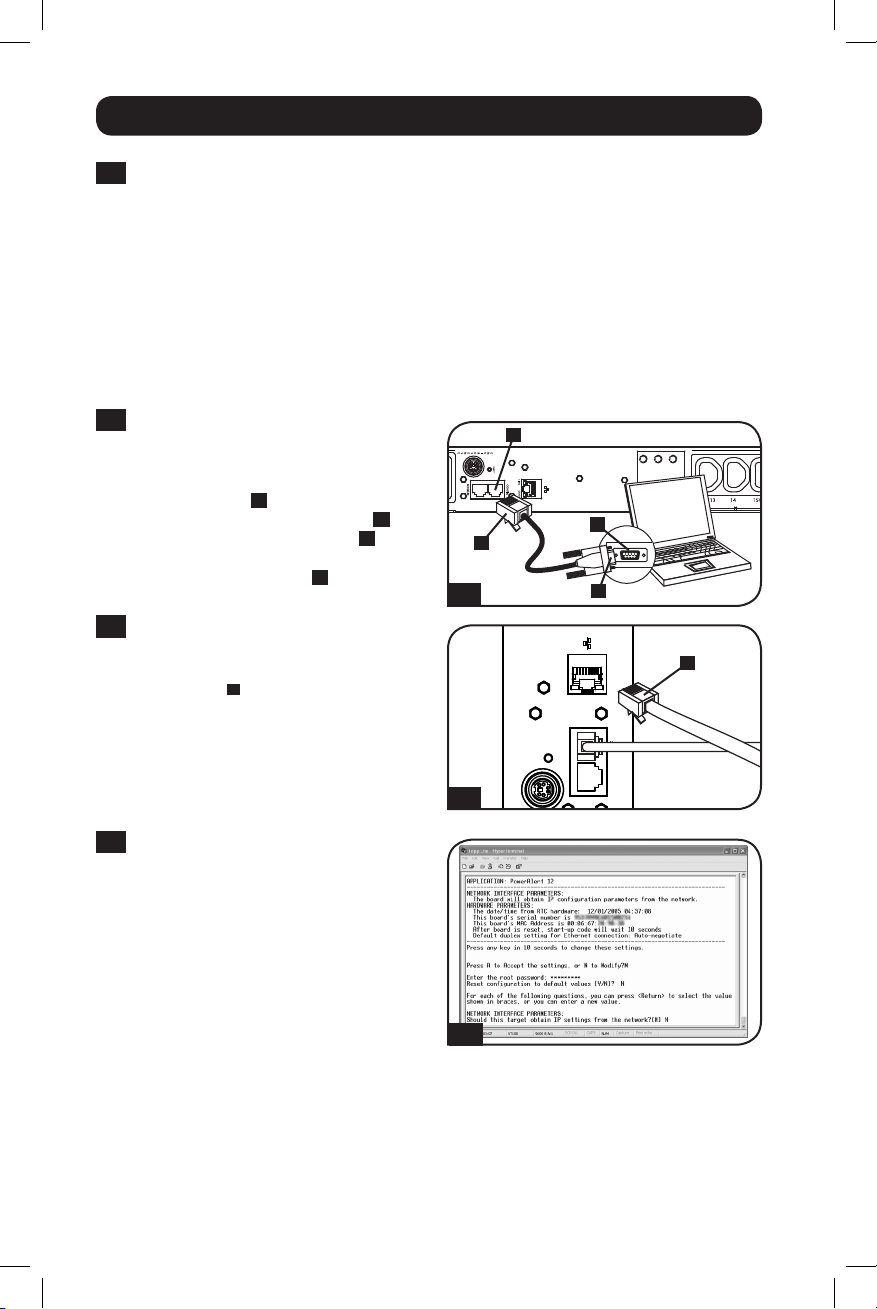
4-3
Connect PDU to Computer: Use the
RJ-45 to DB9 serial cable (part number
73-1243) included with the PDU to
connect the PDU to the computer. The
RJ-45 connector A at one end of the
cable attaches to the CONFIG port B
on the PDU. The DB9 connector C at
the other end of the cable connects to
the computer's serial port D.
4-4
Connect PDU to Network: While the
PDU is powered, connect a standard
Ethernet patch cable to the RJ-45
Ethernet port A on the PDU.
Note: This port is not compatible with PoE
(Power over Ethernet) applications.
Stop bits: 1
Flow control: None
B
A
4-3
D
C
A
4-4
4-5
Configure PDU in Terminal Mode:
After a brief pause, an initialization page
should appear in the terminal emulation
program. Press any key on the keyboard
within 10 seconds to change the PDU
settings. (If the 10-second period has
elapsed, you can reboot the PDU by
pressing the SNMP reset switch.)
Follow the sequence of responses below
in order to assign an IP address to the
PDU. The default terminal mode root
4-5
password is TrippLite. Sample IP settings
are shown - supply your own IP
information when you configure your
PDU.
6
201112142 933151.indb 6 1/24/2012 2:09:55 PM
Page 7
Installation continued
Press A to Accept the settings, or M to Modify? M
Enter the root password: *********
Reset configuration to default values (Y/N)? N
For each of the following questions, you can press <Return> to select the value shown in
braces, or you can enter a new value.
NETWORK INTERFACE PARAMETERS:
Should this target obtain IP settings from the network?[N] N
Static IP address [192.168.1.19]? 192.168.0.123
Static IP address is 192.168.0.123
Subnet Mask IP address [255.255.0.0]? 255.255.255.0
Subnet Mask IP address is 255.255.255.0
Gateway address IP address [192.168.1.1]? 192.168.0.1
Gateway address IP address is 192.168.0.1
You can also change the root password, real-time clock and other settings. (Tripp Lite
recommends against changing the default settings unless you are an advanced user with a
specific purpose.) After you have finished entering settings, the PDU will save changes to memory
and reboot (this may take several minutes). After the PDU reboots, the initialization page should
display the new static IP settings.
4-6
Remove Serial Cable: Remove the serial cable from the PDU and proceed to Step
Testing Network Connection
5-1
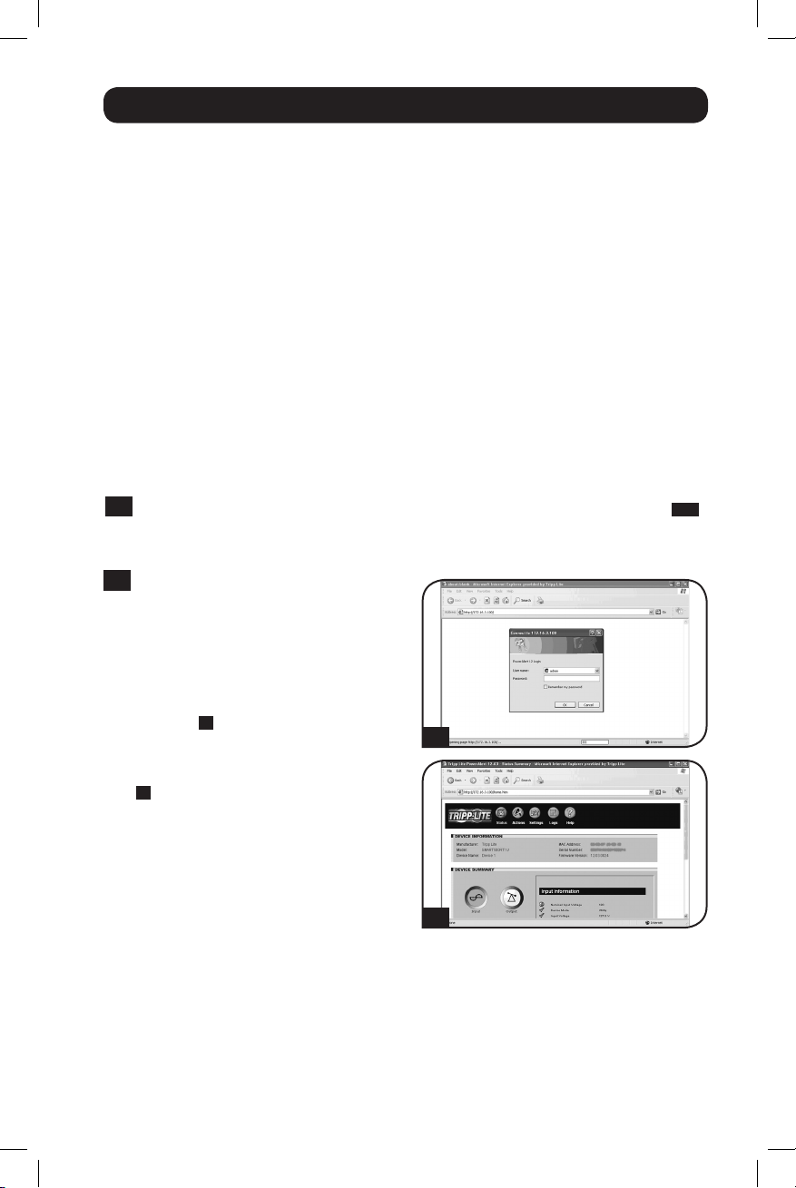
Access PDU with Web Browser:
After an IP address has been assigned
to the PDU, attempt to access it with a
Web browser that supports frames,
forms and Java™. Open a Web browser
on a computer connected to the LAN
and enter the IP address assigned to
the PDU. You should be prompted for a
password A. The user name is admin
and the default password is admin.
After you enter the user name and
password, the PowerAlert status page
B
will appear in the browser window.
For more information about
configuration and operation of the PDU
via the PowerAlert interface, refer to the
SNMPWEBCARD User's Guide, included
on the CD-ROM bundled with the PDU.
Note for Network Management System Users
Only: Two MIB files - Tripplite.mib and
RFC1628.mib - must be loaded on each
Network Management Station that will
monitor the PDU via SNMP. The files are
provided on the CD-ROM included in the
product package.
A
B
5-1
.
7
201112142 933151.indb 7 1/24/2012 2:09:56 PM
Page 8
Features
E
D
A
C
E
Bank1
Scroll
IP
.8.8
LOAD(AMPS)
LOAD(AMPS)
Select/
Rotate
Bank2
30 Amp 20 Amp
ScrollIP/
Rotate
LOAD (AMPS)LOAD(AMPS)
.8.8
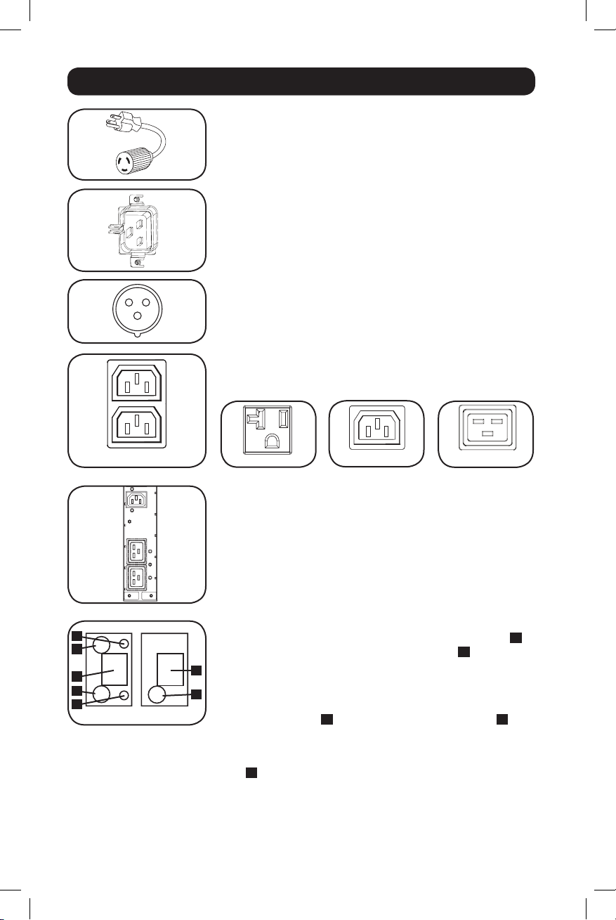
Input Plug Adapter (Select Models): Converts the PDU's
twist-lock input plug to a straight-blade input plug.
Power Inlet (Select Models): The IEC power inlet connects to
the included power cord or a compatible user-supplied power
cord. The inlet includes a bracket to secure the cord connection.
IEC 309 3-Pole Input Plug: Available on select models.
Outlets (Vary by Model): During normal operation, the outlets
distribute AC power to connected equipment. Select models
feature an LED that indicates outlet status.
IEC-60320-C132-Position IEC-60320-C13 IEC-60320-C19NEMA 5-15/20R
Outlet LEDs: On switched models, each outlet LED illuminates
w h e n t h e a s s o c i a t e d o u t l e t i s r e a d y t o d i s t r i b u t e l i v e A C p o w e r .
Digital Load Meter (Ammeter): The total connected
equipment load in amperes is displayed by the digital meter A.
20-amp models feature a Scroll IP/Rotate Switch B. Press this
switch for one second to display the PDU’s IP address (two
A
LOAD (AMPS)LOAD(AMPS)
characters at a time). Press for two seconds to rotate the LED
display for ease of reading in vertical installations with the input
B
cord at the top or bottom of the PDU. 30-amp models feature a
Select/Rotate Switch C and a dedicated Scroll IP Switch D.
Press the Select/Rotate Switch once to display the total load (in
amps) on the PDU. Press again to display the load on Bank 1 of
the PDU and again to display the load on Bank 2. The Load Bank
LEDs E will indicate display status as follows. Both outlet bank
LEDs illuminated: total PDU load displayed. Bank 1 or Bank 2
LED illuminated: load on corresponding load bank displayed.
Press the Select/Rotate Switch for two seconds to rotate the LED
display for ease of reading in vertical installations with the input
cord at the top or bottom of the PDU.
8
201112142 933151.indb 8 1/24/2012 2:09:57 PM
Page 9
Features continued
12
11 10 9 8 7
6 5 4 3
2 1
Circuit Breakers (Select Models): If the connected
equipment load on a load bank exceeds the Maximum Load
Rating of the load bank, the circuit breaker will trip. Disconnect
excess equipment and switch breaker to the on position to reset
the breaker. Models with multiple outlet banks have a circuit
breaker for each bank. Circuit breakers are only used to protect
output load banks.
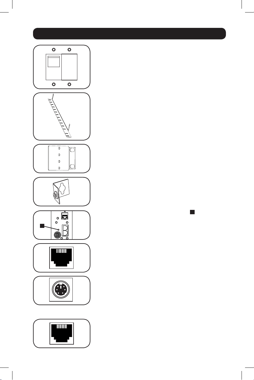
Cord Retention Bracket: Provides secure attachment points
for connected equipment cords.
Mounting Brackets: Use these brackets to mount the PDU.
PDUMVROTATEBRKT Mounting Accessory: Use these
V-shaped brackets to mount the PDU with its outlets facing the
rear of the rack.
SNMP Reset Button: Press the reset button A for 3 seconds
LINKLINK
STATUSSTATUS
A
CONFIGCONFIGACCYACCY
RESETRESET
ENVIROSENSEENVIROSENSE
to reboot the PDU's network card. Rebooting the network card
will not erase network settings or interrupt AC power. The reset
button is recessed; use a suitable tool to press it.
ACCY Port: The port is reserved for future expansion.
PS/2 Port: Use this port to connect a Tripp Lite ENVIROSENSE
environmental sensor to provide remote temperature/humidity
monitoring and a dry contact interface to control and monitor
alarm, security and telecom devices. Visit www.tripplite.com for
ordering information. Note: Do not connect a keyboard or mouse
to this port.
RJ-45 Configuration Port: Use this port to provide a direct
terminal connection to a computer with a terminal emulation
program. An RJ-45 cable is included with the PDU. If you need a
replacement cable, visit www.tripplite.com for ordering
information.
9
201112142 933151.indb 9 1/24/2012 2:09:59 PM
Page 10
Features continued
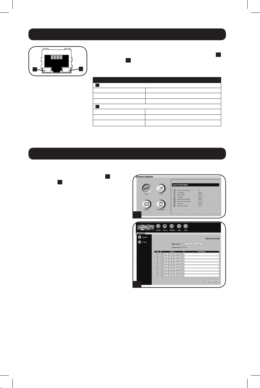
Ethernet Port: Use this RJ-45 jack to connect the PDU to the
network with a standard Ethernet patch cable. The Link LED A
and Status LED B indicate several operating conditions, as
shown in the table below. This port is not compatible with PoE
A
B
(Power Over Ethernet) applications.
A
Link LED Color
Off No Network Connection
Flashing Amber 100 Mbps Network Connection
Flashing Green 10 Mbps Network Connection
B
Status LED Color
Off Card Not Initialized
Steady Green Card Initialized and Operational
Flashing Amber Error - Card Not Initialized
Configuration and Operation
Remote Monitoring and Control
The PDU provides remote monitoring A,
outlet control B and more via Web browser,
telnet and SNMP-based Network
Management Systems. For more information
about configuration and operation of the
PDU via the PowerAlert Web browser
interface, refer to the SNMPWEBCARD User's
Guide, included on the CD-ROM bundled
with the PDU.
Network Operating Conditions
A
B
10
201112142 933151.indb 10 1/24/2012 2:09:59 PM
Page 11

Warranty and Warranty Registration
LIMITED WARRANTY
Seller warrants this product, if used in accordance with all applicable instructions, to be free from original
defects in material and workmanship for a period of 2 years (except internal UPS system batteries outside USA
and Canada, 1 year) from the date of initial purchase. If the product should prove defective in material or
workmanship within that period, Seller will repair or replace the product, in its sole discretion. Service under this
Warranty can only be obtained by your delivering or shipping the product (with all shipping or delivery charges
prepaid) to: Tripp Lite, 1111 W. 35th Street, Chicago, IL 60609 USA. Seller will pay return shipping charges.
Visit www.tripplite.com/support before sending any equipment back for repair.
THIS WARRANTY DOES NOT APPLY TO NORMAL WEAR OR TO DAMAGE RESULTING FROM ACCIDENT, MISUSE,
ABUSE OR NEGLECT. SELLER MAKES NO EXPRESS WARRANTIES OTHER THAN THE WARRANTY EXPRESSLY SET
FORTH HEREIN. EXCEPT TO THE EXTENT PROHIBITED BY APPLICABLE LAW, ALL IMPLIED WARRANTIES,
INCLUDING ALL WARRANTIES OF MERCHANTABILITY OR FITNESS, ARE LIMITED IN DURATION TO THE
WARRANTY PERIOD SET FORTH ABOVE; AND THIS WARRANTY EXPRESSLY EXCLUDES ALL INCIDENTAL AND
CONSEQUENTIAL DAMAGES. (Some states do not allow limitations on how long an implied warranty lasts, and
some states do not allow the exclusion or limitation of incidental or consequential damages, so the above
limitations or exclusions may not apply to you. This Warranty gives you specific legal rights, and you may have
other rights which vary from jurisdiction to jurisdiction).
WARNING: The individual user should take care to determine prior to use whether this device is suitable,
adequate or safe for the use intended. Since individual applications are subject to great variation, the
manufacturer makes no representation or warranty as to the suitability or fitness of these devices for any specific
application.
WARRANTY REGISTRATION
Visit www.tripplite.com/warranty today to register the warranty for your new Tripp Lite product. You'll be
automatically entered into a drawing for a chance to win a FREE Tripp Lite product!*
* No purchase necessary. Void where prohibited. Some restrictions apply. See website for details.
FCC Notice
This device complies with part 15 of the FCC Rules. Operation is subject to the following two conditions: (1) This
device may not cause harmful interference, and (2) this device must accept any interference received, including
interference that may cause undesired operation.
This equipment has been tested and found to comply with the limits for a Class A digital device, pursuant to
part 15 of the FCC Rules. These limits are designed to provide reasonable protection against harmful
interference when the equipment is operated in a commercial environment. This equipment generates, uses,
and can radiate radio frequency energy and, if not installed and used in accordance with the instruction manual,
may cause harmful interference to radio communications. Operation of this equipment in a residential area is
likely to cause harmful interference in which case the user will be required to correct the interference at his own
expense. The user must use shielded cables and connectors with this product. Any changes or modifications to
this product not expressly approved by the party responsible for compliance could void the user's authority to
operate the equipment.
Regulatory Compliance Identification Numbers
For the purpose of regulatory compliance certifications and identification, your Tripp Lite product has been
assigned a unique series number. The series number can be found on the product nameplate label, along with
all required approval markings and information. When requesting compliance information for this product,
always refer to the series number. The series number should not be confused with the marking name or model
number of the product.
Tripp Lite follows a policy of continuous improvement. Specifications are subject to change without notice.
11
201112142 933151.indb 11 1/24/2012 2:09:59 PM
Page 12

1111 W. 35th Street • Chicago, IL 60609 USA
www.tripplite.com/support
201112142 933151-EN
12
201112142 933151.indb 12 1/24/2012 2:09:59 PM
Page 13

Manual del propietario
PDU Monitoreada para Rack
PDU Switched para Rack
Cero U (Vertical) Formato en Barra
AG-0008 (Modelos 120V 12A) • AG-0009 (Modelos 120V 16A)
Instrucciones de seguridad importantes 14
Características de la PDU monitoreada para Rack 14
Características alternas de la PDU para Rack 14
Instalación 15
Características 20
Configuración y operación 23
Garantía 24
English 1
Français 25
AG-0010 (Modelos 120V 24A)
1111 W. 35th Street • Chicago, IL 60609 USA
© 2012 Tripp Lite. Todos los derechos reservados.
201112142 933151.indb 13 1/24/2012 2:10:00 PM
www.tripplite.com/support
13
Page 14

Instrucciones de seguridad importantes
GUARDE ESTAS INSTRUCCIONES
Este manual contiene instrucciones y advertencias que deben seguirse
durante la instalación, operación y almacenamiento de este producto.
De no seguirlas, se anulará la garantía del producto.
• El PDU proporciona cómodas salidas múltiples, pero NO proporciona protección contra
sobretensión o ruido en la línea al equipo conectado.
• El PDU está diseñada sólo para empleo en interiores en un ambiente controlado, lejos del exceso
de humedad, temperaturas extremas, contaminantes conductores, polvo o luz solar directa.
• No conecte el PDU a una salida sin conexión a tierra ni a cables de extensión o adaptadores
que eliminen la conexión a tierra.
• El requisito de potencia de cada equipo conectado a1 PDU no debe exceder la capacidad de
carga individual de la salida.
• El requisito de potencia total para el equipo conectado el PDU no debe exceder la máxima
capacidad de carga para el PDU.
• No taladre ni trate de abrir ninguna parte de la cubierta del PDU. No hay partes en su interior
que requieran mantenimiento por parte del usuario.
• No intente modificar el PDU, incluyendo los enchufes de entrada y los cables de alimentación.
• No intente usar el PDU si alguno de sus componentes está dañado.
• No intente montar el PDU en una superficie insegura o inestable.
• Nunca intente instalar equipos eléctricos durante una tormenta eléctrica.
• El uso de este equipo en aplicaciones de soporte de vida en donde la falla de este equipo
pueda razonablemente hacer suponer que causará fallas en el equipo de soporte de vida o
afecte significativamente su seguridad o efectividad, no está recomendado. No use este
equipo en la presencia de una mezcla anestésica inflamable con aire, oxigeno u óxido nitroso.
Características de la PDU Monitoreada para Rack
• La interfaz de red permite el monitoreo remoto de energía y la notificación del suceso
• Medidor digital en amperios para el monitoreo de la carga en el sitio
• Administración centralizada de cientos de sensores ambientales de las PDUs, con el Sistema
de Administración de Redes PowerAlert gratuito de Tripp Lite
• Accesorio opcional ENVIROSENSE que permite el monitoreo de la temperatura ambiente, la
humedad y hasta tres contactos secos de la red
• Instalación sin herramientas con montaje por botones en gabinetes Tripp Lite SmartRack™ y
muchos otros de terceros
Características alternas de la PDU para Rack
• La interfaz de red permite el monitoreo remoto de la energía y el control individual del
tomacorriente
• Los tomacorrientes controlables individualmente permiten el reinicio remoto de los
dispositivos de red bloqueados
• Medidor digital en amperios para monitoreo de la carga en el sitio
• Administración centralizada de cientos de PDUs y sensores ambientales con el Sistema de
Administración de Red PowerAlert gratuito de Tripp Lite
• Accesorio ENVIROSENSE que permite el monitoreo de la temperatura ambiente, la humedad
y hasta tres contactos secos de la red
• Instalación sin herramientas con montaje por botones en gabinetes Tripp Lite SmartRack™ y
muchos otros de terceros
201112142 933151.indb 14 1/24/2012 2:10:00 PM
14
Page 15

Instalación
Montaje del PDU
Nota: Las ilustraciones pueden ser un poco diferentes a las de su modelo de PDU. Independientemente de la
configuración, el usuario debe determinar la idoneidad de los materiales y accesorios así como de los
procedimientos antes del montaje. El PDU y el material incluido están diseñados para racks (bastidores) y
cajas de rack (bastidor) comunes, y pueden no ser apropiados para todas las aplicaciones. Se incluyen los
tornillos para fijar los soportes de montaje y la repisa para el retención de cables al PDU. Use únicamente los
tornillos suministrados por el fabricante o su equivalente exacto (#6-32, ¼" de cabeza plana).
Si instala la PDU en un rack que tiene ranuras de montaje de botón, solo necesita realizar el
1-1
paso
1-1
. Si su rack no tiene ranuras de montaje de botón, proceda con el paso
Para instalar la PDU en un rack
equipado con ranuras de montaje de
botón, inserte los botones de montaje
en la parte trasera de la PDU dentro de
las ranuras de montaje de botón sobre
el rack, y deslice la PDU hacia abajo
hasta que los botones de montaje
enganchen en la sección estrecha de
las ranuras de montaje de botón.
Para instalar la PDU en un rack equipado
con ranuras de montaje de botón, inserte
los botones de montaje en la parte trasera
de la PDU dentro de las ranuras de
montaje de botón sobre el rack, y deslice la
PDU hacia abajo hasta que los botones de
montaje enganchen en la sección estrecha
de las ranuras de montaje de botón.
1-2
Fije los soportes de montaje al PDU.
1-3
(Opcional) Fije la(s) abrazaderas(s)
de retención del cable al PDU.
1-4
Fije el PDU a un riel vertical en su
rack o estante para rack. (Use las
piezas de montaje que vienen con su
rack o estante para rack para fijar los
soportes de montaje al riel.)
1-1
1-2
.
1-2
1-3 1-4
15
201112142 933151.indb 15 1/24/2012 2:10:00 PM
Page 16

Instalación continuación
Conexión del PDU
2-1
(Únicamente modelos con una entrada
de corriente IEC o enchufe de entrada
de 3 polos IEC 309.) Modelos selectos
tienen un cable de alimentación
desprendible. Fije el cable de
alimentación, incluido, al PDU
insertando el conector IEC A del cable
de alimentación en la entrada de
corriente IEC B localizada cerca del
extremo del PDU. Use las abrazaderas
incluidas C para asegurar la conexión
del cable de alimentación.
Nota: Opcionalmente, un cable de alimentación,
suministrado por el usuario puede fijarse al PDU
conectándolo a la entrada IEC. No intente
conectar un cable suministrado por el usuario a
menos que esté certificado como compatible
con la fuente de energía de entrada que será
usada con el PDU.
2-2
(Opcional - únicamente modelos con
adaptador de clavija.) Modelos selectos
incluyen un adaptador de clavija de
entrada que convierte la clavija de
entrada de media vuelta a una clavija
de entrada de pala recta. Conecte el
adaptador de la clavija de entrada A a
la clavija de entrada B si desea
enchufar el PDU a una toma de
corriente de pala recta compatible.
2-3
Conecte la clavija de entrada a una
toma de corriente CA compatible. Si el
PDU no tiene un interruptor de circuitos,
debe colocársele un dispositivo de
protección contra sobre corriente que
tenga el mismo amperaje del PDU.
Nota: La fuente de energía CA no debe
compartir un circuito con una carga eléctrica
grande.
2-4
(Opcional) Si fijo las abrazaderas de
retención del cable, sujete cada cable
de alimentación de cada equipo a la
abrazadera de retención. Sujete cada
cable a la bandeja de retención
enrollando el cable y asegurándolo con
uno de los sujetadores de cable
incluidos A. Asegúrese de que cada
pueda ser desenchufado del PDU sin
quitar el sujetador del cable.
2-1
2-2
2-3
2-4
C
A
B
A
B
A
16
201112142 933151.indb 16 1/24/2012 2:10:01 PM
Page 17

CONFIGCONFIGACCYACCY
LINKLINK
STATUSSTATUS
12
11 10 9 8 7
6 5 4 3
Instalación continuación
2-5
Conecte las clavijas de entrada de su
equipo A a las tomas de corriente B
del PDU. El LED C junto a cada toma
de corriente se iluminará cuando la
toma de corriente esté lista para
distribuir energía CA viva (Únicamente
Modelos Controlables). El lector
digital de carga D muestra la carga total
del equipo conectado en amperes.
(Modelos selectos proporcionan
información adicional. Vea la sección
Características para mayor información.)
Nota: A fin de minimizar la interferencia entre
los dispositivos conectados, conecte cada
dispositivo a la toma de corriente del PDU
más cercana y enrolle el cable excedente.
2-5
Conectando Su PDU a la Red
Nota: La dirección MAC (Media Access Control / Control de Acceso de Medios) del PDU (una serie de
12-dígitos en este formato: 000667xxxxxx) está impresa en una etiqueta adherida al gabinete del PDU.
Si el DHCP (Dynamic Host Configuration Protocol / Protocolo Dinámico de la Configuración del
Anfitrión) de su servidor de red asignará una dirección dinámica al PDU automáticamente, vaya
3-1
al Paso
Si no está seguro que método utilizar contacte a su administrador de red para obtener
asistencia antes de continuar con el proceso de instalación.
Asignación de una Dirección IP Dinámica
3-1
Nota: Este puerto no es compatible con la
3-2
. Si Usted asignará manualmente una dirección estática al PDU vaya al Paso
Conecte el PDU la red: Conecte un
cable patch estándar al puerto Ethernet
RJ-45 A en el PDU.
aplicación PoE (Power over Ethernet /
Energía sobre la Ethernet). El PDU tratará de
obtener una dirección IP a través de DHCP.
Esto puede tomar varios minutos,
dependiendo de su entorno de red.
3-1
Encuentre la Dirección IP: Contacte a su administrador de red para determinar que
Dirección IP ha sido asignada al PDU por el servidor DHCP. El PDU puede ser identificada
en el servidor DHCP refriéndose a su dirección MAC. (La dirección MAC es una serie de
12-dígitos en este formato: 000667xxxxxx. Refiérase a la etiqueta de dirección MAC
adherida al PDU.) Usted puede requerir una asignación por un período prolongado para la
dirección IP, dependiendo de su aplicación. Después de que haya encontrado la dirección
4-1
IP sáltese los Pasos del
4-6
al
y proceda directamente al Paso
D
A
B
C
4-1
A
5-1
.
.
Asignación de una Dirección IP Estática
4-1
Determine la Información IP: Antes de asignar una dirección estática IP, necesita saber
la dirección IP, dirección de entrada y máscara de subnet. Si no tiene esta información,
comuníquese con su administrador de red para obtener asistencia.
201112142 933151.indb 17 1/24/2012 2:10:02 PM
17
Page 18

Instalación continuación
CONFIGCONFIGACCYACCY
RESETRESET
LINKLINK
STATUSSTATUS
12
11 10 9 8 7
6 5 4 3
4-2
Configure el Programa de Emulación Terminal [Terminal Emulation Program]: En
una computadora con un puerto serial DB9 disponible abra un programa de emulación
terminal compatible con VT100 (como el programa HyperTerminal Incluido en Microsoft
Windows®). (Una computadora portátil es la elección más adecuada.) Ajuste el programa
de emulación terminal para usar el puerto COM ese corresponde al puerto serial DB9.
Especifique los valores requeridos para comunicarse con la interfaz de terminal
SNMPWEBCARD:
Bits per second [Bits por segundo]: 9600
Data bits [Bits de datos]: 8
Parity [Paridad]: None [Ninguno]
Si el programa de emulación terminal soporta diversos modos de emulación, necesitará
especificar la emulación VT100.
4-3
Conecte el PDU a la Computadora:
Use el cable serial RJ-45 a DB9 (parte
número 73-1243) incluido con el PDU
para conectar el PDU con la
computadora. Le connecteur RJ-45 A
de uno de los extremos del cable se
une al puerto CONFIG B del PDU.
(Alinee el conector cuidadosamente
para evitar dañar los pines.) El conector
DB9 C el otro extremo del cable se
conecta al puerto serial de la
computadora D.
4-4
Conecte el PDU a la Red: Con el
PDU encendido conecte un cable patch
estándar para Ethernet al puerto
Ethernet RJ-45 A en el PDU.
Nota: Este puerto no es compatible con la
aplicación PoE (Power over Ethernet / Energía
sobre la Ethernet).
Stop bits [bits de parada]: 1
Flow control
[Control de flujo]: None [Ninguno]
B
A
4-3
D
C
A
4-4
®
4-5
Configure el PDU en Modo Terminal:
Después de una breve pausa, una
página de inicialización deberá aparecer
en el programa de emulación terminal.
Presione cualquier tecla en el teclado
antes de 10 segundos para cambiar los
valores del PDU. (Si ya transcurrió el
periodo de 10 segundos, puede reiniciar
la PDU oprimiendo el interruptor de
reinicio SNMP).
4-5
Siga la secuencia de respuesta abajo en
orden para asignar una dirección IP al
PDU. La contraseña de la raíz de fábrica
en modo terminal es TrippLite. Valores
IP de prueba son mostrados -
201112142 933151.indb 18 1/24/2012 2:10:04 PM
proporcione su información IP cuando
configure su PDU.
18
Page 19

Instalación continuación
Press A to Accept the settings, or M to Modify? M
Enter the root password: *********
Reset configuration to default values (Y/N)? N
For each of the following questions, you can press <Return> to select the value shown in
braces, or you can enter a new value.
NETWORK INTERFACE PARAMETERS:
Should this target obtain IP settings from the network?[N] N
Static IP address [192.168.1.19]? 192.168.0.123
Static IP address is 192.168.0.123
Subnet Mask IP address [255.255.0.0]? 255.255.255.0
Subnet Mask IP address is 255.255.255.0
Gateway address IP address [192.168.1.1]? 192.168.0.1
Gateway address IP address is 192.168.0.1
También puede cambiar la contraseña de la Raíz, el reloj-de-tiempo-real, y otros valores.
(Tripp Lite no recomienda cambiar la configuración de fábrica a menos que sea un usuario
avanzado y con objetivos específicos) Después que haya terminado de efectuar los ajustes, el
PDU guardará los cambios en la memoria y se reinicializará (esto puede tomar varios minutos)
Después que el PDU se reinicialice, la página de reincialización deberá desplegar los nuevos
valores estáticos de IP.
4-6
Remueva el Cable Serial: Remueva el cable serial del PDU y proceda al Paso
Probando la Conexión de Red
5-1
Acceda al PDU con el Navegador
de Red: Después que una dirección IP
ha sido asignada al PDU, trate de
acceder con navegador de Web que
soporte frames [marcos], forms [formas]
y Java™. Abra un Navegador de Web en
una computadora conectada al LAN
(Local Area Network / Red de Area
Local) e introduzca la dirección IP del
PDU. Se le solicitará una contraseña A.
El nombre del usuario es admin y la
contraseña de fábrica es admin.
Después de que haya metido el nombre
del usuario y la contraseña, la página de
Status [Estatus] de PowerAlert B
aparecerá en la ventana del navegador.
Para mayor información sobre
configuración y operación del dispositivo
manejado, defiérase al Guía del Usuario
de la SNMPWEBCARD, incluida en el
CD-ROM que acompaña el PDU.
Nota únicamente para los usuarios del
Sistema de Administración de la Red: Dos
archivos MIB - Tripplite.mib y RFC1628.mib deben cargarse en cada estación de
Administración de Red, éstos monitorearán el
PDU vía SNMP. Ambos archivos vienen en el
CD-ROM incluido en el empaque.
A
B
5-1
.
19
201112142 933151.indb 19 1/24/2012 2:10:04 PM
Page 20

Características
Adaptador de Clavija de Entrada (Modelos Selectos):
Convierte la clavija de entrada de media vuelta a una clavija de
entrada de pala recta.
Toma de Entrada de Corriente (Modelos Selectos): La
toma de entrada de corriente IEC se conecta con el cable de
alimentación incluido o con un cable de alimentación
compatible, suministrado por el usuario. La toma de entrada
incluye una abrazadera para asegurar la conexión del cable.
Enchufe de entrada de 3 polos IEC 309: Disponible en
modelos seleccionados.
Salidas (Varía por Modelo): Durante la operación normal, las
salidas distribuyen energía CA al equipo conectado. Los modelos
selectos presentan un LED que indica el estado del tomacorriente.
2-Posición IEC60320-C13
IEC-60320-C13 IEC-60320-C19NEMA 5-15/20R
LEDs del tomacorriente: En modelos Controlables, cada LED
de los tomacorriente se ilumina cuando el tomacorriente
asociado está listo para distribuir alimentación de CA.
20
201112142 933151.indb 20 1/24/2012 2:10:05 PM
Page 21

Características continuación
E
D
A
C
E
Bank1
Scroll
IP
.8.8
LOAD(AMPS)
LOAD(AMPS)
Select/
Rotate
Bank2
30 Amp 20 Amp
ScrollIP/
Rotate
LOAD (AMPS)LOAD(AMPS)
.8.8
Medidor de carga digital (amperímetro): El amperímetro
muestra el total de la carga del equipo conectado en amperios
A
. Los modelos de 20-amp presentan un Interruptor para
Desplazamiento de IP/Giro B. Oprima este interruptor por un
A
LOAD (AMPS)LOAD(AMPS)
segundo para mostrar la dirección IP de la PDU (dos caracteres
por vez). Oprima por dos segundos para girar la pantalla LCD
B
para facilitar la lectura en instalaciones verticales con el cable de
alimentación en la parte superior o inferior del PDU. Los modelos
de 30-amp presentan un interruptor C dedicado para desplazar
la IP y un interruptor para seleccionar/girar D. Oprima el
interruptor seleccionar/girar una vez para mostrar la carga total
(en amperios) sobre la PDU. Oprima nuevamente para mostrar la
carga en el Banco 1 de la PDU y nuevamente para mostrar la
carga en el Banco 2. Los LEDs del Banco de carga E indicarán
la pantalla de estado como sigue. Ambos LEDs de los
tomacorrientes del banco iluminados: carga total de la PDU
mostrada. LED iluminado de Banco 1 o Banco 2: muestra la
carga en el banco de carga correspondiente. Oprima por dos
segundos el interruptor Select/Rotate para girar la pantalla de
LCD para facilitar la lectura en instalaciones verticales con el
cable de alimentación en la parte superior o inferior del PDU.
Interruptores de Circuitos de Salida (Modelos Selectos):
Si la carga de los equipos conectados en un banco de carga
excede la Carga nominal máxima del banco de carga, se
disparará el interruptor de circuitos. Desconecte el equipo en
exceso y coloque el interruptor del interruptor de circuitos en la
posición “ON” para reestablecerlo. Los modelos con bancos con
múltiples tomacorrientes tienen un interruptor de circuito para
cada banco. Los interruptores de circuito se usan solamente
para proteger los bancos de carga de salida.
Soportes para Retención de Cable: Proporciona puntos de
sujeción seguros para los cables del equipo conectado.
Soportes de Montaje Cortos: Use estos soportes para
montar el PDU.
Accesorio de montaje PDUMVROTATEBRKT: Utilice estos
soportes en forma de V para montar la PDU con sus
tomacorrientes hacia la parte trasera del rack.
21
201112142 933151.indb 21 1/24/2012 2:10:05 PM
Page 22

Características continuación
12
11 10 9 8 7
6 5 4 3
2 1
LINKLINK
STATUSSTATUS
A
CONFIGCONFIGACCYACCY
RESETRESET
ENVIROSENSEENVIROSENSE
restauración A por 3 segundos para reinicializar la tarjeta de red
del PDU. Reinicializar la tarjeta no borrará los parámetros de red
ni interrumpirá la energía CA. El botón de restablecer está
embutido; utilice una herramienta adecuada para oprimirlo.
Puerto ACCY (accesorios): Este puerto está reservado para
futuras expansiones.
Puerto PS/2: Use este puerto para conectar el sensor
ambiental ENVIROSENSE de Tripp Lite para monitorear la
temperatura y humedad en forma remota y una interfaz de
Botón de Restauración de SNMP: Presione el botón de
contacto seco para controlar y monitorear los dispositivos de
alarma, seguridad y telecomunicaciones. Visite www.tripplite.com
para información sobre cómo hacer su pedido. Nota: No conecte
un teclado o ratón a este puerto.
Puerto de Configuración RJ-45: Utilice este puerto para
proporcionar una conexión terminal directa a una computadora
con programa de emulación de terminal. Se incluye un cable
RJ-45 con la PDU. Si necesita un cable de reemplazo, visite
www.tripplite.com para información sobre cómo hacer su pedido.
Puerto Ethernet: Use este enchufe RJ-45 para conectar el
A
PDU a la red con cable patch Ethernet estándar. El LED de
Encadenamiento A y el LED de Estatus B indican varias
condiciones de operación de acuerdo a lo mostrado en la tabla
B
abajo. Nota: Este puerto no es compatible con la aplicación PoE
(Power over Ethernet / Energía sobre la Ethernet).
A
Color del LED Acoplamiento [Link]
Apagado Sin conexión a la red
Ambar Destellando Conexión a la red a 100 Mbps
Verde Destellando Conexión a la red a 10 Mbps
B
Color del LED Estado [Status]
Apagado Tarjeta no Inicializada
Verde Constante Tarjeta Inicializada y en Operación
Ambar Destellando Error - Tarjeta no Inicializada
Condiciones de Operación de la Red
22
201112142 933151.indb 22 1/24/2012 2:10:07 PM
Page 23

Configuración y operación
Control y monitoreo remoto
El PDU ofrece monitoreo remoto A, control
de las tomas de corriente B y más vía
navegador de Web, telnet y Sistemas de
Administración de Red basados en SNMP.
Para mayor información acerca de
configuración y operación del PDU vía la
interfaz de navegador de Web de PowerAlert,
refiérase a la Guía del Usuario incluida en el
CD-ROM que acompaña al PDU.
A
B
23
201112142 933151.indb 23 1/24/2012 2:10:07 PM
Page 24

Garantía
GARANTÍA LIMITADA
El vendedor garantiza que este producto, si se emplea de acuerdo con todas las instrucciones aplicables, no
tendrá defectos en materiales ni mano de obra por un período de 2 años (salvo para baterías internas del UPS
fuera de EE.UU. y Canadá, 1 año) a partir de la fecha de compra. Si se verifica que el producto tiene defectos
en los materiales o en la mano de obra dentro de dicho período, el vendedor reparará o reemplazará el
producto, a su sola discreción. Sólo puede obtenerse servicio bajo esta garantía, entregando o despachando el
producto (con todos los cargos de despacho o entrega pagados por adelantado) a: Tripp Lite, 1111 W. 35th
Street, Chicago, IL 60609 USA. El vendedor pagará los cargos de despacho del retorno. Visite www.tripplite.
com/support antes de enviar algún equipo para reparación.
ESTA GARANTÍA NO SE APLICA AL DESGASTE NORMAL O A DAÑOS RESULTANTES DE UN ACCIDENTE, USO
INADECUADO, MALTRATO O NEGLIGENCIA. EL VENDEDOR NO EXPRESA NINGUNA OTRA GARANTÍA DISTINTA DE
LA ESTABLECIDA EN ESTE DOCUMENTO EN FORMA EXPLÍCITA. EXCEPTO HASTA EL GRADO PROHIBIDO POR
LAS LEYES APLICABLES, TODAS LAS GARANTÍAS IMPLÍCITAS, INCLUYENDO TODAS LAS GARANTÍAS DE
COMERCIABILIDAD O IDONEIDAD, ESTÁN LIMITADAS EN DURACIÓN AL PERÍODO DE GARANTÍA ESTABLECIDO
ANTERIORMENTE; ESTA GARANTÍA EXCLUYE EXPRESAMENTE TODOS LOS DAÑOS INCIDENTALES Y
CONSECUENTES. (Algunos estados no permiten limitaciones sobre la duración de una garantía implícita, y
algunos estados no permiten la exclusión o limitación de daños incidentales o consecuentes, de modo que las
limitaciones o exclusiones mencionadas pueden no aplicarse a usted. Esta garantía le da derechos legales
específicos, pero usted puede tener otros derechos que varían de jurisdicción a jurisdicción.)
ADVERTENCIA: El usuario individual debe encargarse de determinar antes de usarlo, si este dispositivo es
apropiado, adecuado o seguro para el uso proyectado. Ya que las aplicaciones individuales están sujetas a gran
variación, el fabricante no declara ni garantiza la idoneidad o aptitud de estos dispositivos para ninguna
aplicación específica.
Aviso de la FCC
Este dispositivo cumple con la sección 15 de las reglas de la FCC. La operación adecuada está sujeta a las
siguientes dos condiciones: (1) Este dispositivo no debe causar interferencias dañinas y (2) este dispositivo
debe aceptar cualquier interferencia recibida, incluyendo la interferencia que podría causar una operación no
intencional.
Nota: Se ha comprobado que este dispositivo cumple con los límites designados para un dispositivo digital de
la Clase A de acuerdo con la parte 15 de las Regulaciones de FCC. Estos límites se diseñaron para proporcionar
protección razonable contra interferencias perjudiciales cuando la unidad es operada en entornos comerciales.
Este equipo genera, utiliza y puede radiar energía de radio frecuencia y, si no es instalado y utilizado de acuerdo
con las instrucciones del manual de operación, puede causar interferencias perjudiciales a las comunicaciones
de radio. La operación de este equipo en un área residencial puede causar interferencias perjudiciales. En tal
caso, se puede requerir que el usuario corrija dichas interferencias y sea responsable por los costos de esta
corrección. El usuario debe utilizar en este producto conectores y cables blindados. Cualquier cambio o
modificación a este producto, no aprobados de manera expresa, por parte del responsable del cumplimiento
de las normas, invalidará la autorización del usuario para operar el equipo.
Cumplimiento de las normas de los números de identificación
Para fines de identificación y certificación del cumplimiento de las normas, su producto Tripp Lite tiene asignado
un número de serie único. Puede encontrar el número de serie en la etiqueta de la placa de identificación del
producto, junto con los símbolos de aprobación e información requeridos. Al solicitar información sobre el
cumplimiento de las normas para este producto, siempre mencione el número de serie. El número de serie no
debe ser confundido con el nombre de identificación ni con el número de modelo del producto.
Tripp Lite tiene una política de mejoramiento continuo. Las especificaciones están sujetas a cambio sin previo aviso.
1111 W. 35th Street • Chicago, IL 60609 USA
www.tripplite.com/support
201112142 933151-ES
24
201112142 933151.indb 24 1/24/2012 2:10:08 PM
Page 25

Manuel du propriétaire
PDU en bâti surveillée
Unité de distribution
d'alimentation (PDU)
en baie commandée par interrupteur
Format barrette de connexion Zéro U (Vertical)
AG-0008 (modèles de 120 V 12 A) • AG-0009 (modèles de 120 V 16 A)
Importantes consignes de sécurité 26
Caractéristiques de la PDU en bâti surveillée 26
Caractéristiques de la PDU en bâti à liaison commutée 26
Installation 27
Caractéristiques 32
Configuration et fonctionnement 35
Garantie 36
English 1
Español 13
AG-0010 (modèles de 120 V 24 A)
1111 W. 35th Street • Chicago, IL 60609 USA
201112142 933151.indb 25 1/24/2012 2:10:08 PM
www.tripplite.com/support
Copyright 2012 Tripp Lite. Tous droits réservés.
25
Page 26

Importantes consignes de sécurité
CONSERVER CES DIRECTIVES
Ce manuel contient des instructions et des mises en garde que vous devez
respecter durant l’installation, l’utilisation et l’entreposage de ce produit.
Le non-respect de ces instructions et mises en garde annulera la
garantie du produit.
• L’unité PDU offre de nombreuses prises pratiques mais elle N’offre PAS de protection contre
les surtensions transitoires et les parasites à l’équipement connecté.
• L’unité PDU est conçue pour un usage en environnement contrôlé, à l’abri de l’humidité
excessive, des températures extrêmes, des contaminants conducteurs, de la poussière ou de
la lumière directe du soleil.
• Ne pas connecter l’unité PDU à une prise sans mise à la terre ou à des cordons
prolongateurs ou des adaptateurs qui éliminent la mise à la terre.
• La demande d'alimentation pour chaque pièce d'équipement connectée à l'unité PDU ne doit
pas dépasser la charge nominale d'une prise individuelle.
• La demande totale d'alimentation pour l'équipement connectée à l'unité PDU ne doit pas
dépasser la charge nominale maximale pour l'unité PDU.
• Ne jamais percer ou essayer d’ouvrir une quelconque partie du boîtier de l’unité PDU. Aucune
pièce interne ne peut être réparée par l’utilisateur.
• Ne pas essayer de modifier l’unité PDU, y compris les fiches d’entrée et les câbles d’alimentation.
• Ne pas essayer d’utiliser l’unité PDU, si une de ses pièces est endommagée.
• Ne pas essayer de monter l’unité PDU sur une surface peu sûre ou instable.
• Ne jamais essayer de d’installer un équipement électrique pendant un orage.
• Il est déconseillé d'utiliser cet équipement dans des applications médicales où une panne de
cet équipement pourrait normalement provoquer la panne de l'équipement de survie ou
altérer notablement sa sécurité ou son efficacité. Ne pas utiliser cet équipement en présence
d'un mélange anesthétique inflammable avec de l'air, de l'oxygène ou de l'oxyde nitreux.
Caractéristiques de la PDU en bâti surveillée
• L'interface réseau permet la surveillance à distance de l'alimentation et de la notification
d'événements.
• Ampèremètre numérique pour la surveillance de la charge sur le site
• Gestion centralisée de centaines de PDU et capteurs de variables d'environnement avec le
système de gestion de réseau gratuit PowerAlert de Tripp Lite
• L'accessoire ENVIROSENSE en option permet la surveillance de la température ambiante du
réseau, de l'humidité et de jusqu'à trois contacts secs.
• Installation avec bouton de montage sans outil dans le SmartRack™ de Tripp Lite et plusieurs
boîtiers tiers
26
201112142 933151.indb 26 1/24/2012 2:10:08 PM
Page 27

Caractéristiques de la PDU en bâti à liaison commutée
• L'interface réseau permet la surveillance à distance de l'alimentation et le contrôle individuel
des prises.
• Les prises contrôlables individuellement permettent le redémarrage à distance des
périphériques de réseau verrouillés.
• Ampèremètre numérique pour la surveillance de la charge sur le site
• Gestion centralisée de centaines de PDU et capteurs de variables d'environnement avec le
système de gestion de réseau gratuit PowerAlert de Tripp Lite
• L'accessoire ENVIROSENSE en option permet la surveillance de la température ambiante du
réseau, de l'humidité et de jusqu'à trois contacts secs.
• Installation avec boutons de montage sans outil dans le SmartRack™ de Tripp Lite et
plusieurs boîtiers tiers
Installation
Montage de l'unité de distribution d'alimentation (PDU)
Nota : Les illustrations peuvent être différentes de celles de votre modèle de PDU. Sans tenir compte de la
configuration, l'utilisateur doit déterminer la compatibilité de la quincaillerie et les procédures avant
d'effectuer l'installation. L'unité PDU et la quincaillerie incluse sont conçues pour des types de bâti et boîtier
courants et peuvent ne pas convenir à toutes les applications. Les vis pour fixer les supports de fixation et la
tablette de retenue des cordons à l'unité sont incluses. N'utilisez que les vis fournies par le fabricant ou leur
équivalent exact (#6-32 de 1/4 po, à tête plate).
Si la PDU est installée dans un bâti comportant des fentes pour boutons de montage, vous
n'avez qu'à effectuer l'étape
boutons de montage, passez à l'étape
1-1
Pour installer la PDU dans un bâti
équipé de fentes pour boutons de
montage, insérez les boutons de
montage à l'arrière de la PDU dans les
fentes pour boutons de montage sur le
bâti et glissez la PDU vers le bas
jusqu'à ce que les boutons de montage
soient engagés dans la section étroite
des fentes pour boutons de montage.
Remarque : Pour installer la PDU avec ses
prises faisant face à l'arrière du bâti, utilisez
l'accessoire PDUMVROTATEBRKT inclus. Ce
support en forme de V offre un bouton de
montage sur une patte du V et une fente
pour boutons de montage sur l'autre,
repositionnant efficacement les boutons de
montage. Consulter la section
Caractéristiques pour voir une image.
1-2
Fixer les brides de montage à l'unité
de distribution.
1-3
(Optionnel) fixer les brides de retenue
du cordon à la PDU.
1-4
Fixer la PDU à un rail vertical dans
votre baie ou armoire pour baie.
(Utiliser la quincaillerie jointe à votre
baie ou armoire pour baie pour fixer
les brides de fixation au rail.)
1-1
. Si votre armoire de bâti ne comporte pas de fentes pour
1-2
.
1-1
1-2
1-3 1-4
27
201112142 933151.indb 27 1/24/2012 2:10:08 PM
Page 28

Installation suite
Connexion de l'unité de distribution d'alimentation (PDU)
2-1
(Modèles avec embase d'alimentation
CEI ou Cordon d’entrée à 3 pôles IEC
309 uniquement.) Certains modèles
disposent d'un cordon d'alimentation
amovible. Brancher le cordon
d'alimentation fourni à la PDU en
insérant le connecteur CEI A du cordon
dans l'embase d'alimentation CEI B
située près de l'extrémité de la PDU.
Utiliser la bride fournie C pour assurer
la connexion du cordon d'alimentation.
NOTE : À votre choix, un cordon
d'alimentation fourni par l'utilisateur peut être
branché à la PDU en le connectant à l'entrée
CEI. Ne pas essayer de brancher un cordon
d'alimentation fourni par l'utilisateur s'il n'est
pas certifié compatible avec la source
d'alimentation qui sera utilisée par la PDU.
2-2
(Optionnel - modèles avec adaptateur
de fiche d'entrée uniquement.) Certains
modèles disposent d'un adaptateur de
fiche d'entrée qui convertit la fiche
d'entrée à verrouillage rotatif en fiche
d'entrée à lames droites. Brancher
l'adaptateur de fiche d'entrée A à la
fiche d'entrée B si vous désirez
brancher la PDU dans une prise
compatible pour lames droites.
2-3
(Brancher la fiche d'entrée à une prise
de courant CA compatible. Si la PDU ne
dispose pas d'un disjoncteur, il faut lui
fournir un dispositif de protection de
surcharge qui corresponde à l'intensité
nominale de la PDU.
NOTE : La source d'alimentation ne doit pas
partager de circuit avec une charge électrique
lourde.
2-4
(Optionnel) Si vous fixez les brides de
retenue de cordon, nouer chaque cordon
d'alimentation de l'équipement aux brides.
Attacher chaque cordon à l'étagère de
retenue en faisant une boucle et en la
fixant à l'aide d'une des attaches de câble
fournies A . Vérifier que chaque cordon
peut être débranché de la PDU sans
enlever l'attache de câble.
2-1
2-2
2-3
C
A
B
B
A
A
2-4
28
201112142 933151.indb 28 1/24/2012 2:10:11 PM
Page 29

CONFIGCONFIGACCYACCY
LINKLINK
STATUSSTATUS
12
11 10 9 8 7
6 5 4 3
Installation suite
2-5
(Connecter les fiches d'entrée de votre
équipement A aux prises B de la PDU.
Le témoin DEL C près de chaque prise
s'allume quand celle-ci est prête à
distribuer du courant CA (Modèles
commutés seulement). Le compteur
numérique de charge D affiche la
charge totale de l'équipement connecté
en ampères. (Certains modèles offrent
des données supplémentaires sur la
charge. Voir la section Caractéristiques
pour plus de renseignements.
Note : Afin de minimiser les interférences
parmi les appareils connectés, connecter
chaque appareil à la sortie du PDU le plus
proche et enrouler la longueur excessive de
cordon d'alimentation.
2-5
Mise en réseau de l'unité de distribution
Note : L'adresse MAC de la PDU (une chaîne de 12 chiffres de ce format : 000667xxxxxx) est imprimée sur
l'étiquette fixée à l'enceinte de la PDU. Cette adresse est aussi imprimée sur l'étiquette fixée sur la carte
réseau interne.
Si votre serveur de réseau DHCP assigne automatiquement une adresse dynamique IP à la
PDU, aller à l'étape
PDU, aller à l'étape
votre administrateur de réseau pour une assistance avant de continuer l'installation.
3-1
. Si vous voulez assigner manuellement une adresse IP statique à la
4-1
. Si vous avez des doutes sur la méthode à utiliser, communiquez avec
Affectation d'une adresse IP dynamique
3-1
Connecter la PDU au réseau :
Connecter un cordon de raccordement
standard Ethernet au port Ethernet
RJ-45 A de la PDU.
Note : ce port est incompatible avec les
applications PoE (Power Over Ethernet). La
PDU tentera d'obtenir une adresse IP via
DHCP. Cela pourrait prendre plusieurs minutes,
selon l'environnement de votre réseau.
3-2
Trouver l'adresse IP : Communiquez avec votre administrateur de réseau pour
déterminer quelle adresse IP a été affectée à la PDU par le serveur DHCP. La carte peut
être identifiée sur le serveur DHCP en se référant à son adresse MAC. (L'adresse MAC de
la PDU - une chaîne de 12 chiffres de ce format : 000667xxxxxx. Voir l'étiquette fixée à la
PDU.) Selon votre application, vous pourriez demander une période de location à long
terme pour l'adresse IP. Une fois l'adresse IP trouvée, sauter les étapes
effectuer immédiatement l'étape
5-1
3-1
.
D
A
B
C
A
4-1
4-6
à
et
Affectation d'une adresse IP statique
4-1
Déterminer l'information de l'IP : Avant d'assigner une adresse IP statique, vous devez
connaître l'adresse IP, l'adresse de la passerelle et le masque de sous-réseau. Si vous
n'avez pas cette information, communiquez avec votre administrateur de réseau pour
assistance.
201112142 933151.indb 29 1/24/2012 2:10:14 PM
29
Page 30

Installation suite
CONFIGCONFIGACCYACCY
RESETRESET
LINKLINK
STATUSSTATUS
12
11 10 9 8 7
6 5 4 3
4-2
Configurer le programme d'émulation du terminal : Ouvrir un programme
d'émulation de terminal compatible VT100 (comme le programme HyperTerminal faisant
partie de Microsoft
ordinateur bloc-notes serait le meilleur choix.) Configurer le programme d'émulation du
terminal pour utiliser le port COM qui correspond au port série DB9. Spécifier les
paramètres requis pour communiquer avec l'interface du terminal de la PDU :
Bits per second [bits par seconde] : 9600
Data bits [Bits de données] : 8
Parity [Parité] : None [Sans]
Si le programme d'émulation terminal supporte plusieurs modes d'émulation, vous devrez
aussi spécifier l'émulation VT100.
4-3
Connecter la PDU à l'ordinateur :
Utiliser le câble série RJ-45 à DB9
(pièce no 73-1243) joint à la PDU pour
connecter celle-ci à l'ordinateur. Le
connecteur RJ-45 A à une extrémité
du câble se branche au port CONFIG B
de l'unité de distribution de puissance
(PDU). (Aligner soigneusement le
connecteur pour éviter d'endommager
les broches.) Le connecteur DB9 C à
l'autre extrémité du câble se connecte
au port série de l'ordinateur D.
4-4
Connecter la PDU au réseau : La
PDU étant en marche, connecter un
cordon de raccordement standard
Ethernet au port Ethernet RJ-45 A de
la PDU.
Note : Ce port est incompatible avec les
applications PoE (Power Over Ethernet).
4-5
Configurer la PDU en mode de
terminal : Après une pause brève, une
page d'initialisation devrait apparaître
dans la programme d'émulation de
terminal. Appuyer sur une touche
quelconque du clavier dans les 10
secondes pour changer les réglages de
la PDU. (Si la période de 10 secondes
s'est écoulée, vous pouvez redémarrer la
PDU en appuyant sur le poussoir de
réarmement SNMP.)
Suivre la séquence de réponses
suivante afin d'assigner une adresse IP
à la PDU. Le mot de passe racine du
mode terminal par défaut est TrippLite.
Des exemples de réglage IP sont
montrés - Fournir votre propre
information IP quand vous configurez
201112142 933151.indb 30 1/24/2012 2:10:15 PM
votre PDU.
®
Windows®) sur un ordinateur avec une port série DB9 disponible. (Un
Stop bits [Bits d'arrêt] : 1
Flow control [Protocole
du contrôle de flux] : None [Sans]
B
A
4-3
D
C
A
4-4
4-5
30
Page 31

Installation suite
Press A to Accept the settings, or M to Modify? M
Enter the root password: *********
Reset configuration to default values (Y/N)? N
For each of the following questions, you can press <Return> to select the value shown in
braces, or you can enter a new value.
NETWORK INTERFACE PARAMETERS:
Should this target obtain IP settings from the network?[N] N
Static IP address [192.168.1.19]? 192.168.0.123
Static IP address is 192.168.0.123
Subnet Mask IP address [255.255.0.0]? 255.255.255.0
Subnet Mask IP address is 255.255.255.0
Gateway address IP address [192.168.1.1]? 192.168.0.1
Gateway address IP address is 192.168.0.1
Vous pouvez aussi changer le mot de passe racine, l'horloge en temps réel et d'autres réglages.
(Tripp Lite vous recommande de ne pas changer les réglages par défaut à moins que vous ne
soyez un utilisateur avancé avec un but précis.) Une fois les réglages effectués, la PDU fera la
sauvegarde des changements en mémoire et redémarrera (cela pourrait prendre plusieurs
minutes). Après le redémarrage de la PDU, la page d'initialisation devrait être affichée avec les
nouveaux réglages d'IP statique.
4-6
Retirer le câble série : Retirer le câble série de la PDU et exécuter l'étape
Test de la connexion réseau
5-1
Accès à la PDU à l'aide d'un
navigateur Web : Une fois une
adresse IP affectée à la carte, essayer
d'y accéder à l'aide d'un navigateur Web
qui supporte les cadres, les masques
de saisie et Java™. Ouvrir un navigateur
sur un ordinateur connecté au réseau
local et entrer l'adresse IP de la PDU.
Un mot de passe sous sera demandé.
A
Le nom d'utilisateur est admin et le
mot de passe par défaut est admin.
Une fois entrés le nom d'utilisateur et le
mot de passe, la page du statut de
PowerAlert B apparaîtra dans la fenêtre
du navigateur. Pour plus de
renseignements au sujet de la
configuration et du fonctionnement du
dispositif de gestion, se reporter au
mode d'emploi de la SNMPWEBCARD,
sur le CD-ROM joint à la PDU.
Note uniquement pour les utilisateurs de
systèmes de gestion de réseau: Deux fichiers
MIB - Tripplite.mib etRFC1628.mib - doivent
être chargés sur chaque station de gestion de
réseau qui surveilleront le système d'onduleur
via SNMP. Les fichiers sont sur le CD-ROM
compris dans le paquet.
A
B
5-1
.
31
201112142 933151.indb 31 1/24/2012 2:10:16 PM
Page 32

Caractéristiques
Adaptateur de fiche d'entrée (certains modèles) :
Convertit la fiche d'entrée à verrouillage rotatif en une fiche à
lames droites.
Embase d'alimentation (certains modèles) : L'embase
d'alimentation CEI se connecte au cordon d'alimentation fourni
ou à un cordon d'alimentation compatible fourni par l'utilisateur.
L'embase dispose d'une bride pour assurer la connexion du
cordon.
Cordon d’entrée à 3 pôles IEC 309 : Disponible uniquement
sur certains modèles.
Prises (Varient selon les modèles) : Lors d'un
fonctionnement normal, les prises distribuent du courant CA à
l'équipement connecté. Certains modèles comportent un voyant
DEL qui indique le statut de la prise.
IEC60320-C13 à 2 positions
IEC-60320-C13 IEC-60320-C19NEMA 5-15/20R
DEL des sorties : Sur les modèles commutés, chaque DEL de
sortie s'allume lorsque la sortie associée est prête à distribuer la
puissance CA.
32
201112142 933151.indb 32 1/24/2012 2:10:17 PM
Page 33

Caractéristiques suite
E
D
A
C
E
Bank1
Scroll
IP
.8.8
LOAD(AMPS)
LOAD(AMPS)
Select/
Rotate
Bank2
30 Amp 20 Amp
ScrollIP/
Rotate
LOAD (AMPS)LOAD(AMPS)
.8.8
Indicateur de charge numérique (ampèremètre) : La
charge totale en ampères de l'équipement connecté est affichée
par l'ampèremètre numérique A. Les modèles de 20 ampères
comportent un Scroll IP / commutateur rotatif B. Appuyez sur ce
A
LOAD (AMPS)LOAD(AMPS)
commutateur pendant une seconde pour afficher l'adresse IP de
la PDU (deux caractères à la fois). Pressez pendant deux secondes
B
pour pivoter l'affichage DEL pour en faciliter la lecture dans les
installations verticales ayant le cordon d'alimentation au haut ou au
bas de l'unité de distribution de puissance (PDU). Les modèles de
30 ampères comportent un commutateur Scroll IP dédié C et
un commutateur Select/Rotate (sélectionner / faire tourner) D.
Appuyez une seule fois sur le commutateur Select/Rotate
(sélectionner / faire tourner) pour afficher la charge totale (en
ampères) sur la PDU. Appuyez de nouveau pour afficher la
change de la barre 1 de la PDU et de nouveau pour afficher la
charge de la barre 2. Les voyants DEL E du banc d'essai
indiqueront le statut affiché de la façon suivante. Les deux
voyants DEL de la barre de prises sont allumés : la charge totale
de la PDU est affichée. Voyant DEL de la barre 1 ou de la barre
2 allumé : la charge sur la barre de charge est affichée. Pressez
le commutateur Select/Rotate (Sélection/Rotation) pendant deux
secondes pour pivoter l'affichage DEL pour en faciliter la lecture
dans les installations verticales ayant le cordon d'alimentation au
haut ou au bas de l'unité de distribution de puissance (PDU).
Disjoncteurs (modèles sélectionnés) : Si la charge de
l'équipement branché sur le groupe de charge excède la charge
nominale maximale du groupe, le disjoncteur se déclenchera.
Débranchez l'équipement en trop et commutez le disjoncteur à la
position ON (MARCHE) pour réinitialiser celui-ci. Les modèles
équipés de plusieurs groupes de sortie ont un disjoncteur pour
chaque groupe. Les disjoncteurs sont utilisés uniquement pour
protéger les groupes de charge de sortie.
Bride de retenue de cordon : offre des points d'attache
solides pour les cordons de l'équipement connecté.
Supports de fixation courts : Utilisez ces supports pour fixer
l'unité de distribution.
Accessoire de montage PDUMVROTATEBRKT : Utilisez ces
supports en forme de V pour monter la PDU avec ses prises
faisant face à l'arrière du bâti.
33
201112142 933151.indb 33 1/24/2012 2:10:19 PM
Page 34

Caractéristiques suite
12
11 10 9 8 7
6 5 4 3
2 1
LINKLINK
STATUSSTATUS
A
CONFIGCONFIGACCYACCY
RESETRESET
ENVIROSENSEENVIROSENSE
réinitialisation A pendant 3 secondes pour redémarrer la carte
réseau de la PDU. Redémarrer la carte réseau n'effacera pas les
paramètres du réseau et n'interrompra pas l'alimentation CA. Le
bouton de réinitialisation est encastré, utilisez un outil approprié
pour l'enfoncer.
Port ACCY : Ce port est réservé pour le développement
ultérieur.
Port PS/2 : Utiliser ce port pour connecter un capteur
environnemental ENVIROSENSE de Tripp Lite de façon à fournir
Bouton de réinitialisation SNMP : Appuyer sur le bouton de
une surveillance à distance de la température et de l'humidité et
une interface à contact sec pour commander et surveiller les
dispositifs d'alarme, de sécurité et de télécommunications.
Visitez www.tripplite.com pour des renseignements sur la façon
de commander. Note : Ne pas connecter de clavier ni de souris
à ce port.
Port de configuration RJ-45 : Utiliser ce port pour établir une
connexion directe d'un terminal à un ordinateur ayant un
programme d'émulation de terminal. Un câble RJ-45 est inclus
avec la PDU. Si vous avez besoin d'un câble de remplacement,
visitez www.tripplite.com pour des renseignements sur la façon
de commander.
Port Ethernet : Utiliser cette prise RJ-45 pour connecter la
PDU au réseau à l'aide d'un cordon de raccordement standard
Ethernet. La DEL de lien A et la DEL de statut B indiquent
plusieurs conditions de fonctionnement, comme le montre e
A
B
tableau ci-dessous. Note : Incompatible avec les applications
PoE (Power Over Ethernet).
A
Couleur de la DEL de lien [Link]
Arrêté Pas de connexion réseau
Ambre clignotant Connexion au réseau 100 Mbps
Vert clignotant Connexion au réseau 10 Mbps
B
Couleur de la DEL de statut [Status]
Arrêté Carte non initialisée
Vert stable Carte Initialisée et opérationnelle
Ambre clignotant Erreur- Carte non initialisée
Conditions de fonctionnement du réseau
34
201112142 933151.indb 34 1/24/2012 2:10:20 PM
Page 35

Configuration et fonctionnement
Surveillance et commande à distance
La PDU offre la surveillance à distance A, la
commande de prises B et plus via navigateur
Web, telnet et les systèmes de gestion de
réseau SNMP. Pour plus de renseignements
au sujet de la configuration et du
fonctionnement de la PDU via l'interface du
navigateur Web de PowerAlert, se reporter au
mode d'emploi de la SNMPWEBCARD, sur le
CD-ROM joint à la PDU.
A
B
35
201112142 933151.indb 35 1/24/2012 2:10:20 PM
Page 36

Garantie
GARANTIE LIMITÉE
Le vendeur garantit que ce produit, s'il est utilisé selon toutes les directives applicables, est exempt de défauts
d'origine de matériel et de main-d'œuvre pour une période de 2 ans (à l'exception des batteries interne du
système UPS hors des É. U. et du Canada, 1 an) à partir de la date initiale d'achat. Si le produit s'avère
défectueux en matériel ou en main-d'œuvre durant cette période, le vendeur réparera ou remplacera le produit
à sa discrétion. Vous pouvez obtenir un service selon cette garantie seulement en livrant ou en expédiant le
produit (avec les frais d'expédition et de livraison prépayés) à : Tripp Lite, 1111 W. 35th Street, Chicago, IL
60609 USA. Le vendeur paierai les frais d'expédition de retour. Visitez www.tripplite.com/support avant d'envoyer
un équipement pour réparations.
CETTE GARANTIE NE S'APPLIQUE PAS À L'USURE NORMALE OU AUX DOMMAGES RÉSULTANT D'ACCIDENTS, DE
MAUVAIS USAGE, D'ABUS OU DE NÉGLIGENCE. LE VENDEUR N'OFFRE AUCUNE GARANTIE EXPLICITE AUTRE
QUE LA GARANTIE EXPRESSÉMENT SIGNIFIÉE À LA PRÉSENTE. EXCEPTÉ SELON LES LIMITES DE LA LOI
APPLICABLE, TOUTES LES GARANTIES IMPLICITES, Y COMPRIS TOUTES LES GARANTIES DE QUALITÉ
MARCHANDE OU DE CONFORMITÉ À UN BESOIN PARTICULIER, SONT LIMITÉES EN DURÉE À LA PÉRIODE DE
GARANTIE ÉNONCÉE CI DESSUS ET CETTE GARANTIE EXCLUE EXPLICITEMENT TOURS LES DOMMAGES
ACCESSOIRES OU CONSÉCUTIFS. Certains états ne permettent pas la limitation de la durée d'une garantie
implicite et certains états ne permettent pas la limitation ou l'exclusion de dommages accessoires ou
consécutifs, en conséquence, les limitations et les exclusions ci dessus pourraient ne pas s'appliquer à vous.
Cette garantie vous donne des droits légaux spécifiques et vous pourriez avoir d'autres droits selon les
juridictions.
MISE EN GARDE : L'utilisateur devra prendre soin de déterminer avant de l'utiliser si cet appareil convient, est
adéquat et sûr pour l'usage prévu. Puisque les applications individuelles sont sujettes à de grandes variations,
le fabricant ne fait aucune représentation ni n'offre de garantie quand à l'applicabilité et à la conformité de ces
appareils pour une application particulière.
Notification de FCC
Ce périphérique est conforme à la section 15 des règlements de la FCC. Son utilisation est assujettie aux deux
conditions suivantes : (1) Ce périphérique ne peut pas produire de brouillage nuisible, et (2) il doit accepter
tout brouillage reçu, y compris ceux qui peuvent avoir des effets préjudiciables.
Ce matériel a été testé et s'est avéré être conforme aux limites des dispositifs numériques de Classe A,
conformément à la partie 15 du règlement de la FCC. Ces limites sont conçues pour fournir à une installation
commerciale une protection raisonnable contre les brouillages nuisibles. Ce matériel produit, utilise et peut
émettre de l'énergie de fréquence radio et s'il n'est pas installé et utilisé conformément au guide d'instructions,
celui-ci peut causer un brouillage dans les communications radio. L'utilisation de ce matériel dans un secteur
résidentiel peut causer un brouillage nuisible qui devra être corrigé au frais de l'utilisateur. L'utilisateur doit faire
usage de câbles et de connecteurs blindés avec ce produit. Tout changement ou toute modification apportés à
ce produit qui ne sont pas expressément acceptés par la partie responsable de la conformité aux normes
peuvent annuler le droit de l'utilisateur d'exploiter cet équipement.
Numéros d’identification de conformité aux règlements
À des fins de certification et d’identification de conformité aux règlements, votre produit Tripp Lite a reçu un
numéro de série unique. Ce numéro se retrouve sur la plaque signalétique du produit, avec les inscriptions et
informations d’approbation requises. Lors d’une demande d’information de conformité pour ce produit, utilisez
toujours le numéro de série. Il ne doit pas être confondu avec le nom de la marque ou le numéro de modèle
du produit.
La politique de Tripp Lite est celle d'une amélioration continuelle. Les spécifications peuvent être modifiées sans
préavis.
1111 W. 35th Street • Chicago, IL 60609 USA
www.tripplite.com/support
36
201112142 933151-FR
201112142 933151.indb 36 1/24/2012 2:10:20 PM
 Loading...