

Page 1

Warranty
Registration
Register online today for a chance
www.tripplite.com/warranty
to win a FREE Tripp Lite product!
Owner’s Manual
PDUMH15AT
PDUMH20AT
Metered Rack PDU with
Automatic Transfer Switch
Important Safety Instructions
Installation
Features
Configuration and Operation
Warranty and Warranty Registration
Español
Français
2
3
5
7
9
10
19
1111 W. 35th Street • Chicago, IL 60609 USA
(773) 869-1234 • www.tripplite.com
Copyright © 2006 Tripp Lite. All rights reserved. SmartOnline™is a trademark of Tripp Lite.
Page 2

Important Safety Instructions
SAVE THESE INSTRUCTIONS
This manual contains instructions and warnings that should be
followed during the installation, operation, and storage of this product.
Failure to heed these instructions and warnings will void the product
warranty.
• The PDU provides convenient multiple outlets, but it DOES NOT provide surge or line noise
protection for connected equipment.
• The PDU is designed for indoor use only in a controlled environment away from excess moisture,
temperature extremes, conductive contaminants, dust or direct sunlight.
• Do not connect the PDU to an ungrounded outlet or to extension cords or adapters that eliminate
the connection to ground.
• The power requirement for each piece of equipment connected to the PDU must not exceed the
individual outlet’s load rating.
• The total power requirement for equipment connected to the PDU must not exceed the maximum
load rating for the PDU.
• Do not drill into or attempt to open any part of the PDU housing. There are no user-serviceable
parts inside.
• Do not attempt to modify the PDU, including the input plugs and power cables.
• Do not attempt to use the PDU if any part of it becomes damaged.
• Do not attempt to mount the PDU to an insecure or unstable surface.
• Never attempt to install electrical equipment during a thunderstorm.
• Use of this equipment in life support applications where failure of this equipment can reasonably
be expected to cause the failure of the life support equipment or to significantly affect its safety or
effectiveness is not recommended. Do not use this equipment in the presence of a flammable
anesthetic mixture with air, oxygen or nitrous oxide.
2
Page 3
Installation
Mounting the PDU
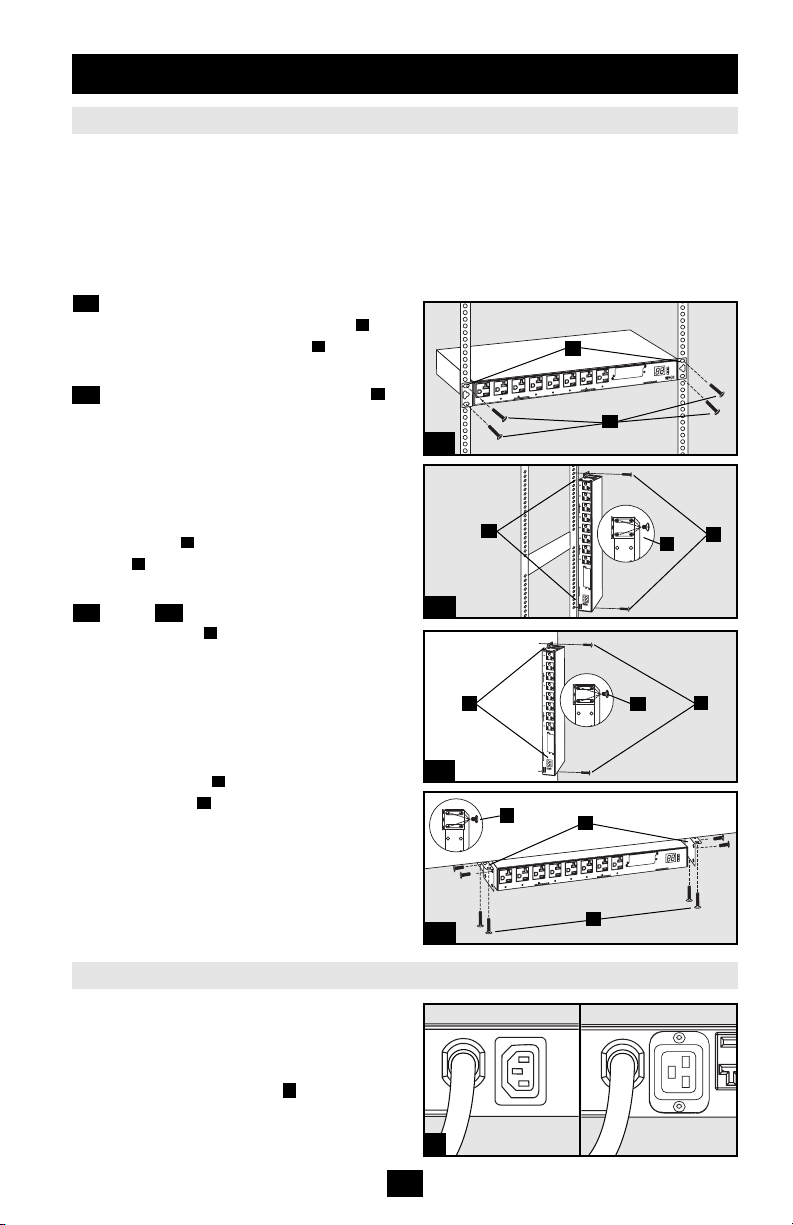
The PDU supports four primary mounting
configurations: 1U Rack, 0U Rack, Wall and
Under-Counter.
Note: Regardless of configuration, the user must determine the
fitness of hardware and procedures before mounting. The PDU
and included hardware are designed for common rack and rack
enclosure types and may not be appropriate for all
applications. Exact mounting configurations may vary.
1-1 1U Rack Mounting. Attach the PDU to the
rack by inserting four user-supplied screws
through the PDU mounting brackets and into
the mounting holes of the rack rail as shown.
1-2 0U Rack Mounting. Remove the screws
attaching the mounting brackets to the PDU,
change the orientation of the brackets as shown
and reattach the brackets. Use only the screws
supplied by the manufacturer or their exact
equivalent (#6-32, 1/4" flat head). Attach the
PDU vertically by inserting two or more usersupplied screws through the PDU mounting
brackets and into mounting points in the rack
A
B
or rack enclosure.
1-3 Wall or 1-4 Under-Counter Mounting.
Remove the screws attaching the mounting
C
brackets to the PDU, change the orientation of
the brackets as shown and reattach the brackets.
Use only the screws supplied by the
manufacturer or their exact equivalent (#6-32,
1/4" flat head). Attach the PDU to a stable
mounting surface by inserting two or more
user-supplied screws through the PDU
mounting brackets and into secure points on
A
B
the mounting surface.
A
B
B
C
A
1-1
B
A
C
1-2
B
C
A
1-3
C
B
Connecting the PDU
The PDU includes two AC power inputs:
Primary and Secondary. The Primary input cord
is permanently attached to the rear of the PDU.
The Secondary input cord is detachable and
connects to the IEC power inlet at the rear of
the PDU (PDUMH15AT - IEC-320-C14 inlet;
PDUMH20AT - IEC-320-C20 inlet).
2
1-4
2
PDUMH15AT
A
PDUMH20AT
3
Page 4
Installation
continued
Connecting the PDU
continued
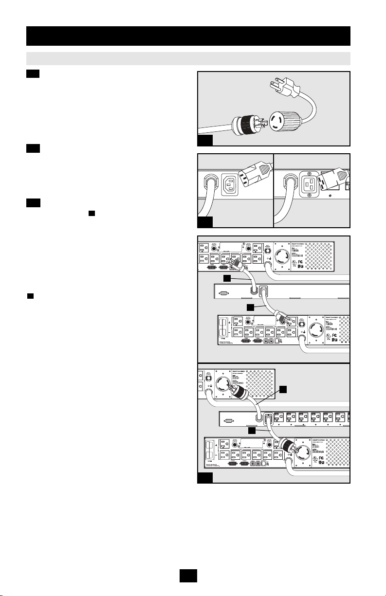
2-1 Connect Input Plug Adapters (Optional -
Model PDUMH20AT Only). The PDU
includes two adapters that convert one or both
of the L5-20P input plugs to 5-20P input plugs.
Connecting the adapters is optional. The PDU
will function normally without connecting the
adapters.
2-2 Connect Secondary Input Cord to PDU.
Although the PDU will operate without
connecting the Secondary input cord, the
Secondary input is required for the PDU's
Automatic Transfer Switch function.
2-3 Connect PDU Input Plugs. Connect the
Primary input plug to a preferred source of
grounded 120V AC power, such as a
SmartOnline
A
™
UPS System. The UPS system
must not share a circuit with a heavy electrical
load (such as an air conditioner or refrigerator).
Under normal operating conditions, the PDU
will distribute AC power from the Primary
input source. Connect the Secondary input plug
B
to an alternative source of grounded 120V
AC power, such as a redundant SmartOnline
™
UPS System. The UPS system must not share a
circuit with a heavy electrical load (such as an
air conditioner or refrigerator). Do not plug the
Secondary input into the same power source as
the Primary input. The PDU will distribute AC
power from the Secondary input only if the
Primary input becomes unavailable. See the
Configuration and Operation section for more
information.
Note: Immediately after the PDU is connected to live AC
power, you may notice a series of soft clicking sounds emitted
by electrical relays within the PDU. The relays may also click
occasionally during the operation of the PDU. This is normal.
2-1
2-2
PDUMH15AT
A
PDUMH20AT
PDUMH20AT
B
A
B
PDUMH15AT
PDUMH20AT
2-3
4
Page 5
Installation
continued
Connecting the PDU
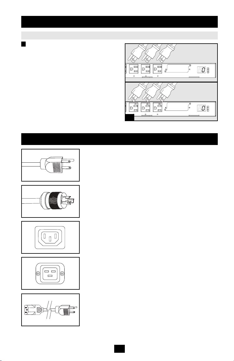
3 Connect Equipment to PDU. Do not exceed
the load rating of the PDU. The total electrical
current used by the PDU will be displayed on
the digital meter in amperes. Each outlet
includes a green LED that illuminates when the
outlet is receiving AC power.
continued
Features
Primary AC Input Power Cord (Model PDUMH15AT):
The cord is permanently attached to the PDU and has a NEMA
5-15P plug.
Primary AC Input Power Cord (Model PDUMH20AT):
The cord is permanently attached to the PDU and has a NEMA
L5-20P plug.
PDUMH15AT
PDUMH20AT
3
Secondary AC Input Power Inlet (Model PDUMH15AT): The
IEC-320-C14 inlet connects to the detachable Secondary AC
Input Power Cord.
Secondary AC Input Power Inlet (Model PDUMH20AT): The
IEC-320-C20 inlet connects to the detachable Secondary AC
Input Power Cord.
Secondary AC Input Power Cord (Model PDUMH15AT): The
detachable cord has an IEC-320-C13 connector and a NEMA
5-15P plug.
5
Page 6
Features
continued
Secondary AC Input Power Cord (Model PDUMH20AT): The
detachable cord has an IEC-320-C19 connector and a NEMA
L5-20P plug.
Input Plug Adapters (Model PDUMH20AT): The adapters
convert NEMA L5-20P input plugs to NEMA 5-20P input plugs.
NEMA 5-15R Outlets (Model PDUMH15AT): During normal
operation, the outlets distribute AC power to connected
equipment. When an outlet is live, the associated LED
illuminates.
NEMA 5-15/20R Outlets (Model PDUMH20AT): During
normal operation, the outlets distribute AC power to connected
equipment. When an outlet is live, the associated LED illuminates.
Digital Load Meter (Ammeter): The total electrical current used
by the PDU is displayed on the digital meter in amperes.
Input Source Indicator: When the PDU is connected to a live
AC power source, the Primary or Secondary input LED
illuminates to indicate which source is supplying power to the
PDU outlets.
Accessory Slot: An optional SNMP card may be installed in the
slot, allowing the PDU to be configured, controlled and
monitored remotely. Contact Tripp Lite Customer Support at
(773) 869-1234 for more information.
DB9 Port: The port is reserved for configuration by factory
authorized personnel only. Do not connect anything to the port.
Contact Tripp Lite Customer Support at (773) 869-1234 for more
information about options for extending the functionality of the
PDU.
6
Page 7
Configuration and Operation
Automatic Transfer Switch
When the Primary and Secondary inputs are both connected to Tripp Lite UPS Systems, the PDU
operates as an Automatic Transfer Switch, providing redundant input power for high availability
applications. Under normal operating conditions, the PDU will distribute power from the Primary
input source, switching to the Secondary input source under certain conditions. The PDU will switch
to the Primary source whenever it is Good according to the PDU input voltage definitions (see below).
Automatic Transfer Switch Source Selection
Upon power-up, the PDU looks for a source >85V. If it is unable to find a source >85V, it remains off.
Input voltage definitions:
in
99V < V
75V < V
V
In normal operation (after power-up), if the selected source is no longer Good, the PDU will attempt
to switch to the other source, but only if the other source is Good. If the selected source becomes Fair
and the other source is not Good, the PDU will keep the loads connected to the selected source until
the selected source becomes Bad, at which point the loads will be disconnected (note that the source
selection doesn't change). After the loads are disconnected, they remain disconnected until the
selected source becomes >85V, or until the other source becomes Good.
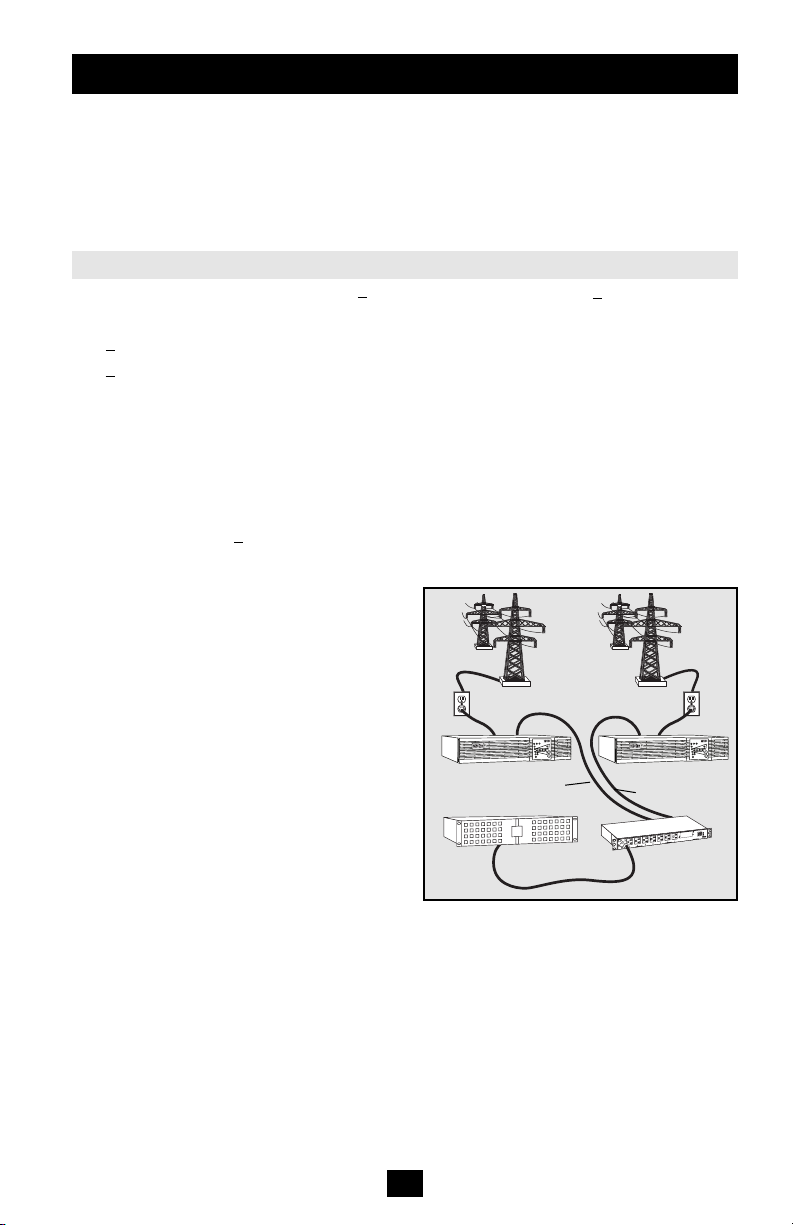
Preferred Configuration
The Automatic Transfer Switch function
provides increased availability when the
Primary and Secondary inputs of the PDU are
connected to separate Tripp Lite UPS Systems
that are connected to separate utility power
sources. For maximum availability, Tripp Lite
recommends using matching SmartOnline™
UPS Systems with pure sine wave output for
the Primary and Secondary input power
sources. The automatic transfer switch function
will be compromised if the primary and
secondary inputs are connected to the same
utility power source.
< 139V Good
in
< 99V Fair
in
< 75V Bad
Utility B
Facility Circuit
Secondary UPS
Secondary Input Cord
Critical Equipment
Loads
Utility A
Facility Circuit
Primary UPS
Primary Input Cord
PDUMH15AT
7
Page 8

Configuration and Operation
Quick Test
After installing the PDU and connecting
equipment, you may test the Automatic
Transfer Switch function by temporarily
shutting down the UPS system connected to the
Primary AC input. When the Primary input UPS
is no longer supplying AC power, the PDU will
switch from the Primary input to the Secondary
input, and the Secondary input LED will
illuminate. When the Primary input UPS has
been restarted and resumes supplying AC power,
the PDU will switch back to the Primary input.
Note: The primary and secondary inputs must be connected to
separate sources of utility power. The automatic transfer switch
function will be compromised if the primary and secondary
inputs are connected to the same utility power source. Do not
perform a test with equipment that must remain in productive
operation. Any test procedure must prepare for the contingency
that the equipment may lose power. Do not test the PDU by
detaching power cords which are connected to live power
sources, as this eliminates the connection to ground and places
your equipment at risk.
Enhanced Operation
Installing an SNMP card (the most recent
version of model SNMPWEBCARD) in the
accessory slot of the PDU allows remote,
network-enabled control of the receptacles.
With the addition of the SNMP card, the PDU
provides precise remote load management,
including sequenced power-up, receptacle
control, environmental monitoring and
automatic load shedding. Call Tripp Lite
Customer Support at (773) 869-1234 for more
information.
continued
Primary Input Active
Secondary Input Active
8
Page 9

Warranty and Warranty Registration
LIMITED WARRANTY
Seller warrants this product, if used in accordance with all applicable instructions, to be free from original defects in material
and workmanship for a period of 2 years (except internal UPS system batteries outside USA and Canada, 1 year) from the
date of initial purchase. If the product should prove defective in material or workmanship within that period, Seller will repair
or replace the product, in its sole discretion. Service under this Warranty can only be obtained by your delivering or shipping
the product (with all shipping or delivery charges prepaid) to: Tripp Lite, 1111 W. 35th Street, Chicago, IL 60609 USA. Seller
will pay return shipping charges. Call Tripp Lite Customer Service at (773) 869-1234 before sending any equipment back for
repair.
THIS WARRANTY DOES NOT APPLY TO NORMAL WEAR OR TO DAMAGE RESULTING FROM ACCIDENT, MISUSE,
ABUSE OR NEGLECT. SELLER MAKES NO EXPRESS WARRANTIES OTHER THAN THE WARRANTY EXPRESSLY SET
FORTH HEREIN. EXCEPT TO THE EXTENT PROHIBITED BY APPLICABLE LAW, ALL IMPLIED WARRANTIES,
INCLUDING ALL WARRANTIES OF MERCHANTABILITY OR FITNESS, ARE LIMITED IN DURATION TO THE WARRANTY
PERIOD SET FORTH ABOVE;AND THIS WARRANTY EXPRESSLY EXCLUDES ALL INCIDENTAL AND CONSEQUENTIAL
DAMAGES. (Some states do not allow limitations on how long an implied warranty lasts, and some states do not allow the
exclusion or limitation of incidental or consequential damages, so the above limitations or exclusions may not apply to you.
This Warranty gives you specific legal rights, and you may have other rights which vary from jurisdiction to jurisdiction).
WARNING:The individual user should take care to determine prior to use whether this device is suitable, adequate or safe for
the use intended. Since individual applications are subject to great variation, the manufacturer makes no representation or
warranty as to the suitability or fitness of these devices for any specific application.
WARRANTY REGISTRATION
Visit www.tripplite.com/warranty today to register the warranty for your new Tripp Lite product. You'll be automatically entered
into a drawing for a chance to win a FREE Tripp Lite product!*
* No purchase necessary.Void where prohibited. Some restrictions apply. See website for details.
FCC Notice
This device complies with part 15 of the FCC Rules. Operation is subject to the following two conditions: (1) This device may
not cause harmful interference, and (2) this device must accept any interference received, including interference that may
cause undesired operation.
This equipment has been tested and found to comply with the limits for a Class A digital device, pursuant to part 15 of the
FCC Rules. These limits are designed to provide reasonable protection against harmful interference when the equipment is
operated in a commercial environment. This equipment generates, uses, and can radiate radio frequency energy and, if not
installed and used in accordance with the instruction manual, may cause harmful interference to radio communications.
Operation of this equipment in a residential area is likely to cause harmful interference in which case the user will be required
to correct the interference at his own expense. The user must use shielded cables and connectors with this product. Any
changes or modifications to this product not expressly approved by the party responsible for compliance could void the user's
authority to operate the equipment.
Regulatory Compliance Identification Numbers
For the purpose of regulatory compliance certifications and identification, your Tripp Lite product has been assigned a unique
series number. The series number can be found on the product nameplate label, along with all required approval markings
and information. When requesting compliance information for this product, always refer to the series number. The series
number should not be confused with the marking name or model number of the product.
The policy of Tripp Lite is one of continuous improvement. Specifications are subject to change without notice.
9
Page 10

Manual del propietario
PDUMH15AT
PDUMH20AT
Unidad de distribución de potencia (PDU) para montaje
en bastidor con amperímetro e interruptor de
transferencia automático
Instrucciones de seguridad importantes
Instalación
Características
Configuración y operación
Garantía
English
Français
11
12
14
16
18
1
19
1111 W. 35th Street • Chicago, IL 60609 USA
(773) 869-1234 • www.tripplite.com
© 2006 Tripp Lite. Todos los derechos reservados. SmartOnline™es una marca comercial de Tripp Lite.
Page 11

Instrucciones de seguridad importantes
GUARDE ESTAS INSTRUCCIONES
Este manual contiene instrucciones y advertencias que deben
seguirse durante la instalación, operación y almacenamiento de
este producto. De no seguirlas, se anulará la garantía del producto.
• La PDU proporciona cómodas salidas múltiples, pero NO proporciona protección contra
sobretensión o ruido en la línea al equipo conectado.
• La PDU está diseñada sólo para empleo en interiores en un ambiente controlado, lejos del exceso
de humedad, temperaturas extremas, contaminantes conductores, polvo o luz solar directa.
• No conecte la PDU a una salida sin conexión a tierra ni a cables de extensión o adaptadores que
eliminen la conexión a tierra.
• El requisito de potencia de cada equipo conectado a la PDU no debe exceder la capacidad de carga
individual de la salida.
• El requisito de potencia total para el equipo conectado la PDU no debe exceder la máxima
capacidad de carga para la PDU.
• No taladre ni trate de abrir ninguna parte de la cubierta de la PDU. No hay partes en su interior que
requieran mantenimiento por parte del usuario.
• No intente modificar la PDU, incluyendo los enchufes de entrada y los cables de alimentación.
• No intente usar la PDU si alguno de sus componentes está dañado.
• No intente montar la PDU en una superficie insegura o inestable.
• Nunca intente instalar equipos eléctricos durante una tormenta eléctrica.
• El uso de este equipo en aplicaciones de soporte de vida en donde la falla de este equipo pueda
razonablemente hacer suponer que causará fallas en el equipo de soporte de vida o afecte
significativamente su seguridad o efectividad, no está recomendado. No use este equipo en la
presencia de una mezcla anestésica inflamable con aire, oxigeno u óxido nitroso.
11
Page 12

Instalación
Montaje de la PDU
La PDU soporta cuatro configuraciones básicas de
montaje: Bastidor de 1U, bastidor de 0U, de
pared y debajo de mostrador.
Nota: Independientemente de la configuración, el usuario debe
determinar la idoneidad de los materiales y accesorios así
como de los procedimientos antes del montaje. La PDU y el
material incluido están diseñados para racks (bastidores) y
cajas de rack (bastidor) comunes, y pueden no ser apropiados
para todas las aplicaciones.
1-1 Montaje en bastidor de 1U: Fije la PDU
al bastidor insertando cuatro tornillos
suministrados por el usuario a través de los
soportes de montaje de la PDU en los
agujeros de montaje del riel del bastidor como
se muestra.
1-2 Montaje en bastidor de 0U: Retire los
tornillos que fijan los soportes de montaje a
C
la PDU, cambie la orientación de los soportes
como se muestra y fíjelos nuevamente. Use
solo los tornillos incluidos o sus equivalentes
exactos (#6-32, 1/4" de cabeza plana). Fije la
PDU verticalmente insertando dos o más
tornillos suministrados por el usuario a
través de los soportes de montaje de la PDU
en los puntos de montaje en el bastidor o la caja
del bastidor.
1-3 Montaje en la pared o 1-4 debajo del
mostrador: Retire los tornillos que fijan los
soportes de montaje a la PDU, cambie la
orientación de los soportes como se muestra y
fíjelos nuevamente. Use solo los tornillos
incluidos o sus equivalentes exactos (#6-32,
1/4" de cabeza plana). Fije la PDU en una
superficie estable de montaje insertando dos o
más tornillos suministrados por el usuario a
través de los soportes de montaje de la PDU
en los puntos de montaje de la superficie.
A
B
A
B
C
A
B
1-1
1-2
1-3
1-4
B
A
B
B
C
C
B
A
A
C
A
Conexión de la PDU
La PDU incluye dos entradas de energía de CA:
Primaria y secundaria. El cordón de
alimentación primaria se encuentra conectado
permanentemente a la parte posterior de la
PDU. El cordón de alimentación secundaria es
separable y se conecta a la entrada de potencia
2
de IEC en la parte posterior de la PDU
(entrada PDUMH15AT - IEC-320-C14; entrada
PDUMH20AT - IEC-320-C20).
12
2
PDUMH15AT
PDUMH20AT
Page 13

Instalación
continuación
Conexión de la PDU
continuación
2-1 Conecte los adaptadores del enchufe de
entrada (Opcional - sólo para modelo
PDUMH20AT). La PDU incluye dos
adaptadores que transforman uno o ambos
enchufes de entrada L5-20P en enchufes de
entrada 5-20P. La conexión de los adaptadores
es opcional. La PDU funcionará de manera
normal sin conectar los adaptadores.
2-2 Conecte el cordón de alimentación
secundaria a la PDU. A pesar que la PDU
funcionará sin conectar el cordón de
alimentación secundaria, se requerirá la
alimentación secundaria para la función del
interruptor de transferencia automática de la PDU.
2-3 Conecte los enchufes de entrada de la
PDU. Conecte el enchufe de entrada primaria
A
a la fuente de energía que desee de CA de
120V puesta a tierra, tal como UPS
SmartOnline. Este sistema no deberá compartir
el circuito con ninguna carga eléctrica pesada
(por ejemplo aire acondicionado o
refrigeradora). Bajo condiciones normales de
operación, la PDU distribuirá energía de CA
desde la fuente de entrada primaria. Conecte el
enchufe de entrada secundaria a una fuente
B
alternativa de energía de CA de 120V puesta a
tierra, tal como el UPS SmartOnline. El UPS
no deberá compartir el circuito con ninguna
carga eléctrica pesada (por ejemplo aire
acondicionado o refrigeradora). No conecte la
entrada secundaria a la misma fuente de
energía, tal como hizo con la entrada primaria.
La PDU distribuirá energía de CA desde la
entrada secundaria sólo si la entrada primaria
no está disponible. Vea la sección
Configuración y operación para mayor
información.
Nota: Inmediatamente después de conectar la PDU a la
alimentación de energía de CA, usted podrá observar una serie
de ligeros clic emitidos por demoras eléctricas dentro de la
PDU. Ocasionalmente, estas demoras pueden también provocar
clics durante la operación de la PDU. Esto es normal.
2-1
2-2
2-3
PDUMH15AT
A
PDUMH20AT
PDUMH20AT
B
A
B
PDUMH15AT
PDUMH20AT
13
Page 14

Instalación
continuación
Conexión de la PDU
3 Conecte el equipo a la PDU. No exceda la
capacidad de carga de la PDU. La corriente
eléctrica total usada por la unidad de
distribución de potencia (PDU) será mostrada
en el medidor digital, en amperios. Cada salida
incluye un LED verde que se encenderá en el
instante que la salida recibe energía de CA.
continuación
Características
Cordón de alimentación de entrada de CA primaria (Modelo
PDUMH15AT): Este cordón se encuentra conectado
permanentemente a la PDU y tiene un enchufe NEMA 5-15P.
Cordón de alimentación de entrada de CA primaria (Modelo
PDUMH20AT): Este cordón se encuentra conectado
permanentemente a la PDU y tiene un enchufe NEMA L5-20P.
PDUMH15AT
PDUMH20AT
3
Cordón de alimentación de entrada de CA secundaria
(Modelo PDUMH15AT): La entrada IEC-320-C14 se conecta al
cordón de alimentación de entrada de CA secundaria separable.
Cordón de alimentación de entrada de CA secundaria
(Modelo PDUMH20AT): La entrada IEC-320-C20 se conecta al
cordón de alimentación de entrada de CA secundaria separable.
Cordón de alimentación de entrada de CA secundaria
(Modelo PDUMH15AT): El cordón separable tiene un conector
IEC-320-C13 y un enchufe NEMA 5-15P.
14
Page 15

Características
continuación
Cordón de alimentación de entrada de CA secundaria
(Modelo PDUMH20AT): El cordón separable tiene un conector
IEC-320-C19 y un enchufe NEMA L5-20P.
Adaptadores de enchufe de entrada (Modelo PDUMH20AT):
Los adaptadores transforman los enchufes de entrada NEMA L520P en enchufes de entrada NEMA 5-20P.
Salidas NEMA 5-15R (Modelo PDUMH15AT): Durante la
operación normal, las salidas distribuyen la energía de CA al
equipo conectado. Cuando hay energía en la salida, el LED
correspondiente se encenderá.
Salidas NEMA 5-15/20R (Modelo PDUMH20AT): Durante la
operación normal, las salidas distribuyen energía de CA al equipo
conectado. Cuando hay energía en la salida, el LED
correspondiente se encenderá.
Medidor digital de carga (Amperímetro): La corriente eléctrica
total usada por la unidad de distribución de potencia (PDU) será
mostrada en el medidor digital, en amperios.
Indicador de fuente de entrada: Al conectar la PDU a una
fuente de energía de CA, el LED de entrada primaria o secundaria
se encenderá para indicar cuál de las fuentes suministra energía a
las salidas de la PDU.
Ranura auxiliar: Una tarjeta SNMP opcional podrá ser instalada
en la ranura, permitiendo la configuración, el control y el
monitoreo remoto de la PDU. Contacte con el Soporte al cliente
de Tripp Lite al (773) 869-1234 para mayor información.
Puerto DB9: Este puerto está reservado para la configuración, la
cual deberá realizar solamente el personal autorizado por la
fábrica. No conecte nada al puerto. Contacte con el Soporte al
cliente de Tripp Lite al (773) 869-1234 para mayor información
sobre las opciones para ampliar la funcionalidad de la PDU.
15
Page 16

Configuración y operación
Interruptor de transferencia automática
Cuando las entradas primaria y secundaria se encuentren conectadas a la energía de CA, la PDU
funcionará como un interruptor de transferencia automático, suministrando energía redundante de
entrada a las aplicaciones de mayor disponibilidad. Bajo condiciones normales de operación, la PDU
distribuirá energía de CA al equipo conectado desde la fuente de entrada primaria, cambiando
automáticamente a la fuente de entrada secundaria bajo ciertas condiciones. La PDU cambiará a la
fuente primaria cuando sea buena dependiendo de las definiciones de voltaje en la entrada de la PDU
(vea a continuación). Las luces del LED ubicadas al lado del amperímetro, indican cuál de las fuentes
de energía de entrada suministra energía de CA al equipo conectado.
Selección de fuente del interruptor de transferencia automático
Al encenderse, la PDU busca una fuente >85V. Si no puede encontrar una fuente >85V, quedará apagada.
Definiciones de voltaje de entrada:
in
99V < V
75V < V
V
Durante la operación normal, (después de encenderlo), si la fuente seleccionada ya no es Buena, la
PDU intentará cambiar a otra fuente, sólo si la otra es Buena. Si la fuente seleccionada es Aceptable y
la otra fuente no es Buena, la PDU mantendrá las cargas conectadas a la fuente seleccionada hasta que
ésta sea Mala, desconectando las cargas en ese instante (fíjese que la selección de la fuente no
cambia). Después que las cargas son desconectadas, éstas continuarán en ese estado hasta que la
fuente seleccionada sea >85V, o hasta que la otra fuente sea Buena.
Configuración preferida
La función del interruptor de transferencia
automático proporciona una disponibilidad
aumentada cuando las entradas primaria y
secundaria de la PDU se conectan al UPS de
Tripp Lite separado que está conectado a
fuentes separadas de energía de la red. Para su
disponibilidad máxima, Tripp Lite recomienda
que haga coincidir el UPS SmartOnline con la
salida sinusoidal pura para las fuentes de
energía de entrada primaria y secundaria. La
función del interruptor de transferencia
automática estará comprometida si las entradas
primaria y secundaria están conectadas a la
misma fuente de energía de la red.
< 139V Buena
in
< 99V Aceptable
in
< 75V Mala
Red eléctrica B
Circuito de la
instalación B
UPS secundario
Cordón de alimentación
secundario
Cargas críticas del
equipo
Red eléctrica A
Circuito de la
instalación A
UPS primario
Cordón de
alimentación primario
PDUMH15AT
16
Page 17

Configuración y operación
Prueba rápida
Después de instalar la PDU y conectar el
equipo, usted podrá probar la función del
interruptor de transferencia automático
apagando temporalmente el UPS que está
conectado a la entrada de CA primaria. Cuando
el UPS de la entrada primaria ya no suministre
energía de CA, la PDU cambiará de entrada
primaria a entrada secundaria, y el LED de
entrada secundaria se encenderá. Cuando el
UPS de la entrada primaria haya sido reiniciado
y se reanude el suministro de energía de CA, la
PDU cambiará nuevamente a entrada primaria.
Nota: Las entradas primaria y secundaria deberán estar
conectadas a las fuentes separadas de energía de la red. La
función del interruptor de transferencia automática estará
comprometida si las entradas primaria y secundaria están
conectadas a la misma fuente de energía de la red. No realice
ninguna prueba con el equipo que debe quedar en operación
productiva. Se debe preparar algún procedimiento de prueba
para el caso en que el equipo pierda energía No pruebe la
PDU desconectando los cordones de alimentación que estén
conectados a fuentes de energía disponibles, ya que esto corta
la conexión a tierra y pone en peligro su equipo.
Operación mejorada
La instalación de la tarjeta SNMP (la versión
más reciente del modelo SNMPWEBCARD) en
la ranura auxiliar de la PDU permite el control
remoto de red de las tomas de corriente
habilitadas. Al agregar la tarjeta SNMP, la PDU
proporciona un manejo de carga remota precisa,
incluyendo encendido en secuencia, control de
contactos, monitoreo ambiental y retiro de
carga automático. Llame a Soporte al cliente de
Tripp Lite al (773) 869-1234 para mayor
información.
continuación
Entrada primaria activa
Entrada secundaria activa
17
Page 18

Garantía
GARANTÍA LIMITADA
El vendedor garantiza que este producto, si se emplea de acuerdo con todas las instrucciones aplicables, no tendrá defectos en
materiales ni mano de obra por un período de 2 años (salvo para baterías internas del UPS fuera de EE.UU. y Canadá, 1 año) a partir
de la fecha de compra. Si se verifica que el producto tiene defectos en los materiales o en la mano de obra dentro de dicho período, el
vendedor reparará o reemplazará el producto, a su sola discreción. Sólo puede obtenerse servicio bajo esta garantía, entregando o
despachando el producto (con todos los cargos de despacho o entrega pagados por adelantado) a: Tripp Lite, 1111 W. 35th Street,
Chicago, IL 60609 USA. El vendedor pagará los cargos de despacho del retorno. Llame al Servicio al cliente de Tripp Lite al (773) 8691234 antes de enviar algún equipo para reparación.
ESTA GARANTÍA NO SE APLICA AL DESGASTE NORMAL O A DAÑOS RESULTANTES DE UN ACCIDENTE, USO INADECUADO,
MALTRATO O NEGLIGENCIA. EL VENDEDOR NO EXPRESA NINGUNA OTRA GARANTÍA DISTINTA DE LA ESTABLECIDA EN ESTE
DOCUMENTO EN FORMA EXPLÍCITA. EXCEPTO HASTA EL GRADO PROHIBIDO POR LAS LEYES APLICABLES, TODAS LAS
GARANTÍAS IMPLÍCITAS, INCLUYENDO TODAS LAS GARANTÍAS DE COMERCIABILIDAD O IDONEIDAD, ESTÁN LIMITADAS EN
DURACIÓN AL PERÍODO DE GARANTÍA ESTABLECIDO ANTERIORMENTE; ESTA GARANTÍA EXCLUYE EXPRESAMENTE TODOS
LOS DAÑOS INCIDENTALES Y CONSECUENTES. (Algunos estados no permiten limitaciones sobre la duración de una garantía
implícita, y algunos estados no permiten la exclusión o limitación de daños incidentales o consecuentes, de modo que las limitaciones
o exclusiones mencionadas pueden no aplicarse a usted. Esta garantía le da derechos legales específicos, pero usted puede tener otros
derechos que varían de jurisdicción a jurisdicción.)
ADVERTENCIA: El usuario individual debe encargarse de determinar antes de usarlo, si este dispositivo es apropiado, adecuado o
seguro para el uso proyectado.Ya que las aplicaciones individuales están sujetas a gran variación, el fabricante no declara ni garantiza
la idoneidad o aptitud de estos dispositivos para ninguna aplicación específica.
CONSULTE SUS CONDICIONES DE GARANTÍA POR PRODUCTO
Este equipo marca Tripp Lite, modelo _______________ está garantizado por TRIPP LITE, que tiene su domicilio en la calle de Sierra
Candela No.111-107, Col Lomas de Chapultepec, CP 11000, México, DF, y puede hacer efectiva su garantía así como obtener partes,
componentes, consumibles y accesorios en el Centro de Servicio Q PLUS ubicado en Av Coyoacan 931, Col. Del Valle, C.P. 03120
México. D.F., tel. 50 00 27 00 contra cualquier defecto de fabricación y funcionamiento, imperfecciones de materiales, piezas,
componentes y mano de obra al consumidor acorde a la siguiente tabla:
Producto Modelo Vigencia
Sistema de Energía Ininterrumpible (UPS) Familia: BC, OMNI, SMART, SMARTONLINE MONOFASICOS 2 Años
Sistema de Energía Ininterrumpible (UPS) Familia: SMARTONLINE 3PH 1 Año
Regulador y Acondicionador de Tensión Familia: LS, LC 2 Años
Inversores Familia: APS, PV 2 Años
Multiplexor y Conmutador Familia: KVM 5 Años
Conmutador Modelo: B020-016 6 Meses
Supresor de Picos de Tensión Familia: PROTECT IT, ISOBAR 25 Años
1. Para hacer válida su garantía no podrán exigirse mayores requisitos que la presentación de esta póliza debidamente
llenada y sellada por el establecimiento que lo vendió junto con el producto en el lugar donde fue adquirido.
2. TRIPP LITE, se compromete a reparar, y en caso de que a su juicio no sea posible la reparación, a cambiar el equipo, así
como las piezas y componentes defectuosos del mismo sin cargo alguno para el propietario durante el periodo de
garantía, así como los gastos de transportación razonablemente erogados del producto que deriven de su cumplimiento,
dentro de su red de servicio.
3. El tiempo de reparación en ningún caso será mayor de 30 días contados a partir de la fecha de recepción del producto
en el Centro Autorizado de Servicio, en donde también podrán adquirir refacciones y partes.
4. En caso de que la presente póliza de garantía se extraviara, el consumidor puede recurrir a su proveedor para que expida
un duplicado de la póliza de garantía, previa presentación de la nota de compra o factura correspondiente.
Esta garantía no es válida en los siguientes casos:
a) Cuando el producto se hubiese utilizado en condiciones distintas a la normales.
b) Cuando el producto no hubiese sido operado de acuerdo con el instructivo de uso que se le acompaña.
c) Cuando el producto hubiese sido alterado o reparado por personas no autorizadas por el fabricante nacional,
importador o comercializador responsable respectivo.
Este equipo fue vendido por: _____________________________________
con domicilio en _______________________________________________
el día _____ de ___________ de ________, fecha a partir de la que inicia la presente garantía.
Aviso de la FCC
Este dispositivo cumple con la sección 15 de las reglas de la FCC. La operación adecuada está sujeta a las siguientes dos
condiciones: (1) Este dispositivo no debe causar interferencias dañinas y (2) este dispositivo debe aceptar cualquier interferencia
recibida, incluyendo la interferencia que podría causar una operación no intencional.
Nota: Se ha comprobado que este dispositivo cumple con los límites designados para un dispositivo digital de la Clase A de acuerdo
con la parte 15 de las Regulaciones de FCC. Estos límites se diseñaron para proporcionar protección razonable contra interferencias
perjudiciales cuando la unidad es operada en entornos comerciales. Este equipo genera, utiliza y puede radiar energía de radio
frecuencia y, si no es instalado y utilizado de acuerdo con las instrucciones del manual de operación, puede causar interferencias
perjudiciales a las comunicaciones de radio. La operación de este equipo en un área residencial puede causar interferencias
perjudiciales. En tal caso, se puede requerir que el usuario corrija dichas interferencias y sea responsable por los costos de esta
corrección. El usuario debe utilizar en este producto conectores y cables blindados. Cualquier cambio o modificación a este producto,
no aprobados de manera expresa, por parte del responsable del cumplimiento de las normas, invalidará la autorización del usuario
para operar el equipo.
Cumplimiento de las normas de los números de identificación
Para fines de identificación y certificación del cumplimiento de las normas, su producto Tripp Lite tiene asignado un número de serie
único. Puede encontrar el número de serie en la etiqueta de la placa de identificación del producto, junto con los símbolos de aprobación
e información requeridos. Al solicitar información sobre el cumplimiento de las normas para este producto, siempre mencione el número
de serie. El número de serie no debe ser confundido con el nombre de identificación ni con el número de modelo del producto.
Tripp Lite tiene una política de mejoramiento continuo. Las especificaciones están sujetas a cambio sin previo aviso.
LEA SU INSTRUCTIVO
PÓLIZA DE GARANTÍA
CONDICIONES
EXCLUSIONES
18
Page 19

Manuel du propriétaire
PDUMH15AT
PDUMH20AT
Unité de distribution d'alimentation (PDU) en bâti avec
ampèremètre et commutateur de transfert automatique
Importantes consignes de sécurité
Installation
Caractéristiques
Configuration et fonctionnement
Garantie
English
Español
20
21
23
25
27
1
10
1111 W. 35th Street • Chicago, IL 60609 USA
(773) 869-1234 • www.tripplite.com
Copyright 2006 Tripp Lite. Tous droits réservés. SmartOnline™est une marque déposée de Tripp Lite.
Page 20

Importantes consignes de sécurité
CONSERVER CES DIRECTIVES
Ce manuel contient des instructions et des mises en garde que vous
devez respecter durant l’installation, l’utilisation et l’entreposage de ce
produit. Le non-respect de ces instructions et mises en garde annulera
la garantie du produit.
• L’unité PDU offre de nombreuses prises pratiques mais elle N’offre PAS de protection contre les
surtensions transitoires et les parasites à l’équipement connecté.
• L’unité PDU est conçue pour un usage en environnement contrôlé, à l’abri de l’humidité excessive,
des températures extrêmes, des contaminants conducteurs, de la poussière ou de la lumière directe
du soleil.
• Ne pas connecter l’unité PDU à une prise sans mise à la terre ou à des cordons prolongateurs ou
des adaptateurs qui éliminent la mise à la terre.
• La demande d'alimentation pour chaque pièce d'équipement connectée à l'unité PDU ne doit pas
dépasser la charge nominale d'une prise individuelle.
• La demande totale d'alimentation pour l'équipement connectée à l'unité PDU ne doit pas dépasser
la charge nominale maximale pour l'unité PDU.
• Ne jamais percer ou essayer d’ouvrir une quelconque partie du boîtier de l’unité PDU. Aucune
pièce interne ne peut être réparée par l’utilisateur.
• Ne pas essayer de modifier l’unité PDU, y compris les fiches d’entrée et les câbles d’alimentation.
• Ne pas essayer d’utiliser l’unité PDU, si une de ses pièces est endommagée.
• Ne pas essayer de monter l’unité PDU sur une surface peu sûre ou instable.
• Ne jamais essayer de d’installer un équipement électrique pendant un orage.
• Il est déconseillé d'utiliser cet équipement dans des applications médicales où une panne de cet
équipement pourrait normalement provoquer la panne de l'équipement de survie ou altérer
otablement sa sécurité ou son efficacité. Ne pas utiliser cet équipement en présence d'un mélange
anesthétique inflammable avec de l'air, de l'oxygène ou de l'oxyde nitreux.
20
Page 21

Installation
Montage de l'unité de distribution d'alimentation (PDU)
L'unité peut être montée selon quatre
configurations principales : Baie 1U, Baie 0U,
contre un mur ou sous un comptoir.
Nota : Sans tenir compte de la configuration, l'utilisateur doit
déterminer la compatibilité de la quincaillerie et les procédures
avant d'effectuer l'installation. L'unité PDU et la quincaillerie
incluse sont conçues pour des types de bâti et boîtier courants
et peuvent ne pas convenir à toutes les applications.
1-1 Montage en bâti 1U : Fixer la PDU à la
baie en insérant quatre vis fournies par
l'utilisateur dans les brides des fixation de
l'unité et dans les trous de fixation de la
glissière de la baie comme indiqué.
1-2 Montage en bâti 0U : Retirer les vis
fixant les brides de fixation à la PDU, changer
l'orientation des brides comme indiqué et les
fixer à nouveau. Utiliser seulement les vis
jointes ou leur équivalent exact (N° 6-32, tête
plate 1/4 po [6,4 mm]). Fixer la PDU
verticalement en insérant deux vis ou plus ,
fournies par l'utilisateur dans les brides de
B
fixation de l'unité et dans les points de
fixation de la baie ou de son boîtier.
1-3 Montage au mur ou 1-4 sous un
comptoir : Retirer les vis fixant les brides de
fixation à la PDU, changer l'orientation des
brides comme indiqué et les fixer à nouveau.
Utiliser seulement les vis jointes ou leur
équivalent exact (N° 6-32, tête plate 1/4 po [6,4
mm]). Fixer la PDU sur une surface de fixation
stable en insérant deux vis ou plus , fournies
par l'utilisateur dans les brides de fixation de
l'unité et dans des points de fixation sûrs de la
surface.
A
B
C
A
1-1
B
B
1-2
C
B
1-3
A
B
C
A
A
C
C
B
A
1-4
A
Connexion de l'unité de distribution d'alimentation (PDU)
La PDU dispose de deux entrées de courant
alternatif : Primaire et secondaire. Le cordon
alimentation d'entrée primaire est fixé en
permanence à l'arrière de la PDU. Le cordon
alimentation d'entrée secondaire est amovible et
connecté à l'embase d'alimentation électrique
2
à l'arrière de la PDU (PDUMH15AT embase IEC-320-C14; PDUMH20AT - embase
IEC-320-C20).
21
2
PDUMH15AT
PDUMH20AT
Page 22

Installation
suite
Connexion de l'unité de distribution d'alimentation (PDU)
2-1 Connecter les adaptateurs d'entrée
enfichables (En option - Modèle
PDUMH20AT uniquement). La PDU
comprend deux adaptateurs qui convertissent la
ou les deux fiches d'entrée L5-20P en fiches
d'entrée 5-20P. La connexion des adaptateurs
est optionnelle. La PDU fonctionnera
normalement sans connexion aux adaptateurs.
2-2 Connecter le cordon d'alimentation
d'entrée secondaire à la PDU. Même si la
PDU fonctionne sans le cordon d'alimentation
d'entrée secondaire, la fonction du commutateur
de transfert automatique a besoin de l'entrée
secondaire.
2-3 Connecter les fiches d'entrée de la PDU.
Connecter la fiche d'entrée primaire à une
A
source préférée de courant 120 V CA mise à la
terre, comme un système d'onduleur
SmartOnline. Le système d'onduleur ne doit pas
partager de circuit avec une charge électrique
lourde (comme un climatiseur ou un
réfrigérateur). Dans des conditions normales de
fonctionnement, la PDU distribuera du courant
CA de la source d'entrée primaire. Connecter la
fiche secondaire à une source alternative de
B
courant 120V CA, comme un système
redondant d'onduleur SmartOnline. Le système
d'onduleur ne doit pas partager de circuit avec
une charge électrique lourde (comme un
climatiseur ou un réfrigérateur). Ne pas
brancher l'entrée secondaire sur le même circuit
que l'entrée primaire. La PDU distribuera le
courant CA depuis l'entrée secondaire
uniquement si l'entrée primaire n'est pas
disponible. Voir le chapitre Configuration et
fonctionnement pour plus de renseignements.
Note : Immédiatement après avoir connecté la PDU un circuit
CA sous tension, vous pourriez remarquer une série de légers
cliquètements émis par les relais électriques dans la PDU. Ces
relais pourraient aussi cliqueter occasionnellement lors du
fonctionnement de la PDU. C'est normal.
2-1
2-2
2-3
PDUMH15AT
A
B
A
B
suite
PDUMH20AT
PDUMH20AT
PDUMH15AT
PDUMH20AT
22
Page 23

Installation
suite
Connexion de l'unité de distribution d'alimentation (PDU)
3 Connecter l'équipement à la PDU. Ne pas
dépasser la capacité de charge de la PDU.
Ampèremètres : La totalité du courant
électrique utilisée par la PDU sera affichée en
ampères au compteur numérique. Chaque sortie
dispose d'une DEL verte qui s'allume quand la
sortie reçoit du courant CA.
3
Caractéristiques
Cordon d'alimentation d'entrée primaire CA (Modèle
PDUMH15AT) : Ce cordon est fixé en permanence à la PDU et
dispose d'une fiche NEMA 5-15P.
Cordon d'alimentation d'entrée primaire CA (Modèle
PDUMH20AT) : Ce cordon est fixé en permanence à la PDU et
dispose d'une fiche NEMA L5-20P.
suite
PDUMH15AT
PDUMH20AT
Cordon d'alimentation d'entrée secondaire CA (Modèle
PDUMH15AT) : Le cordon d'alimentation d'entrée secondaire
CA amovible se connecte à l'embase IEC-320-C14.
Cordon d'alimentation d'entrée secondaire CA (Modèle
PDUMH20AT) : Le cordon d'alimentation d'entrée secondaire
CA amovible se connecte à l'embase IEC-320-C20.
Cordon d'alimentation d'entrée secondaire CA (Modèle
PDUMH15AT) : Le cordon amovible dispose d'un connecteur
IEC-320-C13 et d'une fiche NEMA 5-15P.
23
Page 24

Caractéristiques
suite
Cordon d'alimentation d'entrée secondaire CA (Modèle
PDUMH20AT) : Le cordon amovible dispose d'un connecteur
IEC-320-C19 et d'une fiche NEMA L5-20P.
Adaptateurs d'entrée enfichables (Modèle PDUMH20AT) :
Les adaptateurs convertissent les fiches NEMA L5-20P en fiches
NEMA 5-20P.
Sorties NEMA 5-15R (Modèle PDUMH15AT) : Lors d'un
fonctionnement normal, les sorties distribuent du courant CA à
l'équipement connecté. Quand une sortie est sous tension, la DEL
correspondante s'allume.
Sorties NEMA 5-15R/20R (Modèle PDUMH20AT) : Lors d'un
fonctionnement normal, les sorties distribuent du courant CA à
l'équipement connecté. Quand une sortie est sous tension, la DEL
correspondante s'allume.
Compteur numérique de charge (Ampèremètre) : La totalité
du courant électrique utilisée par la PDU sera affichée en ampères
au compteur numérique.
Témoin de source d'entrée : Lorsque la PDU est connectée à
une source sous tension de courant CA, La DEL d'entrée primaire
ou secondaire s'allume pour indiquer quelle source alimente les
sorties de la PDU.
Fente d'accessoire : Vous pouvez installer une carte SNMP
optionnelle dans la fente, ce qui permet de configurer,
commander et surveiller la PDU à distance. Appeler l'assistance à
la clientèle de Tripp Lite au (773) 869-1234 pour plus de
renseignements.
Port DB9 : Ce port est réservé pour la configuration en usine
uniquement par du personnel autorisé. Ne rien connecter à ce
port. Appeler l'assistance à la clientèle de Tripp Lite au (773) 8691234 pour plus de renseignements au sujet des options permettant
d'étendre la fonctionnalité de la PDU.
24
Page 25

Configuration et fonctionnement
Commutateur de transfert automatique
Lorsque les entrées primaire et secondaire sont toutes deux connectées au courant CA, la PDU agit
comme un commutateur de transfert automatique, fournissant une alimentation d'entrée redondante
pour des applications à haute disponibilité. Dans des conditions normales de fonctionnement, la PDU
distribuera du courant CA de la source d'entrée primaire à l'équipement connecté, permutant à la
source d'entrée secondaire automatiquement dans certaines conditions. La PDU permutera à la source
primaire chaque fois qu'elle est bonne selon les définitions de tension d'entrée de la PDU (Voir cidessous). Les témoins lumineux DEL situés près du compteur numérique de charge indique quelle
source d'alimentation d'entrée source fournit le courant CA l'équipement connecté.
Choix de source de commutateur de transfert automatique
À la mise en marche, la PDU recherche une source >85V. Si elle est incapable de trouver une source
>85V, elle restera fermée.
Définitions de tension d'entrée:
99V < Tension d'entrée < 139V bonne
75V < Tension d'entrée < 99V passable
Tension d'entrée < 75V insuffisante
En fonctionnement normal (après mise en marche), si la source choisie n'est plus bonne, la PDU
essaiera de permuter vers l'autre source, mais seulement si l'autre source est bonne. Si la source
choisie devient passable et que l'autre source n'est pas bonne, la PDU conservera les charges
connectées à la source choisie jusqu'à ce que celle-ci devienne insuffisante; à ce moment là, les
charges seront déconnectées (noter que le choix de la source ne change pas). Une fois les charges
déconnectées, elles le restent jusqu'à ce que la source choisie devienne >85V, ou que d'autre source
devienne bonne.
Configuration préférée
La fonction du commutateur de transfert
automatique offre une disponibilité accrue
quand les entrées primaire et secondaire de la
PDU sont connectées à des systèmes d'onduleur
Tripp Lite eux-mêmes connectés à des sources
séparées d'alimentation de secteur. Pour une
disponibilité maximale, Tripp Lite recommande
d'utiliser les systèmes d'onduleur SmartOnline
correspondant avec sortie sinusoïdale pure pour
les sources d'alimentation d'entrée primaire et
secondaire. La fonction du commutateur de
transfert automatique sera compromise si les
entrées primaire et secondaire sont connectées à
la même source d'alimentation de secteur.
25
Réseau
électrique B
Circuit B
Onduleur secondaire
Cordon d'alimentation
d'entrée secondaire
Charges critiques
d'équipement
Réseau
électrique A
Circuit A
Onduleur primaire
Cordon d'alimentation
d'entrée primaire
PDUMH15AT
Page 26

Configuration et fonctionnement
Test rapide
Après avoir installé la PDU et connecté
l'équipement, vous pouvez tester la fonction du
commutateur de transfert automatique en
fermant temporairement le système d'onduleur
connecté à l'entrée CA primaire. Si l'onduleur
d'entrée primaire n'alimente plus en courant
CA, la PDU permutera de l'entrée primaire à
l'entrée secondaire et la DEL d'entrée
secondaire s'allumera Lorsque l'onduleur
d'entrée primaire est redémarré et fournit à
nouveau du courant CA, la PDU permutera sur
l'entrée primaire.
Note: les entrées primaire et secondaire doivent être connectées
à des sources séparées d'alimentation de secteur. La fonction du
commutateur de transfert automatique sera compromise si les
entrées primaire et secondaire sont connectées à la même
source d'alimentation de secteur. Ne pas faire de test avec de
l'équipement qui doit rester en production. Lors de la procédure
de test, il faut s'attendre à ce que l'alimentation manque à
l'équipement. Ne pas tester la PDU en débranchant des cordons
connectés à des sources alimentation sous tension, car cela
éliminera la connexion à la terre et mettra votre équipement en
danger.
Fonctionnement amélioré
L'installation d'une carte SNMP (la version la
plus récente du modèle SNMPWEBCARD)
dans la fente d'accessoire de la PDU permet la
commande des prises à distance à partir de
réseaux. Avec l'ajout de la carte SNMP, la PDU
offre une gestion précise des charges à distance,
y compris la mise en marche successifs, la
commande des prises, la surveillance
environnementale et le délestage automatique
des charges. Appeler l'assistance à la clientèle
de Tripp Lite au (773) 869-1234 pour plus de
renseignements.
suite
Entrée primaire active
Entrée secondaire active
26
Page 27

Garantie
GARANTIE LIMITÉE
Le vendeur garantit que ce produit, s'il est utilisé selon toutes les directives applicables, est exempt de défauts d'origine de
matériel et de main-d'œuvre pour une période de 2 ans (à l'exception des batteries interne du système UPS hors des É. U.
et du Canada, 1 an) à partir de la date initiale d'achat. Si le produit s'avère défectueux en matériel ou en main-d'œuvre durant
cette période, le vendeur réparera ou remplacera le produit à sa discrétion. Vous pouvez obtenir un service selon cette
garantie seulement en livrant ou en expédiant le produit (avec les frais d'expédition et de livraison prépayés) à : Tripp Lite,
1111 W. 35th Street, Chicago, IL 60609 USA.Le vendeur paierai les frais d'expédition de retour. Communiquer avec le service
à la clientèle de Tripp Lite au (773) 869-1234 avant d'envoyer un équipement pour réparations.
CETTE GARANTIE NE S'APPLIQUE PAS À L'USURE NORMALE OU AUX DOMMAGES RÉSULTANT D'ACCIDENTS, DE
MAUVAIS USAGE, D'ABUS OU DE NÉGLIGENCE. LE VENDEUR N'OFFRE AUCUNE GARANTIE EXPLICITE AUTRE QUE
LA GARANTIE EXPRESSÉMENT SIGNIFIÉE À LA PRÉSENTE. EXCEPTÉ SELON LES LIMITES DE LA LOI APPLICABLE,
TOUTES LES GARANTIES IMPLICITES, Y COMPRIS TOUTES LES GARANTIES DE QUALITÉ MARCHANDE OU DE
CONFORMITÉ À UN BESOIN PARTICULIER, SONT LIMITÉES EN DURÉE À LA PÉRIODE DE GARANTIE ÉNONCÉE CI
DESSUS ET CETTE GARANTIE EXCLUE EXPLICITEMENT TOURS LES DOMMAGES ACCESSOIRES OU
CONSÉCUTIFS. Certains états ne permettent pas la limitation de la durée d'une garantie implicite et certains états ne
permettent pas la limitation ou l'exclusion de dommages accessoires ou consécutifs, en conséquence, les limitations et les
exclusions ci dessus pourraient ne pas s'appliquer à vous. Cette garantie vous donne des droits légaux spécifiques et vous
pourriez avoir d'autres droits selon les juridictions.
MISE EN GARDE : L'utilisateur devra prendre soin de déterminer avant de l'utiliser si cet appareil convient, est adéquat et sûr
pour l'usage prévu. Puisque les applications individuelles sont sujettes à de grandes variations, le fabricant ne fait aucune
représentation ni n'offre de garantie quand à l'applicabilité et à la conformité de ces appareils pour une application particulière.
Notification de FCC
Ce périphérique est conforme à la section 15 des règlements de la FCC. Son utilisation est assujettie aux deux conditions
suivantes : (1) Ce périphérique ne peut pas produire de brouillage nuisible, et (2) il doit accepter tout brouillage reçu, y compris
ceux qui peuvent avoir des effets préjudiciables.
Ce matériel a été testé et s'est avéré être conforme aux limites des dispositifs numériques de Classe A, conformément à la
partie 15 du règlement de la FCC. Ces limites sont conçues pour fournir à une installation commerciale une protection
raisonnable contre les brouillages nuisibles. Ce matériel produit, utilise et peut émettre de l'énergie de fréquence radio et s'il
n'est pas installé et utilisé conformément au guide d'instructions, celui-ci peut causer un brouillage dans les communications
radio. L'utilisation de ce matériel dans un secteur résidentiel peut causer un brouillage nuisible qui devra être corrigé au frais
de l'utilisateur. L'utilisateur doit faire usage de câbles et de connecteurs blindés avec ce produit. Tout changement ou toute
modification apportés à ce produit qui ne sont pas expressément acceptés par la partie responsable de la conformité aux
normes peuvent annuler le droit de l'utilisateur d'exploiter cet équipement.
Numéros d’identification de conformité aux règlements
À des fins de certification et d’identification de conformité aux règlements, votre produit Tripp Lite a reçu un numéro de série
unique. Ce numéro se retrouve sur la plaque signalétique du produit, avec les inscriptions et informations d’approbation
requises. Lors d’une demande d’information de conformité pour ce produit, utilisez toujours le numéro de série. Il ne doit pas
être confondu avec le nom de la marque ou le numéro de modèle du produit.
La politique de Tripp Lite est celle d'une amélioration continuelle. Les spécifications peuvent être modifiées sans préavis.
27
Page 28

1111 W. 35th Street • Chicago, IL 60609 USA
(773) 869-1234 • www.tripplite.com
28
200706235 93-2702
 Loading...