

Page 1
WARRANTY
REGISTRATION
Register online today for a
chance to win a FREE Tripp Lite
product! www.tripplite.com/warranty
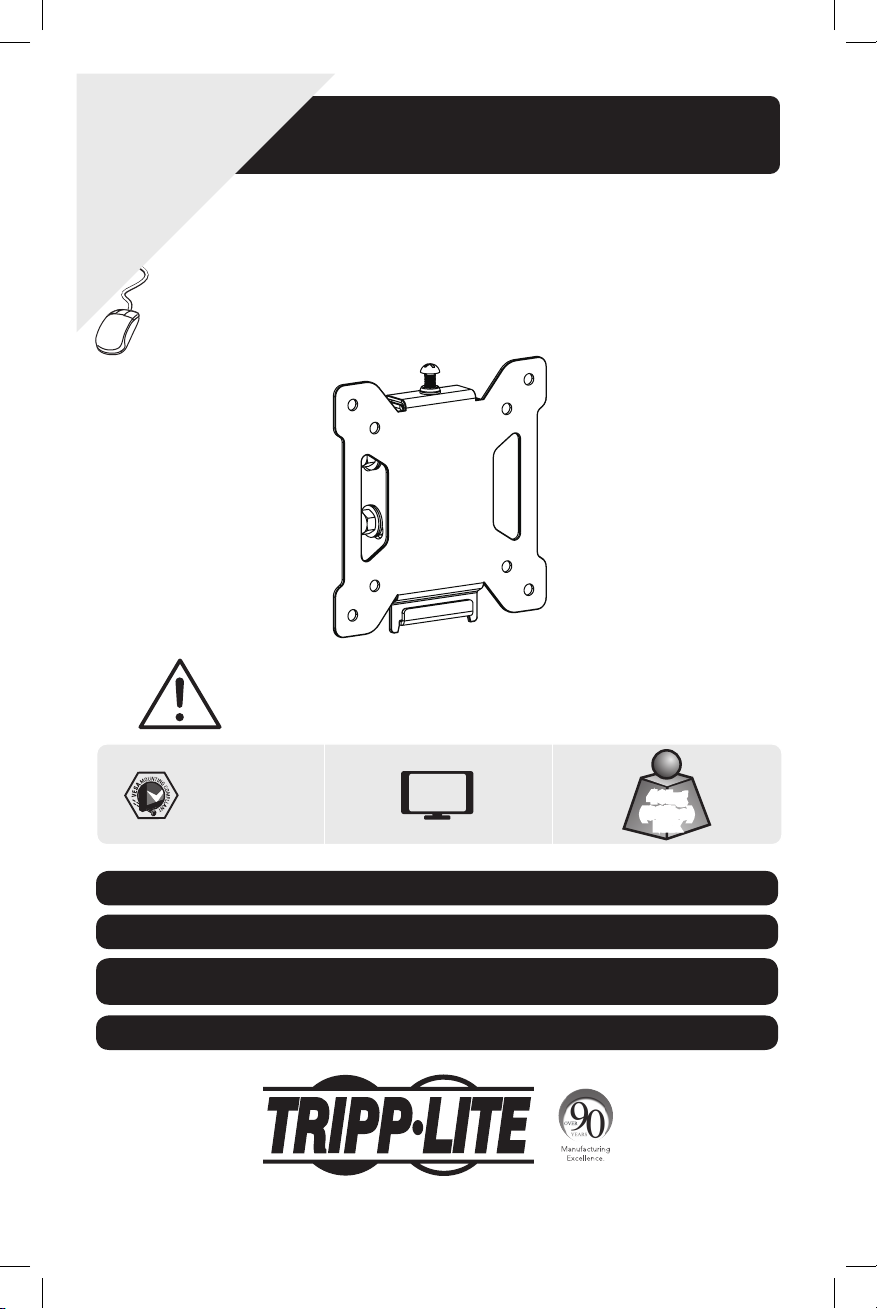
Tilt Flat Screen
CAUTION: DO NOT EXCEED MAXIMUM LISTED WEIGHT CAPACITY. SERIOUS INJURY OR
PROPERTY DAMAGE MAY OCCUR!
Owner’s Manual
Wall Mount
MODEL: DWT1323S
75x75/100x100
Este manual esta disponible en español en la página de Tripp Lite: www.tripplite.com
Ce manuel est disponible en français sur le site Web de Tripp Lite : www.tripplite.com
Русскоязычная версия настоящего руководства представлена на веб-сайте компании
Tripp Lite по адресу: www.tripplite.com
Dieses Handbuch ist in deutscher Sprache auf der Tripp Lite-Website verfügbar: www.tripplite.com
1111 W. 35th Street, Chicago, IL 60609 USA • www.tripplite.com/support
Copyright © 2013 Tripp Lite. All rights reserved.
13-09-229-93-32A5-EN.indd 1 10/31/2013 9:59:04 AM
27”
MAX
1
40kg
(88lbs)
MAX
Page 2

NOTE: Read the entire instruction manual before you start installation and assembly.
WARNING
• Do not begin the installation until you have read and understood the instructions
and warnings contained in this manual. If you have any question regarding any of
the instructions or warnings, please visit www.tripplite.com/support.
• This mounting bracket was designed to be installed and utilized ONLY as
specified in this manual. Improper installation of this product may cause damage
or serious injury.
• This product should only be installed by someone of good mechanical ability,
with basic building experience and a full understanding of this manual.
• Make sure that the supporting surface will safely support the combined load of
the equipment and all attached hardware and components.
• If mounting to wood wall studs, make sure that mounting screws are anchored
into the center of the studs. The use of a stud finder is highly recommended.
• Always use an assistant or mechanical lifting equipment to safely lift and position
equipment.
• Tighten screws rmly, but do not over tighten. Over tightening can damage the
items, greatly reducing their holding power.
• This product is intended for indoor use only. Using this product outdoors could
lead to product failure and personal injury.
Warranty & Warranty Registration
5-Year Limited Warrant
Seller warrants this product, if used in accordance with all applicable instructions, to be free from original defects
in material and workmanship for a period of 5 years from the date of initial purchase. If the product should
prove defective in material or workmanship within that period, Seller will repair or replace the product, in its sole
discretion.
THIS WARRANTY DOES NOT APPLY TO NORMAL WEAR OR TO DAMAGE RESULTING FROM ACCIDENT, MISUSE,
ABUSE OR NEGLECT. SELLER MAKES NO EXPRESS WARRANTIES OTHER THAN THE WARRANTY EXPRESSLY
SET FORTH HEREIN. EXCEPT TO THE EXTENT PROHIBITED BY APPLICABLE LAW, ALL IMPLIED WARRANTIES,
INCLUDING ALL WARRANTIES OF MERCHANTABILITY OR FITNESS, ARE LIMITED IN DURATION TO THE WARRANTY
PERIOD SET FORTH ABOVE; AND THIS WARRANTY EXPRESSLY EXCLUDES ALL INCIDENTAL AND CONSEQUENTIAL
DAMAGES. (Some states do not allow limitations on how long an implied warranty lasts, and some states do not
allow the exclusion or limitation of incidental or consequential damages, so the above limitations or exclusions
may not apply to you. This warranty gives you specific legal rights, and you may have other rights which vary from
jurisdiction to jurisdiction).
WARNING: The individual user should take care to determine prior to use whether this device is suitable, adequate
or safe for the use intended. Since individual applications are subject to great variation, the manufacturer makes
no representation or warranty as to the suitability or fitness of these devices for any specific application.
WARRANTY REGISTRATION
Visit www.tripplite.com/warranty today to register the warranty for your new Tripp Lite product. You’ll be
automatically entered into a drawing for a chance to win a FREE Tripp Lite product!*
* No purchase necessary. Void where prohibited. Some restrictions apply. See website for details.
Tripp Lite has a policy of continuous improvement. Specifications are subject to change without notice.
2
13-09-229-93-32A5-EN.indd 2 10/31/2013 9:59:04 AM
Page 3
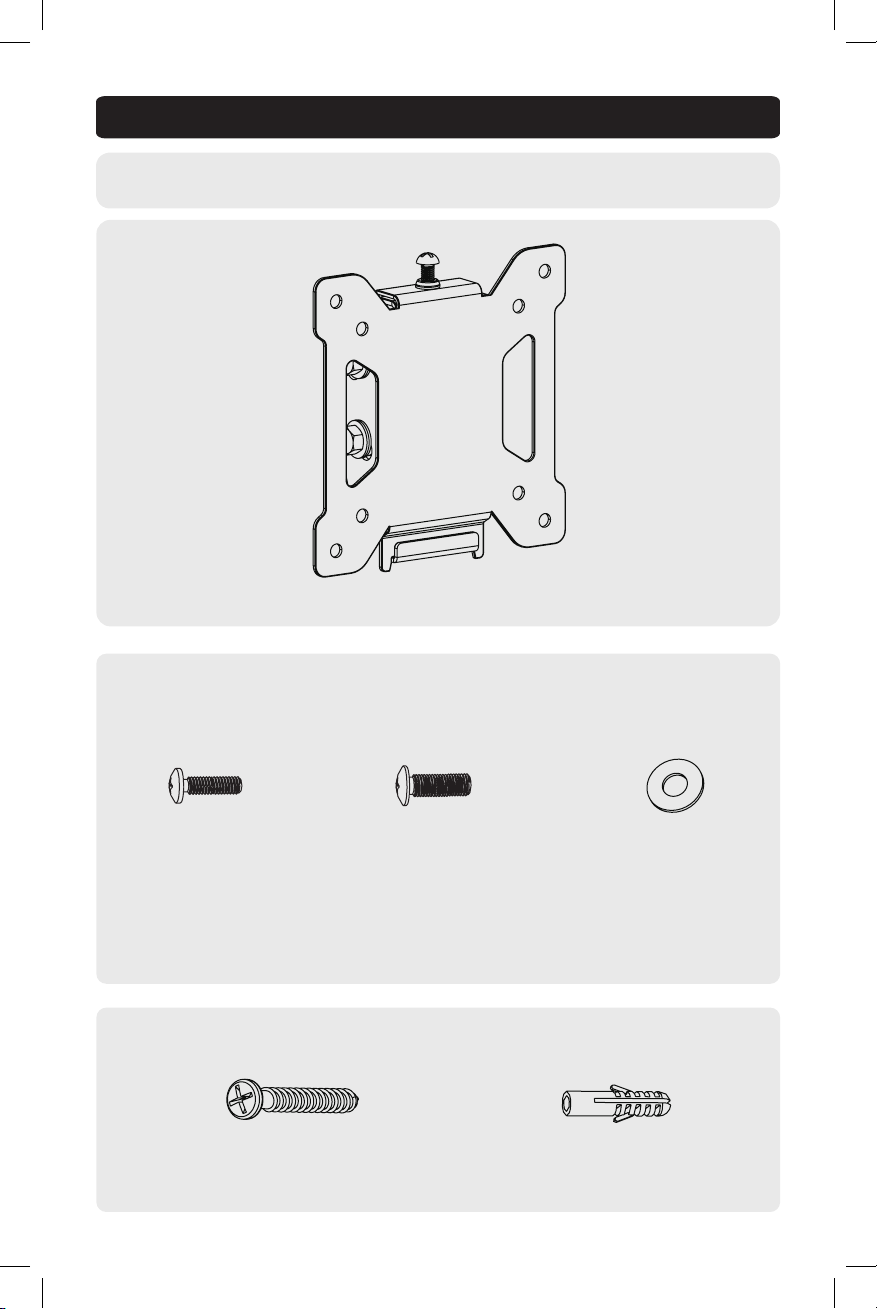
Component Checklist
IMPORTANT: Ensure that you have received all parts according to the component checklist prior to
installing. If any parts are missing or faulty, visit www.tripplite.com/support for service.
DWT1323S
Package M
M4X14 (x4)
M5X14 (x4) D5 washer (x4)
Package W
Anchor Bolt (x2) Concrete Anchor (x2)
3
13-09-229-93-32A5-EN.indd 3 10/31/2013 9:59:04 AM
Page 4

1.Disassemble VESA Plate
2a. Mount on Wood Stud Wall
Use a screwdriver to loosen the
bottom screws in order to separate
the VESA plate from the wall mount.
1
Find and mark the
Anchor Bolt
5mm-8mm
Tighten the screw spacing
5mm-8mm to wall plate.
2
exact location of
mounting holes
3
Drill pilot holes
Screw the wall
mount onto
the wall
WARNING
• Make sure that mounting screws are anchored into the center of the studs.
Use of a stud finder is highly recommended.
• Installers are responsible to provide hardware for other types of mounting situations.
• Installers must verify that the supporting surface will safely support the combined
load of the equipment and all attached hardware and components.
4
13-09-229-93-32A5-EN.indd 4 10/31/2013 9:59:04 AM
Page 5

2b. Mount on Solid Brick and Concrete Block
1
Mark the exact
location of
mounting holes
2
Concrete Anchor
Anchor Bolt
5mm-8mm
Tighten the screw spacing
5mm-8mm to wall plate.
Drill pilot holes
Screw the wall
mount onto
the wall
WARNING
• When installing wall mounts on cinder block, verify the actual concrete thickness
is at least 1-3/8” (35mm) for using the concrete anchors. Do not drill into mortar
joints! Be sure to mount in a solid part of the block, generally 1” (25mm) minimum
from the side of the block. It is suggested an electric drill on a slow setting be used
to drill the hole instead of a hammer drill to avoid breaking out the back of the hole
when entering a void or cavity.
• Installers must verify that the supporting surface will safely support the combined
load of the equipment and all attached hardware and components.
5
13-09-229-93-32A5-EN.indd 5 10/31/2013 9:59:06 AM
Page 6

3. Install the Wall Plate
(For clarit, outer cover is not shown.)
Align top hole of wall plate to screw in
wall and lower the wall plate until the
screw is seated in upper area of tear-drop
mounting hole.
Anchor Bolt
Install the other screw and level the wall
plate, then tighten all screws securely.
6
13-09-229-93-32A5-EN.indd 6 10/31/2013 9:59:09 AM
Page 7

4. Install the VESA Plate
Top of display
TV
Tighten all screws but do not over tighten.
TV
Screw VESA plate onto the display.
TV
D5 Washer
M4X14
M5X14
or
D5 Washer
M4X14
M5X14
7
13-09-229-93-32A5-EN.indd 7 10/31/2013 9:59:09 AM
Page 8

5. Hang the display onto the Wall Plate
Wall
Hook the VESA plate (attached the display) onto the wall
plate and tighten the screw to secure it.
6. Adjustment
Wall Wall
+10°
-15°
Push or pull from the top or bottom of display to obtain a desired angle.
Maintenance
• Check that the bracket is secure and safe to use at regular intervals(at least every three months).
• Please visit www.tripplite.com/support if you have any questions.
1111 W. 35th Street, Chicago, IL 60609 USA • www.tripplite.com/support
8
13-09-229-93-32A5-EN.indd 8 10/31/2013 9:59:09 AM
13-09-229 93-32A5_RevA
 Loading...