

Page 1
Owner’s Manual
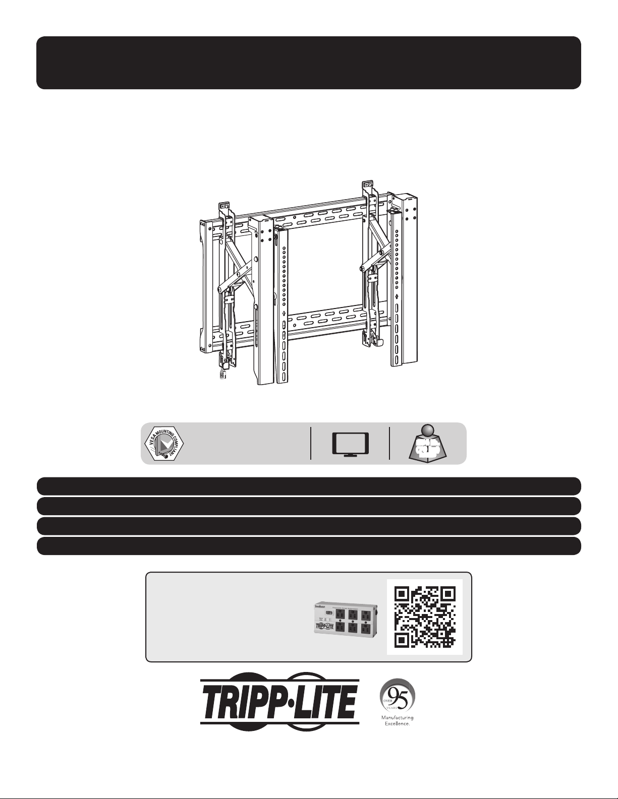
Pop-Out Video Wall
Model: DMVWSC4570XUL
For additional instructions on installing more than one video mount, visit www.tripplite.com.
200x200 / 300x200 / 300x300
400x200 / 400x300 / 400x400
600x400
Este manual esta disponible en español en la página de Tripp Lite: www.tripplite.com
Ce manuel est disponible en français sur le site Web de Tripp Lite : www.tripplite.com
Русскоязычная версия настоящего руководства представлена на веб-сайте компании Tripp Lite по адресу: www.tripplite.com
Dieses Handbuch ist in deutscher Sprache auf der Tripp Lite-Website verfügbar: www.tripplite.com
70"
MAX
154 lb.
(70 kg)
RATED
WARRANTY REGISTRATION
Register your product today and be
automatically entered to win an ISOBAR
surge protector in our monthly drawing!
www.tripplite.com/warranty
1111 W. 35th Street, Chicago, IL 60609 USA • www.tripplite.com/support
Copyright © 2019 Tripp Lite. All rights reserved.
1
Page 2

NOTE: Read the entire instruction manual before you start assembly and installation.
WARNING
• Do not begin the installation until you have read and understood the instructions and warnings contained in this manual.
If you have any questions regarding any of the instructions or warnings, please visit www.tripplite.com/support
• This product was designed to be installed and utilized ONLY as specified in this manual. Improper installation of this product
may cause damage or serious injury.
• This product should only be installed by someone of good mechanical ability, with basic building experience and a full
understanding of this instruction manual.
• Make sure that the unit can safely support the combined load of the equipment and all attached hardware and components.
• Always use an assistant or mechanical lifting equipment to safely lift and position equipment.
• This product is intended for indoor use only. Using this product outdoors could lead to product failure and personal injury.
Warranty and Product Registration
5-Year Limited Warranty
Seller warrants this product, if used in accordance with all applicable instructions, to be free from original defects in material and workmanship for a period of 5 years from the date
of initial purchase. If the product should prove defective in material or workmanship within that period, Seller will repair or replace the product, in its sole discretion.
THIS WARRANTY DOES NOT APPLY TO NORMAL WEAR OR TO DAMAGE RESULTING FROM ACCIDENT, MISUSE, ABUSE OR NEGLECT. SELLER MAKES NO EXPRESS WARRANTIES
OTHER THAN THE WARRANTY EXPRESSLY SET FORTH HEREIN. EXCEPT TO THE EXTENT PROHIBITED BY APPLICABLE LAW, ALL IMPLIED WARRANTIES, INCLUDING ALL WARRANTIES
OF MERCHANTABILITY OR FITNESS, ARE LIMITED IN DURATION TO THE WARRANTY PERIOD SET FORTH ABOVE; AND THIS WARRANTY EXPRESSLY EXCLUDES ALL INCIDENTAL AND
CONSEQUENTIAL DAMAGES. (Some states do not allow limitations on how long an implied warranty lasts, and some states do not allow the exclusion or limitation of incidental or
consequential damages, so the above limitations or exclusions may not apply to you. This warranty gives you specific legal rights, and you may have other rights which vary from
jurisdiction to jurisdiction).
WARNING: The individual user should take care to determine prior to use whether this device is suitable, adequate or safe for the use intended. Since individual applications are
subject to great variation, the manufacturer makes no representation or warranty as to the suitability or fitness of these devices for any specific application.
PRODUCT REGISTRATION
Visit www.tripplite.com/warranty today to register your new Tripp Lite product. You’ll be automatically entered into a drawing for a chance to win a FREE Tripp Lite product!*
* No purchase necessary. Void where prohibited. Some restrictions apply. See website for details.
Tripp Lite has a policy of continuous improvement. Specifications are subject to change without notice. Photos and illustrations may differ slightly from actual products.
2
Page 3
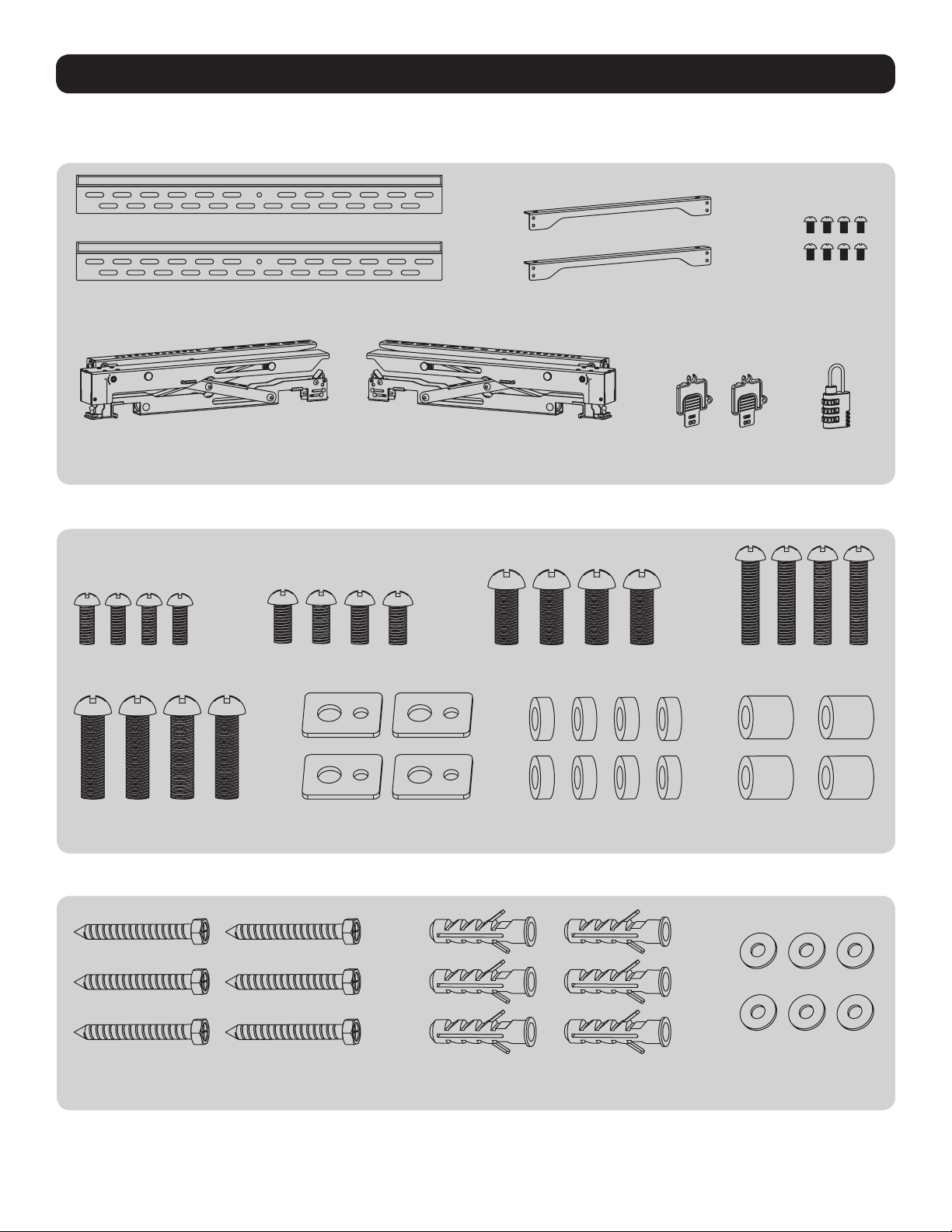
Component Checklist
IMPORTANT: Ensure that you have received all parts according to the component checklist prior to installing. If any parts are
missing or faulty, visit www.tripplite.com/support for service.
Package M
M-A
M5x14
Wall Plate
D
Left Adapter Bracket
A
Right Adapter Bracket
M-B
M6x14
E
M-C
M8x20
B
Connecting Plate
F
Plastic Locks
C
M5x8
G
Combo Lock
M-D
M6x30
Package W
M-E
M8x30
W-A
ST6.3x55
M-F
Washer
Concrete Anchor
3
W-B
M-G
Small Spacer
M-H
Big Spacer
W-C
D6 Washer
Page 4
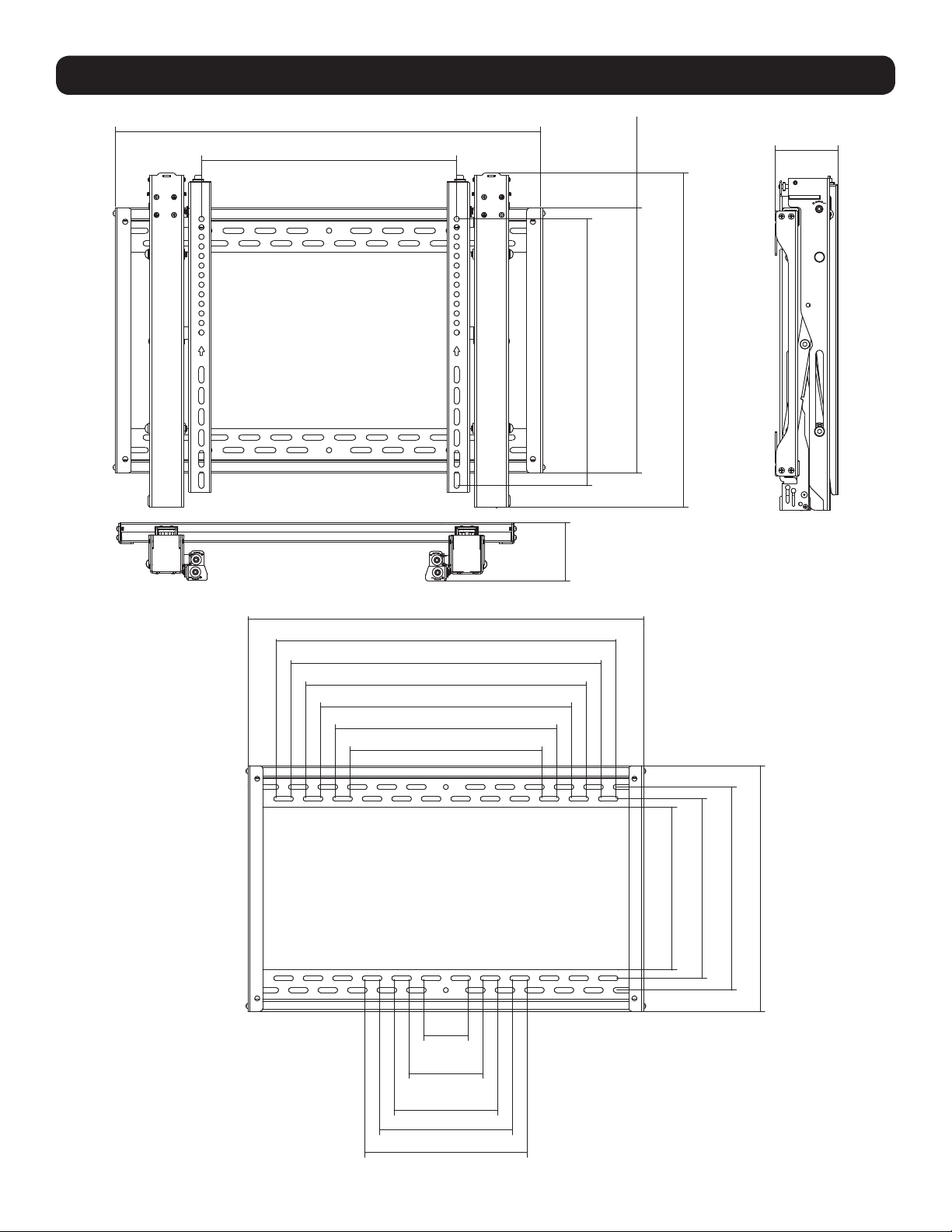
Product Dimensions
26.4 in. (670 mm)
Min: 7.9 in. (200 mm)
Max: 23.6 in. (600 mm)
2.12 in.
(54 mm)
Min: 7.9 in. (200 mm)
3.74 in.
(95 mm)
16.4 in. (416 mm)
Max: 16.5 in. (418 mm)
3.74 in.
(95 mm)
20 in. (524 mm)
26.4 in. (670 mm)
22.6 in. (575 mm)
20.7 in. (525 mm)
18.7 in. (475 mm)
16.7 in. (425 mm)
14.8 in. (375 mm)
12.8 in. (325 mm)
3 in.
(75 mm)
4.9 in.
(125 mm)
6.9 in. (175 mm)
8.9 in. (225 mm)
10.8 in. (275 mm)
12 in. (304 mm)
10.9 in. (276 mm)
13.5 in. (344 mm)
16.4 in. (416 mm)
4
Page 5
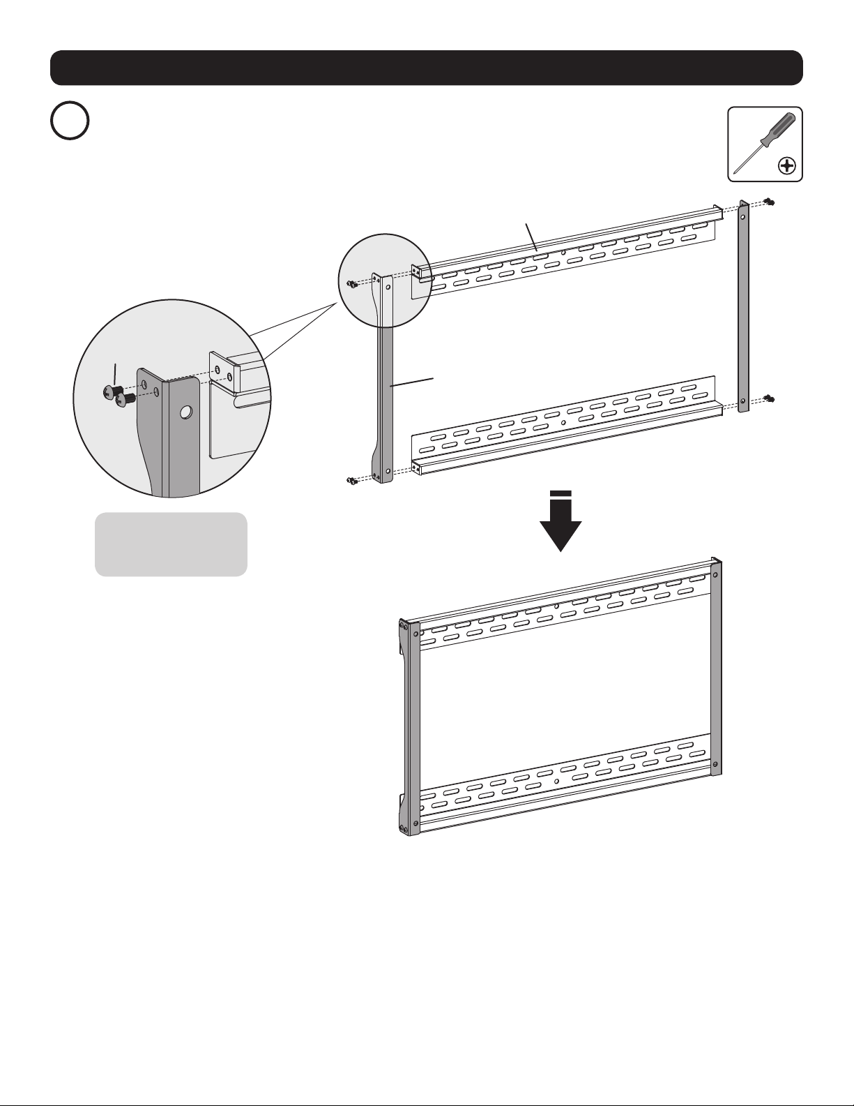
Assembly
Attach Connecting Plates to Wall Plates
1
E
A
B
Using the M5x8 screws
(E), attach the connecting
plates to the wall plates.
5
Page 6

Assembly
Mount on Wood Stud Wall
2a
55 mm
(2.2 in.)
O/ 4.5 mm
O/ (3/16 in.)
Mark the exact location of
mounting holes
Drill pilot
holes
Screw the
wall plate
onto the
wall
W-A
W-C
WARNING
• Make sure that mounting screws are anchored into the center of the studs. Use of a stud finder is highly recommended.
• Installers are responsible to provide hardware for other types of mounting situations.
• Installers must verify that the supporting surface will safely support the combined load of the equipment and all attached
hardware and components.
Using the ST6.3x55 screws (W-A)
and D6 washers (W-C), attach wall
plate assembly to the wall.
6
Page 7

Assembly
Mount on Solid Brick or Concrete Block Wall
2b
60 mm
(2.4 in.)
O/ 10 mm
O/ (3/8 in.)
W-B
W-C
W-A
Mark the exact
location of
mounting holes
Using the ST6.3x55 screws (W-A), D6
washers (W-C) and concrete anchors (W-B),
attach wall plate assembly to the wall.
Drill pilot
holes
Screw the
wall plate
onto the
wall
WARNING
• When installing wall mounts onto a concrete masonry unit (also known as a CMU or “cinder block”), verify that the actual
concrete thickness is at least 35 mm (1-3/8”) in order to hold the concrete anchors. DO NOT DRILL INTO MORTAR JOINTS!
Be sure to mount the assembled wall-mount plate with the included concrete anchors, washers and anchor bolts onto solid
sections of the blocks.
The solid sections can generally be found 25 mm (1”) toward the middle of the block from either end. An electric drill on a
slow setting is suggested to drill the hole rather than a hammer drill so as to avoid breaking out the back of the hole when
entering a hollow section.
• Installers must verify that the supporting surface will safely support the combined load of the equipment and all attached
hardware and components.
7
Page 8

Assembly
Install the Pop-Out Adapter Brackets
3
Hex Key
Ball Joint
Remove the hex
key from the
adapter brackets.
Push the pop-out arm until the ball joint snaps
into place.
Note: Make sure the arrow is pointing up.
D DCC
For VESA 600x400 mounting patterns, the “D” and “C” positions are flipped.
VESA 600x400
Top of the
display.
Top of the
display.
8
Page 9

Assembly
For Flat Back Screens
3a
M-A / M-B / M-C
M-F
Note: Choose appropriate screws according to the type of screen.
• Firmly secure the adapter brackets onto the display using the screws and any other necessary hardware components included with the
unit.
Do not over-tighten screws.
9
Page 10

Assembly
For Bump-Out Screen, Recessed Back Screen
3b
or to Access A/V Inputs
M-C M-C / M-D / M-E M-D / M-E M-D / M-E
or or or
M-G
M-F M-F
Note: Choose appropriate screws, washers and spacers (if necessary) according to the type of screen.
• Firmly secure the adapter brackets onto the display using the screws and any other necessary hardware components included with the
unit.
Do not over-tighten screws.
M-G
M-G
M-F
M-H
M-F
M-H
10
Page 11

Assembly
Attach the Display onto the Wall Plate
4
Locking Plate
G
Turn the locking plates downward to fasten the
wall plate. Tighten the screws to secure.
Adjustment
5
For fast alignment, push
the display to the left or
right.
Micro Adjustment
5a
Use a padlock to
prevent the display
from tampering or
theft.
11
For tilt adjustment.
For in/out micro
adjustment.
For up/down micro
adjustment.
Page 12

Assembly
Tilt Adjustment
5b
1
2
12
Page 13

Assembly
Height Adjustment
5c
1
2
3
4
13
Page 14

Assembly
Depth Adjustment
5d
1
Note: Only use the long end of the hex key
when tightening the adjustment screws.
2
3 4
14
Page 15

Assembly
Secure and Lock the Display
6
Use the plastic locks (F) to
lock the display in place.
• Check that the bracket is secure and safe to use at regular intervals (at least every three months).
• Please visit www.tripplite.com/support if you have any questions.
F
15
Page 16

1111 W. 35th Street, Chicago, IL 60609 USA • www.tripplite.com/support
16
LVW06-46T
19-02-229 93-3944_RevA
 Loading...