

Page 1
Owner’s Manual
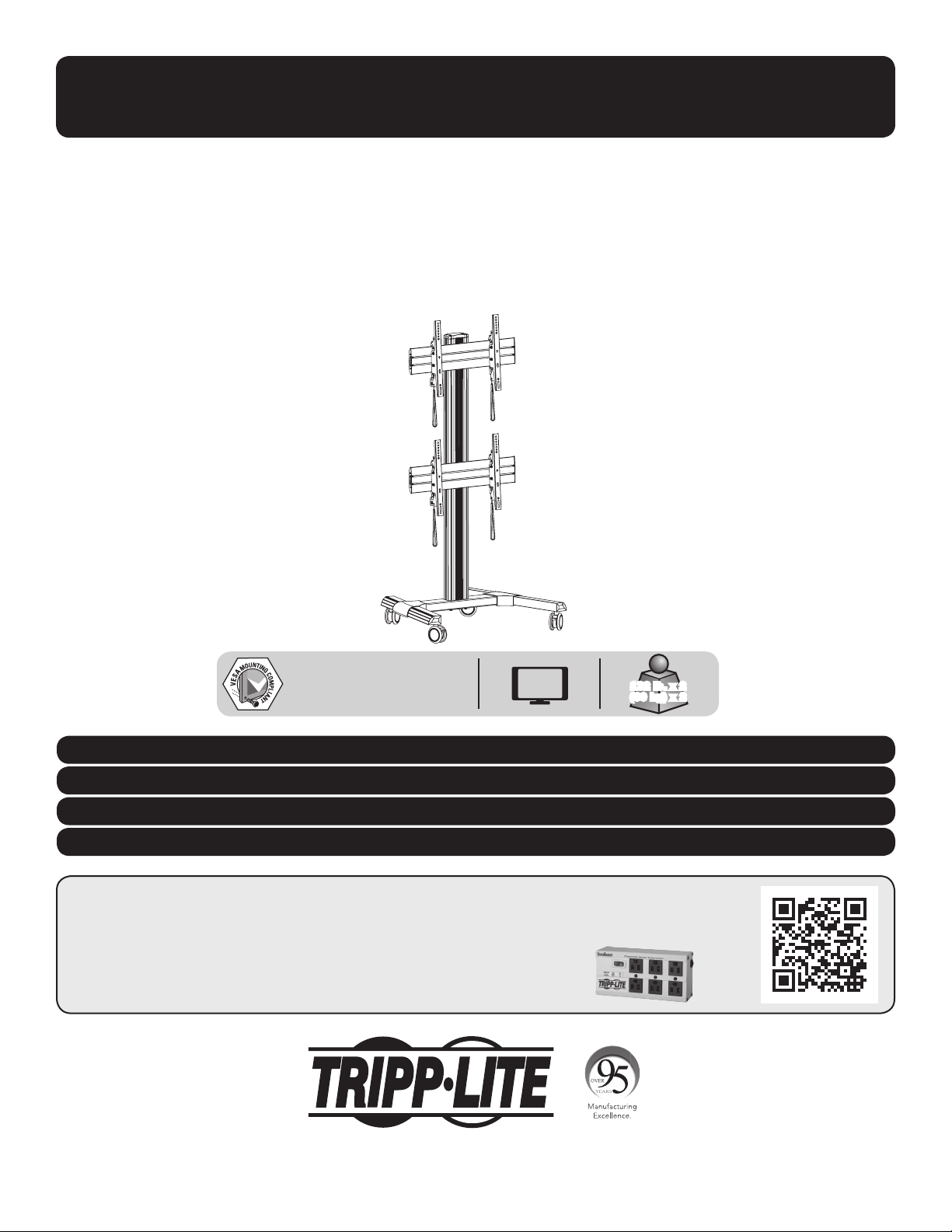
Heavy-Duty
Dual-Monitor Mobile Video Wall
Model: DMCVW4555X2
200x200 / 300x300 / 400x200
400x400 / 600x400
Este manual esta disponible en español en la página de Tripp Lite: www.tripplite.com
Ce manuel est disponible en français sur le site Web de Tripp Lite : www.tripplite.com
Русскоязычная версия настоящего руководства представлена на веб-сайте компании Tripp Lite по адресу: www.tripplite.com
Dieses Handbuch ist in deutscher Sprache auf der Tripp Lite-Website verfügbar: www.tripplite.com
55"
MAX
132 lb. x 2
(60 kg) x 2
PROTECT YOUR INVESTMENT!
Register your product for quicker service and ultimate peace of mind.
You could also win an ISOBAR6ULTRA surge protector—a $100 value!
www.tripplite.com/warranty
1111 W. 35th Street, Chicago, IL 60609 USA • www.tripplite.com/support
Copyright © 2019 Tripp Lite. All rights reserved.
1
Page 2

NOTE: Read the entire instruction manual before you start assembly and installation.
WARNING
• Do not begin the installation until you have read and understood the instructions and warnings contained in this manual. If
you have questions regarding any of the instructions or warnings, please visit www.tripplite.com/support.
• This product was designed to be installed and utilized ONLY as specified in this manual. Improper installation of this product
may cause damage or serious injury.
• This product should only be installed by someone of good mechanical ability, with basic building experience and a full
understanding of this instruction manual.
• Make sure the unit can safely support the combined load of the equipment and all attached hardware and components.
• Always use an assistant or mechanical lifting equipment to safely lift and position equipment.
• This product is intended for indoor use only. Using this product outdoors could lead to product failure and/or personal injury.
Warranty and Product Registration
5-Year Limited Warranty
Seller warrants this product, if used in accordance with all applicable instructions, to be free from original defects in material and workmanship for a period of 5 years from the date
of initial purchase. If the product should prove defective in material or workmanship within that period, Seller will repair or replace the product, in its sole discretion.
THIS WARRANTY DOES NOT APPLY TO NORMAL WEAR OR TO DAMAGE RESULTING FROM ACCIDENT, MISUSE, ABUSE OR NEGLECT. SELLER MAKES NO EXPRESS WARRANTIES
OTHER THAN THE WARRANTY EXPRESSLY SET FORTH HEREIN. EXCEPT TO THE EXTENT PROHIBITED BY APPLICABLE LAW, ALL IMPLIED WARRANTIES, INCLUDING ALL WARRANTIES
OF MERCHANTABILITY OR FITNESS, ARE LIMITED IN DURATION TO THE WARRANTY PERIOD SET FORTH ABOVE; AND THIS WARRANTY EXPRESSLY EXCLUDES ALL INCIDENTAL AND
CONSEQUENTIAL DAMAGES. (Some states do not allow limitations on how long an implied warranty lasts, and some states do not allow the exclusion or limitation of incidental or
consequential damages, so the above limitations or exclusions may not apply to you. This warranty gives you specific legal rights, and you may have other rights which vary from
jurisdiction to jurisdiction).
WARNING: The individual user should take care to determine prior to use whether this device is suitable, adequate or safe for the use intended. Since individual applications are
subject to great variation, the manufacturer makes no representation or warranty as to the suitability or fitness of these devices for any specific application.
PRODUCT REGISTRATION
Visit www.tripplite.com/warranty today to register your new Tripp Lite product. You’ll be automatically entered into a drawing for a chance to win a FREE Tripp Lite product!*
* No purchase necessary. Void where prohibited. Some restrictions apply. See website for details.
Tripp Lite has a policy of continuous improvement. Specifications are subject to change without notice. Photos and illustrations may differ slightly from actual products.
2
Page 3
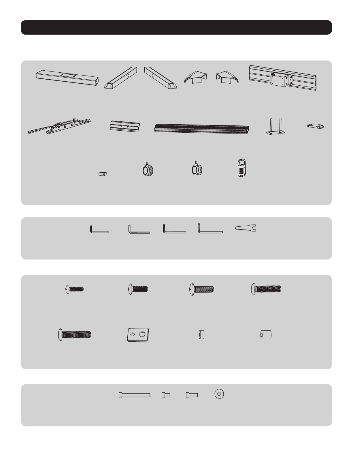
Component Checklist
IMPORTANT: Ensure you have received all parts according to the component checklist prior to installing. If any parts are missing
or faulty, visit www.tripplite.com/support for service.
Adapter Bracket
Package A
A
Middle Base
(x1)
G
(x4)
Connecting Fitting
L
Cable Clamp
(x8)
A-A
3 mm Hex Key
(x1)
B
Left Base
(x1)
H
(x2)
M
Caster Wheel with Brake
(x2)
A-B
4 mm Hex Key
(x1)
C
Right Base
(x1)
5 mm Hex Key
A-C
(x1)
D
Left Cover
(x1)
I
Column
(x1)
N
Caster Wheel
(x2)
A-D
6 mm Hex Key
(x1)
E
Right Cover
(x1)
Combo Lock
O
(x2)
A-E
Wrench
(x1)
F
Universal Plate
(x2)
J
Connecting Piece
(x1)
K
Top Cover
(x1)
Package M
Package P
M-A
M5x14
(x8)
M-E
M8x30
(x8)
M-B
M6x14
(x8)
M-F
Washer
(x8)
P-A
M8x65
(x8)
P-B
M8x16
(x4)
M-C
M8x20
(x8)
M-G
Small Spacer
(x16)
P-C
M8x35
(x4)
M-D
M6x30
(x8)
M-H
Big Spacer
(x8)
P-D
D8 Washer
(x4)
3
Page 4
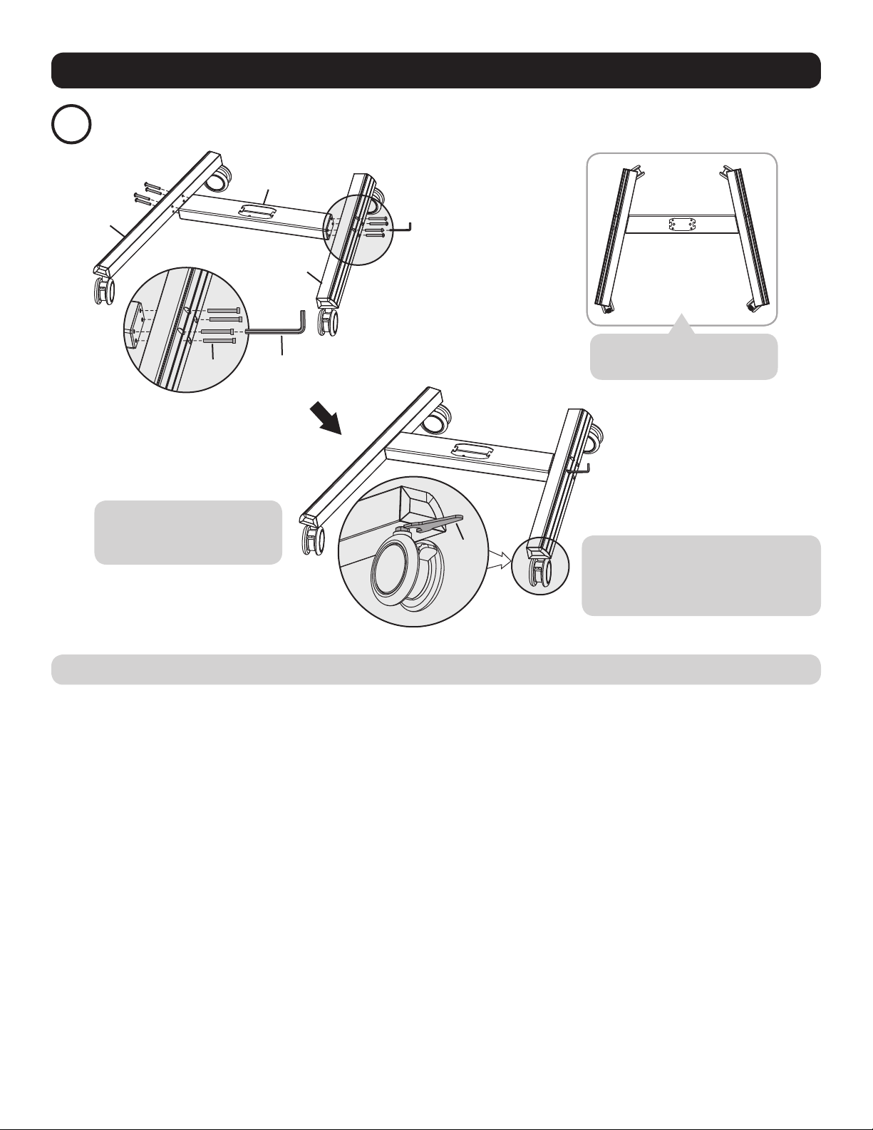
Assembly
Assemble the Base
1
B
P-A
A
A-D
C
Note: Position base assembly
with wheels facing forward.
Note: Lock the brakes on the
casters to avoid any sudden
movements during installation.
Using M8x65 screws (P-A) and the 6 mm hex key (A-D), attach the left and right base to the middle base.
A-E
Each caster can be adjusted
independently for fine tuning. Using the
wrench (A-E), slightly turn each caster
nut to lower or raise the base.
4
Page 5

Assembly
Attach the Columns to the Base
2
P-D
J
A-D
Insert the connecting piece (J) into the column to attach the column to the base. Use M8x35 screws (P-C), D8 washers (P-D) and the
6 mm hex key (A-D) to secure the connecting piece and column to the base.
P-C
Install the Covers
3
E
D
Attach the left cover (D) and right cover (E) to the base.
5
Page 6

Assembly
Install the Universal Plates
4
Slide the
first universal
plate onto the
column, making
sure the arrow
on the universal
plate is pointing
up.
F
Slide the second
universal plate onto
the column, making
sure the arrow is
pointing up.
Allow enough space between
the two universal plates. Set
X + 0.2” (5 mm)
(X=Height of display)
a distance of the height of the
display plus 0.2" (5 mm)
A-C
Once the universal plate positions have been
determined, use the 5 mm hex key (A-C) to secure them
to the column.
6
Page 7

Assembly
Install the Top Cover
5
A-D
Using M8x16 screws (P-B) and the
6 mm hex key (A-D), attach the
top cover (K) to the column.
P-B
K
Install the Adapter Brackets
6
Top of the
display.
7
Page 8

Assembly
Install the
6a
Adapter Brackets
For Flat
Back Screens
Note: Choose appropriate screws and spacers according to the type of screens.
• Position the adapter brackets as close as possible to the center of the display.
• Screw the adapter brackets onto the display.
• Repeat procedure for the second display.
Tighten all screws, but do not over-tighten.
M-A / M-B / M-C
M-F
Install the Adapter Brackets
6b
For Recessed Back Screen or to Access A/V Inputs
M-C
M-C / M-D / M-E M-D / M-E M-D / M-E
M-F
or or or
M-G M-G
M-F
M-F M-F
M-G
M-H M-H
Note: Choose appropriate screws, washers and spacers (if necessary) according to the type of screen.
• Position the adapter brackets as close as possible to the center of the display.
• Screw the adapter brackets onto the display.
• Repeat procedure for the second display.
Tighten all screws, but do not over-tighten.
8
Page 9

Assembly
Attach the Displays onto the Universal Plates
7
Note: When installing the displays, make
sure to work from the bottom universal
plate to the top universal plate.
• Using an assistant or mechanical lifting equipment, carefully lift the display and
pull down the two adapter bracket straps at the same time. Hook the display’s
adapter brackets over the top of the universal wall plate. Release the adapter
bracket straps to secure the display to the universal plate.
• Repeat procedure for the second display.
O
Use the combo locks (O)
to protect the displays
from tampering and theft.
9
Page 10

Assembly
Micro-Adjustment
8
A-C
Note: Adjust the
angle of displays
in the order shown
above.
A-C
If the display tilts upward, adjust using the 5 mm hex key (A-C), as shown above.
A-C
A-C
If the display tilts downward, adjust using the 5 mm hex key (A-C), as shown above.
10
Page 11

Assembly
Micro-Adjustment
8
Up Down
A-C
To move the displays up or down, adjust using the 5 mm hex key (A-C), as shown above.
Note: Make sure to leave a 1 mm gap between the upper and lower displays.
Cable Management
9
1 mm
L
Insert the cable clamps (L) horizontally into the universal plates’ slots, then turn the cable clamps vertically to secure them.
11
Page 12

Assembly
Cable Management
9
Adjustment
10
+3°
–3°
Run the cables
through the cable
clamps and the
column’s rubber strip.
Maintenance
• Check that the bracket is secure and safe to use at regular intervals (at least every three months).
• Please visit www.tripplite.com/support if you have any questions.
1111 W. 35th Street, Chicago, IL 60609 USA • www.tripplite.com/support
12
19-02-169 93-394F_RevA
 Loading...