

Page 1

Owner’s Manual
Console Server Management Switch
Models:
B096-016 / B096-032 / B096-048
Console Server with PowerAlert
Model:
B092-016
Console Server
Models:
B095-004-1E / B095-003-1E-M / B094-008-2E-M-F / B094-008-2E-V
PROTECT YOUR INVESTMENT!
Register your product for quicker service and ultimate peace of mind.
You could also win an ISOBAR6ULTRA surge protector—a $100 value!
www.tripplite.com/warranty
1111 W. 35th Street, Chicago, IL 60609 USA • www.tripplite.com/support
Copyright © 2015 Tripp Lite. All rights reserved. All trademarks are the property of their respective owners.
1
Page 2
FCC Information, Class A
This device complies with part 15 of the FCC Rules. Operation is subject to the following two conditions: (1) This device may
not cause harmful interference, and (2) this device must accept any interference received, including interference that may
cause undesired operation.
Note: This equipment has been tested and found to comply with the limits for a Class A digital device, pursuant to part 15 of
the FCC Rules. These limits are designed to provide reasonable protection against harmful interference when the equipment
is operated in a commercial environment. This equipment generates, uses, and can radiate radio frequency energy and, if
not installed and used in accordance with the instruction manual, may cause harmful interference to radio communications.
Operation of this equipment in a residential area is likely to cause harmful interference in which case the user will be required
to correct the interference at his own expense. The user must use shielded cables and connectors with this equipment. Any
changes or modifications to this equipment not expressly approved by Tripp Lite could void the user’s authority to operate this
equipment.
RoHS
This product is RoHS compliant.
User Notice
All information, documentation and specifications contained in this manual are subject to change without prior notification by
the manufacturer. The manufacturer makes no representations or warranties, either expressed or implied, with respect to the
contents hereof and specifically disclaims any warranties as to merchantability or fitness for any particular purpose. Any of the
manufacturer's software described in this manual is sold or licensed `as is'. Should the programs prove defective following
their purchase, the buyer (and not the manufacturer, its distributor, or its dealer), assumes the entire cost of all necessary
servicing, repair and any incidental or consequential damages resulting from any defect in the software.
The manufacturer of this system is not responsible for any radio and/or TV interference caused by unauthorized modifications
to this device. It is the responsibility of the user to correct such interference. The manufacturer is not responsible for any
damage incurred in the operation of this system if the correct operational voltage setting was not selected prior to operation.
Please take care to follow the safety precautions below when installing and operating the Console Server:
• Do not remove the metal covers. There are no operator-serviceable components inside. Opening or
removing the cover may expose you to dangerous voltage which may cause fire or electric shock. Refer all
service to Tripp Lite qualified personnel
• To avoid electric shock the power cord protective grounding conductor must be connected through to ground
• Always pull on the plug, not the cable, when disconnecting the power cord from the socket
• Do not connect or disconnect the Console Server during an electrical storm
• Also it is recommended you use a surge suppressor or UPS to protect the equipment from transients
Page 3

Table of Contents
Introduction 10
Installation 14
2.1 Models 14
2.1.1 Kit components: B096-048, B096-032 and B096-016 Console Server Management Switch 14
2.1.2 Kit components: B092-016 Console Server with PowerAlert 15
2.1.3 Kit components: B095-004-1E and B095-003-1E-M Console Server 15
2.1.4 Kit components: B094-008-2E-M-F and B094-008-2E-V Console Server 16
2.2 Power Connection 17
2.2.1 Power: Console Server Management Switch 17
2.2.2 Power: Console Server with PowerAlert 17
2.2.3 Power: Console Server 17
2.3 Network Connection 17
2.4 Serial Port Connection 18
2.5 USB Port Connection 18
2.6 Rackmount Console / KVM Connection (B092-016 only) 18
Initial System Configuration 19
3.1 Management Console Connection 19
3.1.1 Connected computer set up 19
3.1.2 Browser connection 20
3.1.3 Initial B092-016 connection 21
3.2 Administrator Password 22
3.2.1 Set up new administrator 23
3.3 Network IP Address 24
3.3.1 IPv6 configuration 25
3.3.2 Dynamic DNS (DDNS) configuration 26
3.4 System Services and Service Access 27
3.4.1 Brute force protection 30
3.5 Communications Software 31
3.5.1 SDT Connector 31
3.5.2 PuTTY 31
3.5.3 SSHTerm 32
3.6 Management Network Configuration 33
3.6.1 Enable the Management LAN 33
3.6.2 Configure the DHCP server 34
3.6.3 Select Failover or broadband OOB 35
3.6.4 Bridging the network ports 35
3.6.5 Wireless LAN 36
3.6.6 Static routes 37
Serial Port, Device & User Configuration 38
4.1 Configuring Serial Ports 38
4.1.1 Common Settings 39
4.1.2 Console Server Mode 40
4.1.3 SDT Mode 44
4.1.4 Device (RPC, UPS, EMD) Mode 44
4.1.5 Terminal Server Mode 44
4.1.6 Serial Bridging Mode 45
4.1.7 Syslog 45
4.2 Add/ Edit Users 46
4.3 Authentication 48
4.4 Network Hosts 48
3
Page 4

Table of Contents
4.5 Trusted Networks 49
4.6 Serial Port Cascading 50
4.6.1 Automatically generate and upload SSH keys 50
4.6.2 Manually generate and upload SSH keys 51
4.6.3 Configure the slaves and their serial ports 52
4.6.4 Managing the slaves 52
4.7 Serial Port Redirection 53
4.7.1 Install VirtualPort client 53
4.7.2 Configure the VirtualPort client 54
4.7.3 To remove a configured port 56
4.7.4 Configure the remote serial device connection 56
4.8 Managed Devices 57
4.9 IPsec VPN 58
4.9.1 Enable the VPN gateway 58
4.10 OpenVPN 60
4.10.1 Enable the OpenVPN 61
4.10.2 Configure as Server or Client 62
4.10.3 Windows OpenVPN Client and Server set up 64
4.11 PPTP VPN 67
4.11.1 Enable the PPTP VPN server 68
4.11.2 Add a PPTP user 69
4.11.3 Set up a remote PPTP client 70
4.12 IP Passthrough 71
4.12.1 Downstream router setup 71
4.12.2 IP Passthrough pre-configuration 71
4.12.3 IP Passthrough configuration 72
4.12.4 Service intercepts 72
4.12.5 IP Passthrough status 72
4.12.6 Caveats 72
Firewall, Failover & Out-of-Band 73
5.1 OoB Dial-In Access 73
5.1.1 Configure dial-in PPP 74
5.1.2 Using SDT Connector client for dial-in 75
5.1.3 Set up Windows XP/2003/Vista/7 client for dial-in 75
5.1.4 Set up earlier Windows clients for dial-in 76
5.1.5 Set up Linux clients for dial-in 76
5.2 OoB Broadband Access 77
5.3 Broadband Ethernet Failover 77
5.4 Dial-Out Access 78
5.4.1 Always-on dial-out 78
5.4.2 Dial-Out Failover 79
5.5 Firewall & Forwarding 80
5.5.1 Configuring network forwarding and IP masquerading 80
5.5.2 Configuring client devices 82
5.5.3 Port/Protocol Forwarding 83
5.5.4 Firewall Rules 84
5.6 Internal Cellular Modem Connection 85
5.6.1 Connecting to a 4G LTE carrier network 85
5.6.2 Verifying the cellular connection 86
5.6.3 Cellular modem watchdog 87
4
Page 5

Table of Contents
5.7 Cellular Operation 88
5.7.1 OOB access set up 88
5.7.2 Cellular failover setup 89
5.7.3 Cellular routing 89
Secure SSH Tunneling & SDT Connector 90
6.1 Configuring for SDT Tunneling to Hosts 91
6.2 SDT Connector Configuration 92
6.2.1 SDT Connector client installation 92
6.2.2 Configuring a new gateway in the SDT Connector client 93
6.2.3 Auto-configure SDT Connector client with the user’s access privileges 94
6.2.4 Make an SDT connection through the gateway to a host 95
6.2.5 Manually adding hosts to the SDT Connector gateway 96
6.2.6 Manually adding new services to the new hosts 97
6.2.7 Adding a client program to be started for the new service 99
6.2.8 Dial-in configuration 100
6.3 SDT Connector to Management Console 101
6.4 SDT Connector - Telnet or SSH Serial Device Connection 102
6.5 SDT Connector OoB Connection 103
6.6 Importing (and Exporting) Preferences 104
6.7 SDT Connector Public Key Authentication 105
6.8 Setting up SDT for Remote Desktop Access 106
6.8.1 Enable Remote Desktop on the target Windows computer to be accessed 106
6.8.2 Configure the Remote Desktop Connection client 107
6.9 SDT SSH Tunnel for VNC 110
6.9.1 Install and configure the VNC Server on the computer to be accessed 110
6.9.2 Install, configure and connect the VNC Viewer 111
6.10 SDT IP Connection to Hosts 113
6.10.1 Establish a PPP connection between the host COM port and Console Server 113
6.10.2 Set up SDT Serial Ports on Console Server 116
6.10.3 Set up SDT Connector to SSH port forward over the Console Server Serial Port 116
6.11 SSH Tunneling using other SSH clients (e.g. PuTTY) 117
Alerts, Automated Response and Logging 120
7.1 Set Up Auto-Response and Configure Check Conditions 120
7.1.1 Environmental Check 121
7.1.2 Alarms and Digital Inputs 122
7.1.3 UPS/Power Supply 122
7.1.4 UPS Status 122
7.1.5 Serial Login/Logout 123
7.1.6 ICMP Ping 123
7.1.7 Cellular Data 123
7.1.8 Custom Check 124
7.1.9 SMS Command 124
7.1.10 Log In/Log Out 125
7.1.11 Network Interface Event 125
7.1.12 Routed data usage check 126
5
Page 6

Table of Contents
7.2 Trigger and Resolve Actions 127
7.2.1 Send Email on Trigger 127
7.2.2 Send SMS on Trigger 127
7.2.3 Perform RPC Action on Trigger 127
7.2.4 Run Custom Script on Trigger 128
7.2.5 Send SNMP Trap on Trigger 128
7.2.6 Send Nagios Event on Trigger 128
7.2.7 Perform Interface Action 128
7.2.8 Resolve Actions 129
7.2.9 Send Email alerts on Resolution 129
7.2.10 Send SMS Alerts on Resolution 129
7.2.11 Send SNMP Trap alerts on Resolution 130
7.2.12 Send Nagios Event alerts on Resolution 131
7.3 Remote Log Storage 132
7.4 Serial Port Logging 132
7.5 Network TCP or UDP Port Logging 133
7.6 Auto-Response Event Logging 133
7.7 Power Device Logging 133
Power and Environment 134
8.1 Remote Power Control (RPC) 134
8.1.1 RPC connection 134
8.1.2 RPC alerts 136
8.1.3 RPC status 136
8.1.4 User power management 137
8.2 Uninterruptible Power Supply Control (UPS) 138
8.2.1 Managed UPS connections 138
8.2.2 Configure UPS powering the Console Server 140
8.2.3 Configuring powered computers to monitor a Managed UPS 141
8.2.4 UPS alerts 142
8.2.5 UPS status 142
8.2.6 Overview of Network UPS Tools (NUT) 143
8.3 Environmental Monitoring 144
8.3.1 Connecting the EMD 145
8.3.2 Environmental alerts 146
8.3.3 Environmental status 146
Authentication 147
9.1 Authentication Configuration 147
9.1.1 Local authentication 147
9.1.2 TACACS authentication 148
9.1.3 RADIUS authentication 149
9.1.4 LDAP authentication 150
9.1.5 RADIUS/TACACS user configuration 152
9.1.6 Group support with remote authentication 152
9.1.7 Remote groups with RADIUS authentication 152
9.1.8 Remote groups with LDAP authentication 154
9.1.9 Idle timeout 155
9.1.10 Kerberos authentication 156
9.1.11 Authentication testing 156
9.2 PAM (Pluggable Authentication Modules) 156
9.3 Secure Management Console Access 157
9.4 SSL Certificate 158
6
Page 7

Table of Contents
Nagios Integration 160
10.1 Nagios Overview 160
10.2 Central management and setting up SDT for Nagios 161
10.2.1 Set up central Nagios server 161
10.2.2 Set up distributed Console Servers 162
10.3 Configuring Nagios distributed monitoring 164
10.3.1 Enable Nagios on the Console Server 164
10.3.2 Enable NRPE monitoring 165
10.3.3 Enable NSCA monitoring 166
10.3.4 Configure selected Serial Ports for Nagios monitoring 167
10.3.5 Configure selected Network Hosts for Nagios monitoring 167
10.3.6 Configure the upstream Nagios monitoring host 168
10.4 Advanced Distributed Monitoring Configuration 169
10.4.1 Sample Nagios configuration 169
10.4.2 Basic Nagios plug-ins 172
10.4.3 Additional plug-ins 172
System Management 173
11.1 System Administration and Reset 173
11.2 Upgrade Firmware 174
11.3 Configure Date and Time 175
11.4 Configuration Backup 176
11.5 Delayed Configuration Commit 177
11.6 FIPS Mode 178
Status Reports 179
12.1 Port Access and Active Users 179
12.2 Statistics 180
12.3 Support Reports 180
12.4 Syslog 181
12.5 Dashboard 181
12.5.1 Configuring the Dashboard 182
12.5.2 Creating custom widgets for the Dashboard 183
Management 184
13.1 Device Management 184
13.2 Port and Host Log Management 185
13.3 Terminal Connection 185
13.3.1 Web Terminal 185
13.3.1.1 Web Terminal to Command Line 185
13.3.1.2 Web Terminal to Serial Device 186
13.3.2 SDTConnector access 186
13.4 Power Management 187
13.5 Remote Console Access (B092-016 only) 187
Command Line Configuration 188
14.1 Accessing config from the command line 188
14.1.1 Serial Port configuration 190
14.1.2 Adding and removing Users 193
14.1.3 Adding and removing user Groups 194
14.1.4 Authentication 195
14.1.5 Network Hosts 196
14.1.6 Trusted Networks 197
14.1.7 Cascaded Ports 197
7
Page 8

Table of Contents
14.1.8 UPS Connections 198
14.1.9 RPC Connections 199
14.1.10 Environmental 200
14.1.11 Managed Devices 200
14.1.12 Port Log 201
14.1.13 Alerts 202
14.1.14 SMTP & SMS 203
14.1.15 SNMP 205
14.1.16 Administration 205
14.1.17 IP settings 205
14.1.18 Date & Time settings 206
14.1.19 Dial-in settings 206
14.1.20 DHCP server 207
14.1.21 Services 208
14.1.22 NAGIOS 208
14.2 General Linux command usage 209
Advanced Configuration 211
15.1 Custom Scripting 211
15.1.1 Custom script to run when booting 211
15.1.2 Running custom scripts when alerts are triggered 212
15.1.3 Example script - Power cycling on pattern match 213
15.1.4 Example script - Multiple email notifications on each alert 213
15.1.5 Deleting configuration values from the CLI 214
15.1.6 Power cycle any device upon a ping request failure 217
15.1.7 Running custom scripts when a configurator is invoked 218
15.1.8 Backing-up the configuration and restoring using a local USB stick 218
15.1.9 Backing-up the configuration off-box 219
15.2 Advanced Portmanager 220
15.2.1 Portmanager commands 220
15.2.2 External Scripts and Alerts 223
15.3 Raw Access to Serial Ports 224
15.3.1 Access to serial ports 224
15.3.2 Accessing the console/modem port 224
15.4 IP- Filtering 225
15.5 SNMP Status Reporting and Traps 225
15.5.1 Retrieving status information using SNMP 225
15.5.2 Check firewall rules 225
15.5.3 Enable SNMP service 226
15.5.4 /etc/config/snmpd.conf 229
15.5.5 Adding multiple remote SNMP managers 229
15.6 Secure Shell (SSH) Public Key Authentication 230
15.6.1 SSH Overview 230
15.6.2 Generating Public Keys (Linux) 231
15.6.3 Installing the SSH Public/Private Keys (Clustering) 231
15.6.4 Installing SSH Public Key Authentication (Linux) 232
15.6.5 Generating public/private keys for SSH (Windows) 233
15.6.6 Fingerprinting 234
15.6.7 SSH tunneled serial bridging 235
15.6.8 SDT Connector Public Key Authentication 237
15.7 Secure Sockets Layer (SSL) Support 238
8
Page 9

Table of Contents
15.8 HTTPS 238
15.8.1 Generating an encryption key 238
15.8.2 Generating a self-signed certificate with OpenSSL 238
15.8.3 Installing the key and certificate 239
15.8.4 Launching the HTTPS Server 239
15.9 Power Strip Control 240
15.9.1 PowerMan 240
15.9.2 pmpower 241
15.9.3 Adding new RPC devices 241
15.10 IPMItool 243
15.11 Scripts for Managing Slaves 245
15.12 SMS Server Tools 246
15.13 Multicast 246
15.14 Zero Touch Provisioning 247
15.14.1 Preparation 247
15.14.2 Example ISC DHCP server configuration 247
15.14.3 Setup for an untrusted LAN 247
15.14.4 How it works 248
15.14.5 Setup a USB key for authenticated restore 249
Thin Client (B092-016) 252
16.1 Local Client Service Connections 252
16.1.1 Connect: Serial Terminal 253
16.1.2 Connect: Browser 254
16.1.3 Connect: VNC 255
16.1.4 Connect: SSH 256
16.1.5 Connect: IPMI 257
16.1.6 Connect: Remote Desktop (RDP) 258
16.1.7 Connect: Citrix ICA 259
16.1.8 Connect: PowerAlert 259
16.2 Advanced Control Panel 260
16.2.1 System: Terminal 260
16.2.2 System: Shutdown / Reboot 260
16.2.3 System: Logout 260
16.2.4 Custom 260
16.2.5 Status 260
16.2.6 Logs 260
16.3 Remote Control 261
Appendix A: Hardware Specification 262
Appendix B: Serial Port Connectivity 263
Appendix C: End User License Agreements 265
Appendix D: Service and Warranty 272
9
Page 10

Chapter 1: Introduction
This User Manual is provided to help you get the most from your B096-016 / B096-032 / B096-048 Console Server
Management Switch, B092-016 Console Server with PowerAlert or B095-004-1E / B095-003-1E-M / B094-008-2E-M-F /
B094-008-2E-V Console Server product. These products are referred to generically in this manual as Console Servers.
Once configured, you will be able to use your Console Server to securely monitor, access and control the computers,
networking devices, telecommunications equipment, power supplies and operating environment in your data center, branch
office or communications room. This manual guides you in managing this infrastructure locally (at the rack side or across your
operations or management LAN or through the local serial console port), and remotely (across the Internet, private network or
via dial up).
Manual Organization
This manual contains the following chapters:
1. Introduction An overview of the features of the Console Server and information on this manual
2. Installation Details physical installation of the Console Server and the interconnection of controlled
devices
3. System Configuration Describes the initial installation and configuration using the Management Console of the
Console Server on the network and the services that will be supported
4. Serial and Network Covers configuring serial ports and connected network hosts, and setting up Users and
Groups
5. Failover and OoB dial-in Describes setting up the high-availability access features of the Console Server
6. Secure Tunneling (SDT) Covers secure remote access using SSH and configuring for RDP, VNC, HTTP, HTTPS, etc.
access to network and serially connected devices
7. Alerts and Logging Explains the setting up of local and remote event/ data logs and triggering SNMP and email
alerts
8. Power & Environment Management of USB, serial and network attached Power Distribution units and UPS units
including Network UPS Tool (NUT) operation and IPMI power control. EMD environmental
sensor configuration
9. Authentication All access to the Console Server requires usernames and passwords which are locally or
externally authenticated
10. Nagios Integration Setting Nagios central management with SDT extensions and configuring the Console Server
as a distributed Nagios server
11. System Management Covers access to and configuration of services to be run on the Console Server
12. Status Reports View the status and logs of serial and network connected devices (ports, hosts, power and
environment)
13. Management Includes port controls and reports that can accessed by Users
14. Basic Configuration Command line installation and configuration using the config command
15. Advanced Config More advanced command line configuration activities where you will need to use Linux
commands
16. Thin Client Configuration and use of the thin client and other applications (including PowerAlert)
embedded in the Console Server with PowerAlert (B092-016) product
10
Page 11
Chapter 1: Introduction
Types of users
The Console Server supports two classes of users:
I. Administrative users: Those who will be authorized to configure and control the Console Server; and to access and control
all the connected devices. These administrative users will be set up as members of the admin user group. Any user
in this class is referred to generically in this manual as an Administrator. An Administrator can access and control the
Console Server using the config utility, the Linux command line or the browser-based Management Console. By default
the Administrator has access to all services and ports to control all the serial connected devices and network connected
devices (hosts).
II. Users: Embraces those who have been set up by the Administrator with specific limits on their access and control
authority. These users are set up as members of the user’s user group (or some other user groups the Administrator may
have added). They are only authorized to perform specified controls on specific connected devices and are referred to as
Users. These Users (when authorized) can access serial or network connected devices; and control these devices using
the specified services (e.g. Telnet, HHTPS, RDP, IPMI, Serial over LAN, Power Control). An authorized User can also use the
Management Console to access configured devices and review port logs.
In this manual, when the term user (lower case) is used, it is referring to both the above classes of users. This document
also uses the term remote users to describe users who are not on the same LAN segment as the Console Server. These
remote users may be Users, who are on the road connecting to managed devices over the public Internet, or it may be an
Administrator in another office connecting to the Console Server itself over the enterprise VPN, or the remote user may be in
the same room or the same office but connected on a separate VLAN to the Console Server.
Management Console
The Console Server Management Console runs in a browser. It provides a view of your Console Server Management Switch
(B096-016/032/048), Console Server with PowerAlert (B092-016) or Console Server (B095-004/003 and
B094-008-2E-M-F / B094-008-2E-V) product and all the connected equipment.
Administrators can use the Management Console, either locally or from a remote location, to configure the Console Server, set
up Users, configure the ports and connected hosts, and set up logging and alerts.
An authorized User can use the Management Console to access and control configured devices, review port logs, use the
in-built Web terminal to access serially attached consoles and control power to connected devices.
11
Page 12
Chapter 1: Introduction
The Console Server runs an embedded Linux operating system. Experienced Linux and UNIX users may prefer to undertake
configuration at the command line. As an Administrator you can get command line access by connecting through a terminal
emulator or communications program to the console serial port; or by SSH or Telnet connecting to the Console Server over the
LAN; or by connecting to the Console Server through an SSH tunnel using the SDTConnector.
The B092-016 Console Server also has PowerAlert software and a selection of thin clients embedded (RDP, Firefox etc). You
will be able to use these consoles as well as the standard Management Console for access and control.
Manual Conventions
This manual uses different fonts and typefaces to show specific actions:
Note: Text presented like this indicates issues to take note of.
Text presented like this highlights important issues and it is essential you read and take head of these warnings.
• Text presented with a bullet point indent indicates an action you should take as part of the procedure.
Bold text indicates text that you type, or the name of a screen object (e.g. a menu or button) on the Management Console.
Italic text is also used to indicate a text command to be entered at the command line level.
12
Page 13

Chapter 1: Introduction
Publishing history
Date Revision Update details
January 2009 0.9 Initial draft
February 2009 0.91 Pre-release
January 2010 1.01 Add B095-004/003 Console Server and Firmware 3.0.1 features
January 2011 2.0 Firmware 3.3.2 features
March 2011 2.0.1 Support for additional USB ports and 16GB internal flash in B096-016 /
B096-032 / B096-048
February 2012 2.0.02 Add B094-008-2E-M-F and 3.5.2 firmware features
September 2013 2.0.3 Firmware 3.8.1 features
October 2014 2.0.4 Add B094-008-2E-V and 3.11.2 firmware features
December 2014 2.0.5 Firmware 3.11.4 features
April 2015 2.0.6 Firmware 3.15.1 features
13
Page 14

Chapter 2: Installation
This chapter describes the physical installation of the Console Server hardware and connection to controlled devices
2.1 Models
There are a number of Console Server models, each with a different number of network, USB and serial ports and power
supplies:
Console Server Model Serial Ports Network Ports Console Port USB Port Modem Power
B096-048 48 2 1 1+2 Internal Dual AC Universal Input
B096-032 32 2 1 1+2 Internal Dual AC Universal Input
B096-016 16 2 1 1+2 Internal Dual AC Universal Input
B092-016 16 1 1+KVM 4 - Single AC Universal Input
B095-004-1E 4 1 1 1 - External DC Supply
B095-003-1E-M 3 1 1 1 Internal External DC Supply
B094-008-2E-M-F 8 2 1 2 Internal External DC Supply
B094-008-2E-V 8 2 1 2 Internal
Cellular
2.1.1 Kit components: B096-048, B096-032 and B096-016 Console Server Management Switch
B096-048, B096-032 or B096-016
Console Server Management Switch
External DC Supply
2 x Cable UTP Cat5 blue
Connectors
DB9F-RJ45S straight and cross-over
Dual IEC AC power cords
Quick Start Guide and CD-ROM
• Unpack your Console Server Management Switch kit and verify you have all the parts shown above, and that they all
appear in good working order
• If you are installing your Console Server Management Switch in a rack you will need to attach the rack mounting brackets
supplied with the unit, and install the unit in the rack. Take care to head the Safety Precautions
• Connect your Console Server Management Switch to the network, to the serial ports of the controlled devices, and to
power as outlined below
14
Page 15

Chapter 2: Installation
2.1.2 Kit components: B092-016 Console Server with PowerAlert
B092-016
Console Server with PowerAlert
2 x Cable UTP Cat5 blue
Connector
DB9F-RJ45S straight and DB9F-RJ45S cross-over
AC power cable
Quick Start Guide and CD-ROM
• Unpack your Console Server and verify you have all the parts shown above, and that they all appear in good working order
• If you are installing your Console Server in a rack, you will need to attach the rack mounting brackets supplied with the
unit, and install the unit in the rack. Take care to heed the Safety Precautions listed earlier
• Proceed to connect your B092-016 to the network, to the serial and USB ports of the controlled devices, to any rack side
LCD console or KVM switch, and to power as outlined below
2.1.3 Kit components: B095-004-1E and B095-003-1E-M Console Server
B095-004-1E 4-port Console Server with single NIC or B095-003-1E-M 3- port Console
Server with single NIC and modem
2 x Cable UTP Cat5 blue
Connectors
DB9F-RJ45S straight and cross-over
External power supply
Quick Start Guide and CD-ROM
• Unpack your Console Server kit and verify you have all the parts shown above, and that they all appear in good working
order
• If you are installing your Console Server in a rack you will need to attach the rack mounting brackets supplied with the
unit, and install the unit in the rack. Take care to head the Safety Precautions
• Proceed to connect your Console Server to the network, to the serial ports of the controlled devices, and to power as
outlined below
15
Page 16

Chapter 2: Installation
2.1.4 Kit components: B094-008-2E-M-F and B094-008-2E-V Console Server
B094-008-2E-M-F 8- port Console Server with dual NIC and modem or B094-008-2E-V 8 -port
Console Server with dual NIC and cellular
2 x Cable UTP Cat5 blue
Connectors
DB9F-RJ45S straight and cross-over
External power supply
Quick Start Guide and CD-ROM
• Unpack your Console Server kit and verify you have all the parts shown above, and they all appear to be in good working order
• If you are installing your Console Server in a rack, you will need to attach the rack mounting brackets supplied with the
unit and install the unit in the rack. Follow the Safety Precautions
• Proceed to connect your Console Server to the network, to the serial ports of the controlled devices, and to power as
outlined below
16
Page 17
Chapter 2: Installation
2.2 Power Connection
2.2.1 Power: Console Server Management Switch
The B096-048/032/016 Console Server Management Switch has dual universal AC power supplies with auto failover built in.
These power supplies each accept AC input voltage between 100 and 240 VAC with a frequency of 50 or 60 Hz and the total
power consumption per Console Server is less than 30W. Two IEC AC power sockets are located at the rear of the metal case,
and these IEC power inlets use conventional IEC AC power cords. A North American power cord is provided by default. Power
cords for other regions are available separately from Tripp Lite.
2.2.2 Power: Console Server with PowerAlert
The standard B092-016 Console Server has a built-in universal auto-switching AC power supply. This power supply accepts AC
input voltage between 100 and 240 VAC with a frequency of 50 or 60 Hz and the power consumption is less than 40W.
The AC power socket is located at the rear of the B092-016. This power inlet uses a conventional AC power cord. A North
American power cord is provided by default. Power cords for other regions are available separately from Tripp Lite.
2.2.3 Power: Console Server
The B095-004/003 and B094-008-2E-M-F / B094-008-2E-V Console Servers each have an external wall-mount power
supply. This power supply accepts AC input voltage between 100 and 240 VAC with a frequency of 50 or 60 Hz and the total
power consumption per console server is less than 20W. The DC power socket on the Console Server is located on the side of
the metal case marked PWR.
2.3 Network Connection
The RJ45 10/100 LAN port is located on the rear of the B092-016 Console Server, on the front of the B096-048/032/016
Console Server Management Switch and on the side panel of the B095-004/003 and B094-008-2E-M-F / B094-008-2E-V
Console Servers. All physical connections are made using industry standard Cat5e patch cables (Tripp Lite N001 and N002
series cables). Ensure you only connect the LAN port to an Ethernet network that supports 10Base-T/100Base-T. For the initial
configuration of the Console Server you must connect a computer to the Console Server’s principal network port.
17
Page 18
Chapter 2: Installation
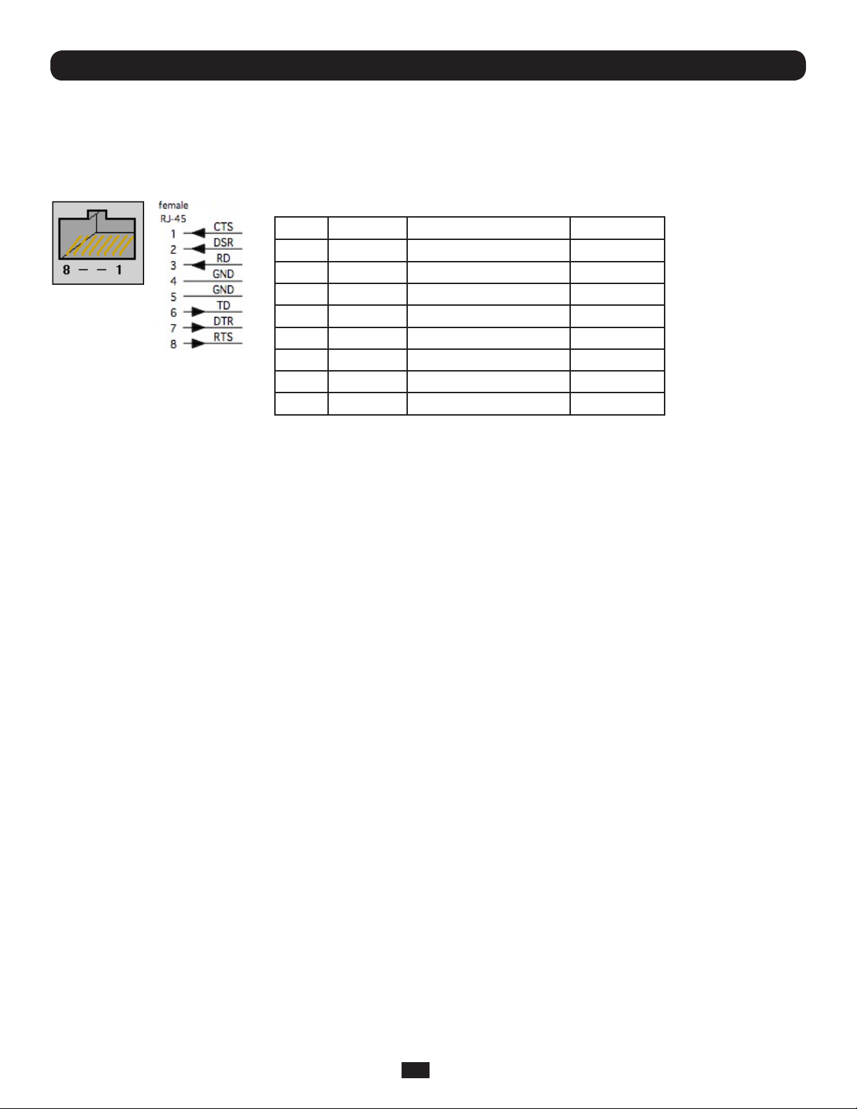
2.4 Serial Port Connection
The RJ45 serial ports are located on the rear of the B092-016 Console Server, on the front of the B096-048/032/016
Console Server and B094-008 Console Server, and on the side panel of the B095-004/003 Console Server. These Console
Servers use the RJ45 pinout used by Cisco. Use straight through RJ-45 cabling to connect to equipment such as Cisco,
Juniper, SUN, and more.
PIN SIGNAL DEFINITION DIRECTION
1 CTS Clear To Send Input
2 DSR Data Set Ready Input
3 RXD Receive Data Input
4 GND Signal Ground NA
5 GND Signal Ground NA
6 TXD Transmit Data Output
7 DTR Data Terminal Ready Output
8 RTS Request To Send Output
Conventional Cat5 cabling with RJ45 jacks are used for serial connections. Before connecting the console port of an external
device to the Console Server serial port, confirm that the device supports standard RS-232C (EIA-232).
The Console Server also has a DB9 LOCAL (Console/Modem) port. This DB-9 connector is on the rear panel of the B092-016
Console Server, and on the front panel of the B096-048/032/016 Console Server Management Switch.
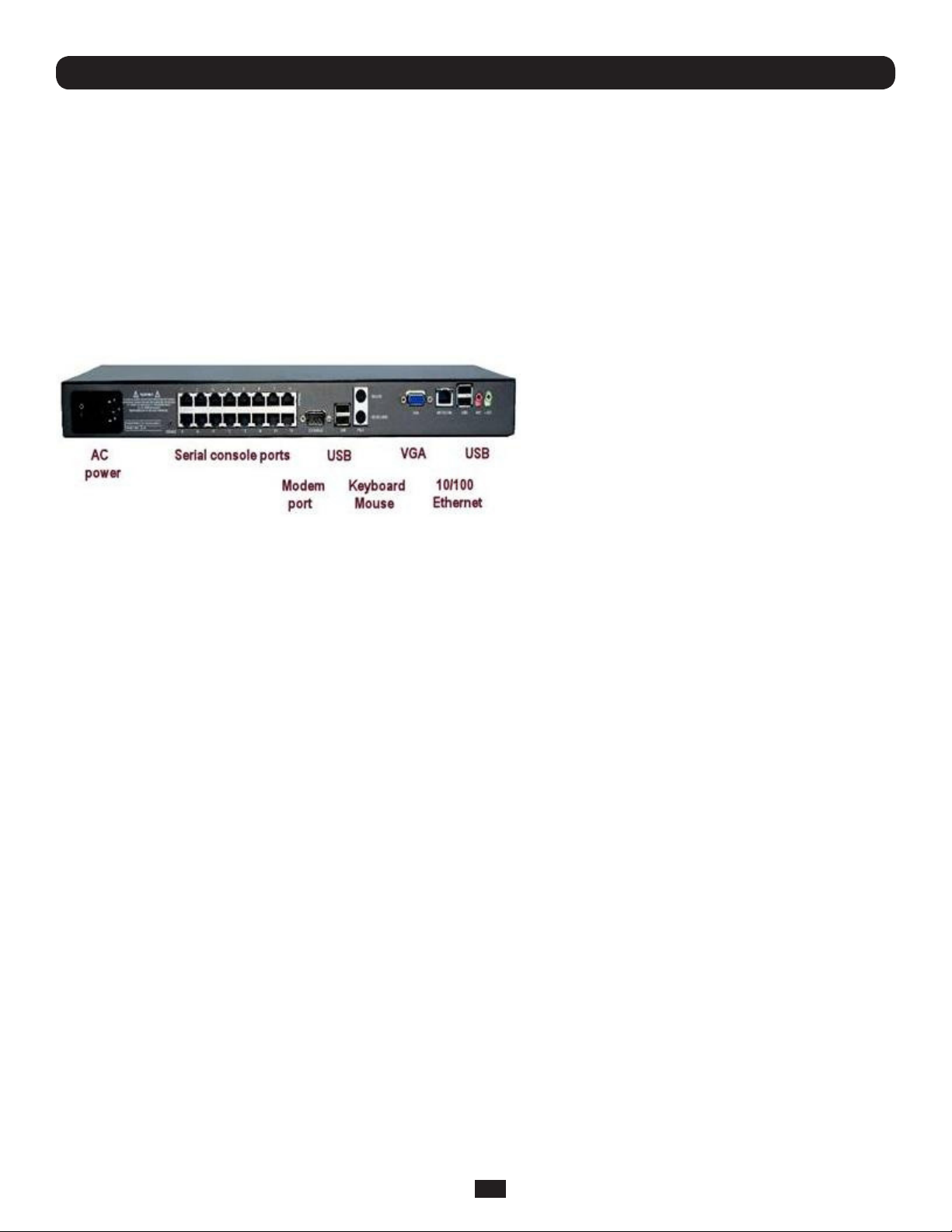
2.5 USB Port Connection
The B096-048/032/016 Console Server Management Switch has one USB 1.0 port on the front panel and two USB 2.0 ports
on the rear. External USB devices can be plugged into these USB ports.
Note: The B096-048/032/016 Console Server Management Switch ships with an internal 16GB USB memory which can be
used for extended log file storage
The B094-008-2E-M-F / B094-008-2E-V Console Server has two USB 2.0 ports on the front. External USB devices can be
plugged into these USB ports.
Note: The B094-008-2E-M-F / B094-008-2E-V Console Server ships with an internal 4GB USB memory which can be used
for extended log file storage
There are four USB 2.0 ports on the rear panel of the B092-016 Console Server and one USB2.0 port located under the RJ45
10/100 LAN connector on the B095-004/003 Console Server. These ports are used to connect to USB consoles (of managed
UPS hardware) and to other external devices (such as a USB memory stick or keyboard).
External USB devices (including USB hubs) can be plugged into any Console Server USB port.
2.6 Rackmount Console / KVM Connection (B092-016 only)
B092-016 Console Server with PowerAlert can be connected directly to a rackmount console (such as B021-000-17
or B021-019 by Tripp Lite) to provide direct local management right at the rack. Connect the rackmount console’s PS/2
Keyboard/Mouse and VGA connectors directly to the PS/2 and VGA connectors on the B092-016. The default video resolution
is 1024 x 768. The B092-016 Console Server also supports the use of a USB keyboard/mouse.
Alternately, the B092-016 Console Server can also be connected locally to a KVM (or KVMoIP) switch at the rack. The B092016 Console Server with PowerAlert will enable you then to use this KVM infrastructure to run PowerAlert, to manage your
power devices and to run the thin clients to manage other devices.
Note: Care should be taken in handling all Console Server products. There are no operator-serviceable components inside, so
do not remove cover. Refer any service to qualified personnel
18
Page 19

Chapter 3: Initial System Configuration
This chapter provides step-by-step instructions for the initial configuration of your Console Server and connecting it to your
management or operational network. This involves the Administrator:
• Activating the Management Console
• Changing the Administrator password
• Setting the IP address for the Console Server’s principal LAN port
• Selecting the network services to be supported
This chapter also discusses the communications software tools that the Administrator may use to access the Console Server. It
also covers the configuration of the additional LAN ports on the B096-016/032/048 Console Server Management Switch.
Note: For guidance on configuring large numbers of appliances and/or automating provisioning, please consult the sections
entitled Bulk Provisioning and Zero Touch Provisioning.
3.1 Management Console Connection
Your Console Server comes configured with a default IP Address 192.168.0.1 Subnet Mask 255.255.255.0
• Directly connect a computer to the Console Server
Note: For initial configuration it is recommended that the Console Server be connected directly to a single PC or computer.
However, if you choose to connect your LAN before completing the initial setup steps, it is important that:
o you ensure there are no other devices on the LAN with an address of 192.168.0.1
o the Console Server and the computer are on the same LAN segment, with no interposed router appliances
3.1.1 Connected computer set up
To configure the Console Server with a browser, the connected computer should have an IP address in the same range as the
Console Server (for example, 192.168.0.100):
• To configure the IP Address of your Linux or Unix computer simply run ifconfig
• For Windows PCs (Win9x/Me/2000/XP/Vista/7/NT):
• Click Start -> (Settings ->) Control Panel and double click Network Connections (for 95/98/Me, double click
Network).
• Right click on Local Area Connection and select Properties.
• Select Internet Protocol (TCP/IP) and click Properties.
• Select Use the following IP address and enter the following details:
o IP address: 192.168.0.100
o Subnet mask: 255.255.255.0
• If you want to retain your existing IP settings for this network connection, click Advanced and Add the above as a
secondary IP connection.
• If it is not convenient to change your computer network address, you can use the ARP-Ping command to reset the Console
Server IP address. To do this from a Windows PC:
• Click Start -> Run (or select All Programs then Accessories then Run).
• Type cmd and click OK to bring up the command line.
• Type arp –d to flush the ARP cache.
• Type arp –a to view the current ARP cache (this should be empty).
19
Page 20
Chapter 3: Initial System Configuration
Now add a static entry to the ARP table and ping the Console Server to assign the IP address to the console server. In the
example below, a Console Server has a MAC Address 00:13:C6:00:02:0F (designated on the label on the bottom of the unit)
and we are setting its IP address to 192.168.100.23. Also the PC/workstation issuing the arp command must be on the same
network segment as the Console Server (that is, have an IP address of 192.168.100.xxx)
• Type arp -s 192.168.100.23 00-13-C6-00-02-0F (Note for UNIX the syntax is: arp -s 192.168.100.23
00:13:C6:00:02:0F).
• Type ping -t 192.18.100.23 to start a continuous ping to the new IP Address.
• Turn on the Console Server and wait for it to configure itself with the new IP address. It will start replying to the ping at
this point.
• Type arp –d to flush the ARP cache again.
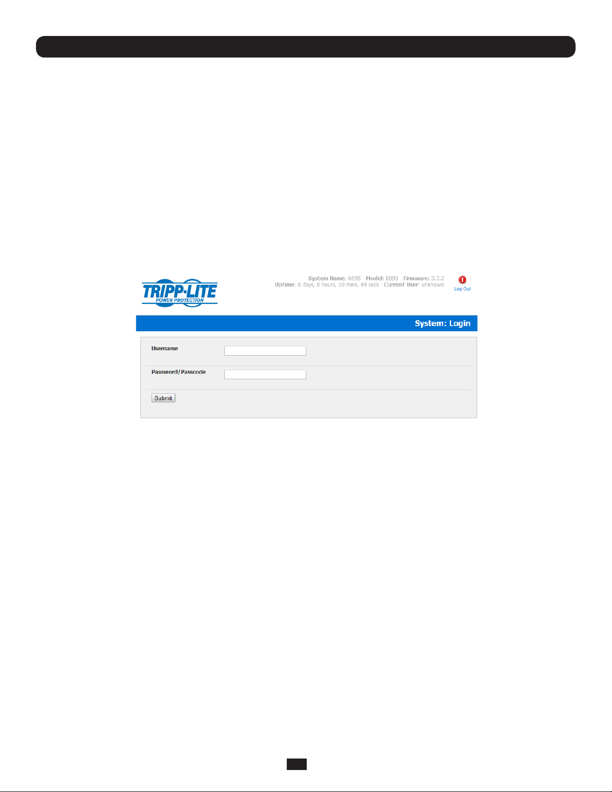
3.1.2 Browser connection
• Activate your preferred browser on the connected computer and enter https://192.168.0.1 The Management Console
supports all current versions of the popular browsers (Internet Explorer, Mozilla Firefox, Google Chrome, Apple Safari and
more)
• You will be prompted to log in. Enter the default administration username and administration password (Username: root
Password: default)
Note: Console Servers are factory configured with HTTPS access enabled and HTTP access disabled.
20
Page 21
Chapter 3: Initial System Configuration
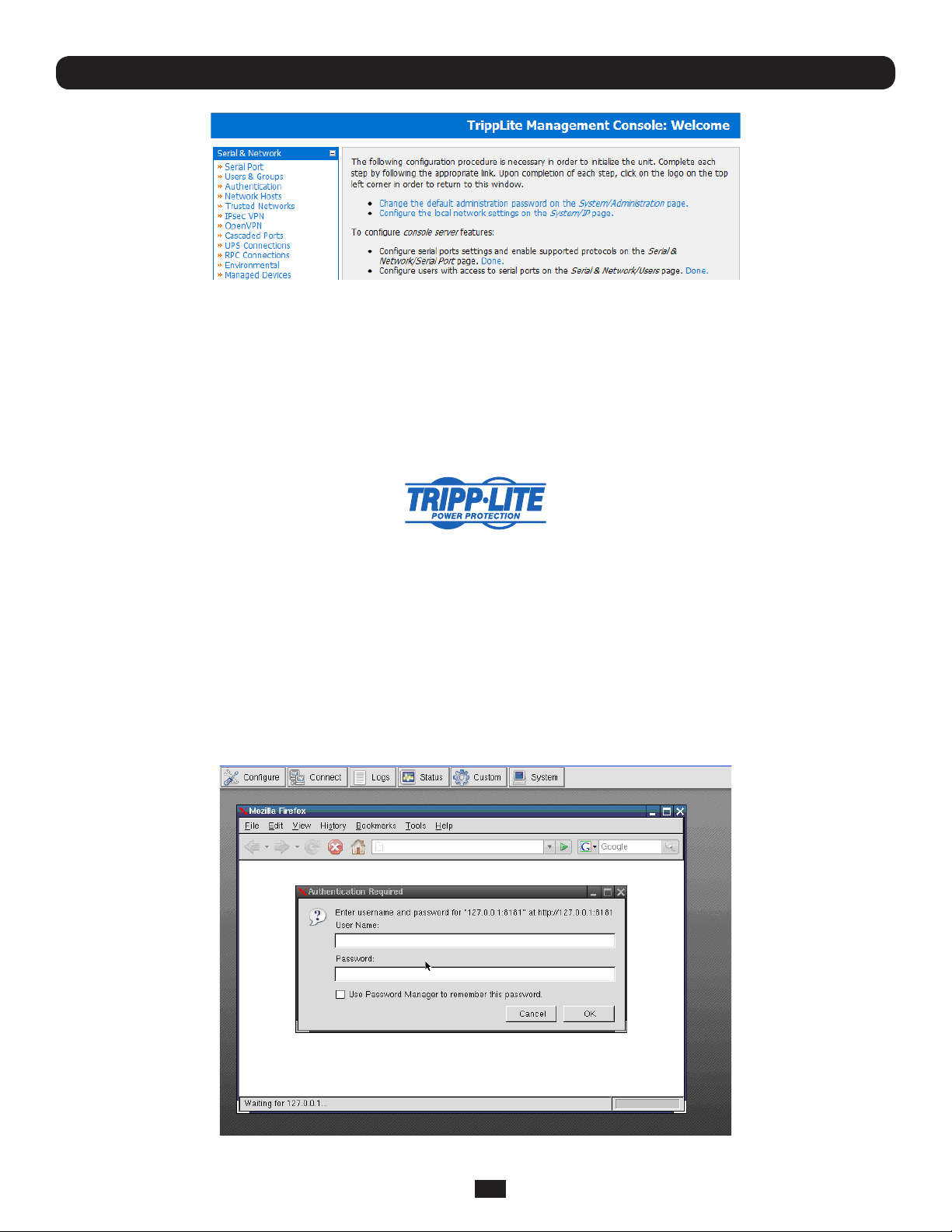
A Welcome screen, which lists initial installation configuration steps, will be displayed. These steps are:
• Change default administration password (System/Administration page. Refer Chapter 3.2)
• Configure the local network settings (System/IP page. Refer Chapter 3.3)
To configure Console Server features:
• Configure serial ports settings (Serial & Network/Serial Port page. Refer Chapter 4)
• Configure user port access (Serial & Network/Users page. Refer Chapter 4)
After completing each of the above steps, you can return to the configuration list by clicking the Tripp Lite logo in the top left corner
of the screen:
Note: If you are not able to connect to the Management Console at 192.168.0.1 or if the default Username / Password were
not accepted then reset your Console Server (refer Chapter 10)
3.1.3 Initial B092-016 connection
You can configure the B092-016 Console Server using a connected computer and browser connection as described in the two
sections above, or you can configure it directly. To do this you will need to connect a console (keyboard, mouse and display) or
a KVM switch directly to its mouse, keyboard and VGA ports. When you initially power on the B092-016, you will be prompted
on your directly connected video console to log in
• Enter the default administration username and password (Username: root Password: default). The B092-016 control
panel will be displayed
• Click the Configure button on the control panel. This will load the Firefox browser and open the B092-016 Management Console
• At the Management Console menu select System: Administration
21
Page 22
Chapter 3: Initial System Configuration
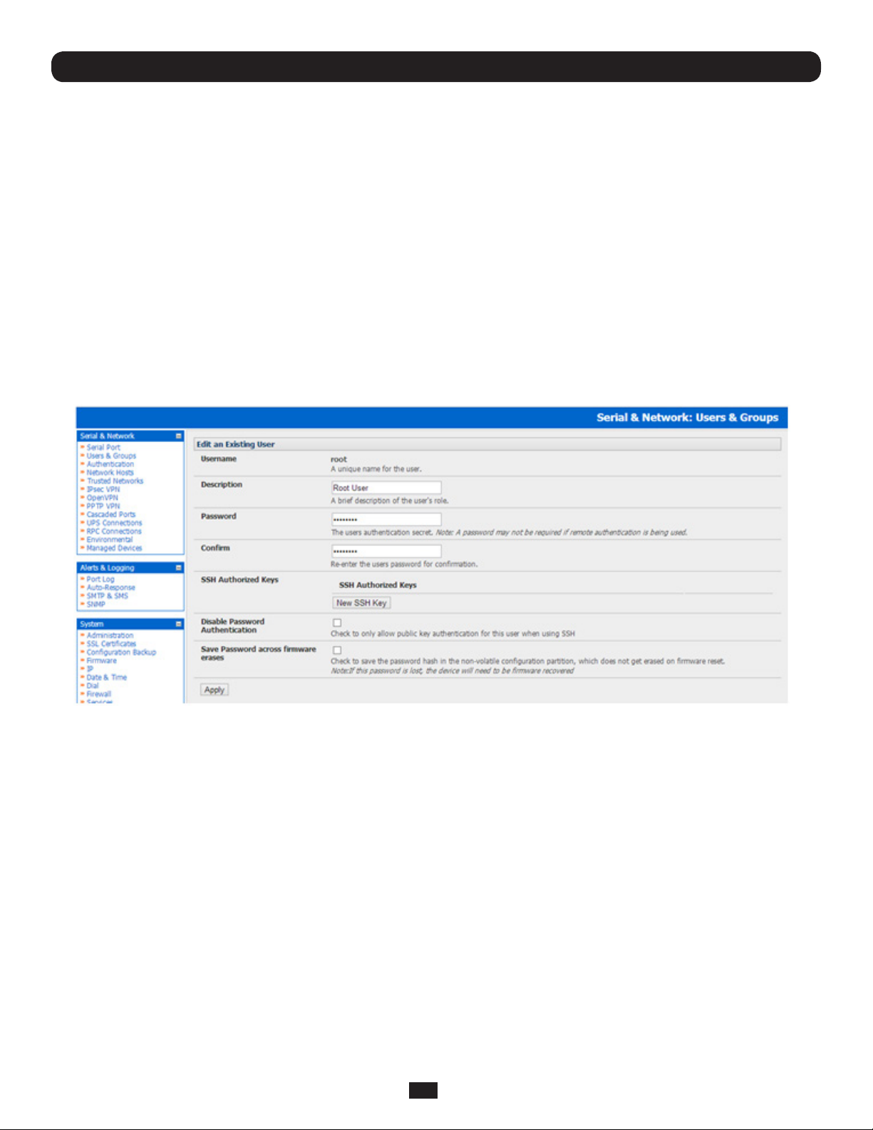
3.2 Administrator Password
For security reasons, only the administration user named root can initially log into your Console Server. Only those people who
know the root password can access and reconfigure the Console Server itself.
However, anyone who correctly guesses the root password (and the default root password which is default) could gain access.
It is therefore essential that you enter and confirm a new root password before giving the Console Server any access to, or
control of, your computers and network appliances.
• Select Change default administration password from the Welcome page, which will take you to Serial & Network:
Users & Groups
• Select Edit for the user root
• Add a new Password and then re-enter it in Confirm. This is the new password for root, the main administrative user
account, so it is important that you choose a complex password, and keep it safe
Note: There are no restrictions on the characters that can be used in the System Password (which can contain up to 254
characters). However, only the first eight Password characters are used to make the password hash.
• Click Apply
Note: If the Console Server has flash memory you will be given the option to Save Password across firmware erases.
Checking this will save the password hash in the non-volatile configuration partition, which does not get erased on firmware
reset. However take care as if this password is lost, the device will need to be firmware recovered.
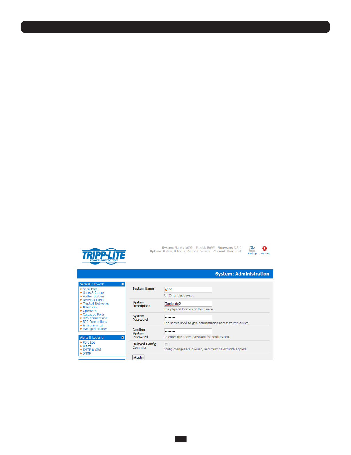
• Select System: Administration
22
Page 23
Chapter 3: Initial System Configuration
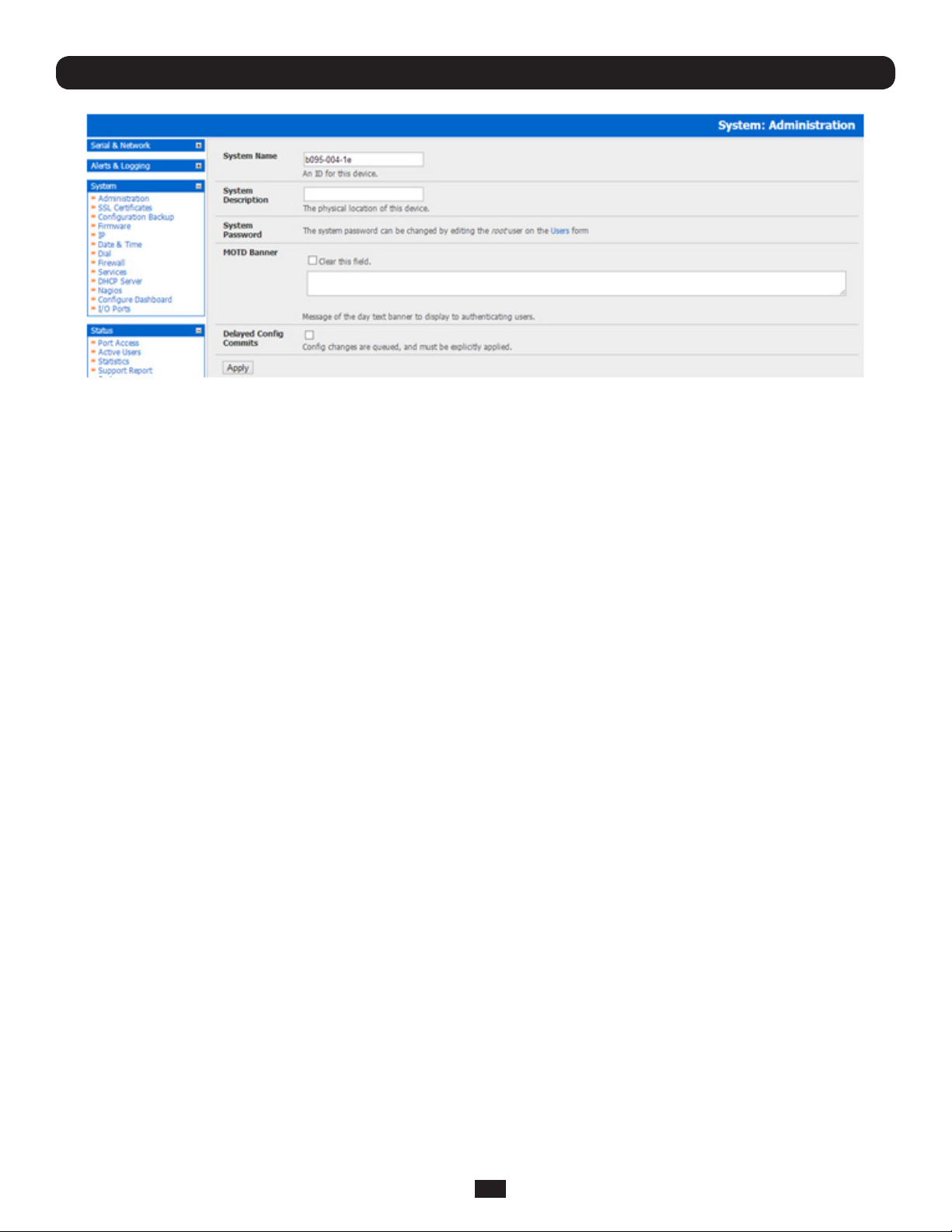
• You may now wish to enter a System Name and System Description for the Console Server to give it a unique ID and
make it simple to identify
Note: The System Name can contain from 1 to 64 alphanumeric characters (however you can also use the special characters
“-” “_” and “.” ). There are no restrictions on the characters that can be used in the System Description (which can contain up
to 254 characters).
• The MOTD Banner can be used to display a “message of the day” text to authenticating users when the ssh, ftp or web
access the Console Server
• Click Apply. As you have changed the password you will be prompted to log in again. This time use the new password
Note: If you are not confident your Console Server has been supplied with the current release of firmware, you can upgrade.
Refer to Upgrade Firmware - Chapter 10
3.2.1 Set up new administrator
It is also recommended that you set up a new Administrator user as soon as convenient and log-in as this new user for all
ongoing administration functions (rather than root).
This Administrator can be configured in the admin group with full access privileges through the Serial & Network: Users &
Groups menu (refer to Chapter 4 for details)
23
Page 24
Chapter 3: Initial System Configuration
3.3 Network IP Address
It is time to enter an IP address for the principal 10/100 LAN port on the Console Server; or enable its DHCP client so that it
automatically obtains an IP address from a DHCP server on the network to which it is to be connected.
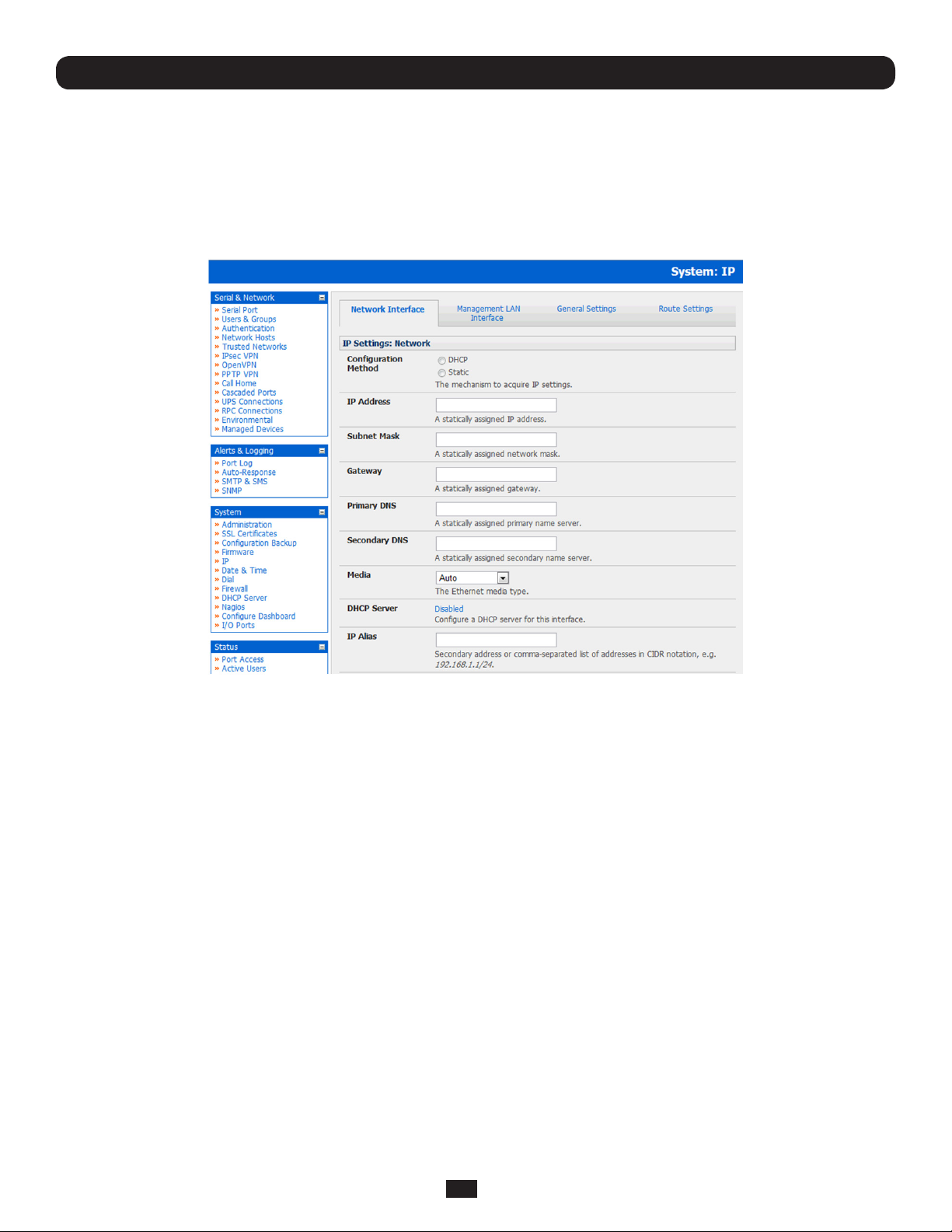
• On the System: IP menu select the Network Interface page then check DHCP or Static for the Configuration Method
• If you select Static you must manually enter the new IP Address, Subnet Mask, Gateway and DNS server details. This
selection automatically disables the DHCP client
• If you selected DHCP the Console Server will look for configuration details from a DHCP server on your management LAN.
This selection automatically disables any static address. The Console Server MAC address can be found on a label on the
base plate
Note: In its factory default state (with no Configuration Method selected) the Console Server has its DHCP client enabled, so
it automatically accepts any network IP address assigned by a DHCP server on your network. In this initial state, the Console
Server will then respond to both its Static address (192.168.0.1) and its newly assigned DHCP address
• By default the Console Server LAN port auto detects the Ethernet connection speed. However you can use the Media
menu to lock the Ethernet to 10 Mb/s or 100Mb/s and to Full Duplex (FD) or Half Duplex (HD)
Note: If you have changed the Console Server IP address, you may need to reconfigure your PC/workstation so it has an IP
address that is in the same network range as this new address (as detailed in an earlier note in this chapter)
• Click Apply
• You will need to reconnect the browser on the PC/workstation that is connected to the Console Server by entering
http://new IP address
24
Page 25
Chapter 3: Initial System Configuration
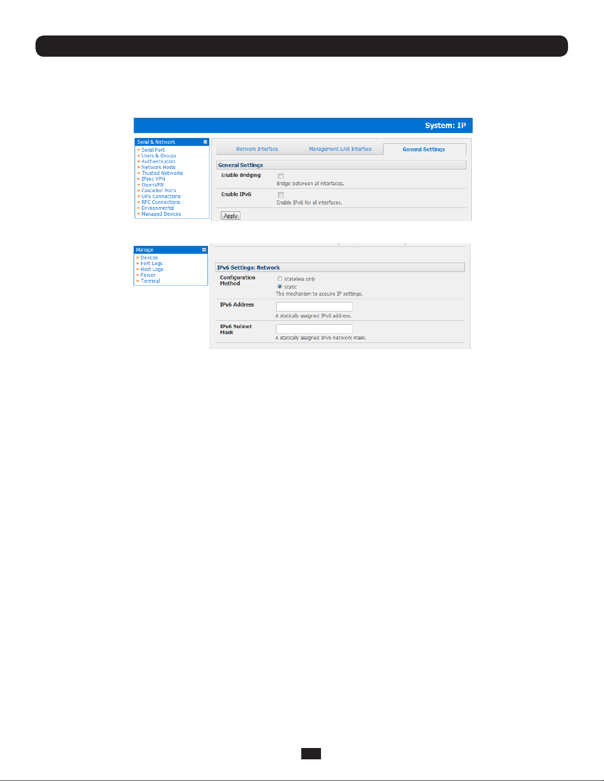
3.3.1 IPv6 configuration
By default, the Console Server Ethernet interfaces support IPv. However, they can also be configured for IPv6 operation:
• On the System: IP menu select General Settings page and check Enable IPv6
• You will then need to configure the IPv6 parameters on each network interface page
25
Page 26
Chapter 3: Initial System Configuration
3.3.2 Dynamic DNS (DDNS) configuration
Dynamic DNS (DDNS) enables a Console Server with a dynamically assigned IP address (that may change from time to time)
to be located using a fixed host or domain name.
• The first step in enabling DDNS is to create an account with the supported DDNS service provider of your choice.
Supported DDNS providers include:
o DyNS www.dyns.cx
o dyndns.org www.dyndns.org
o GNUDip gnudip.cheapnet.net
o ODS www.ods.org
o TZO www.tzo.com
o 3322.org (Chinese provider) www.3322.org
Upon registering with the DDNS service provider, you will select a username and password, as well as a hostname that
you will use as the DNS name (to allow external access to your machine using a URL).
The Dynamic DNS service providers allow the user to choose a hostname URL and set an initial IP address to
correspond to that hostname URL. Many Dynamic DNS providers offer a selection of URL hostnames available for free
use with their service. However, with a paid plan, any URL hostname (including your own registered domain name) can
be used.
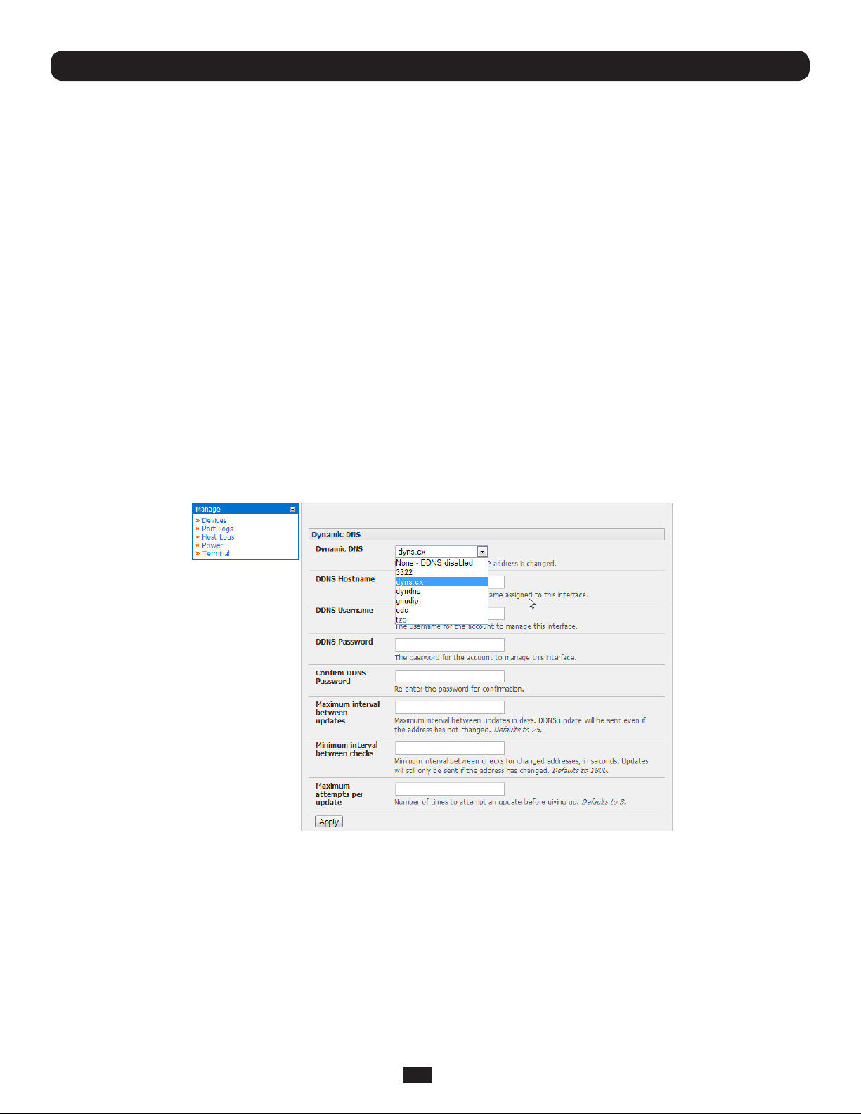
You can now enable and configure DDNS on any of the Ethernet or cellular network connections on the Console Server (by
default DDNS is disabled on all ports):
• Select the DDNS service provider from the drop down Dynamic DNS list on the System:IP or System:Dial menu
• In DDNS Hostname enter the fully qualified DNS hostname for your console server e.g. your-hostname.dyndns.org
• Enter the DDNS Username and DDNS Password for the DDNS service provider account
• Specify the Maximum interval between updates - in days. A DDNS update will be sent even if the address has not changed
• Specify the Minimum interval between checks for changed addresses - in seconds. Updates will still only be sent if the
address has changed
• Specify the Maximum attempts per update i.e. the number of times to attempt an update before giving up (defaults to 3)
26
Page 27

Chapter 3: Initial System Configuration
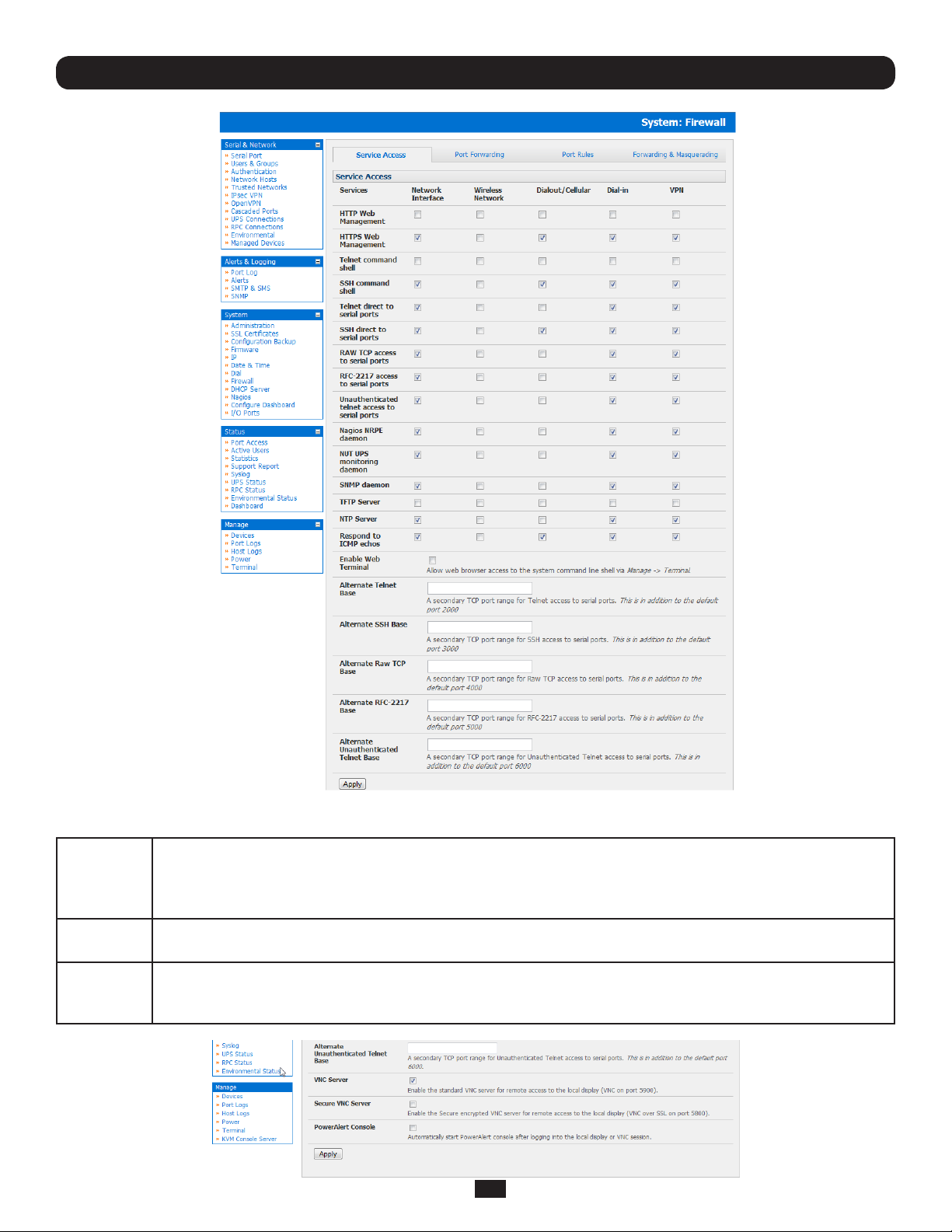
3.4 System Services and Service Access
Service Access specifies which access protocols/services can be used to access the Console Server (and connected serial ports).
The Administrator can access and configure the Console Server (and connected devices) using a range of access protocols/
services – and for each such access, the particular service must be running with access through the firewall enabled.
By default HTTP, HTTPS, Telnet and SSH services are running, and these services are enabled on all network interfaces. However,
again by default, only HTTPS and SSH access to the Console Server is enabled, while HTTP and Telnet access is disabled.
For other services, such as SNMP/Nagios NRPE/NUT, the service must first be started on the relevant network interface using
Service Settings. Then the Service Access can be set to allow or block access.
To enable and configure a service:
• Select the Service Settings tab on the System: Services page and enable required services
To change the access settings:
• Select the Service Access tab on the System: Services page. This will display the service currently enabled for the
Console Server’s network interfaces.
o Network interface (for the principal Ethernet connection)
o Dial out (V90 and cellular modem)
o Dial in (internal or external V90 modem)
o WiFi (802.11 wireless)
o OoB Failover (second Ethernet connections)
o VPN (IPSec or Open VPN connection over any network interface)
• Check/uncheck for each network which service access is to be enabled /disabled
In the example shown below local Administrators on local Network Interface LAN do not have Telnet access to the Console
Server itself (only SSH and HTTPS access) but they do have Telnet access to the serial console devices attached to the
Console Server.
27
Page 28

Chapter 3: Initial System Configuration
The Services Access settings specify which services the Administrator can use over which network interface to access the
console server. It also nominates the enabled services that the Administrator and the User can use to connect through the
Console Server to attached serial and network connected devices.
• The following general service access options can be specified:
HTTPS
HTTP
Telnet
SSH
• There are also a number of related service options that can be configured at this stage:
SNMP
TFTP/
FTP
Ping
Nagios
NUT
This ensures the Administrator has secure browser access to all the Management Console menus on the Console
Server. It also allows appropriately configured Users secure browser access to selected Manage menus. For
information on certificate and user client software configuration refer Chapter 9 - Authentication. By default
HTTPS is enabled, and it is recommended that only HTTPS access be used if the Console Server is to be
managed over any public network (e.g. the Internet).
The HTTP service allows the Administrator basic browser access to the Management Console. It is recommended
the HTTP service be disabled if the Console Server is to be remotely accessed over the Internet.
This gives the Administrator telnet access to the system command line shell (Linux commands). While this may
be suitable for a local direct connection over a management LAN, it is recommended this service be disabled if
the Console Server is to be remotely administered. This service may also be useful for local Administrator and the
User access to selected serial consoles
This service provides secure SSH access. It is recommended you choose SSH as the protocol where the
Administrator connects to the Console Server over the Internet or any other public network. This will provide
authenticated communications between the SSH client program on the remote PC/workstation and the SSH sever
in the Console Server. For more information on SSH configuration refer Chapter 9 - Authentication.
This will enable netsnmp in the Console Server, which will keep a remote log of all posted information. SNMP is
disabled by default. To modify the default SNMP settings, the Administrator must make the edits at the command
line as described in Chapter 15 – Advanced Configuration
If a USB flash card or internal flash is detected on the Console Server, then enabling this service will set up
default tftp and ftp servers on the USB flash. These server are used to store config files, maintain access and
transaction logs etc. Files transferred using tftp will be stored under /var/tmp/usbdisk/tftpboot
This allows the Console Server to respond to incoming ICMP echo requests. Ping is enabled by default, however
for security reasons this service should generally be disabled post initial configuration
Access to the NUT UPS monitoring and Nagios NRPE monitoring daemons
Access to the NUT UPS monitoring and Nagios NRPE monitoring daemons
• And there are some serial port access parameters that can be configured on this menu:
Base
RAW/
Direct
• Click Apply. As you apply your services selections, the screen will be updated with a confirmation message:
Message Changes to configuration succeeded
The Console Server uses specific default ranges for the TCP/IP ports for the various access services that Users
and Administrators can use to access devices attached to serial ports (as covered in Chapter 4 – Configuring
Serial Ports). The Administrator can also set alternate ranges for these services, and these secondary ports will
then be used in addition to the defaults.
The default TCP/IP base port address for telnet access is 2000, and the range for telnet is IP Address: Port (2000
+ serial port #) i.e. 2001 – 2048. So if the Administrator were to set 8000 as a secondary base for telnet then
serial port #2 on the Console Server can be telnet accessed at IP Address:2002 and at IP Address:8002. The
default base for SSH is 3000; for Raw TCP is 4000; and for RFC2217 it is 5000
You can also specify that serial port devices can be accessed from nominated network interfaces using Raw TCP,
direct Telnet/SSH, unauthenticated Telnet services etc
28
Page 29
Chapter 3: Initial System Configuration
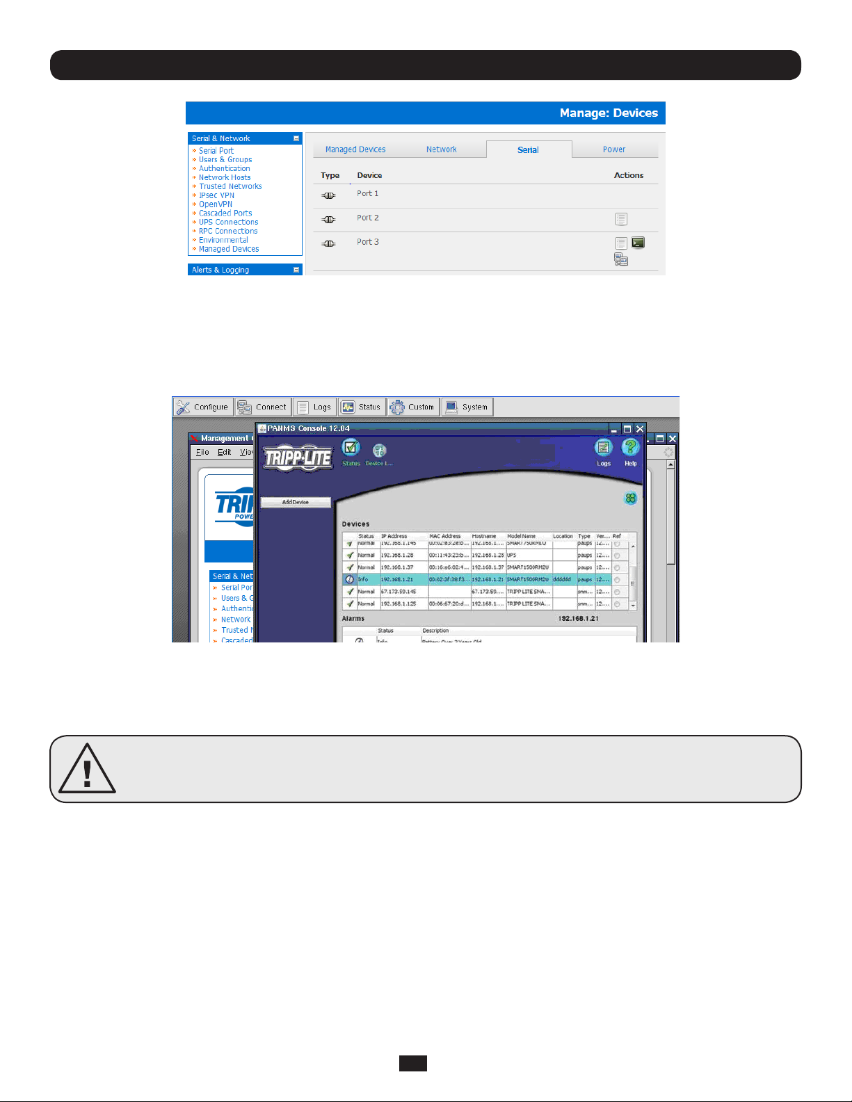
• The B092-016 Console Server with PowerAlert also presents some additional service and configuration options:
VNC
Secure
VNC
PowerAlert
The B092-016 Console Server has an internal VNC server. When enabled, it allows remote users to connect
to the Console Server and run the PowerAlert software and any other embedded thin client programs as if they
were plugged in locally to the KVM connectors on the B092-016 (refer to Chapter 16 for more details). Users
connect using port 5900 and need to run a VNC client applet
This enables a secure encrypted remote connection using VNC over SSL on port 5800 to the B092-016
Console Server (refer to Chapter 16)
This configuration option will automatically start the PowerAlert application on the B092-016 and display
the console as soon as you log into the local display or VNC session (refer to Chapter 16). The complete
PowerAlert manual can be downloaded at www.tripplite.com/EN/support/PowerAlert/Downloads.cfm
29
Page 30

Chapter 3: Initial System Configuration
3.4.1 Brute force protection
Brute force protection (Micro Fail2ban) temporarily blocks source IPs that show malicious signs, such as too many password
failures. This may help mitigate scenarios where the appliance’s network services are exposed to an untrusted network such
as the public WAN, and scripted attacks or software worms are attempting to guess (brute force) user credentials and gain
unauthorized access.
Brute Force Protection may be enabled for the listed services. Once protection is enabled, 3 or more failed connection
attempts within 60 seconds from a specific source IP trigger it to be banned from connecting for the next 60 seconds. Active
Bans are also listed and may be refreshed by reloading the page.
Note: When an appliance is running on an untrusted network, it is recommended that a variety of strategies are used to lock
down remote access. This includes strong passwords (or even better, SSH public key authentication), VPN, and using Firewall
Rules to whitelist remote access from trusted source networks only.
30
Page 31

Chapter 3: Initial System Configuration
3.5 Communications Software
You need to configure the access protocols that the communications software on the Administrator and User Computer will
use when connecting to the Console Server (and when connecting to serial devices and network hosts which are attached to
the Console Server).
This section provides an overview of the communications software tools that can be used on the remote computer. Tripp Lite
recommends the SDT Connector software tool that is provided with the Console Server; however, generic tools such as PuTTY
and SSHTerm may also be used.
3.5.1 SDT Connector
We recommend using the SDT Connector communications software for all communications with Console Servers. Each
Console Server is supplied with an unlimited number of SDT Connector licenses to use with that Console Server.
SDT Connector is a lightweight tool that enables Users and Administrators to securely access the Console Server, and the
various computers, network devices and appliances that may be serially or network- connected to the Console Server. SDT
Connector can be installed on Windows 2000, XP, 2003, Vista and on most Linux, UNIX and Solaris computers as detailed in
Chapter 6.
3.5.2 PuTTY
Communications packages like PuTTY can be also used to connect to the Console Server command line (and to connect to
serially attached devices as covered in Chapter 4). PuTTY is a freeware implementation of Telnet and SSH for Win32 and UNIX
platforms. It runs as an executable application without needing to be installed onto your system. PuTTY (the Telnet and SSH
client itself) can be downloaded at http://www.tucows.com/preview/195286.html
• To use PuTTY for an SSH terminal session from a Windows client,
enter the Console Server’s IP address as the ‘Host Name (or IP
address)’
• To access the Console Server command line, select ‘SSH’ as the
protocol and use the default IP Port 22
• Click ‘Open’ and the Console Server login prompt will appear. (You
may also receive a ‘Security Alert’ that the host’s key is not
cached. Choose ‘yes’ to continue.)
• Using the Telnet protocol is similarly simple, but you need to use
the default port 23
31
Page 32

Chapter 3: Initial System Configuration
3.5.3 SSHTerm
Another common communications package that may be useful is SSHTerm. This is an open source package that can be
downloaded from http://sourceforge.net/projects/sshtools
• To use SSHTerm for an SSH terminal session from a Windows Client, simply Select
the ‘File’ option and click on ‘New Connection’.
• A new dialog box will appear for your ‘Connection Profile’. Type in the host name or
IP address (for the Console Server unit) and the TCP port that the SSH session will
use (port 22). Then type in your username and choose password authentication and
click Connect.
• A message may appear about the host key fingerprint. You will need to select ‘Yes’
or ‘Always’ to continue.
• The next step is password authentication. You will be prompted for your username
and password from the remote system. You will then be logged on to the Console
Server
32
Page 33

Chapter 3: Initial System Configuration
3.6 Management Network Configuration
The B096-048/032/016 Console Server Management Switches and B094-008-2E-M-F / B094-008-2E-V Console Server
each have an additional network port that can be configured as a Management LAN port or as a failover/ OOB access port.
3.6.1 Enable the Management LAN
The B096-048/032/016 Console Server Management Switches and B094-008-2E-M-F / B094-008-2E-V Console Server
have dual Ethernet ports which can be configured to provide a management LAN gateway. With this configuration, the
B096-048/032/016 and B094-008-2E-M-F / B094-008-2E-V provide firewall, router and DHCP server features and you can
connect managed hosts to this management LAN.
These features are all disabled by default. To configure the Management LAN gateway:
• Select the Management LAN Interface page on the System: IP menu and uncheck Disable
• Configure the IP Address and Subnet Mask for the Management LAN (but leave the DNS fields blank)
• Click Apply
Note: With the B094-008-2E-M-F, B096-048, B094-008-2E-V, B096-032 and B096-016 the second Ethernet port can
be configured as either a gateway port or it can be configured as an OOB/Failover port - but not both. So ensure you did not
allocate the Management LAN as the Failover Interface when you configured the principal Network connection on the
System: IP menu
33
Page 34

Chapter 3: Initial System Configuration
The management gateway function is now enabled with default firewall and router rules. By default these rules are configured
so the Management LAN can only be accessible by SSH port forwarding. This ensures the remote and local connections to
Managed Devices on the Management LAN are secure.
3.6.2 Configure the DHCP server
The Console Servers also host a DHCP server which by default is disabled. The DHCP server enables the automatic
distribution of IP addresses to devices on the Network Interface or the Management LAN. To enable the DHCP server:
• On the System: IP menu select the Management LAN Interface page and click the Disabled label in the DHCP Server
field (or go to the System: DHCP Server menu and check Enable DHCP Server)
• Enter the Gateway address that is to be issued to the DHCP clients. If this field is left blank, the Console Server’s IP
address will be used
• Enter the Primary DNS and Secondary DNS address to issue the DHCP clients. Again if this field is left blank, Console
Server’s IP address is used, so leave this field blank for automatic DNS server assignment
• Optionally enter a Domain Name suffix to issue DHCP clients
• Enter the Default Lease time and Maximum Lease time in seconds. The lease time is the time that a dynamically
assigned IP address is valid before the client must request it again
• Click Apply
The DHCP server will sequentially issue IP addresses from a specified address pool(s):
• Click Add in the Dynamic Address Allocation Pools field
• Enter the DHCP Pool Start Address and End Address and click Apply
34
Page 35

Chapter 3: Initial System Configuration
The DHCP server also supports pre-assigning IP addresses to be allocated only to specific MAC addresses and reserving IP
addresses to be used by connected hosts with fixed IP addresses. To reserve an IP addresses for a particular host:
• Click Add in the Reserved Addresses field
• Enter the Hostname, the Hardware Address (MAC) and the Statically Reserved IP address for the DHCP client and
click Apply
When DHCP has initially allocated hosts addresses it is recommended to copy these into the pre-assigned list so the same IP
address will be reallocated in the event of a reboot.
3.6.3 Select Failover or broadband OOB
The Console Servers provide a failover option so in the event of a problem using the main LAN connection for accessing the
Console Server; an alternate access path is automatically used.
• By default the failover is not enabled. To enable, select the Network Interface page on the System: IP menu
• Now select the Failover Interface to be used in the event of an outage on the main network. This can be:
o a second Ethernet connection on the B094-008-2E-M-F / B094-008-2E-V or B096-048/032/016
o the B094-008-2E-M-F / B094-008-2E-V or B096-048/032/016 internal modem
o an external modem device connected to the Console Server
• Click Apply. You have selected the failover method. However it is not active until you have specified the external sites to
be probed to trigger failover, and set up the failover ports themselves. This is covered in Chapter 5.
Note: The second Ethernet port on the B094-008-2E-M-F / B094-008-2E-V or B096-048/032/016 can be configured as
either a Management LAN gateway port or it can be configured as an OoB/Failover port - but not both. So ensure you did not
configure this port as the Management LAN on the System: IP menu
3.6.4 Bridging the network ports
By default the B096-048/032/016 Console Server's Management LAN network port can only be accessed using SSH
tunneling /port forwarding or by establishing an IPsec VPN tunnel to the Console Server.
However the network ports on the Console Servers can be bridged.
• Select Enable Bridging on the System: IP General Settings menu
35
Page 36

Chapter 3: Initial System Configuration
With bridging enabled:
• the Ethernet ports are transparently interconnected at the data link layer (layer 2)
• the Ethernet ports are configured collectively using the Network Interface menu
• network traffic is forwarded between all Ethernet ports with no firewall restrictions
• the Management LAN Interface and Out-of-Band/Failover Interface functions are removed and the DHCP Server is
disabled
An alternate to bridging is to use the firewall/routing functions (packet filtering, port forwarding, masquerading) functions
detailed in chapter 5. This can provide firewalled remote IP access to devices on the Management LAN.
3.6.5 Wireless LAN
Console Servers can be fitted externally with an external 802.11 wireless USB dongle. The wireless device will then be autodetected on power up and you will be presented with a Wireless LAN Interface menu in the System: IP menu
• The wireless LAN is deactivated by default so to activate it first uncheck Disable
To configure the IP settings of the wireless LAN:
• Select DHCP or Static for the Configuration Method
o If you selected Static then manually enter the new IP Address, Subnet Mask, Gateway and DNS server details.
This selection automatically disables the DHCP client
o If you selected DHCP the Console Server will look for configuration details from a DHCP server on your
management LAN. This selection automatically disables any static address. The Console Server MAC address can
be found on a label on the base plate
• The wireless LAN when enabled will operate as the main network connection to the console server so failover is available
(though it not enabled by default). Use Failover Interface to select the device to failover to in case of wireless outage
and specify Probe Addresses of the peers to probed for connectivity detection
• Configure the Wireless Client to select the local wireless network which will serve as the main network connection to the
Console Server.
o Enter the appropriate SSID (Set Service Identifier) of the wireless access point to connect to
o Select the Wireless Network Type where Infrastructure is used to connect to an access point and Ad-hoc to
connect directly to a computer
o Select the Wireless Security mode of the wireless network (WEP, WPA etc) and enter the required
Key/ Authentication/ Encryption settings
Note: The Wireless screen in Status: Statistics will display all the locally accessible wireless LANs (with SSID and Encryption/
Authentication settings). You can also use this screen to confirm you have successfully connected to the selected access point.
The Console Server enables access and control of serially-attached devices and network-attached devices (hosts). The
Administrator must configure access privileges for each of these devices, and specify the services that can be used to control
the devices. The Administrator can also set up new users and specify each user’s individual access and control privileges.
This chapter covers each of the steps in configuring hosts and serially attached devices:
• Configure Serial Ports – setting up the protocols to be used in accessing serially-connected devices
• Users & Groups – setting up users and defining the access permissions for each of these users
36
Page 37

Chapter 3: Initial System Configuration
• Authentication – this is covered in more detail in Chapter 9
• Network Hosts – configuring access to local network connected computers or appliances (hosts)
• Configuring Trusted Networks - nominate specific IP addresses that trusted users access from
• Cascading and Redirection of Serial Console Ports
• Connecting to Power (UPS PDU and IPMI) and Environmental Monitoring (EMD) devices
• Serial Port Redirection – using the VirtualPort windows and Linux clients
• Managed Devices - presents a consolidated view of all the connections
• IPSec – enabling IPSec VPN connection
• OpenVPN - enabling IPSec OpenVPN connection
• PPTP – setting up point to point connection
3.6.6 Static routes
Firmware 3.4 and later support static routes which provide a very quick way to route data from one subnet to another. You
can hard code a path that specifies to the console server/router which path to take to get to a particular subnet. This may be
useful for remotely accessing various subnets at a remote site when using the cellular OoB connection.
To add to the static route to the route table of the system:
• Select the Route Settings tab on the System: IP General Settings menu
• Enter a meaningful Route Name for the route
• In the Destination Network/Host field, enter the IP address of the destination network/host that the route provides access to
• Enter a value in the Destination netmask field that identifies the destination network or host. Use any number between
0 and 32. A subnet mask of 32 identifies a host route.
• In the Route Gateway field, enter the IP address of a router that will route packets to the destination network (can be left
blank)
• Select the Interface to use to reach the destination (may be left as None)
• Enter a value in the Metric field that represents the metric of this connection. This generally only has to be set if two or
more routes conflict or have overlapping targets. Any number equal to or greater than 0
• Click Apply
Note: The route details page provides a list of network interfaces and modems to which a route can be bound. In the case of
a modem, the route will be attached to any dialup session which is established via that device. A route can be specified with
a gateway, an interface or both. If the specified interface is not active for whatever reason, then routes configured for that
interface will not be active.
37
Page 38

Chapter 4: Serial Port, Device and User Configuration
4.1 Configuring Serial Ports
To configure a serial port you must first set the Common Settings (Chapter 4.1.1) that are to be used for the data connection
to that port (e.g. baud rate) and the mode the port is to operate in. Each port can be set to support one of six operating
modes:
i. Disabled Mode is the default, the serial port is inactive
ii. Console Server Mode (Chapter 4.1.2) enables general access to the serial console port on serially attached devices
iii. Device Mode (Chapter 4.1.3) sets the serial port up to communicate with an intelligent serial controlled PDU, UPS or
Environmental Monitor Devices (EMD)
iv. SDT Mode (Chapter 4.1.4) enables graphical console access (with RDP, VNC, HTTPS etc) to hosts that are serially
connected
v. Terminal Server Mode (Chapter 4.1.5) sets the serial port to await an incoming terminal login session
vi. Serial Bridge Mode (Chapter 4.1.6) enables the transparent interconnection of two serial port devices over a network
To select the serial port to configure:
• Select Serial & Network: Serial Port and click Edit on the port to be reconfigured
Note: If you wish to set the same protocol options for multiple serial ports at once, click Edit Multiple Ports and select which
ports you wish to configure as a group
• When you have configured the common settings and the mode for each port, set up any remote syslog (Chapter 4.1.7),
then click Apply
• If the Console Server has been configured with distributed Nagios monitoring enabled then you will also be presented
with Nagios Settings options to enable nominated services on the Host to be monitored (refer to Chapter 10 – Nagios
Integration)
38
Page 39

Chapter 4: Serial Port, Device and User Configuration
4.1.1 Common Settings
There are a number of common settings available for each serial port. These are independent of the mode in which the port
is being used. These serial port parameters must be set so they match the serial port parameters on the device which is
attached to that port.
• Select Serial & Network: Serial Port and click Edit
• Specify a label for the port
• Select the appropriate Baud Rate, Parity, Data Bits, Stop Bits and Flow Control for each port (and ensure they match the
settings for serial device that is connected). The Signaling Protocol is hard configured to be RS232
Note: The serial ports are all set at the factory to RS232 9600 baud, no parity, 8 data bits, 1 stop bit and Console Server
Mode. The baud rate can be changed to 2400 – 230400 baud using the management console. Lower baud rates (50, 75,
110, 134, 150, 200, 300, 600, 1200, 1800 baud) can be configured from the command line as detailed in Chapter 14
39
Page 40

Chapter 4: Serial Port, Device and User Configuration
4.1.2 Console Server Mode
Select Console Server Mode to enable remote management access to the serial console that is attached to the serial port:
Logging Level This specifies the level of information to be logged and monitored (refer to Chapter 7 - Alerts and Logging)
Telnet Check to enable Telnet access to the serial port. When enabled, a Telnet client on a User or Administrator’s
computer can connect to a serial device attached to this serial port on the Console Server. The default port
address is IP Address _ Port (2000 + serial port #) i.e. 2001 – 2048
Telnet communications are unencrypted, so this protocol is generally recommended for local connections
only. However, if the remote communications are being tunneled with SDT Connector, then Telnet can be
used to securely access these attached devices (see Note below).
With Win2000/XP/NT you can run Telnet from the command prompt (cmd.exe). Vista comes with a Telnet
client and server but they are not enabled by default. To enable Telnet, simply:
• Log in as Admin and go to Start/ Control Panel/Programs and Features
• Select Turn Windows Features On or Off, check the Telnet Client and click OK
40
Page 41

Chapter 4: Serial Port, Device and User Configuration
Note: In Console Server mode, Users and Administrators can use SDT Connector to set up secure Telnet connections that are
SSH tunneled from their client computers to the serial port on the Console Server with a simple point-and-click.
To use SDT Connector to access consoles on the Console Server serial ports, configure the SDT Connector with the Console
Server as a gateway, then as a host. Now enable Telnet service on Port (2000 + serial port #) i.e. 2001–2048. Refer to Chapter
6 for more details on using SDT Connector for Telnet and SSH access to devices attached to the Console Server serial ports.
You can also use standard communications packages like PuTTY to set a direct Telnet (or SSH) connection to the serial ports
(refer Note below):
Note: PuTTY also supports Telnet (and SSH). The procedure to set up a Telnet session is simple: Enter the Console Server’s
IP address as the ‘Host Name (or IP address)’. Select ‘Telnet’ as the protocol and set the ‘TCP port’ to 2000 plus the physical
serial port number (i.e. 2001 to 2048).
Click the ‘Open’ button. You may then receive a ‘Security Alert’ that the host’s key is not cached. Choose ‘yes’ to continue. You
will then be presented with the login prompt of the remote system connected to the serial port chosen on the Console Server.
You can login as normal and use the host serial console screen.
PuTTY can be downloaded at http://www.tucows.com/preview/195286.html
41
Page 42

Chapter 4: Serial Port, Device and User Configuration
SSH It is recommended that the User or Administrator uses SSH as the protocol for connecting to serial
consoles attached to the Console Server when communicating over the Internet or any other public
network. This will provide an authenticated, encrypted connection between the SSH client program
on the remote user’s computer and the Console Server. The user’s communication with the serial
device attached to the Console Server is therefore secure.
It is recommended for Users and Administrators to use SDT Connector when making an SSH
connection to the consoles on devices attached to the Console Server’s serial ports. Configure the
SDT Connector with the Console Server as a gateway, then as a host, and enable SSH service on
Port (3000 + serial port #) i.e. 3001-3048 (refer to Chapter 6).
You can also use common communications packages, like PuTTY or SSHTerm to SSH connect
directly to port address IP Address _ Port (3000 + serial port #) i.e. 3001–3048.
Alternately SSH connections can be configured using the standard SSH port 22. The serial port
being accessed is then identified by appending a descriptor to the username. This syntax supports
any of:
<username>:<portXX>
<username>:<port label>
<username>:<ttySX>
<username>:<serial>
So for a user named 'fred' to access serial port 2, when setting up the SSHTerm or the PuTTY SSH
client, instead of typing username = fred and ssh port = 3002, the alternate is to type username
= fred:port02 (or username = fred:ttyS1) and ssh port = 22.
Or, by typing username=fred:serial and ssh port = 22, the user is presented with a port selection
option:
This syntax enables users to set up SSH tunnels to all serial ports with only a single IP port 22
having to be opened in their firewall/gateway.
TCP RAW TCP allows connections directly to a TCP socket. Communications programs such as PuTTY
also support RAW TCP; however, this protocol would usually be used by a custom application. For
RAW TCP, the default port address is IP Address _ Port (4000 + serial port #) i.e. 4001 – 4048.
RAW TCP also enables the serial port to be tunneled to a remote Console Server, so two serial port
devices can be transparently interconnected over a network (see Chapter 4.1.6 – Serial Bridging).
RFC2217 Selecting RFC2217 enables serial port redirection on that port. For RFC2217, the default port
address is IP Address _ Port (5000 + serial port #) i.e. 5001 – 5048.
You will also need to run serial port redirector software on your desktop computer. This software,
which supports RFC2217 virtual com ports, is available commercially and as freeware, for Windows
UNIX and Linux, and it allows you to use a serial device connected to the remote Console Server as
if it were connected to your local serial port.
42
Page 43

Chapter 4: Serial Port, Device and User Configuration
Unauthenticated Telnet Selecting Unauthenticated Telnet enables Telnet access to the serial port without requiring the user
to provide credentials. When a user accesses the Console Server to Telnet to a serial port they are
normally given a login prompt. However, with unauthenticated Telnet, they connect directly through
to port with any Console Server login at all. This mode is mainly used when you have an external
system (such as conserver) managing user authentication and access privileges at the serial device
level.
For Unauthenticated Telnet, the default port address is IP Address _ Port (6000 + serial port #)
i.e. 6001 – 6048.
IP Alias Enable access to the serial port using a specific IP address, specified in CIDR format. Each serial
port can have one or more IP aliases configured on a per-interface basis. These IP addresses can
only be used to access the specific serial port, accessible using the standard protocol TCP port
numbers of the console server services. For example, SSH on serial port 3 would be accessible on
port 22 of a serial port IP alias (whereas on the console server’s primary address it is available on
port 2003).
This feature can also be configured via the multiple port edit page. In this case the IP addresses
are applied sequentially, with the first selected port getting the IP entered and subsequent ones
getting incremented, with numbers being skipped for any unselected ports. For example if ports
2, 3 and 5 are selected and the IP alias 10.0.0.1/24 is entered for the Network Interface, the
following addresses will be assigned:
Port 2: 10.0.0.1/24
Port 3: 10.0.0.2/24
Port 5: 10.0.0.4/24
Web Terminal Selecting Web Terminal enables web browser access to the serial port via Manage: Devices:
Serial using the Management Console's built in AJAX terminal. Web Terminal connects as the
currently authenticated Management Console user and does not re-authenticate. See section
13.3 for more details.
Accumulation Period By default once a connection has been established for a particular serial port (such as a RFC2217
redirection or Telnet connection to a remote computer) then any incoming characters on that
port are forwarded over the network on a character by character basis. The accumulation period
changes this by specifying a period of time that incoming characters will be collected before then
being sent as a packet over the network
Escape Character This enables you to change the character used for sending escape characters. The default is ~.
Power Menu This setting enables the shell power command so a user can control the power connection to
a Managed Device from command line when they are telnet or SSH connected to the device.
To operate the Managed Device must be set up with both its Serial port connection and Power
connection configured. The command to bring up the power menu is ~p
43
Page 44

Chapter 4: Serial Port, Device and User Configuration
Single Connection This setting limits the port to a single connection so if multiple users have access privileges for
a particular port only one user at a time can be accessing that port (i.e. port “snooping” is not
permitted)
4.1.3 SDT Mode
This setting allows port forwarding of LAN protocols such as RDP, VNC, HTPP, HTTPS, SSH and Telnet through to computers
which are connected locally to the Console Server by their serial COM port. However such port forwarding requires a PPP link
to be set up over this serial port.
Refer to Chapter 6.6 - Using SDT Connector to Telnet or SSH connect to devices that are serially attached to the
Console Server for configuration details
4.1.4 Device (RPC, UPS, EMD) Mode
This mode configures the selected serial port to communicate with a serial controlled Uninterruptible Power Supply (UPS),
serial Remote Power Controller/ Power Distribution Unit (RPC) or Environmental Monitoring Device (EMD)
• Select the desired Device Type (UPS, RPC or EMD)
• Proceed to the appropriate device configuration page (Serial & Network: UPS Connections, RPC Connection or
Environmental) as detailed in Chapter 8 - Power & Environmental Management. The B092-016 Console Server also
allows you to configure ports as UPS devices that PowerAlert will manage. PowerAlert will discover the attached UPS
device and auto-configure. See www.tripplite.com/EN/support/PowerAlert/Downloads.cfm for a complete PowerAlert
manual.
4.1.5 Terminal Server Mode
• Select Terminal Server Mode and the Terminal Type (vt220, vt102, vt100, Linux or ANSI) to enable a getty on the
selected serial port
The getty will then configure the port and wait for a connection to be made. An active connection on a serial device is usually
indicated by the Data Carrier Detect (DCD) pin on the serial device being raised. When a connection is detected, the getty
program issues a login: prompt, and then invokes the login program to handle the actual system login.
Note: Selecting Terminal Server mode will disable Port Manager for that serial port, so data is no longer logged for alerts etc.
44
Page 45

Chapter 4: Serial Port, Device and User Configuration
4.1.6 Serial Bridging Mode
With serial bridging, the serial data on a nominated serial port on one Console Server is encapsulated into network packets
and then transported over a network to a second Console Server where is then represented as serial data. So the two Console
Servers effectively act as a virtual serial cable over an IP network.
One Console Server is configured to be the Server. The Server serial port to be bridged is set in Console Server mode with
either RFC2217 or RAW enabled (as described in Chapter 4.1.2 – Console Server Mode).
For the Client Console Server, the serial port to be bridged must be set in Bridging Mode:
• Select Serial Bridging Mode and specify the IP address of the Server Console Server and the TCP port address of the
remote serial port (for RFC2217 bridging this will be 5001-5048)
• By default the bridging client will use RAW TCP so you must select RFC2217 if this is the Console Server mode you have
specified on the server Console Server
• You may secure the communications over the local Ethernet by enabling SSH however you will need to generate and
upload keys (refer Chapter 14 – Advanced Configuration)
4.1.7 Syslog
In addition to inbuilt logging and monitoring (which can be applied to serial-attached and network-attached management
accesses, as covered in Chapter 7 - Alerts and Logging) the Console Server can also be configured to support the remote
syslog protocol on a per serial port basis:
• Select the Syslog Facility/Priority fields to enable logging of traffic on the selected serial port to a syslog server; and to
appropriately sort and action those logged messages (i.e. redirect them/ send alert email etc.)
For example if the computer attached to serial port 3 should never send anything out on its serial console port, the
Administrator can set the Facility for that port to local0 (local0 .. local7 are meant for site local values), and the Priority to
critical. At this priority, if the Console Server syslog server does receive a message, it will automatically raise an alert. Refer to
Chapter 7 - Alerts & Logging.
45
Page 46

Chapter 4: Serial Port, Device and User Configuration
4.2 Add/ Edit Users
The Administrator uses this menu selection to set up, edit and delete users and to define the access permissions for each of
these users.
Users can be authorized to access specified Console Server serial ports and specified network-attached hosts. These users can
also be given full Administrator status (with full configuration and management and access privileges). To simplify user set up,
they can be configured as members of Groups. There are two Groups set up by default (admin and user)
1. Membership of the admin group provides the user with full Administrator privileges. The admin user (Administrator) can
access the Console Server using any of the services which have been enabled in System: Services e.g. if only HTTPS
has been enabled then the Administrator can only access the Console Server using HTTPS. However once logged in they
can reconfigure the Console Server settings (e.g. to enable HTTP/Telnet for future access). They can also access any of
the connected Hosts or serial port devices using any of the services that have been enabled for these connections. But
again the Administrator can reconfigure the access services for any Host or serial port. So only trusted users should have
Administrator access.
Note: For convenience the SDT Connector “Retrieve Hosts” function retrieves and auto-configures checked serial ports and
checked hosts only, even for admin group users
2. Membership of the user group provides the user with limited access to the Console Server and connected Hosts and
serial devices. These Users can access only the Management section of the Management Console menu and they have
no command line access to the Console Server. They also can only access those Hosts and serial devices that have been
checked for them, using services that have been enabled.
3. With firmware V3.8.1 and later, there are six Groups set up by default (where earlier versions only had admin and user by
default):
admin Provides users with unlimited configuration and management privileges
pptpd Group to allow access to the PPTP VPN server. Users in this group will have their password stored in clear text.
dialin Group to allow dialin access via modems. Users in this group will have their password stored in clear text.
ftp Group to allow ftp access and file access to storage devices
pmshell Group to set default shell to pmshell
users Provides users with basic management privileges
If a user is set up with pptd, dialin, ftp or pmshell group membership they will have restricted user shell access to the
nominated managed devices but they will not have any direct access to the console server itself. To add this the users
must also be a member of the “users” or “admin” groups.
4. The Administrator can also set up additional Groups with specific serial port and host access permissions (same as Users).
However users in these additional groups don’t have any access to the Management Console menu nor do they have any
command line access to the Console Server itself. Lastly the Administrator can also set up users who are not a member
of any Groups and they will have the same access as users in the additional groups.
46
Page 47

Chapter 4: Serial Port, Device and User Configuration
To set up new Groups and new users, and to classify users as members of particular Groups:
• Select Serial & Network: Users & Groups to display the configured Groups and Users
• Click Add Group to add a new Group
• Add a Group name and Description for each new Group, then nominate the Accessible Hosts, Accessible Ports and
Accessible RPC Outlets(s) that you wish any users in this new Group to be able to access
• Click Apply
• Click Add User to add a new user
• Add a Username and a confirmed Password for each new user. You may also include information related to the user (e.g.
contact details) in the Description field
Note: The User Name can contain from 1 to 127 alphanumeric characters (however you can also use the special characters
"-" "_" and "." ). There are no restrictions on the characters that can be used in the user Password (which each can contain
up to 254 characters). However, only the first eight Password characters are used to make the password hash.
• Specify which Group (or Groups) you wish the user to be a member of
• Check specific Accessible Hosts and/or Accessible Ports to nominate the serial ports and network connected hosts you
wish the user to have access privileges to
• If there are configured RPCs you can check Accessible RPC Outlets to specify which outlets the user is able to control
(i.e. Power On/Off)
• Click Apply. The new user will now be able to access the Network Devices, Ports and RPC Outlets you nominated as
accessible plus, if the user is a Group member they can also access any other device/port/outlet that was set up as
accessible to the Group
Note: There are no specific limits on the number of users you can set up; nor on the number of users per serial port or host.
So multiple users (Users and Administrators) can control /monitor the one port or host. Similarly there are no specific limits
on the number of Groups and each user can be a member of a number of Groups (in which case they take on the cumulative
access privileges of each of those Groups). A user does not have to be a member of any Groups (but if the User is not even a
member of the default user group then they will not be able to use the Management Console to manage ports).
However while there are no specific limits the time to re-configure does increase as the number and complexity increases so
we recommend the aggregate number of users and groups be kept under 250 (1000 for B092-016 )
The Administrator can also edit the access settings for any existing users:
• Select Serial & Network: Users & Groups and click Edit for the User to be modified
Note: For more information on enabling the SDT Connector so each user has secure tunneled remote RPD/VNC/Telnet/HHTP/
HTTPS/SoL access to the network connected hosts refer to Chapter 6.
47
Page 48

Chapter 4: Serial Port, Device and User Configuration
4.3 Authentication
Refer to Chapter 9.1 - Remote Authentication Configuration for authentication configuration details
4.4 Network Hosts
To access a locally networked computer or device (referred to as a Host) you must identify the Host and specify the TCP or
UDP ports/services that will be used to control that Host:
• Selecting Serial & Network: Network Hosts presents all the network connected Hosts that have been enabled for
access, and the related access TCP ports/services
• Click Add Host to enable access to a new Host (or select Edit to update the settings for existing Host)
• Enter the IP Address or DNS Name and a Host Name (up to 254 alphanumeric characters) for the new network
connected Host (and optionally enter a Description -up to characters)
• Add or edit the Permitted Services (or TCP/UDP port numbers) that are authorized to be used in controlling this host. Only
these permitted services will be forwarded through by SDT to the Host. All other services (TCP/UDP ports) will be blocked.
• The Logging Level specifies the level of information to be logged and monitored for each Host access (refer Chapter 7 -
Alerts and Logging)
• If the Host is a networked server with IPMI power control, then specify RPC (for IPMI and PDU) or UPS and the Device
Type. The Administrator can then configure these devices and enable which users have permissions to remotely cycle
power etc (refer Chapter 8). Otherwise leave the Device Type set to None
• If the Console Server has been configured with distributed Nagios monitoring enabled then you will also be presented with
Nagios Settings options to enable nominated services on the Host to be monitored (refer Chapter 10 – Nagios Integration)
• Click Apply. This will create the new Host and also create a new Managed Device (with the same name)
48
Page 49

Chapter 4: Serial Port, Device and User Configuration
4.5 Trusted Networks
The Trusted Networks facility gives you an option to nominate specific IP addresses that users (Administrators and Users)
must be located at, to have access to Console Server serial ports:
• Select Serial & Network: Trusted Networks
• To add a new trusted network, select Add Rule
• Select the Accessible Port(s) that the new rule is to be applied to
• Then enter the Network Address of the subnet to be permitted access
• Then specify the range of addresses that are to be permitted by entering a Network Mask for that permitted IP range e.g.
o To permit all the users located with a particular Class C network (204.15.5.0 say) connection to the nominated
port then you would add the following Trusted Network New Rule:
Network IP Address 204.15.5.0
Subnet Mask 255.255.255.0
o If you want to permit only the one users who is located at a specific IP address (204.15.5.13 say) to connect:
Network IP Address 204.15.5.0
Subnet Mask 255.255.255.255
o If however you want to allow all the users operating from within a specific range of IP addresses (say any of the
thirty addresses from 204.15.5.129 to 204.15.5.158) to be permitted connection to the nominated port:
Host /Subnet Address 204.15.5.128
Subnet Mask 255.255.255.224
o Click Apply
Note: The above Trusted Networks will limit access by Users and Administrators to the console serial ports. However they do
not restrict access by the Administrator to the Console Server itself or to attached hosts. To change the default settings for this
access, you will to need to edit the IPtables rules as described in the Chapter 14 - Advanced.
49
Page 50

Chapter 4: Serial Port, Device and User Configuration
4.6 Serial Port Cascading
Cascaded Ports enables you to cluster distributed Console Servers so that a large number of serial ports (up to 1000) can be
configured and accessed through one IP address and managed through the one Management Console. One Console Server,
the Master, controls other Console Servers as Slave units and all the serial ports on the Slave units appear as if they are part
of the Master.
Each Slave connects to the Master with an SSH connection using public key authentication. So the Master accesses each
Slave using an SSH key pair, rather than using passwords, ensuring secure authenticated communications. So the Slave
Console Server units can be distributed locally on a LAN or remotely over public networks around the world.
4.6.1 Automatically generate and upload SSH keys
To set up public key authentication you must first generate an RSA or DSA key pair and upload them into the Master and Slave
Console Servers. This can all be done automatically from the Master:
• Select System: Administration on Master’s Management Console
• Check Generate SSH keys automatically and click Apply
Next you must select whether to generate keys using RSA and/or DSA (if unsure, select only RSA). Generating each set of
keys will require approximately two minutes and the new keys will destroy any old keys of that type that may previously been
uploaded. Also while the new generation is underway on the master functions relying on SSH keys (e.g. cascading) may stop
functioning until they are updated with the new set of keys. To generate keys:
• Select RSA Keys and/or DSA Keys
• Click Apply
• Once the new keys have been successfully generated simply Click here to return and the keys will automatically be
uploaded to the Master and connected Slaves
50
Page 51

Chapter 4: Serial Port, Device and User Configuration
4.6.2 Manually generate and upload SSH keys
Alternately if you have a RSA or DSA key pair you can manually upload them to the Master and Slave Console Servers.
Note: If you do not already have RSA or DSA key pair and you do not wish to use you will need to create a key pair using sshkeygen, PuTTYgen or a similar tool as detailed in Chapter 15.6
To manually upload the key public and private key pair to the Master Console Server:
• Select System: Administration on Master’s Management Console
• Browse to the location you have stored RSA (or DSA) Public Key and upload it to SSH RSA (DSA) Public Key
• Browse to the stored RSA (or DSA) Private Key and upload it to SSH RSA (DSA) Private Key
• Click Apply
Next, you must register the Public Key as an Authorized Key on the Slave. In the simple case with only one Master with
multiple Slaves, you need only upload the one RSA or DSA public key for each Slave.
Note: The use of key pairs can be confusing as in many cases one file (Public Key) fulfills two roles – Public Key and
Authorized Key. For a more detailed explanation refer the Authorized Keys section of Chapter 15.6. Also refer to this
chapter if you need to use more than one set of Authorized Keys in the Slave
• Select System: Administration on the Slave’s Management Console
• Browse again to the stored RSA (or DSA) Public Key and upload it to Slave’s SSH Authorized Key
• Click Apply
The next step is to Fingerprint each new Slave-Master connection. This once-off step will validate that you are establishing an
SSH session to who you think you are. On the first connection the Slave will receive a fingerprint from the Master which will be
used on all future connections:
• To establish the fingerprint first log in the Master server as root and establish an SSH connection to the Slave remote host:
# ssh remhost
Once the SSH connection has been established you will be asked to accept the key. Answer yes and the fingerprint will be
added to the list of known hosts. For more details on Fingerprinting refer Chapter 15.6
• If you are asked to supply a password, then there has been a problem with uploading keys. The keys should remove any
need to supply a password
51
Page 52

Chapter 4: Serial Port, Device and User Configuration
4.6.3 Configure the slaves and their serial ports
You can now begin setting up the Slaves and configuring Slave serial ports from the Master Console Server:
• Select Serial & Network: Cascaded Ports on the Master’s Management Console:
• To add clustering support select Add Slave
Note: You will be prevented from adding any Slaves until you have automatically or manually generated SSH keys
To define and configure a Slave:
• Enter the remote IP Address (or DNS Name) for the Slave Console Server
• Enter a brief Description and a short Label for the Slave (use a convention here that enables effective management of
large networks of clustered Console Servers and the connected devices)
• Enter the full number of serial ports on the Slave unit in Number of Ports
• Click Apply. This will establish the SSH tunnel between the Master and the new Slave
The Serial & Network: Cascaded Ports menu displays all the Slaves and the port numbers that have been allocated on the
Master. If the Master Console Server has 16 ports of its own then ports 1-16 are pre- allocated to the Master, so the first
Slave added will be assigned port number 17 onwards.
Once you have added all the Slave Console Servers, the Slave serial ports and the connected devices are configurable and
accessible from the Master’s Management Console menu; and accessible through the Master’s IP address e.g.
• Select the appropriate Serial & Network: Serial Port and Edit to configure the serial ports on the Slave
• Select the appropriate Serial & Network: Users & Groups to add new users with access privileges to the Slave serial
ports (or to extend existing users access privileges)
• Select the appropriate Serial & Network: Trusted Networks to specify network addresses that can access nominated
Slave serial ports
• Select the appropriate Alerts & Logging: Alerts to configure Slave port Connection, State Change or Pattern Match alerts
• The configuration changes made on the Master are propagated out to all the Slaves when you click Apply.
4.6.4 Managing the slaves
The Master is in control of the Slave serial ports. So for example if change a User access privileges or edit any serial
port setting on the Master, the updated configuration files will be sent out to each Slave in parallel. Each Slave will then
automatically make changes to their local configurations (and only make those changes that relate to its particular serial
ports).
You can still use the local Slave Management Console to change the settings on any Slave serial port (such as alter the baud
rates). However these changes will be overwritten next time the Master sends out a configuration file update.
Also while the Master is in control of all Slave serial port related functions, it is not master over the Slave network host
connections or over the Slave Console Server system itself.
So Slave functions such as IP, SMTP & SNMP Settings, Date &Time, DHCP server must be managed by accessing each Slave
directly and these functions are not over written when configuration changes are propagated from the Master. Similarly the
Slaves Network Host and IPMI settings have to be configured at each Slave.
Also the Master’s Management Console provides a consolidated view of the settings for its own and all the Slave’s serial ports,
however the Master does not provide a fully consolidated view. For example if you want to find out who's logged in to cascaded
serial ports from the master, you’ll see that Status: Active Users only displays those users active on the Master’s ports, so you
may need to write custom scripts to provide this view. This is covered in Chapter 11.
52
Page 53

Chapter 4: Serial Port, Device and User Configuration
4.7 Serial Port Redirection
Tripp Lite’s VirtualPort software delivers the virtual serial port technology your Windows applications need to open remote serial
ports and read the data from serial devices that are connected to your Console Server.
VirtualPort is supplied with each B096-016 / B096-032 / B096-048 Console Server Management Switch or B092-016
Console Server with PowerAlert or B095-003-1E-M / B095-004-1E Console Server.
You are licensed to install VirtualPort on one or more computers for accessing any serial device connected to any Tripp Lite
Console Server port.
4.7.1 Install VirtualPort client
VirtualPort is fully compatible with 32-bit and 64-bit versions of Windows NT 4.x, Windows XP, Windows 2000, Windows 2003,
Windows 2008, Windows Vista and 64-bit and Windows 7. The installation process is simple.
• The virtualport_setup.exe program is included on the CD supplied with your Console Server (or a copy can be freely
downloaded from the ftp site.) Double click the VirtualPort_setup.exe file to start installation process
• Read the License Agreement then follow the prompts to select the destination path and choose shortcuts you wish to
create Once the installer completes you will have a working VirtualPort client installed on your machine and an icon on
your desktop
• Click the VirtualPort icon on your desktop to start the client
53
Page 54

Chapter 4: Serial Port, Device and User Configuration
4.7.2 Configure the VirtualPort client
Creating the VirtualPort client connection will initiate a virtual serial port data redirection to the remote Console Server using
TCP/IP protocol
• Click on Add Ports
• Specify a name to identify this connection in the "Server Description " tab
• Enter the Console Server's IP address (or network name)
• Enter the Server TCP Port number that matches the port you have configured for the serial device on the remote Console
Server. Ensure this port isn't blocked by firewall
o Telnet RFC2217 mode is configured by default so the range of port numbers available on a 16 port console server
would be 5001-5016
o Alternately check RAW mode (4001- 4048 on a 48 port console server)
o Select Encrypted to enable SSL/TLS encryption of the data going to the port. You will need to enter a Password
• Select the starting COM port (COM1 to COM4096)
• Specify the number of ports you want to add. Sequential port numbers will be assigned automatically however if a COM
port # is already being used by other applications that # will be skipped
• Click OK to add the specified COM ports
54
Page 55

Chapter 4: Serial Port, Device and User Configuration
• To configure a COM port you have created simply click on the desired COMx label in the left hand menu tree
• In the Properties window you can edit the IP Address or TCP Port to be used to connect to that COM port
• You can then configure the COM port in the Connection and Advanced windows:
• Connect at system startup—When enabled VirtualPort will try to connect to the Console Server when the VirtualPort
service starts (as opposed to waiting for the application to open the serial port before initiating the connection to the
Console Server)
• The Time between connection retries specifies the number of seconds between TCP connection retries after a client-
initiated connection failure. Valid values are 1-255 (The default is 1 second and VirtualPort will continue attempting to
reconnect forever to the Console Server at this interval)
• The Send keep alive packets option tests if the TCP connection is still up when no data has been sent for a while by
sending keep-alive messages. Select this option and specify period of time (in milliseconds) after which VirtualPort sends
a command to remote Console Server end in order to verify connection's integrity and keep the connection alive
• The Keep Alive Interval specifies the number of seconds to wait on an idle connection before sending a keep-alive
message. The default is 1 second. The Keep Alive Timeout specifies how long VirtualPort should wait for a keep alive
response before timing out the connection.
• Disable Nagle Algorithm — the Nagle Algorithm is enabled by default and it reduces the number of small packets sent by
VirtualPort across the network
55
Page 56

Chapter 4: Serial Port, Device and User Configuration
• Check Receive DSR/DCD/CTS changes if the flow control signal status from the physical serial port on Console Server is to
be reflected back to the Windows COM port driver (as some serial communications applications prefer to run without any
hardware flow control i.e. in “two wire” mode)
• The Propagate local port changes allows complete serial device control by the Windows application so it operates exactly
like a directly connected serial COM port. It provides a complete COM port interface between the attached serial device
and the network, providing hardware and software flow control. So the baud rate of the remote serial port is controlled by
the settings for that COM port on Windows computer. If not selected then the port serial configuration parameters are set
on the Console Server.
• With the Emulate Baud Rate selected VirtualPort will only send data out at the baud rate configured by the local
Application using the COM port
4.7.3 To remove a configured port
At any stage you can delete a single configured COM port, or delete the Console Server connection (and all the COM ports
configured on that Console Server)
• Select the console server or COM port on the left hand menu and click the Remove button
4.7.4 Configure the remote serial device connection
Ensure the remote serial device is connected to your remote Console Server. Then configure the serial port as detailed in the
User Guide
• Set the RS232 Common Settings (e.g. baud rate)
• Select Console server mode and specify the appropriate protocol to be used:
o RAW TCP allows connections directly to a TCP socket and the default TCP port address is 4000 + serial port #
(i.e. the address of the second serial port is IP Address _ 4002)
o RFC2217 enables serial port redirection on that port and the default port address is IP Address _ Port (5000 +
serial port #) i.e. 5001 – 5048 on a 48 port Console Server
56
Page 57

Chapter 4: Serial Port, Device and User Configuration
4.8 Managed Devices
Managed Devices presents a consolidated view of all the connections to a device that can be accessed and monitored through
the Console Server.
To view the connections to the devices:
• Select Serial&Network: Managed Devices
This will display all the Managed Device with their Description/Notes and lists of all the configured Connections:
• Serial Port # (if serially connected) or
• USB (if USB connected)
• IP Address (if network connected)
• Power PDU/outlet details (if applicable) and any UPS connections
Devices such as servers will commonly have more than one power connections (e.g. dual power supplied) and more than one
network connection (e.g. for BMC/service processor).
All users can view (but not edit) these Managed Device connections by selecting Manage: Devices. The Administrator can edit
and add/delete these Managed Devices and their connections.
To edit an existing device and add a new connection:
• Select Edit on the Serial&Network: Managed Devices and click Add Connection
• Select the connection type for the new connection (Serial, Network Host, UPS or RPC) and then select the specific
connection from the presented list of configured unallocated hosts/ports/outlets
To add a new network connected Managed Device:
• The Administrator adds a new network connected Managed Device using Add Host on the Serial&Network: Network Host
menu. This automatically creates a corresponding new Managed Device (as covered in Section 4.4 - Network Hosts)
• When adding a new network connected RPC or UPS power device, you set up a Network Host, designate it as RPC or
UPS, then go to RPC Connections (or UPS Connections) to configure the relevant connection. Again corresponding
new Managed Device (with the same Name /Description as the RPC/UPS Host) is not created until this connection step is
completed (refer Chapter 8 - Power and Environment)
57
Page 58

Chapter 4: Serial Port, Device and User Configuration
To add a new serially connected Managed Device:
• Configure the serial port using the Serial&Network: Serial Port menu (refer Section 4.1 -Configure Serial Port)
• Select Serial&Network: Managed Devices and click Add Device
• Enter a Device Name and Description for the Managed Device
• Click Add Connection and select Serial and the Port that connects to the Managed Device
• To add a UPS/RPC power connection or network connection or another serial connection click Add Connection
• Click Apply
Note: To set up a new serially connected RPC UPS or EMD device, you configure the serial port, designate it as a Device
then enter a Name and Description for that device in the Serial & Network: RPC Connections (or UPS Connections or
Environmental). When applied, this will automatically create a corresponding new Managed Device with the same Name /
Description as the RPC/UPS Host (refer Chapter 8 - Power and Environment)
Also all the outlet names on the PDU will by default be “Outlet 1” “Outlet 2”. When you connect an particular Managed Device
(that draws power from the outlet) they the outlet will then take up the name of the powered Managed Device
4.9 IPsec VPN
The Console Servers include Openswan, a Linux implementation of the IPsec (IP Security) protocols, which can be used to
configure a Virtual Private Network (VPN). The VPN allows multiple sites or remote administrators to access the Console
Server (and Managed Devices) securely over the Internet.
• The administrator can establish an encrypted authenticated VPN connections between Console Servers distributed at
remote sites and a VPN gateway (such as Cisco router running IOS IPsec) on their central office network:
o Users and administrators at the central office can then securely access the remote console servers and
connected serial console devices and machines on the Management LAN subnet at the remote location as
though they were local
o With serial bridging, serial data from controller at the central office machine can be securely connected to the
serially controlled devices at the remote sites (refer Chapter 4.1)
• The road warrior administrator can use a VPN IPsec software client such as TheGreenBow (www.thegreenbow.com/vpn_
gateway.html) or Shrew Soft (www.shrew.net/support ) to remotely access the Console Server and every machine on the
Management LAN subnet at the remote location
Configuration of IPsec is quite complex so Tripp Lite provides a simple GUI interface for basic set up as described below.
However for more detailed information on configuring Openswan IPsec at the command line and interconnecting with other
IPsec VPN gateways and road warrior IPsec software refer http://wiki.openswan.org
4.9.1 Enable the VPN gateway
• Select IPsec VPN on the Serial & Networks menu
• Click Add and complete the Add IPsec Tunnel screen
• Enter any descriptive name you wish to identify the IPsec Tunnel you are adding such as WestStOutlet-VPN
58
Page 59

Chapter 4: Serial Port, Device and User Configuration
• Select the Authentication Method to be used, either RSA digital signatures or a Shared secret (PSK)
o If you select RSA you will asked to click here to generate keys. This will generate an RSA public key for the
console server (the Left Public Key). You will need to find out the key to be used on the remote gateway, then cut
and paste it into the Right Public Key
o If you select Shared secret you will need to enter a Pre-shared secret (PSK). The PSK must match the PSK
configured at the other end of the tunnel
• In Authentication Protocol select the authentication protocol to be used. Either authenticate as part of ESP
(Encapsulating Security Payload) encryption or separately using the AH (Authentication Header) protocol.
• Enter a Left ID and Right ID. This is the identifier that the Local host/gateway and remote host/gateway use for IPsec
negotiation and authentication. Each ID must include an ‘@’ and can include a fully qualified domain name preceded by
‘@’ ( e.g. left@example.com )
• Enter the public IP or DNS address of the gateway device connecting it to the Internet as the Left Address. You can leave
this blank to use the interface of the default route
59
Page 60

Chapter 4: Serial Port, Device and User Configuration
• In Right Address enter the public IP or DNS address of the remote end of the tunnel (only if the remote end has a static
or dyndns address). Otherwise leave this blank
• If the VPN gateway is serving as a VPN gateway to a local subnet (e.g. the Console Server has a Management LAN
configured) enter the private subnet details in Left Subnet. Use the CIDR notation (where the IP address number is
followed by a slash and the number of ‘one’ bits in the binary notation of the netmask). For example 192.168.0.0/24
indicates an IP address where the first 24 bits are used as the network address. This is the same as 255.255.255.0. If
the VPN access is only to the console server itself and to its attached serial console devices then leave Left Subnet blank
• If there is a VPN gateway at the remote end, enter the private subnet details in Right Subnet. Again use the CIDR
notation and leave blank if there is only a remote host
• Select Initiate Tunnel if the tunnel connection is to be initiated from the Left console server end. This can only be
initiated from the VPN gateway (Left) if the remote end was configured with a static (or dyndns) IP address
• Click Apply to save changes
Note: It is essential the configuration details set up on the Console Server (referred to as the Left or Local host) exactly
matches the set up entered when configuring the Remote (Right) host/gateway or software client.
4.10 OpenVPN
Console Servers also include OpenVPN which is based on TSL (Transport Layer Security) and SSL (Secure Socket Layer).
With OpenVPN, it is easy to build cross-platform, point-to-point VPNs using x509 PKI (Public Key Infrastructure) or custom
configuration files.
OpenVPN allows secure tunneling of data through a single TCP/UDP port over an unsecured network, thus providing secure
access to multiple sites and secure remote administration to a console server over the Internet.
OpenVPN also allows the use of Dynamic IP addresses by both the server and client thus providing client mobility. For example,
an OpenVPN tunnel may be established between a roaming windows client and a Console Server within a data centre.
Configuration of OpenVPN can be complex so Tripp Lite provides a simple GUI interface for basic set up as described below.
However for more detailed information on configuring OpenVPN Access server or client refer to the HOW TO and FAQs at
http://www.openvpn.net
60
Page 61

Chapter 4: Serial Port, Device and User Configuration
4.10.1 Enable the OpenVPN
• Select OpenVPN on the Serial & Networks menu
• Click Add and complete the Add OpenVPN Tunnel screen
• Enter any descriptive name you wish to identify the OpenVPN Tunnel you are adding, for example NorthStOutlet-VPN
• Select the Device Driver to be used, either Tun-IP or Tap-Ethernet. The TUN (network tunnel) and TAP (network tap)
drivers are virtual network drivers that support IP tunneling and Ethernet tunneling, respectively. TUN and TAP are part of
the Linux kernel.
• Select either UDP or TCP as the Protocol. UDP is the default and preferred protocol for OpenVPN.
• In Tunnel Mode, nominate whether this is the Client or Server end of the tunnel. When running as a server, the Console
Server supports multiple clients connecting to the VPN server over the same port.
• In Configuration Method, select the authentication method to be used. To authenticate using certificates select PKI
(X.509 Certificates) or select Custom Configuration to upload custom configuration files. Custom configurations must be
stored in /etc/config.
Note: If you select PKI (public key infrastructure) you will need to establish:
• Separate certificate (also known as a public key). This Certificate File will be a *.crt file type
• Private Key for the server and each client. This Private Key File will be a *.key file type
• Master Certificate Authority (CA) certificate and key which is used to sign each of the server and client certificates. This
Root CA Certificate will be a *.crt file type
For a server you may also need dh1024.pem (Diffie Hellman parameters).
Refer http://openvpn.net/easyrsa.html for a guide to basic RSA key management.
For alternative authentication methods see http://openvpn.net/index.php/documentation/howto.html#auth.
For more information also see http://openvpn.net/howto.html
• Check or uncheck the Compression button to enable or disable compression, respectively
61
Page 62

Chapter 4: Serial Port, Device and User Configuration
4.10.2 Configure as Server or Client
• Complete the Client Details or Server Details depending on the Tunnel Mode selected.
o If Client has been selected, the Primary Server Address will be the address of the OpenVPN Server.
o If Server has been selected, enter the IP Pool Network address and the IP Pool Network mask for the IP Pool. The
network defined by the IP Pool Network address/mask is used to provide the addresses for connecting clients.
• Click Apply to save changes
• To enter authentication certificates and files Edit the OpenVPN tunnel.
• Select the Manage OpenVPN Files tab. Upload or browse to relevant authentication certificates and files.
• Apply to save changes. Saved files will be displayed in red on the right-hand side of the Upload button.
62
Page 63

Chapter 4: Serial Port, Device and User Configuration
• To enable OpenVPN, Edit the OpenVPN tunnel
• Check the Enabled button.
• Apply to save changes
Note: Please make sure that the console server system time is correct when working with OpenVPN. Otherwise authentication
issues may arise
• Select Statistics on the Status menu to verify that the tunnel is operational.
63
Page 64

Chapter 4: Serial Port, Device and User Configuration
4.10.3 Windows OpenVPN Client and Server set up
Windows does not come with an OpenVPN server or client. This section outlines the installation and configuration of a
Windows OpenVPN client or a Windows OpenVPN server and setting up a VPN connection to a console server.
The OpenVPN GUI for Windows software (which includes the standard OpenVPN package plus a Windows GUI) can be
downloaded from http://openvpn.se/download.html.
• Once installed on the Windows machine, an OpenVPN icon will have been created in the Notification Area located in the right
side of the taskbar. Right click on this icon to start (and stop) VPN connections, and to edit configurations and view logs
When the OpenVPN software is started, the C:\Program Files\OpenVPN\config folder will be scanned for “.opvn” files. This
folder will be rechecked for new configuration files whenever the OpenVPN GUI icon is right-clicked. So once OpenVPN is
installed, a configuration file will need to be created:
• Using a text editor, create an xxxx.ovpn file and save in C:\Program Files\OpenVPN\config. For example, C:\Program Files\
OpenVPN\config\client.ovpn
An example of an OpenVPN Windows client configuration
file is shown below:
# description: BL_client
client
proto udp
verb 3
dev tun
remote 192.168.250.152
port 1194
ca c:\\openvpnkeys\\ca.crt
cert c:\\openvpnkeys\\client.crt
key c:\\openvpnkeys\\client.key
nobind
persist-key
persist-tun
comp-lzo
An example of an OpenVPN Windows Server configuration file
is shown below:
server 10.100.10.0 255.255.255.0
port 1194
keepalive 10 120
proto udp
mssfix 1400
persist-key
persist-tun
dev tun
ca c:\\openvpnkeys\\ca.crt
cert c:\\openvpnkeys\\server.crt
key c:\\openvpnkeys\\server.key
dh c:\\openvpnkeys\\dh.pem
comp-lzo
verb 1
syslog BL_OpenVPN_Server
64
Page 65

Chapter 4: Serial Port, Device and User Configuration
The Windows client/server configuration file options are:
Options Description
#description: This is a comment describing the configuration.
Comment lines start with a ‘#’ and are ignored by OpenVPN.
Client
server
proto udp
proto tcp
mssfix <max. size> Mssfix sets the maximum size of the packet. This is only useful for UDP if problems occur.
verb <level> Set log file verbosity level. Log verbosity level can be set from 0 (minimum) to 15 (maximum).
dev tun
dev tap
remote <host> The hostname/IP of OpenVPN server when operating as a client. Enter either the DNS
Port The UDP/TCP port of the server.
Keepalive Keepalive uses ping to keep the OpenVPN session alive. 'Keepalive 10 120' pings every 10
http-proxy <proxy server>
<proxy port #>
ca <file name> Enter the CA certificate file name and location. The same CA certificate file can be used by the
cert <file name> Enter the client’s or servers’s certificate file name and location. Each client should have its
key <file name> Enter the file name and location of the client’s or server’s key. Each client should have its own
dh <file name> This is used by the server only.
Nobind ‘Nobind’ is used when clients do not need to bind to a local address or specific local port
persist-key This option prevents the reloading of keys across restarts.
persist-tun This option prevents the close and reopen of TUN/TAP devices across restarts.
cipher BF-CBC Blowfish
(default)
cipher AES-128-CBC AES
cipher DES-EDE3-CBC
Triple-DES
comp-lzo Enable compression on the OpenVPN link. This must be enabled on both the client and the
syslog By default, logs are located in syslog or, if running as a service on Window, in \Program Files\
Specify whether this will be a client or server configuration file. In the server configuration file,
define the IP address pool and netmask. For example, server 10.100.10.0 255.255.255.0
Set the protocol to UDP or TCP. The client and server must use the same settings.
For example,
0 = silent except for fatal errors
3 = medium output, good for general usage
5 = helps with debugging connection problems
9 = extremely verbose, excellent for troubleshooting
Select ‘dev tun’ to create a routed IP tunnel or ‘dev tap’ to create an Ethernet tunnel. The
client and server must use the same settings.
hostname or the static IP address of the server.
seconds and assumes the remote peer is down if no ping has been received over a 120
second time period.
If a proxy is required to access the server, enter the proxy server DNS name or IP and port
number.
server and all clients.
Note: Ensure each ‘\’ in the directory path is replaced with ‘ \\’. For example, c:\openvpnkeys\
ca.crt will become c:\\openvpnkeys\\ca.crt
own certificate and key files.Note: Ensure each ‘\’ in the directory path is replaced with ‘ \\’.
certificate and key files.
Note: Ensure each ‘\’ in the directory path is replaced with ‘ \\’.
Enter the path to the key with the Diffie-Hellman parameters.
number. This is the case in most client configurations.
Select a cryptographic cipher. The client and server must use the same settings.
server.
OpenVPN\log directory.
65
Page 66

Chapter 4: Serial Port, Device and User Configuration
To initiate the OpenVPN tunnel following the creation of the client/server configuration files:
• Right click on the OpenVPN icon in the Notification Area
• Select the newly created client or server configuration. For example, BL_client
• Click ‘Connect’ as shown below
• The log file will be displayed as the connection is established
• Once established, the OpenVPN icon will display a message notifying of the successful connection and assigned IP. This
information, as well as the time the connection was established, is available anytime by scrolling over the OpenVPN icon.
Note: An alternate OpenVPN Windows client can be downloaded from http://www.openvpn.net/index.php/openvpn-client/
downloads.html. Refer to http://www.openvpn.net/index.php/openvpn-client/howto-openvpn-client.html for help
66
Page 67

Chapter 4: Serial Port, Device and User Configuration
4.11 PPTP VPN
Console Servers with Firmware V3.5.2 and later, include a PPTP (Point-to-Point Tunneling Protocol) server. PPTP is typically
used for communications over a physical or virtual serial link. The PPP endpoints define a virtual IP address to themselves.
Routes to networks can then be defined with these IP addresses as the gateway, which results in traffic being sent across the
tunnel. PPTP establishes a tunnel between the physical PPP endpoints and securely transports data across the tunnel.
The strength of PPTP is its ease of configuration and integration into existing Microsoft infrastructure. It is generally used for
connecting single remote Windows clients. If you take your portable computer on a business trip, you can dial a local number
to connect to your Internet service provider (ISP) and then create a second connection (tunnel) into your office network across
the Internet and have the same access to your corporate network as if you were connected directly from your office. Similarly,
telecommuters can also set up a VPN tunnel over their cable modem or DSL links to their local ISP.
To set up a PPTP connection from a remote Windows client to your appliance and local network:
1. Enable and configure the PPTP VPN server on your appliance
2. Set up VPN user accounts on your appliance and enable the appropriate authentication
3. Configure the VPN clients at the remote sites. The client does not require special software as the PPTP Server supports
the standard PPTP client software included with Windows XP/ NT/ 2000/ 7 and Vista
4. Connect to the remote VPN
67
Page 68

Chapter 4: Serial Port, Device and User Configuration
4.11.1 Enable the PPTP VPN server
• Select PPTP VPN on the Serial & Networks menu
• Select the Enable check box to enable the PPTP Server
• Select the Minimum Authentication Required. Access is denied to remote users attempting to connect using an
authentication scheme weaker than the selected scheme. The schemes are described below, from strongest to weakest.
o Encrypted Authentication (MS-CHAP v2): The strongest type of authentication to use; this is the recommended option
o Weakly Encrypted Authentication (CHAP): This is the weakest type of encrypted password authentication to use.
It is not recommended that clients connect using this as it provides very little password protection. Also note that
clients connecting using CHAP are unable to encrypt traffic
o Unencrypted Authentication (PAP): This is plain text password authentication. When using this type of
authentication, the client password is transmitted unencrypted.
o None
• Select the Required Encryption Level. Access is denied to remote users attempting to connect not using this encryption
level. Strong 40 bit or 128 bit encryption is recommended
• In Local Address, enter IP address to assign to the server's end of the VPN connection
• In Remote Addresses, enter the pool of IP addresses to assign to the incoming client's VPN connections (e.g.
192.168.1.10-20). This must be a free IP address (or a range of free IP addresses), from the network (typically the LAN)
that remote users are assigned while connected to the appliance
• Enter the desired value of the Maximum Transmission Unit (MTU) for the PPTP interfaces into the MTU field (defaults to 1400)
• In the DNS Server field, enter the IP address of the DNS server that assigns IP addresses to connecting PPTP clients
• In the WINS Server field, enter the IP address of the WINS server that assigns IP addresses to connecting PPTP client
• Enable Verbose Logging to assist in debugging connection problems
• Click Apply Settings
68
Page 69

Chapter 4: Serial Port, Device and User Configuration
4.11.2 Add a PPTP user
• Select Users & Groups on the Serial & Networks menu and complete the fields as covered in section 4.2.
• Ensure the pptpd Group has been checked, to allow access to the PPTP VPN server. Note - users in this group will have
their password stored in clear text.
• Keep note of the username and password for when you need to connect to the VPN connection
• Click Apply
69
Page 70

Chapter 4: Serial Port, Device and User Configuration
4.11.3 Set up a remote PPTP client
Ensure the remote VPN client PC has Internet connectivity. To create a VPN connection across the Internet, you must set up
two networking connections. One connection is for the ISP, and the other connection is for the VPN tunnel to the appliance.
Note: This procedure sets up a PPTP client in the Windows 7 Professional operating system. The steps may vary slightly
depending on your network access or if you are using an alternate version of Windows. More detailed instructions are available
from the Microsoft web site.
• Login to your Windows client with administrator privileges
• From the Network & Sharing Center on the Control Panel select Network Connections and create a new connection
• Select Use My Internet Connection (VPN) and enter the IP Address of the appliance
Note: To connect remote VPN clients to the local network, you need to know the user name and password for the PPTP
account you added, as well as the Internet IP address of the appliance. If your ISP has not allocated you a static IP address,
consider using a dynamic DNS service. Otherwise you must modify the PPTP client configuration each time your Internet IP
address changes.
70
Page 71

Chapter 4: Serial Port, Device and User Configuration
4.12 IP Passthrough
IP Passthrough is used to make a modem connection (e.g. the Appliance’s internal cellular modem) appear like a regular
Ethernet connection to a third-party downstream router, allowing the downstream router to use the Appliance’s modem
connection as a primary or backup WAN interface.
The appliance provides the modem IP address and DNS details to the downstream device over DHCP and transparently passes
network traffic to and from the modem and router.
While IP Passthrough essentially turns an Appliance into a modem-to-Ethernet half bridge, some specific layer 4 services
(HTTP/HTTPS/SSH) may still be terminated at the Appliance (Service Intercepts). Also, services running on the Appliance can
initiate outbound cellular connections independent of the downstream router.
This allows the Appliance to continue to be used for out-of-band management and alerting while in IP Passthrough mode.
4.12.1 Downstream router setup
To use failover connectivity on the downstream router (aka Failover to Cellular or F2C), it must have two or more WAN
interfaces.
Note: Failover in IP Passthrough context is performed entirely by the downstream router, and the built-in out-of-band failover
logic on the Appliance itself is not available while in IP Passthrough mode.
Connect an Ethernet WAN interface on the downstream router to the Appliance’s Network Interface or Management LAN port
with an Ethernet cable.
Configure this interface on the downstream router to receive its network settings via DHCP. If failover is required, configure the
downstream router for failover between its primary interface and the Ethernet port connected to the Appliance.
4.12.2 IP Passthrough pre-configuration
Prerequisite steps to enable IP Passthrough are:
• Configure the Network Interface and where applicable Management LAN interfaces with static network settings
o Click Serial & Network: IP
o For Network Interface and where applicable Management LAN, select Static for the Configuration Method and
enter the network settings (see the section entitled Network Configuration for detailed instructions)
o For the interface connected to the downstream router, you may choose any dedicated private network – this network
will only exist between the Appliance and downstream router and will not normally be accessible
o For the other interface, configure it as you would per normal on the local network
o For both interfaces, leave Gateway blank
• Configure the Appliance modem in Always On Out-of-band mode
o For a cellular connection, click System: Dial: Internal Cellular Modem
o Select Enable Dial-Out and enter carrier details such as APN (see the section entitled Cellular Modem Connection
for detailed instructions)
71
Page 72

Chapter 4: Serial Port, Device and User Configuration
4.12.3 IP Passthrough configuration
To configure IP Passthrough:
• Click Serial & Network: IP Passthrough and check Enable
• Select the Appliance Modem to use for upstream connectivity
• Optionally, enter the MAC Address of downstream router’s connected interface
Note: If MAC address is not specified, the Appliance will passthrough to the first downstream device requesting a DHCP
address.
• Select the Appliance Ethernet Interface to use for connectivity to the downstream router
• Click Apply
4.12.4 Service intercepts
These allow the Appliance to continue to provide services for out-of-band management when in IP Passthrough mode.
Connections to the modem address on the specified intercept port(s) will be handled by the Appliance, rather than being
passed through to the downstream router.
• For the required service of HTTP, HTTPS or SSH, check Enable
• Optionally, modify the Intercept Port to an alternate port (e.g. 8443 for HTTPS). This is useful if you want to continue to
allow the downstream router to remain accessible via its regular port
4.12.5 IP Passthrough status
Refresh the page to view the Status section. It displays the modem’s External IP Address being passed through, the
Internal MAC Address of the downstream router (only populated when the downstream router accepts the DHCP lease), and
the overall running status of the IP Passthrough service.
Additionally, you may be alerted to the failover status of the downstream router by configuring a Routed Data Usage Check
under Alerts & Logging: Auto-Response.
4.12.6 Caveats
Some downstream routers may be incompatible with the gateway route. This may happen when IP Passthrough is bridging a
3G cellular network where the gateway address is a point-to-point destination address and no subnet information is available.
The Appliance sends a DHCP netmask of 255.255.255.255. Devices will normally correctly construe this as a “single host
route” on the interface, but as this is an unusual setting for Ethernet, some older downstream devices may have issues.
Intercepts for local services will not work if the Appliance is using a default route other than the modem. As per normal
operation, they will also not work unless the service is enabled and access to the service is enabled (see System: Services:
Service Access: Dialout/Cellular).
Outbound connections originating from Appliance to remote services are supported (e.g. sending SMTP email alerts, SNMP
traps, getting NTP time, IPSec tunnels). However, there is a miniscule risk of connection failure should both the Appliance and
the downstream device try to access the same UDP or TCP port on the same remote host at the same time where they have
randomly chosen the same originating local port number.
72
Page 73

Chapter 5: Firewall, Failover and Out-of-Band
The Console Server has a number of failover and out-of-band access capabilities to ensure availability in the event there are
difficulties in accessing the Console Server through the principal network path. This chapter covers:
• Out-of-band (OoB) access from a remote location using dial-up modem
• Out-dial failover
• OoB access using an alternate broadband link
• Broadband failover
The Console Server can also provide basic routed firewall facilities with NAT (Network Address Translation), packet filtering and
port forwarding support on all network interfaces.
5.1 OoB Dial-In Access
To enable OoB dial-in access, first set up the Console Server configuration for dial-in PPP access. Once the Console Server is
so configured, it will wait for an incoming connection from a dial-in at a remote site.
Then remote Administrator’s must be configured to dial-in and must establish a network connection to the Console Server.
Note: The B094-008-2E-M-F, B096-048/032/016 and BO095-003-M Console Servers have an internal modem for dial-up
OoB access. The B092-016 Console Server needs an external modem to be attached via a serial cable to its DB9 port. With
the B095-004 Console Server the four serial ports are by default all configured as RJ serial Console Server ports. However
Port 1 can be configured to be the Local Console/Modem port for an external modem to be attached.
73
Page 74

Chapter 5: Firewall, Failover and Out-of-Band
5.1.1 Configure dial-in PPP
To enable dial-in PPP access on the Console Server modem port/ internal modem:
• Select the System: Dial menu option and the port to be configured (Serial DB9 Port or Internal Modem Port)
Note: The Console Server’s console/modem serial port is set by default to 115200 baud, No parity, 8 data bits and 1 stop bit,
with software (Xon-Xoff) flow control enabled. You can modify the baud rate and flow control using the Management Console.
You can further configure the console/modem port settings by editing /etc/mgetty.config files as described in Chapter 14.
• Select the Baud Rate and Flow Control that will communicate with the modem
• Check the Enable Dial-In Access box
• Enter the User name and Password to be used for the dial-in PPP link
• In the Remote Address field, enter the IP address to be assigned to the dial-in client. You can select any address for the
Remote IP Address. However, it and the Local IP Address must both be in the same network range (e.g. 200.100.1.12
and 200.100.1.67)
• In the Local Address field, enter the IP address for the Dial-In PPP Server. This is the IP address that will be used by the
remote client to access Console Server once the modem connection is established. Again, you can select any address for
the Local IP Address but both must be in the same network range as the Remote IP Address
• The Default Route option enables the dialed PPP connection to become the default route for the Console Server
• The Custom Modem Initialization option allows a custom AT string modem initialization string to be entered (e.g.
AT&C1&D3&K3)
• Then select the Authentication Type to be applied to the dial-in connection. The Console Server uses authentication to
challenge Administrators who dial-in to the Console Server. (For dial-in access, the username and password received from
the dial-in client are verified against the local authentication database stored on the Console Server). The Administrator
must also have their client computer configured to use the selected authentication scheme. Select PAP CHAP
MSCHAPv2 or None and click Apply
74
Page 75

Chapter 5: Firewall, Failover and Out-of-Band
None With this selection, no username or password authentication is required for dial-in access. This is not
recommended.
PAP Password Authentication Protocol (PAP) is the usual method of user authentication used on the internet:
sending a username and password to a server where they are compared with a table of authorized users. Whilst
most common, PAP is the least secure of the authentication options.
CHAP Challenge-Handshake Authentication Protocol (CHAP) is used to verify a user's name and password for PPP
Internet connections. It is more secure than PAP, the other main authentication protocol.
MSCHAPv2 Microsoft Challenge Handshake Authentication Protocol (MSCHAP) is authentication for PPP connections
between a computer using a Microsoft Windows operating system and a network access server. It is more
secure than PAP or CHAP, and is the only option that also supports data encryption
• Console Servers all support dial-back for additional security. This is configured per-user in Serial & Network: Users &
Groups Edit. Check the Enable Dial-Back box and enter the phone number to be called to re-establish an OoB link
once a dial-in connection has been logged
5.1.2 Using SDT Connector client for dial-in
Administrators can use their SDT Connector client to set up secure OoB dial-in access to all their remote Console Servers.
With a point and click you can initiate a dial-up connection. Refer to Chapter 6.5.
5.1.3 Set up Windows XP/ 2003/Vista/7 client for dial-in
• Open Network Connections in Control Panel and click the New Connection Wizard
• Select Connect to the Internet and click Next
• On the Getting Ready screen select Set Up My Connection Manually and click Next
• On the Internet Connection screen select Connect Using a Dial-Up Modem and click Next
• Enter a Connection Name (any name you choose) and the dial-up Phone Number that will connect thru to the Console
Server modem
75
Page 76

Chapter 5: Firewall, Failover and Out-of-Band
• Enter the PPP User Name and Password for have set up for the Console Server
5.1.4 Set up earlier Windows clients for dial-in
• For Windows 2000, the PPP client set up procedure is the same as above, except you get to the Dial-Up Networking
Folder by clicking the Start button and selecting Settings. Then click Network and Dial-up Connections and click
Make New Connection
• Similarly, for Windows 98, you double-click My Computer on the Desktop, then open Dial-Up Networking and double
click Make New Connection and proceed as above
5.1.5 Set up Linux clients for dial-in
The online tutorial http://www.yolinux.com/TUTORIALS/LinuxTutorialPPP.html presents a selection of methods for establishing a
dial up PPP connection:
• Command line PPP and manual configuration (which works with any Linux distribution)
• Using the Linuxconf configuration tool (for Red Hat compatible distributions). This configures the scripts ifup/ifdown to start
and stop a PPP connection
• Using the Gnome control panel configuration tool -
• WVDIAL and the Redhat "Dialup configuration tool"
• GUI dial program X-isp. Download/Installation/Configuration
Note: For all PPP clients:
• Set the PPP link up with TCP/IP as the only protocol enabled
• Specify that the Server will assign IP address and do DNS
• Do not set up the Console Server PPP link as the default for Internet connection
76
Page 77

Chapter 5: Firewall, Failover and Out-of-Band
5.2 OoB Broadband Access
The B096-048/032/016 Console Server Management Switch has a second Ethernet network port that can be configured for
alternate and OoB (out-of-band) broadband access. With two active broadband access paths to the Console Server, in the
event you are unable to access through the primary management network, you may still have access through the alternate
broadband path (e.g. a T1 link).
• On the System: IP menu, select Management LAN Interface and configure the IP Address, Subnet Mask, Gateway
and DNS with the access settings that relate to the alternate link
• Ensure that when configuring the principal Network Interface connection, you set the Failover Interface to None
5.3 Broadband Ethernet Failover
The second Ethernet port on the B096-048/032/016 Console Server Management Switch can also be configured for failover
to ensure transparent high availability.
• When configuring the principal network connection on the System: IP Network Interface menu, select Management
LAN (eth1) as the Failover Interface to be used when a fault has been detected with main Network Interface (eth0)
77
Page 78

Chapter 5: Firewall, Failover and Out-of-Band
• Specify the Probe Addresses of two sites (the Primary and Secondary) that the B096-048/032/016 is to ping to
determine if Network (eth0) is still operational
• Then configure Management LAN Interface (eth1) with the same IP setting that you used for the main Network
Interface (eth0) to ensure transparent redundancy
In this mode, Network 2 (eth1) is available as the transparent back-up port to Network 1 (eth0) for accessing the
management network. Network 2 will automatically and transparently take over the work of Network 1, in the event Network 1
becomes unavailable for any reason.
By default, the Console Server supports automatic failure-recovery back to the original state prior to failover. The Console
Server continually pings probe addresses whilst in original and failover states. The original state will automatically be set as
a priority and re-established following three successful pings of the probe addresses during failover. The failover state will be
removed once the original state has been re-established.
5.4 Dial-Out Access
The internal or externally attached modem on the Console Servers can be set up either
o in Failover mode, where a dial-out connection is only established in event of a ping failure, or
o with the dial-out connection always on
In both of the above cases, in the event of a disruption in the dial-out connection, the Console Server will endeavor to reestablish the connection.
5.4.1 Always-on dial-out
The Console Server modem can be configured for out-dial to be always on, with a permanent external dial-up ppp connection.
• Select the System: Dial menu option and check Enable Dial-Out to allow outgoing modem communications
• Select the Baud Rate and Flow Control that will communicate with the modem
• In the Dial-Out Settings - Always On Out-of-Band field enter the access details for the remote PPP server to be called
Override DNS is available for PPP Devices such as modems. Override DNS allows the use of alternate DNS servers from
those provided by your ISP. For example, an alternative DNS may be required for OpenDNS used for content filtering.
• To enable Override DNS, check the Override returned DNS Servers box. Enter the IP of the DNS servers into the spaces
provided.
78
Page 79

Chapter 5: Firewall, Failover and Out-of-Band
5.4.2 Dial-Out Failover
The Console Servers can also be configured for dial-out failover— so a dial-out PPP connection is automatically set up in the
event of a disruption in the principal management network:
• When configuring the principal network connection in System: IP, specify Internal Modem (or the Dial Serial DB9 if
using an external modem on the Console port) as the Failover Interface to be used when a fault has been detected with
Network1 (eth0)
• Specify the Probe Addresses of two sites (the Primary and Secondary) that the Console Server is to ping to determine
if Network1 is still operational
• Select the System: Dial menu option and the port to be configured (Serial DB9 Port or Internal Modem Port)
• Select the Baud Rate and Flow Control that will communicate with the modem
Note: You can further configure the console/modem port (e.g. to include modem init strings) by editing /etc/mgetty.config
files as described in Chapter 13.
• Check the Enable Dial-Out Access box and enter the access details for the remote PPP server to be called
Note: Both SSH and HTTPS access is enabled for dial-out failover, do the administrator can SSH (or HTTPS) connect to the
console server (and its Managed Devices) and fix the problem
Override DNS is available for PPP Devices such as modems. Override DNS allows the use of alternate DNS servers from
those provided by your ISP. For example, an alternative DNS may be required for OpenDNS used for content filtering.
• To enable Override DNS, check the Override returned DNS Servers box. Enter the IP of the DNS servers into the
spaces provided
Note: By default, the Console Server supports automatic failure-recovery back to the original state prior to failover. The
Console Server continually pings probe addresses whilst in original and failover states. The original state will automatically be
set as a priority and reestablished following three successful pings of the probe addresses during failover. The failover state
will be removed once the original state has been re-established.
79
Page 80

Chapter 5: Firewall, Failover and Out-of-Band
5.5 Firewall & Forwarding
Console Servers provide basic firewalled routing, NAT (Network Address Translation), packet filtering and port forwarding
support on all network interfaces.
5.5.1 Configuring network forwarding and IP masquerading
To use a Console Server as an Internet or external network gateway requires establishing an external network connection and
then setting up forwarding and masquerading.
Note: Network forwarding allows the network packets on one network interface (i.e. LAN1/ eth0) to be forwarded to another
network interface (i.e. LAN2/eth1 or dial-out/cellular) so that locally networked devices can connect to IP through the Console
Server to devices on remote networks. IP masquerading is used to allow all the devices on your local private network to hide
behind and share the one public IP address when connecting to a public network. This type of translation is only used for
connections originating within the private network destined for the outside public network, and each outbound connection is
maintained by using a different source IP port number.
By default, all Console Server models are configured so that they will not route traffic between networks. To use the Console
Server as an Internet or external network gateway, forwarding must be enabled so that traffic can be routed from the internal
network to the Internet/external network:
• Navigate to the System: Firewall page, and then click on the Forwarding &Masquerading tab
80
Page 81

Chapter 5: Firewall, Failover and Out-of-Band
• Find the Source Network to be routed, and then tick the relevant Destination Network to enable Forwarding
For example to configure a dual Ethernet device such as a B096-048, B096-032 or B096-016 Console Server Management
Switch:
• The Source Network would the Network Interface and the Destination Network would be Management LAN
IP Masquerading is generally required if the Console Server will be routing to the Internet, or if the external network being
routed to does not have routing information about the internal network behind the Console Server.
IP Masquerading performs Source Network Address Translation (SNAT) on outgoing packets, to make them appear like they've
come from the Console Server (rather than devices on the internal network). When response packets come back devices on
the external network, the Console Server will translate the packet address back to the internal IP, so that it is routed correctly.
This allows the Console Server to provide full outgoing connectivity for internal devices using a single IP Address on the
external network.
By default IP Masquerading is disabled for all networks. To enable masquerading:
• Select Forwarding & Masquerading panel on the System: Firewall menu
• Check Enable IP Masquerading (SNAT) on the network interfaces where masquerading is be enabled
Generally this masquerading would be applied to any interface that is connecting with a public network such as the Internet.
81
Page 82

Chapter 5: Firewall, Failover and Out-of-Band
5.5.2 Configuring client devices
Client devices on the local network must be configured with Gateway and DNS settings. This can be done statically on each
device, or using DHCP
Manual Configuration:
Manually set a static gateway address (being the address of the Console Server) and set the DNS server address to be the
same as used on the external network i.e. if the Console Server is acting as an internet gateway or a cellular router, then use
the ISP provided DNS server address.
DHCP Configuration:
• Navigate to the System:IP page
• Click the tab of the interface connected to the internal network. To use DHCP, a static address must be set; check that the
static IP and subnet mask fields are set.
• Click on the Disabled link next to DHCP Server which will bring up the System: DHCP Server page
• Check Enable DHCP Server
• To configure the DHCP server, tick the Use interface address as gateway check box
• Set the DNS server address(es), lease times, allocation pools and pre-assigned IP addresses; as detailed previously in
Chapter 3.6.2
Once applied, devices on the internal network will be able to access resources on the external network.
82
Page 83

Chapter 5: Firewall, Failover and Out-of-Band
5.5.3 Port/Protocol Forwarding
When using IP Masquerading, devices on the external network cannot initiate connections to devices on the internal network.
To work around this, Port Forwards can be set up to allow external users to connect to a specific port, or range of ports on the
external interface of the Console Server, and have the Console Server redirect the data to a specified internal address and port
range.
To setup a port forward:
• Navigate to the System: Firewall page, and click on the Port Forwarding tab
• Click Add New Port Forward
• Fill in the following fields:
Name: Name for the port forward. This should describe the target and the service that the port forward is used to
access
Input Interface: This allows the user to only forward the port from a specific interface. In most cases, this should be left
as "Any"
Source Address/
Address Range: This allows the user to restrict access to a port forward to a specific source IP address or IP address
range of the data. This may be left blank. IP address ranges use the format ip/netmask (where netmask is
in bits 1-32).
Input Port Range: The range of ports to forward to the destination IP. These will be the port(s) specified when accessing the
port forward. These ports need not be the same as the output port range.
Protocol: The protocol of the data being forwarded. The options are TCP or UDP, TCP and UDP, ICMP or ESP or GRE
or Any.
Output Address: The target of the port forward. This is an address on the internal network where packets sent to the Input
Interface on the input port range are sent.
Output Port Range: The port or ports that the packets will be redirected to on the Output Address.
For example, to forward port 8443 to an internal HTTPS server on 192.168.10.2, the following settings would be used:
Input Interface: Any
Input Port Range: 8443
Protocol: TCP
Output Address: 192.168.10.2
Output Port Range: 443
83
Page 84

Chapter 5: Firewall, Failover and Out-of-Band
5.5.4 Firewall Rules
Firewall rules can be used to block or allow traffic through an interface based on port number, direction (ingress or egress) and
protocol. This can be used to allow custom on box services, or block traffic based on policy.
To setup a firewall rule:
• Navigate to the System: Firewall page, and click on the Firewall Rules tab
• Click Add New Firewall Rule
• Fill in the following fields:
Name: Name the firewall rule. This name should describe the policy the port rule is being used to implement
(e.g. block ftp)
Interface: Select the interface that the firewall rule will be applied to (i.e. Any, Dialout/Cellular, VPN, Network
Interface, Dial-in etc)
Port Range: Specify the port or range of ports (e.g. 1000 – 1500) that the rule will apply to. This may be left blank for Any
Source MAC
address: Specify the source MAC address to be matched. This may be left blank for any. MAC addresses use the
format XX:XX:XX:XX:XX:XX, where XX are hex digits
Source Address
Range: Specify the source IP address (or address range) to match. IP address ranges use the format ip/netmask
(where netmask is in bits 1-32). This may be left blank for Any
Destination Range: Specify the destination IP address/address range to match. IP address ranges use the format ip/netmask
(where netmask is in bits 1-32). This may be left blank.
Protocol: Select if the firewall rule will apply to TCP or UDP
Direction: Select the traffic direction that the firewall rule will apply to (Ingress = incoming or Egress)
Action: Select the action (Accept or Block) that will be applied to the packets detected that match the Interface+
Port Range + Source/destination Address Range + Protocol+ Direction
For example, to block SSH traffic from leaving Dialout Interface, the following settings can be used:
Interface: Dialout
Port Range: 22
Protocol: TCP
Direction: Egress
Action: Block
84
Page 85

Chapter 5: Firewall, Failover and Out-of-Band
The firewall rules are processed in a set order- from top to bottom. So rule placement is important. For example with the
following rules, all traffic coming in over the Network Interface is blocked except when it comes from two nominated IP
addresses (SysAdmin and Tony):
To allow all incoming traffic on all
interfaces from the SysAdmin:
Interface
Port Range
Source MAC
Source IP
Destination IP
Protocol
Direction
Action
However, if the Rule Order above was to be changed so the “Block Everyone Else” rule was second on the list, then the traffic
coming in over the Network Interface from Tony would be blocked.
IP address of SysAdmin IP address of Tony Any
Any Any Network Interface
Any Any Any
Any Any Any
Any Any Any
TCP TCP TCP
Ingress Ingress Ingress
Accept Accept Block
To allow all incoming
traffic from Tony:
To block all incoming traffic
from the Network Interface:
5.6 Internal Cellular Modem Connection
5.6.1 Connecting to a 4G LTE carrier network
The B094-008-2E-V has an internal cellular modem that will connect to Verizon’s 4G LTE network (USA).
• Before powering on the B094-008-2E-V, you must first install the SIM card provided by your cellular carrier and attach the
external aerial antenna.
• Select Internal Cellular Modem panel on the System: Dial menu.
• Check Enable Dial-Out Settings.
85
Page 86

Chapter 5: Firewall, Failover and Out-of-Band
Note: Your 4G LTE carrier may have provided you with details for configuring the connection, including APN (Access Point
Name), PIN code (optional PIN code that may be required to unlock the SIM card), Username/Password, etc. In most cases,
you will only need to enter your cellular provider’s APN, leaving the other fields blank.
• Enter the carrier’s APN.
• If the SIM card is configured with a PIN code, you will be required to enter a PIN code to unlock the card.
You may also need to set Override DNS to use alternate DNS servers from those provided by your carrier.
• To enable Override DNS, check the Override returned DNS Servers box. Enter the IP addresses of the DNS servers into
the spaces provided.
• Check Apply to establish a radio connection with your cellular carrier.
5.6.2 Verifying the cellular connection
Out-of-band access is enabled by default and the cellular modem connection should be established.
• You can verify the connection status from the Status: Statistics screen:
o Select the Cellular tab. When in Service Availability, verify that Mode is set to Online.
o Select Failover & Out-of-Band. The Connection Status will read Connected.
o Check your allocated IP address:
86
Page 87

Chapter 5: Firewall, Failover and Out-of-Band
• You can measure the received signal strength from the Cellular Statistics page on the Status: Statistics screen. This will
display the current state of the cellular modem, including the Received Signal Strength Indicator (RSSI)
Note: Received Signal Strength Indicator (RSSI) is a measurement of the Radio Frequency (RF) power present in a received
radio signal on a mobile device. It is expressed in Decibel-milliwatts (dBm). The best throughput will result in placing the
device in an area with the highest RSSI.
-100 dbm or less = Unacceptable coverage
-99 dbm to -90 dbm = Weak Coverage
-89 dbm to -70 dbm = Medium to High Coverage
-69 dbm or greater = Strong Coverage
• With the cellular modem connection on, you can also check the connection status from the LEDs located on top of unit.
5.6.3 Cellular modem watchdog
When you select Enable Dial-Out on the System: Dial menu, you will be given the option to configure a cellar modem
watchdog service. This service will periodically ping a configurable IP address. If a threshold number of consecutive attempts
fail, the service will cause the unit to reboot. This can be used to force a clean restart of the modem and create a workaround
for any carrier issues.
87
Page 88

Chapter 5: Firewall, Failover and Out-of-Band
5.7 Cellular Operation
When set up as a console server, the cellular modem can be set up to connect to the carrier in one of three modes:
• Cellular router mode – In this case, the dial-out connection to the carrier’s cellular network is always on and IP traffic is
routed between the cellular connected network and the console server’s local network ports. This is the default mode of
operation.
• OOB mode – The dial-out connection to the carrier’s cellular network is always on and awaiting any incoming access (from
a remote site seeking access to the console server or attached serial consoles/network hosts).
• Failover mode – A dial-out cellular connection is established only in the event of a ping failure.
5.7.1 OOB access set up
In this mode, the dial-out connection to the carrier’s cellular network is always on and awaiting any incoming traffic. By
default, the only traffic enabled are incoming SSH access to the console server and its serial ports, and incoming HTTPS
access to the console server. There is a low level of “keep-alive” and management traffic transmitted over the cellular network.
However, the status reports and site alerts are generally transmitted over the main network.
OOB mode is typically used for out-of-band access to remote sites by directly accessed appliances requiring a public IP
address. OOB mode is the default for B096-Series Multi-Port Serial Console/Terminal Servers with internal cellular modems.
Out-of-band access is enabled by default and the cellular modem connection is always on. For direct access, the console
server requires a public IP address and must not have SSH access firewalled.
Almost all carriers offer corporate mobile data service/plans with a public (static or dynamic) IP address. These plans often
come with a service fee.
• If you have a static public IP address plan, you can also try accessing the console server using the public IP address
provided by the carrier. By default, only HTTPS and SSH access is enabled on the OOB connection (e.g., you can browse
to the console server, but cannot ping it).
• If you have a dynamic public IP address plan, a DDNS service will need to be configured to enable the remote
administrator to initiate incoming access. Once this is done, you can try accessing the console server using the allocated
domain name.
By default, most providers offer a consumer-grade service that delivers dynamic private IP address assignments to cellular
devices. This IP address is not visible across the Internet, but is generally adequate for home and general business use.
• With a consumer-grade plan, the Failover & Out-of-Band tab on the Status: Statistics will display that your carrier has
allocated a private IP Address (i.e., within the range 10.0.0.0 – 10.255.255.255, 172.16.0.0 – 172.31.255.255 or
192.168.0.0 – 192.168.255.255).
• For an inbound OOB connection with a consumer-grade plan, you will need to set up an outbound VPN.
During out-of-band access mode, the internal cellular modem will continually stay connected. The alternative is to set up
Failover mode on the console server (as detailed in the following section).
88
Page 89

Chapter 5: Firewall, Failover and Out-of-Band
5.7.2 Cellular failover setup
In this mode, a dial-out cellular connection is established only when the main network is disrupted. The cellular connection will
remain idle in a low power state and will only be activated in the event of a ping failure. This standby mode is well suited for
remote sites with expensive power or extremely high cellular traffic costs.
In Cellular failover startup mode, the appliance will continually ping nominated probe addresses over the main network
connection. In the event of ping failure, the appliance dials out and sets up a dial-out ppp over the cellular modem. Access
is then switched to this network connection transparently. Access is switched back when the main network connection is
restored. Once the carrier connection has been configured, the cellular modem can be configured for failover.
During Cellular failover setup mode, the cellular connection will remain idle and in a low power state. If the primary and
secondary probe addresses are not available, it will reactivate the cellular network connection and reconnect with the cellular
carrier.
• Navigate back to the Network Interface on the System: IP menu and specify Internal Cellular modem (cell modem
01) as the Failover Interface to be used when a fault has been detected.
• Specify the Probe Addresses of two sites (Primary and Secondary) that the console server is to ping to determine if the
principal network is still operational.
• In the event of a principal network failure, the cellular network connection is activated as the access path to the console
server (and Managed Devices). Only HTTPS and SSH access is enabled on the failover connection (doing this should
enable the administrator to connect and fix the problem).
Note: By default, the console server supports automatic failure-recovery back to the original state prior to failover. The console
server continually pings probe addresses throughout original and failover states. The original state will automatically be set as
a priority and reestablished following three successful pings of the probe addresses during failover. The failover state will be
removed once the original state has been re-established.
• You can check the connection status by selecting the Cellular panel on the Status: Statistics menu.
o The Operational Status will change as the cellular modem finds a channel and connects to the network.
o The Failover & Out-of-Band screen displays information relating to a configured Failover/OOB interface and the
status of that connection. The IP Address of the Failover/ OOB interface will be presented in the Failover & Out-of-
Band screen once the Failover/OOB interface has been triggered.
5.7.3 Cellular routing
Once you have configured your carrier connection, the cellular modem can be configured to route traffic through the console
server. This requires setting up forwarding and masquerading firewall rules as detailed in Chapter 5.
89
Page 90

Chapter 6: Secure SSH Tunneling & SDT Connector
Each Console Server has an embedded SSH server and uses SSH tunneling. This enables one Console Server to securely
manage all the systems and network devices in the data center, using text-based console tools (such as SSH, Telnet, SoL) or
graphical desktop tools (VNC, RDP, HTTPS, HTTP, X11, VMware, DRAC, iLO etc).
To set up Secure Tunnel access, the computer being accessed can be located on the same local network as the Console
Server, or attached to the Console Server via its serial COM port. The remote User/Administrator then connects to the Console
Server through an SSH tunnel (via dial-up, wireless or ISDN modem); a broadband Internet connection; an enterprise VPN
network or a local network.
To set up the secure SSH tunnel from the Client computer to the Console Server, you must install and launch SSH client
software on the User/Administrator’s computer. It is recommended that you use the SDT Connector client software supplied
with the Console Server to do this. SDT Connector is simple to install and it auto-configures. It provides all your users with
point-and-click access to all the systems and devices in the secure network. With one click, SDT Connector sets up a
secure SSH tunnel from the client to the selected Console Server and then establishes a port forward connection to the
target network connected host or serial connected device. It will then execute the client application that will be used in
communicating with the host.
This chapter details the basic SDT Connector operations:
• Configuring the Console Server for SSH tunneled access to network attached hosts and setting up permitted Services and
Users access (Section 6.1)
• Setting up the SDT Connector client with gateway, host, service and client application details and making connections
between the Client computer and hosts connected to the Console Server (Section 6.2)
• Using SDT Connector to browser access the Management Console (Section 6.3)
• Using SDT Connector to Telnet or SSH connect to devices that are serially attached to the Console Server (Section 6.4)
The chapter then covers more advanced SDT Connector and SDT tunneling topics:
• Using SDT Connector for out of band access (Section 6.5)
• Automatic importing and exporting of configurations (Section 6.6)
• Configuring Public Key Authentication (Section 6.7)
• Setting up a SDT Secure Tunnel for Remote Desktop (Section 6.8)
• Setting up a SDT Secure Tunnel for VNC (Section 6.9)
• Using SDT to IP connect to hosts that are serially attached to the Console Server (Section 6.10)
90
Page 91

Chapter 6: Secure SSH Tunneling & SDT Connector
6.1 Configuring for SDT Tunneling to Hosts
To set up the Console Server to SDT access a network attached host, the host and the permitted services that are to be used
in accessing that host need to be configured on the gateway, and User access privileges need to be specified:
• Add the new host and the permitted services using the Serial & Network: Network Hosts menu as detailed in Network
Hosts (Chapter 4.4). Only these permitted services will be forwarded by SDT to the host. All other services (TCP/UDP ports)
will be blocked.
Note: Following are some of the TCP Ports used by SDT in the Console Server:
22 SSH (All SDT Tunneled connections)
23 Telnet on local LAN (forwarded inside tunnel)
80 HTTP on local LAN (forwarded inside tunnel)
3389 RDP on local LAN (forwarded inside tunnel)
5900 VNC on local LAN (forwarded inside tunnel)
73XX RDP over serial from local LAN – where XX is the serial port number (i.e. 7301to 7348)
79XX VNC over serial from local LAN – where XX is the serial port number
• Add the new Users using Serial & Network: Users & Groups menu as detailed in Network Hosts (Chapter 4.4). Users
can be authorized to access the Console Server ports and specified network-attached hosts. To simplify configuration,
the Administrator can first set up Groups with group access permissions, then Users can be classified as members of
particular Groups.
91
Page 92

Chapter 6: Secure SSH Tunneling & SDT Connector
6.2 SDT Connector Configuration
The SDT Connector client works with all Console Servers. Each of these remote Console Servers has an embedded OpenSSH
based server. This server can be configured to port forward connections from the SDT Connector client to hosts on their
local network, as detailed in the previous chapter. The SDT Connector can also be pre-configured with the access tools and
applications that will be available when access to a particular host has been established.
SDT Connector can connect to the Console Server using an alternate OoB access. It can also be configured to access the
Console Server itself and to access devices connected to serial ports on the Console Server.
6.2.1 SDT Connector client installation
• The SDT Connector set up program (SDTConnector Setup-1.n.exe or sdtcon-1.n.tar.gz) is included on the CD supplied
with your Console Server
• Run the set-up program:
Note: For Windows clients, the SDTConnectorSetup-1.n.exe application will install the SDT Connector 1.n.exe and the
config file defaults.xml. If a config file already exists on the Windows computer, then it will not be overwritten. To remove an
earlier config file, run the regedit command, search for “SDT Connector” and then remove the directory with this name.
For Linux and other Unix clients, SDTConnector.tar.gz application will install the sdtcon-1.n.jar and the config file defaults.xml
Once the installer completes, you will have a working SDT Connector client installed on your machine and an icon on your desktop:
• Click the SDT Connector icon on your desktop to start the client
Note: SDT Connector is a Java application so it must have a Java Runtime Environment (JRE) installed. This can be freely
downloaded from http://java.sun.com/j2se/ . It will install on Windows 2000, XP, 2003, Vista computers and on most Linux
platforms. Solaris platforms are also supported however they must have Firefox installed. SDT Connector can run on any
system with Java 1.4.2 and above installed, but it assumes the web browser is Firefox, and that xterm -e Telnet opens a Telnet
window
To operate SDT Connector, add the new gateways to the client software by entering the access details for each Console Server
(refer to Section 6.2.2). Then let the client auto-configure with all host and serial port connections from each Console Server
(refer Section 6.2.3). Now point-and-click to connect to the Hosts and serial devices (refer to Section 6.2.4)
Alternately you can manually add network connected hosts (refer Section 6.2.5) as well as manually configure new services
to be used when accessing the Console Server and the hosts (refer Section 6.2.6). Manually configure clients to run on the
computer that will use the service to connect to the hosts and serial port devices (refer to Section 6.2.7 and 6.2.9). SDT
Connector can also be set up to make an out-of-band connection to the Console Server (refer to Section 6.2.9)
92
Page 93

Chapter 6: Secure SSH Tunneling & SDT Connector
6.2.2 Configuring a new gateway in the SDT Connector client
To create a secure SSH tunnel to a new Console Server:
• Click the New Gateway icon or select the File: New Gateway menu option
• Enter the IP or DNS Address of the Console Server and the SSH port that will be used (typically 22)
Note: If SDT Connector is connecting to a remote Console Server through the public Internet or routed network, you will need to:
• Determine the public IP address of the Console Server (or of the router/ firewall that connects the Console Server to the
Internet) as assigned by the ISP. One way to find the public IP address is to access http://checkip.dyndns.org/ or http://
www.whatismyip.com/ from a computer on the same network as the Console Server and note the reported IP address
• Set port forwarding for TCP port 22 through any firewall/NAT/router that is located between SDT Connector and the
Console Server so that it points to the Console Server. http://www.portforward.com has port forwarding instructions for a
range of routers. Also you can use the Open Port Check tool from http://www.canyouseeme.org to check if port forwarding
through local firewall/NAT/router devices has been properly configured
• Enter the Username and Password of a user on the gateway that has been enabled to connect via SSH and/or create
SSH port redirections
• Optionally, you can enter a Descriptive Name to display instead of the IP or DNS address, and any Notes or
a Description of this gateway (such as its firmware version, site location or anything special about its network
configuration).
• Click OK and an icon for the new gateway will now appear in the SDT Connector home page
Note: For an SDT Connector user to access a Console Server (and then access specific hosts or serial devices connected to
that Console Server), that user must first be set up on the Console Server, and must be authorized to access the specific ports
/ hosts (refer to Chapter 5). Only these permitted services will be forwarded through by SDT to the Host. All other services
(TCP/UDP ports) will be blocked.
93
Page 94

Chapter 6: Secure SSH Tunneling & SDT Connector
6.2.3 Auto-configure SDT Connector client with the user’s access privileges
Each user on the Console Server has an access profile. This has been configured with the specific connected hosts and serial
port devices the user has authority to access, and a specific set of the enabled services for each of them. This configuration
can be auto-uploaded into the SDT Connector client:
• Click on the new gateway icon and select Retrieve Hosts. This will:
o configure access to network-connected Hosts that the user is authorized to access and set up (for each of these
Hosts) the services (e.g. HTTPS, IPMI2.0) and the related IP ports being redirected
o configure access to the Console Server itself (this is shown as a Local Services host)
o configure access with the enabled services for the serial port devices connected to the Console Server
Note: The Retrieve Hosts function will auto-configure all classes of user (i.e. they can be members of user or admin or some
other group or no group). SDT Connector will, however, not auto-configure the root (and it is recommended that this account
is only used for initial config and for adding an initial admin account to the Console Server)
94
Page 95

Chapter 6: Secure SSH Tunneling & SDT Connector
6.2.4 Make an SDT connection through the gateway to a host
• Simply point at the host to be accessed and click on the service to be used in accessing that host. The SSH tunnel to
the gateway is then automatically established, the appropriate ports redirected through to the host, and the appropriate
local client application is launched pointing at the local endpoint of the redirection:
Note: The SDT Connector client can be configured with an unlimited number of Gateways. Each Gateway can be configured
to port forward to an unlimited number of locally networked Hosts. Similarly there is no limit on the number of SDT Connector
clients who can be configured to access the one Gateway. There are also no limits on the number of Host connections that an
SDT Connector client can concurrently have open through the one Gateway tunnel.
However, there is a limit on the number of SDT Connector SSH tunnels that can be open at one time on a particular Gateway.
The B096-016 / B096-032 / B096-048 Console Server Management Switch and B092-016 Console Server with PowerAlert
each support at least 50 such concurrent connections. So for a site with a B096-016 gateway you can have, at any time,
up to 50 users securely controlling an unlimited number of network attached computers, power devices and other appliances
(routers, etc) at that site.
95
Page 96

Chapter 6: Secure SSH Tunneling & SDT Connector
6.2.5 Manually adding hosts to the SDT Connector gateway
For each gateway, you can manually specify the network connected hosts that will be accessed through that Console Server;
and for each host, specify the services that will used in communicating with the host
• Select the newly added gateway and click the Host icon to create a host that will be accessible via this gateway.
(Alternatively select File: New Host)
• Enter the IP or DNS Host Address of the host (if this is a DNS address, it must be resolvable by the gateway)
• Select which Services are to be used when accessing the new host. A range of service options are pre-configured in the
default SDT Connector client (RDP, VNC, HTTP, HTTPS, Dell RAC, VMWare etc). However if you wish to add new services to
the range then proceed to the next section (Adding a new service) then return here
• Optionally, you can enter a Descriptive Name for the host to be displayed instead of the IP or DNS address, as well as
any Notes or a Description of this host (such as its operating system/release, or anything special about its configuration)
• Click OK
96
Page 97

Chapter 6: Secure SSH Tunneling & SDT Connector
6.2.6 Manually adding new services to the new hosts
To extend the range of services that can be used when accessing hosts with SDT Connector:
• Select Edit: Preferences and click the Services tab. Click Add
• Enter a Service Name and click Add
• Under the General tab, enter the TCP Port that this service runs on (e.g. 80 for HTTP). Optionally, select the client to be
used to access the local endpoint of the redirection
• Select which Client application is associated with the new service. A range of client application options are pre-configured
in the default SDT Connector (RDP client, VNC client, HTTP browser, HTTPS browser, Telnet client etc). However if you wish
to add new client applications to this range, then proceed to the next section (Adding a new client) and then return here
• Click OK, then Close
A service typically consists of a single SSH port redirection and a local client to access it. However it may consist of several
redirections; some or all of which may have clients associated with them.
An example is the Dell RAC service. The first redirection is for the HTTPS connection to the RAC server: it has a client
associated with it (web browser) that is launched immediately upon clicking the button for this service.
The second redirection is for the VNC service that the user may choose to launch later from the RAC web console. It
automatically loads in a Java client served through the web browser, so it does not need a local client associated with it.
97
Page 98

Chapter 6: Secure SSH Tunneling & SDT Connector
• On the Add Service screen, you can click Add as many times as needed to add multiple new port redirections and
associated clients
You may also specify Advanced port redirection options:
• Enter the local address to bind to when creating the local endpoint of the redirection. It is not usually necessary to change
this from "localhost".
• Enter a local TCP port to bind to when creating the local endpoint of the redirection. If this is left blank, a random port will
be selected.
Note: SDT Connector can also tunnel UDP services. SDT Connector tunnels the UDP traffic through the TCP SSH
redirection, so in effect it is a tunnel within a tunnel.
Enter the UDP port on which the service is running on the host. This will also be the local UDP port that SDT Connector binds
as the local endpoint of the tunnel.
Note that for UDP services, you still need to specify a TCP port under General. This will be an arbitrary TCP port that is not in
use on the gateway. An example of this is the SOL Proxy service. It redirects local UDP port 623 to remote UDP port 623 over
the arbitrary TCP port 6667
98
Page 99

Chapter 6: Secure SSH Tunneling & SDT Connector
6.2.7 Adding a client program to be started for the new service
Clients are local applications that may be launched when a related service is clicked. To add to the pool of client programs:
• Select Edit: Preferences and click the Client tab. Click Add
• Enter a Name for the client. Enter the Path to the executable file for the client (or click Browse to locate the executable)
• Enter a Command Line associated with launching the client application. SDT Connector typically launches a client
using command line arguments to point it to the local endpoint of the redirection. There are three special keywords for
specifying the command line format. When launching the client, SDT Connector substitutes these keywords with the
appropriate values:
%path% is path to the executable file, i.e. the previous field.
%host% is the local address to which the local endpoint of the redirection is bound, i.e. the Local Address field for the
Service redirection Advanced options.
%port% is the local port to which the local endpoint of the redirection is bound, i.e. the Local TCP Port field for the
Service redirection Advanced options. If this port is unspecified (i.e. "Any"), the appropriate randomly selected port will be
substituted.
For example, SDT Connector is preconfigured for Windows installations with a HTTP service client that will connect with
whichever local browser the local Windows user has configured as the default. Otherwise the default browser used is Firefox:
99
Page 100

Chapter 6: Secure SSH Tunneling & SDT Connector
Also some clients are launched in a command line or terminal window. The Telnet client is an example of this:
• Click OK
6.2.8 Dial-in configuration
If the client computer is dialing into Local/Console port on the Console Server, you will need to set up a dial-in PPP link:
• Configure the Console Server for dial-in access (following the steps in the Configuring for Dial-In PPP Access section in
Chapter 5, Configuring Dial In Access)
• Set up the PPP client software at the remote User computer (following the Set up the remote Client section in Chapter 5)
Once you have a dial-in PPP connection established, you can then set up the secure SSH tunnel from the remote Client
computer to the Console Server.
100
 Loading...