

Page 1

READ AND SAVE THESE INSTRUCTIONS
Comfort
Centrifugal Atomizing Humidier
BREEZE
Trion® | www.trioniaq.com
TM
CB707
Page 2

Installation, Operation, & Maintenance Manual
READ AND SAVE THESE INSTRUCTIONS
LIRE ET CONSERVER CES INSTRUCTIONS
TABLE OF CONTENTS
1. Warranty Statement .................................................................................................................................3
2. Safety Warnings .......................................................................................................................................3
3. Introduction ..............................................................................................................................................4
3.1 Basic Operation .............................................................................................................................. 4
3.2 Specications Table ........................................................................................................................4
3.3 What’s in the Box ...........................................................................................................................4
3.4 Hardware Details ............................................................................................................................ 4
4. Installation ................................................................................................................................................ 5
4.1 Clearances ..................................................................................................................................... 5
4.2 Selecting a location ........................................................................................................................5
4.2.1 Wall Mounting ....................................................................................................................... 5
4.2 2. Duct Mounting ......................................................................................................................6
4.2.3. Ceiling Mouning .................................................................................................................... 6
4.2.4. Shelf Mounting ......................................................................................................................7
4.3. Plumbing ........................................................................................................................................7
4.4. Electrical/Wiring ..............................................................................................................................7
5. Operation .................................................................................................................................................8
5.1 Preliminary Checkout .....................................................................................................................8
5.2 Starting and Stopping the humidier ..............................................................................................8
5.3 End Of Season Decommissioning..................................................................................................8
6. Maintenance/Troubleshooting .................................................................................................................. 8
6.1 Cleaning Instructions ...................................................................................................................... 9
6.2 Control Board Faults & Reset.........................................................................................................10
6.3 Troubleshooting Chart .................................................................................................................... 11
6.4 Exploded View/Parts List ................................................................................................................12
2 www.trioniaq.com
Comfort
BREEZE
TM
Model CB707
Page 3
Installation, Operation, & Maintenance Manual
1. Warranty
Humidier 5-Year Limited Warranty
This limited warranty covers Trion Residential Type Humidiers, exclud-
ing duct work, wiring and installation. Trion warrants that all new Trion
humidiers are free from defects in material and workmanship under
normal, non-commercial use and service. Trion will remedy any cov-
ered defects if they appear within 60 months from the date of original
installation & subject to the terms and conditions of this Limited 5-Year
Warranty stated below:
1. THIS LIMITED 5-YEAR WARRANTY is granted by Trion Customer
Service, 101 McNeill Road, Sanford, NC 27330.
2. This warranty shall extend only to any non-commercial owner who
has purchased the residential humidier other than for purposes
of resale.
3. All components are covered by this limited warranty except ex-
pendable items, such as evaporative pads, media lter pads and
nozzles.
4. If, within the warranty period, any Trion residential humidier unit or
component requires service it must be performed by a competent
heating and/or air conditioning contractor (preferably the installing
contractor). Trion will not pay shipping charges, or labor charges to
remove or replace such defective parts or components. If the part
or component is found by inspection to contain such defective material and workmanship it will be either repaired or exchanged free
of charge at Trion’s option, and returned freight collect.
5. In order to obtain the benets of this limited 5-year warranty, the
owner must notify the dealer or distributor of any defect within 30
days of its discovery. If after reasonable time you have not received
an adequate response from the dealer or distributor, notify in writ-
ing to Trion Customer Service 101 McNeill Road, Sanford, NC
27330, or call 1-800-884-0002 or email customerservice@trioniaq.
com Humidiers which have been installed or become part of real
estate cannot be returned. Trion will receive, freight prepaid, only
removable parts or components of such defective humidiers.
6. This limited warranty does not apply to any part or component that
is damaged in transit or in handling, has been subject to misuse,
neglect or accident; has not been installed, operated and serviced
according to Trion’s instructions; has been operated beyond the
factory rated capacity; or altered in any such way that its performance is affected. There is no warranty due to neglect, alteration
or ordinary wear and tear. Trion’s liability is limited to replacement
of defective parts or components and does not include the payment of the cost of labor charges to remove or replace such defec-
tive components or parts.
7. Trion will not be responsible for loss of use of any product; loss
of time, inconvenience, or any other indirect, incidental or consequential damages with respect to person or property, whether as a
result of breach of warranty, neglect or otherwise. SOME STATES
DO NOT ALLOW THE EXCLUSION OR LIMITATION OF INCIDENTAL OR CONSEQUENTIAL DAMAGES, SO THE LIMITA-
TION OR EXCLUSION IN THE PRECEDING SENTENCE MAY
NOT APPLY TO YOU.
8. THIS WARRANTY GIVES YOU SPECIFIC RIGHTS, AND YOU
MAY ALSO HAVE OTHER RIGHTS WHICH VARY FROM STATE
TO STATE.
9. Any warranty by Trion of merchantability, tness for use or any other warranty (express, implied or statutory), representation or guarantee other than those set forth herein, shall expire at the expiration date of this express limited warranty. SOME STATES DO NOT
ALLOW LIMITATIONS ON HOW LONG AN IMPLIED WARRANTY
LASTS, SO THE LIMITATION IN THE PRECEDING SENTENCE
MAY NOT APPLY TO YOU.
10. Trion reserves the right to make changes in the design and material
of its products without incurring any obligation to incorporate such
changes in units completed on the effective date of such change.
2. Safety & Warnings
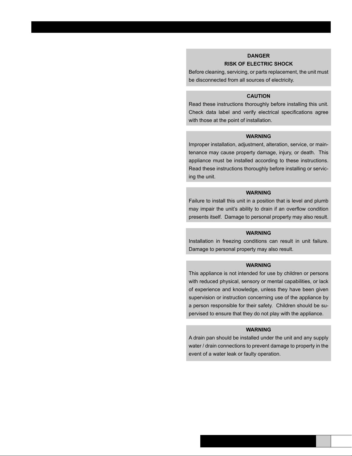
DANGER
RISK OF ELECTRIC SHOCK
Before cleaning, servicing, or parts replacement, the unit must
be disconnected from all sources of electricity.
CAUTION
Read these instructions thoroughly before installing this unit.
Check data label and verify electrical specications agree
with those at the point of installation.
WARNING
Improper installation, adjustment, alteration, service, or main-
tenance may cause property damage, injury, or death. This
appliance must be installed according to these instructions.
Read these instructions thoroughly before installing or servic-
ing the unit.
WARNING
Failure to install this unit in a position that is level and plumb
may impair the unit’s ability to drain if an overow condition
presents itself. Damage to personal property may also result.
WARNING
Installation in freezing conditions can result in unit failure.
Damage to personal property may also result.
WARNING
This appliance is not intended for use by children or persons
with reduced physical, sensory or mental capabilities, or lack
of experience and knowledge, unless they have been given
supervision or instruction concerning use of the appliance by
a person responsible for their safety. Children should be su-
pervised to ensure that they do not play with the appliance.
WARNING
A drain pan should be installed under the unit and any supply
water / drain connections to prevent damage to property in the
event of a water leak or faulty operation.
Comfort
BREEZE
TM
Model CB707
www.trioniaq.com
3
Page 4
Installation, Operation, & Maintenance Manual
3. Introduction
The benets of a properly humidied environment (35-55%
Relative Humidity) are many. They include both personal comfort as well as the preservation of furniture, draperies, carpets, wooden oors and cabinets, paintings, pianos, etc. Your
home can be more comfortable at a lower temperature (i.e.:
68° F) at 30-40% Relative Humidity (RH) than at 71° to 72° F
without controlled humidity. Since every degree of temperature setback represents about 3% of your heating costs, this
can represent a signicant annual savings. During the heating season, cold air inltrates the home and must be heated.
When heated, this air dries out and greatly increases its
capacity to hold more moisture. By using a humidier, a
source of water is provided to satisfy this increased moisture holding capacity, rather than having it drawn from occupants and the surrounding furnishings in the home.
3.1 Basic Operation
Your Comfort
ates on the principles of atomization and evaporation. A rotating
impeller pulls water from a small reservoir and slings it against
a periphery of impaction posts inside the unit. The force of the
impact causes the water to break into tiny droplets which are
subsequently discharged from the unit into the air. Once the
atomized water has exited the unit, it evaporates and raises the
relative humidity of the air.
If applicable, set the humidistat in the recommended range of
30-40% relative humidity for automatic humidity control during
the heating season. A lower setting may be necessary to prevent condensation on windows. If needed, an electronic humidistat is available to automatically reset the humidity setpoint as
the outside air temperature changes.
During the rst heating season, check the reservoir for mineral
build-up periodically to establish a cleaning schedule. Clean the
unit at the end of each heating season, or whenever mineral deposits appear to be impeding the performance of the humidier.
When shutting the humidier down for the summer months, start
by cleaning and mineral accumulation from the unit. Turn the
water off to the unit and dry any remaining water from the reservoir. See Page 8 for End Of Season Decommissioning.
BREEZE
TM
centrifugal atomizing humidier oper-
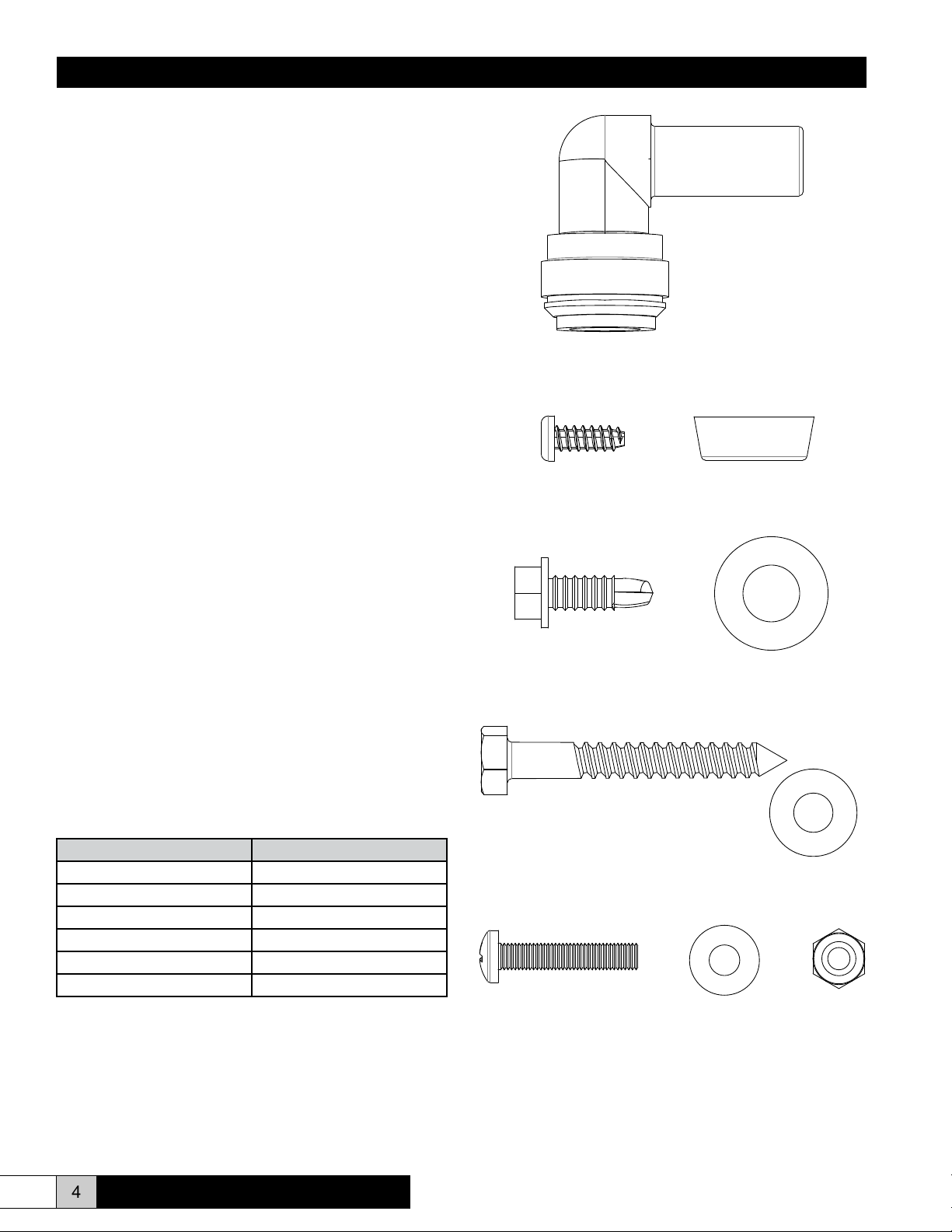
Hareware Details:
(1) Plug-in Elbow Tube Fitting 1/2” X 1/2”
P/N: 265570-001
Use: Attaches to the drain connection on the bottom of the unit
for shelf mounted applications.
(4) #10 X 1/2” Plastite Screw & Rubber Feet
P/N: 265378-226 & 266201-001
Use: Attaches to the bottom of the base
(6) #12 X 3/4” TEK Screw & #12 Flat Washer
P/N: 60645 & 120031-010
Use: Secures ange and mounting bracket to duct.
3.2 “What’s In The Box?”
Part Number Description
265562-001 or 265562-002 CB707 Humidier
265160-001 Humidistat
265310-001 Wall/Duct Mount Bracket
266152-002 Nozzle Extension Tube
265631-001 IOM Manual
266004-001 Parts Bag
4 www.trioniaq.com
(2) 1/4” X 2” Lag Screw & 1/4” Flat Washer
P/N: EST-175 & 120031-011
Use: Attaches mounting bracket to wall stud.
(2) #10-32 X 1” Pan Head Screw, #10 Flat washer, & #10-32
Nyloc Nut
P/N: 137790-310, 120031-009, & 123149-008
Use: Attaches unit to the mounting bracket.
Comfort
BREEZE
TM
Model CB707
Page 5

Installation, Operation, & Maintenance Manual
3.3 Unit Specications
Type of Unit Centrifugal Atomizing
Mounting Return Duct/Wall/Table-top/Ceiling
Capacity (GPD) 6 GPD, 2 Lbs./Hr., 0.9 Kg/Hr.
Water Supply 20-80 PSI (138-552 KPa)
Voltage(Amps) 120VAC(0.8A), 220VAC(0.4A)
Unit Dimensions 11”"W x 9.5" D x 12" H
279mm W x 241mm D x 305mm H
Water Connection 1/4” (6.35 mm) OD Tubing
Overow Connection 1/2” (12.7 mm) ID Tubing
Ducted Connection 3” Diameter (76 mm)
Shipping Weight 12.75 Lbs. (28 Kg)
Operating Weight 9 Lbs. (19.8 Kg)
Approvals ETL (US & Canada) CE (220V)
4. Installation
Prior to installing this product:
• Read the instructions carefully and completely to ensure
safe operation. Failure to follow the instructions could lead
to damage to the product or cause a hazardous condition.
• Check the ratings given on the product to make sure it is
suitable for your application.
When mounting the humidier on the face of a horizontal return
duct or on the face of a vertical return duct, certain conditions
must be met to ensure proper unit operation.
• Ensure that the duct surface is reinforced, if necessary, to
allow the unit to remain level and plumb.
• Locate the humidier at least four (4) linear feet upstream of
either the furnace fan and/or lter and any turn in the duct.
This will ensure that moisture does not accumulate in the
duct that may cause leakage, corrosion, or mold growth.
• Mount the humidier at least six (6) linear feet (preferably
10 feet) upstream of any electronic air cleaner. Failure to
follow this recommendation may result in excessive arcing
or power supply failure in the air cleaner.
• If the duct seams inside the duct are not at, locate the humidier at least three (3) linear feet upstream of the seam.
• If the humidication needs of the space require more than
one humidier, each unit should be installed a minimum of
three (3) linear feet apart.
• DO NOT use this humidier on the discharge or warm air
supply side of a forced air heating system. This will reduce
the efciency of the humidier and may cause additional
operational problems.
• DO NOT mount the humidier in a furnace jacket.
• DO NOT install the humidier where freezing conditions
could occur.
• DO NOT install on gravity hot air systems.
4.2.1 Wall Mounting The Humidier
Remember to select a location that is readily accessible for periodic inspection, cleaning, and service. The following table indicates the minimum allowable installation clearances.
4.1 Clearances
Left 2”
Right 2”
Top 5”
Bottom 0” (for surface mounting)
Back 2”
CAUTION
Trion recommends that this humidier be installed by a
trained HVAC professional. Do not connect the unit to the
power source until the installation is complete. A thorough
checkout of the unit installation should be completed before
operating the unit. Failure to follow these directions may void
the manufacturer’s original warranty.
4.2 Selecting A Location
The ComfortBREEZE CB-707 Humidier may be mounted di-
rectly to the return duct of your HVAC system with the discharge
entering the ductwork, it may be wall-mounted for atmospheric
dispersion, it may be hung from a ceiling (mounting hardware
not included for this type of installation), or it may be simply
mounted to a shelf. An indicating LED is located on the oposite
side of the base from the plumbing and electrical connections.
Ensure that this LED is visible, if desired, when selecting a
mounting location.
Figure 1
1. Referring to gure 1, using the mounting template, mark
the mounting holes on the wall. Ensure that the mounting
screws will penetrate wall-studs.
2. While holding the template against the wall, check with a
Comfort
BREEZE
TM
Model CB707
www.trioniaq.com
5
Page 6

Installation, Operation, & Maintenance Manual
level to ensure that the unit will be installed level and plumb.
If the unit is not level and plumb, ideal operation may not
be obtained.
3. Drill the mounting holes as shown on the template for
mounting the bracket to the wall.
4. Attached the mounting bracket to the wall using the lag
screws provided.
5. Place the base of the unit on the mounting bracket and se-
cure using the screws provided. See Figure #1 for details.
6. Once the humidier is mounted, place the dome on top of
the unit. It will snap into place. Ensure that the direction of
discharge is facing away from the wall.
7. Refer to the plumbing and electrical connection sections to
complete the installation.
4.2.2 Duct Mounting The Humidier
gasket is placed between the duct and the ange.
7. Place the base of the unit on the mounting bracket and se-
cure using the screws provided. See Figure #2 for details.
8. Insert Nozzle Extension Tube through gasket hole in duct
approximately 2”.
9. With the humidier mounted, place the dome on top of the
unit. It will snap into place. Ensure that the direction of
discharge is correct for your application; either wall or duct
mount.
10. Insert Nozzle Extension Tube from duct into humidier
dome, discharge nozzle. Tube will insert approximately 1”
inside dome discharge nozzle against stops.
4.2.3 Ceiling Mounting The Humidier
Figure 2
IMPORTANT
The unit must be installed so that interconnection can be
made to the source of electrical supply without the use of an
extension cord.
1. Referring to gure 2, using the mounting template, mark the
mounting holes on the duct. Ensure that the discharge tube
is lined up with the centerline of the duct.
2. While holding the template against the duct, check with a
level to ensure that the unit will be installed level and plumb.
If the unit is not level and plumb, ideal operation may not
be obtained.
3. If you are installing the humidier on a return duct, also
mark the discharge hole as indicated on the template.
4. Drill the mounting holes as shown on the template for
mounting the bracket to the duct.
5. Cut out the discharge hole while taking care not to injure
yourself. Once the hole is cut out, ensure that the edges
will not damage the humidier.
6. Attached the mounting bracket and discharge ange to the
wall or duct using the screws provided. Ensure that the
Figure 3
1. Refer to Figure 3. The humidier base has holes at the four
corners that may be used to suspend the unit from the ceil-
ing using threaded rods.
2. Using #10-32 threaded rods, suspend the unit at least 24
inches from the ceiling to prevent mist from impinging on
the ceiling.
3. Ensure that the discharge mist is not entrained within air
currents that may cause the mist to accumulate on the
threaded rods or back onto the unit itself. Dripping may
occur.
4. Once the humidier is mounted, place the dome on top of
the unit. It will snap into place. Ensure that the direction of
discharge is correct for your application.
5. Refer to the plumbing and electrical sections for completing
the installation.
6 www.trioniaq.com
Comfort
BREEZE
TM
Model CB707
Page 7
Installation, Operation, & Maintenance Manual
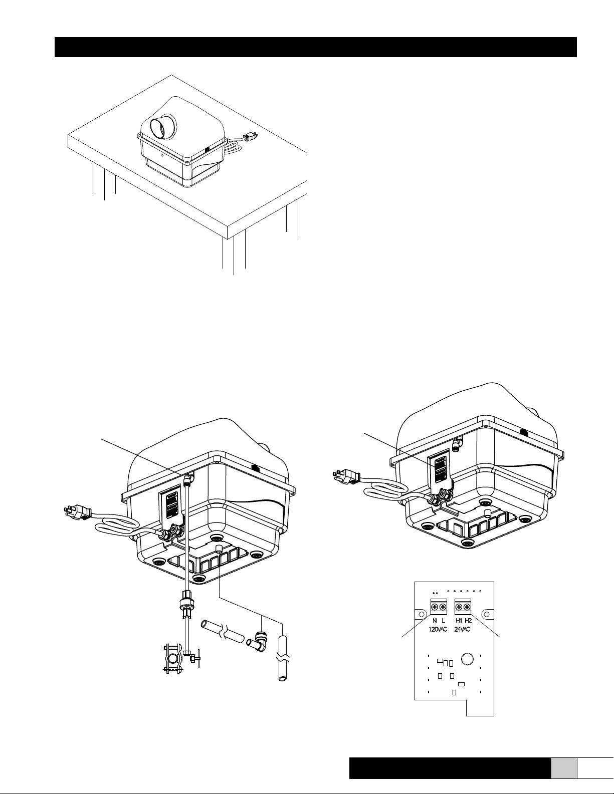
4.2.4 Shelf Mounting The Humidier
Figure 4
1. The unit may be placed on a shelf for direct space humidi-
cation without the use of additional hardware. Rubber
mounting feet supplied with the humidier may be attached
to the base of the humidier.
2. Ensure that the shelf is level and plumb before the unit is
placed into operation.
3. See Figure #4 for details.
4. Refer to the plumbing and electrical sections for completing
the installation.
details).
2. After the saddle valve and strainer are installed but before
inserting the line into the humidier supply tting, turn the
saddle valve to the open position and discharge the water
into a bucket or pan. This will allow the water to ush any
debris that may have accumulated in the line during the in-
stallation process. Once this is complete, close the saddle
valve.
3. Attach the line to the humidier by simply pushing the line
into the push-to-lock tting and pulling back slightly to seat
the line. If it becomes necessary to remove the line, press
on the release ring around where the line goes into the t-
ting to release the line and pull it out.
4. Connect the drain hose to the overow tting and run this
to an open, gravity drain. The end of this line must not be
submerged in water or be trapped.
5. Turn on the saddle valve.
6. Upon starting the humidier, you will notice water owing
into the humidier. If any water discharges from the overow drain hose, ensure that the unit is level and plumb. If
water continues to ow from the overow, please refer to
the troubleshooting chart.
4.4 Electrical (for all installation types)
Removal of electrical cover plate will reveal the connection terminals for the humidistat (all models) and the high voltage termi-
nals (220 VAC models only). See Figures 6 & 6A below.
4.3 Plumbing (for all installation types)
Water Supply
Line Cord
Overflow Drain
Strainer/Filter
Saddle Valve
Figure 5
Electrical Cover
Plate
Line Cord
Figure 6
Power
Terminals
Humidistat
Terminals
1. Install a saddle valve and minimum 50 Mesh strainer (not
provided) on the nearest cold water supply pipe. (See the
instructions that accompany the saddle valve for additional
Comfort
BREEZE
TM
Model CB707
Figure 6A
www.trioniaq.com
7
Page 8

Installation, Operation, & Maintenance Manual
(220 VAC, UK VERSION)
MOTOR SOLENOID
VALV E
FLOAT
SWITCH
LED
GREEN-CATHODE
RED-CATHODE
BLK
BLU
RED
WHT
GRN
M
BLK
WHT
YEL
YEL
BLK
BLK
M1 M2 V1 V2 F1 F2
N L
H1 H2
BLK
WHT
HUMIDISTAT
5V
220 VAC
50HZ
BLK
WHT
GRN
2 1
YEL
• US models are factory equipped with a 120 VAC line cord
attached to the unit. This must be connected to an electrical outlet that is protected for short-circuit and overload
according to national, state and local codes/standards. It is
the installers responsibility to ensure compliance with these
codes. It is not necessary to operate this unit from a dedicated circuit. See Figure 7.
• UK (CE) models must be wired for 220 VAC from a protected circuit wired in accordance with any applicable codes or
standards. It is the responsibility of the installer to ensure
compliance with these codes. Disconnection means shall
be provided for xed wiring. See Figure 8.
Wiring Diagrams
MOTOR SOLENOID
VALV E
FLOAT
SWITCH
LED
M
BLK
RED
BLU
YEL
GRN
WHT
WHT
BLK
YEL
M1 M2 V1 V2 F1 F2
N L
GRN
WHT
120 VAC
60HZ
BLK
YEL
BLK
BLK
H1 H2
HUMIDISTAT
5V
BLK
2 1
GREEN-CATHODE
RED-CATHODE
WHT
5. Operation
With the CB707 properly mounted it must be determined if the
humidier will be run continuously through the use of jumper
between the H1 & H2 terminals on the control board or receive a
“call for humidity” from the humidistat provided. Humidistat wir-
ing is shown in the preceding wiring diagrams.
5.1 Preliminary Checkout and Start-up Sequence
1. Check that unit overow plumbing is properly connected.
2. Ensure that the supply plumbing is installed properly.
3. Open cold water supply and insure water is reaching the
unit. Incoming water line must be ltered.
4. Plug unit line cord into appropriate power source or con-
nect power to the unit supply terminals.
5. With the power on and the humidier set to run continu-
ously or if the humidistat has a “call for humidity”, the
indicator LED will illuminate Green and the unit will discharge a ne mist. If this is the initial startup the unit will
take approximately 60 seconds before producing the ne
mist. Mist will be discharged immediately on subsequent
running conditions. If the unit has been idle for a prolonged period of time such as the off season - summer
months, restart will again take approximately 60 seconds
to produce mist.
6. If at any point the indicator LED illuminates Red a fault
has been detected; service may be required and the fault
must be reset. Refer to the Maintenance & Troubleshoot-
ing section.
7. Refer to the humidistat manual for “call for humidity” set-
point information.
5.2 Starting/Stopping the unit
Figure 7
(120 VAC, US VERSION)
MOTOR SOLENOID
M
BLU
RED
WHT
BLK
BLK
GRN
M1 M2 V1 V2 F1 F2
N L
GRN
WHT
220 VAC
(220 VAC, UK VERSION)
VALV E
YEL
WHT
50HZ
Figure 8
YEL
BLK
YEL
FLOAT
SWITCH
BLK
BLK
H1 H2
HUMIDISTAT
5V
LED
BLK
2 1
GREEN-CATHODE
RED-CATHODE
WHT
In order to start the unit it is necessary to close the H1 & H2
terminals on the circuit board. This may be accomplished by
installing the included humidistat or by installing a jumper wire
between the “H” terminals on the control board. In order to stop
the unit you must only lower the humidistat setting to a point at
which the contacts are open. If the unit is set up for continu-
ous operation by installing a jumper between the “H” terminals
on the control board, you must remove the jumper wire placed
between terminals H1 & H2 on the control board.
5.3 End of Season Decommissioning
1. At the end of the humidication season it is recommended that the unit be run dry of all remaining water in the
reservoir. Please do the following...
2. Close the water supply valve so that water can not ow
to the unit.
3. Adjust the humidistat all the way up so that the unit be-
gins to operate. If the unit is dispersing into a duct, en-
sure that the blower is operating before allowing the unit
to operate.
4. The unit will produce mist, but will not be able to replenish
the reservoir because the water supply valve is closed.
5. Once the unit stops producing mist, adjust the humidistat
down and the unit should stop operating.
8 www.trioniaq.com
Comfort
BREEZE
TM
Model CB707
Page 9

Installation, Operation, & Maintenance Manual
6. Maintenance & Troubleshooting
DANGER - RISK OF ELECTRIC SHOCK
Before cleaning, servicing, or parts replacement, the unit must
be disconnected from all sources of electricity.
6.1 Cleaning Instructions
It will become necessary to clean your humidier as time goes
on. A red LED Service indicator light may light up. (Refer to
#3 in Control Board Faults Section, 1500 hour service interval.)
This will tell you that it is time to service your humidier. Please
follow the following procedure.
1. Perform the End-Of-Season Decommisioning procedure
described in section 5.3. This will cause the unit to run
out of water so that service can be performed without a
large amount of water inside the unit.
2. Adjust Humidistat to the lowest setting to ensure that
there is no call for humidity.
3. Unplug the humidier in order to remove power before
servicing the unit.
4. Close the water supply valve so that no water may ow to
the humidier and remove the supply line from the pushto-lock tting. See section 4.3 Step 3 for details regarding removing the tube from the tting.
5. Remove the top discharge dome and wipe out any accumulated mineral build-up.
6. Examine the atomizing posts and gently clean any mineral build-up from the posts using a soft cloth. Ensure
great care is taken not to damage, bend, or break the
atomizing posts.
7. Remove the cover from the electrical box and unwire the
line cord and humidistat wires from the terminals. It is not
necessary to remove the strain releif ttings.
8. On either side of the circuit board there are mounting
screws. Remove the screw that secures the ground wire
(left). Loosen the screw on the right. It is not necessary
to remove it completely. (See Figure 9)
9. With the dome removed from the unit, remove the four
screws that secure the motor base to the reservoir base.
(See Figure 10)
10. The mid-section of the humidifer may now be lifted from
the base. This will allow access to the water reservoir,
impeller pump, solenoid valve, oat switch, control enclosure and air lter media. The circuit board will slide out
with the mid-section of the unit.
11. Examine the oat switch and ensure that it moves freely
upon the shaft. If there is any binding, gently clean the
shaft to allow the oat to move freely.
12. Wipe away any additional mineral build-up that may have
accumulated elsewhere within the humidier.
13. Examine lter media and remove and clean as necessary
using a mild soap and water solution. Allow to dry and
reinstall between vent holes and pinch pins.
14. Reassemble the humidier in the reverse of disassembly. Assembly may be simplied by turning the humidier
upside-down. This will simplify the alignment of the circuit board with the grooves on either side of the electrical
compartment.
15. Reset the service timer (RED LED) by cycling the hu-
midistat on & off three times within 10 seconds. Return
to service.
Figure 9
Figure 10
Comfort
BREEZE
TM
Model CB707
www.trioniaq.com
9
Page 10

Installation, Operation, & Maintenance Manual
6.2 Control Board Faults & Reset
Faults are indicated by a ashing LED located on the base of the
unit opposite the electrical access cover. (See gure11)
1. Red LED, blinking repeatedly .25 second ON & .25 sec-
ond OFF. Unit will not function.
A. Float switch not opening after 10 minutes of ll.
a) Damaged or stuck oat switch. This would
cause overow to drain.
b) Restricted input water ow; clogged solenoid
valve or ow restrictor.
c) Leaking reservoir.
d) Bad control board.
2. Red LED, blinking repeatedly 1 second On & 1 second
OFF. Unit will not function.
B. Float switch not closing in 30 minutes.
a) Damaged or stuck oat switch. This would
cause reduced mist or dry air discharge.
b) Clogged pump or damaged pump/impeller.
c) Bad control board.
3. Red LED, solid ON. Unit will continue to function.
A) 1,500 service interval on “call for humidity” hours
Control Board Fault Reset
All control board faults are reset by cycling the “call for humidity” signal ON and OFF, 3 times in ten seconds. This may be
accomplished by rotating the humidistat knob from the minimum
setting to the maximum setting repetitively.
Figure 11
10 www.trioniaq.com
Comfort
BREEZE
TM
Model CB707
Page 11
Installation, Operation, & Maintenance Manual
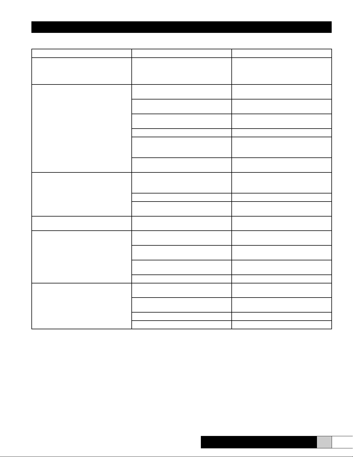
6.3 Troubleshooting Chart
Problem/Symtom Probable Cause Corrective Action
Power is applied and the LED does not
illuminate.
Humidistat contacts are closed but the
unit will not produce mist
Motor will not operate/turn Motor internal thermal protective device
LED is glowing solid RED Service Timer has expired Follow the Cleaning instructions and
Unit will not operate and LED is blinking
rapidly. (1/4 second interval)
Unit will not operate & LED is blinking
slowly (1 second interval)
No issue. The LED does not illuminate unless the
H1 & H2 terminals are closed on the
circuit board or the humidistat contacts
are closed.
No water pressure or water supply valve
is closed.
Solenoid Valve is not operating Ensure that there is power supplied to
Motor is not operating Ensure that there is power supplied to
Circuit Board has failed/fuse is blown Replace circuit board.
Duct Static pressure is too high Ensure unit is connected to the return
Impeller pump broken or missing Ensure pump has not fallen out of the
is open.
Motor has failed Replace motor.
Impeller is stuck Remove obstruction or replace motor as
Damaged or stuck oat switch Clean oat switch and ensure proper
Restricted input water ow; clogged
solenoid valve
Leaking reservoir Inspect the unit for cracks in the reser-
Control Board has failed. Replace control board.
Damaged or stuck oat switch Clean oat switch and ensure proper
Clogged pump or damaged pump/impreller
Bad control board Replace control board.
Solenoid Valve stuck open Replace solenoid valve.
Ensure that the supply water is on.
the valve. Check control board output.
the motor. Check control board output.
duct and not the supply duct. Relocate if
necessary.
impeller tube.
Remove power and allow motor to cool.
Restart unit and ensure proper operation.
If motor will not turn, replace motor.
necessary.
reset the service interval. See page 8.
operation. Replace switch is necessary.
Inspect orice located in solenoid valve
discharge tube.
voir. Replace reservoir if necessary.
operation. Replace switch is necessary.
Ensure pump has not fallen out of the
impeller tube.
Comfort
BREEZE
TM
Model CB707
www.trioniaq.com
11
Page 12

Installation, Operation, & Maintenance Manual
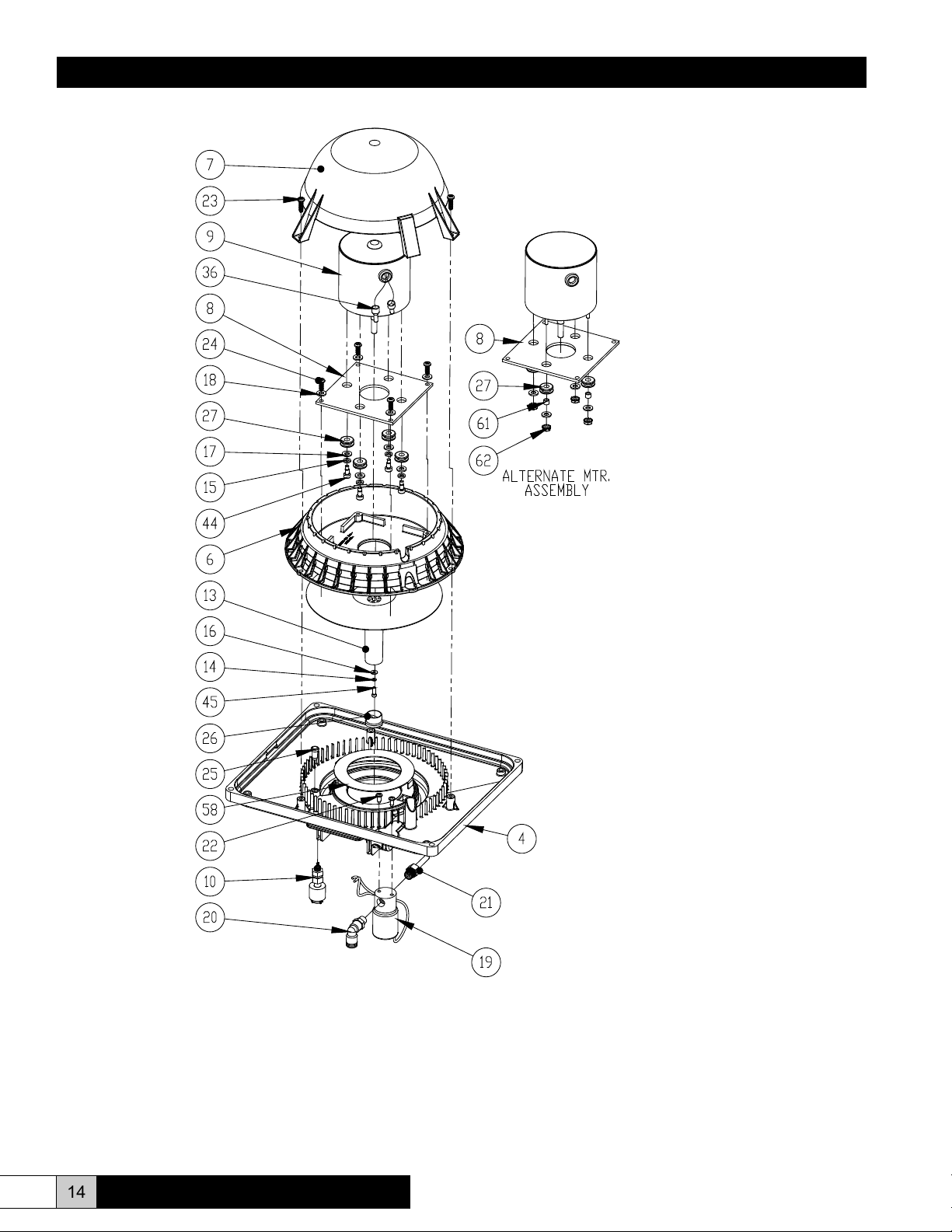
QUANTITY
1 1 265311-001 UNIT BASE
1 2 265433-001 ENCLOSURE ENTRY BRACKET
1 3 265317-001 COVER PLATE
1 4 265307-001 DIFFUSER/DRAIN BASE (MUST BE ORDERED WITH ITEM 58)
4 5 265559-001 STRAIN RELIEF CONNECTOR W/SEALING NUT
1 6 265308-001 MOTOR BASE
1 7 265309-001 MOTOR COVER
1 8 265443-001 MOTOR MOUNTING PLATE
1 9 265376-001 SHADED POLE MOTOR
1 10 265377-001 FLT015 FLOAT SWITCH
1 11 265304-001 HOOD (NOT SHOWN)
1 12 265303-001 HOOD EXTENSION (NOT SHOWN)
1 13 265479-001 IMPELLER
1 14 120609-003 LOCKWASHER, SPRING, SST #4
4 15 120609-007 LOCKWASHER, SS #10
1 16 120608-005 WASHER, FLAT, SST #4
4 17 120608-009 FLATWASHER, #10 SST
4 18 120608-008 FLATWASHER, #8 SST
1 19 G-109 G-109 SOLENOID VALVE ASSEMBLY
1 20 165001-001 "PUSH-TO-LOCK" MALE ELBOW 1/4" X 1/8 NPT
1 21 265305-001 FILL FITTING, 1/8" NPT
2 22 166129-001 SCREW, #8 X 3/8" PH PH THRD CUT., SST
7 23 265378-220 SCREW, PHIL PH, PLASTITE . #8 x 5/8" LG.
4 24 265378-219 SCREW, PHIL PH, PLASTITE . #8 x 1/2" LG.
1 25 265560-001 RUBBER SEAL PLUG
1 26 8A PUMP
4 27 4009 GROMMET
1 28 265574-001 5MM LENS (707)
1 29 265577-001 SPC125 SPACER (707)
1 30 265575-001 5MM ROUND LITEPIPE
1 31 265573-001 LED LAMP, RED/GREEN
1 32 265576-001 CNX K CABLE ASSEMBLY (707)
1 35 265612-001 WHITE NWPE FILTER 18.5" (707)
2 36 127258-001 PIGTAIL CONNECTOR
1 37 265627-001 ENCLOSURE GASKET
1 38 265627-002 DOOR GASKET
1 39 265628-001 POWER CORD 6'
1 40 265440-001 CONTROL BOARD (707), 120VAC (SEE NOTE 1 ON PAGE 13)
- 40 265440-002 CONTROL BOARD (707) 220VAC (SEE NOTE 1 ON PAGE 13)
4 41 121078-004 WASHER, SEALING-BARTITE #8
1 42 265582-001 INSULATION BOARD (707)
4 43 265785-001 O-RING
4 44 266199-001 SHOULDER SCREW, #8-32 X 1/4"
1 45 158931-004 CAP SCREW, SOCKET HEAD #4-40 X 3/8
ITEM
NO.
PART NUMBER DESCRIPTION
12 www.trioniaq.com
Comfort
BREEZE
TM
Model CB707
Page 13

Installation, Operation, & Maintenance Manual
1 46 166260-001 RETAINING RING
2 47 137790-001 SCREW - PH PAN HD, MACH., #6-32 X 1/4"
2 48 120032-002 EXT TOOTH LOCKWASHER, #6
1 49 142854-206S SCREW, PHIL FH MACH S/S, #8-32 x 1/2
1 50 121800-004 NUT-LOCKWASHER, #8-32
1 51 121800-003 NUT-LOCKWASHER, #6-32
1 52 146548-047 SCREW, PAN HD MACH PHIL S/S, #8-32 X 1/2"
1 53 266152-002 NOZZLE EXTENSION TUBE (NOT SHOWN)
2 54 266793-001 FEMALE THREADED STANDOFF
1 55 266455-001 CONTROL BOARD BRACKET, RH
1 56 266455-002 CONTROL BOARD BRACKET, LH
2 57 266792-001 LOCKNUT, PG9
1 58 266826-001 INLET RING
1 59 265442-001 GROUND PLATE ASS'Y
2 60 265627-003 ENCLOSURE GASKET
4 61 265038-004 SPACER, ALUM. - 0.25 OD x 0.166 ID x 0.19 LG
4 62 137245-004 NUT-LOCKWASHER - SST, #8-32
1 67 265310-001 WALL MOUNTING BRACKET (707) (NOT SHOWN)
1 68 265160-001 HUMIDISTAT (NOT SHOWN)
Note 1: 220 VAC units use control board (item 40) part number 265440-002 only.
Note 2: If replacing item 4 (Diffuser/Drain Base), also order item 58 (Inlet Ring). Item 58 must be afxed to Item 4 using clear
silicone multi-purpose RTV.
Comfort
BREEZE
TM
Model CB707
www.trioniaq.com
13
Page 14
Installation, Operation, & Maintenance Manual
14 www.trioniaq.com
*See Note 2 on page 13.
Comfort
BREEZE
TM
Model CB707
Page 15

Installation, Operation, & Maintenance Manual
Comfort
BREEZE
TM
Model CB707
www.trioniaq.com
15
Page 16

Installation, Operation, & Maintenance Manual
16 www.trioniaq.com
Comfort
BREEZE
TM
Model CB707
Page 17

Installation, Operation, & Maintenance Manual
Comfort
BREEZE
TM
Model CB707
www.trioniaq.com
17
Page 18

®
Trion
101 McNeill Rd. | Sanford, NC 27330
P: 800.884.0002 | F: 800.458.2379 | www.trioniaq.com | customerservice@trioniaq.com
Form No. 265631-001 rev. 01/15/2013 © Trion 2013. All Rights Reserved.
 Loading...